WO2016104014A1 - Dispositif de mesure de bruit - Google Patents
Dispositif de mesure de bruit Download PDFInfo
- Publication number
- WO2016104014A1 WO2016104014A1 PCT/JP2015/082892 JP2015082892W WO2016104014A1 WO 2016104014 A1 WO2016104014 A1 WO 2016104014A1 JP 2015082892 W JP2015082892 W JP 2015082892W WO 2016104014 A1 WO2016104014 A1 WO 2016104014A1
- Authority
- WO
- WIPO (PCT)
- Prior art keywords
- power supply
- noise
- electric field
- voltage
- line
- Prior art date
Links
Images


Classifications
-
- G—PHYSICS
- G01—MEASURING; TESTING
- G01R—MEASURING ELECTRIC VARIABLES; MEASURING MAGNETIC VARIABLES
- G01R19/00—Arrangements for measuring currents or voltages or for indicating presence or sign thereof
-
- G—PHYSICS
- G01—MEASURING; TESTING
- G01R—MEASURING ELECTRIC VARIABLES; MEASURING MAGNETIC VARIABLES
- G01R29/00—Arrangements for measuring or indicating electric quantities not covered by groups G01R19/00 - G01R27/00
- G01R29/08—Measuring electromagnetic field characteristics
Definitions
- the present invention relates to a noise measuring device that measures noise generated in a power supply line or a signal line.
- CISPR International Radio Interference Special Committee 15 as an international standard for electromagnetic interference (EMI) noise.
- CISPR15 the emission requirements for evaluating the noise conducted from the lighting device to the AC power supply port (AC power supply line) are required for the noise terminal voltage measured in the frequency band of 30 MHz or less, and in the frequency band of 30 MHz or more. There are some which are required for the conducted interference wave measured by, and the frequency band varies depending on the emission.
- FIG. 1 is a block configuration diagram showing a measurement system of a conducted interference wave defined by CISPR15.
- a CDN (Coupling and Decoupling Network for Emission) 4 is inserted between an AC power source 2 and an EUT (EUT) 3 connected by a pair of power lines 1a and 1b.
- EUT EUT
- an LED lighting device is taken as an example of the EUT 3.
- the CDN 4 fixes and stabilizes the impedance of the power supply lines 1a and 1b, and outputs a common mode voltage generated between the power supply lines 1a and 1b and the ground. This voltage is input to the spectrum analyzer 6 via a 6 dB attenuator (ATT) 5 and measured.
- ATT 6 dB attenuator
- Patent Document 1 discloses a signal detection device that mode-separates the noise terminal voltage measured in a frequency band of 30 MHz or less into a differential mode voltage and a common mode voltage.
- a power suppression line that suppresses a high-frequency signal (noise) included in a power supply voltage and a signal separation filter that prevents transmission of a high-frequency signal are provided in series on a power supply line connected to a power supply input terminal. It has been.
- the power supply line is further provided with a common mode signal detection circuit and a normal mode (differential mode) signal detection circuit independently of each other.
- the common mode signal (noise) and the normal mode signal generated from the device under test and entering from the power supply output terminal are individually detected by the common mode signal detection circuit and the normal mode signal detection circuit. Therefore, it becomes easy to analyze the cause of the high-frequency signal generated in the device under measurement, and an appropriate noise countermeasure can be taken.
- Patent Document 2 discloses a measuring device that can detect normal mode noise and common mode noise independently at the same location on the line.
- This measuring apparatus includes first and second electric field probes, and takes in the combined voltage separation circuit the voltages detected for the pair of lines by each electric field probe.
- the combined voltage separation circuit is composed of three resistors having the same resistance value and a balun transformer, and outputs a common-phase combined voltage of voltages input from the first and second input terminals from one of the first or second output terminals, The reverse phase composite voltage is output from the other.
- a reverse-phase composite voltage of approximately zero volts is output to the first output terminal
- a common-phase composite voltage of a predetermined magnitude is output to the second output terminal.
- a common-phase combined voltage having a predetermined magnitude is output to the first output terminal, and a reverse-phase combined voltage of approximately zero volts is output to the second output terminal. Therefore, by measuring the state of the voltage output from the first and second output terminals with a spectrum analyzer, it is possible to determine whether the noise on the pair of lines is normal mode noise or common mode noise.
- the conducted interference wave measurement system shown in FIG. 1 defined by the conventional CISPR 15 evaluates only the common mode voltage between two wires. Considering the actual usage environment of LED lighting equipment, not only noise due to the common mode but also noise due to the differential mode is generated, which may lead to a market accident such as noise entering the AM radio. Therefore, when considering noise countermeasures for LED lighting equipment and the like, it is necessary to take countermeasures not only for common mode noise defined in CISPR15 but also for differential mode noise. It can not be done.
- the noise terminal voltage is mode-separated into the differential mode voltage and the common mode voltage, it is possible to take measures against the differential mode noise.
- the mode separation of the noise terminal voltage performed by the signal detection device is performed in a frequency band of 30 MHz or less, and when applied to a conducted interference wave measured in a frequency band of 30 MHz or more, a large number of signal detection devices are configured. Resonance occurs due to the influence of the inductor L and the capacitor C, and mode separation is difficult.
- a noise measurement device configured to include an impedance stabilization device that stabilizes the impedance of a pair of power supply lines or signal lines, and measures noise generated in the power supply lines or signal lines
- a first electric field detection unit is connected to one power supply line or signal line to detect an electric field generated in one power supply line or signal line, and a first electric field detection is performed on a first electromagnetic shield unit connected to a reference potential.
- a first electric field detector having a high input impedance and covered with a portion;
- a second electric field detector is connected to the other power supply line or signal line to detect an electric field generated in the other power supply line or signal line, and a second electric field detector is connected to the second electromagnetic shield connected to the reference potential.
- a second electric field detector having a high input impedance, the portion of which is covered; The first voltage between one power supply line or signal line detected by the first electric field detector and the reference potential, and the other power supply line or signal line detected by the second electric field detector and the reference potential And the input first and second voltages to the common mode voltage with respect to the reference potential of each power supply line or signal line and the differential mode voltage between each power supply line or signal line. And a mode separator for separation.
- the first electric field detector of the first electric field detector is connected to one of the pair of power supply lines or signal lines
- the second electric field detector of the second electric field detector is connected to the other
- the mode separation is performed without using a large number of inductors L and capacitors C as in the conventional signal detection device disclosed in Patent Document 1, the mode separation is performed in a frequency band of 30 MHz or more without being influenced by resonance. It becomes possible to do. Further, unlike the conventional measuring device disclosed in Patent Document 2, the voltage between the reference voltage of each one line of the power supply line or the signal line is measured as the first and second voltages, and these voltages are supplied to the power supply line.
- the voltage is converted into a voltage between two lines of the line or signal line (common mode voltage) and a voltage between the two lines (differential mode voltage) by a mode separator. Therefore, it is possible not only to determine whether the noise is the normal mode or the common mode, but also to measure the noise of each mode. Therefore, it is possible to confirm the correlation between the noise voltage of each mode generated in the power supply line or the signal line and the generation tendency of the noise radiated into the space. It is possible to specify whether the noise of the mode is the main factor. For this reason, it is possible to take an effective countermeasure against spatial radiation noise according to the noise mode.
- the present invention is characterized in that the impedance stabilizing device is provided between a power supply source connected by a pair of power lines and the device under measurement.
- a ring core is attached to a portion not covered with the first electromagnetic shield portion of the first electric field detector and a portion not covered with the second electromagnetic shield portion of the second electric field detector. It is characterized by being.
- the external noise flying to the portion not covered by the first and second electromagnetic shield portions of the first and second electric field detectors is blocked from being superimposed on the measurement system by the ring core. Therefore, only noise conducted to the power supply line or the signal line can be measured. Therefore, it is possible to accurately measure normal mode noise and common mode noise generated in the power supply line or signal line.
- noise generated in the power supply line or signal line can be separated into a normal mode and a common mode in a frequency band of 30 MHz or higher.
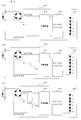
- FIG. 1 is a schematic block diagram of a noise measuring device according to an embodiment of the present invention. It is a circuit diagram which shows the internal structure of CDN which comprises the noise measuring device by one embodiment. It is a longitudinal cross-sectional view of the electric field probe which comprises the noise measuring device by one embodiment.
- A) is a circuit diagram which shows the structure of LED illumination in the noise measuring device by one Embodiment
- B) is a circuit diagram which shows the structure of LED illumination provided with the capacitor for countermeasures for differential mode voltage
- (c) These are the circuit diagrams which show the structure of LED illumination provided with the common mode choke coil for a countermeasure of a common mode voltage.
- a graph showing the results of measuring the noise for the LED lighting before and after the countermeasure for noise of the differential mode voltage is measured, (a) is a graph showing the results of measuring the differential mode voltage generated in a pair of power supply lines that supply power to the LED lighting, (B) is a graph which shows the result of having measured the common mode voltage which arises in a pair of power supply line.
- a graph showing the result of measuring the noise for the LED lighting before and after the noise countermeasure for the common mode voltage is taken is taken, (a) is a graph showing the result of measuring the differential mode voltage generated in the pair of power supply lines for supplying power to the LED lighting, (B) is a graph which shows the result of having measured the common mode voltage which arises in a pair of power supply line.
- (A) shows the horizontal polarization of the noise radiated into the space by the common mode voltage generated in the pair of power supply lines.
- the graph which shows the measurement result (b) is a graph which shows the result of having measured the vertical polarization of the noise radiated
- FIG. 2 is a schematic block diagram of the noise measuring apparatus 11 according to an embodiment of the present invention.
- a CDN 4 is inserted between the AC power supply 2 and the EUT connected by a pair of power supply lines 1a and 1b, similarly to the measurement system defined by the conventional CISPR 15 shown in FIG.
- the object to be measured of the noise measuring device 11 is a noise voltage generated in the pair of power supply lines 1a and 1b.
- This noise voltage is connected to the spectrum analyzer 6 via the 6 dB ATT 5 as in the conventional measurement system shown in FIG. Is input and measured.
- an LED illumination device is taken as an example as the EUT 3.
- the CDN4 has an internal configuration shown in the circuit diagram of FIG. 3, and includes inductors L1 and L2, capacitors C1 and C2, and resistors R1, R2, and R3 in accordance with CISPR15.
- the CDN 4 receives power supply from the AC power supply 2 on the AE (auxiliary device) port 4a side.
- the AE port 4a has three terminals of L phase, N phase, and PE (GND), the PE terminal is grounded, and the power supply lines 1a and 1b are connected to the L phase and the N phase.
- the EUT 3 is connected to the EUT port 4b, and the measuring port 4c is terminated with a 50 ⁇ resistor. From the measurement port 4c, a common mode voltage between the L-phase and N-phase two wires and the ground is output, but in the present embodiment, the measurement port 4c is terminated and output from the measurement port 4c as described above. Voltage is not used.
- the CDN 4 constitutes an impedance stabilization device that stabilizes the impedance of the pair of power supply lines 1a and 1b. As described above, the CDN 4 is inserted between the AC power supply 2 and the EUT 3 so that the power supply lines 1a and 1b Fix and stabilize the impedance. In this embodiment, the CDN 4 having a corresponding frequency of 30 MHz to 300 MHz, a common mode impedance of 150 ⁇ , a differential mode impedance of 100 ⁇ , and an isolation of each mode of 30 dB or more is used.
- the noise measuring device 11 further includes first and second electric field probes 12 and 13, a hybrid balun 14, and an amplifier 15.
- the first and second electric field probes 12 and 13 are shown in a longitudinal sectional view in FIG. 4, and a core wire 22 is provided in a semi-ridged cable 21 made of a coaxial cable, and a tip 22a of the core wire 22 is exposed to the outside. I am doing.
- a core wire 22 is provided in a semi-ridged cable 21 made of a coaxial cable, and a tip 22a of the core wire 22 is exposed to the outside. I am doing.
- the other end of the core wire 22 is connected to the hybrid balun 14 via a high impedance element (not shown).
- the hybrid balun 14 is connected via a resistance element having a high resistance value of 1 M ⁇ . Therefore, a large current is prevented from flowing into the hybrid balun 14 from the first and second electric field probes 12 and 13.
- the semi-ridged cable 21 is housed in a hollow portion of a shield case 23 that constitutes an outer shield, and the end 22 a of the core wire 22 is exposed from the end of the shield case 23.
- the shield case 23 is formed by bending a copper plate into a rectangular cylinder and is connected to a ground potential that is a reference potential.
- the core wire 22 of the first electric field probe 12 constitutes a first electric field detector whose tip 22a is connected to one power supply line 1a.
- the shield case 23 of the first electric field probe 12 constitutes a first electromagnetic shield part connected to a reference potential that covers the first electric field detection part.
- the first electric field probe 12 is a first electric field detector having a high input impedance, in which a first electric field detector is connected to one power line 1a and detects an electric field generated in one power line 1a.
- the core wire 22 of the second electric field probe 13 constitutes a second electric field detection unit whose tip 22a is connected to the other power supply line 1b.
- the shield case 23 of the second electric field probe 13 constitutes a second electromagnetic shield part that covers the second electric field detection part and is connected to a reference potential.
- the second electric field probe 13 is a second electric field detector having a high input impedance, in which the second electric field detector is connected to the other power line 1b and detects the electric field generated in the other power line 1b.
- first electric field detector and the second electric field detector are not limited to the electric field probes 12 and 13 having a high input impedance, and may be any detection device that increases the input impedance.
- a ferrite ring core as shown in FIG. 2 is formed on the portion of the first electric field probe 12 that is not covered by the shield case 23 and the portion of the second electric field probe 13 that is not covered by the shield case 23. 31 is mounted. Further, the ferrite ring core 31 is also attached to the measurement line between the hybrid balun 14 and the amplifier 15 and the measurement line between the amplifier 15 and the ATT 5.
- the hybrid balun 14 is a balun (balanced / unbalanced converter) having a plurality of ports, and includes two input ports 14a and 14b for ch1 and ch2 and two output ports 14c and 14d.
- Hybrid baluns include transmission line transformer winding type and microstrip line type.
- the hybrid balun 14 in the present embodiment is a transmission line transformer winding type hybrid balun.
- the hybrid balun 14 has a first electric field between one power line 1a detected by the first electric field probe 12 and the ground potential at the ch1 input port 14a, and a second electric field at the ch2 input port 14b. A second voltage between the other power supply line 1b detected by the probe 13 and the ground potential is input.
- the hybrid balun 14 includes a mode separator that separates the input first and second voltages into a common mode voltage with respect to the ground potential of the power supply lines 1a and 1b and a differential mode voltage between the power supply lines 1a and 1b. Constitute. The separated common mode voltage is output to the output port 14c, and the differential mode voltage is output to the output port 14d.
- a 50 ⁇ termination resistor When measuring the common mode voltage, a 50 ⁇ termination resistor is connected to the output port 14d as shown in FIG. 2, and when measuring the differential mode voltage, a 50 ⁇ termination resistor is connected to the output port 14c.
- the amplifier 15, ATT5, and spectrum analyzer 6 are connected to the output port 14d. Since each of these output voltages in each mode is very small, the output of the hybrid balun 14 is amplified by the amplifier 15 and measured.
- the mode separator is not limited to the hybrid balun 14 having four input / output ports in the present embodiment. It may be a hybrid having one output port and having three or more input / output ports, including one having three input / output ports that output by switching the common mode voltage and the differential mode voltage. What is necessary is just to provide the synthesizer or distributor which can convert a line-to-ground voltage into a 2-line-to-ground voltage or a 2-line voltage.
- LED lighting equipment as EUT3 includes, for example, LED lighting 3A having the circuit configuration shown in FIG.
- the LED illumination 3A rectifies the AC voltage input from the AC power source 2 via the CDN 4 by the bridge diode 41 and smoothes it by the smoothing circuit 42.
- the smoothed DC voltage is converted by the DC-DC converter 43 to drive the LEDs 44 connected in series. At this time, switching noise generated in the DC-DC converter 43 may be conducted to the pair of power supply lines 1a and 1b.
- FIG. 5 (b) shows a circuit configuration of the LED illumination 3B provided with a capacitor 45 for countermeasure against a differential mode voltage among noise voltages on the power supply lines 1a and 1b.
- a capacitor 45 for countermeasure against a differential mode voltage among noise voltages on the power supply lines 1a and 1b.
- inserting a capacitor between DC lines affects only the differential mode voltage.
- by providing a capacitor 45 between the DC lines immediately after the bridge diode 41 that is, between DC plus and DC minus, only the noise of the differential mode voltage is reduced and the noise of the common mode voltage is changed. It was confirmed by experiment that it does not.
- FIG. 6 shows the result of this experiment
- FIG. 6A is a graph showing the peak detection result obtained by measuring the differential mode voltage, which is the voltage between the power supply lines 1a and 1b, from the output port 14d of the hybrid balun 14. is there.
- the horizontal axis represents the frequency [MHz]
- the vertical axis represents the differential mode voltage (dB ⁇ V).
- the light-color characteristic line 51 is measured with respect to the LED illumination 3A of FIG. 5A that does not have noise countermeasures without the capacitor 45.
- the dark characteristic line 52 has noise countermeasures that have the capacitor 45.
- the result measured about LED illumination 3B of FIG.5 (b) is represented.
- FIG. 5B is a graph showing a peak detection result obtained by measuring a common mode voltage, which is a two-to-ground voltage of the power supply lines 1 a and 1 b, from the output port 14 c of the hybrid balun 14.
- a common mode voltage which is a two-to-ground voltage of the power supply lines 1 a and 1 b
- the horizontal axis represents frequency [MHz]
- the vertical axis represents common mode voltage (dB ⁇ V).
- the characteristic line 53 of light ink color is measured for the LED illumination 3A of FIG. 5A that does not have noise countermeasures without the capacitor 45.
- the dark characteristic line 54 has noise countermeasures having the capacitor 45.
- the result measured about LED illumination 3B of FIG.5 (b) is represented.
- FIG. 5 (c) shows a circuit configuration of the LED illumination 3C provided with a common mode choke coil 46 for countermeasures against a common mode voltage among noise voltages on the power supply lines 1a and 1b.
- a common mode choke coil is inserted between DC lines, only the common mode voltage is affected.
- a common mode choke coil 46 is provided between the DC lines immediately after the bridge diode 41 to reduce only the noise of the common mode voltage and the noise of the differential mode voltage does not change. It was done.
- FIG. 7 shows the result of this experiment
- FIG. 7A is a graph showing the peak detection result obtained by measuring the differential mode voltage, which is the voltage between the power supply lines 1a and 1b, from the output port 14d of the hybrid balun 14. is there.
- the horizontal axis represents the frequency [MHz]
- the vertical axis represents the differential mode voltage (dB ⁇ V).
- the dark characteristic line 61 indicates that the common mode choke coil 46 does not have the common mode choke coil 46. The result measured about the LED illumination 3C of FIG.
- FIG. 5B is a graph showing a peak detection result obtained by measuring a common mode voltage, which is a two-to-ground voltage of the power supply lines 1a and 1b, from the output port 14c of the hybrid balun 14.
- a common mode voltage which is a two-to-ground voltage of the power supply lines 1a and 1b
- the horizontal axis represents frequency [MHz]
- the vertical axis represents common mode voltage (dB ⁇ V).
- the dark characteristic line 64 indicates that the common mode choke coil 46 does not have the common mode choke coil 46. The result measured about the LED illumination 3C of FIG.
- noise countermeasures for the differential mode voltage including the capacitor 45 and the noise countermeasures for the common mode voltage including the common mode choke coil 46 are examples, and are general. Each noise countermeasure is limited to these methods. It is not something.
- the core wire 22 of the first electric field probe 12 is connected to one of the pair of power supply lines 1a and 1b, and the core wire 22 of the second electric field probe 13 is connected to the other.
- the first voltage between one power supply line 1a detected by the first electric field probe 12 and the ground potential, and between the other power supply line 1b detected by the second electric field probe 13 and the ground potential. Is input to the hybrid balun 14 to determine the common mode voltage with respect to the ground potential of the power supply lines 1a and 1b and the differential mode voltage between the power supply lines 1a and 1b.
- the noise measuring apparatus 11 it is possible to take measures not only for the common mode noise defined in CISPR15 but also for the differential mode noise. Further, since the mode separation is performed without using a large number of inductors L and capacitors C as in the conventional signal detection device disclosed in Patent Document 1, the mode separation is performed in a frequency band of 30 MHz or more without being influenced by resonance. It becomes possible to do. Further, unlike the conventional measuring device disclosed in Patent Document 2, the ground-to-ground voltage of each of the power lines 1a and 1b is measured as the first and second voltages, and these voltages are measured as the power line 1a.
- 1b are converted by the hybrid balun 14 into the voltage between the two wires (common mode voltage) and the voltage between the two wires (differential mode voltage).
- the actually measured voltage is different between the two-wire-to-ground and the one-wire-to-ground, but in this embodiment, the power supply lines 1a and 1b Since the voltage between the ground is measured, the one-line-to-ground voltage mode-separated by the hybrid balun 14 has the same result as the two-line-to-ground voltage or the two-line voltage measured.
- the noise measuring apparatus 11 can measure the noise itself of each mode. Therefore, according to the noise measuring apparatus 11 according to the present embodiment, it is possible to confirm the correlation between the noise voltage of each mode generated in the power supply lines 1a and 1b and the tendency of the noise radiated to the space. It is possible to specify which mode of noise generated in the power supply lines 1a and 1b is the main cause of the occurrence of. For this reason, it is possible to take an effective countermeasure against spatial radiation noise according to the noise mode.
- FIG. 8 is a graph showing a result of measuring noise radiated into the space by the common mode voltage generated in the power supply lines 1a and 1b at a point 10 m away from the power supply lines 1a and 1b.
- the graph of FIG. 6A shows the result of measuring the horizontal polarization of this spatial radiation noise, where the horizontal axis represents frequency [MHz] and the vertical axis represents noise level (Noise Level) [dB ⁇ V / m]. .
- the dark characteristic line 72 indicates that the common mode choke coil 46 does not have the common mode choke coil 46.
- the graph of the same figure (b) shows the result of having measured the vertical polarization of said spatial radiation noise
- the horizontal axis of the said graph is frequency [MHz]
- shaft is noise level (Noise Level) [dB ⁇ V / m. ].
- the light-color characteristic line 73 is measured with respect to the LED illumination 3A in FIG. 5A that does not include the common-mode choke coil 46
- the dark-color characteristic line 74 indicates the common-mode choke coil 46. The result measured about the LED illumination 3C of FIG.
- the common mode choke coil 46 As described above, by providing the common mode choke coil 46 between the DC lines, noise of the common mode voltage generated in the power supply lines 1a and 1b from the characteristic lines 63 and 64 in the graph shown in FIG. 7B is reduced. Although it has been confirmed that the common mode choke coil 46 is provided between the DC lines from the characteristic lines 71 to 74 in the graphs shown in FIGS. 8A and 8B, the power lines 1a and 1b Regarding the horizontal and vertical polarization of spatial radiation noise generated at a point 10m ahead, it was confirmed that the noise level was reduced below the allowable noise value specified by CISPR15 in all frequency bands of 30MHz to 300MHz.
- the noise measuring apparatus 11 includes a hybrid balun 14 provided between the AC power supply 2 and the EUT 3 connected by a pair of power supply lines 1a and 1b, and receives power supply from the AC power supply 2.
- a hybrid balun 14 provided between the AC power supply 2 and the EUT 3 connected by a pair of power supply lines 1a and 1b, and receives power supply from the AC power supply 2.
- Both normal mode noise and common mode noise generated in the pair of power supply lines 1a and 1b by the DC-DC converter 43 of the operating LED illumination 3A can be measured. Therefore, it is possible to specify which mode of noise is the main cause of noise generated in the pair of power supply lines 1a and 1b by the LED lighting 3A and radiated from the power supply lines 1a and 1b to the space in a frequency band of 30 MHz or higher. It becomes possible to do.
- the external noise flying to the portion of the first and second electric field probes 12 and 13 that is not covered by the shield case 23 is measured by the ferrite ring core 31. It is possible to measure only noise conducted to the power supply lines 1a and 1b. Therefore, it is possible to accurately measure normal mode noise and common mode noise generated in the power supply lines 1a and 1b.
- the noise measuring device 11 has been described for measuring noise conducted to the pair of power supply lines 1a and 1b, but is not limited to the pair of power supply lines 1a and 1b.
- the noise generated in the signal line can also be measured in the same manner as in the above embodiment, and the same effect as in the above embodiment can be obtained.
- the LED illumination 3A that operates with an AC power source is exemplified as the EUT 3.
- the EUT 3 is not only a device that operates with an AC power supply, but also a device that inputs a DC voltage, converts it to an arbitrary DC voltage with a DC-DC converter, and applies it to a load, that is, a device that operates with a DC power supply. But you can. Even in this case, it is possible to measure noise in the same manner as in the above embodiment, and the same effects as in the above embodiment can be achieved.
Abstract
L'invention vise à fournir un dispositif de mesure de bruit capable de spécifier quel mode de bruit généré dans une ligne de puissance est la principale cause de bruit émis et de mettre en œuvre des mesures efficaces contre le bruit émis à travers l'air, dans un dispositif de mesure du bruit 11 selon la présente invention, le noyau 22 d'une première sonde de champ électrique 12 est connecté à l'un d'une paire de lignes d'alimentation électrique 1a, 1b et le noyau 22 d'une seconde sonde de champ électrique 13 est connecté à l'autre, et une première tension détectée par la première sonde de champ électrique 12 entre la première ligne d'alimentation électrique 1a et un potentiel de terre et une seconde tension détectée par la seconde sonde de champ électrique 13 entre l'autre ligne d'alimentation électrique 1b et le potentiel de terre sont appliquées à un balun hybride 14. En conséquence, la tension de mode commun des lignes d'alimentation électrique 1a, 1b par rapport au potentiel de terre et la tension de mode différentiel entre les lignes d'alimentation électrique 1a, 1b sont identifiées.
Applications Claiming Priority (2)
| Application Number | Priority Date | Filing Date | Title |
|---|---|---|---|
| JP2014266716 | 2014-12-26 | ||
| JP2014-266716 | 2014-12-26 |
Publications (1)
| Publication Number | Publication Date |
|---|---|
| WO2016104014A1 true WO2016104014A1 (fr) | 2016-06-30 |
Family
ID=56150047
Family Applications (1)
| Application Number | Title | Priority Date | Filing Date |
|---|---|---|---|
| PCT/JP2015/082892 WO2016104014A1 (fr) | 2014-12-26 | 2015-11-24 | Dispositif de mesure de bruit |
Country Status (1)
| Country | Link |
|---|---|
| WO (1) | WO2016104014A1 (fr) |
Citations (4)
| Publication number | Priority date | Publication date | Assignee | Title |
|---|---|---|---|---|
| JP2004257770A (ja) * | 2003-02-24 | 2004-09-16 | Sony Corp | 高周波電位検出装置 |
| JP2005214902A (ja) * | 2004-01-30 | 2005-08-11 | Tdk Corp | 信号検出装置 |
| JP2012013456A (ja) * | 2010-06-29 | 2012-01-19 | Fujitsu Ltd | 電磁界プローブ |
| WO2014038027A1 (fr) * | 2012-09-06 | 2014-03-13 | 株式会社日立製作所 | Sonde de courant, système de mesure de courant, et procédé de mesure de courant |
-
2015
- 2015-11-24 WO PCT/JP2015/082892 patent/WO2016104014A1/fr active Application Filing
Patent Citations (4)
| Publication number | Priority date | Publication date | Assignee | Title |
|---|---|---|---|---|
| JP2004257770A (ja) * | 2003-02-24 | 2004-09-16 | Sony Corp | 高周波電位検出装置 |
| JP2005214902A (ja) * | 2004-01-30 | 2005-08-11 | Tdk Corp | 信号検出装置 |
| JP2012013456A (ja) * | 2010-06-29 | 2012-01-19 | Fujitsu Ltd | 電磁界プローブ |
| WO2014038027A1 (fr) * | 2012-09-06 | 2014-03-13 | 株式会社日立製作所 | Sonde de courant, système de mesure de courant, et procédé de mesure de courant |
Similar Documents
| Publication | Publication Date | Title |
|---|---|---|
| US8125291B2 (en) | Electromagnetic interference noise separator | |
| JP4840050B2 (ja) | 部分放電測定装置 | |
| US8937480B2 (en) | High frequency detection device and coaxial cable including the same | |
| US10502778B2 (en) | Method and apparatus for electric arc detection | |
| CN203406161U (zh) | 带闭合磁路空心线圈与电阻分压器组合的电子式互感器 | |
| US10067165B2 (en) | Isolated differential voltage probe for EMI noise source | |
| CN107003340B (zh) | 电流传感器以及测定装置 | |
| US10488444B2 (en) | Device for measuring a magnetic field | |
| JP2017051085A (ja) | アクティブノイズ抑制装置 | |
| US9110105B2 (en) | High performance sensor for partial discharge signal-analyzing systems | |
| WO2016104014A1 (fr) | Dispositif de mesure de bruit | |
| CN211321216U (zh) | 共差模分离装置及干扰隔离器 | |
| CN108519508B (zh) | 一种测量交流与直流电流的比较仪 | |
| CN108226602B (zh) | 用于测量交流电的时间导数的方法和传感器 | |
| Van den Bossche et al. | EMC combined di/dt current probe | |
| US11714115B2 (en) | Instrument interfacing method and device thereof | |
| Zhao et al. | Electromagnetic Compatibility | |
| CN215871185U (zh) | 一种开关电源端口传导噪声自动检测对消电路 | |
| JP2018042306A (ja) | フィルタ回路及びワイヤレス電力伝送システム | |
| KR101692584B1 (ko) | 조명 장치 | |
| Sallier et al. | Low-cost measurement system and filter for reduction of EMC interferences in radio-frequency applications | |
| Zhao et al. | Conducted EMI Noise Generation Mechanism, Measurement and Diagnosis | |
| JP7023138B2 (ja) | 絶縁監視システム | |
| Ishigami et al. | Development of measuring apparatus for conducted disturbance voltage using TEM cell up to 1 GHz | |
| Gallo et al. | Experimental evaluation of conducted emissions by variable-speed drives under variable operating conditions |
Legal Events
| Date | Code | Title | Description |
|---|---|---|---|
| 121 | Ep: the epo has been informed by wipo that ep was designated in this application |
Ref document number: 15872583 Country of ref document: EP Kind code of ref document: A1 |
|
| NENP | Non-entry into the national phase |
Ref country code: DE |
|
| NENP | Non-entry into the national phase |
Ref country code: JP |
|
| 122 | Ep: pct application non-entry in european phase |
Ref document number: 15872583 Country of ref document: EP Kind code of ref document: A1 |