WO2016104014A1 - Noise measurement device - Google Patents
Noise measurement device Download PDFInfo
- Publication number
- WO2016104014A1 WO2016104014A1 PCT/JP2015/082892 JP2015082892W WO2016104014A1 WO 2016104014 A1 WO2016104014 A1 WO 2016104014A1 JP 2015082892 W JP2015082892 W JP 2015082892W WO 2016104014 A1 WO2016104014 A1 WO 2016104014A1
- Authority
- WO
- WIPO (PCT)
- Prior art keywords
- power supply
- noise
- electric field
- voltage
- line
- Prior art date
Links
Images


Classifications
-
- G—PHYSICS
- G01—MEASURING; TESTING
- G01R—MEASURING ELECTRIC VARIABLES; MEASURING MAGNETIC VARIABLES
- G01R19/00—Arrangements for measuring currents or voltages or for indicating presence or sign thereof
-
- G—PHYSICS
- G01—MEASURING; TESTING
- G01R—MEASURING ELECTRIC VARIABLES; MEASURING MAGNETIC VARIABLES
- G01R29/00—Arrangements for measuring or indicating electric quantities not covered by groups G01R19/00 - G01R27/00
- G01R29/08—Measuring electromagnetic field characteristics
Definitions
- the present invention relates to a noise measuring device that measures noise generated in a power supply line or a signal line.
- CISPR International Radio Interference Special Committee 15 as an international standard for electromagnetic interference (EMI) noise.
- CISPR15 the emission requirements for evaluating the noise conducted from the lighting device to the AC power supply port (AC power supply line) are required for the noise terminal voltage measured in the frequency band of 30 MHz or less, and in the frequency band of 30 MHz or more. There are some which are required for the conducted interference wave measured by, and the frequency band varies depending on the emission.
- FIG. 1 is a block configuration diagram showing a measurement system of a conducted interference wave defined by CISPR15.
- a CDN (Coupling and Decoupling Network for Emission) 4 is inserted between an AC power source 2 and an EUT (EUT) 3 connected by a pair of power lines 1a and 1b.
- EUT EUT
- an LED lighting device is taken as an example of the EUT 3.
- the CDN 4 fixes and stabilizes the impedance of the power supply lines 1a and 1b, and outputs a common mode voltage generated between the power supply lines 1a and 1b and the ground. This voltage is input to the spectrum analyzer 6 via a 6 dB attenuator (ATT) 5 and measured.
- ATT 6 dB attenuator
- Patent Document 1 discloses a signal detection device that mode-separates the noise terminal voltage measured in a frequency band of 30 MHz or less into a differential mode voltage and a common mode voltage.
- a power suppression line that suppresses a high-frequency signal (noise) included in a power supply voltage and a signal separation filter that prevents transmission of a high-frequency signal are provided in series on a power supply line connected to a power supply input terminal. It has been.
- the power supply line is further provided with a common mode signal detection circuit and a normal mode (differential mode) signal detection circuit independently of each other.
- the common mode signal (noise) and the normal mode signal generated from the device under test and entering from the power supply output terminal are individually detected by the common mode signal detection circuit and the normal mode signal detection circuit. Therefore, it becomes easy to analyze the cause of the high-frequency signal generated in the device under measurement, and an appropriate noise countermeasure can be taken.
- Patent Document 2 discloses a measuring device that can detect normal mode noise and common mode noise independently at the same location on the line.
- This measuring apparatus includes first and second electric field probes, and takes in the combined voltage separation circuit the voltages detected for the pair of lines by each electric field probe.
- the combined voltage separation circuit is composed of three resistors having the same resistance value and a balun transformer, and outputs a common-phase combined voltage of voltages input from the first and second input terminals from one of the first or second output terminals, The reverse phase composite voltage is output from the other.
- a reverse-phase composite voltage of approximately zero volts is output to the first output terminal
- a common-phase composite voltage of a predetermined magnitude is output to the second output terminal.
- a common-phase combined voltage having a predetermined magnitude is output to the first output terminal, and a reverse-phase combined voltage of approximately zero volts is output to the second output terminal. Therefore, by measuring the state of the voltage output from the first and second output terminals with a spectrum analyzer, it is possible to determine whether the noise on the pair of lines is normal mode noise or common mode noise.
- the conducted interference wave measurement system shown in FIG. 1 defined by the conventional CISPR 15 evaluates only the common mode voltage between two wires. Considering the actual usage environment of LED lighting equipment, not only noise due to the common mode but also noise due to the differential mode is generated, which may lead to a market accident such as noise entering the AM radio. Therefore, when considering noise countermeasures for LED lighting equipment and the like, it is necessary to take countermeasures not only for common mode noise defined in CISPR15 but also for differential mode noise. It can not be done.
- the noise terminal voltage is mode-separated into the differential mode voltage and the common mode voltage, it is possible to take measures against the differential mode noise.
- the mode separation of the noise terminal voltage performed by the signal detection device is performed in a frequency band of 30 MHz or less, and when applied to a conducted interference wave measured in a frequency band of 30 MHz or more, a large number of signal detection devices are configured. Resonance occurs due to the influence of the inductor L and the capacitor C, and mode separation is difficult.
- a noise measurement device configured to include an impedance stabilization device that stabilizes the impedance of a pair of power supply lines or signal lines, and measures noise generated in the power supply lines or signal lines
- a first electric field detection unit is connected to one power supply line or signal line to detect an electric field generated in one power supply line or signal line, and a first electric field detection is performed on a first electromagnetic shield unit connected to a reference potential.
- a first electric field detector having a high input impedance and covered with a portion;
- a second electric field detector is connected to the other power supply line or signal line to detect an electric field generated in the other power supply line or signal line, and a second electric field detector is connected to the second electromagnetic shield connected to the reference potential.
- a second electric field detector having a high input impedance, the portion of which is covered; The first voltage between one power supply line or signal line detected by the first electric field detector and the reference potential, and the other power supply line or signal line detected by the second electric field detector and the reference potential And the input first and second voltages to the common mode voltage with respect to the reference potential of each power supply line or signal line and the differential mode voltage between each power supply line or signal line. And a mode separator for separation.
- the first electric field detector of the first electric field detector is connected to one of the pair of power supply lines or signal lines
- the second electric field detector of the second electric field detector is connected to the other
- the mode separation is performed without using a large number of inductors L and capacitors C as in the conventional signal detection device disclosed in Patent Document 1, the mode separation is performed in a frequency band of 30 MHz or more without being influenced by resonance. It becomes possible to do. Further, unlike the conventional measuring device disclosed in Patent Document 2, the voltage between the reference voltage of each one line of the power supply line or the signal line is measured as the first and second voltages, and these voltages are supplied to the power supply line.
- the voltage is converted into a voltage between two lines of the line or signal line (common mode voltage) and a voltage between the two lines (differential mode voltage) by a mode separator. Therefore, it is possible not only to determine whether the noise is the normal mode or the common mode, but also to measure the noise of each mode. Therefore, it is possible to confirm the correlation between the noise voltage of each mode generated in the power supply line or the signal line and the generation tendency of the noise radiated into the space. It is possible to specify whether the noise of the mode is the main factor. For this reason, it is possible to take an effective countermeasure against spatial radiation noise according to the noise mode.
- the present invention is characterized in that the impedance stabilizing device is provided between a power supply source connected by a pair of power lines and the device under measurement.
- a ring core is attached to a portion not covered with the first electromagnetic shield portion of the first electric field detector and a portion not covered with the second electromagnetic shield portion of the second electric field detector. It is characterized by being.
- the external noise flying to the portion not covered by the first and second electromagnetic shield portions of the first and second electric field detectors is blocked from being superimposed on the measurement system by the ring core. Therefore, only noise conducted to the power supply line or the signal line can be measured. Therefore, it is possible to accurately measure normal mode noise and common mode noise generated in the power supply line or signal line.
- noise generated in the power supply line or signal line can be separated into a normal mode and a common mode in a frequency band of 30 MHz or higher.
- FIG. 1 is a schematic block diagram of a noise measuring device according to an embodiment of the present invention. It is a circuit diagram which shows the internal structure of CDN which comprises the noise measuring device by one embodiment. It is a longitudinal cross-sectional view of the electric field probe which comprises the noise measuring device by one embodiment.
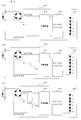
- A) is a circuit diagram which shows the structure of LED illumination in the noise measuring device by one Embodiment
- B) is a circuit diagram which shows the structure of LED illumination provided with the capacitor for countermeasures for differential mode voltage
- (c) These are the circuit diagrams which show the structure of LED illumination provided with the common mode choke coil for a countermeasure of a common mode voltage.
- a graph showing the results of measuring the noise for the LED lighting before and after the countermeasure for noise of the differential mode voltage is measured, (a) is a graph showing the results of measuring the differential mode voltage generated in a pair of power supply lines that supply power to the LED lighting, (B) is a graph which shows the result of having measured the common mode voltage which arises in a pair of power supply line.
- a graph showing the result of measuring the noise for the LED lighting before and after the noise countermeasure for the common mode voltage is taken is taken, (a) is a graph showing the result of measuring the differential mode voltage generated in the pair of power supply lines for supplying power to the LED lighting, (B) is a graph which shows the result of having measured the common mode voltage which arises in a pair of power supply line.
- (A) shows the horizontal polarization of the noise radiated into the space by the common mode voltage generated in the pair of power supply lines.
- the graph which shows the measurement result (b) is a graph which shows the result of having measured the vertical polarization of the noise radiated
- FIG. 2 is a schematic block diagram of the noise measuring apparatus 11 according to an embodiment of the present invention.
- a CDN 4 is inserted between the AC power supply 2 and the EUT connected by a pair of power supply lines 1a and 1b, similarly to the measurement system defined by the conventional CISPR 15 shown in FIG.
- the object to be measured of the noise measuring device 11 is a noise voltage generated in the pair of power supply lines 1a and 1b.
- This noise voltage is connected to the spectrum analyzer 6 via the 6 dB ATT 5 as in the conventional measurement system shown in FIG. Is input and measured.
- an LED illumination device is taken as an example as the EUT 3.
- the CDN4 has an internal configuration shown in the circuit diagram of FIG. 3, and includes inductors L1 and L2, capacitors C1 and C2, and resistors R1, R2, and R3 in accordance with CISPR15.
- the CDN 4 receives power supply from the AC power supply 2 on the AE (auxiliary device) port 4a side.
- the AE port 4a has three terminals of L phase, N phase, and PE (GND), the PE terminal is grounded, and the power supply lines 1a and 1b are connected to the L phase and the N phase.
- the EUT 3 is connected to the EUT port 4b, and the measuring port 4c is terminated with a 50 ⁇ resistor. From the measurement port 4c, a common mode voltage between the L-phase and N-phase two wires and the ground is output, but in the present embodiment, the measurement port 4c is terminated and output from the measurement port 4c as described above. Voltage is not used.
- the CDN 4 constitutes an impedance stabilization device that stabilizes the impedance of the pair of power supply lines 1a and 1b. As described above, the CDN 4 is inserted between the AC power supply 2 and the EUT 3 so that the power supply lines 1a and 1b Fix and stabilize the impedance. In this embodiment, the CDN 4 having a corresponding frequency of 30 MHz to 300 MHz, a common mode impedance of 150 ⁇ , a differential mode impedance of 100 ⁇ , and an isolation of each mode of 30 dB or more is used.
- the noise measuring device 11 further includes first and second electric field probes 12 and 13, a hybrid balun 14, and an amplifier 15.
- the first and second electric field probes 12 and 13 are shown in a longitudinal sectional view in FIG. 4, and a core wire 22 is provided in a semi-ridged cable 21 made of a coaxial cable, and a tip 22a of the core wire 22 is exposed to the outside. I am doing.
- a core wire 22 is provided in a semi-ridged cable 21 made of a coaxial cable, and a tip 22a of the core wire 22 is exposed to the outside. I am doing.
- the other end of the core wire 22 is connected to the hybrid balun 14 via a high impedance element (not shown).
- the hybrid balun 14 is connected via a resistance element having a high resistance value of 1 M ⁇ . Therefore, a large current is prevented from flowing into the hybrid balun 14 from the first and second electric field probes 12 and 13.
- the semi-ridged cable 21 is housed in a hollow portion of a shield case 23 that constitutes an outer shield, and the end 22 a of the core wire 22 is exposed from the end of the shield case 23.
- the shield case 23 is formed by bending a copper plate into a rectangular cylinder and is connected to a ground potential that is a reference potential.
- the core wire 22 of the first electric field probe 12 constitutes a first electric field detector whose tip 22a is connected to one power supply line 1a.
- the shield case 23 of the first electric field probe 12 constitutes a first electromagnetic shield part connected to a reference potential that covers the first electric field detection part.
- the first electric field probe 12 is a first electric field detector having a high input impedance, in which a first electric field detector is connected to one power line 1a and detects an electric field generated in one power line 1a.
- the core wire 22 of the second electric field probe 13 constitutes a second electric field detection unit whose tip 22a is connected to the other power supply line 1b.
- the shield case 23 of the second electric field probe 13 constitutes a second electromagnetic shield part that covers the second electric field detection part and is connected to a reference potential.
- the second electric field probe 13 is a second electric field detector having a high input impedance, in which the second electric field detector is connected to the other power line 1b and detects the electric field generated in the other power line 1b.
- first electric field detector and the second electric field detector are not limited to the electric field probes 12 and 13 having a high input impedance, and may be any detection device that increases the input impedance.
- a ferrite ring core as shown in FIG. 2 is formed on the portion of the first electric field probe 12 that is not covered by the shield case 23 and the portion of the second electric field probe 13 that is not covered by the shield case 23. 31 is mounted. Further, the ferrite ring core 31 is also attached to the measurement line between the hybrid balun 14 and the amplifier 15 and the measurement line between the amplifier 15 and the ATT 5.
- the hybrid balun 14 is a balun (balanced / unbalanced converter) having a plurality of ports, and includes two input ports 14a and 14b for ch1 and ch2 and two output ports 14c and 14d.
- Hybrid baluns include transmission line transformer winding type and microstrip line type.
- the hybrid balun 14 in the present embodiment is a transmission line transformer winding type hybrid balun.
- the hybrid balun 14 has a first electric field between one power line 1a detected by the first electric field probe 12 and the ground potential at the ch1 input port 14a, and a second electric field at the ch2 input port 14b. A second voltage between the other power supply line 1b detected by the probe 13 and the ground potential is input.
- the hybrid balun 14 includes a mode separator that separates the input first and second voltages into a common mode voltage with respect to the ground potential of the power supply lines 1a and 1b and a differential mode voltage between the power supply lines 1a and 1b. Constitute. The separated common mode voltage is output to the output port 14c, and the differential mode voltage is output to the output port 14d.
- a 50 ⁇ termination resistor When measuring the common mode voltage, a 50 ⁇ termination resistor is connected to the output port 14d as shown in FIG. 2, and when measuring the differential mode voltage, a 50 ⁇ termination resistor is connected to the output port 14c.
- the amplifier 15, ATT5, and spectrum analyzer 6 are connected to the output port 14d. Since each of these output voltages in each mode is very small, the output of the hybrid balun 14 is amplified by the amplifier 15 and measured.
- the mode separator is not limited to the hybrid balun 14 having four input / output ports in the present embodiment. It may be a hybrid having one output port and having three or more input / output ports, including one having three input / output ports that output by switching the common mode voltage and the differential mode voltage. What is necessary is just to provide the synthesizer or distributor which can convert a line-to-ground voltage into a 2-line-to-ground voltage or a 2-line voltage.
- LED lighting equipment as EUT3 includes, for example, LED lighting 3A having the circuit configuration shown in FIG.
- the LED illumination 3A rectifies the AC voltage input from the AC power source 2 via the CDN 4 by the bridge diode 41 and smoothes it by the smoothing circuit 42.
- the smoothed DC voltage is converted by the DC-DC converter 43 to drive the LEDs 44 connected in series. At this time, switching noise generated in the DC-DC converter 43 may be conducted to the pair of power supply lines 1a and 1b.
- FIG. 5 (b) shows a circuit configuration of the LED illumination 3B provided with a capacitor 45 for countermeasure against a differential mode voltage among noise voltages on the power supply lines 1a and 1b.
- a capacitor 45 for countermeasure against a differential mode voltage among noise voltages on the power supply lines 1a and 1b.
- inserting a capacitor between DC lines affects only the differential mode voltage.
- by providing a capacitor 45 between the DC lines immediately after the bridge diode 41 that is, between DC plus and DC minus, only the noise of the differential mode voltage is reduced and the noise of the common mode voltage is changed. It was confirmed by experiment that it does not.
- FIG. 6 shows the result of this experiment
- FIG. 6A is a graph showing the peak detection result obtained by measuring the differential mode voltage, which is the voltage between the power supply lines 1a and 1b, from the output port 14d of the hybrid balun 14. is there.
- the horizontal axis represents the frequency [MHz]
- the vertical axis represents the differential mode voltage (dB ⁇ V).
- the light-color characteristic line 51 is measured with respect to the LED illumination 3A of FIG. 5A that does not have noise countermeasures without the capacitor 45.
- the dark characteristic line 52 has noise countermeasures that have the capacitor 45.
- the result measured about LED illumination 3B of FIG.5 (b) is represented.
- FIG. 5B is a graph showing a peak detection result obtained by measuring a common mode voltage, which is a two-to-ground voltage of the power supply lines 1 a and 1 b, from the output port 14 c of the hybrid balun 14.
- a common mode voltage which is a two-to-ground voltage of the power supply lines 1 a and 1 b
- the horizontal axis represents frequency [MHz]
- the vertical axis represents common mode voltage (dB ⁇ V).
- the characteristic line 53 of light ink color is measured for the LED illumination 3A of FIG. 5A that does not have noise countermeasures without the capacitor 45.
- the dark characteristic line 54 has noise countermeasures having the capacitor 45.
- the result measured about LED illumination 3B of FIG.5 (b) is represented.
- FIG. 5 (c) shows a circuit configuration of the LED illumination 3C provided with a common mode choke coil 46 for countermeasures against a common mode voltage among noise voltages on the power supply lines 1a and 1b.
- a common mode choke coil is inserted between DC lines, only the common mode voltage is affected.
- a common mode choke coil 46 is provided between the DC lines immediately after the bridge diode 41 to reduce only the noise of the common mode voltage and the noise of the differential mode voltage does not change. It was done.
- FIG. 7 shows the result of this experiment
- FIG. 7A is a graph showing the peak detection result obtained by measuring the differential mode voltage, which is the voltage between the power supply lines 1a and 1b, from the output port 14d of the hybrid balun 14. is there.
- the horizontal axis represents the frequency [MHz]
- the vertical axis represents the differential mode voltage (dB ⁇ V).
- the dark characteristic line 61 indicates that the common mode choke coil 46 does not have the common mode choke coil 46. The result measured about the LED illumination 3C of FIG.
- FIG. 5B is a graph showing a peak detection result obtained by measuring a common mode voltage, which is a two-to-ground voltage of the power supply lines 1a and 1b, from the output port 14c of the hybrid balun 14.
- a common mode voltage which is a two-to-ground voltage of the power supply lines 1a and 1b
- the horizontal axis represents frequency [MHz]
- the vertical axis represents common mode voltage (dB ⁇ V).
- the dark characteristic line 64 indicates that the common mode choke coil 46 does not have the common mode choke coil 46. The result measured about the LED illumination 3C of FIG.
- noise countermeasures for the differential mode voltage including the capacitor 45 and the noise countermeasures for the common mode voltage including the common mode choke coil 46 are examples, and are general. Each noise countermeasure is limited to these methods. It is not something.
- the core wire 22 of the first electric field probe 12 is connected to one of the pair of power supply lines 1a and 1b, and the core wire 22 of the second electric field probe 13 is connected to the other.
- the first voltage between one power supply line 1a detected by the first electric field probe 12 and the ground potential, and between the other power supply line 1b detected by the second electric field probe 13 and the ground potential. Is input to the hybrid balun 14 to determine the common mode voltage with respect to the ground potential of the power supply lines 1a and 1b and the differential mode voltage between the power supply lines 1a and 1b.
- the noise measuring apparatus 11 it is possible to take measures not only for the common mode noise defined in CISPR15 but also for the differential mode noise. Further, since the mode separation is performed without using a large number of inductors L and capacitors C as in the conventional signal detection device disclosed in Patent Document 1, the mode separation is performed in a frequency band of 30 MHz or more without being influenced by resonance. It becomes possible to do. Further, unlike the conventional measuring device disclosed in Patent Document 2, the ground-to-ground voltage of each of the power lines 1a and 1b is measured as the first and second voltages, and these voltages are measured as the power line 1a.
- 1b are converted by the hybrid balun 14 into the voltage between the two wires (common mode voltage) and the voltage between the two wires (differential mode voltage).
- the actually measured voltage is different between the two-wire-to-ground and the one-wire-to-ground, but in this embodiment, the power supply lines 1a and 1b Since the voltage between the ground is measured, the one-line-to-ground voltage mode-separated by the hybrid balun 14 has the same result as the two-line-to-ground voltage or the two-line voltage measured.
- the noise measuring apparatus 11 can measure the noise itself of each mode. Therefore, according to the noise measuring apparatus 11 according to the present embodiment, it is possible to confirm the correlation between the noise voltage of each mode generated in the power supply lines 1a and 1b and the tendency of the noise radiated to the space. It is possible to specify which mode of noise generated in the power supply lines 1a and 1b is the main cause of the occurrence of. For this reason, it is possible to take an effective countermeasure against spatial radiation noise according to the noise mode.
- FIG. 8 is a graph showing a result of measuring noise radiated into the space by the common mode voltage generated in the power supply lines 1a and 1b at a point 10 m away from the power supply lines 1a and 1b.
- the graph of FIG. 6A shows the result of measuring the horizontal polarization of this spatial radiation noise, where the horizontal axis represents frequency [MHz] and the vertical axis represents noise level (Noise Level) [dB ⁇ V / m]. .
- the dark characteristic line 72 indicates that the common mode choke coil 46 does not have the common mode choke coil 46.
- the graph of the same figure (b) shows the result of having measured the vertical polarization of said spatial radiation noise
- the horizontal axis of the said graph is frequency [MHz]
- shaft is noise level (Noise Level) [dB ⁇ V / m. ].
- the light-color characteristic line 73 is measured with respect to the LED illumination 3A in FIG. 5A that does not include the common-mode choke coil 46
- the dark-color characteristic line 74 indicates the common-mode choke coil 46. The result measured about the LED illumination 3C of FIG.
- the common mode choke coil 46 As described above, by providing the common mode choke coil 46 between the DC lines, noise of the common mode voltage generated in the power supply lines 1a and 1b from the characteristic lines 63 and 64 in the graph shown in FIG. 7B is reduced. Although it has been confirmed that the common mode choke coil 46 is provided between the DC lines from the characteristic lines 71 to 74 in the graphs shown in FIGS. 8A and 8B, the power lines 1a and 1b Regarding the horizontal and vertical polarization of spatial radiation noise generated at a point 10m ahead, it was confirmed that the noise level was reduced below the allowable noise value specified by CISPR15 in all frequency bands of 30MHz to 300MHz.
- the noise measuring apparatus 11 includes a hybrid balun 14 provided between the AC power supply 2 and the EUT 3 connected by a pair of power supply lines 1a and 1b, and receives power supply from the AC power supply 2.
- a hybrid balun 14 provided between the AC power supply 2 and the EUT 3 connected by a pair of power supply lines 1a and 1b, and receives power supply from the AC power supply 2.
- Both normal mode noise and common mode noise generated in the pair of power supply lines 1a and 1b by the DC-DC converter 43 of the operating LED illumination 3A can be measured. Therefore, it is possible to specify which mode of noise is the main cause of noise generated in the pair of power supply lines 1a and 1b by the LED lighting 3A and radiated from the power supply lines 1a and 1b to the space in a frequency band of 30 MHz or higher. It becomes possible to do.
- the external noise flying to the portion of the first and second electric field probes 12 and 13 that is not covered by the shield case 23 is measured by the ferrite ring core 31. It is possible to measure only noise conducted to the power supply lines 1a and 1b. Therefore, it is possible to accurately measure normal mode noise and common mode noise generated in the power supply lines 1a and 1b.
- the noise measuring device 11 has been described for measuring noise conducted to the pair of power supply lines 1a and 1b, but is not limited to the pair of power supply lines 1a and 1b.
- the noise generated in the signal line can also be measured in the same manner as in the above embodiment, and the same effect as in the above embodiment can be obtained.
- the LED illumination 3A that operates with an AC power source is exemplified as the EUT 3.
- the EUT 3 is not only a device that operates with an AC power supply, but also a device that inputs a DC voltage, converts it to an arbitrary DC voltage with a DC-DC converter, and applies it to a load, that is, a device that operates with a DC power supply. But you can. Even in this case, it is possible to measure noise in the same manner as in the above embodiment, and the same effects as in the above embodiment can be achieved.
Abstract
To provide a noise measurement device capable of specifying which mode of noise generated in a power line is the primary cause of radiated noise and carrying out effective measures against noise radiated through the air, in a noise measurement device 11 according to the present invention, the core 22 of a first electric field probe 12 is connected to one of a pair of power supply lines 1a, 1b and the core 22 of a second electric field probe 13 is connected to the other, and a first voltage detected by the first electric field probe 12 between the one power supply line 1a and a ground potential and a second voltage detected by the second electric field probe 13 between the other power supply line 1b and the ground potential are applied to a hybrid balun 14. As a result, the common mode voltage of the power supply lines 1a, 1b in relation to the ground potential and the differential mode voltage between the power supply lines 1a, 1b are identified.
Description
本発明は、電源線または信号線に生じるノイズを測定するノイズ測定装置に関するものである。
The present invention relates to a noise measuring device that measures noise generated in a power supply line or a signal line.
従来、電磁妨害(EMI)雑音に関する国際規格として、CISPR(国際無線障害特別委員会)15がある。このCISPR15における、照明機器からAC電源ポート(AC電源線)に伝導するノイズを評価するエミッション要求には、30MHz以下の周波数帯で測定する雑音端子電圧に要求されるものと、30MHz以上の周波数帯で測定する伝導妨害波に要求されるものとがあり、エミッションによって周波数帯が異なる。
Conventionally, there is CISPR (International Radio Interference Special Committee) 15 as an international standard for electromagnetic interference (EMI) noise. In CISPR15, the emission requirements for evaluating the noise conducted from the lighting device to the AC power supply port (AC power supply line) are required for the noise terminal voltage measured in the frequency band of 30 MHz or less, and in the frequency band of 30 MHz or more. There are some which are required for the conducted interference wave measured by, and the frequency band varies depending on the emission.
図1は、CISPR15で規定されている伝導妨害波の測定系を示すブロック構成図である。CISPR15では、一対の電源線1a,1bで接続されたAC電源2とEUT(供試機器)3との間に、CDN(Coupling and Decoupling Network for Emission)4が挿入される。ここでは、EUT3としてLED照明機器が例にされている。CDN4は、電源線1a,1bのインピーダンスを固定させて安定化し、電源線1a,1bと大地との間に生じるコモンモード電圧を出力する。この電圧は、6dBのアッテネータ(ATT)5を介してスペクトラムアナライザ6に入力され、測定される。
FIG. 1 is a block configuration diagram showing a measurement system of a conducted interference wave defined by CISPR15. In the CISPR 15, a CDN (Coupling and Decoupling Network for Emission) 4 is inserted between an AC power source 2 and an EUT (EUT) 3 connected by a pair of power lines 1a and 1b. Here, an LED lighting device is taken as an example of the EUT 3. The CDN 4 fixes and stabilizes the impedance of the power supply lines 1a and 1b, and outputs a common mode voltage generated between the power supply lines 1a and 1b and the ground. This voltage is input to the spectrum analyzer 6 via a 6 dB attenuator (ATT) 5 and measured.
特許文献1には、30MHz以下の周波数帯で測定する上記の雑音端子電圧を、ディファレンシャルモード電圧とコモンモード電圧とにモード分離する信号検出装置が開示されている。この信号検出装置は、電源入力端子に接続された電源線に、電源電圧に含まれる高周波信号(ノイズ)を抑止する信号抑止フィルタと、高周波信号の伝達を阻止する信号分離フィルタとが直列に設けられている。電源線には、さらに、コモンモード信号検出回路とノーマルモード(ディファレンシャルモード)信号検出回路とが互いに独立に設けられている。被測定機器から発生して電源出力端子から侵入したコモンモード信号(ノイズ)とノーマルモード信号とは、これらコモンモード信号検出回路とノーマルモード信号検出回路とによって個別に検出される。したがって、被測定機器で発生した高周波信号の発生原因の解析が容易となり、的確なノイズ対策が可能になる。
Patent Document 1 discloses a signal detection device that mode-separates the noise terminal voltage measured in a frequency band of 30 MHz or less into a differential mode voltage and a common mode voltage. In this signal detection device, a power suppression line that suppresses a high-frequency signal (noise) included in a power supply voltage and a signal separation filter that prevents transmission of a high-frequency signal are provided in series on a power supply line connected to a power supply input terminal. It has been. The power supply line is further provided with a common mode signal detection circuit and a normal mode (differential mode) signal detection circuit independently of each other. The common mode signal (noise) and the normal mode signal generated from the device under test and entering from the power supply output terminal are individually detected by the common mode signal detection circuit and the normal mode signal detection circuit. Therefore, it becomes easy to analyze the cause of the high-frequency signal generated in the device under measurement, and an appropriate noise countermeasure can be taken.
また、特許文献2には、ノーマルモードノイズとコモンモードノイズとを線路の同一箇所で独立に検出可能な測定装置が開示されている。この測定装置は、第1および第2の電界プローブを備え、各電界プローブで一対の線路について検出される電圧を合成電圧分離回路に取り込む。合成電圧分離回路は、抵抗値の等しい3つの抵抗とバルントランスとから構成され、第1および第2入力端から入力した電圧の同相合成電圧を第1または第2出力端の一方から出力し、逆相合成電圧を他方から出力する。一対の線路上のノイズがノーマルモードの場合、第1出力端にはほぼゼロボルトの逆相合成電圧、第2出力端には所定大きさの同相合成電圧が出力される。また、一対の線路上のノイズがコモンモードの場合、第1出力端には所定大きさの同相合成電圧、第2出力端にはほぼゼロボルトの逆相合成電圧が出力される。したがって、第1および第2出力端から出力される電圧の状態をスペクトラムアナライザで測定することで、一対の線路上のノイズがノーマルモードノイズなのか、コモンモードノイズなのかを判別することができる。
Also, Patent Document 2 discloses a measuring device that can detect normal mode noise and common mode noise independently at the same location on the line. This measuring apparatus includes first and second electric field probes, and takes in the combined voltage separation circuit the voltages detected for the pair of lines by each electric field probe. The combined voltage separation circuit is composed of three resistors having the same resistance value and a balun transformer, and outputs a common-phase combined voltage of voltages input from the first and second input terminals from one of the first or second output terminals, The reverse phase composite voltage is output from the other. When the noise on the pair of lines is in the normal mode, a reverse-phase composite voltage of approximately zero volts is output to the first output terminal, and a common-phase composite voltage of a predetermined magnitude is output to the second output terminal. When the noise on the pair of lines is in the common mode, a common-phase combined voltage having a predetermined magnitude is output to the first output terminal, and a reverse-phase combined voltage of approximately zero volts is output to the second output terminal. Therefore, by measuring the state of the voltage output from the first and second output terminals with a spectrum analyzer, it is possible to determine whether the noise on the pair of lines is normal mode noise or common mode noise.
しかしながら、上記従来のCISPR15で規定されている図1に示される伝導妨害波の測定系では、2線対地間のコモンモード電圧のみを評価している。LED照明機器の実使用環境を考えた場合、コモンモードによるノイズだけでなく、ディファレンシャルモードによるノイズも発生しており、AMラジオに雑音が入るなどの市場事故につながる場合がある。よって、LED照明機器等のノイズ対策を考える場合、CISPR15で規定されているコモンモードノイズだけではなく、ディファレンシャルモードノイズについても対策を行う必要があるが、図1に示される伝導妨害波の測定系では行うことができない。
However, the conducted interference wave measurement system shown in FIG. 1 defined by the conventional CISPR 15 evaluates only the common mode voltage between two wires. Considering the actual usage environment of LED lighting equipment, not only noise due to the common mode but also noise due to the differential mode is generated, which may lead to a market accident such as noise entering the AM radio. Therefore, when considering noise countermeasures for LED lighting equipment and the like, it is necessary to take countermeasures not only for common mode noise defined in CISPR15 but also for differential mode noise. It can not be done.
また、上記従来の特許文献1に開示された信号検出装置では、雑音端子電圧がディファレンシャルモード電圧とコモンモード電圧とにモード分離されるので、ディファレンシャルモードのノイズについても対策を行うことが可能である。しかし、同信号検出装置によって行われる雑音端子電圧のモード分離は、30MHz以下の周波数帯で行われるもので、30MHz以上の周波数帯で測定する伝導妨害波に適用すると、信号検出装置を構成する多数のインダクタLやキャパシタCの影響で共振が発生してしまい、モード分離することが困難である。このことは、ノーマルモード信号検出回路の信号出力端子に現れる信号レベルを測定した結果を表す、同文献の図16のグラフに示されるように、ノーマルモード(NM)信号の測定結果に30MHz以上で共振が生じていることからも、30MHz以上の周波数帯でモード分離することが困難であることが理解される。
In addition, in the signal detection device disclosed in the above-mentioned conventional Patent Document 1, since the noise terminal voltage is mode-separated into the differential mode voltage and the common mode voltage, it is possible to take measures against the differential mode noise. . However, the mode separation of the noise terminal voltage performed by the signal detection device is performed in a frequency band of 30 MHz or less, and when applied to a conducted interference wave measured in a frequency band of 30 MHz or more, a large number of signal detection devices are configured. Resonance occurs due to the influence of the inductor L and the capacitor C, and mode separation is difficult. This shows the result of measuring the signal level appearing at the signal output terminal of the normal mode signal detection circuit, as shown in the graph of FIG. 16 of the same document, the measurement result of the normal mode (NM) signal at 30 MHz or more. From the fact that resonance occurs, it is understood that it is difficult to perform mode separation in a frequency band of 30 MHz or higher.
また、上記従来の特許文献2に開示された測定装置では、線路上のノイズがノーマルモードなのかコモンモードなのかを判別することはできるが、線路上のノイズによって空間に放射されるノイズの発生原因が、線路上のいずれのモードのノイズを主要因とするのかを知ることはできない。
In addition, in the conventional measuring apparatus disclosed in Patent Document 2, it is possible to determine whether the noise on the line is a normal mode or a common mode, but the generation of noise radiated into the space due to the noise on the line It is not possible to know which mode of noise on the track is the main factor.
本発明はこのような課題を解決するためになされたもので、
一対の電源線または信号線のインピーダンスを安定化するインピーダンス安定化機器を備えて構成され、電源線または信号線に生じるノイズを測定するノイズ測定装置において、
一方の電源線または信号線に第1の電界検出部を接続して一方の電源線または信号線に生じる電界を検出する、基準電位に接続された第1の電磁シールド部に第1の電界検出部が覆われた、高入力インピーダンスの第1の電界検出器と、
他方の電源線または信号線に第2の電界検出部を接続して他方の電源線または信号線に生じる電界を検出する、基準電位に接続された第2の電磁シールド部に第2の電界検出部が覆われた、高入力インピーダンスの第2の電界検出器と、
第1の電界検出器で検出される一方の電源線または信号線と基準電位との間の第1の電圧、並びに第2の電界検出器で検出される他方の電源線または信号線と基準電位との間の第2の電圧を入力し、入力した第1および第2の電圧を、各電源線または信号線の基準電位に対するコモンモード電圧と各電源線または信号線間のディファレンシャルモード電圧とに分離するモード分離器と
を備えることを特徴とする。 The present invention has been made to solve such problems,
In a noise measurement device configured to include an impedance stabilization device that stabilizes the impedance of a pair of power supply lines or signal lines, and measures noise generated in the power supply lines or signal lines,
A first electric field detection unit is connected to one power supply line or signal line to detect an electric field generated in one power supply line or signal line, and a first electric field detection is performed on a first electromagnetic shield unit connected to a reference potential. A first electric field detector having a high input impedance and covered with a portion;
A second electric field detector is connected to the other power supply line or signal line to detect an electric field generated in the other power supply line or signal line, and a second electric field detector is connected to the second electromagnetic shield connected to the reference potential. A second electric field detector having a high input impedance, the portion of which is covered;
The first voltage between one power supply line or signal line detected by the first electric field detector and the reference potential, and the other power supply line or signal line detected by the second electric field detector and the reference potential And the input first and second voltages to the common mode voltage with respect to the reference potential of each power supply line or signal line and the differential mode voltage between each power supply line or signal line. And a mode separator for separation.
本構成によれば、一対の電源線または信号線の一方に第1の電界検出器の第1の電界検出部、他方に第2の電界検出器の第2の電界検出部を接続し、第1の電界検出器で検出される一方の電源線または信号線と基準電位との間の第1の電圧、並びに第2の電界検出器で検出される他方の電源線または信号線と基準電位との間の第2の電圧を、モード分離器に入力することで、各電源線または信号線の基準電位に対するコモンモード電圧と、各電源線または信号線間のディファレンシャルモード電圧とが判明する。
According to this configuration, the first electric field detector of the first electric field detector is connected to one of the pair of power supply lines or signal lines, and the second electric field detector of the second electric field detector is connected to the other, A first voltage between one power supply line or signal line detected by one electric field detector and the reference potential, and another power supply line or signal line detected by the second electric field detector and the reference potential. Is input to the mode separator, the common mode voltage with respect to the reference potential of each power supply line or signal line and the differential mode voltage between each power supply line or signal line are found.
したがって、CISPR15で規定されているコモンモードノイズだけではなく、ディファレンシャルモードノイズについても対策を行うことが可能になる。また、特許文献1に開示された従来の信号検出装置のように、多数のインダクタLやキャパシタCを用いることなくモード分離するので、共振の影響を受けることなく、30MHz以上の周波数帯でモード分離することが可能になる。また、特許文献2に開示された従来の測定装置とは異なり、電源線または信号線の各1線の対基準電圧間電圧を第1および第2の電圧として測定し、これらの電圧を、電源線または信号線の2線の対基準電圧間電圧(コモンモード電圧)と、2線間の電圧(ディファレンシャルモード電圧)とにモード分離器によって変換する。したがって、ノイズがノーマルモードなのかコモンモードなのかを単に判別するだけでなく、各モードのノイズそのものを測定できる。よって、電源線または信号線に生じる各モードのノイズ電圧と、空間に放射されるノイズの発生傾向との相関を確認することができ、放射ノイズの発生原因が、電源線または信号線に生じるいずれのモードのノイズを主要因とするのかを、特定することが可能になる。このため、ノイズのモードに応じて効果的な空間放射ノイズの対策を行うことが可能になる。
Therefore, it is possible to take countermeasures not only for the common mode noise defined in CISPR15 but also for the differential mode noise. Further, since the mode separation is performed without using a large number of inductors L and capacitors C as in the conventional signal detection device disclosed in Patent Document 1, the mode separation is performed in a frequency band of 30 MHz or more without being influenced by resonance. It becomes possible to do. Further, unlike the conventional measuring device disclosed in Patent Document 2, the voltage between the reference voltage of each one line of the power supply line or the signal line is measured as the first and second voltages, and these voltages are supplied to the power supply line. The voltage is converted into a voltage between two lines of the line or signal line (common mode voltage) and a voltage between the two lines (differential mode voltage) by a mode separator. Therefore, it is possible not only to determine whether the noise is the normal mode or the common mode, but also to measure the noise of each mode. Therefore, it is possible to confirm the correlation between the noise voltage of each mode generated in the power supply line or the signal line and the generation tendency of the noise radiated into the space. It is possible to specify whether the noise of the mode is the main factor. For this reason, it is possible to take an effective countermeasure against spatial radiation noise according to the noise mode.
また、本発明は、インピーダンス安定化機器が、一対の電源線で接続された電源供給源と被測定機器との間に備えられていることを特徴とする。
Further, the present invention is characterized in that the impedance stabilizing device is provided between a power supply source connected by a pair of power lines and the device under measurement.
本構成によれば、電源供給源から電源供給を受けて動作する被測定機器により一対の電源線に生じるノーマルモードノイズおよびコモンモードノイズの双方について、測定することができる。したがって、被測定機器により一対の電源線に生じ、30MHz以上の周波数帯で電源線から空間に放射されるノイズについて、いずれのモードのノイズを主要因とするのかを、特定することが可能になる。
According to this configuration, it is possible to measure both normal mode noise and common mode noise generated in a pair of power supply lines by a device under test that operates by receiving power supply from a power supply source. Therefore, it is possible to specify which mode of noise is the main cause of noise generated in the pair of power supply lines by the device under test and radiated from the power supply line to the space in a frequency band of 30 MHz or higher. .
また、本発明は、第1の電界検出器の第1の電磁シールド部に覆われていない部分、および第2の電界検出器の第2の電磁シールド部に覆われていない部分にリングコアが装着されていることを特徴とする。
Further, according to the present invention, a ring core is attached to a portion not covered with the first electromagnetic shield portion of the first electric field detector and a portion not covered with the second electromagnetic shield portion of the second electric field detector. It is characterized by being.
本構成によれば、第1および第2の各電界検出器の第1および第2の各電磁シールド部に覆われていない部分に飛来する外来ノイズは、リングコアによって測定系に重畳するのが遮断され、電源線または信号線に伝導するノイズのみを測定することができる。このため、電源線または信号線に生じるノーマルモードノイズおよびコモンモードノイズの正確な測定が可能になる。
According to this configuration, the external noise flying to the portion not covered by the first and second electromagnetic shield portions of the first and second electric field detectors is blocked from being superimposed on the measurement system by the ring core. Therefore, only noise conducted to the power supply line or the signal line can be measured. Therefore, it is possible to accurately measure normal mode noise and common mode noise generated in the power supply line or signal line.
本発明によれば、電源線または信号線に生じるコモンモードノイズだけではなく、ディファレンシャルモードノイズについても測定して対策を行うことが可能になる。また、電源線または信号線に生じるノイズを、30MHz以上の周波数帯でノーマルモードとコモンモードとに分離することが可能になる。さらに、空間への放射ノイズの発生原因が、電源線または信号線に生じるいずれのモードのノイズを主要因とするのかを、特定することが可能になり、効果的な空間放射ノイズの対策を行うことが可能になる。
According to the present invention, it is possible to measure not only common mode noise generated in the power supply line or signal line but also differential mode noise and take countermeasures. Further, noise generated in the power supply line or signal line can be separated into a normal mode and a common mode in a frequency band of 30 MHz or higher. In addition, it is possible to specify which mode of noise generated in the power supply line or signal line is the main cause of radiation noise in the space, and effective countermeasures against spatial radiation noise are taken. It becomes possible.
次に、本発明のノイズ測定装置を実施するための形態について、説明する。
Next, an embodiment for implementing the noise measuring device of the present invention will be described.
図2は、本発明の一実施の形態によるノイズ測定装置11の概略のブロック構成図である。
FIG. 2 is a schematic block diagram of the noise measuring apparatus 11 according to an embodiment of the present invention.
ノイズ測定装置11は、図1に示される従来のCISPR15で規定されている測定系と同様に、一対の電源線1a,1bで接続されたAC電源2とEUTとの間に、CDN4が挿入される。ノイズ測定装置11の被測定対象は一対の電源線1a,1bに生じるノイズ電圧であり、このノイズ電圧は、図1に示される従来の測定系と同様に、6dBのATT5を介してスペクトラムアナライザ6に入力され、測定される。本実施の形態でも、EUT3としてLED照明機器が例にされている。
In the noise measuring apparatus 11, a CDN 4 is inserted between the AC power supply 2 and the EUT connected by a pair of power supply lines 1a and 1b, similarly to the measurement system defined by the conventional CISPR 15 shown in FIG. The The object to be measured of the noise measuring device 11 is a noise voltage generated in the pair of power supply lines 1a and 1b. This noise voltage is connected to the spectrum analyzer 6 via the 6 dB ATT 5 as in the conventional measurement system shown in FIG. Is input and measured. Also in this embodiment, an LED illumination device is taken as an example as the EUT 3.
CDN4は、図3の回路図に内部構成が示され、CISPR15に準拠してインダクタL1,L2、コンデンサC1,C2、および抵抗R1,R2,R3から構成される。CDN4は、AE(補助装置)ポート4a側にAC電源2から電源供給を受ける。AEポート4aにはL相,N相,PE(GND)の3端子があり、PE端子が接地されて、L相,N相に電源線1a,1bが接続される。また、EUTポート4bにはEUT3が接続され、測定ポート(Measuring port)4cは50Ωの抵抗で終端される。測定ポート4cからは、L相とN相の2線と大地間のコモンモード電圧が出力されるが、本実施の形態では上記のように測定ポート4cは終端され、測定ポート4cから出力される電圧は使用されない。
The CDN4 has an internal configuration shown in the circuit diagram of FIG. 3, and includes inductors L1 and L2, capacitors C1 and C2, and resistors R1, R2, and R3 in accordance with CISPR15. The CDN 4 receives power supply from the AC power supply 2 on the AE (auxiliary device) port 4a side. The AE port 4a has three terminals of L phase, N phase, and PE (GND), the PE terminal is grounded, and the power supply lines 1a and 1b are connected to the L phase and the N phase. The EUT 3 is connected to the EUT port 4b, and the measuring port 4c is terminated with a 50Ω resistor. From the measurement port 4c, a common mode voltage between the L-phase and N-phase two wires and the ground is output, but in the present embodiment, the measurement port 4c is terminated and output from the measurement port 4c as described above. Voltage is not used.
CDN4は、一対の電源線1a,1bのインピーダンスを安定化するインピーダンス安定化機器を構成し、上記のように、AC電源2とEUT3との間に挿入されることで、電源線1a,1bのインピーダンスを固定して安定化する。なお、本実施の形態では、CDN4は、対応周波数が30MHz~300MHz、コモンモードインピーダンスが150Ω、ディファレンシャルモードインピーダンスが100Ω、各モードのアイソレーション(Decoupling attenuation)が30dB以上のものを使用した。
The CDN 4 constitutes an impedance stabilization device that stabilizes the impedance of the pair of power supply lines 1a and 1b. As described above, the CDN 4 is inserted between the AC power supply 2 and the EUT 3 so that the power supply lines 1a and 1b Fix and stabilize the impedance. In this embodiment, the CDN 4 having a corresponding frequency of 30 MHz to 300 MHz, a common mode impedance of 150Ω, a differential mode impedance of 100Ω, and an isolation of each mode of 30 dB or more is used.
本実施の形態によるノイズ測定装置11は、さらに、第1および第2の電界プローブ12,13、ハイブリッドバラン14、およびアンプ15を備える。
The noise measuring device 11 according to the present embodiment further includes first and second electric field probes 12 and 13, a hybrid balun 14, and an amplifier 15.
第1および第2の電界プローブ12,13は図4に縦断面図が示され、同軸ケーブルから成るセミリッジドケーブル21内に芯線22が設けられ、芯線22の先端22aが外部に露出した構成をしている。なお、図4において、図2と同一または相当する部分には同一符号を付して説明する。芯線22の他端は、図示しない高インピーダンス素子を介してハイブリッドバラン14に接続される。本実施の形態では、1MΩの高抵抗値の抵抗素子を介してハイブリッドバラン14に接続される。したがって、大きな電流が第1および第2の電界プローブ12,13からハイブリッドバラン14に流入することが防止される。セミリッジドケーブル21は外皮シールドを構成するシールドケース23の中空部内に収納されており、シールドケース23の端部からは芯線22の先端22aが露出している。シールドケース23は、銅板が矩形筒状に折り曲げられて形成され、基準電位である接地電位に接続されている。
The first and second electric field probes 12 and 13 are shown in a longitudinal sectional view in FIG. 4, and a core wire 22 is provided in a semi-ridged cable 21 made of a coaxial cable, and a tip 22a of the core wire 22 is exposed to the outside. I am doing. In FIG. 4, the same or corresponding parts as in FIG. The other end of the core wire 22 is connected to the hybrid balun 14 via a high impedance element (not shown). In the present embodiment, the hybrid balun 14 is connected via a resistance element having a high resistance value of 1 MΩ. Therefore, a large current is prevented from flowing into the hybrid balun 14 from the first and second electric field probes 12 and 13. The semi-ridged cable 21 is housed in a hollow portion of a shield case 23 that constitutes an outer shield, and the end 22 a of the core wire 22 is exposed from the end of the shield case 23. The shield case 23 is formed by bending a copper plate into a rectangular cylinder and is connected to a ground potential that is a reference potential.
第1の電界プローブ12の芯線22は、その先端22aが一方の電源線1aに接続される第1の電界検出部を構成する。また、第1の電界プローブ12のシールドケース23は、第1の電界検出部を覆う、基準電位に接続された第1の電磁シールド部を構成する。また、第1の電界プローブ12は、一方の電源線1aに第1の電界検出部が接続されて、一方の電源線1aに生じる電界を検出する、高入力インピーダンスの第1の電界検出器を構成する。また、第2の電界プローブ13の芯線22は、その先端22aが他方の電源線1bに接続される第2の電界検出部を構成する。また、第2の電界プローブ13のシールドケース23は、第2の電界検出部を覆う、基準電位に接続された第2の電磁シールド部を構成する。また、第2の電界プローブ13は、他方の電源線1bに第2の電界検出部が接続されて、他方の電源線1bに生じる電界を検出する、高入力インピーダンスの第2の電界検出器を構成する。
The core wire 22 of the first electric field probe 12 constitutes a first electric field detector whose tip 22a is connected to one power supply line 1a. The shield case 23 of the first electric field probe 12 constitutes a first electromagnetic shield part connected to a reference potential that covers the first electric field detection part. The first electric field probe 12 is a first electric field detector having a high input impedance, in which a first electric field detector is connected to one power line 1a and detects an electric field generated in one power line 1a. Constitute. Further, the core wire 22 of the second electric field probe 13 constitutes a second electric field detection unit whose tip 22a is connected to the other power supply line 1b. Further, the shield case 23 of the second electric field probe 13 constitutes a second electromagnetic shield part that covers the second electric field detection part and is connected to a reference potential. In addition, the second electric field probe 13 is a second electric field detector having a high input impedance, in which the second electric field detector is connected to the other power line 1b and detects the electric field generated in the other power line 1b. Constitute.
なお、第1の電界検出器および第2の電界検出器は、入力インピーダンスが高い上記の電界プローブ12および13に限定されるものではなく、入力インピーダンスが高くなる検出機器であればよい。
Note that the first electric field detector and the second electric field detector are not limited to the electric field probes 12 and 13 having a high input impedance, and may be any detection device that increases the input impedance.
本実施の形態では、第1の電界プローブ12のシールドケース23に覆われていない部分、および第2の電界プローブ13のシールドケース23に覆われていない部分に、図2に示すようにフェライトリングコア31が装着されている。さらに、ハイブリッドバラン14およびアンプ15間の測定線、およびアンプ15およびATT5間の測定線にも、フェライトリングコア31が装着されている。
In the present embodiment, a ferrite ring core as shown in FIG. 2 is formed on the portion of the first electric field probe 12 that is not covered by the shield case 23 and the portion of the second electric field probe 13 that is not covered by the shield case 23. 31 is mounted. Further, the ferrite ring core 31 is also attached to the measurement line between the hybrid balun 14 and the amplifier 15 and the measurement line between the amplifier 15 and the ATT 5.
ハイブリッドバラン14は、多数口を有したバラン(平衡・不平衡変換器)であり、ch1およびch2の2つの入力ポート14a,14bと、2つの出力ポート14c,14dとを備える。ハイブリッドバランとしては、伝送線路トランス巻線型やマイクロストリップ線路型などがある。本実施の形態におけるハイブリッドバラン14には、伝送線路トランス巻線型のハイブリッドバランを使用した。
The hybrid balun 14 is a balun (balanced / unbalanced converter) having a plurality of ports, and includes two input ports 14a and 14b for ch1 and ch2 and two output ports 14c and 14d. Hybrid baluns include transmission line transformer winding type and microstrip line type. The hybrid balun 14 in the present embodiment is a transmission line transformer winding type hybrid balun.
ハイブリッドバラン14は、ch1の入力ポート14aに、第1の電界プローブ12で検出される一方の電源線1aと接地電位との間の第1の電圧、ch2の入力ポート14bに、第2の電界プローブ13で検出される他方の電源線1bと接地電位との間の第2の電圧がそれぞれ入力される。ハイブリッドバラン14は、入力した第1および第2の電圧を、各電源線1a,1bの接地電位に対するコモンモード電圧と、各電源線1a,1b間のディファレンシャルモード電圧とに分離するモード分離器を構成する。分離されたコモンモード電圧は出力ポート14c、ディファレンシャルモード電圧は出力ポート14dに出力される。コモンモード電圧を測定する場合には、図2に示すように出力ポート14dに50Ωの終端抵抗が接続され、ディファレンシャルモード電圧を測定する場合には、出力ポート14cに50Ωの終端抵抗が接続され、出力ポート14dにアンプ15,ATT5およびスペクトラムアナライザ6が接続される。各モードのこれら各出力電圧は微小であるため、ハイブリッドバラン14の出力はアンプ15で増幅されて、測定される。
The hybrid balun 14 has a first electric field between one power line 1a detected by the first electric field probe 12 and the ground potential at the ch1 input port 14a, and a second electric field at the ch2 input port 14b. A second voltage between the other power supply line 1b detected by the probe 13 and the ground potential is input. The hybrid balun 14 includes a mode separator that separates the input first and second voltages into a common mode voltage with respect to the ground potential of the power supply lines 1a and 1b and a differential mode voltage between the power supply lines 1a and 1b. Constitute. The separated common mode voltage is output to the output port 14c, and the differential mode voltage is output to the output port 14d. When measuring the common mode voltage, a 50Ω termination resistor is connected to the output port 14d as shown in FIG. 2, and when measuring the differential mode voltage, a 50Ω termination resistor is connected to the output port 14c. The amplifier 15, ATT5, and spectrum analyzer 6 are connected to the output port 14d. Since each of these output voltages in each mode is very small, the output of the hybrid balun 14 is amplified by the amplifier 15 and measured.
なお、モード分離器としては、本実施の形態における4つの入出力ポートを有するハイブリッドバラン14に限定されることはない。出力ポートが1つで、コモンモード電圧とディファレンシャルモード電圧とが切り替えて出力される3つの入出力ポートを有するものを始め、3つ以上の入出力ポートを有するハイブリッドのものであればよく、1線対地間電圧を2線対地間電圧や2線間電圧に変換することができる合成器または分配器を備えるものであればよい。
It should be noted that the mode separator is not limited to the hybrid balun 14 having four input / output ports in the present embodiment. It may be a hybrid having one output port and having three or more input / output ports, including one having three input / output ports that output by switching the common mode voltage and the differential mode voltage. What is necessary is just to provide the synthesizer or distributor which can convert a line-to-ground voltage into a 2-line-to-ground voltage or a 2-line voltage.
EUT3としてのLED照明機器は、例えば、図5(a)に示される回路構成をしたLED照明3Aが挙げられる。LED照明3Aは、AC電源2からCDN4を介して入力されるAC電圧をブリッジダイオード41で整流し、平滑回路42で平滑する。そして、平滑したDC電圧をDC-DCコンバータ43で電圧変換して、直列接続されたLED44を駆動する。この際、DC-DCコンバータ43で生じるスイッチングノイズが一対の電源線1a,1bに伝導する場合がある。
LED lighting equipment as EUT3 includes, for example, LED lighting 3A having the circuit configuration shown in FIG. The LED illumination 3A rectifies the AC voltage input from the AC power source 2 via the CDN 4 by the bridge diode 41 and smoothes it by the smoothing circuit 42. The smoothed DC voltage is converted by the DC-DC converter 43 to drive the LEDs 44 connected in series. At this time, switching noise generated in the DC-DC converter 43 may be conducted to the pair of power supply lines 1a and 1b.
図5(b)は、電源線1a,1bに乗るノイズ電圧のうちのディファレンシャルモード電圧の対策用コンデンサ45を備えたLED照明3Bの回路構成を示す。一般的に、DCライン間にコンデンサを挿入すると、ディファレンシャルモード電圧のみに影響を与える。同図に示すように、ブリッジダイオード41の直後のDCライン間、つまり、DCプラス-DCマイナス間にコンデンサ45を備えることで、ディファレンシャルモード電圧のノイズのみが低減し、コモンモード電圧のノイズは変化しないことが実験で確認された。
FIG. 5 (b) shows a circuit configuration of the LED illumination 3B provided with a capacitor 45 for countermeasure against a differential mode voltage among noise voltages on the power supply lines 1a and 1b. Generally, inserting a capacitor between DC lines affects only the differential mode voltage. As shown in the figure, by providing a capacitor 45 between the DC lines immediately after the bridge diode 41, that is, between DC plus and DC minus, only the noise of the differential mode voltage is reduced and the noise of the common mode voltage is changed. It was confirmed by experiment that it does not.
図6は、この実験結果を示し、同図(a)は、電源線1a,1bの2線間電圧であるディファレンシャルモード電圧をハイブリッドバラン14の出力ポート14dから測定したピーク検波結果を示すグラフである。同グラフの横軸は周波数[MHz]、縦軸はディファレンシャルモード電圧(Differential mode voltage)[dBμV]を表す。また、薄墨色の特性線51は、コンデンサ45を備えないノイズ未対策の図5(a)のLED照明3Aについて測定した結果、濃色の特性線52は、コンデンサ45を備えたノイズ対策済みの図5(b)のLED照明3Bについて測定した結果を表す。
FIG. 6 shows the result of this experiment, and FIG. 6A is a graph showing the peak detection result obtained by measuring the differential mode voltage, which is the voltage between the power supply lines 1a and 1b, from the output port 14d of the hybrid balun 14. is there. In the graph, the horizontal axis represents the frequency [MHz], and the vertical axis represents the differential mode voltage (dBμV). Further, the light-color characteristic line 51 is measured with respect to the LED illumination 3A of FIG. 5A that does not have noise countermeasures without the capacitor 45. As a result, the dark characteristic line 52 has noise countermeasures that have the capacitor 45. The result measured about LED illumination 3B of FIG.5 (b) is represented.
同図(b)は、電源線1a,1bの2線対地間電圧であるコモンモード電圧をハイブリッドバラン14の出力ポート14cから測定したピーク検波結果を示すグラフである。同グラフの横軸は周波数[MHz]、縦軸はコモンモード電圧(Common mode voltage)[dBμV]を表す。また、薄墨色の特性線53は、コンデンサ45を備えないノイズ未対策の図5(a)のLED照明3Aについて測定した結果、濃色の特性線54は、コンデンサ45を備えたノイズ対策済みの図5(b)のLED照明3Bについて測定した結果を表す。
FIG. 5B is a graph showing a peak detection result obtained by measuring a common mode voltage, which is a two-to-ground voltage of the power supply lines 1 a and 1 b, from the output port 14 c of the hybrid balun 14. In the graph, the horizontal axis represents frequency [MHz], and the vertical axis represents common mode voltage (dBμV). Further, the characteristic line 53 of light ink color is measured for the LED illumination 3A of FIG. 5A that does not have noise countermeasures without the capacitor 45. As a result, the dark characteristic line 54 has noise countermeasures having the capacitor 45. The result measured about LED illumination 3B of FIG.5 (b) is represented.
上記したように、同図(a)に示すグラフの各特性線51,52から、DCライン間にコンデンサ45を備えることで、ディファレンシャルモード電圧のノイズのみが低減し、同図(b)に示すグラフの各特性線53,54から、DCライン間にコンデンサ45を備えても、コモンモード電圧のノイズは変化しないことが、確認される。
As described above, by providing the capacitor 45 between the DC lines from the characteristic lines 51 and 52 of the graph shown in FIG. 6A, only the noise of the differential mode voltage is reduced, and shown in FIG. It is confirmed from the characteristic lines 53 and 54 of the graph that the noise of the common mode voltage does not change even if the capacitor 45 is provided between the DC lines.
図5(c)は、電源線1a,1bに乗るノイズ電圧のうちのコモンモード電圧の対策用コモンモードチョークコイル46を備えたLED照明3Cの回路構成を示す。一般的に、DCライン間にコモンモードチョークコイルを挿入すると、コモンモード電圧のみに影響を与える。同図に示すように、ブリッジダイオード41の直後のDCライン間にコモンモードチョークコイル46を備えることで、コモンモード電圧のノイズのみが低減し、ディファレンシャルモード電圧のノイズは変化しないことが実験で確認された。
FIG. 5 (c) shows a circuit configuration of the LED illumination 3C provided with a common mode choke coil 46 for countermeasures against a common mode voltage among noise voltages on the power supply lines 1a and 1b. Generally, when a common mode choke coil is inserted between DC lines, only the common mode voltage is affected. As shown in the figure, it is confirmed by experiments that a common mode choke coil 46 is provided between the DC lines immediately after the bridge diode 41 to reduce only the noise of the common mode voltage and the noise of the differential mode voltage does not change. It was done.
図7は、この実験結果を示し、同図(a)は、電源線1a,1bの2線間電圧であるディファレンシャルモード電圧をハイブリッドバラン14の出力ポート14dから測定したピーク検波結果を示すグラフである。同グラフの横軸は周波数[MHz]、縦軸はディファレンシャルモード電圧(Differential mode voltage)[dBμV]を表す。また、薄墨色の特性線61は、コモンモードチョークコイル46を備えないノイズ未対策の図5(a)のLED照明3Aについて測定した結果、濃色の特性線62は、コモンモードチョークコイル46を備えたノイズ対策済みの図5(c)のLED照明3Cについて測定した結果を表す。
FIG. 7 shows the result of this experiment, and FIG. 7A is a graph showing the peak detection result obtained by measuring the differential mode voltage, which is the voltage between the power supply lines 1a and 1b, from the output port 14d of the hybrid balun 14. is there. In the graph, the horizontal axis represents the frequency [MHz], and the vertical axis represents the differential mode voltage (dBμV). Further, as a result of measurement of the LED illumination 3A in FIG. 5A that does not include the common mode choke coil 46 and does not have the noise, the dark characteristic line 61 indicates that the common mode choke coil 46 does not have the common mode choke coil 46. The result measured about the LED illumination 3C of FIG.
同図(b)は、電源線1a,1bの2線対地間電圧であるコモンモード電圧をハイブリッドバラン14の出力ポート14cから測定したピーク検波結果を示すグラフである。同グラフの横軸は周波数[MHz]、縦軸はコモンモード電圧(Common mode voltage)[dBμV]を表す。また、薄墨色の特性線63は、コモンモードチョークコイル46を備えないノイズ未対策の図5(a)のLED照明3Aについて測定した結果、濃色の特性線64は、コモンモードチョークコイル46を備えたノイズ対策済みの図5(c)のLED照明3Cについて測定した結果を表す。
FIG. 5B is a graph showing a peak detection result obtained by measuring a common mode voltage, which is a two-to-ground voltage of the power supply lines 1a and 1b, from the output port 14c of the hybrid balun 14. In the graph, the horizontal axis represents frequency [MHz], and the vertical axis represents common mode voltage (dBμV). Further, as a result of measurement of the LED illumination 3A of FIG. 5A that does not include the common mode choke coil 46 and does not have noise, the dark characteristic line 64 indicates that the common mode choke coil 46 does not have the common mode choke coil 46. The result measured about the LED illumination 3C of FIG.
上記したように、同図(b)に示すグラフの各特性線63,64から、DCライン間にコモンモードチョークコイル46を備えることで、コモンモード電圧のノイズのみが低減し、同図(a)に示すグラフの各特性線61,62から、DCライン間にコモンモードチョークコイル46を備えても、ディファレンシャルモード電圧のノイズは変化しないことが、確認される。
As described above, by providing the common mode choke coil 46 between the DC lines from the characteristic lines 63 and 64 in the graph shown in FIG. 4B, only the noise of the common mode voltage is reduced. It is confirmed from the characteristic lines 61 and 62 of the graph shown in FIG. 4 that even if the common mode choke coil 46 is provided between the DC lines, the noise of the differential mode voltage does not change.
なお、コンデンサ45を備えるディファレンシャルモード電圧のノイズ対策、およびコモンモードチョークコイル46を備えるコモンモード電圧のノイズ対策は、それぞれ一例であり、一般的なもので、各ノイズ対策はこれらの手法に限定されるものではない。
Note that the noise countermeasures for the differential mode voltage including the capacitor 45 and the noise countermeasures for the common mode voltage including the common mode choke coil 46 are examples, and are general. Each noise countermeasure is limited to these methods. It is not something.
このような本実施の形態によるノイズ測定装置11によれば、一対の電源線1a,1bの一方に第1の電界プローブ12の芯線22、他方に第2の電界プローブ13の芯線22を接続し、第1の電界プローブ12で検出される一方の電源線1aと接地電位との間の第1の電圧、並びに第2の電界プローブ13で検出される他方の電源線1bと接地電位との間の第2の電圧を、ハイブリッドバラン14に入力することで、各電源線1a,1bの接地電位に対するコモンモード電圧と、各電源線1a,1b間のディファレンシャルモード電圧とが判明する。
According to the noise measuring apparatus 11 according to the present embodiment, the core wire 22 of the first electric field probe 12 is connected to one of the pair of power supply lines 1a and 1b, and the core wire 22 of the second electric field probe 13 is connected to the other. The first voltage between one power supply line 1a detected by the first electric field probe 12 and the ground potential, and between the other power supply line 1b detected by the second electric field probe 13 and the ground potential. Is input to the hybrid balun 14 to determine the common mode voltage with respect to the ground potential of the power supply lines 1a and 1b and the differential mode voltage between the power supply lines 1a and 1b.
したがって、本実施の形態によるノイズ測定装置11によれば、CISPR15で規定されているコモンモードノイズだけではなく、ディファレンシャルモードノイズについても対策を行うことが可能になる。また、特許文献1に開示された従来の信号検出装置のように、多数のインダクタLやキャパシタCを用いることなくモード分離するので、共振の影響を受けることなく、30MHz以上の周波数帯でモード分離することが可能になる。また、特許文献2に開示された従来の測定装置とは異なり、電源線1a,1bの各1線の対地間電圧を第1および第2の電圧として測定し、これらの電圧を、電源線1a,1bの2線の対地間電圧(コモンモード電圧)と、2線間の電圧(ディファレンシャルモード電圧)とにハイブリッドバラン14によって変換する。CISPR15の測定系と本実施の形態のノイズ測定装置11では、実測している電圧が2線対地間と1線対地間との違いはあるが、本実施の形態では各電源線1a,1bと大地間の電圧を測定しているため、1線対地間電圧をハイブリッドバラン14にてモード分離したものは、2線対地間電圧または2線間電圧を測定したものと同じ結果になる。
Therefore, according to the noise measuring apparatus 11 according to the present embodiment, it is possible to take measures not only for the common mode noise defined in CISPR15 but also for the differential mode noise. Further, since the mode separation is performed without using a large number of inductors L and capacitors C as in the conventional signal detection device disclosed in Patent Document 1, the mode separation is performed in a frequency band of 30 MHz or more without being influenced by resonance. It becomes possible to do. Further, unlike the conventional measuring device disclosed in Patent Document 2, the ground-to-ground voltage of each of the power lines 1a and 1b is measured as the first and second voltages, and these voltages are measured as the power line 1a. , 1b are converted by the hybrid balun 14 into the voltage between the two wires (common mode voltage) and the voltage between the two wires (differential mode voltage). In the measurement system of CISPR 15 and the noise measurement apparatus 11 of the present embodiment, the actually measured voltage is different between the two-wire-to-ground and the one-wire-to-ground, but in this embodiment, the power supply lines 1a and 1b Since the voltage between the ground is measured, the one-line-to-ground voltage mode-separated by the hybrid balun 14 has the same result as the two-line-to-ground voltage or the two-line voltage measured.
したがって、特許文献2に開示された従来の測定装置のように、電源線1a,1bに生じるノイズがノーマルモードなのかコモンモードなのかを単に判別するだけでなく、本実施の形態のノイズ測定装置11では、各モードのノイズそのものを測定できる。よって、本実施の形態によるノイズ測定装置11によれば、電源線1a,1bに生じる各モードのノイズ電圧と、空間に放射されるノイズの発生傾向との相関を確認することができ、放射ノイズの発生原因が、電源線1a,1bに生じるいずれのモードのノイズを主要因とするのかを、特定することが可能になる。このため、ノイズのモードに応じて効果的な空間放射ノイズの対策を行うことが可能になる。
Therefore, as in the conventional measurement device disclosed in Patent Document 2, it is not only determined whether the noise generated in the power supply lines 1a and 1b is the normal mode or the common mode, but also the noise measurement device of the present embodiment. 11 can measure the noise itself of each mode. Therefore, according to the noise measuring apparatus 11 according to the present embodiment, it is possible to confirm the correlation between the noise voltage of each mode generated in the power supply lines 1a and 1b and the tendency of the noise radiated to the space. It is possible to specify which mode of noise generated in the power supply lines 1a and 1b is the main cause of the occurrence of. For this reason, it is possible to take an effective countermeasure against spatial radiation noise according to the noise mode.
一般的に、空間放射ノイズの主要因はコモンモード電圧であると言われている。図8は、電源線1a,1bに生じるコモンモード電圧によって空間に放射されるノイズを、電源線1a,1bから10m先の地点で測定した結果を示すグラフである。同図(a)のグラフはこの空間放射ノイズの水平偏波を測定した結果を示し、同グラフの横軸は周波数[MHz]、縦軸はノイズレベル(Noise Level)[dBμV/m]を表す。また、薄墨色の特性線71は、コモンモードチョークコイル46を備えないノイズ未対策の図5(a)のLED照明3Aについて測定した結果、濃色の特性線72は、コモンモードチョークコイル46を備えたノイズ対策済みの図5(c)のLED照明3Cについて測定した結果を表す。
Generally, it is said that the main factor of spatial radiation noise is common mode voltage. FIG. 8 is a graph showing a result of measuring noise radiated into the space by the common mode voltage generated in the power supply lines 1a and 1b at a point 10 m away from the power supply lines 1a and 1b. The graph of FIG. 6A shows the result of measuring the horizontal polarization of this spatial radiation noise, where the horizontal axis represents frequency [MHz] and the vertical axis represents noise level (Noise Level) [dBμV / m]. . Further, as a result of measurement of the LED illumination 3A of FIG. 5A that does not include the common mode choke coil 46 and that is not provided with noise, the dark characteristic line 72 indicates that the common mode choke coil 46 does not have the common mode choke coil 46. The result measured about the LED illumination 3C of FIG.
また、同図(b)のグラフは上記の空間放射ノイズの垂直偏波を測定した結果を示し、同グラフの横軸は周波数[MHz]、縦軸はノイズレベル(Noise Level)[dBμV/m]を表す。また、薄墨色の特性線73は、コモンモードチョークコイル46を備えないノイズ未対策の図5(a)のLED照明3Aについて測定した結果、濃色の特性線74は、コモンモードチョークコイル46を備えたノイズ対策済みの図5(c)のLED照明3Cについて測定した結果を表す。
Moreover, the graph of the same figure (b) shows the result of having measured the vertical polarization of said spatial radiation noise, the horizontal axis of the said graph is frequency [MHz], and a vertical axis | shaft is noise level (Noise Level) [dBμV / m. ]. Further, the light-color characteristic line 73 is measured with respect to the LED illumination 3A in FIG. 5A that does not include the common-mode choke coil 46, and the dark-color characteristic line 74 indicates the common-mode choke coil 46. The result measured about the LED illumination 3C of FIG.
上記したように、DCライン間にコモンモードチョークコイル46を備えることで、図7(b)に示すグラフの各特性線63,64から、電源線1a,1bに生じるコモンモード電圧のノイズが低減されることが確認されたが、図8(a),(b)に示すグラフの各特性線71~74から、DCライン間にコモンモードチョークコイル46を備えることで、電源線1a,1bから10m先の地点に生じる空間放射ノイズの水平偏波および垂直偏波についても、30MHz~300MHzの全周波数帯で、CISPR15で規定されるノイズ許容値以下にノイズレベルが低減していることが確認される。すなわち、電源線1a,1bに生じるコモンモードのノイズ電圧と、空間に放射されるノイズの発生傾向との相関を確認することができる。なお、特許文献2に開示される従来の測定装置では、電界プローブなどでマイクロストリップ線路の近傍ノイズのみが測定でき、本実施の形態のノイズ測定装置11のように、3mや10m等の先の地点に放射されるノイズ(電界強度)との相関性は得られない。
As described above, by providing the common mode choke coil 46 between the DC lines, noise of the common mode voltage generated in the power supply lines 1a and 1b from the characteristic lines 63 and 64 in the graph shown in FIG. 7B is reduced. Although it has been confirmed that the common mode choke coil 46 is provided between the DC lines from the characteristic lines 71 to 74 in the graphs shown in FIGS. 8A and 8B, the power lines 1a and 1b Regarding the horizontal and vertical polarization of spatial radiation noise generated at a point 10m ahead, it was confirmed that the noise level was reduced below the allowable noise value specified by CISPR15 in all frequency bands of 30MHz to 300MHz. The That is, it is possible to confirm the correlation between the common mode noise voltage generated in the power supply lines 1a and 1b and the tendency of the noise radiated to the space. In the conventional measuring device disclosed in Patent Document 2, only the noise near the microstrip line can be measured with an electric field probe or the like, and, like the noise measuring device 11 of the present embodiment, the previous measuring device such as 3 m or 10 m can be measured. Correlation with noise (electric field strength) radiated to a point cannot be obtained.
また、本実施の形態によるノイズ測定装置11は、ハイブリッドバラン14が、一対の電源線1a,1bで接続されたAC電源2とEUT3との間に備えられ、AC電源2から電源供給を受けて動作するLED照明3AのDC-DCコンバータ43により一対の電源線1a,1bに生じるノーマルモードノイズおよびコモンモードノイズの双方について、測定することができる。したがって、LED照明3Aにより一対の電源線1a,1bに生じ、30MHz以上の周波数帯で電源線1a,1bから空間に放射されるノイズについて、いずれのモードのノイズを主要因とするのかを、特定することが可能になる。
The noise measuring apparatus 11 according to the present embodiment includes a hybrid balun 14 provided between the AC power supply 2 and the EUT 3 connected by a pair of power supply lines 1a and 1b, and receives power supply from the AC power supply 2. Both normal mode noise and common mode noise generated in the pair of power supply lines 1a and 1b by the DC-DC converter 43 of the operating LED illumination 3A can be measured. Therefore, it is possible to specify which mode of noise is the main cause of noise generated in the pair of power supply lines 1a and 1b by the LED lighting 3A and radiated from the power supply lines 1a and 1b to the space in a frequency band of 30 MHz or higher. It becomes possible to do.
また、本実施の形態によるノイズ測定装置11によれば、第1および第2の各電界プローブ12,13のシールドケース23に覆われていない部分に飛来する外来ノイズは、フェライトリングコア31によって測定系に重畳するのが遮断され、電源線1a,1bに伝導するノイズのみを測定することができる。このため、電源線1a,1bに生じるノーマルモードノイズおよびコモンモードノイズの正確な測定が可能になる。
In addition, according to the noise measuring apparatus 11 according to the present embodiment, the external noise flying to the portion of the first and second electric field probes 12 and 13 that is not covered by the shield case 23 is measured by the ferrite ring core 31. It is possible to measure only noise conducted to the power supply lines 1a and 1b. Therefore, it is possible to accurately measure normal mode noise and common mode noise generated in the power supply lines 1a and 1b.
なお、上記の実施の形態では、ノイズ測定装置11は一対の電源線1a,1bに伝導するノイズを測定する場合について説明したが、一対の電源線1a,1bに限定されることはなく、一対の信号線に生じるノイズについても上記の実施の形態と同様に測定することが可能であり、上記の実施の形態と同様な作用効果が奏される。
In the above embodiment, the noise measuring device 11 has been described for measuring noise conducted to the pair of power supply lines 1a and 1b, but is not limited to the pair of power supply lines 1a and 1b. The noise generated in the signal line can also be measured in the same manner as in the above embodiment, and the same effect as in the above embodiment can be obtained.
また、上記の実施の形態では、EUT3としてAC電源で動作するLED照明3Aを例に挙げた。しかし、EUT3は、AC電源で動作する機器だけではなく、DC電圧を入力し、DC-DCコンバータで任意のDC電圧に変換してそれを負荷に印加する機器、つまり、DC電源で動作する機器でもよい。この場合においても、上記の実施の形態と同様にノイズ測定することが可能であり、上記の実施の形態と同様な作用効果が奏される。
Further, in the above embodiment, the LED illumination 3A that operates with an AC power source is exemplified as the EUT 3. However, the EUT 3 is not only a device that operates with an AC power supply, but also a device that inputs a DC voltage, converts it to an arbitrary DC voltage with a DC-DC converter, and applies it to a load, that is, a device that operates with a DC power supply. But you can. Even in this case, it is possible to measure noise in the same manner as in the above embodiment, and the same effects as in the above embodiment can be achieved.
1a,1b…電源線
2…AC電源(電源供給源)
3…EUT(被測定機器)
3A,3B,3C…LED照明
4…CDN(インピーダンス安定化機器)
4a…AEポート
4b…EUTポート
4c…測定ポート
5…アッテネータ
6…スペクトラムアナライザ
11…ノイズ測定装置
12,13…第1,第2の電界プローブ(第1,第2の電界検出器)
14…ハイブリッドバラン(モード分離器)
14a,14b…入力ポート
14c,14d…出力ポート
15…アンプ
21…セミリッジドケーブル
22…芯線(第1,第2の電界検出部)
22a…先端
23…シールドケース(第1,第2の電磁シールド部)
31…フェライトリングコア 1a, 1b ...power supply line 2 ... AC power supply (power supply source)
3 ... EUT (device under test)
3A, 3B, 3C ...LED lighting 4 ... CDN (impedance stabilization equipment)
4a ... AE port 4b ... EUT port 4c ...Measurement port 5 ... Attenuator 6 ... Spectrum analyzer 11 ... Noise measuring device 12, 13 ... First and second electric field probes (first and second electric field detectors)
14 ... Hybrid balun (mode separator)
14a, 14b ... input port 14c, 14d ...output port 15 ... amplifier 21 ... semi-ridged cable 22 ... core wire (first and second electric field detectors)
22a ...tip 23 ... shield case (first and second electromagnetic shield parts)
31 ... Ferrite ring core
2…AC電源(電源供給源)
3…EUT(被測定機器)
3A,3B,3C…LED照明
4…CDN(インピーダンス安定化機器)
4a…AEポート
4b…EUTポート
4c…測定ポート
5…アッテネータ
6…スペクトラムアナライザ
11…ノイズ測定装置
12,13…第1,第2の電界プローブ(第1,第2の電界検出器)
14…ハイブリッドバラン(モード分離器)
14a,14b…入力ポート
14c,14d…出力ポート
15…アンプ
21…セミリッジドケーブル
22…芯線(第1,第2の電界検出部)
22a…先端
23…シールドケース(第1,第2の電磁シールド部)
31…フェライトリングコア 1a, 1b ...
3 ... EUT (device under test)
3A, 3B, 3C ...
4a ... AE port 4b ... EUT port 4c ...
14 ... Hybrid balun (mode separator)
14a, 14b ... input port 14c, 14d ...
22a ...
31 ... Ferrite ring core
Claims (3)
- 一対の電源線または信号線のインピーダンスを安定化するインピーダンス安定化機器を備えて構成され、前記電源線または信号線に生じるノイズを測定するノイズ測定装置において、
一方の前記電源線または信号線に第1の電界検出部を接続して一方の前記電源線または信号線に生じる電界を検出する、基準電位に接続された第1の電磁シールド部に第1の前記電界検出部が覆われた、高入力インピーダンスの第1の電界検出器と、
他方の前記電源線または信号線に第2の電界検出部を接続して他方の前記電源線または信号線に生じる電界を検出する、基準電位に接続された第2の電磁シールド部に第2の前記電界検出部が覆われた、高入力インピーダンスの第2の電界検出器と、
第1の前記電界検出器で検出される一方の前記電源線または信号線と基準電位との間の第1の電圧、並びに第2の前記電界検出器で検出される他方の前記電源線または信号線と基準電位との間の第2の電圧を入力し、入力した第1および第2の前記電圧を、各前記電源線または信号線の基準電位に対するコモンモード電圧と各前記電源線または信号線間のディファレンシャルモード電圧とに分離するモード分離器と
を備えることを特徴とするノイズ測定装置。 In a noise measuring device configured to include an impedance stabilizing device that stabilizes the impedance of a pair of power supply lines or signal lines, and measuring noise generated in the power supply lines or signal lines,
A first electric field detector connected to one of the power supply lines or signal lines to detect an electric field generated in one of the power supply lines or signal lines, and a first electromagnetic shield connected to a reference potential A high input impedance first electric field detector covered with the electric field detector;
A second electric field detection unit is connected to the other power supply line or signal line to detect an electric field generated in the other power supply line or signal line. A high input impedance second electric field detector covered with the electric field detector;
The first voltage between one power line or signal line detected by the first electric field detector and a reference potential, and the other power line or signal detected by the second electric field detector A second voltage between a line and a reference potential is input, and the input first and second voltages are converted into a common mode voltage with respect to the reference potential of each power supply line or signal line and each power supply line or signal line. And a mode separator that separates the differential mode voltage between the two. - 前記インピーダンス安定化機器は、一対の前記電源線で接続された電源供給源と被測定機器との間に備えられていることを特徴とする請求項1に記載のノイズ測定装置。 2. The noise measuring apparatus according to claim 1, wherein the impedance stabilizing device is provided between a power supply source connected by a pair of the power supply lines and a device under measurement.
- 第1の前記電界検出器の第1の前記電磁シールド部に覆われていない部分、および第2の前記電界検出器の第2の前記電磁シールド部に覆われていない部分にリングコアが装着されていることを特徴とする請求項1または請求項2に記載のノイズ測定装置。 A ring core is attached to a portion of the first electric field detector that is not covered with the first electromagnetic shield portion and a portion of the second electric field detector that is not covered with the second electromagnetic shield portion. The noise measuring device according to claim 1 or 2, characterized in that
Applications Claiming Priority (2)
| Application Number | Priority Date | Filing Date | Title |
|---|---|---|---|
| JP2014-266716 | 2014-12-26 | ||
| JP2014266716 | 2014-12-26 |
Publications (1)
| Publication Number | Publication Date |
|---|---|
| WO2016104014A1 true WO2016104014A1 (en) | 2016-06-30 |
Family
ID=56150047
Family Applications (1)
| Application Number | Title | Priority Date | Filing Date |
|---|---|---|---|
| PCT/JP2015/082892 WO2016104014A1 (en) | 2014-12-26 | 2015-11-24 | Noise measurement device |
Country Status (1)
| Country | Link |
|---|---|
| WO (1) | WO2016104014A1 (en) |
Citations (4)
| Publication number | Priority date | Publication date | Assignee | Title |
|---|---|---|---|---|
| JP2004257770A (en) * | 2003-02-24 | 2004-09-16 | Sony Corp | High-frequency electric potential detection device |
| JP2005214902A (en) * | 2004-01-30 | 2005-08-11 | Tdk Corp | Signal detector |
| JP2012013456A (en) * | 2010-06-29 | 2012-01-19 | Fujitsu Ltd | Electromagnetic field probe |
| WO2014038027A1 (en) * | 2012-09-06 | 2014-03-13 | 株式会社日立製作所 | Current probe, current measuring system, and current measuring method |
-
2015
- 2015-11-24 WO PCT/JP2015/082892 patent/WO2016104014A1/en active Application Filing
Patent Citations (4)
| Publication number | Priority date | Publication date | Assignee | Title |
|---|---|---|---|---|
| JP2004257770A (en) * | 2003-02-24 | 2004-09-16 | Sony Corp | High-frequency electric potential detection device |
| JP2005214902A (en) * | 2004-01-30 | 2005-08-11 | Tdk Corp | Signal detector |
| JP2012013456A (en) * | 2010-06-29 | 2012-01-19 | Fujitsu Ltd | Electromagnetic field probe |
| WO2014038027A1 (en) * | 2012-09-06 | 2014-03-13 | 株式会社日立製作所 | Current probe, current measuring system, and current measuring method |
Similar Documents
| Publication | Publication Date | Title |
|---|---|---|
| US8125291B2 (en) | Electromagnetic interference noise separator | |
| JP4840050B2 (en) | Partial discharge measuring device | |
| US8937480B2 (en) | High frequency detection device and coaxial cable including the same | |
| US10502778B2 (en) | Method and apparatus for electric arc detection | |
| CN203406161U (en) | Hollow coil with closed magnetic circuit and resistance voltage divider combined electronic instrument transformer | |
| CN106501562B (en) | Isolated differential voltage probe for EMI noise sources | |
| CN107003340B (en) | Current sensor and measuring device | |
| US10488444B2 (en) | Device for measuring a magnetic field | |
| US9110105B2 (en) | High performance sensor for partial discharge signal-analyzing systems | |
| JP2017051085A (en) | Active noise suppressing device | |
| WO2016104014A1 (en) | Noise measurement device | |
| CN211321216U (en) | Common-differential mode separation device and interference isolator | |
| CN108226602B (en) | Method and sensor for measuring the time derivative of an alternating current | |
| Van den Bossche et al. | EMC combined di/dt current probe | |
| US11714115B2 (en) | Instrument interfacing method and device thereof | |
| CN108519508B (en) | Comparator for measuring alternating current and direct current | |
| Zhao et al. | Electromagnetic Compatibility | |
| CN215871185U (en) | Switching power supply port conduction noise automatic detection cancellation circuit | |
| JP2018042306A (en) | Filter circuit and wireless power transmission system | |
| KR101692584B1 (en) | A lighting device | |
| Sallier et al. | Low-cost measurement system and filter for reduction of EMC interferences in radio-frequency applications | |
| Zhao et al. | Conducted EMI Noise Generation Mechanism, Measurement and Diagnosis | |
| JP7023138B2 (en) | Insulation monitoring system | |
| Ishigami et al. | Development of measuring apparatus for conducted disturbance voltage using TEM cell up to 1 GHz | |
| Gallo et al. | Experimental evaluation of conducted emissions by variable-speed drives under variable operating conditions |
Legal Events
| Date | Code | Title | Description |
|---|---|---|---|
| 121 | Ep: the epo has been informed by wipo that ep was designated in this application |
Ref document number: 15872583 Country of ref document: EP Kind code of ref document: A1 |
|
| NENP | Non-entry into the national phase |
Ref country code: DE |
|
| NENP | Non-entry into the national phase |
Ref country code: JP |
|
| 122 | Ep: pct application non-entry in european phase |
Ref document number: 15872583 Country of ref document: EP Kind code of ref document: A1 |