WO2016103828A1 - クリーニングブレード - Google Patents
クリーニングブレード Download PDFInfo
- Publication number
- WO2016103828A1 WO2016103828A1 PCT/JP2015/077646 JP2015077646W WO2016103828A1 WO 2016103828 A1 WO2016103828 A1 WO 2016103828A1 JP 2015077646 W JP2015077646 W JP 2015077646W WO 2016103828 A1 WO2016103828 A1 WO 2016103828A1
- Authority
- WO
- WIPO (PCT)
- Prior art keywords
- blade
- plate
- cleaning blade
- cleaning
- joined
- Prior art date
- Legal status (The legal status is an assumption and is not a legal conclusion. Google has not performed a legal analysis and makes no representation as to the accuracy of the status listed.)
- Ceased
Links
Images



Classifications
-
- G—PHYSICS
- G03—PHOTOGRAPHY; CINEMATOGRAPHY; ANALOGOUS TECHNIQUES USING WAVES OTHER THAN OPTICAL WAVES; ELECTROGRAPHY; HOLOGRAPHY
- G03G—ELECTROGRAPHY; ELECTROPHOTOGRAPHY; MAGNETOGRAPHY
- G03G21/00—Arrangements not provided for by groups G03G13/00 - G03G19/00, e.g. cleaning, elimination of residual charge
- G03G21/0005—Arrangements not provided for by groups G03G13/00 - G03G19/00, e.g. cleaning, elimination of residual charge for removing solid developer or debris from the electrographic recording medium
- G03G21/0011—Arrangements not provided for by groups G03G13/00 - G03G19/00, e.g. cleaning, elimination of residual charge for removing solid developer or debris from the electrographic recording medium using a blade; Details of cleaning blades, e.g. blade shape, layer forming
- G03G21/0029—Details relating to the blade support
-
- G—PHYSICS
- G03—PHOTOGRAPHY; CINEMATOGRAPHY; ANALOGOUS TECHNIQUES USING WAVES OTHER THAN OPTICAL WAVES; ELECTROGRAPHY; HOLOGRAPHY
- G03G—ELECTROGRAPHY; ELECTROPHOTOGRAPHY; MAGNETOGRAPHY
- G03G21/00—Arrangements not provided for by groups G03G13/00 - G03G19/00, e.g. cleaning, elimination of residual charge
- G03G21/0005—Arrangements not provided for by groups G03G13/00 - G03G19/00, e.g. cleaning, elimination of residual charge for removing solid developer or debris from the electrographic recording medium
- G03G21/0011—Arrangements not provided for by groups G03G13/00 - G03G19/00, e.g. cleaning, elimination of residual charge for removing solid developer or debris from the electrographic recording medium using a blade; Details of cleaning blades, e.g. blade shape, layer forming
- G03G21/0017—Details relating to the internal structure or chemical composition of the blades
Definitions
- the present invention relates to a cleaning blade, and more particularly to a cleaning blade used in an electrophotographic image forming apparatus.
- a cleaning blade is used to clean the surface of an image carrier such as a photoreceptor or an intermediate transfer belt.
- the edge portion at the tip of the blade portion is pressed against the surface of the image carrier or the intermediate transfer belt, which is a counterpart member. Residual toner remaining on the surface of the mating member is scraped off and removed by the sliding contact between the mating member and the edge portion.
- a cleaning blade for example, a metal support having a plate-like portion, and a blade made of plate-like polyurethane bonded to one surface on the tip side of the plate-like portion with a primer and a hot melt adhesive
- a cleaning blade having a portion is widely known.
- Patent Document 1 proposes a cleaning blade in which a reinforcing elastic body is bonded to both the plate surface of the blade portion and the tip surface of the support plate.
- the reinforced elastic body has a triangular cross section and a trapezoidal cross section.
- Patent Document 1 There is a method proposed in Patent Document 1 as a method for simply increasing the contact pressure by the blade portion.
- the cleaning blade in which a reinforcing elastic body having a triangular cross section or the like is bonded to both the plate surface of the blade portion and the tip surface of the support plate has the following problems.
- the present invention has been made in view of the above-mentioned background, and while increasing the contact pressure without making a design change approaching the counterpart member side and ensuring good followability to the counterpart member surface, It is an object of the present invention to provide a cleaning blade capable of suppressing toner slipping.
- One aspect of the present invention is a cleaning blade used for removing residual toner remaining on the surface of a counterpart member by sliding contact with the counterpart member in an image forming apparatus employing an electrophotographic method,
- a support having a plate-like portion, and a polyurethane blade portion joined to the plate-like portion by integral molding;
- the blade portion includes a plate-like blade body portion joined to the plate surface of the plate-like portion, and a reinforcing portion extending from the surface of the blade body portion and joined to the tip surface of the plate-like portion.
- the reinforcing portion has a curved surface that curves inward.
- the cleaning blade has a blade portion joined to the plate-like portion of the support by integral molding. And this blade part has the said reinforcement part other than the said blade main-body part. Therefore, the thickness of the blade portion on the base end side (cross-sectional area) of the blade portion is increased by the reinforcing portion, and the rigidity is increased. Therefore, the above-mentioned cleaning blade can increase the contact pressure by the blade portion without changing the design to approach the counterpart member.
- the reinforcing portion extends from the surface of the blade body, it is integrally connected to the blade body. Further, since the reinforcing portion is a curved surface whose outer surface is curved inward, the curved surface smoothly transitions to the surface of the blade main body portion at the distal end edge of the reinforcing portion. For this reason, the reinforcing portion can disperse the force as a whole, and it is difficult for stress to concentrate on the tip edge of the reinforcing portion. Therefore, when the blade portion is in sliding contact with the mating member, the blade main body portion is unlikely to bend at the tip end edge portion of the reinforcing portion, and the contact angle is likely to be kept large. Therefore, the cleaning blade can ensure good followability to the surface of the counterpart member.
- the cleaning blade can increase the contact pressure without changing the design to be closer to the counterpart member side, and can ensure good followability with respect to the counterpart member surface, thereby suppressing toner slippage during long-term use. it can.
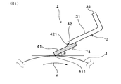
- FIG. 3 is an explanatory diagram schematically illustrating a usage state of the cleaning blade of Example 1.
- 3 is a side view schematically showing the cleaning blade of Example 1.
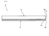
- FIG. 1 is a front view schematically showing a cleaning blade of Example 1.
- FIG. It is typical sectional drawing for demonstrating the detailed structure of a braid
- FIG. 10 is a side view schematically showing a cleaning blade of Example 3.
- FIG. 6 is a side view schematically showing a cleaning blade of Example 4.
- FIG. It is explanatory drawing for demonstrating the structure of the cleaning blade in an experiment example, (a) is the sample 13, (b) is the sample 14, (c) is the structure of the sample 15.
- the cleaning blade is used to remove residual toner remaining on the surface of the mating member by sliding contact with the mating member in the image forming apparatus employing an electrophotographic system.
- the image forming apparatus include image forming apparatuses such as a copying machine, a printer, a facsimile machine, a multifunction machine, and an on-demand printing machine that employ an electrophotographic system using a charged image.
- the counterpart member include an image carrier such as a photosensitive drum, an intermediate transfer belt, and the like.
- the intermediate transfer belt is used to primarily transfer the toner image carried on the image carrier to the belt, and then secondarily transfer the toner image from the belt to a transfer material such as paper.
- the cleaning blade is a sliding contact portion for sliding the edge portion of the tip of the blade portion into contact with the mating member, and is brought into contact with the surface of the mating member in operation, It can be used to scrape off and remove residual toner on the surface of the mating member that has been carried to the sliding contact portion.
- the cleaning blade has a support having a plate-like portion.
- the support can be composed of various metal materials.
- the plate-like portion can have, for example, a rectangular shape having a predetermined thickness, and can be configured such that the blade portion is joined to the distal end side in the short direction.
- the length of the plate-like portion is preferably 120 to 400 mm, more preferably 230 to 360 mm, and the length in the short direction is preferably 5 to 50 mm, more preferably 9 to 30 mm. be able to.
- the thickness of the plate-like portion is preferably 1 to 2.6 mm, more preferably 1.2 to 2 mm.
- the support body is connected to the plate-like portion, and can be configured to have an attachment portion for attachment to a member of the image forming apparatus. In this case, the support can be formed in a cross-sectional “L” shape.
- the cleaning blade has a polyurethane blade portion joined to the plate-like portion by integral molding.
- the term “joined by integral molding” means that the polyurethane material is cured and joined to the plate-like part when the blade part is formed.
- a primer layer may be formed on the surface of the plate-like portion.
- the blade portion can be made of, for example, polyurethane rubber, polyurethane elastomer, or the like from the viewpoint of being flexible and tough and advantageous in improving followability.
- the blade part has a plate-like blade body part and a reinforcing part.
- the blade body part is joined to the plate surface of the plate-like part.
- the blade main body portion can be configured such that the proximal end portion is joined to the plate surface on the mating member side in the plate-like portion.
- the free length of the joined blade body can be preferably 5 to 20 mm, more preferably 6 to 12 mm, and more preferably 7 to 10 mm.
- the thickness of the blade body can be preferably 1 to 2.2 mm, more preferably 1.5 to 2 mm.
- the free length of the blade body is the distance between the tip surface of the plate-like portion and the tip surface of the blade body.
- the thickness of the blade body can be uniform in the longitudinal direction, or only the central portion can be thinned, or only the central portion can be thickened. In either case, the longitudinal direction at the position of the blade tip surface can be used. It is a value measured at the center part of.
- the reinforcing part extends from the surface of the blade body part and is joined to the tip surface of the plate-like part.
- the reinforcing portion can be configured to extend from a plate surface opposite to the counterpart member side in the blade main body portion.
- the reinforcing portion has a curved surface that curves inward. Therefore, when the reinforcing portion is viewed in a cross section perpendicular to the longitudinal direction of the blade portion, the intersection of the curved line constituting the curved surface and the plate surface line constituting the plate surface of the blade main body portion is the X point, and the curved surface.
- the curved line is positioned below (inside) the XY straight line connecting the X point and the Y point. is doing.
- the point X corresponds to the position of the leading edge of the bending portion.
- the Y point corresponds to the position of the upper edge of the curved portion.
- the width of the reinforcing portion can be set within a range of 0.5 to 8 mm, for example. In this case, it is easy to ensure contact pressure and ensure follow-up, and a cleaning blade can be obtained that easily suppresses toner slippage during long-term use. Further, there is an advantage that the bonding strength can be easily improved by increasing the bonding area with the support.
- the width of the reinforcing portion is preferably 2 mm or more, more preferably 3 mm or more, and still more preferably 3.5 mm or more from the viewpoint of increasing the contact pressure and preventing curling.
- the width of the reinforcing portion is preferably 7 mm or less, more preferably 6 mm or less, and even more preferably 5 mm or less, from the viewpoint of improving followability.
- the width of the reinforcing part is a distance between the front end surface of the plate-like part and the front end edge of the reinforcing part.
- the height of the reinforcing portion can be set within a range of 0.5 to 5 mm, for example. In this case, it is easy to ensure contact pressure and ensure follow-up, and a cleaning blade can be obtained that easily suppresses toner slippage during long-term use. Further, there is an advantage that the bonding strength can be easily improved by increasing the bonding area with the support.
- the height of the reinforcing portion is preferably 0.7 mm or more, more preferably 0.8 mm or more, and still more preferably 0.9 mm or more, from the viewpoint of increasing the contact pressure and preventing turning.
- the height of the reinforcing portion is preferably 4 mm or less, more preferably 3 mm or less, and even more preferably 2 mm or less, from the viewpoint of improving followability.
- the height of the reinforcing portion is the distance between the plate surface on the opposite side to the counterpart member side in the blade main body portion and the upper end edge where the reinforcing portion intersects the tip surface of the plate-like portion.
- the tip thickness of the blade main body can be in the range of 0.7 to 3 mm. In this case, it is easy to ensure contact pressure and ensure follow-up, and a cleaning blade can be obtained that easily suppresses toner slippage during long-term use. Further, there is an advantage that it is easy to improve the bonding strength with the support.
- the tip thickness of the blade body is preferably 1 mm or more, more preferably 1.3 mm or more, still more preferably 1.5 mm or more, and even more preferably 1.8 mm or more, from the viewpoint of increasing the contact pressure and preventing curling. It can be. Further, the thickness of the tip of the blade main body is preferably 2.2 mm or less, more preferably 2.1 mm or less, and even more preferably 2 mm or less from the viewpoint of facilitating ensuring followability.
- the said reinforcement part can be specifically formed by the shaping
- the blade body portion may be configured such that the surface treatment is performed so that the coefficient of friction is lower than the inside of the blade body, or a film is formed on the surface.
- the surface of the blade main body is reduced in friction, it is easy to suppress toner slipping due to turning-up or abrasion of the blade main body. Therefore, in this case, a cleaning blade that easily suppresses toner slip-through can be obtained due to the synergistic effect of the blade portion being integrally formed and the reinforcing portion.
- the inside of a blade main body part means the part which is not surface-treated inside the surface treatment layer.
- the above surface treatment only needs to make the dynamic friction coefficient of the surface of the blade main body smaller than that inside.
- the ultraviolet ray irradiation treatment is performed to cure the ultraviolet curable resin, thereby forming a cured layer on the surface portion of the blade main body portion.
- the forming method can be given.
- Other examples of the surface treatment include, for example, a method of forming a hardened layer on the surface layer portion of the blade body by impregnating the blade body with a surface treatment liquid containing an isocyanate compound and performing heat treatment. Can do.
- the film is formed on the surface of the blade main body by chemical vapor deposition using a hydrocarbon gas that has been brought into a plasma state by microwaves, or a diamond-like carbon film by plasma CVD. Or the like can be formed.
- the dynamic friction coefficient of the blade body surface can be, for example, preferably 3.0 or less, more preferably 1.0 or less, and even more preferably 0.5 or less.
- the dynamic friction coefficient is measured as follows. The edge portion of the blade body is pressed against a metal plate member having a 150 ⁇ m thick PET sheet on the surface at a contact angle ⁇ of 25 ° and a contact pressure of 1 N / cm. Next, the plate member is moved to the contact angle forming side at a speed of 2.5 mm / second, and the dynamic friction coefficient is measured.
- the blade body may contain a conductive agent.
- the charge of the toner can be removed during cleaning. Therefore, in this case, the toner can be easily removed from the counterpart member such as the image carrier, and a cleaning blade advantageous in improving the cleaning property can be obtained.
- an ion conductive agent or an electronic conductive agent can be used as the conductive agent.
- the ionic conductive agent a liquid one and a solid one are known, but preferably a solid one can be suitably used at room temperature. This is because bleeding hardly occurs and it is difficult to contaminate a counterpart member such as an image carrier.
- Specific examples of the ionic conductive agent include quaternary ammonium salts, alkali metal salts, alkaline earth metal salts, and the like. More specifically, a potassium salt or the like can be suitably used as the ionic conductive agent.
- anion in the potassium salt examples include CF 3 SO 2 C 4 F 9 SO 2 N ⁇ , (CF 3 SO 2 ) 2 N ⁇ , (FSO 2 ) 2 N ⁇ , C 28 H 20 BO. 6 ⁇ , AlCl 4 ⁇ , Al 2 Cl 7 ⁇ , NO 3 ⁇ , BF 4 ⁇ , PF 6 ⁇ , CH 3 COO ⁇ , CF 3 COO ⁇ , CF 3 SO 3 ⁇ , (CF 3 SO 2 ) 3 C ⁇ , AsF 6 ⁇ , SbF 6 ⁇ , F (HF) N ⁇ , CF 3 CF 2 CF 2 CF 2 SO 3 ⁇ , (CF 3 CF 2 SO 2 ) 2 N ⁇ , CF 3 CF 2 CF 2 COO ⁇ , ( Examples thereof include C 4 F 9 SO 2 ) 2 N ⁇ , CF 2 (CF 2 SO 2 ) 2 N ⁇ , CF 3 SO 2 NH 2 —
- the blade body may contain fine particles, and the fine particles may have a convex portion formed on the surface.
- the fine particles may have a convex portion formed on the surface.
- it is possible to reduce the contact area between the surface of the counterpart member and the blade body while suppressing toner slipping. Therefore, in this case, it is easy to reduce the frictional force acting between the mating member, which is advantageous for reducing the friction.
- it can also contribute to the improvement of the wear resistance of the blade body.
- Part of the fine particles may be exposed on the surface of the blade body.
- the fine particles particles having a nano size of 1 ⁇ m or less can be suitably used.
- the average particle diameter of the fine particles can be, for example, 1 to 900 nm, preferably 5 to 700 nm, and more preferably 10 to 500 nm.
- the average particle diameter is an average value of the particle diameters of 10 fine particles from the largest when the cross section of the blade body is observed with a scanning electron microscope.
- the material of the fine particles may be either inorganic or organic.
- Specific examples of the fine particles include silica particles, alumina particles, and metal particles.
- the metal constituting the metal particles include Au, Ag, Ni, Mn, and alloys thereof. These can be used alone or in combination of two or more.
- the plate-like blade main body may be joined substantially parallel to the plate surface of the plate-like portion, or may be joined so as to be inclined with respect to the plate surface of the plate-like portion. .
- the cleaning blade since the blade portion is joined to the plate-like portion by integral molding and has the reinforcing portion, it is easy to finely adjust the angle of the blade portion with respect to the plate surface of the plate-like portion as described above. Therefore, the cleaning blade can easily set the contact angle according to the model of the image forming apparatus, and can improve the degree of freedom of attachment.
- the cleaning blade has high bonding properties because the blade portion is joined to the plate-like portion by integral molding and has the reinforcing portion. Therefore, the cleaning blade is advantageous for designing the blade body portion to be thin.
- the plate surface on the opposite side to the counterpart member side in the blade main body portion can be arranged in the same plane as the extended surface of the plate surface on the counterpart member side in the plate-like portion.
- the plate surface on the opposite side to the mating member side in the blade main body is an extension surface of the plate surface on the mating member side in the plate-like portion and an extension of the plate surface on the opposite side to the mating member side in the plate-like portion. It can also be arranged between the surfaces. In the latter case, it is advantageous to design a thin blade body.
- the thickness of the blade body portion can be finely controlled.
- the thickness of the blade body part may be constant in the longitudinal direction of the blade body part, the thickness of the center part in the longitudinal direction may be formed thicker than both end parts, or the center in the longitudinal direction The thickness of the part may be formed thinner than both end parts.
- Example 1 The cleaning blade of Example 1 will be described with reference to FIGS.
- the cleaning blade 2 of this example removes residual toner (not shown) remaining on the surface of the counterpart member 1 by sliding contact with the counterpart member 1 in an image forming apparatus that employs an electrophotographic system.
- the counterpart member 1 is a photosensitive drum which is an image carrier.
- the cleaning blade 2 is a sliding contact portion for allowing the edge portion 411 at the tip of the blade portion 4 to come into sliding contact with the mating member 1.
- ⁇ is the contact angle.
- An arrow Y indicates the rotation direction of the photosensitive drum which is an image carrier.
- the cleaning blade 2 of this example has a support 3 having a plate-like portion 31 and a blade portion 4 made of polyurethane.
- the blade part 4 is joined to the plate-like part 31 by integral molding.
- the support 3 further has an attachment portion 32 connected to the plate-like portion 31.
- the attachment part 32 is a part for attaching to the cartridge of the image forming apparatus.
- the support 3 is formed in a long shape with a metal material, and the plate-like portion 31 and the attachment portion 32 are both formed in a rectangular shape having a predetermined thickness.
- the attachment portion 32 protrudes from the base end portion of the plate-like portion 31 in a direction perpendicular to the plate surface of the plate-like portion 31.
- the support 3 is formed in a cross-sectional “L” shape.
- the plate-like portion 31 has a length of 354 mm in the longitudinal direction, a length in the short direction of 15 mm, and a thickness of 2 mm.
- the blade part 4 has a plate-like blade body part 41 and a reinforcing part 42.
- the blade main body 41 is joined to the plate surface of the plate-like portion 3.
- the blade main body 41 is joined substantially parallel to the plate surface of the plate-like portion 31.
- the plate surface on the opposite side to the counterpart member 1 side in the blade main body 41 is disposed substantially in the same plane as the extended surface of the plate surface on the counterpart member 1 side in the plate-like portion 31.
- the blade main body 41 has a proximal end portion joined to a plate surface of the plate-like portion 31 on the counterpart member 1 side.
- the reinforcing part 42 extends from the surface of the blade body part 41 and is joined to the tip surface of the plate-like part 31. In this example, specifically, the reinforcing portion 42 extends from the plate surface on the opposite side of the blade main body portion 41 from the counterpart member 1 side.
- the reinforcing portion 42 has a curved surface 421 that curves inward. Therefore, as shown in FIG. 4, when viewed in a cross section perpendicular to the longitudinal direction of the blade portion 4, the reinforcing portion 42 curves downward (inward) from the XY straight line connecting the X point and the Y point.
- a curved line 421a constituting the surface 421 is located.
- point X corresponds to the position of the leading edge of the bending portion 42, and is the intersection of the bending line 421 a forming the bending surface 421 and the plate surface line 41 a forming the plate surface of the blade body 41.
- the point Y is an intersection of the curved line 421a constituting the curved surface 421 and the distal end line 31a constituting the distal end surface of the plate-like portion 31. That is, it can be said that the reinforcing portion 42 has an R shape such that the curved line 421a is convex downward.
- the width W of the reinforcing portion 42 shown in FIG. 4 is specifically in the range of 0.5 to 8 mm.
- the height H of the reinforcing portion 42 is in the range of 0.5 to 5 mm.
- the tip thickness t of the blade body 41 is in the range of 0.7 to 3 mm.
- the free length L of the blade body 41 is in the range of 5 to 20 mm.
- the joining length BWL between the blade body 41 and the plate-like part 31 of the support 3 is in the range of 1.5 to 7 mm.
- the thickness of the blade body 41 is constant in the longitudinal direction of the blade body 41.
- the blade body 41 is formed such that the thickness of the central portion in the longitudinal direction is thicker than both end portions, or the thickness of the central portion in the longitudinal direction as illustrated in FIG. 6. May be formed thinner than both ends.
- Example 2 The cleaning blade of Example 2 will be described with reference to FIG. As shown in FIG. 7, the cleaning blade 2 of this example is joined so that the blade body 41 is inclined with respect to the plate surface of the plate-like portion 31.
- the inclination direction is a direction in which the tip of the blade body 31 is separated from the counterpart member 1.
- the cleaning blade 2 according to the second embodiment is an example in the case where it is compatible with a model different from the image forming apparatus according to the first embodiment. Other configurations are the same as those of the first embodiment.
- Example 3 The cleaning blade of Example 3 will be described with reference to FIG. As shown in FIG. 8, the cleaning blade 2 of this example is joined so that the blade body 41 is inclined with respect to the plate surface of the plate-like portion 31. Specifically, the inclination direction is a direction in which the tip of the blade body 41 approaches the counterpart member 1.
- the cleaning blade 2 of this example is an example in the case where it corresponds to a different model from the image forming apparatuses of the first and second embodiments. Other configurations are the same as those of the first embodiment.
- Example 4 The cleaning blade of Example 4 will be described with reference to FIG.
- the plate surface on the opposite side to the counterpart member 1 side in the blade main body 41 is an extended surface of the plate surface on the counterpart member 1 side in the plate-like portion 31. It arrange
- the cleaning blade 2 of this example is an example in which the thickness of the blade body 41 is formed thinner than the cleaning blade 2 of the first embodiment. Other configurations are the same as those of the first embodiment.
- a curing agent liquid was prepared by mixing 13 parts by mass of a low molecular weight polyol and 0.01 parts by mass of triethylenediamine (manufactured by Tosoh Corporation) as a catalyst in a nitrogen atmosphere at 80 ° C. for 1 hour.
- the above-prepared main agent liquid and curing agent liquid were mixed for 3 minutes at 60 ° C. in a vacuum atmosphere at a blending ratio of 94 parts by mass of the curing agent liquid with respect to 100 parts by mass of the main agent liquid, and sufficiently degassed. Thereby, a urethane composition (1) was prepared.
- the urethane composition (1) is used for preparing cleaning blades for samples 1 to 10 and 13 to 15.
- urethane composition (1) In the preparation of the urethane composition (1), the same except that 10 parts by mass of silica fine particles (average particle size: 200 nm, manufactured by Core Front Co., Ltd., “SICASSTAR 43-00-202”) was added to 100 parts by mass of the main agent liquid. Thus, a urethane composition (2) was prepared. The urethane composition (2) is used for producing a cleaning blade of the sample 11.
- a urethane composition was prepared in the same manner except that 10 parts by mass of an ionic conductive agent (manufactured by Mitsubishi Materials Electronics Kasei Co., Ltd., “EF-12”) was added to 100 parts by mass of the main agent liquid. (3) was prepared. The urethane composition (3) is used for preparing a cleaning blade of the sample 12.
- an ionic conductive agent manufactured by Mitsubishi Materials Electronics Kasei Co., Ltd., “EF-12”
- a predetermined urethane composition was injected into a cavity in a predetermined mold on which the support was set, and was cured by heating at 130 ° C. for 10 minutes. After curing, it was removed from the mold. As a result, cleaning blades of Samples 1 to 9, 11, and 12 were obtained. Further, in the production of the cleaning blade of the sample 10, the cured layer was formed by surface-treating the surface of the formed blade portion with a surface treatment liquid.
- the surface treatment liquid is an isocyanate-based surface treatment liquid, and specifically contains polyisocyanate, a polymerization catalyst, and an organic solvent. Specifically, the surface treatment was performed by immersing the blade portion in the surface treatment solution for 30 minutes, and then removing the blade portion from the surface treatment solution and heating at 120 ° C.
- the reinforcing portion forming material 921 was joined to the plate surface of the blade portion 92 and the front end surface of the plate-like portion 31 by using a primer and a hot melt adhesive 920 to form a reinforcing portion.
- a cleaning blade for Sample 14 was produced.
- Table 1 shows the detailed configuration and evaluation results of the cleaning blade of each sample produced.
- the cleaning blades for Sample 1 to Sample 12 have a blade portion joined to the plate-like portion of the support by integral molding. And this blade part has a reinforcement part other than a blade main-body part. Therefore, the thickness of the blade portion on the base end side (cross-sectional area) of the blade portion is increased by the reinforcing portion, and the rigidity is increased. Therefore, the cleaning blade can increase the contact pressure by the blade portion without changing the design to bring the cleaning blade closer to the photosensitive drum as the counterpart member.
- the reinforcing portion extends from the surface of the blade body, it is integrally connected to the blade body. Further, since the reinforcing portion is a curved surface whose outer surface is curved inward, the curved surface smoothly transitions to the surface of the blade main body portion at the distal end edge of the reinforcing portion. For this reason, the reinforcing portion can disperse the force as a whole, and it is difficult for stress to concentrate on the tip edge of the reinforcing portion. Therefore, when the blade portion is in sliding contact with the mating member, the blade main body portion is unlikely to bend at the tip end edge portion of the reinforcing portion, and the contact angle is likely to be kept large. Therefore, the cleaning blade can ensure good followability to the surface of the photosensitive drum, which is the counterpart member.
- the cleaning blade increases the contact pressure without changing the design to approach the photosensitive drum, which is the counterpart member, and ensures good followability to the surface of the photosensitive drum. It can be seen that it is possible to suppress this.
- the cleaning blades of Samples 10 to 12 were less contaminated with the photosensitive drum than the cleaning blades of Samples 1 to 9. This is because the surface treatment for reducing friction and the addition of fine particles and a conductive agent to the blade main body improve the sliding property of the blade main body (surface treatment, addition of fine particles), This is because the removal performance of the toner (the addition of a conductive agent) has made it easier for the toner scraping ability to be exhibited over a long period of time.
- the cleaning blade of the sample 13 has no reinforcing portion in the blade portion.
- the contact pressure becomes insufficient, and toner slips out during durability, which causes image defects in streak images.
- the cleaning blades of the samples 14 and 15 have the reinforcing part, the reinforcing part does not have a curved surface. As a result, the followability is lowered, and the toner slips out during the endurance, which causes the image defect of the streak image.
Landscapes
- Physics & Mathematics (AREA)
- General Physics & Mathematics (AREA)
- Cleaning In Electrography (AREA)
Abstract
相手部材(1)側へ近づける設計変更をすることなく当接圧を高めるとともに、相手部材(1)表面に対する良好な追従性を確保することにより、長期使用時にトナーのすり抜けを抑制可能なクリーニングブレード(2)を提供する。クリーニングブレード(2)は、電子写真方式を採用する画像形成装置内の相手部材(1)との摺接によって相手部材(1)の表面に残留する残留トナーを除去するために用いられる。クリーニングブレード(2)は、板状部(31)を有する支持体(3)と、板状部(31)に一体成形によって接合されたポリウレタン製のブレード部(4)とを有している。ブレード部(4)は、板状部(31)の板面に接合された板状のブレード本体部(41)と、ブレード本体部(41)の表面から延びるとともに板状部(31)の先端面に接合された補強部(42)とを有している。補強部(42)は、内方に湾曲する湾曲面(421)を有している。
Description
本発明は、クリーニングブレードに関し、さらに詳しくは、電子写真方式の画像形成装置に用いられるクリーニングブレードに関する。
電子写真方式の画像形成装置では、例えば、感光体等の像担持体や中間転写ベルトの表面をクリーニングするためにクリーニングブレードが用いられている。クリーニングブレードは、ブレード部における先端のエッジ部が、相手部材である像担持体や中間転写ベルトの表面に押し付けられている。相手部材とエッジ部との摺接により、相手部材表面に残留する残留トナーが掻き取られて除去される。
従来のクリーニングブレードとしては、例えば、板状部を有する金属製の支持体と、板状部における先端側の片面に、プライマー、ホットメルト接着剤を介して接着された板状のポリウレタンからなるブレード部とを有するクリーニングブレードが広く知られている。
また例えば、特許文献1には、ブレード部の板面と支持板の先端面との両方に補強弾性体を接合したクリーニングブレードが提案されている。同文献において、補強弾性体は、断面三角形状、断面台形状の形状を有している。
近年、画像形成装置は、高速化されてきている。画像形成装置が高速化されると、像担持体や中間転写ベルトの回転速度が上がる。そのため、従来広く知られるクリーニングブレードは、相手部材表面を押さえ付ける当接圧が従来の設定のままで使用されると、当接圧の不足によりトナーのすり抜けが発生する。特に、最近では、高画質化の要請から、球形かつ小径のトナーが使用されるようになっている。そのため、相手部材表面とブレード部のエッジ部との間に僅かな隙間が生じてもトナーがすり抜けてしまう状況にある。
上記問題に対処するため、従来よりも相手部材側に近づくようにクリーニングブレードの位置を変更することにより、ブレード部による当接圧を高める方法が考えられる。しかしながら、この方法によると、ブレード部と相手部材との摩擦力が大きくなり、ブレード部の先端がめくれてしまう。ブレード部がめくれた状態でクリーニングが続けられると、ブレード部の側面に局所的な摩耗が生じ、場合によっては、この摩耗が進行してブレード部の先端が欠けることもある。そのため、上記方法によると、近年求められている画像形成装置の高耐久化に対応することができない。よって、クリーニングブレードを従来よりも相手部材側へ近づける設計変更をすることなく、ブレード部による当接圧を高めることが必要になる。
ブレード部による当接圧を単純に高める方法として、特許文献1に提案される方法がある。しかしながら、ブレード部の板面と支持板の先端面との両方に断面三角形状等の補強弾性体が接合されたクリーニングブレードは、次の問題がある。
すなわち、この種のクリーニングブレードは、断面形状が局所的に大きく変化する補強弾性体の先端縁に応力が集中しやすい。そのため、ブレード部は、相手部材との摺接時に、補強弾性体の先端縁部分にてブレード部が曲がりやすく、相手部材表面とブレード部との間の当接角が小さくなりやすい。つまり、上記クリーニングブレードは、単純に当接圧を高めたことによってかえって相手部材表面に対する追従性が低下し、その結果として、長期使用時にトナーのすり抜けが生じてしまう。
本発明は、上記背景に鑑みてなされたものであり、相手部材側へ近づける設計変更をすることなく当接圧を高めるとともに、相手部材表面に対する良好な追従性を確保することにより、長期使用時にトナーのすり抜けを抑制可能なクリーニングブレードを提供しようとするものである。
本発明の一態様は、電子写真方式を採用する画像形成装置内の相手部材との摺接によって上記相手部材の表面に残留する残留トナーを除去するために用いられるクリーニングブレードであって、
板状部を有する支持体と、上記板状部に一体成形によって接合されたポリウレタン製のブレード部とを有しており、
上記ブレード部は、上記板状部の板面に接合された板状のブレード本体部と、上記ブレード本体部の表面から延びるとともに上記板状部の先端面に接合された補強部とを有しており、
上記補強部は、内方に湾曲する湾曲面を有していることを特徴とするクリーニングブレードにある。
板状部を有する支持体と、上記板状部に一体成形によって接合されたポリウレタン製のブレード部とを有しており、
上記ブレード部は、上記板状部の板面に接合された板状のブレード本体部と、上記ブレード本体部の表面から延びるとともに上記板状部の先端面に接合された補強部とを有しており、
上記補強部は、内方に湾曲する湾曲面を有していることを特徴とするクリーニングブレードにある。
上記クリーニングブレードは、支持体の板状部に一体成形によって接合されたブレード部を有している。そして、このブレード部は、上記ブレード本体部以外にも上記補強部を有している。そのため、ブレード部は、補強部によりブレード部の基端側における厚み(断面積)が増し、剛性が高くなる。それ故、上記クリーニングブレードは、相手部材側へ近づける設計変更をしなくても、ブレード部による当接圧を高めることが可能となる。
さらに、上記補強部は、ブレード本体部の表面から延びているため、ブレード本体部と一体的に繋がっている。また、補強部は、外表面が内方に湾曲する湾曲面とされているので、補強部の先端縁においてその湾曲面がブレード本体部の表面に滑らかに移行する。そのため、補強部は、全体で力を分散させることが可能であり、補強部の先端縁に応力が集中し難い。そのため、ブレード部は、相手部材との摺接時に、補強部の先端縁部分にてブレード本体部が曲がり難く、当接角を大きく保持しやすい。それ故、上記クリーニングブレードは、相手部材表面に対する良好な追従性を確保することが可能となる。
したがって、上記クリーニングブレードは、相手部材側へ近づける設計変更をすることなく当接圧を高めるとともに、相手部材表面に対する良好な追従性を確保することにより、長期使用時にトナーのすり抜けを抑制することができる。
上記クリーニングブレードは、電子写真方式を採用する画像形成装置内の相手部材との摺接によって相手部材の表面に残留する残留トナーを除去するために用いられる。画像形成装置としては、具体的には、帯電像を用いる電子写真方式を採用する複写機、プリンター、ファクシミリ、複合機、オンデマンド印刷機等の画像形成装置を例示することができる。また、相手部材としては、感光ドラム等の像担持体や中間転写ベルトなどを例示することができる。なお、中間転写ベルトは、像担持体に担持されたトナー像を当該ベルトに一次転写した後、このトナー像を当該ベルトから用紙等の転写材へ二次転写するためのものである。上記クリーニングブレードは、より具体的には、ブレード部の先端のエッジ部が相手部材と摺接させるための摺接部とされ、動作する相手部材の表面に摺り合った状態で接触させることにより、摺接部まで運ばれてきた相手部材表面の残留トナーを掻き取って除去するように使用することができる。
上記クリーニングブレードは、板状部を有する支持体を有している。支持体は、各種の金属材料などから構成することができる。板状部は、具体的には、例えば、所定の厚みを有する長方形状の形状を有することができ、短手方向の先端側にブレード部が接合されるように構成することができる。この場合、板状部は、長手方向の長さを、好ましくは120~400mm、より好ましくは230~360mm、短手方向の長さを、好ましくは5~50mm、より好ましくは9~30mmとすることができる。また、板状部の厚みは、好ましくは1~2.6mm、より好ましくは1.2~2mmとすることができる。支持体は、より具体的には、例えば、板状部と繋がっており、画像形成装置の部材に取り付けるための取付部を有する構成とすることができる。この場合、支持体は、断面「L」字状に形成することができる。
上記クリーニングブレードは、板状部に一体成形によって接合されたポリウレタン製のブレード部を有している。上記「一体成形によって接合される」とは、ブレード部の形成時にポリウレタン材料の硬化とともに板状部に接合されることを意味する。なお、板状部の表面には、プライマー層が形成されていてもよい。ブレード部は、具体的には、例えば、柔軟で靱性があり、追従性の向上に有利である等の観点から、ポリウレタンゴム、ポリウレタンエラストマーなどから構成することができる。
ブレード部は、板状のブレード本体部と補強部とを有している。ブレード部において、ブレード本体部は、板状部の板面に接合されている。ブレード本体部は、具体的には、基端側の部分が、板状部における相手部材側の板面に接合される構成とすることができる。なお、接合されたブレード本体部の自由長は、好ましくは5~20mm、より好ましくは6~12mm、より好ましくは7~10mmとすることができる。また、ブレード本体部の厚みは、好ましくは1~2.2mm、より好ましくは1.5~2mmとすることができる。なお、ブレード本体部の自由長は、板状部の先端面とブレード本体部の先端面との間の距離である。ブレード本体部の厚みは、長手方向で均一としたり、中央部のみを薄くしたり、中央部のみを厚くしたりすることが可能であるが、いずれの場合も、ブレード先端面の位置における長手方向の中央部で測定される値である。
ブレード部において、補強部は、ブレード本体部の表面から延びるとともに板状部の先端面に接合されている。補強部は、具体的には、ブレード本体部における相手部材側と反対側の板面から延びる構成とすることができる。ここで、補強部は、内方に湾曲する湾曲面を有している。したがって、補強部は、ブレード部の長手方向に垂直な断面で見た場合に、湾曲面を構成する湾曲ラインとブレード本体部の板面を構成する板面ラインとの交点をX点、湾曲面を構成する湾曲ラインと板状部の先端面を構成する先端ラインとの交点をY点とした場合に、X点とY点とを結ぶXY直線よりも下方(内側)に、湾曲ラインが位置している。なお、X点は、湾曲部の先端縁の位置に対応している。Y点は、湾曲部の上端縁の位置に対応している。
補強部の幅は、具体的には、例えば、0.5~8mmの範囲内とすることができる。この場合には、当接圧の向上、追従性の確保を確実なものとしやすく、長期使用時にトナーのすり抜けを抑制しやすいクリーニングブレードが得られる。また、支持体との接合面積の増加により接合強度を向上させやすくなるなどの利点もある。補強部の幅は、当接圧の増加、めくれ防止等の観点から、好ましくは2mm以上、より好ましくは3mm以上、さらに好ましくは3.5mm以上とすることができる。また、補強部の幅は、追従性の向上等の観点から、好ましくは7mm以下、より好ましくは6mm以下、さらに好ましくは5mm以下とすることができる。なお、補強部の幅は、板状部の先端面と補強部の先端縁との間の距離である。
補強部の高さは、具体的には、例えば、0.5~5mmの範囲内とすることができる。この場合には、当接圧の向上、追従性の確保を確実なものとしやすく、長期使用時にトナーのすり抜けを抑制しやすいクリーニングブレードが得られる。また、支持体との接合面積の増加により接合強度を向上させやすくなるなどの利点もある。補強部の高さは、当接圧の増加、めくれ防止等の観点から、好ましくは0.7mm以上、より好ましくは0.8mm以上、さらに好ましくは0.9mm以上とすることができる。また、補強部の高さは、追従性の向上等の観点から、好ましくは4mm以下、より好ましくは3mm以下、さらに好ましくは2mm以下とすることができる。なお、補強部の高さは、ブレード本体部における相手部材側と反対側の板面と、補強部が板状部の先端面と交わる上端縁との間の距離である。
上記クリーニングブレードにおいて、ブレード本体部の先端厚みは、0.7~3mmの範囲内とすることができる。この場合には、当接圧の向上、追従性の確保を確実なものとしやすく、長期使用時にトナーのすり抜けを抑制しやすいクリーニングブレードが得られる。また、支持体との接合強度を向上させやすくなるなどの利点もある。ブレード本体部の先端厚みは、当接圧の増加、めくれ防止等の観点から、好ましくは1mm以上、より好ましくは1.3mm以上、さらに好ましくは1.5mm以上、さらにより好ましくは1.8mm以上とすることができる。また、ブレード本体部の先端厚みは、追従性を確保しやすくなる等の観点から、好ましくは2.2mm以下、より好ましくは2.1mm以下、さらに好ましくは2mm以下とすることができる。
なお、上記補強部は、具体的には、例えば、ブレード部の一体成形時に用いられる成形型や、研磨加工などによって形成することが可能である。
上記クリーニングブレードにおいて、ブレード本体部は、その内部に比べて摩擦係数が低くなるように表面処理が施されている、または、表面に被膜が形成されている構成とするすることができる。この場合には、ブレード本体部の表面が低摩擦化されるので、ブレード本体部のめくれや摩耗によるトナーのすり抜けを抑制しやすくなる。したがって、この場合には、ブレード部が一体成形されていることと、上記補強部を有することとの相乗効果により、トナーのすり抜けを抑制しやすいクリーニングブレードが得られる。なお、ブレード本体部の内部とは、表面処理層よりも内方側の表面処理が施されていない部分をいう。
上記表面処理は、ブレード本体部の表面の動摩擦係数がその内部に比べて小さくできればよい。上記表面処理としては、具体的には、例えば、紫外線硬化樹脂をブレード本体部に含浸させた後、紫外線照射処理して紫外線硬化樹脂を硬化させることにより、ブレード本体部の表面部分に硬化層を形成する方法などを例示することができる。上記表面処理としては、他にも例えば、イソシアネート化合物を含有する表面処理液をブレード本体部に含浸させ、熱処理することにより、ブレード本体部の表層部分に硬化層を形成する方法などを例示することができる。また、上記被膜は、具体的には、例えば、マイクロ波によりプラズマ状態とした炭化水素ガスを用いた化学気相蒸着によってブレード本体部の表面に成膜したり、プラズマCVD法によってダイヤモンドライクカーボン膜等を成膜したりして形成することができる。
上記クリーニングブレードにおいて、ブレード本体部表面の動摩擦係数は、具体的には、例えば、好ましくは3.0以下、より好ましくは1.0以下、さらに好ましくは0.5以下とすることができる。なお、上記動摩擦係数は、次のようにして測定される。表面に厚み150μmのPETシートが配置された金属製の板部材に、ブレード本体部のエッジ部を、当接角θ:25°、当接圧:1N/cmで押し当てる。次いで、当接角の形成側に板部材を2.5mm/秒の速度で移動させ、動摩擦係数を測定する。
上記クリーニングブレードにおいて、ブレード本体部は、導電剤を含有する構成とすることができる。この場合には、ブレード本体部が導電化されるため、クリーニング時にトナーの電荷を除電することが可能となる。そのため、この場合には、像担持体等の相手部材からトナーがとれやすくなり、クリーニング性の向上に有利なクリーニングブレードが得られる。
上記導電剤としては、具体的には、イオン導電剤、電子導電剤を用いることができる。イオン導電剤としては、液体のものと固体のものが知られているが、好ましくは、常温で固体のものを好適に用いることができる。ブリードが生じ難く、像担持体等の相手部材を汚染し難いためである。イオン導電剤としては、具体的には、例えば、4級アンモニウム塩、アルカリ金属塩、アルカリ土類金属塩などを例示することができる。イオン導電剤としては、より具体的には、カリウム塩などを好適に用いることができる。カリウム塩におけるアニオンとしては、具体的には、例えば、CF3SO2C4F9SO2N-、(CF3SO2)2N-、(FSO2)2N-、C28H20BO6
-、AlCl4
-、Al2Cl7
-、NO3
-、BF4
-、PF6
-、CH3COO-、CF3COO-、CF3SO3
-、(CF3SO2)3C-、AsF6
-、SbF6
-、F(HF)N-、CF3CF2CF2CF2SO3
-、(CF3CF2SO2)2N-、CF3CF2CF2COO-、(C4F9SO2)2N-、CF2(CF2SO2)2N-、CF3SO2NH2
-などを例示することができる。また、電子導電剤としては、例えば、カーボンブラック、金属酸化物の微粒子などを例示することができる。
上記クリーニングブレードにおいて、ブレード本体部は、微粒子を含有しており、該微粒子によって表面に凸部が形成されている構成とすることができる。この場合には、トナーのすり抜けを抑制しつつ、相手部材の表面とブレード本体部との接触面積を少なくすることができる。そのため、この場合には、相手部材との間に作用する摩擦力を小さくしやすく、低摩擦化に有利である。また、ブレード本体部の耐摩耗性の向上にも寄与することができる。なお、上記微粒子は、ブレード本体部の表面に一部が露出していてもよい。
上記微粒子は、1μm以下のナノサイズの大きさを有する粒子を好適に用いることができる。上記微粒子の平均粒子径は、具体的には、例えば、1~900nm、好ましくは5~700nm、より好ましくは10~500nmとすることができる。なお、上記平均粒子径は、ブレード本体部の断面を走査型電子顕微鏡にて観察し、大きいものから10個の微粒子の粒子径の平均値である。また、微粒子の材質は、無機、有機のいずれであってもよい。微粒子としては、具体的には、例えば、シリカ粒子、アルミナ粒子、金属粒子などを例示することができる。金属粒子を構成する金属としては、Au、Ag、Ni、Mn、これらの合金などを例示することができる。これらは1種または2種以上併用することができる。
上記クリーニングブレードにおいて、板状のブレード本体部は、板状部の板面とほぼ平行に接合されていてもよいし、板状部の板面に対して傾斜するように接合されていてもよい。上記クリーニングブレードは、ブレード部が板状部に一体成形によって接合されるとともに上記補強部を有しているので、上記のように板状部の板面に対するブレード部の角度を微調整しやすい。それ故、上記クリーニングブレードは、画像形成装置の機種に応じて当接角の設定を行いやすく、取り付け自由度を向上させることができる。
また、上記クリーニングブレードは、ブレード部が板状部に一体成形によって接合されるとともに上記補強部を有しているので、接合性が高い。そのため、上記クリーニングブレードは、ブレード本体部の厚みを薄く設計するのに有利である。ブレード本体部における相手部材側と反対側の板面は、板状部における相手部材側の板面の延長面と同一面内に配置することができる。それ以外にも、ブレード本体部における相手部材側と反対側の板面は、板状部における相手部材側の板面の延長面と、板状部における相手部材側と反対側の板面の延長面との間に配置することもできる。後者の場合には、ブレード本体部の厚みを薄く設計するのに有利である。
また、上記クリーニングブレードは、ブレード部が一体成形されたものであるため、ブレード本体部の厚みを細かく制御可能である。例えば、ブレード本体部の厚みは、ブレード本体部の長手方向で一定とされていてもよいし、長手方向の中央部の厚みが両端部よりも厚く形成されていてもよいし、長手方向の中央部の厚みが両端部よりも薄く形成されていてもよい。
なお、上述した各構成は、上述した各作用効果等を得るなどのために必要に応じて任意に組み合わせることができる。
以下、実施例のクリーニングブレードについて、図面を用いて説明する。
(実施例1)
実施例1のクリーニングブレードについて、図1~図6を用いて説明する。図1に示されるように、本例のクリーニングブレード2は、電子写真方式を採用する画像形成装置内の相手部材1との摺接によって相手部材1の表面に残留する残留トナー(不図示)を除去するために用いられる。本例では、相手部材1は、像担持体である感光ドラムである。また、クリーニングブレード2は、ブレード部4の先端のエッジ部411が相手部材1と摺接させるための摺接部とされる。図1中、θは当接角である。また、矢印Yは、像担持体である感光ドラムの回転方向を示している。
実施例1のクリーニングブレードについて、図1~図6を用いて説明する。図1に示されるように、本例のクリーニングブレード2は、電子写真方式を採用する画像形成装置内の相手部材1との摺接によって相手部材1の表面に残留する残留トナー(不図示)を除去するために用いられる。本例では、相手部材1は、像担持体である感光ドラムである。また、クリーニングブレード2は、ブレード部4の先端のエッジ部411が相手部材1と摺接させるための摺接部とされる。図1中、θは当接角である。また、矢印Yは、像担持体である感光ドラムの回転方向を示している。
図2~図4に示されるように、本例のクリーニングブレード2は、板状部31を有する支持体3と、ポリウレタン製のブレード部4とを有している。ブレード部4は、板状部31に一体成形によって接合されている。本例では、支持体3は、板状部31と繋がる取付部32をさらに有している。取付部32は、画像形成装置のカートリッジに取り付けるための部位である。支持体3は、金属材料により長尺状に形成されており、板状部31および取付部32は、いずれも所定の厚みを有する長方形状に形成されている。取付部32は、板状部31の基端部から板状部31の板面と垂直な方向に突出している。したがって、本例では、支持体3は、断面「L」字状に形成されている。なお、板状部31は、長手方向の長さが354mm、短手方向の長さが15mmの大きさとされており、厚みは2mmとされている。
ブレード部4は、板状のブレード本体部41と、補強部42とを有している。ブレード本体部41は、板状部3の板面に接合されている。本例では、具体的には、ブレード本体部41は、板状部31の板面とほぼ平行に接合されている。ブレード本体部41における相手部材1側と反対側の板面は、板状部31における相手部材1側の板面の延長面とほぼ同一面内に配置されている。ブレード本体部41は、基端側の部分が、板状部31における相手部材1側の板面に接合されている。補強部42は、ブレード本体部41の表面から延びており、板状部31の先端面に接合されている。本例では、具体的には、補強部42は、ブレード本体部41における相手部材1側と反対側の板面から延びている。
ここで、補強部42は、内方に湾曲する湾曲面421を有している。したがって、図4に示されるように、ブレード部4の長手方向に垂直な断面で見た場合に、補強部42は、X点とY点とを結ぶXY直線よりも下方(内側)に、湾曲面421を構成する湾曲ライン421aが位置している。なお、X点は、湾曲部42の先端縁の位置に対応しており、湾曲面421を構成する湾曲ライン421aとブレード本体部41の板面を構成する板面ライン41aとの交点である。また、Y点は、湾曲面421を構成する湾曲ライン421aと板状部31の先端面を構成する先端ライン31aとの交点である。つまり、補強部42は、湾曲ライン421aが下に凸となるようなR形状を有しているといえる。
本例では、図4に示される補強部42の幅Wは、具体的には、0.5~8mmの範囲内とされる。同様に、補強部42の高さHは、0.5~5mmの範囲内とされる。ブレード本体部41の先端厚みtは、0.7~3mmの範囲内とされる。ブレード本体部41の自由長Lは、5~20mmの範囲内とされる。ブレード本体部41と支持体3の板状部31との接合長BWLは、1.5~7mmの範囲とされる。
なお、本例では、図3に示されるように、ブレード本体部41の厚みは、ブレード本体部41の長手方向で一定とされている。ブレード本体部41は、例えば、図5に例示されるように、長手方向の中央部の厚みが両端部より厚く形成されていたり、図6に例示されるように、長手方向の中央部の厚みが両端部より薄く形成されていてもよい。
(実施例2)
実施例2のクリーニングブレードについて、図7を用いて説明する。図7に示されるように、本例のクリーニングブレード2は、ブレード本体部41が、板状部31の板面に対して傾斜するように接合されている。傾斜方向は、ブレード本体部31の先端が相手部材1と離れる方向とされている。実施例2のクリーニングブレード2は、実施例1の画像形成装置と異なる機種に対応させる場合の例である。その他の構成は、実施例1と同様である。
実施例2のクリーニングブレードについて、図7を用いて説明する。図7に示されるように、本例のクリーニングブレード2は、ブレード本体部41が、板状部31の板面に対して傾斜するように接合されている。傾斜方向は、ブレード本体部31の先端が相手部材1と離れる方向とされている。実施例2のクリーニングブレード2は、実施例1の画像形成装置と異なる機種に対応させる場合の例である。その他の構成は、実施例1と同様である。
(実施例3)
実施例3のクリーニングブレードについて、図8を用いて説明する。図8に示されるように、本例のクリーニングブレード2は、ブレード本体部41が、板状部31の板面に対して傾斜するように接合されている。傾斜方向は、具体的には、ブレード本体部41の先端が相手部材1に近づく方向とされている。本例のクリーニングブレード2は、実施例1および実施例2の画像形成装置と異なる機種に対応させる場合の例である。その他の構成は、実施例1と同様である。
実施例3のクリーニングブレードについて、図8を用いて説明する。図8に示されるように、本例のクリーニングブレード2は、ブレード本体部41が、板状部31の板面に対して傾斜するように接合されている。傾斜方向は、具体的には、ブレード本体部41の先端が相手部材1に近づく方向とされている。本例のクリーニングブレード2は、実施例1および実施例2の画像形成装置と異なる機種に対応させる場合の例である。その他の構成は、実施例1と同様である。
(実施例4)
実施例4のクリーニングブレードについて、図9を用いて説明する。図9に示されるように、本例のクリーニングブレード2は、ブレード本体部41における相手部材1側と反対側の板面が、板状部31における相手部材1側の板面の延長面と、板状部31における相手部材1側と反対側の板面の延長面との間に配置されている。本例のクリーニングブレード2は、ブレード本体部41の厚みを、実施例1のクリーニングブレード2よりも薄く形成する場合の例である。その他の構成は、実施例1と同様である。
実施例4のクリーニングブレードについて、図9を用いて説明する。図9に示されるように、本例のクリーニングブレード2は、ブレード本体部41における相手部材1側と反対側の板面が、板状部31における相手部材1側の板面の延長面と、板状部31における相手部材1側と反対側の板面の延長面との間に配置されている。本例のクリーニングブレード2は、ブレード本体部41の厚みを、実施例1のクリーニングブレード2よりも薄く形成する場合の例である。その他の構成は、実施例1と同様である。
<実験例>
以下、実験例を用いてより具体的に説明する。
以下、実験例を用いてより具体的に説明する。
-ウレタン組成物の準備-
80℃にて1時間、真空脱泡したポリブチレンアジペート(PBA)(東ソー社製、「ニッポラン4010」):44質量部と、4,4′-ジフェニルメタンジイソシアネート(MDI)(東ソー社製、「ミリオネートMT」):56質量部とを混合し、窒素雰囲気下、80℃で3時間反応させることにより、ウレタンプレポリマーを含む主剤液を調製した。
80℃にて1時間、真空脱泡したポリブチレンアジペート(PBA)(東ソー社製、「ニッポラン4010」):44質量部と、4,4′-ジフェニルメタンジイソシアネート(MDI)(東ソー社製、「ミリオネートMT」):56質量部とを混合し、窒素雰囲気下、80℃で3時間反応させることにより、ウレタンプレポリマーを含む主剤液を調製した。
また、上記ポリブチレンアジペート(PBA):87質量部と、1,4-ブタンジオール(三菱化学社製)とトリメチロールプロパン(広栄パーストープ社製)とが重量比6:4にて混合されてなる低分子量ポリオール:13質量部と、触媒としてのトリエチレンジアミン(東ソー社製):0.01質量部とを、窒素雰囲気下、80℃にて1時間混合することにより、硬化剤液を調製した。
上記調製した主剤液と硬化剤液とを、主剤液100質量部に対して硬化剤液94質量部の配合割合にて、真空雰囲気下、60℃で3分間混合し、十分に脱泡した。これによりウレタン組成物(1)を調製した。ウレタン組成物(1)は、試料1~10、13~15のクリーニングブレードの作製に用いられる。
ウレタン組成物(1)の調製において、主剤液100質量部に対してシリカ微粒子(平均粒子径:200nm、コアフロント社製、「SICASTAR 43-00-202」)10質量部を添加した以外は同様にして、ウレタン組成物(2)を調製した。ウレタン組成物(2)は、試料11のクリーニングブレードの作製に用いられる。
ウレタン組成物(1)の調製において、主剤液100質量部に対してイオン導電剤(三菱マテリアル電子化成社製、「EF-12」)10質量部を添加した以外は同様にして、ウレタン組成物(3)を調製した。ウレタン組成物(3)は、試料12のクリーニングブレードの作製に用いられる。
-試料1~12のクリーニングブレードの作製-
図2に示されるように、断面「L」字状に折り曲げ形成された金属製の長尺板材からなる支持体を準備した。また、図4に示されるようなブレード部を形成可能なキャビティを有する各金型を準備した。なお、各金型は、ブレード本体部の長さ=354mm、ブレード本体部の幅BW=13mm、ブレード本体部の自由長L=8.6mm、ブレード本体部の厚み=2mm、表1に示される補強部の幅Wmm、補強部の高さHmm、および、ブレード本体部の先端厚みtmmを有する各ブレード部を形成可能な各キャビティを有している。
図2に示されるように、断面「L」字状に折り曲げ形成された金属製の長尺板材からなる支持体を準備した。また、図4に示されるようなブレード部を形成可能なキャビティを有する各金型を準備した。なお、各金型は、ブレード本体部の長さ=354mm、ブレード本体部の幅BW=13mm、ブレード本体部の自由長L=8.6mm、ブレード本体部の厚み=2mm、表1に示される補強部の幅Wmm、補強部の高さHmm、および、ブレード本体部の先端厚みtmmを有する各ブレード部を形成可能な各キャビティを有している。
次いで、支持体がセットされた所定の金型内のキャビティに所定のウレタン組成物を注入し、130℃で10分間加熱して硬化させた。硬化後、金型から取り出した。これにより、試料1~9、11、12のクリーニングブレードを得た。また、試料10のクリーニングブレードの作製では、形成されたブレード部の表面を表面処理液にて表面処理することにより、硬化層を形成した。なお、表面処理液は、イソシアネート系の表面処理液であり、具体的には、ポリイソシアネートと重合触媒と有機溶剤とを含んでいる。また、表面処理は、具体的には、ブレード部を表面処理液中に30分間浸漬させた後、ブレード部を表面処理液から取り出し、120℃で加熱することにより行った。
-試料13のクリーニングブレードの作製-
試料1のクリーニングブレードの作製において、図10(a)に示されるように、補強部を形成することなく、補強部のないブレード本体部91をブレード部とした以外は同様にして、試料13のクリーニングブレードを作製した。
試料1のクリーニングブレードの作製において、図10(a)に示されるように、補強部を形成することなく、補強部のないブレード本体部91をブレード部とした以外は同様にして、試料13のクリーニングブレードを作製した。
-試料14のクリーニングブレードの作製-
ウレタン組成物(1)から形成した厚み2mmのポリウレタンゴムシートより、長さ354mm×幅13mmの大きさを有するブレード部を採取した。また、同様に、ウレタン組成物(1)用いて、表1に示される寸法を有する断面直角三角形の補強部形成材料を形成した。次いで、図10(b)に示されるように、試料1で準備した支持体3の板状部31に、プライマー、ホットメルト接着剤920を用いて上記ブレード部92を接合した。また、上記ブレード部92の板面と板状部31の先端面に、プライマー、ホットメルト接着剤920を用いて上記補強部形成材料921を接合することにより補強部を形成した。これにより、試料14のクリーニングブレードを作製した。
ウレタン組成物(1)から形成した厚み2mmのポリウレタンゴムシートより、長さ354mm×幅13mmの大きさを有するブレード部を採取した。また、同様に、ウレタン組成物(1)用いて、表1に示される寸法を有する断面直角三角形の補強部形成材料を形成した。次いで、図10(b)に示されるように、試料1で準備した支持体3の板状部31に、プライマー、ホットメルト接着剤920を用いて上記ブレード部92を接合した。また、上記ブレード部92の板面と板状部31の先端面に、プライマー、ホットメルト接着剤920を用いて上記補強部形成材料921を接合することにより補強部を形成した。これにより、試料14のクリーニングブレードを作製した。
-試料15のクリーニングブレードの作製-
試料1のクリーニングブレードの作製において、図10(c)に示されるように、ブレード本体部93と、湾曲面を有さず、表1に示される寸法を有する断面直角三角形の補強部931とを有するブレード部を形成した以外は同様にして、試料15のクリーニングブレードを作製した。
試料1のクリーニングブレードの作製において、図10(c)に示されるように、ブレード本体部93と、湾曲面を有さず、表1に示される寸法を有する断面直角三角形の補強部931とを有するブレード部を形成した以外は同様にして、試料15のクリーニングブレードを作製した。
-耐久時のトナーのすり抜け評価-
各クリーニングブレードを、デジタル複写機(リコー社製、「imagio MPC4000」の感光ドラムと摺接するように装着し、23℃×55%RHの環境下、画像面積率5%の文字チャート画像(A4サイズ)を連続10万枚出力した。上記10万枚出力後、白、黒ベタ、ハーフトーン画像を出力し、画像評価を行った。また、上記10万枚出力後、感光ドラム上のトナーすり抜け状態を目視にて確認した。上記画像評価において、画像スジが見られず、かつ、上記目視確認において、感光ドラム上にスジ跡がなかった場合を長期使用時におけるトナーのすり抜けを抑制可能であるとして「A」とした。画像スジが見られた場合を、長期使用時におけるトナーのすり抜けを抑制できないとして「C」とした。画像スジが見られ、かつ、上記目視確認において、感光ドラム上にスジ跡があった場合を、長期使用時におけるトナーのすり抜けが著しいとして「C-」とした。
各クリーニングブレードを、デジタル複写機(リコー社製、「imagio MPC4000」の感光ドラムと摺接するように装着し、23℃×55%RHの環境下、画像面積率5%の文字チャート画像(A4サイズ)を連続10万枚出力した。上記10万枚出力後、白、黒ベタ、ハーフトーン画像を出力し、画像評価を行った。また、上記10万枚出力後、感光ドラム上のトナーすり抜け状態を目視にて確認した。上記画像評価において、画像スジが見られず、かつ、上記目視確認において、感光ドラム上にスジ跡がなかった場合を長期使用時におけるトナーのすり抜けを抑制可能であるとして「A」とした。画像スジが見られた場合を、長期使用時におけるトナーのすり抜けを抑制できないとして「C」とした。画像スジが見られ、かつ、上記目視確認において、感光ドラム上にスジ跡があった場合を、長期使用時におけるトナーのすり抜けが著しいとして「C-」とした。
表1に、作製した各試料のクリーニングブレードの詳細構成と評価結果を示す。

表1によれば、以下のことがいえる。試料1~試料12のクリーニングブレードは、支持体の板状部に一体成形によって接合されたブレード部を有している。そして、このブレード部は、ブレード本体部以外にも補強部を有している。そのため、ブレード部は、補強部によりブレード部の基端側における厚み(断面積)が増し、剛性が高くなる。それ故、上記クリーニングブレードは、当該クリーニングブレードを、相手部材である感光ドラム側へ近づける設計変更をしなくても、ブレード部による当接圧を高めることができる。
さらに、上記補強部は、ブレード本体部の表面から延びているため、ブレード本体部と一体的に繋がっている。また、補強部は、外表面が内方に湾曲する湾曲面とされているので、補強部の先端縁においてその湾曲面がブレード本体部の表面に滑らかに移行する。そのため、補強部は、全体で力を分散させることが可能であり、補強部の先端縁に応力が集中し難い。そのため、ブレード部は、相手部材との摺接時に、補強部の先端縁部分にてブレード本体部が曲がり難く、当接角を大きく保持しやすい。それ故、上記クリーニングブレードは、相手部材である感光ドラム表面に対する良好な追従性を確保することができる。
その結果、上記クリーニングブレードは、相手部材である感光ドラム側へ近づける設計変更をすることなく当接圧を高めるとともに、感光ドラム表面に対する良好な追従性を確保することにより、長期使用時にトナーのすり抜けを抑制することが可能であることが分かる。
なお、試料10~12のクリーニングブレードは、試料1~9のクリーニングブレードと比較して、感光ドラムの汚れがより少なかった。これは、ブレード本体部に低摩擦化のための表面処理や微粒子や導電剤を添加することにより、ブレード本体部の滑り性が向上(表面処理、微粒子添加)したり、ブレード本体部によるトナーの除電性が向上(導電剤添加)したりしたことによって、トナーの掻き取り能力が長期にわたって発揮されやすくなったためである。
これらに対し、試料13のクリーニングブレードは、ブレード部が補強部を有していない。そのため、当接圧が不十分となり、耐久時にトナーのすり抜けが発生し、これが原因でスジ画像の画像不具合が生じた。
また、試料14、15のクリーニングブレードは、補強部を有するものの、補強部が湾曲面を有していない。そのため、追従性が低下し、耐久時にトナーのすり抜けが発生し、これが原因でスジ画像の画像不具合が生じた。
以上、本発明の実施例について詳細に説明したが、本発明は上記実施例に限定されるものではなく、本発明の趣旨を損なわない範囲内で種々の変更が可能である。
Claims (8)
- 電子写真方式を採用する画像形成装置内の相手部材との摺接によって上記相手部材の表面に残留する残留トナーを除去するために用いられるクリーニングブレードであって、
板状部を有する支持体と、上記板状部に一体成形によって接合されたポリウレタン製のブレード部とを有しており、
上記ブレード部は、上記板状部の板面に接合された板状のブレード本体部と、上記ブレード本体部の表面から延びるとともに上記板状部の先端面に接合された補強部とを有しており、
上記補強部は、内方に湾曲する湾曲面を有している、クリーニングブレード。 - 上記補強部の幅は、0.5~8mmの範囲内にある、請求項1に記載のクリーニングブレード。
- 上記補強部の高さは、0.5~5mmの範囲内にある、請求項1または2に記載のクリーニングブレード。
- 上記ブレード本体部の先端厚みは、0.7~3mmの範囲内にある、請求項1~3のいずれか1項に記載のクリーニングブレード。
- 上記ブレード本体部は、その内部に比べて動摩擦係数が低くなるように表面処理が施されている、または、表面に被膜が形成されている、請求項1~4のいずれか1項に記載のクリーニングブレード。
- 上記ブレード本体部は、導電剤を含有している、請求項1~5のいずれか1項に記載のクリーニングブレード。
- 上記導電剤は、カリウム塩である、請求項6に記載のクリーニングブレード。
- 上記ブレード本体部は、微粒子を含有しており、該微粒子によって表面に凸部が形成されている、請求項1~7のいずれか1項に記載のクリーニングブレード。
Priority Applications (3)
| Application Number | Priority Date | Filing Date | Title |
|---|---|---|---|
| JP2016565971A JP6502964B2 (ja) | 2014-12-22 | 2015-09-30 | クリーニングブレード |
| CN201580062351.8A CN107430372A (zh) | 2014-12-22 | 2015-09-30 | 清洁刮板 |
| US15/485,526 US20170219987A1 (en) | 2014-12-22 | 2017-04-12 | Cleaning blade |
Applications Claiming Priority (2)
| Application Number | Priority Date | Filing Date | Title |
|---|---|---|---|
| JP2014-258200 | 2014-12-22 | ||
| JP2014258200 | 2014-12-22 |
Related Child Applications (1)
| Application Number | Title | Priority Date | Filing Date |
|---|---|---|---|
| US15/485,526 Continuation US20170219987A1 (en) | 2014-12-22 | 2017-04-12 | Cleaning blade |
Publications (1)
| Publication Number | Publication Date |
|---|---|
| WO2016103828A1 true WO2016103828A1 (ja) | 2016-06-30 |
Family
ID=56149866
Family Applications (1)
| Application Number | Title | Priority Date | Filing Date |
|---|---|---|---|
| PCT/JP2015/077646 Ceased WO2016103828A1 (ja) | 2014-12-22 | 2015-09-30 | クリーニングブレード |
Country Status (4)
| Country | Link |
|---|---|
| US (1) | US20170219987A1 (ja) |
| JP (1) | JP6502964B2 (ja) |
| CN (1) | CN107430372A (ja) |
| WO (1) | WO2016103828A1 (ja) |
Cited By (3)
| Publication number | Priority date | Publication date | Assignee | Title |
|---|---|---|---|---|
| JP2018054816A (ja) * | 2016-09-28 | 2018-04-05 | 住友理工株式会社 | クリーニングブレード |
| JPWO2018062013A1 (ja) * | 2016-09-29 | 2018-10-04 | バンドー化学株式会社 | ブレード |
| CN115032869A (zh) * | 2021-03-04 | 2022-09-09 | 株式会社理光 | 图像形成装置 |
Families Citing this family (1)
| Publication number | Priority date | Publication date | Assignee | Title |
|---|---|---|---|---|
| CN110426933A (zh) * | 2019-09-10 | 2019-11-08 | 广州欣彩电脑耗材有限公司 | 一种防污染的硒鼓 |
Citations (5)
| Publication number | Priority date | Publication date | Assignee | Title |
|---|---|---|---|---|
| JP2005164726A (ja) * | 2003-11-28 | 2005-06-23 | Ricoh Co Ltd | 画像形成装置及びプロセスカートリッジ |
| JP2006259397A (ja) * | 2005-03-17 | 2006-09-28 | Fuji Xerox Co Ltd | クリーニング装置及び画像形成装置 |
| JP2007248712A (ja) * | 2006-03-15 | 2007-09-27 | Ricoh Co Ltd | 電子写真式画像形成方法 |
| JP2012058589A (ja) * | 2010-09-10 | 2012-03-22 | Ricoh Co Ltd | クリーニング装置、プロセスユニット及び画像形成装置 |
| JP2012058359A (ja) * | 2010-09-07 | 2012-03-22 | Ricoh Co Ltd | クリーニングブレード、画像形成装置及びプロセスカートリッジ |
Family Cites Families (6)
| Publication number | Priority date | Publication date | Assignee | Title |
|---|---|---|---|---|
| JPS60165683A (ja) * | 1984-02-09 | 1985-08-28 | Tokai Rubber Ind Ltd | クリ−ニングブレ−ド |
| US6640081B2 (en) * | 2000-09-13 | 2003-10-28 | Canon Kabushiki Kaisha | Image forming apparatus including elastic cleaning blade with resin film formed only at ends thereof and process cartridge including same |
| JP2007033616A (ja) * | 2005-07-25 | 2007-02-08 | Fuji Xerox Co Ltd | クリーニング装置および画像形成装置 |
| CN101604138B (zh) * | 2008-06-13 | 2011-04-13 | 株式会社理光 | 清洁刮板,图像形成装置,处理卡盒以及图像形成方法 |
| JP4812865B2 (ja) * | 2009-09-08 | 2011-11-09 | シャープ株式会社 | ベルトクリーニング装置および画像形成装置 |
| JP5523401B2 (ja) * | 2010-07-05 | 2014-06-18 | キヤノン株式会社 | 画像形成方法 |
-
2015
- 2015-09-30 JP JP2016565971A patent/JP6502964B2/ja active Active
- 2015-09-30 WO PCT/JP2015/077646 patent/WO2016103828A1/ja not_active Ceased
- 2015-09-30 CN CN201580062351.8A patent/CN107430372A/zh not_active Withdrawn
-
2017
- 2017-04-12 US US15/485,526 patent/US20170219987A1/en not_active Abandoned
Patent Citations (5)
| Publication number | Priority date | Publication date | Assignee | Title |
|---|---|---|---|---|
| JP2005164726A (ja) * | 2003-11-28 | 2005-06-23 | Ricoh Co Ltd | 画像形成装置及びプロセスカートリッジ |
| JP2006259397A (ja) * | 2005-03-17 | 2006-09-28 | Fuji Xerox Co Ltd | クリーニング装置及び画像形成装置 |
| JP2007248712A (ja) * | 2006-03-15 | 2007-09-27 | Ricoh Co Ltd | 電子写真式画像形成方法 |
| JP2012058359A (ja) * | 2010-09-07 | 2012-03-22 | Ricoh Co Ltd | クリーニングブレード、画像形成装置及びプロセスカートリッジ |
| JP2012058589A (ja) * | 2010-09-10 | 2012-03-22 | Ricoh Co Ltd | クリーニング装置、プロセスユニット及び画像形成装置 |
Cited By (3)
| Publication number | Priority date | Publication date | Assignee | Title |
|---|---|---|---|---|
| JP2018054816A (ja) * | 2016-09-28 | 2018-04-05 | 住友理工株式会社 | クリーニングブレード |
| JPWO2018062013A1 (ja) * | 2016-09-29 | 2018-10-04 | バンドー化学株式会社 | ブレード |
| CN115032869A (zh) * | 2021-03-04 | 2022-09-09 | 株式会社理光 | 图像形成装置 |
Also Published As
| Publication number | Publication date |
|---|---|
| JPWO2016103828A1 (ja) | 2017-09-28 |
| US20170219987A1 (en) | 2017-08-03 |
| JP6502964B2 (ja) | 2019-04-24 |
| CN107430372A (zh) | 2017-12-01 |
Similar Documents
| Publication | Publication Date | Title |
|---|---|---|
| WO2016103828A1 (ja) | クリーニングブレード | |
| CN103154827A (zh) | 充电构件、处理盒和电子照相设备 | |
| JP2012042936A (ja) | 帯電部材、プロセスカートリッジ及び電子写真装置 | |
| CN104871092A (zh) | 电子照相用构件、处理盒和电子照相设备 | |
| WO2024090397A1 (ja) | 電子写真部材、プロセスカートリッジ及び電子写真画像形成装置 | |
| JP2009151159A (ja) | 帯電装置 | |
| WO2022230638A1 (ja) | 電子写真用部材とその製造方法、プロセスカートリッジ及び電子写真画像形成装置 | |
| JP5279218B2 (ja) | 帯電部材、プロセスカートリッジおよび電子写真装置 | |
| WO2018138968A1 (ja) | クリーニングブレードおよびその製造方法 | |
| JP2005300752A (ja) | 現像ローラ、電子写真プロセスカートリッジ及び電子写真画像形成装置 | |
| JP6650809B2 (ja) | クリーニングブレード | |
| JP5224728B2 (ja) | 帯電部材、プロセスカートリッジ及び電子写真装置 | |
| JP6537949B2 (ja) | クリーニングブレード | |
| JP6108139B2 (ja) | クリーニングブレード | |
| JP2004037665A (ja) | 現像剤担持ローラー、電子写真プロセスカートリッジ及び電子写真画像形成装置 | |
| JPWO2009004898A1 (ja) | 電子写真装置用クリーニングブレード | |
| JP2006330571A (ja) | 現像ローラ及びそのリサイクル方法 | |
| JP2008176029A (ja) | 弾性ローラ用樹脂製芯金、電子写真プロセスカートリッジ及び電子写真装置 | |
| CN110888312A (zh) | 清洁构件、其制造方法及图像形成装置 | |
| JP5836734B2 (ja) | 導電性部材およびその製造方法 | |
| JP2009276440A (ja) | 電子写真感光体の研磨方法 | |
| JP2007187716A (ja) | 帯電装置、プロセスカートリッジ、および画像形成装置 | |
| JP5473716B2 (ja) | 現像ローラ | |
| JP2007328147A (ja) | 画像形成装置 | |
| JP2006171413A (ja) | 現像ローラとその製造方法、それを用いた電子写真プロセスカートリッジ及び画像形成装置 |
Legal Events
| Date | Code | Title | Description |
|---|---|---|---|
| 121 | Ep: the epo has been informed by wipo that ep was designated in this application |
Ref document number: 15872397 Country of ref document: EP Kind code of ref document: A1 |
|
| ENP | Entry into the national phase |
Ref document number: 2016565971 Country of ref document: JP Kind code of ref document: A |
|
| NENP | Non-entry into the national phase |
Ref country code: DE |
|
| 122 | Ep: pct application non-entry in european phase |
Ref document number: 15872397 Country of ref document: EP Kind code of ref document: A1 |