WO2016103822A1 - 車両用ドアロック装置のターミナル構造 - Google Patents
車両用ドアロック装置のターミナル構造 Download PDFInfo
- Publication number
- WO2016103822A1 WO2016103822A1 PCT/JP2015/077081 JP2015077081W WO2016103822A1 WO 2016103822 A1 WO2016103822 A1 WO 2016103822A1 JP 2015077081 W JP2015077081 W JP 2015077081W WO 2016103822 A1 WO2016103822 A1 WO 2016103822A1
- Authority
- WO
- WIPO (PCT)
- Prior art keywords
- plate piece
- terminal
- connecting plate
- door lock
- lock device
- Prior art date
- Legal status (The legal status is an assumption and is not a legal conclusion. Google has not performed a legal analysis and makes no representation as to the accuracy of the status listed.)
- Ceased
Links
Images








Classifications
-
- B—PERFORMING OPERATIONS; TRANSPORTING
- B60—VEHICLES IN GENERAL
- B60J—WINDOWS, WINDSCREENS, NON-FIXED ROOFS, DOORS, OR SIMILAR DEVICES FOR VEHICLES; REMOVABLE EXTERNAL PROTECTIVE COVERINGS SPECIALLY ADAPTED FOR VEHICLES
- B60J5/00—Doors
-
- B—PERFORMING OPERATIONS; TRANSPORTING
- B60—VEHICLES IN GENERAL
- B60R—VEHICLES, VEHICLE FITTINGS, OR VEHICLE PARTS, NOT OTHERWISE PROVIDED FOR
- B60R25/00—Fittings or systems for preventing or indicating unauthorised use or theft of vehicles
- B60R25/01—Fittings or systems for preventing or indicating unauthorised use or theft of vehicles operating on vehicle systems or fittings, e.g. on doors, seats or windscreens
-
- E—FIXED CONSTRUCTIONS
- E05—LOCKS; KEYS; WINDOW OR DOOR FITTINGS; SAFES
- E05B—LOCKS; ACCESSORIES THEREFOR; HANDCUFFS
- E05B81/00—Power-actuated vehicle locks
- E05B81/54—Electrical circuits
Definitions
- the present invention relates to a terminal structure for electrically connecting an electrical component included in a vehicle door lock device assembled to a vehicle door to an external terminal.
- Patent Document 1 discloses an example of a terminal structure of this type of vehicle door lock device.
- a metal terminal that electrically connects an electrical component such as an electric motor or a micro switch and an external terminal (a terminal for power feeding or a terminal for communication) is used.
- This terminal is formed by punching a conductive metal plate, and includes two terminal plate pieces (bus bars) connected together through a connecting plate piece (tie bar).
- the terminal is divided into two terminal plate pieces by cutting the connecting plate pieces with a cutting tool when the terminal is attached to the housing.
- the connecting plate piece connected to the one terminal plate piece is pushed and bent by the cutting tool after cutting, and is accommodated in a concave receiving portion provided in the housing. Thereby, the terminal plate pieces are electrically insulated from each other.
- the connecting plate pieces of the terminal are cut by the cutting tool in order to electrically insulate the terminal plate pieces, there is no generation of material waste, and no recovery work is required. The effect is obtained.
- the connecting plate piece that has been bent and deformed by the pressing of the cutting tool tends to return to the position before cutting by being lifted by the residual stress after bending deformation. As a result, the terminal plate pieces may come into contact with each other via the connecting plate pieces and short-circuit.
- the present invention has been made in view of the above points, and one of the purposes thereof is a plurality of terminal plate pieces formed by cutting metal terminals in a terminal structure of a vehicle door lock device. It is to provide an effective technique for maintaining an electrical insulation state.
- a terminal structure of a vehicle door lock device includes a metal terminal, a resin container, and a blocking mechanism.
- the metal terminal is attached to a mounting surface provided on a resin housing of the vehicle door lock device, and includes an electrical component included in the vehicle door lock device and an external terminal for supplying power to the electrical component.
- the first terminal plate piece and the second terminal plate piece to be connected are configured to be severably connected via the connecting plate piece.
- the resin housing portion has a housing space that is recessed in the mounting surface in order to accommodate the cut end portion of the connecting plate piece that has been pushed and bent after cutting.
- the blocking mechanism functions to prevent the cut end portion of the connecting plate piece accommodated in the accommodating space of the accommodating portion from returning toward the position where the first terminal plate piece and the second terminal plate piece are connected.
- the cut end portion after the cutting of the connecting plate piece returns to the position where the first terminal plate piece and the second terminal plate piece are connected, and the first terminal plate piece and the second terminal plate piece connect the connecting plate piece. It is possible to prevent a short circuit due to contact with each other. As a result, the electrical insulation state between the first terminal plate piece and the second terminal plate piece can be maintained. Moreover, in this case, no material waste is generated by cutting the connecting plate pieces, and no recovery work is required.
- the blocking mechanism is provided in a convex shape on the movement trajectory that passes when the cut end of the connecting plate piece is pushed and bent in the receiving space of the receiving portion, and engages the cut end of the connecting plate piece. It is preferable to be constituted by a locking projection that can be stopped. In this case, the locking operation is simplified because the cutting end is locked to the locking projection located on the movement trajectory as the cutting end of the connecting plate piece is pushed and bent. Further, the blocking mechanism can be simplified by using the locking projections provided on the inner bottom surface and the inner wall surface of the housing portion.
- the locking convex portion projects sharply from the inner bottom surface or inner wall surface of the housing portion toward the connecting plate piece, and divides the housing space into a first space portion and a second space portion. Is preferred. Further, when the cut end portion of the connecting plate piece is pushed and bent toward the locking convex portion, the protruding end of the locking convex portion is bent and deformed from the first space portion side to overcome the protruding end and the second space. It is preferable to be locked to the protruding end at the portion. In this case, the cut end portion of the connecting plate piece is brought into contact with the protruding end of the locking convex portion and locked by the residual stress after bending deformation.
- disconnection edge part of a connection plate piece can be smoothly guide
- disconnection of a connection plate piece can use the 1st space part of accommodation space as a pushing space for pushing into a 2nd space part as it is.
- the blocking mechanism is constituted by an accommodating portion.
- the accommodating portion is a portion that can be locked by surface contact with the inner wall surface when the cut end portion of the connecting plate piece is pushed and bent in the accommodating space.
- the blocking mechanism can be simplified by utilizing the inner wall surface of the housing portion itself.
- the blocking mechanism is preferably constituted by a locking groove.
- the locking groove is formed in a concave shape on a movement trajectory that passes when the cut end portion of the connecting plate piece is pushed and bent in the receiving space among the inner bottom surface of the receiving portion, It is a groove
- the locking operation is simplified because the cutting end is locked to the locking groove located on the movement locus in accordance with the pushing and bending operation of the cutting end of the connecting plate piece.
- the blocking mechanism can be simplified by using a locking groove provided on the inner bottom surface of the housing portion.
- the blocking mechanism includes a sharp locking claw that is provided on the connecting plate piece so as to extend in the plate width direction and is hooked on the inner wall surface of the housing portion or the groove wall surface of the locking groove. preferable. Thereby, the cutting
- the locking projection protrudes sharply from the inner bottom surface of the storage portion toward the connecting plate piece, and the first space portion of the storage space is formed of the inner wall surface of the storage portion and the locking projection. It is preferable that the area is defined by an inclined surface that is inclined with respect to the inner bottom surface of the housing portion. According to this, after cutting the connecting plate piece using the cutting tool, the cutting end is pushed into the second space from the first space as it is, and a series of operations of the cutting tool are smoothly performed only by one pressing operation. Can be done.
- the connecting plate piece is cut at either one of the first terminal plate piece side end portion or the second terminal plate piece side end portion, and then opposite to the terminal plate piece side end portion by pushing and bending. It is preferable that it is rotationally deformed around the end of the housing and accommodated in the accommodating space of the accommodating portion. According to this, among the full length of a connection board piece, the length between the terminal board piece side edge part after a cutting
- the connecting plate piece is cut at an intermediate region between the first terminal plate piece side end portion and the second terminal plate piece side end portion and the first terminal plate piece side and the first plate piece portion side.
- the first plate piece portion is rotationally deformed around the first terminal plate piece side end portion by pushing and bending and is accommodated in the accommodation space of the accommodation portion
- the second plate piece is rotationally deformed around the second terminal plate piece side end portion by pushing and bending and is accommodated in the accommodating space of the accommodating portion.
- the present invention in the terminal structure of the vehicle door lock device, it is possible to maintain the electrical insulation state of the plurality of terminal plate pieces formed by cutting the metal terminal. It was.
- FIG. 1 is a view of a vehicle door lock device 100 according to the present embodiment as viewed from the inside of the vehicle.
- FIG. 2 is a diagram illustrating a state in which the second housing component 103 of the housing 101 is removed from the vehicle door lock device 100 in FIG. 1.
- FIG. 3 is an enlarged view of a region A in FIG.
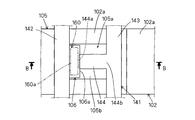
- FIG. 4 is a plan view partially showing the terminal 141 in FIG.
- FIG. 5 is a sectional view taken along line BB of the terminal 141 and the accommodating portion 105 in FIG.
- FIG. 6 is a cross-sectional view showing a modified example of FIG.
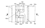
- FIG. 7 is a plan view partially showing the terminal 241.
- FIG. 8 is a cross-sectional view taken along line CC of the terminal 241 and the accommodating portion 105 in FIG.
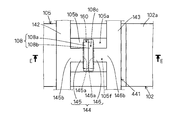
- FIG. 9 is a plan view partially showing the terminal 341.
- FIG. 10 is a cross-sectional view taken along line DD of the terminal 341 and the accommodating portion 105 in FIG.
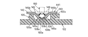
- FIG. 11 is a plan view partially showing the terminal 441.
- 12 is a cross-sectional view taken along line EE of the terminal 441 and the accommodating portion 105 in FIG.
- FIG. 13 is a plan view partially showing the terminal 541.
- 14 is a cross-sectional view taken along line FF of the terminal 541 and the accommodating portion 105 in FIG.
- FIG. 15 is a perspective view of the terminal 541 and the accommodating portion 105 in FIG.
- a vehicle door lock device (hereinafter also simply referred to as a “door lock device”) 100 according to the present embodiment includes a door outer panel (vehicle outer panel) and a door inner panel (vehicle outer panel) of a vehicle door DR. And an inner panel).
- FIG. 1 shows a vehicle door on the right side of the vehicle as a typical example of the vehicle door DR.
- the door lock device 100 includes a housing 101 that houses a door lock component of the door lock device, and a cover member 104 that is attached over the upper surface of the housing 101 and the front surface of the housing. Both the housing 101 and the cover member 104 are configured as resin members.
- the housing 101 includes a first housing structure 102 on the vehicle outer side and a second housing structure 103 on the vehicle inner side.
- a plurality of door lock components are assembled to the housing 101.
- the plurality of door lock components include a known latch mechanism 110, lock mechanism 120, double lock mechanism 130, and the like.
- the cover member 104 functions to protect the door lock components housed in the housing 101 from water and theft members entering from the outside of the vehicle door DR.
- the latch mechanism 110 generally has a function capable of holding the vehicle door DR in a closed state by engagement with a striker ST attached to the vehicle body BD.
- the lock mechanism 120 is generally configured to set the latch mechanism 110 to an unlocked state in which the engagement with the striker ST can be released or a locked state in which the engagement with the striker ST cannot be released.
- the lock mechanism 120 includes an inside open lever 121, an outside open lever 122, an open link (not shown), an active lever 123, an inside locking lever 124, an electric motor 125, and the like.
- the inside open lever 121 is configured to be rotationally driven from the initial position to the operating position in accordance with a door opening operation of an inside handle (not shown) provided inside the vehicle door DR.
- the outside open lever 122 is configured to be rotationally driven from the initial position to the operating position in accordance with a door opening operation of an outside handle (not shown) provided outside the vehicle door DR.
- the active lever 123 sets the open link in a locked state or an unlocked state by a locking operation or a locking operation of the locking / unlocking operation member.
- the inside locking lever 124 is configured to be rotationally driven between a lock position and an unlock position by a lock operation or unlock operation of a door lock knob (not shown) provided inside the vehicle door DR.
- the electric motor 125 is configured as an actuator for driving the active lever 123.
- the double lock mechanism 130 is a mechanism that can generally hold the locked state by the lock mechanism 120, and is a double lock set state that restricts the operation of the active lever 123 and a double lock unset that allows the operation of the active lever 123. It fulfills the function of selectively achieving any of the states.
- the double lock mechanism 130 includes a double lock lever 131 for locking the rotation operation of the active lever 123 and an electric motor 132 that is an actuator for driving the double lock lever 131. I have.
- the door lock device 100 having the above-described configuration includes an energization mechanism 140 in the area A of the first housing component 102 in FIG.
- the energization mechanism 140 functions to supply electricity to the electric motors 125 and 132 that are electric components.
- the electric motors 125 and 132 referred to here correspond to “electrical parts” of the present invention.
- the energizing mechanism 140 is made of a metal terminal (also referred to as a “bus bar circuit”) 141 for electrically connecting the electric motors 125 and 132 and the external terminal 200 for supplying power to the electric motor.
- 141a and a resin-made connector 150 for connecting external terminals both of the terminals 141 and 141a are plate-shaped members made of metal terminal plate pieces (thin plate pieces having a square cross section).
- the terminal 141 is assigned to the electric motor 132, and the terminal 141a is assigned to the electric motor 125.
- both the electric motors 125 and 132 and the terminals 141 and 141a are assembled to the first housing structure 102 made of resin.
- the terminal 141 here corresponds to the “terminal” of the present invention, and the first housing. "Resin housing" is constructed of the present invention by an adult 102.
- the terminal 141 extends horizontally along the mounting surface 102a of the first housing component 102, and is attached to the mounting surface 102a at the time of mounting.
- the terminal 141 includes a first terminal plate piece (also referred to as “first bus bar”) 142, a second terminal plate piece (also referred to as “second bus bar”) 143, and a connection plate.
- a piece (scheduled part) 144 is included.
- the terminal 141 is configured such that the first terminal plate piece 142 and the second terminal plate piece 143 are severably connected via the connecting plate piece 144, and is cut at the connecting plate piece 144 by a cutting tool at the time of attachment.
- a resin housing portion 105 having a housing space 105a that is recessed in the mounting surface 102a is provided at a position corresponding to the terminal 141 on the mounting surface 102a of the first housing structure 102.
- This accommodating part 105 fulfill
- FIG. This accommodating portion 105 corresponds to the “accommodating portion” of the present invention. The cutting of the connecting plate piece 144 and the bending of the cutting end portion 144a will be described. As shown in FIG. 5, the cutting tool from above to the connecting plate piece 144 of the terminal 141 downward (in the direction of the white arrow). 160 acts.
- the connecting plate piece 144 is cut through the cutting edge 160a of the cutting tool 160.
- the connecting plate piece 144 is locked from the initial position (first position) indicated by the two-dot chain line so that the cut end portion 144a is received and locked in the receiving space 105a of the receiving portion 105.
- To the second position) by the cutting edge 160a of the cutting tool 160 To the second position, by the cutting edge 160a of the cutting tool 160.
- the first terminal plate piece 142 and the second terminal plate piece 143 are electrically insulated.
- the connecting plate piece 144 in the pushed and bent state tends to return from the locking position to the initial position by being lifted by the residual stress.
- the terminal 141 may partially lift from the attachment surface 102a.
- the first terminal plate piece 142 and the second terminal plate piece 143 may come into contact with each other via the connecting plate piece 144 and short circuit. Therefore, in the terminal structure of the present embodiment, the cut end portion 144a of the connecting plate piece 144 once accommodated in the accommodating space 105a of the accommodating portion 105 connects the first terminal plate piece 142 and the second terminal plate piece 143.
- a blocking mechanism is provided to prevent returning toward the position.
- the blocking mechanism here corresponds to the “blocking mechanism” of the present invention.
- the cut end portion 144a after the cutting of the connecting plate piece 144 returns to the position where the first terminal plate piece 142 and the second terminal plate piece 143 are connected, and the first terminal plate piece 142 and the first terminal plate piece 143 are connected. It is possible to prevent the two terminal plate pieces 143 from coming into contact with each other via the connecting plate pieces 144 and short-circuiting. As a result, the electrical insulation state between the first terminal plate piece 142 and the second terminal plate piece 143 can be maintained. Further, in this case, no material waste is generated by cutting the connecting plate piece 144, and no recovery work is required. A specific embodiment relating to this blocking mechanism will be described below.
- the locking projection 106 provided on the inner bottom surface 105 b of the housing portion 105 is used as the blocking mechanism.
- the locking protrusion 106 is a sharp protrusion having a triangular cross section that protrudes from the inner bottom surface 105 b of the housing portion 105 to the protruding end 106 a that extends toward the connecting plate piece 144.
- the locking convex portion 106 is provided in a convex shape on a moving locus that passes when the cut end portion 144 a of the connecting plate piece 144 is pushed and bent in the accommodating space 105 a of the accommodating portion 105.
- this latching convex part 106 partitions the accommodation space 105a into the 1st space part (left side area
- the locking projection 106 corresponds to the “locking projection” of the present invention.
- the connecting plate piece 144 of the terminal 141 is cut by the cutting edge 160a of the cutting tool 160 at a cutting end portion 144a that is a boundary portion with the first terminal plate piece 142 (end portion on the first terminal plate piece 142 side). . Further, by lowering the cutting tool 160 linearly downward in FIG. 5, the cut connecting plate piece 144 is pushed by the cutting edge 160a of the cutting tool 160 and is turned on the second terminal plate piece 143 side. About 144b, it is pushed and bent toward the latching convex part 106, and is rotationally deformed in the first direction R1.
- the protruding end 106a of the locking convex portion 106 is disposed on the movement locus when the cutting end portion 144a of the connecting plate piece 144 rotates, and the cutting end portion 144a and the protruding end 106a interfere with each other. To do. Accordingly, when the connecting plate piece 144 in a state after cutting is rotated and deformed in the first direction R1 around the rotating end portion 144b by being pushed by the cutting edge 160a of the cutting tool 160, the cutting end portion 144a is the locking convex portion 106. The protruding end 106a is pressed.
- the locking convex portion 106 is elastically deformed by being pushed and bent by the cut end portion 144a at the protruding end 106a, thereby allowing the connecting plate piece 144 to rotate in the first direction R1. Accordingly, the cut end portion 144a of the connecting plate piece 144 overcomes the protruding end 106a by bending the protruding end 106a of the locking convex portion 106 from the first space portion side, and becomes the protruding end 106a in the second space portion. It is set to the locking position to be locked.
- the cut end portion 144a of the connecting plate piece 144 is locked in contact with the protruding end 106a of the locking convex portion 106 by the residual stress after bending deformation, and thus the second direction opposite to the first direction R1.
- R2 the rotation deformation of R2 being prevented, an operation of detaching from the locking position and returning to the initial position intervenes on the movement locus between the locking position of the cutting end 144a and the initial position. It is blocked by the stop projection 106.
- the connecting plate piece 144 is held in the locking position by utilizing the engagement relationship between the protruding portions 106a of the connecting plate piece 144 and the protruding end 106a of the locking protruding portion 106. It is a form to do.
- the cutting operation is simplified because the cutting end 144a is locked to the locking projection 106 positioned on the movement locus in accordance with the pushing and bending operation of the cutting end 144a of the connecting plate piece 144.
- the blocking mechanism can be simplified by using the locking projection 106 provided on the inner bottom surface 105 b of the housing portion 105.
- the cutting end portion 144a of the connecting plate piece 144 can be smoothly guided to the locking position locked by the protruding end 106a of the locking projection 106 by utilizing the bending deformation operation.
- the first space portion of the accommodation space 105a can be used as a pushing space for pushing the cut end portion 144a formed after cutting the connecting plate piece 144 into the second space portion as it is.
- the locking projection 106 includes an inclined surface 106 b that is inclined with respect to the inner bottom surface 105 b of the housing portion 105.
- the inclined surface 106b is preferably configured to be inclined so that the distance from the inner wall surface 105c of the accommodating portion 105 is gradually expanded upward.
- the first space portion of the accommodation space 105 a is a concave space portion that is defined by the inclined surface 106 b of the locking projection 106 and the inner wall surface 105 c of the accommodation portion 105 in the accommodation space 105 a of the accommodation portion 105. 106c. Therefore, the sharp cutting edge 160a of the cutting tool 160 after cutting the connecting plate piece 144 can be temporarily accommodated in the space 106c.
- the cutting edge 160a used for cutting is continuously accommodated in the space 106c.
- the cutting end portion 144a is pushed into the second space portion from the first space portion as it is, and a series of operations of the cutting tool 160 can be smoothly performed only by one pressing operation. it can.
- a locking projection 107 as shown in FIG. 6 can be used instead of the locking projection 106 having the above-described configuration.
- the locking projection 107 corresponds to the “locking projection” of the present invention. While the locking convex portion 106 is provided on the inner bottom surface 105 b of the housing portion 105, the locking convex portion 107 is provided on the inner wall surface 105 c of the housing portion 105. In this case, the protruding end 107a of the locking convex portion 107 is disposed on the movement locus when the cut end portion 144a of the connecting plate piece 144 rotates.
- the locking projection 107 divides the accommodation space 105a into a first space (upper region in FIG. 6) and a second space (lower region in FIG. 5).
- this locking projection 107 is used, similarly to the case where the locking projection 106 is used, the connecting plate piece 144 of the terminal 141 is cut by the cutting edge 160a of the cutting tool 160 at the cutting end 144a. Thereafter, the locking convex portion 107 obstructs the pushing / bending operation of the cutting tool 160. Therefore, the cut connecting plate piece 144 is pushed in by a tool different from the cutting tool 160, and the rotation end portion 144b is the center. It turns and deforms in the first direction R1.
- the cutting end portion 144a of the connecting plate piece 144 gets over the protruding end 107a by bending and deforming the protruding end 107a of the locking convex portion 107 from the first space portion side, and the protruding end 107a in the second space portion. It is set to a locking position to be locked to.
- the connecting plate piece 144 since the connecting plate piece 144 is prevented from rotating in the second direction R2 by the protruding end 107a of the locking projection 107, the movement of the connecting plate piece 144 to return to the initial position by moving from the locking position is the cutting end. It is blocked by the locking projection 107 interposed on the movement locus between the locking position of the portion 144a and the initial position.
- the cutting operation is simplified because the cutting end 144a is locked to the locking projection 107 located on the movement locus in accordance with the pushing and bending operation of the cutting end 144a of the connecting plate piece 144.
- the blocking mechanism can be simplified by using the locking projection 107 provided on the inner wall surface 105 c of the housing portion 105. The operation until the connecting plate piece 144 is locked at the locking position is performed in two stages: a cutting operation of the connecting plate piece 144 by the cutting tool 160 and a push-bending operation by another tool. .
- the blocking mechanism is configured by using the locking projections 106 and 107 of the housing portion 105, whereas in the second embodiment, the inner wall surface 105d of the housing portion 105 is formed. , 105e is used to constitute the blocking mechanism.
- the connecting plate piece 144 includes a pair of sharpened locking claws 144 c and 144 d that protrude on both sides in the plate width direction (vertical direction in FIG. 7).
- the locking claws 144c and 144d correspond to the “locking claws” of the present invention.
- the connecting plate piece 144 has a length between the front end of one locking claw 144c and the front end of the other locking claw 144d between the inner wall surfaces 105d and 105e facing each other in the housing portion 105. It is configured to slightly exceed d1.
- the connecting plate piece 144 is prevented from rotating in the second direction R2 by the engagement between the pair of locking claws 144c and 144d and the inner wall surfaces 105d and 105e of the accommodating portion 105, so The action of coming off and returning to the initial position is prevented.
- the connecting plate piece 144 uses the engagement relationship between the convex portions and the concave portions formed by the pair of locking claws 144c and 144d of the connecting plate piece 144 and the inner wall surfaces 105d and 105e of the accommodating portion 105. Is held in the locking position.
- the blocking mechanism can be simplified by using the inner wall surfaces 105d and 105e of the housing portion 105 itself.
- the cut end portion 144a of the connecting plate piece 144 can be firmly locked via the pair of locking claws 144c and 144d. If necessary, the pair of locking claws 144c and 144d may be omitted, and a structure in which the side surface of the connecting plate piece 144 is directly hooked on the inner wall surfaces 105d and 105e of the housing portion 105 may be employed.
- the blocking mechanism is configured by using a locking groove 105 f provided on the inner bottom surface 105 b of the housing portion 105.
- the locking groove 105f extends along the longitudinal direction of the connecting plate piece 144 of the terminal 341, and has a groove width slightly smaller than the plate width d2 of the connecting plate piece 144.
- the locking groove 105f is formed in a concave shape on a movement trajectory that passes when the cut end portion 144a of the connecting plate piece 144 in the inner bottom surface 105b of the accommodating portion 105 is pushed and bent in the accommodating space 105a.
- the locking groove 105f corresponds to the “locking groove” of the present invention.
- the third embodiment is a form in which the connecting plate piece 144 is held at the locking position by utilizing the engagement relationship between the convex portion and the concave portion by the connecting plate piece 144 and the locking groove 105f.
- the cutting operation is simplified because the cutting end 144a is locked to the locking groove 105f located on the movement locus in accordance with the pushing and bending operation of the cutting end 144a of the connecting plate piece 144.
- the blocking mechanism can be simplified by using the locking groove 105f provided in the inner bottom surface 105b of the housing portion 105.
- the connecting plate piece 144 can be provided with a shape such as the pair of locking claws 144c and 144d. In this case, the connecting plate piece 144 is more firmly locked at the locking position by being hooked on the groove wall surface of the locking groove 105f by the pair of locking claws 144c and 144d.
- the end portion on the first terminal plate piece 142 side after cutting and the end portion on the second terminal plate piece 143 side on the opposite side can be made as long as possible.
- the end portion on the first terminal plate piece 142 side after cutting can be as far as possible from the cutting position.
- it can replace with the form which cut
- the connecting plate piece 144 is cut at the end portion on the first terminal plate piece 142 side, whereas in the fourth embodiment, as shown in FIG.
- the connecting plate piece 144 of the terminal 441 is cut in an intermediate region between the end portion on the first terminal plate piece 142 side and the end portion on the second terminal plate piece 143 side.
- the connecting plate piece 144 is divided into a first plate piece portion 145 on the first terminal plate piece 142 side and a second plate piece portion 146 on the second terminal plate piece 143 side.
- the locking convex portion 108 provided on the inner bottom surface 105b of the accommodating portion 105 is used as the blocking mechanism.
- the locking projection 108 includes a projection 108 a assigned to the first plate piece 145 and a projection 108 b assigned to the second plate piece 146.
- These protrusions 108a and 108b are both sharply-pointed protrusions having a triangular cross section, and perform the same function as the locking protrusion 106 described above. That is, the first plate piece portion 145 after being cut by the cutting edge 160a of the cutting tool 160 is continuously rotated and bent by the cutting edge 160a of the cutting tool 160 by the rotating end portion 145b which is the end portion on the first terminal plate piece 142 side. 12 is rotated and deformed in the direction of the arrow in FIG.
- the second plate piece portion 146 after being cut by the cutting edge 160a of the cutting tool 160 is a rotating end portion that is the end portion on the second terminal plate piece 143 side by subsequent bending by the cutting edge 160a of the cutting tool 160. Rotating and deforming in the direction of the arrow in FIG.
- the cut end portions 145a and 146a are set at a locking position where the cutting pieces 145a and 146a get over the tips of the projections 108a and 108b and are locked by the tips.
- each of the plate pieces 145 and 146 is prevented from moving out of the locking position and returning to the initial position by the protrusions 108a and 108b of the locking projection 108.
- the space portion 108c formed by the protrusion 108a and the protrusion 108b of the locking projection 108 facing each other is a plate piece portion 145, like the space portion 106c of the locking projection 106.
- the cutting edge 160a of the cutting tool 160 after the 146 is pushed in can be accommodated. Therefore, the cutting tool 160 is accommodated in the space portion 108c in a series of operations (cutting and bending operations) from cutting the connecting plate piece 144 to pressing and bending each of the first plate piece portion 145 and the second plate piece portion 146. It is possible to carry out by only one push-down operation until the end.
- the connecting plate piece 144 of the terminal 541 is cut in the intermediate region between the first terminal plate piece 142 and the second terminal plate piece 143 in the fourth embodiment. It is the same as the form.
- the blocking mechanism is configured by using a locking groove 105f formed by further denting a part of the inner bottom surface 105b of the housing portion 105 into a groove shape. .
- the locking groove 105f extends along the longitudinal direction of the connecting plate piece 144 of the terminal 541, and has a groove width slightly smaller than the plate width d2 of the connecting plate piece 144.
- both the first plate piece portion 145 and the second plate piece portion 146 after cutting are pushed and bent by the cutting edge 160a of the cutting tool 160 in the direction of the arrow in FIG.
- both the first plate piece 145 (cut end 145a) and the second plate piece 146 (cut end 146a) made of metal are pushed into the locking groove 105f of the resin containing portion 105 to form the groove.
- both the 1st board piece part 145 and the 2nd board piece part 146 are prevented from the operation
- each cut piece can be provided with a shape such as the pair of locking claws 144c and 144d. In this case, each cut piece is more firmly locked at the locking position by being caught by the pair of locking claws 144c and 144d on the groove wall surface of the locking groove 105f.
- space portions 109 formed by further denting a part of the inner bottom surface 105b of the accommodating portion 105 into a V shape.
- This space portion 109 can accommodate the cutting edge 160a of the cutting tool 160 after the plate pieces 145 and 146 have been pushed in, like the space portions 106c and 108c. Therefore, the cutting tool 160 is accommodated in the space portion 109 through a series of operations (cutting and bending operations) from cutting the connecting plate piece 144 to pushing and bending each of the first plate piece portion 145 and the second plate piece portion 146. It is possible to carry out by only one push-down operation until the end.
- the cutting edge 160a of the cutting tool 160 interferes with the accommodating portion 105 because it is only necessary to cut an intermediate region of the connecting plate piece 144 that is separated from the opening edge of the accommodating portion 105.
- the cutting operation by the cutting tool 160 can be performed without worrying about doing.
- the present invention is not limited to the above exemplary embodiment, and various applications and modifications are possible.
- each of the following embodiments to which the above embodiment is applied can be implemented.
- the shape of the locking projection is not limited to the sharp shape.
- Various convex shapes such as a flat plate shape and a hook shape can be employed.
- the cutting end 144a is positioned on the movement trajectory along with the pushing and bending operation of the cutting end 144a of the connecting plate piece 144 (the locking projections 106, 107,
- the locking portion can be provided at a position deviating from the movement trajectory of the cutting end portion 144a.
- the cutting end portion 144a of the connecting plate piece 144 can be set to the locking position by the locking portion by manual operation.
- the terminal structure for the terminal 141 for electrically connecting the electric motor 132 and the external terminal 200 has been described.
- the present invention can also be applied to a terminal structure for a terminal assigned to other electrical components.
- the essential structure of the door lock device 100 described above can be applied to each vehicle door of the vehicle.
- the essential structure of the door lock device 100 of the present invention is applied to the left and right doors for the front seat of the vehicle, the left and right doors for the rear seat of the vehicle, and the door (back door) at the rear of the vehicle. Can do.
Landscapes
- Engineering & Computer Science (AREA)
- Mechanical Engineering (AREA)
- Lock And Its Accessories (AREA)
Abstract
車両用ドアロック装置のターミナル構造において、金属製のターミナルの切断によって形成された複数のターミナル板片の電気的な絶縁状態を維持するのに有効な技術を提供する。本発明にかかる車両用ドアロック装置のターミナル構造は、第1ターミナル板片及び第2ターミナル板片が連結板片を介して切断可能に連結されてなる金属製のターミナルと、ターミナルのうち切断後に押し曲げられた連結板片の切断端部を収容するために凹み形成された収容空間を有する樹脂製の収容部と、収容部の収容空間に収容された連結板片の切断端部が第1ターミナル板片と第2ターミナル板片とを連結する位置に向けて戻るのを阻止する阻止機構と、を備える。
Description
本発明は、車両ドアに組付けられる車両用ドアロック装置に含まれる電気部品を外部端子に電気的に接続するためのターミナル構造に関する。
特許文献1には、この種の車両用ドアロック装置のターミナル構造の一例が開示されている。このターミナル構造では、電気モータやマイクロスイッチのような電気部品と外部端子(給電用の端子や通信用の端子)とを電気的に接続する金属製のターミナル(バスバー回路)が用いられている。このターミナルは、導電性の金属板の打ち抜き加工によって形成されており、連結板片(タイバー)を介して一体状に繋がった2つのターミナル板片(バスバー)を備えている。このターミナルは、ハウジングへの取付け時に連結板片が切断ツールによって切断されることで2つのターミナル板片に分断される。この場合、一方のターミナル板片に連接している連結板片は、切断後に切断ツールによって押し曲げられて、ハウジングに設けられている凹状の受容部に収容される。これにより、ターミナル板片同士が電気的に絶縁される。
(発明が解決しようとする課題)
上記のターミナル構造によれば、ターミナル板片同士を電気的に絶縁するためにターミナルの連結板片が切断ツールによって切断されても、材料屑が発生することがなく、その回収作業も必要ないという作用効果が得られる。一方で、切断ツールの押し付けによって曲げ変形した状態の連結板片は、曲げ変形後の残留応力によって浮き上がることにより切断前の位置に戻ろうとする。その結果、ターミナル板片同士が連結板片を介して接触して短絡するおそれがある。
そこで本発明は、上記の点に鑑みてなされたものであり、その目的の1つは、車両用ドアロック装置のターミナル構造において、金属製のターミナルの切断によって形成された複数のターミナル板片の電気的な絶縁状態を維持するのに有効な技術を提供することである。
(課題を解決するための手段)
上記目的を達成するため、本発明に係る車両用ドアロック装置のターミナル構造は、金属製のターミナルと、樹脂製の収容部と、阻止機構と、を備える。金属製のターミナルは、車両用ドアロック装置の樹脂製ハウジングに設けられた取付け面に被着され、車両用ドアロック装置に含まれる電気部品とこの電気部品へ給電するための外部端子とをそれぞれ接続する第1ターミナル板片及び第2ターミナル板片が連結板片を介して切断可能に連結されることによって構成される。樹脂製の収容部は、ターミナルのうち切断後に押し曲げられた連結板片の切断端部を収容するために取付け面に凹み形成された収容空間を有する。
上記目的を達成するため、本発明に係る車両用ドアロック装置のターミナル構造は、金属製のターミナルと、樹脂製の収容部と、阻止機構と、を備える。金属製のターミナルは、車両用ドアロック装置の樹脂製ハウジングに設けられた取付け面に被着され、車両用ドアロック装置に含まれる電気部品とこの電気部品へ給電するための外部端子とをそれぞれ接続する第1ターミナル板片及び第2ターミナル板片が連結板片を介して切断可能に連結されることによって構成される。樹脂製の収容部は、ターミナルのうち切断後に押し曲げられた連結板片の切断端部を収容するために取付け面に凹み形成された収容空間を有する。
阻止機構は、収容部の収容空間に収容された連結板片の切断端部が第1ターミナル板片と第2ターミナル板片とを連結する位置に向けて戻るのを阻止する機能を果たす。これにより、連結板片の切断後の切断端部が第1ターミナル板片と第2ターミナル板片とを連結する位置に戻って、第1ターミナル板片と第2ターミナル板片が連結板片を介して互いに接触して短絡するのを防止できる。その結果、第1ターミナル板片と第2ターミナル板片との電気的な絶縁状態を維持することができる。また、この場合、連結板片の切断によって材料屑が発生することがなく、その回収作業も必要ない。
上記のターミナル構造では、阻止機構は、収容部の収容空間のうち連結板片の切断端部が押し曲げられる際に通る移動軌跡上に凸状に設けられ、連結板片の切断端部を係止可能な係止凸部によって構成されるのが好ましい。この場合、連結板片の切断端部の押し曲げ動作に伴って当該切断端部がその移動軌跡上に位置する係止凸部に係止されるため係止操作が簡単になる。また、収容部の内底面や内壁面に設けた係止凸部を利用することによって阻止機構の簡素化を図ることができる。
上記のターミナル構造では、係止凸部は、収容部の内底面又は内壁面から連結板片に向けて先鋭状に突出し、且つ収容空間を第1空間部と第2空間部とに区画するのが好ましい。また、連結板片の切断端部は、係止凸部に向けて押し曲げられる際に第1空間部側から係止凸部の突出端を曲げ変形させることによって突出端を乗り越えて第2空間部において突出端に係止されるのが好ましい。この場合、連結板片の切断端部は、曲げ変形後の残留応力によって係止凸部の突出端に当接して係止される。これにより、連結板片の切断端部を、その曲げ変形動作を利用して、係止凸部の突出端によって係止される係止位置まで円滑に誘導することができる。また、収容空間の第1空間部を連結板片の切断後に形成される切断端部をそのまま第2空間部に押し込むための押し込み空間として利用することができる。
上記のターミナル構造では、阻止機構は収容部によって構成されるのが好ましい。この場合、収容部は、連結板片の切断端部が収容空間において押し曲げられる際に当該切断端部を内壁面との面接触によって係止可能な部位である。この場合、収容部自体の内壁面を利用することで阻止機構の簡素化を図ることができる。
上記のターミナル構造では、阻止機構は係止溝によって構成されるのが好ましい。この場合、係止溝は、収容部の内底面のうち連結板片の切断端部が収容空間において押し曲げられる際に通る移動軌跡上に凹み形成され、連結板片の切断端部を溝壁面との面接触によって係止可能な溝である。この場合、連結板片の切断端部の押し曲げ動作に伴って当該切断端部がその移動軌跡上に位置する係止溝に係止されるため係止操作が簡単になる。また、収容部の内底面に設けた係止溝を利用することで阻止機構の簡素化を図ることができる。
上記のターミナル構造では、阻止機構は、連結板片にその板幅方向に延出するように設けられ収容部の内壁面或いは係止溝の溝壁面に引っ掛かる先鋭状の係止爪を含むのが好ましい。これにより、連結板片の切断端部を係止爪を介して強固に係止することができる。
上記のターミナル構造では、係止凸部は、収容部の内底面から連結板片に向けて先鋭状に突出し、収容空間の第1空間部は、収容部の内壁面と係止凸部のうち収容部の内底面に対して傾斜した傾斜面とによって区画されているのが好ましい。これによれば、切断ツールを使用して連結板片を切断した後にそのまま切断端部を第1空間部から第2空間部に押し込む、切断ツールの一連の動作を1回の押し下げ操作のみによって円滑に行うことができる。
上記のターミナル構造では、連結板片は、第1ターミナル板片側端部と第2ターミナル板片側端部のいずれか一方にて切断された後、押し曲げによって当該ターミナル板片側端部とは反対側の端部を中心に回動変形して収容部の収容空間に収容されるのが好ましい。これによれば、連結板片の全長のうち切断後のターミナル板片側端部とその反対側の端部との間の長さをできるだけ長くするこができる。その結果、切断後のターミナル板片側端部を切断位置からできるだけ遠ざけることができる。
上記のターミナル構造では、連結板片は、第1ターミナル板片側端部と第2ターミナル板片側端部との間の中間領域にて切断されて第1ターミナル板片側の第1板片部と第2ターミナル板片側の第2板片部とに分断された後、第1板片部が押し曲げによって第1ターミナル板片側端部を中心に回動変形して収容部の収容空間に収容され、且つ第2板片部が押し曲げによって第2ターミナル板片側端部を中心に回動変形して収容部の収容空間に収容されるのが好ましい。これによれば、連結板片のうち収容部の開口縁から離間した中間領域を切断すればよいため、切断ツールの刃先が収容部に干渉することを気にすることなく切断ツールによる切断操作を行うことができる。
以上のように、本発明によれば、車両用ドアロック装置のターミナル構造において、金属製のターミナルの切断によって形成された複数のターミナル板片の電気的な絶縁状態を維持することが可能になった。
以下、本発明の実施形態を図面を参照しながら説明する。なお、当該図面では、車両前方及び車両後方をそれぞれ矢印X1及び矢印X2で示し、車両上方及び車両下方をそれぞれ矢印Y1及び矢印Y2で示している。車両ドアに組付けられる前の状態の車両用ドアロック装置に対して、また車両ドアに組付けられた後の状態の車両用ドアロック装置に対して、これらの方向を適用することができる。
図1に示されるように、本実施の形態の車両用ドアロック装置(以下、単に「ドアロック装置」ともいう)100は、車両ドアDRのドアアウタパネル(車外側パネル)とドアインナパネル(車内側パネル)とによって区画される領域に組付けられる。図1にはこの車両ドアDRの典型例として車両右側の車両ドアが記載されている。
ドアロック装置100は、当該ドアロック装置のドアロック構成要素を収容するハウジング101と、このハウジング101のハウジング上面及びハウジング前面にわたって取付けられたカバー部材104と、を備えている。ハウジング101及びカバー部材104はいずれも樹脂製の部材として構成されている。
ハウジング101は、車外側の第1ハウジング構成体102と、車内側の第2ハウジング構成体103とによって構成されている。このハウジング101に複数のドアロック構成要素が組付けられている。この複数のドアロック構成要素には、周知のラッチ機構110、ロック機構120及びダブルロック機構130等が含まれる。カバー部材104は、車両ドアDRの外部から侵入した水や盗難用部材からハウジング101に収容されたドアロック構成要素を保護する機能を果たす。
ラッチ機構110は、概して車体BDに取付けられたストライカSTとの係合によって車両ドアDRを閉止状態に保持可能な機能を有する。ロック機構120は、概してラッチ機構110をストライカSTとの係合が解除可能なアンロック状態、或いはストライカSTとの係合が解除不能なロック状態に設定するように構成される。このロック機構120は、図2に示されるように、インサイドオープンレバー121、アウトサイドオープンレバー122、オープンリンク(図示省略)、アクティブレバー123、インサイドロッキングレバー124及び電気モータ125等を備えている。
インサイドオープンレバー121は、車両ドアDRの内側に設けられたインサイドハンドル(図示省略)のドア開放操作に伴って、初期位置から作動位置へと回転駆動されるように構成されている。アウトサイドオープンレバー122は、車両ドアDRの外側に設けられたアウトサイドハンドル(図示省略)のドア開放操作に伴って、初期位置から作動位置へと回転駆動されるように構成されている。アクティブレバー123は、施解錠操作部材のロック操作或いはロック操作によってオープンリンクをロック状態或いはアンロック状態に設定する。インサイドロッキングレバー124は、車両ドアDRの内側に設けられたドアロックノブ(図示省略)のロック操作或いはロック解除操作によってロック位置とアンロック位置との間で回転駆動されるように構成されている。電気モータ125は、アクティブレバー123を駆動するためのアクチュエータとして構成される。
ダブルロック機構130は、概してロック機構120によるロック状態を保持することが可能な機構であり、アクティブレバー123の作動を規制するダブルロックセット状態と、アクティブレバー123の作動を許容するダブルロックアンセット状態とのいずれかの状態を選択的に達成する機能を果たす。このダブルロック機構130は、図2に示されるように、アクティブレバー123の回転動作をロックするためのダブルロックレバー131と、ダブルロックレバー131を駆動するためのアクチュエータである電気モータ132と、を備えている。
尚、上記のラッチ機構110、ロック機構120及びダブルロック機構130のそれぞれの更なる具体的な構成については、例えば特開2002-38799号公報に開示の「被係止機構」、「第1作動機構」及び「第2作動機構」等が参照される。
上記構成のドアロック装置100は、図2中の第1ハウジング構成体102のA領域に通電機構140を備えている。この通電機構140は、電気部品である電気モータ125,132に電気を供給する機能を果たす。ここでいう電気モータ125,132が本発明の「電気部品」に相当する。
この目的のために、通電機構140は、電気モータ125,132と当該電気モータへの給電用の外部端子200とを電気的に接続するための金属製のターミナル(「バスバー回路ともいう)141,141aと、外部端子接続用の樹脂製のコネクタ150とを、備えている。ターミナル141,141aはともに金属製のターミナル板片(断面が四角形の薄板片)によって構成された板状部材である。ターミナル141が電気モータ132に割り当てられ、ターミナル141aが電気モータ125に割り当てられている。この場合、電気モータ125,132及びターミナル141,141aの双方が樹脂製の第1ハウジング構成体102に組付けられる。ここでいうターミナル141が本発明の「ターミナル」に相当し、第1ハウジング構成体102によって本発明の「樹脂製ハウジング」が構成される。
図3に示されるように、ターミナル141は、第1ハウジング構成体102の取付け面102aに沿って水平状に延在しており、且つ取付け時に取付け面102aに被着される。図3及び図4が参照されるように、ターミナル141は、第1ターミナル板片(「第1バスバー」ともいう)142、第2ターミナル板片(「第2バスバー」ともいう)143及び連結板片(切断予定部)144を含む。このターミナル141は、第1ターミナル板片142及び第2ターミナル板片143が連結板片144を介して切断可能に連結されてなり、取付け時に切断ツールによって連結板片144において切断される。
第1ハウジング構成体102の取付け面102aのうちターミナル141に対応する位置には、取付け面102aに凹み形成された収容空間105aを有する樹脂製の収容部105が設けられている。この収容部105は、ターミナル141のうち切断後に押し曲げられた連結板片144の切断端部144aを収容する機能を果たす。この収容部105が本発明の「収容部」に相当する。連結板片144の切断及び切断端部144aの押し曲げについて説明すると、図5に示されるように、ターミナル141の連結板片144に対して上方から図中下向き(白抜き矢印方向)に切断ツール160が作用する。これにより、切断ツール160の刃先160aを介して連結板片144が切断される。切断後の連結板片144は、切断端部144aが収容部105の収容空間105aに収容されて係止されるように、二点鎖線で示される初期位置(第1位置)から係止位置(第2位置)へと切断ツール160の刃先160aによって押し曲げられる。この場合、連結板片144が曲げ変形(塑性変形)する結果、第1ターミナル板片142及び第2ターミナル板片143が電気的に絶縁される。
ところで、押し曲げられた状態の連結板片144は、その残留応力によって浮き上がることにより係止位置から初期位置に戻ろうとする。特に、ターミナル141に取付け時の荷重が作用すると、取付け面102aから部分的に浮き上がる場合がある。このような場合、連結板片144が初期位置まで戻ると、第1ターミナル板片142及び第2ターミナル板片143が連結板片144を介して接触して短絡するおそれがある。そこで、本実施の形態のターミナル構造は、収容部105の収容空間105aに一旦収容された連結板片144の切断端部144aが第1ターミナル板片142と第2ターミナル板片143とを連結する位置に向けて戻るのを阻止するための阻止機構を備えている。ここでいう阻止機構が本発明の「阻止機構」に相当する。
この阻止機構によれば、連結板片144の切断後の切断端部144aが第1ターミナル板片142と第2ターミナル板片143とを連結する位置に戻って、第1ターミナル板片142と第2ターミナル板片143が連結板片144を介して互いに接触して短絡するのを防止できる。その結果、第1ターミナル板片142と第2ターミナル板片143との電気的な絶縁状態を維持することができる。また、この場合、連結板片144の切断によって材料屑が発生することがなく、その回収作業も必要ない。この阻止機構に関する具体的な実施形態について以下に説明する。
(第1の実施形態)
図4及び図5に示される第1の実施形態では、前記の阻止機構として収容部105の内底面105bに設けられた係止凸部106が用いられている。この係止凸部106は、収容部105の内底面105bから連結板片144に向かう突出端106aまで突出する三角形断面の先鋭状の突起である。この係止凸部106は、収容部105の収容空間105aのうち連結板片144の切断端部144aが押し曲げられる際に通る移動軌跡上に凸状に設けられている。また、この係止凸部106は、収容空間105aを第1空間部(図5中の左側領域)と第2空間部(図5中の右側領域)とに区画する。この係止凸部106が本発明の「係止凸部」に相当する。
図4及び図5に示される第1の実施形態では、前記の阻止機構として収容部105の内底面105bに設けられた係止凸部106が用いられている。この係止凸部106は、収容部105の内底面105bから連結板片144に向かう突出端106aまで突出する三角形断面の先鋭状の突起である。この係止凸部106は、収容部105の収容空間105aのうち連結板片144の切断端部144aが押し曲げられる際に通る移動軌跡上に凸状に設けられている。また、この係止凸部106は、収容空間105aを第1空間部(図5中の左側領域)と第2空間部(図5中の右側領域)とに区画する。この係止凸部106が本発明の「係止凸部」に相当する。
一方で、ターミナル141の連結板片144は、第1ターミナル板片142との境界部分(第1ターミナル板片142側端部)である切断端部144aにおいて切断ツール160の刃先160aによって切断される。更に、切断ツール160を図5中の下向きに直線的に下降させることによって、切断後の連結板片144は切断ツール160の刃先160aによって押し込まれて第2ターミナル板片143側の回動端部144bを中心に係止凸部106に向けて押し曲げられて第1方向R1に回動変形する。この場合、連結板片144の切断端部144aが回動する際の移動軌跡上に係止凸部106の突出端106aが配置されており、且つ切断端部144aと突出端106aとが互いに干渉する。従って、切断後の状態の連結板片144が切断ツール160の刃先160aによる押し込みによって回動端部144bを中心に第1方向R1に回動変形する際、切断端部144aが係止凸部106の突出端106aを押圧する。
このとき、係止凸部106は、その突出端106aにおいて切断端部144aによって押し曲げられて弾性変形することで連結板片144の第1方向R1の回動変形を許容する。従って、連結板片144の切断端部144aは、第1空間部側から係止凸部106の突出端106aを曲げ変形させることによって突出端106aを乗り越えて第2空間部において当該突出端106aに係止される係止位置に設定される。この場合、連結板片144の切断端部144aは、曲げ変形後の残留応力によって係止凸部106の突出端106aに当接して係止されるため、第1方向R1と反対の第2方向R2の回動変形が阻止される結果、係止位置から外れて初期位置に向けて戻ろうとする動作が、切断端部144aの係止位置と初期位置との間の移動軌跡上に介在する係止凸部106によって阻止される。
要するに、第1の実施形態は、連結板片144の切断端部144aと係止凸部106の突出端106aによる凸部同士の係合関係を利用して連結板片144を係止位置に保持する形態である。この場合、連結板片144の切断端部144aの押し曲げ動作に伴って当該切断端部144aがその移動軌跡上に位置する係止凸部106に係止されるため係止操作が簡単になる。また、収容部105の内底面105bに設けた係止凸部106を利用することによって阻止機構の簡素化を図ることができる。また、連結板片144の切断端部144aを、その曲げ変形動作を利用して、係止凸部106の突出端106aによって係止される係止位置まで円滑に誘導することができる。また、収容空間105aの第1空間部を連結板片144の切断後に形成される切断端部144aをそのまま第2空間部に押し込むための押し込み空間として利用することができる。
尚、係止凸部106は、収容部105の内底面105bに対して傾斜した傾斜面106bを備えている。この傾斜面106bは、収容部105の内壁面105cとの間隔が上方に向かうにつれて徐々に拡張されるように傾斜した構成であるのが好ましい。この場合、収容空間105aの第1空間部は、収容部105の収容空間105aのうちこの係止凸部106の傾斜面106bと収容部105の内壁面105cとによって区画形成される凹状の空間部106cとして構成される。従って、連結板片144を切断した後の切断ツール160の先鋭状の刃先160aを空間部106cに一時的に収容することが可能になる。その結果、連結板片144を切断ツール160の刃先160aによる押し付けによって切断しつつ係止位置まで押し曲げる際、切断に使用された刃先160aが引き続いて空間部106cに収容されるため、切断ツール160を使用して連結板片144を切断した後にそのまま切断端部144aを第1空間部から第2空間部に押し込む、切断ツール160の一連の動作を1回の押し下げ操作のみによって円滑に行うことができる。
上記構成の係止凸部106に代えて図6に示されるような係止凸部107を用いることもできる。この係止凸部107が本発明の「係止凸部」に相当する。係止凸部106が収容部105の内底面105bに設けられていたのに対して、この係止凸部107は収容部105の内壁面105cに設けられている。この場合、連結板片144の切断端部144aが回動する際の移動軌跡上に係止凸部107の突出端107aが配置されている。この係止凸部107は、収容空間105aを第1空間部(図6中の上側領域)と第2空間部(図5中の下側領域)とに区画する。この係止凸部107を用いる場合も、係止凸部106を用いる場合と同様に、ターミナル141の連結板片144は、切断端部144aにおいて切断ツール160の刃先160aによって切断される。その後、係止凸部107は切断ツール160の押し曲げ操作の邪魔になるため、切断後の連結板片144は、切断ツール160とは別のツールによって押し込まれ、回動端部144bを中心に第1方向R1に回動変形する。
このとき、連結板片144の切断端部144aは、第1空間部側から係止凸部107の突出端107aを曲げ変形させることによって突出端107aを乗り越えて第2空間部において当該突出端107aに係止される係止位置に設定される。このとき、連結板片144は、係止凸部107の突出端107aによって第2方向R2の回動変形が阻止されるため、係止位置から外れて初期位置に戻ろうとする動作が、切断端部144aの係止位置と初期位置との間の移動軌跡上に介在する係止凸部107によって阻止される。この場合、連結板片144の切断端部144aの押し曲げ動作に伴って当該切断端部144aがその移動軌跡上に位置する係止凸部107に係止されるため係止操作が簡単になる。また、収容部105の内壁面105cに設けた係止凸部107を利用することによって阻止機構の簡素化を図ることができる。尚、連結板片144が係止位置にて係止されるまでの操作は、切断ツール160による連結板片144の切断操作と別のツールによる押し曲げ操作の二段階で実行されることになる。
(第2の実施形態)
前述の第1の実施形態では、収容部105の係止凸部106,107を利用して前記の阻止機構を構成したのに対して、第2の実施形態では、収容部105の内壁面105d,105eを利用して前記の阻止機構を構成している。図7に示されるように、連結板片144は、その板幅方向(図7中の上下方向)の両側に突出する先鋭状の一対の係止爪144c,144dを備えている。この係止爪144c,144dが本発明の「係止爪」に相当する。また、この連結板片144は、一方の係止爪144cの先端と他方の係止爪144dの先端との間の長さが、収容部105のうち互いに対向する内壁面105d,105e間の間隔d1を若干上回るように構成されている。
前述の第1の実施形態では、収容部105の係止凸部106,107を利用して前記の阻止機構を構成したのに対して、第2の実施形態では、収容部105の内壁面105d,105eを利用して前記の阻止機構を構成している。図7に示されるように、連結板片144は、その板幅方向(図7中の上下方向)の両側に突出する先鋭状の一対の係止爪144c,144dを備えている。この係止爪144c,144dが本発明の「係止爪」に相当する。また、この連結板片144は、一方の係止爪144cの先端と他方の係止爪144dの先端との間の長さが、収容部105のうち互いに対向する内壁面105d,105e間の間隔d1を若干上回るように構成されている。
このため、図8に示されるように、切断後の連結板片144は、切断ツール160の刃先160aによって収容空間105aにおいて第1方向R1に押し曲げられる際に、金属製の一対の係止爪144c,144dが樹脂製の内壁面105d,105eに面接触する(一対の係止爪144c,144dが内壁面105d,105eに引っ掛かる)ことによって係止位置に係止される(保持される)。特に、金属製の一対の係止爪144c,144dがそれぞれ樹脂製の収容部105の内壁面105d,105eに引っ掛かることによって係止位置に係止される(保持される)。この場合、連結板片144は、一対の係止爪144c,144dと収容部105の内壁面105d,105eとの係合によって第2方向R2の回動変形が阻止されるため、係止位置から外れて初期位置に戻ろうとする動作が阻止される。
要するに、第2の実施形態は、連結板片144の一対の係止爪144c,144dと収容部105の内壁面105d,105eによる凸部と凹部との係合関係を利用して連結板片144を係止位置に保持する形態である。この場合、収容部105自体の内壁面105d,105eを利用することで阻止機構の簡素化を図ることができる。特に、連結板片144の切断端部144aを一対の係止爪144c,144dを介して強固に係止することができる。尚、必要に応じては一対の係止爪144c,144dを省略し、連結板片144の側面が収容部105の内壁面105d,105eに直に引っ掛かる構造を採用することもできる。
(第3の実施形態)
第3の実施形態では、図9に示されるように、収容部105の内底面105bに設けられた係止溝105fを利用して前記の阻止機構を構成している。係止溝105fは、ターミナル341の連結板片144の長手方向に沿って延在しており、且つ連結板片144の板幅d2を若干下回る溝幅を備えている。この係止溝105fは、収容部105の内底面105bのうち連結板片144の切断端部144aが収容空間105aにおいて押し曲げられる際に通る移動軌跡上に凹み形成されている。この係止溝105fが本発明の「係止溝」に相当する。
第3の実施形態では、図9に示されるように、収容部105の内底面105bに設けられた係止溝105fを利用して前記の阻止機構を構成している。係止溝105fは、ターミナル341の連結板片144の長手方向に沿って延在しており、且つ連結板片144の板幅d2を若干下回る溝幅を備えている。この係止溝105fは、収容部105の内底面105bのうち連結板片144の切断端部144aが収容空間105aにおいて押し曲げられる際に通る移動軌跡上に凹み形成されている。この係止溝105fが本発明の「係止溝」に相当する。
このため、図10に示されるように、切断後の連結板片144は、切断ツール160の刃先160aによって収容空間105aにおいて第1方向R1に押し曲げられる際に、金属製の連結板片144(切断端部144a)が樹脂製の収容部105の係止溝105fに押し込まれて(嵌め込まれて)溝壁面に面接触する(引っ掛かる)ことによって係止位置に係止される(保持される)。この場合、連結板片144は、係止溝105fとの係合によって第2方向R2の回動変形が阻止されるため、係止位置から外れて初期位置に戻ろうとする動作が阻止される。
要するに、第3の実施形態は、連結板片144と係止溝105fによる凸部と凹部との係合関係を利用して連結板片144を係止位置に保持する形態である。この場合、連結板片144の切断端部144aの押し曲げ動作に伴って当該切断端部144aがその移動軌跡上に位置する係止溝105fに係止されるため係止操作が簡単になる。また、収容部105の内底面105bに設けた係止溝105fを利用することで阻止機構の簡素化を図ることができる。尚、必要に応じて連結板片144に前記の一対の係止爪144c,144dのような形状を設けることができる。この場合、連結板片144は、一対の係止爪144c,144dにおいて係止溝105fの溝壁面に引っ掛かることによって、より強固に係止位置に係止される。
上述の第1~第3の実施形態によれば、連結板片144の全長のうち切断後の第1ターミナル板片142側端部とその反対側の第2ターミナル板片143側端部(回動中心)との間の長さをできるだけ長くするこができる。その結果、切断後の第1ターミナル板片142側端部を切断位置からできるだけ遠ざけることができる。尚、連結板片144の第1ターミナル板片142側端部を切断する形態に代えて、連結板片144の第2ターミナル板片143側端部を切断する形態を採用することもできる。
(第4の実施形態)
前述の第1~第3の実施形態では、連結板片144が第1ターミナル板片142側端部において切断されるのに対して、第4の実施形態では、図11に示されるように、ターミナル441の連結板片144が第1ターミナル板片142側端部と第2ターミナル板片143側端部との間の中間領域において切断される。この場合、連結板片144は、第1ターミナル板片142側の第1板片部145と第2ターミナル板片143側の第2板片部146とに分断される。また、この第4の実施形態では、前記の阻止機構として収容部105の内底面105bに設けられた係止凸部108が用いられている。
前述の第1~第3の実施形態では、連結板片144が第1ターミナル板片142側端部において切断されるのに対して、第4の実施形態では、図11に示されるように、ターミナル441の連結板片144が第1ターミナル板片142側端部と第2ターミナル板片143側端部との間の中間領域において切断される。この場合、連結板片144は、第1ターミナル板片142側の第1板片部145と第2ターミナル板片143側の第2板片部146とに分断される。また、この第4の実施形態では、前記の阻止機構として収容部105の内底面105bに設けられた係止凸部108が用いられている。
図12に示されるように、この係止凸部108は、第1板片部145に割り当てられた突起部108aと、第2板片部146に割り当てられた突起部108bと、を備えており、これらの突起部108a,108bはいずれも三角形断面の先鋭状の突起であり、前記の係止凸部106と同様の機能を果たす。即ち、切断ツール160の刃先160aによって切断された後の第1板片部145は、引き続いて切断ツール160の刃先160aによる押し曲げによって第1ターミナル板片142側端部である回動端部145bを中心に図12中の矢印方向に回動変形して収容部105の収容空間105aに収容される。同様に、切断ツール160の刃先160aによって切断された後の第2板片部146は、引き続いて切断ツール160の刃先160aによる押し曲げによって第2ターミナル板片143側端部である回動端部146bを中心に図12中の矢印方向に回動変形して収容部105の収容空間105aに収容される。これら板片部145,146の回動変形の際、切断端部145a,146aは突起部108a,108bの先端を乗り越えて当該先端によって係止される係止位置に設定される。その結果、板片部145,146のそれぞれは、係止凸部108の突起部108a,108bによって係止位置から外れて初期位置に戻ろうとする動作が阻止される。
また、係止凸部108の突起部108aと突起部108bとが互いに対向することによって形成される空間部108cは、前記の係止凸部106の空間部106cと同様に、板片部145,146を押し込んだ後の切断ツール160の刃先160aを収容することができる。従って、連結板片144を切断してから第1板片部145及び第2板片部146のそれぞれを押し曲げるまでの一連の操作(切り曲げ操作)を切断ツール160が空間部108cに収容されるまでの1回の押し下げ操作のみによって行うことが可能である。
(第5の実施形態)
第5の実施形態は、図13に示されるように、ターミナル541の連結板片144が第1ターミナル板片142と第2ターミナル板片143との中間領域において切断されるのは第4の実施形態と同様である。一方で、この第5の実施形態では、収容部105の内底面105bの一部を更に溝状に凹ませることによって形成された係止溝105fを利用して前記の阻止機構を構成している。係止溝105fは、ターミナル541の連結板片144の長手方向に沿って延在しており、且つ連結板片144の板幅d2を若干下回る溝幅を備えている。
第5の実施形態は、図13に示されるように、ターミナル541の連結板片144が第1ターミナル板片142と第2ターミナル板片143との中間領域において切断されるのは第4の実施形態と同様である。一方で、この第5の実施形態では、収容部105の内底面105bの一部を更に溝状に凹ませることによって形成された係止溝105fを利用して前記の阻止機構を構成している。係止溝105fは、ターミナル541の連結板片144の長手方向に沿って延在しており、且つ連結板片144の板幅d2を若干下回る溝幅を備えている。
このため、図14及び図15に示されるように、切断後の第1板片部145及び第2板片部146はともに、切断ツール160の刃先160aによって図14中の矢印方向に押し曲げられる際に、いずれも金属製の第1板片部145(切断端部145a)及び第2板片部146(切断端部146a)が樹脂製の収容部105の係止溝105fに押し込まれて溝壁面に引っ掛かることによって係止位置に係止される(保持される)。これにより、第1板片部145及び第2板片部146はともに、係止位置から外れて初期位置に戻ろうとする動作が阻止される。尚、必要に応じて各切断片に前記の一対の係止爪144c,144dのような形状を設けることができる。この場合、各切断片は、一対の係止爪144c,144dにおいて係止溝105fの溝壁面に引っ掛かることによって、より強固に係止位置に係止される。
また、係止溝105fを挟んでその両側には収容部105の内底面105bの一部を更にV字状に凹ませることによって形成された空間部109が設けられている。この空間部109は、前記の空間部106c,108cと同様に、板片部145,146を押し込んだ後の切断ツール160の刃先160aを収容することができる。従って、連結板片144を切断してから第1板片部145及び第2板片部146のそれぞれを押し曲げるまでの一連の操作(切り曲げ操作)を切断ツール160が空間部109に収容されるまでの1回の押し下げ操作のみによって行うことが可能である。
上述の第4及び第5の実施形態によれば、連結板片144のうち収容部105の開口縁から離間した中間領域を切断すればよいため、切断ツール160の刃先160aが収容部105に干渉することを気にすることなく切断ツール160による切断操作を行うことができる。
本発明は、上記の典型的な実施形態のみに限定されるものではなく、種々の応用や変形が考えられる。例えば、上記実施の形態を応用した次の各形態を実施することもできる。
上記実施の形態のターミナル構造では、阻止機構を構成する係止凸部106,107を先鋭状の突起とする場合について記載したが、係止凸部の形状は先鋭状に限定されるものではなく平板状やフック状等の凸形状を種々採用することができる。
上記実施の形態のターミナル構造では、連結板片144の切断端部144aの押し曲げ動作に伴って当該切断端部144aがその移動軌跡上に位置する係止部(係止凸部106,107、係止溝105f等)に係止される場合について記載したが、本発明では、切断端部144aの移動軌跡から外れた位置に係止部を設けることもできる。この場合、連結板片144の切断端部144aを手動操作によって係止部による係止位置に設定することができる。
上記実施の形態では、電気モータ132と外部端子200とを電気的に接続するターミナル141のためのターミナル構造について記載したが、電気モータ125に割り当てられたターミナル141aのためのターミナル構造や、電気モータ以外のその他の電気部品に割り当てられたターミナルのためのターミナル構造に本発明を適用することもできる。
本発明では、上記のドアロック装置100の本質的な構造を車両の各車両ドアに適用することができる。例えば、車両前席用の左右のドアや、車両後席用の左右のドア、更には車両後部のドア(バックドア)等に、本発明のドアロック装置100の本質的な構造を適用することができる。
Claims (9)
- 車両用ドアロック装置の樹脂製ハウジングに設けられた取付け面に被着され、車両用ドアロック装置に含まれる電気部品と前記電気部品へ給電するための外部端子とをそれぞれ接続する第1ターミナル板片及び第2ターミナル板片が連結板片を介して切断可能に連結されてなる金属製のターミナルと、
前記ターミナルのうち切断後に押し曲げられた前記連結板片の切断端部を収容するために前記取付け面に凹み形成された収容空間を有する樹脂製の収容部と、
前記収容部の前記収容空間に収容された前記連結板片の前記切断端部が前記第1ターミナル板片と前記第2ターミナル板片とを連結する位置に向けて戻るのを阻止する阻止機構と、
を備える、車両用ドアロック装置のターミナル構造。 - 請求項1に記載の、車両用ドアロック装置のターミナル構造であって、
前記阻止機構は、前記収容部の前記収容空間のうち前記連結板片の前記切断端部が押し曲げられる際に通る移動軌跡上に凸状に設けられ、前記連結板片の前記切断端部を係止可能な係止凸部によって構成されている、車両用ドアロック装置のターミナル構造。 - 請求項2に記載の、車両用ドアロック装置のターミナル構造であって、
前記係止凸部は、前記収容部の内底面又は内壁面から前記連結板片に向けて先鋭状に突出し、且つ前記収容空間を第1空間部と第2空間部とに区画し、
前記連結板片の前記切断端部は、前記係止凸部に向けて押し曲げられる際に前記第1空間部側から前記係止凸部の突出端を曲げ変形させることによって前記突出端を乗り越えて前記第2空間部において前記突出端に係止される、車両用ドアロック装置のターミナル構造。 - 請求項1に記載の、車両用ドアロック装置のターミナル構造であって、
前記阻止機構は、前記連結板片の前記切断端部が前記収容空間において押し曲げられる際に当該切断端部を内壁面との面接触によって係止可能な前記収容部によって構成されている、車両用ドアロック装置のターミナル構造。 - 請求項1に記載の、車両用ドアロック装置のターミナル構造であって、
前記阻止機構は、前記収容部の内底面のうち前記連結板片の前記切断端部が前記収容空間において押し曲げられる際に通る移動軌跡上に凹み形成され、前記連結板片の前記切断端部を溝壁面との面接触によって係止可能な係止溝によって構成されている、車両用ドアロック装置のターミナル構造。 - 請求項4又は5に記載の、車両用ドアロック装置のターミナル構造であって、
前記阻止機構は、前記連結板片にその板幅方向に延出するように設けられ前記収容部の前記内壁面或いは前記係止溝の前記溝壁面に引っ掛かる先鋭状の係止爪を含む、車両用ドアロック装置のターミナル構造。 - 請求項3に記載の、車両用ドアロック装置のターミナル構造であって、
前記係止凸部は、前記収容部の内底面から前記連結板片に向けて先鋭状に突出し、前記収容空間の前記第1空間部は、前記収容部の内壁面と前記係止凸部のうち前記収容部の内底面に対して傾斜した傾斜面とによって区画されている、車両用ドアロック装置のターミナル構造。 - 請求項1乃至7のいずれか一項に記載の、車両用ドアロック装置のターミナル構造であって、
前記連結板片は、前記第1ターミナル板片側端部と前記第2ターミナル板片側端部のいずれか一方にて切断された後、押し曲げによって当該ターミナル板片側端部とは反対側の端部を中心に回動変形して前記収容部の前記収容空間に収容される、車両用ドアロック装置のターミナル構造。 - 請求項1乃至7のいずれか一項に記載の、車両用ドアロック装置のターミナル構造であって、
前記連結板片は、前記第1ターミナル板片側端部と前記第2ターミナル板片側端部との間の中間領域にて切断されて前記第1ターミナル板片側の第1板片部と前記第2ターミナル板片側の第2板片部とに分断された後、前記第1板片部が押し曲げによって前記第1ターミナル板片側端部を中心に回動変形して前記収容部の前記収容空間に収容され、且つ前記第2板片部が押し曲げによって前記第2ターミナル板片側端部を中心に回動変形して前記収容部の前記収容空間に収容される、車両用ドアロック装置のターミナル構造。
Applications Claiming Priority (2)
| Application Number | Priority Date | Filing Date | Title |
|---|---|---|---|
| JP2014262247A JP6331025B2 (ja) | 2014-12-25 | 2014-12-25 | 車両用ドアロック装置 |
| JP2014-262247 | 2014-12-25 |
Publications (1)
| Publication Number | Publication Date |
|---|---|
| WO2016103822A1 true WO2016103822A1 (ja) | 2016-06-30 |
Family
ID=56149860
Family Applications (1)
| Application Number | Title | Priority Date | Filing Date |
|---|---|---|---|
| PCT/JP2015/077081 Ceased WO2016103822A1 (ja) | 2014-12-25 | 2015-09-25 | 車両用ドアロック装置のターミナル構造 |
Country Status (2)
| Country | Link |
|---|---|
| JP (1) | JP6331025B2 (ja) |
| WO (1) | WO2016103822A1 (ja) |
Cited By (1)
| Publication number | Priority date | Publication date | Assignee | Title |
|---|---|---|---|---|
| EP3575525A1 (en) * | 2018-05-28 | 2019-12-04 | Mitsui Kinzoku ACT Corporation | Door lock device |
Citations (2)
| Publication number | Priority date | Publication date | Assignee | Title |
|---|---|---|---|---|
| JP2006164539A (ja) * | 2004-12-02 | 2006-06-22 | Yazaki Corp | 電気回路基板接続構造および電気接続部材 |
| JP2013136361A (ja) * | 2011-12-28 | 2013-07-11 | Aisin Kiko Co Ltd | ドアロック装置のバスバー構造 |
Family Cites Families (2)
| Publication number | Priority date | Publication date | Assignee | Title |
|---|---|---|---|---|
| JPH0722555A (ja) * | 1993-07-02 | 1995-01-24 | Sony Corp | 半導体装置用リードフレーム構造及びその切断方法 |
| JP2002368448A (ja) * | 2001-06-05 | 2002-12-20 | Hitachi Ltd | 配線板の導体保持装置 |
-
2014
- 2014-12-25 JP JP2014262247A patent/JP6331025B2/ja not_active Expired - Fee Related
-
2015
- 2015-09-25 WO PCT/JP2015/077081 patent/WO2016103822A1/ja not_active Ceased
Patent Citations (2)
| Publication number | Priority date | Publication date | Assignee | Title |
|---|---|---|---|---|
| JP2006164539A (ja) * | 2004-12-02 | 2006-06-22 | Yazaki Corp | 電気回路基板接続構造および電気接続部材 |
| JP2013136361A (ja) * | 2011-12-28 | 2013-07-11 | Aisin Kiko Co Ltd | ドアロック装置のバスバー構造 |
Cited By (1)
| Publication number | Priority date | Publication date | Assignee | Title |
|---|---|---|---|---|
| EP3575525A1 (en) * | 2018-05-28 | 2019-12-04 | Mitsui Kinzoku ACT Corporation | Door lock device |
Also Published As
| Publication number | Publication date |
|---|---|
| JP6331025B2 (ja) | 2018-05-30 |
| JP2016120840A (ja) | 2016-07-07 |
Similar Documents
| Publication | Publication Date | Title |
|---|---|---|
| US8708728B2 (en) | Power plug locking device | |
| US20200173204A1 (en) | Vehicle door device | |
| US12037818B2 (en) | Door latch device | |
| JP6352779B2 (ja) | 車両用ドアロック装置 | |
| US11555339B2 (en) | Lock device | |
| JP2013049990A (ja) | 車両用ドアラッチ装置 | |
| US10352069B2 (en) | Locking lever and vehicle door opening-closing device | |
| US20200157858A1 (en) | Vehicular door lock device | |
| CN107849874B (zh) | 车辆用锁门装置 | |
| JP6627920B2 (ja) | 車両用ドアロック装置 | |
| CN107206876A (zh) | 车辆用门锁装置 | |
| JP6678910B2 (ja) | 車両用ドアラッチ装置 | |
| JP2012007341A (ja) | 車両用開閉体のロック装置 | |
| JP6331025B2 (ja) | 車両用ドアロック装置 | |
| US12129689B2 (en) | Door latch device | |
| JP2012007342A (ja) | 車両用開閉体のロック装置 | |
| KR102104116B1 (ko) | 다중 결합 록킹 장치 | |
| US10112559B1 (en) | Motor vehicle latching system with a drive and an electronic braking device | |
| JP2023178877A (ja) | 車両用開閉体のロック装置 | |
| JP6361434B2 (ja) | 給電用ロック装置 | |
| US12410644B2 (en) | Door latch device and actuator | |
| JP6407583B2 (ja) | 車両用操作装置 | |
| KR200375058Y1 (ko) | 차량용 테일게이트 래치 | |
| JP5514645B2 (ja) | 車両用開閉体のロック装置 | |
| JP6549457B2 (ja) | 電動モータへの給電構造 |
Legal Events
| Date | Code | Title | Description |
|---|---|---|---|
| 121 | Ep: the epo has been informed by wipo that ep was designated in this application |
Ref document number: 15872391 Country of ref document: EP Kind code of ref document: A1 |
|
| NENP | Non-entry into the national phase |
Ref country code: DE |
|
| 122 | Ep: pct application non-entry in european phase |
Ref document number: 15872391 Country of ref document: EP Kind code of ref document: A1 |