WO2016103746A1 - 撮像装置 - Google Patents
撮像装置 Download PDFInfo
- Publication number
- WO2016103746A1 WO2016103746A1 PCT/JP2015/059411 JP2015059411W WO2016103746A1 WO 2016103746 A1 WO2016103746 A1 WO 2016103746A1 JP 2015059411 W JP2015059411 W JP 2015059411W WO 2016103746 A1 WO2016103746 A1 WO 2016103746A1
- Authority
- WO
- WIPO (PCT)
- Prior art keywords
- angular velocity
- unit
- shutter
- imaging
- imaging device
- Prior art date
- Legal status (The legal status is an assumption and is not a legal conclusion. Google has not performed a legal analysis and makes no representation as to the accuracy of the status listed.)
- Ceased
Links
Images



Classifications
-
- H—ELECTRICITY
- H04—ELECTRIC COMMUNICATION TECHNIQUE
- H04N—PICTORIAL COMMUNICATION, e.g. TELEVISION
- H04N25/00—Circuitry of solid-state image sensors [SSIS]; Control thereof
- H04N25/50—Control of the SSIS exposure
- H04N25/57—Control of the dynamic range
- H04N25/58—Control of the dynamic range involving two or more exposures
-
- G—PHYSICS
- G03—PHOTOGRAPHY; CINEMATOGRAPHY; ANALOGOUS TECHNIQUES USING WAVES OTHER THAN OPTICAL WAVES; ELECTROGRAPHY; HOLOGRAPHY
- G03B—APPARATUS OR ARRANGEMENTS FOR TAKING PHOTOGRAPHS OR FOR PROJECTING OR VIEWING THEM; APPARATUS OR ARRANGEMENTS EMPLOYING ANALOGOUS TECHNIQUES USING WAVES OTHER THAN OPTICAL WAVES; ACCESSORIES THEREFOR
- G03B5/00—Adjustment of optical system relative to image or object surface other than for focusing
-
- G—PHYSICS
- G03—PHOTOGRAPHY; CINEMATOGRAPHY; ANALOGOUS TECHNIQUES USING WAVES OTHER THAN OPTICAL WAVES; ELECTROGRAPHY; HOLOGRAPHY
- G03B—APPARATUS OR ARRANGEMENTS FOR TAKING PHOTOGRAPHS OR FOR PROJECTING OR VIEWING THEM; APPARATUS OR ARRANGEMENTS EMPLOYING ANALOGOUS TECHNIQUES USING WAVES OTHER THAN OPTICAL WAVES; ACCESSORIES THEREFOR
- G03B9/00—Exposure-making shutters; Diaphragms
- G03B9/08—Shutters
-
- H—ELECTRICITY
- H04—ELECTRIC COMMUNICATION TECHNIQUE
- H04N—PICTORIAL COMMUNICATION, e.g. TELEVISION
- H04N23/00—Cameras or camera modules comprising electronic image sensors; Control thereof
- H04N23/60—Control of cameras or camera modules
-
- H—ELECTRICITY
- H04—ELECTRIC COMMUNICATION TECHNIQUE
- H04N—PICTORIAL COMMUNICATION, e.g. TELEVISION
- H04N23/00—Cameras or camera modules comprising electronic image sensors; Control thereof
- H04N23/60—Control of cameras or camera modules
- H04N23/68—Control of cameras or camera modules for stable pick-up of the scene, e.g. compensating for camera body vibrations
- H04N23/681—Motion detection
- H04N23/6812—Motion detection based on additional sensors, e.g. acceleration sensors
-
- H—ELECTRICITY
- H04—ELECTRIC COMMUNICATION TECHNIQUE
- H04N—PICTORIAL COMMUNICATION, e.g. TELEVISION
- H04N23/00—Cameras or camera modules comprising electronic image sensors; Control thereof
- H04N23/60—Control of cameras or camera modules
- H04N23/68—Control of cameras or camera modules for stable pick-up of the scene, e.g. compensating for camera body vibrations
- H04N23/681—Motion detection
- H04N23/6815—Motion detection by distinguishing pan or tilt from motion
-
- H—ELECTRICITY
- H04—ELECTRIC COMMUNICATION TECHNIQUE
- H04N—PICTORIAL COMMUNICATION, e.g. TELEVISION
- H04N23/00—Cameras or camera modules comprising electronic image sensors; Control thereof
- H04N23/60—Control of cameras or camera modules
- H04N23/68—Control of cameras or camera modules for stable pick-up of the scene, e.g. compensating for camera body vibrations
- H04N23/682—Vibration or motion blur correction
- H04N23/685—Vibration or motion blur correction performed by mechanical compensation
- H04N23/687—Vibration or motion blur correction performed by mechanical compensation by shifting the lens or sensor position
-
- H—ELECTRICITY
- H04—ELECTRIC COMMUNICATION TECHNIQUE
- H04N—PICTORIAL COMMUNICATION, e.g. TELEVISION
- H04N25/00—Circuitry of solid-state image sensors [SSIS]; Control thereof
- H04N25/40—Extracting pixel data from image sensors by controlling scanning circuits, e.g. by modifying the number of pixels sampled or to be sampled
- H04N25/42—Extracting pixel data from image sensors by controlling scanning circuits, e.g. by modifying the number of pixels sampled or to be sampled by switching between different modes of operation using different resolutions or aspect ratios, e.g. switching between interlaced and non-interlaced mode
-
- G—PHYSICS
- G03—PHOTOGRAPHY; CINEMATOGRAPHY; ANALOGOUS TECHNIQUES USING WAVES OTHER THAN OPTICAL WAVES; ELECTROGRAPHY; HOLOGRAPHY
- G03B—APPARATUS OR ARRANGEMENTS FOR TAKING PHOTOGRAPHS OR FOR PROJECTING OR VIEWING THEM; APPARATUS OR ARRANGEMENTS EMPLOYING ANALOGOUS TECHNIQUES USING WAVES OTHER THAN OPTICAL WAVES; ACCESSORIES THEREFOR
- G03B2205/00—Adjustment of optical system relative to image or object surface other than for focusing
- G03B2205/0007—Movement of one or more optical elements for control of motion blur
- G03B2205/0038—Movement of one or more optical elements for control of motion blur by displacing the image plane with respect to the optical axis
-
- G—PHYSICS
- G03—PHOTOGRAPHY; CINEMATOGRAPHY; ANALOGOUS TECHNIQUES USING WAVES OTHER THAN OPTICAL WAVES; ELECTROGRAPHY; HOLOGRAPHY
- G03B—APPARATUS OR ARRANGEMENTS FOR TAKING PHOTOGRAPHS OR FOR PROJECTING OR VIEWING THEM; APPARATUS OR ARRANGEMENTS EMPLOYING ANALOGOUS TECHNIQUES USING WAVES OTHER THAN OPTICAL WAVES; ACCESSORIES THEREFOR
- G03B2217/00—Details of cameras or camera bodies; Accessories therefor
- G03B2217/005—Blur detection
-
- G—PHYSICS
- G08—SIGNALLING
- G08B—SIGNALLING SYSTEMS, e.g. PERSONAL CALLING SYSTEMS; ORDER TELEGRAPHS; ALARM SYSTEMS
- G08B13/00—Burglar, theft or intruder alarms
- G08B13/18—Actuation by interference with heat, light, or radiation of shorter wavelength; Actuation by intruding sources of heat, light, or radiation of shorter wavelength
- G08B13/189—Actuation by interference with heat, light, or radiation of shorter wavelength; Actuation by intruding sources of heat, light, or radiation of shorter wavelength using passive radiation detection systems
- G08B13/194—Actuation by interference with heat, light, or radiation of shorter wavelength; Actuation by intruding sources of heat, light, or radiation of shorter wavelength using passive radiation detection systems using image scanning and comparing systems
- G08B13/196—Actuation by interference with heat, light, or radiation of shorter wavelength; Actuation by intruding sources of heat, light, or radiation of shorter wavelength using passive radiation detection systems using image scanning and comparing systems using television cameras
Definitions
- the present invention relates to an imaging apparatus that performs an imaging operation using both a mechanical shutter and an electronic shutter.
- Patent Document 1 an imaging apparatus that performs an imaging operation using both a mechanical shutter and an electronic shutter has been conventionally known.
- an increasing number of image pickup apparatuses have a built-in camera shake correction function for suppressing deterioration in image quality of a picked-up image due to camera shake.
- This camera shake correction function detects a shake amount given to the imaging apparatus by an angular velocity sensor or the like, and drives a structure such as an image sensor to perform shake correction according to the shake amount.
- camera shake may occur in the rotation direction around the optical axis of the optical system constituting the imaging apparatus.
- the camera shake correction function rotates the image sensor at a high speed so as to reduce the rotational camera shake.
- a mechanical shutter such as a focal plane shutter is fixedly disposed in the imaging apparatus with its horizontal and vertical directions set so as to match the horizontal and vertical directions of the imaging element in a steady state where the imaging element is not rotating. ing. For this reason, when the image sensor rotates in order to reduce rotational camera shake, the horizontal direction of the mechanical shutter and the horizontal direction of the image sensor deviate.
- the exposure time mismatch occurs between the pixels on the same pixel column of the image sensor that should normally have the same exposure time due to the operation of the mechanical shutter, and the exposure amount is uneven. It will occur.
- an imaging device including an imaging surface that photoelectrically converts a subject image, a drive unit that rotates the imaging device about a predetermined rotation axis that passes through the center of the imaging surface, An angular velocity detection unit that detects a rotation angular velocity of the imaging device with respect to the rotation axis, and a rotation that controls the drive unit based on the rotation angular velocity so as to reduce a rotational shake caused by a posture change around a predetermined rotation axis of the imaging device A shake reduction control unit, a mechanical first shutter unit that controls the exposure time of the image sensor, an electronic second shutter unit that controls the exposure time of the image sensor, and the first according to the rotational angular velocity
- An image pickup apparatus is provided that includes a shutter selection unit that selects either the first shutter unit or the second shutter unit.
- an imaging device including an imaging surface that photoelectrically converts a subject image, a drive unit that rotates the imaging device about a predetermined rotation axis that passes through the center of the imaging surface, Based on the estimated rotational angular velocity, an angular velocity detecting unit that detects a rotational angular velocity of the imaging device with respect to a predetermined rotational axis, an angular velocity estimating unit that estimates the rotational angular velocity of the imaging device at the time of exposure and obtains an estimated rotational angular velocity, and A rotational shake reduction control unit that controls the drive unit so as to reduce the rotational shake that occurs with a change in posture around a predetermined rotation axis, a mechanical first shutter unit that controls the exposure time of the imaging device, and imaging An electronic second shutter unit that controls the exposure time of the element, and a shutter selection unit that selects either the first shutter unit or the second shutter unit according to the estimated rotational angular velocity.
- the imaging device It is.
- the shutter to be used can be switched in accordance with the detected rotational angular velocity or in accordance with the estimated rotational angular velocity, an imaging apparatus that does not cause uneven exposure even if a large rotational camera shake occurs during exposure. Can be provided.
- FIG. 1 is a block diagram showing an example of the configuration of the imaging apparatus according to the first embodiment of the present invention.
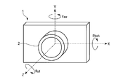
- FIG. 2 is a diagram for explaining the definition of the direction.
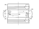
- FIG. 3 is a schematic diagram for explaining a method for selecting a mechanical shutter and an electronic shutter of an image sensor.
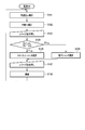
- FIG. 4 is a diagram illustrating a flowchart for explaining the operation of the imaging apparatus according to the first embodiment.
- FIG. 5 is a block diagram showing an example of the configuration of an imaging apparatus according to the second embodiment of the present invention.
- FIG. 6 is a flowchart illustrating the operation of the imaging apparatus according to the second embodiment.
- FIG. 7 is a flowchart illustrating the operation of the imaging apparatus according to the third embodiment of the present invention.
- the imaging apparatus 1 has a configuration in which an interchangeable lens 2 is attached to a camera body 3.
- the camera body 3 is configured so that the interchangeable lens 2 is detachable, and the interchangeable lens 2 is attached to the camera body 3 by a lens mount connection portion (not shown) provided in the interchangeable lens 2 and the camera body 3. This is performed by fitting a body mount connecting portion (not shown) provided to each other.
- the interchangeable lens 2 is fixed to the camera body 3, and terminals provided at each mount connection portion are also electrically connected, and the interchangeable lens 2, the camera body 3, and the like are connected via the contact points 4. Communication between the two becomes possible.
- the imaging apparatus 1 is an interchangeable lens camera in which the interchangeable lens 2 and the camera body 3 are separately provided as described above, but the present invention is not limited thereto.
- the imaging apparatus 1 may be a lens-integrated camera in which a lens is provided integrally with the camera body 3.
- the imaging device 1 does not have to include the lens mount connecting portion, the body mount connecting portion, and the contact 4 described above.
- the interchangeable lens 2 includes an optical system 21, an optical system driving unit 22, a diaphragm 23, a diaphragm driving unit 24, and a lens control unit 25.
- the interchangeable lens 2 does not necessarily include the aperture driving unit 24 and the lens control unit 25.
- the lens controller 25 can be omitted.
- the optical system 21 converges the light beam incident from the subject and forms a subject image (optical image) on the imaging surface of the imaging element 33 in the camera body.
- the optical system 21 may include a focus position adjusting lens group (hereinafter referred to as “focus lens”) and a focal length adjusting lens group (hereinafter referred to as “zoom lens”), not shown.
- focus lens focus position adjusting lens group
- zoom lens focal length adjusting lens group
- the lens constituting the optical system is not particularly limited.
- the optical system driving unit 22 moves the focus lens and the zoom lens included in the optical system 21 in the optical axis direction under the control of the lens control unit 25. Thereby, focal position adjustment (hereinafter referred to as “focusing”) and focal length adjustment (hereinafter referred to as “zooming”) are performed.
- focusing focal position adjustment
- zooming focal length adjustment
- the diaphragm 23 includes, for example, diaphragm blades that change the aperture size of the hole, and adjusts the amount of light beam incident on the imaging surface through the hole.
- the aperture driving unit 24 drives the aperture blades of the aperture 23 under the control of the lens control unit 25.
- the lens control unit 25 is configured by a CPU (Central Processing Unit) or an ASIC (Application Specific Integrated Circuit), and communicates with the camera control unit 40 in the camera body 3 via the contact 4 and performs the entire operation of the interchangeable lens 2. Control.
- the lens control unit 25 controls focusing and zooming by controlling the optical system driving unit 22 in cooperation with the camera control unit 40.
- the camera body 3 includes a mechanical shutter 31, a shutter drive unit 32, an image sensor 33, an image sensor drive unit 34, an image processing unit 35, a memory card 36, a display unit 37, an angular velocity detection unit 38, an operation unit 39, and a camera control unit 40. And a control information memory 41.
- a built-in memory or the like may be employed instead of the memory card 36.
- a device different from the camera body 3 may include an image processing unit 35, a memory card 36, a display unit 37, an angular velocity detection unit 38, an operation unit 39, a camera control unit 40, and a control information memory 41.
- the mechanical shutter 31 is a focal plane shutter disposed in front of the image sensor 33 and includes a front curtain and a rear curtain.
- the mechanical shutter 31 controls the exposure time of the image sensor 33 by adjusting the traveling timing of the front curtain and the rear curtain.
- the shutter drive unit 32 controls the running operation of the front curtain and rear curtain of the mechanical shutter 31 under the control of the camera control unit 40.
- the image sensor 33 is configured as an image sensor whose exposure can be controlled by an electronic shutter (for example, an electronic rolling shutter).
- an electronic shutter for example, an electronic rolling shutter
- Examples of the image sensor 33 include a CMOS sensor and a CCD.
- the electronic rolling shutter is a time series or a line unit for each pixel when resetting a plurality of pixels arranged in a two-dimensional manner on the imaging surface of the image sensor 33 or reading a signal. In this case, resetting or reading is performed in time series. That is, the image sensor 33 can perform the same function as the mechanical shutter 31 by electronically controlling the signal accumulation time of each pixel or each line.
- an electronic rolling shutter has been described here as an example of the electronic shutter, the present invention is not limited to this, and for example, a global shutter that exposes all pixels of the image sensor 33 at one time may be used. Absent.
- the image sensor 33 converts the subject image formed on the imaging surface into an electric signal (photoelectric conversion).
- the converted electrical signal is read out as an analog image signal under the control of the camera control unit 40, converted into a digital image signal (image data) by an AD conversion circuit (not shown), and input to the image processing unit 35.
- optical axis of the optical system 21 is adjusted at the stage of design and manufacture so as to coincide with the center of the imaging surface of the imaging device 33.
- the image sensor driving unit 34 has a configuration that supports the image sensor 33, and rotates the image sensor 33 about at least the image pickup surface center axis of the image sensor 33 as a rotation axis under the control of the camera control unit 40.
- the image sensor driving unit 34 may be configured to translate the image sensor 33 in the X direction and the Y direction.
- the X direction, Y direction, Z direction, pitch direction, yaw direction, and roll direction of the imaging apparatus 1 are as follows. Define.
- the left-right direction (horizontal direction) of the camera body 3 is the X direction. Further, in the X direction, the right direction when viewing the front of the camera body 3 is defined as + direction, and the left direction is defined as ⁇ direction. Note that the X direction also corresponds to the left-right direction of the imaging surface of the image sensor 33.
- the vertical direction of the camera body 3 is the Y direction.
- the upper direction is the + direction and the lower direction is the-direction.
- the Y direction also corresponds to the vertical direction of the imaging surface of the image sensor 33.
- the optical axis direction of the optical system 21 included in the interchangeable lens 2 is the Z direction.
- the direction from the camera body side to the interchangeable lens side is defined as a positive direction
- the direction from the interchangeable lens side to the camera body side is defined as a negative direction.
- the rotation direction with the X direction as the rotation axis is the pitch direction.
- the left rotation toward the + X direction is defined as the + direction
- the right rotation toward the + X direction is defined as the ⁇ direction.
- the rotation direction with the Y direction as the rotation axis is the yaw direction.
- a right rotation toward the + Y direction is defined as a + direction
- a left rotation toward the + Y direction is defined as a ⁇ direction.
- Rotation direction with the Z direction as the rotation axis is the roll direction.
- the left rotation toward the + Z direction is defined as the + direction
- the right rotation toward the + Z direction is defined as the ⁇ direction.
- the positive / negative (+, ⁇ ) of the direction defined in this way depends on the mounting direction of the angular velocity detection unit 38 and is not limited to the above.
- the image processing unit 35 performs various types of image processing on the image data input from the image sensor 33.
- the image processing unit 35 may also process an image read from the memory card 36.
- the memory card 36 is a recording medium that records image data processed for recording by the image processing unit 35.
- the memory card 36 is assumed to be configured to be detachable from the imaging device 1, for example. In this case, the memory card 36 may not be a configuration unique to the imaging device 1.
- the display unit 37 displays the image data processed for display by the image processing unit 35.
- an LCD Liquid Crystal Display
- the display unit 37 displays the image data processed for display by the image processing unit 35.
- an LCD Liquid Crystal Display
- the angular velocity detection unit 38 detects at least a rotation angular velocity in rotation that is a posture change in the roll direction of the imaging apparatus 1, that is, a rotation angular velocity ⁇ of rotation of the optical system 21 with the optical axis direction of the optical system 21 as a rotation axis. .
- the operation unit 39 receives a user instruction and transmits the instruction to the camera control unit 40 as an operation signal.
- the operation unit 39 includes a release button (not shown).
- This release button may be a two-stage button of a half-pressed state that is a shallow press called first release (1stR) and a fully-pressed state that is a deep press called second release (2ndR), An instruction signal corresponding to the pressed state may be output to the camera control unit 40.
- Half-pressing the release button corresponds to an AF operation instruction
- full-pressing corresponds to a shooting operation instruction.
- the AF operation is not directly related to the present invention, and any method may be adopted, and the configuration and operation description for that method are omitted.
- the camera control unit 40 is constituted by a CPU, communicates with the lens control unit 25 via the contact 4, and controls the overall operation of the camera body 3 and the imaging device 1. For example, the camera control unit 40 controls focusing and zooming in cooperation with the lens control unit 25. For example, the camera control unit 40 controls the mechanical shutter 31 and the image sensor 33. Further, for example, the camera control unit 40 receives the instruction signal transmitted from the operation unit 39, and performs processing according to the instruction signal (for example, imaging processing according to the imaging instruction signal).
- the control information memory 41 stores information such as a control program and control parameters for operating the camera body 3 in a nonvolatile manner.
- the camera control unit 40 functions as a camera shake correction control unit 401 and a shutter selection unit 402 in accordance with a control program recorded in the control information memory 41.
- the camera shake correction control unit 401 moves the image sensor 33 in a direction that at least cancels camera shake in the rotation direction.
- the image sensor driving unit 34 is controlled.
- the shutter selection unit 402 selects either the mechanical shutter 31 or the electronic shutter in the image sensor 33 based on the output of the angular velocity detection unit 38 and the control parameter recorded in the control information memory 41.
- both the camera shake correction control unit 401 and the shutter selection unit 402 may be configured as dedicated hardware separate from the camera control unit 40, or may be configured by a CPU or ASIC different from the camera control unit 40.
- the functions as the camera shake correction control unit 401 and the shutter selection unit 402 may be performed using the control program and control parameters recorded in the control information memory 41.
- the mechanical shutter 31 disposed on the front surface of the imaging surface 331 of the imaging device 33 includes a front curtain 311 and a rear curtain 312.
- Each of the front curtain 311 and the rear curtain 312 is composed of, for example, a plurality of shutter blades.
- the rear curtain 312 is retracted to a position above the image sensor 33, and the front curtain 311 is an image sensor. 33 and the optical system 21 of the interchangeable lens 2 are light-tightly covered.
- FIG. 3 shows a state during imaging (during exposure), and shows a state when the mechanical shutter 31 is driven at a speed higher than the sync speed, that is, when exposure is performed through the exposure slit 313.
- the upper end of the front curtain 311 travels in front of the image sensor 33 downward.
- the lower end of the rear curtain 312 travels downward so as to follow the upper end of the front curtain 311 at a distance of the slit interval D of the exposure slit 313.
- the traveling speed of the front curtain 311 and the rear curtain 312, that is, the curtain speed Cs is constant regardless of the shutter speed.
- the shutter speed is determined by the slit interval D, that is, the travel start timing of the trailing curtain 312.
- the front curtain 311 has reached a position below the image sensor 33.
- the rear curtain 312 optically covers the space between the image sensor 33 and the optical system 21 of the interchangeable lens 2.
- the front curtain 311 and the rear curtain 312 are linked with each other so as to overlap each other (to maintain light tightness), before imaging (before exposure). ) To move upward toward the position).
- the camera shake correction control unit 401 of the camera control unit 40 controls the image sensor driving unit 34 to detect the angular velocity detection unit.
- the image sensor 33 is moved in a direction to cancel the camera shake in the rotational direction.
- the imaging device 33 is rotated at a rotational angular velocity ⁇ in a direction that cancels camera shake in the rotational direction, with the imaging surface central axis of the imaging surface 331 of the imaging device 33 as the rotational axis. .
- the pixel that has moved downward moves away from the rear curtain 312 of the mechanical shutter 31 that travels at a constant speed, it is shielded by the rear curtain 312 later than the original, and the time that is longer than the original exposure time, It will be exposed.
- the pixel moved upward becomes a dark spot (d point)
- the pixel moved downward becomes a bright spot (b point).
- the pixels at the concentric positions with the two pixels on the long side end of the image sensor 33 are also bright spots or dark spots.
- the shutter selection unit 402 of the camera control unit 40 starts from the mechanical shutter 31 to the image sensor 33.
- the shutter to be used is switched to the electronic shutter.
- the light quantity ratio L indicated by is for a predetermined threshold L lim L ⁇ L lim (2) At the time of switching to the electronic shutter.
- the predetermined threshold L lim is L lim > 1 (3) It is.
- This predetermined threshold value L lim is a design value arbitrarily determined by the manufacturer of the imaging apparatus 1 as in the case of color shade, and the value is not particularly limited here.
- This predetermined threshold value L lim is recorded in the control information memory 41 as one of the control parameters.
- the shutter selection unit 402 selects a shutter to be used as follows.
- the curtain speed of the front curtain 311 and the rear curtain 312 of the mechanical shutter 31 is C s
- the slit interval (less than the short side length) is D
- the rotational angular velocity (unrelated to the rotation direction) is ⁇
- T d D / (C s + ⁇ x) (5) It is.
- Equation (2) is (C s + ⁇ x) / (C s ⁇ x) ⁇ L lim (8) It becomes.
- the curtain speed C s the distance x from the center of the imaging surface 331 to the long side edge, and the predetermined threshold L lim are design values, and are fixed values recorded in the control information memory 41 as control parameters.
- the shutter selection unit 402 calculates the left side of the equation (9) based on the rotational angular velocity ⁇ that can be detected by the angular velocity detection unit 38, and switches to the electronic shutter if the equation (9) is satisfied.
- the camera control unit 40 executes a function as a camera shake correction control unit 401 in accordance with a control program recorded in the control information memory 41. That is, the camera shake correction control unit 401 of the camera control unit 40 detects the rotation angular velocity in the roll direction of the imaging apparatus 1 detected by the angular velocity detection unit 38, that is, the optical system 21 having the imaging surface central axis of the imaging device 33 as the rotation axis. (Step S101), and based on this rotational angular velocity ⁇ , the image sensor driving unit 34 is controlled so as to move the image sensor 33 in a direction to cancel the shaking in the rotational direction (step S102).
- the function of the camera shake correction control unit 401 continues to be executed until the power is turned off. Needless to say, not only the camera shake correction in the rotation direction but also the camera shake correction in the horizontal direction, the vertical direction, the yaw direction, and the pitch direction of the imaging surface 331 of the imaging device 33 may be performed.
- the camera control unit 40 executes a function as the shutter selection unit 402 according to the control program recorded in the control information memory 41. That is, the shutter selection unit 402 of the camera control unit 40 calculates the left side of the equation (9) using the rotation angular velocity ⁇ , and determines whether or not the equation (9) is satisfied (step S104). If the expression (9) is not satisfied, the mechanical shutter 31 is selected as the shutter to be used (step S105). On the other hand, if the expression (9) is satisfied, the electronic shutter of the image sensor 33 is selected as the shutter to be used (step S105).
- step S106 When the release button of the operation unit 39 is fully pressed (step S106), the camera control unit 40 performs an imaging operation using the selected shutter (step S107). That is, when the mechanical shutter 31 is selected, the camera control unit 40 controls the shutter driving unit 32 and performs imaging using the mechanical shutter 31. When the electronic shutter is selected, the camera control unit 40 controls the image sensor 33 and performs imaging using the electronic shutter.
- the imaging device 1 includes the imaging device 33 including the imaging surface 331 that photoelectrically converts the subject image, and the imaging device 33 with respect to the predetermined rotation axis that passes through the center of the imaging surface 331.
- An image sensor driving unit 34 that is a drive unit for rotating the image sensor, an angular velocity detecting unit 38 that detects a rotational angular velocity of the imaging device 1 with respect to a predetermined rotational axis, and a predetermined rotation axis of the imaging device 1 based on the rotational angular velocity.
- a shake correction control unit 401 that is a rotational shake reduction control unit that controls the image sensor drive unit 34 so as to reduce rotational shake caused by a change in posture of the camera, and a mechanical first that controls the exposure time of the image sensor 33.
- the mechanical shutter 31 that is the shutter unit of the image sensor
- the electronic shutter of the image sensor 33 that is the electronic second shutter unit that controls the exposure time of the image sensor 33
- a shutter selecting section 402 that selects one of the electronic shutter of Karushatta 31 and the imaging element 33, and a.
- the shutter to be used can be switched in accordance with the rotational angular velocity, an imaging apparatus that does not cause unevenness in the exposure amount even if a large rotational camera shake occurs during exposure can be provided. That is, if it is assumed that uneven exposure will occur if the mechanical shutter 31 is used, uneven exposure due to running of the front curtain and the rear curtain occurs by switching the mechanical shutter 31 to the electronic shutter with the mechanical shutter 31 fully open. Absent.
- the predetermined rotation axis is the central axis of the image pickup surface of the image pickup device, and coincides with the optical axis of the optical system 21. The same effect can be obtained in both the lens interchangeable image pickup apparatus and the lens integrated image pickup apparatus. can get.
- the shutter selection unit 402 sets the curtain speed of the mechanical shutter 31 to C s , the rotational angular velocity to ⁇ , the distance from the center of the imaging surface 331 to the long side edge of the imaging surface 331, and the predetermined threshold value to L lim .
- the rotational angular velocity ⁇ is (C s + ⁇ x) / (
- the electronic shutter may be selected when the conditional expression is satisfied. That is, when the rotational angular velocity ⁇ is in a speed range in which unevenness in exposure amount is likely to occur, the occurrence of unevenness in exposure amount can be suppressed by switching from the mechanical shutter 31 to the electronic shutter.
- the imaging device 1 further includes a gravity direction detection unit 42 that detects the direction of gravity, and the imaging element driving unit 34 is configured so that one side of the imaging element 33 is parallel to the gravity direction.
- the image sensor 33 may be rotated.
- camera shake correction is triggered by power-on and shutter selection is triggered by half-pressing the release button
- present invention is not limited thereto.
- camera shake correction may be triggered by half-pressing the release button.
- the present invention does not assume a release button having a two-stage button.
- the imaging apparatus 1 estimates a shake amount at the time of imaging, and performs correction driving according to the estimated shake amount, thereby correcting the shake correction function.
- the accuracy of the is improved.
- the configuration example according to the second embodiment and a part of the operation according to the second embodiment are the same as those according to the first embodiment, and the same components are the same as those according to the first embodiment. The description is omitted by attaching the reference numerals.
- the camera control unit 40 sets the rotation angular velocity ⁇ ′ during exposure.
- An angular velocity estimation unit 403 for estimation is provided.
- the camera shake correction control unit 401 of the camera control unit 40 performs camera shake correction control based on the estimated rotational angular velocity ⁇ ′.
- the shutter selection unit 402 of the camera control unit 40 detects the angular velocity detection unit 38 in the first embodiment.
- the rotational angular velocity in the roll direction that is, the rotational angular velocity ⁇ of the optical system 21 having the optical axis direction of the optical system 21 as the rotational axis
- the rotational angular velocity ⁇ ′ during exposure estimated by the angular velocity estimating unit 403 is used. That is, the following equation (10) is used instead of the equation (9) in the first embodiment. (C s + ⁇ ′x) / (
- any of the camera shake correction control unit 401, the shutter selection unit 402, and the angular velocity estimation unit 403 may be configured as dedicated hardware separate from the camera control unit 40, or different from the camera control unit 40.
- the functions of the camera shake correction control unit 401, the shutter selection unit 402, and the angular velocity estimation unit 403 may be achieved by using a control program and control parameters configured by a CPU or ASIC and recorded in the control information memory 41.
- the camera control unit 40 executes functions as an angular velocity estimation unit 403 and a camera shake correction control unit 401 in accordance with a control program recorded in the control information memory 41. That is, the angular velocity estimation unit 403 of the camera control unit 40 rotates the optical system 21 with the rotational angular velocity in the roll direction of the imaging device 1 detected by the angular velocity detection unit 38, that is, the optical axis direction of the optical system 21 as the rotation axis.
- the angular velocity ⁇ is taken in (step S201) and recorded in the control information memory 41 or a temporary memory (not shown) (step S202).
- the rotational angular velocity ⁇ ′ at the time of exposure is estimated based on the rotational angular velocity ⁇ stored in the control information memory 41 or a temporary memory (not shown) from when the power is turned on (step S203).
- the camera shake correction control unit 401 of the camera control unit 40 moves the image sensor driving unit 34 so as to move the image sensor 33 in a direction to cancel the camera shake in the rotation direction.
- Control step S204).
- the functions of the angular velocity estimation unit 403 and the camera shake correction control unit 401 continue to be executed until the power is turned off. Needless to say, not only the camera shake correction in the rotation direction but also the camera shake correction in the horizontal direction, the vertical direction, the yaw direction, and the pitch direction of the imaging surface 331 of the imaging device 33 may be performed.
- the camera control unit 40 executes a function as the shutter selection unit 402 in accordance with a control program recorded in the control information memory 41. That is, the shutter selection unit 402 of the camera control unit 40 calculates the left side of the equation (10) using the estimated rotation angular velocity ⁇ ′ at the time of exposure, and determines whether or not the equation (10) is satisfied (step). S205). If the expression (10) is not satisfied, the mechanical shutter 31 is selected as the shutter to be used (step S105). On the other hand, when the expression (10) is satisfied, the electronic shutter of the image sensor 33 is selected as the shutter to be used (step S105).
- step S106 When the release button of the operation unit 39 is fully pressed (step S106), the camera control unit 40 performs an imaging operation using the selected shutter (step S107). That is, when the mechanical shutter 31 is selected, the camera control unit 40 controls the shutter driving unit 32 and performs imaging using the mechanical shutter 31. When the electronic shutter is selected, the camera control unit 40 controls the image sensor 33 and performs imaging using the electronic shutter.
- the imaging device 1 includes the imaging device 33 including the imaging surface 331 that photoelectrically converts the subject image, and the imaging device 33 with respect to the predetermined rotation axis that passes through the center of the imaging surface 331.
- An image sensor driving unit 34 that is a drive unit for rotating the image sensor, an angular velocity detecting unit 38 that detects the rotational angular velocity of the imaging device 1 with respect to a predetermined rotation axis, and an estimated rotation by estimating the rotational angular velocity of the imaging device 1 at the time of exposure.
- An angular velocity estimation unit 403 that obtains an angular velocity, and a rotational shake reduction that controls the image sensor driving unit 34 based on the estimated rotational angular velocity so as to reduce the rotational shake caused by the posture change around the predetermined rotation axis of the imaging device 1.
- the camera shake correction control unit 401 that is a control unit, the mechanical shutter 31 that is a mechanical first shutter unit that controls the exposure time of the image sensor 33, and the exposure time of the image sensor 33 are controlled.
- An electronic shutter of the image sensor 33 that is an electronic second shutter unit; and a shutter selector 402 that selects either the mechanical shutter 31 or the electronic shutter of the image sensor 33 according to the estimated rotational angular velocity. ing. That is, since the shutter to be used can be switched according to the estimated rotational angular velocity, it is possible to provide an imaging device that does not cause unevenness in the exposure amount even if a large rotational camera shake occurs during exposure.
- the shutter selection unit 402 sets the curtain speed of the mechanical shutter 31 to C s , the estimated rotational angular speed ⁇ ′, the distance from the center of the imaging surface 331 to the long side edge of the imaging surface 331, and a predetermined threshold value L lim.
- the estimated rotational angular velocity ⁇ ′ is (C s + ⁇ ′x) / (
- the electronic shutter is selected when the following conditional expression is satisfied. That is, when the estimated rotational angular velocity ⁇ ′ is in a speed range in which unevenness in exposure amount is likely to occur, the occurrence of unevenness in exposure amount can be suppressed by switching from the mechanical shutter 31 to the electronic shutter.
- the angular velocity estimation unit 403 is configured to estimate the rotation angular velocity ⁇ ′ of the imaging device 1 at the time of exposure based on the rotation angular velocity detected by the angular velocity detection unit 38 before exposure.
- the estimated rotational angular velocity ⁇ ′ is estimated using power-on as a trigger, and camera shake correction and shutter selection are performed based on the estimated rotational angular velocity ⁇ ′.
- the control information memory 41 is further provided as a storage unit for storing the rotation angular velocity detected by the angular velocity detection unit 38, and the angular velocity estimation unit 403 is based on the rotation angular velocity stored in the control information memory 41, during exposure.
- the rotational angular velocity ⁇ ′ of the imaging device 1 is estimated. Accordingly, since many rotational angular velocities used for estimation can be detected, it is possible to estimate the rotational angular velocity ⁇ ′ of the imaging apparatus 1 during exposure in consideration of shakes caused by factors other than the operator's hand shake such as imaging on the ship. It becomes possible. In addition, by accumulating a large number of detected rotational angular velocities ⁇ , it is possible to estimate the rotational angular velocities ⁇ ′ of the imaging apparatus 1 during exposure in consideration of wrinkles and tendencies of operator shake.
- the imaging device 1 further includes a gravity direction detection unit 42 that detects the direction of gravity, and the imaging element driving unit 34 is configured so that one side of the imaging element 33 is parallel to the gravity direction.
- the image sensor 33 may be rotated.
- the present invention is not limited thereto. . Further, it is not premised on a two-stage release button.
- the imaging apparatus 1 according to the present embodiment can perform camera shake correction using the estimated rotational angular velocity ⁇ ′ as in the second embodiment, but the accumulation period of the rotational angular velocity ⁇ used for the estimation is the second implementation. It is different from the form. Therefore, the configuration example according to the third embodiment is the same as that according to the second embodiment, and the description thereof is omitted. In addition, a part of the operation according to the third embodiment is the same as that according to the second embodiment, and the same components are denoted by the same reference numerals as those of the second embodiment, and the description thereof will be given. Omitted.
- any of the camera shake correction control unit 401, the shutter selection unit 402, and the angular velocity estimation unit 403 may be configured as dedicated hardware that is separate from the camera control unit 40, or camera control.
- the control unit 401 functions as a camera shake correction control unit 401, a shutter selection unit 402, and an angular velocity estimation unit 403 using a control program and control parameters that are configured by a CPU and ASIC different from the unit 40 and recorded in the control information memory 41. You may do it.
- the camera control unit 40 After the power of the imaging device 1 is turned on, the camera control unit 40 waits for the release button of the operation unit 39 to be half-pressed.
- the camera control unit 40 executes functions as an angular velocity estimation unit 403 and a camera shake correction control unit 401 in accordance with a control program recorded in the control information memory 41. That is, the angular velocity estimation unit 403 of the camera control unit 40 rotates the optical system 21 with the rotational angular velocity in the roll direction of the imaging device 1 detected by the angular velocity detection unit 38, that is, the optical axis direction of the optical system 21 as the rotation axis.
- the angular velocity ⁇ is taken in (step S201) and recorded in the control information memory 41 or a temporary memory (not shown) (step S202). Then, the rotational angular velocity ⁇ ′ at the time of exposure is estimated based on the rotational angular velocity ⁇ stored in the control information memory 41 or a temporary memory (not shown) after the release button is pressed halfway (step S203). Based on the estimated rotation angular velocity ⁇ ′ at the time of exposure, the camera shake correction control unit 401 of the camera control unit 40 moves the image sensor driving unit 34 so as to move the image sensor 33 in a direction to cancel the camera shake in the rotation direction. Control (step S204).
- the functions of the angular velocity estimation unit 403 and the camera shake correction control unit 401 continue to be executed until the release button is released (half press or full press). Needless to say, not only the camera shake correction in the rotation direction but also the camera shake correction in the horizontal direction, the vertical direction, the yaw direction, and the pitch direction of the imaging surface 331 of the imaging device 33 may be performed.
- the camera control unit 40 executes a function as the shutter selection unit 402 in accordance with a control program recorded in the control information memory 41. That is, the shutter selection unit 402 of the camera control unit 40 calculates the left side of the equation (10) using the estimated rotation angular velocity ⁇ ′ at the time of exposure, and determines whether or not the equation (10) is satisfied (step). S205). If the expression (10) is not satisfied, the mechanical shutter 31 is selected as the shutter to be used (step S105). On the other hand, when the expression (10) is satisfied, the electronic shutter of the image sensor 33 is selected as the shutter to be used (step S105).
- step S106 When the release button of the operation unit 39 is fully pressed (step S106), the camera control unit 40 performs an imaging operation using the selected shutter (step S107). That is, when the mechanical shutter 31 is selected, the camera control unit 40 controls the shutter driving unit 32 and performs imaging using the mechanical shutter 31. When the electronic shutter is selected, the camera control unit 40 controls the image sensor 33 and performs imaging using the electronic shutter.
- the imaging apparatus 1 further includes an operation unit 39 that receives an operation by an operator, and the angular velocity estimation unit 403 has a rotational angular velocity detected by the angular velocity detection unit 38 according to the operation of the operation unit 39. Based on this, the rotational angular velocity ⁇ ′ of the imaging device 1 at the time of exposure is estimated. In other words, the estimated rotational angular velocity ⁇ ′ is estimated by half-pressing the release button of the operation unit 39, and camera shake correction and shutter selection are performed based on the estimated rotational angular velocity ⁇ ′.
- control information memory 41 is further provided as a storage unit for storing the rotation angular velocity detected by the angular velocity detection unit 38, and the angular velocity estimation unit 403 is based on the rotation angular velocity stored in the control information memory 41, during exposure.
- the rotational angular velocity ⁇ ′ of the imaging device 1 is estimated. Therefore, by accumulating the detected rotational angular velocity ⁇ close to that at the time of exposure, it is possible to estimate the rotational angular velocity ⁇ ′ that is close to the actual movement at the time of exposure.
- the present invention is not limited thereto.
- an operation by an operator other than half-pressing the release button may be a trigger. That is, it may be configured so that the operator can select.
- the present invention does not assume a release button having a two-stage button.
- the present invention is not limited to the above-described embodiment as it is, and can be embodied by modifying the constituent elements without departing from the scope of the invention in the implementation stage.
- Various inventions can be formed by appropriately combining a plurality of constituent elements disclosed in the embodiments. For example, you may delete some components from all the components shown by embodiment. Furthermore, the constituent elements over different embodiments may be appropriately combined. Thus, it goes without saying that various modifications and applications are possible without departing from the spirit of the invention.
- each processing by the imaging apparatus 1 in the above-described embodiment may be stored as a program that can be executed.
- This program is stored in a storage medium of an external storage device such as a memory card (ROM card, RAM card, etc.), magnetic disk (floppy (registered trademark) disk, hard disk, etc.), optical disc (CD-ROM, DVD, etc.), semiconductor memory, etc.
- the above-described processing can be executed by reading the stored program and controlling the operation by the read program.
Landscapes
- Engineering & Computer Science (AREA)
- Multimedia (AREA)
- Signal Processing (AREA)
- Physics & Mathematics (AREA)
- General Physics & Mathematics (AREA)
- Studio Devices (AREA)
- Adjustment Of Camera Lenses (AREA)
Abstract
本発明の一態様の撮像装置(1)は、撮像素子(33)の撮像面の中心を通る所定の回転軸に対して撮像素子を回転移動させる撮像素子駆動部(34)と、前記所定の回転軸に関する撮像装置の回転角速度を検出する角速度検出部(38)と、前記回転角速度に基づいて、撮像装置の前記所定の回転軸周りの姿勢変化に伴って生じる回転振れが低減するように撮像素子駆動部を制御する手振れ補正制御部(401)と、前記回転角速度に応じて、メカニカルシャッタ(31)と撮像素子の電子シャッタとの何れかを選択するシャッタ選択部(402)と、を備える。
Description
本発明は、メカニカルシャッタと電子シャッタとを併用して撮像動作を行う撮像装置に関する。
例えば特許文献1や特許文献2に開示されているように、従来より、メカニカルシャッタと電子シャッタとを併用して撮像動作を行う撮像装置が知られている。
一方、特許文献2に開示されているように、手振れによる撮像画像の画質低下を抑制するための手振れ補正機能を内蔵した撮像装置も多くなってきている。この手振れ補正機能は、角速度センサ等により撮像装置に与えられる振れ量を検出し、その振れ量に応じて撮像素子等の構造物を振れ補正駆動するものである。
また、特許文献3に開示されているように、撮像時の振れ量を推定し、その推定した振れ量に応じた補正駆動を行うことで、手振れ補正機能における補正の精度を上げる手法も提案されている。
ここで、ユーザが撮像装置を使用する場合、撮像装置を構成する光学系の光軸を中心とした回転方向に、手振れが生じる場合がある。このような回転手振れが生じた場合、手振れ補正機能は、その回転手振れが低減するように撮像素子を高速に回転駆動する。
一方、フォーカルプレーンシャッタ等のメカニカルシャッタは、撮像素子が回転していない定常状態における撮像素子の水平及び垂直方向と合致するように、その水平及び垂直方向が設定されて撮像装置内に固定配置されている。そのため、回転手振れを低減するために撮像素子が回転すると、メカニカルシャッタの水平方向と撮像素子の水平方向とがずれる。
従って、露光中に、大きな回転手振れが発生すると、メカニカルシャッタの動作により本来なら同一露光時間となるべき撮像素子の同一画素列上の画素間で、露光時間の不一致が発生し、露光量のむらが生じてしまう。
本発明は、露光中に大きな回転手振れが発生したとしても露光量のむらが生じない撮像装置を提供することを目的とする。
本発明の第1の態様によれば、被写体像を光電変換する撮像面を備える撮像素子と、撮像面の中心を通る所定の回転軸に対して撮像素子を回転移動させる駆動部と、所定の回転軸に関する撮像装置の回転角速度を検出する角速度検出部と、回転角速度に基づいて、撮像装置の所定の回転軸周りの姿勢変化に伴って生じる回転振れが低減するように駆動部を制御する回転振れ低減制御部と、撮像素子の露光時間を制御する機械式の第1のシャッタ部と、撮像素子の露光時間を制御する電子式の第2のシャッタ部と、回転角速度に応じて、第1のシャッタ部、又は、第2のシャッタ部の何れかを選択するシャッタ選択部と、を備えた撮像装置が提供される。
また、本発明の第2の態様によれば、被写体像を光電変換する撮像面を備える撮像素子と、撮像面の中心を通る所定の回転軸に対して撮像素子を回転移動させる駆動部と、所定の回転軸に関する撮像装置の回転角速度を検出する角速度検出部と、露光時の撮像装置の回転角速度を推定して推定回転角速度を得る角速度推定部と、推定回転角速度に基づいて、撮像装置の所定の回転軸周りの姿勢変化に伴って生じる回転振れが低減するように駆動部を制御する回転振れ低減制御部と、撮像素子の露光時間を制御する機械式の第1のシャッタ部と、撮像素子の露光時間を制御する電子式の第2のシャッタ部と、推定回転角速度に応じて、第1のシャッタ部、又は、第2のシャッタ部の何れかを選択するシャッタ選択部と、を備えた撮像装置が提供される。
また、本発明の第2の態様によれば、被写体像を光電変換する撮像面を備える撮像素子と、撮像面の中心を通る所定の回転軸に対して撮像素子を回転移動させる駆動部と、所定の回転軸に関する撮像装置の回転角速度を検出する角速度検出部と、露光時の撮像装置の回転角速度を推定して推定回転角速度を得る角速度推定部と、推定回転角速度に基づいて、撮像装置の所定の回転軸周りの姿勢変化に伴って生じる回転振れが低減するように駆動部を制御する回転振れ低減制御部と、撮像素子の露光時間を制御する機械式の第1のシャッタ部と、撮像素子の露光時間を制御する電子式の第2のシャッタ部と、推定回転角速度に応じて、第1のシャッタ部、又は、第2のシャッタ部の何れかを選択するシャッタ選択部と、を備えた撮像装置が提供される。
本発明によれば、検出した回転角速度に応じて又は推定した回転角速度に応じて使用するシャッタを切り替えることができるので、露光中に大きな回転手振れが発生したとしても露光量のむらが生じない撮像装置を提供することができる。
[第1実施形態]
図1に示すように、第1実施形態に係る撮像装置1は、交換レンズ2がカメラ本体3に装着された構成を有する。なお、カメラ本体3は、交換レンズ2を着脱自在に構成されており、カメラ本体3への交換レンズ2の装着は、交換レンズ2に設けられている図示しないレンズマウント接続部とカメラ本体3に設けられている図示しないボディマウント接続部とが互いに嵌合することによって行われる。これにより、交換レンズ2がカメラ本体3に固定されると共に、各々のマウント接続部に設けられている端子同士も電気的に接続され、その接点4を介して、交換レンズ2とカメラ本体3との間での通信が可能になる。
図1に示すように、第1実施形態に係る撮像装置1は、交換レンズ2がカメラ本体3に装着された構成を有する。なお、カメラ本体3は、交換レンズ2を着脱自在に構成されており、カメラ本体3への交換レンズ2の装着は、交換レンズ2に設けられている図示しないレンズマウント接続部とカメラ本体3に設けられている図示しないボディマウント接続部とが互いに嵌合することによって行われる。これにより、交換レンズ2がカメラ本体3に固定されると共に、各々のマウント接続部に設けられている端子同士も電気的に接続され、その接点4を介して、交換レンズ2とカメラ本体3との間での通信が可能になる。
なお、本実施形態に係る撮像装置1は、このように、交換レンズ2とカメラ本体3とが別体として設けられているレンズ交換式のカメラであるものとするが、本発明はこれに限らず、撮像装置1は、レンズがカメラ本体3に一体として設けられたレンズ一体式のカメラであっても良い。この場合、撮像装置1は、上述した、レンズマウント接続部、ボディマウント接続部、接点4を備えなくてよい。
交換レンズ2は、光学系21、光学系駆動部22、絞り23、絞り駆動部24、及びレンズ制御部25を含む。ただし、交換レンズ2は、絞り駆動部24、及びレンズ制御部25を、必ずしも含む必要はない。例えば、光学系21の制御を手動で行う場合には、レンズ制御部25を省略することができる。
光学系21は、被写体から入射した光束を収束させて被写体像(光学像)をカメラ本体内の撮像素子33の撮像面に結像する。なお、光学系21は、図示しない焦点位置調整用のレンズ群(以下「フォーカスレンズ」という)や焦点距離調整用のレンズ群(以下「ズームレンズ」という)を含んでいても良い。光学系を構成するレンズは、特に限定されない。
光学系駆動部22は、レンズ制御部25の制御の下、光学系21に含まれるフォーカスレンズやズームレンズを光軸方向に移動させる。これにより焦点位置調整(以下「フォーカシング」という)や焦点距離調整(以下「ズーミング」という)が行われる。
絞り23は、孔の開口サイズを可変する例えば絞り羽根を含み、孔を通って撮像面に入射する光束の量を調整する。
絞り駆動部24は、レンズ制御部25の制御の下、この絞り23の絞り羽根を駆動する。
レンズ制御部25は、CPU(Central Proceccing Unit)またはASIC(Apprication Specific Integrated Circuit)により構成され、接点4を介してカメラ本体3内のカメラ制御部40と通信すると共に、交換レンズ2の全体動作を制御する。例えば、レンズ制御部25は、カメラ制御部40と協働して光学系駆動部22を制御することにより、フォーカシングやズーミングを制御する。
カメラ本体3は、メカニカルシャッタ31、シャッタ駆動部32、撮像素子33、撮像素子駆動部34、画像処理部35、メモリカード36、表示部37、角速度検出部38、操作部39、カメラ制御部40、及び制御情報メモリ41を含む。ただし、メモリカード36に代えて、内蔵メモリ等を採用しても良い。また、カメラ本体3とは異なる機器が画像処理部35、メモリカード36、表示部37、角速度検出部38、操作部39、カメラ制御部40、及び制御情報メモリ41を備えていてもよい。
メカニカルシャッタ31は、撮像素子33の前面に配置されたフォーカルプレーンシャッタであり、先幕と、後幕と、を備えている。メカニカルシャッタ31は、先幕と後幕のそれぞれの走行タイミングを調整することによって撮像素子33の露光時間を制御する。
シャッタ駆動部32は、カメラ制御部40の制御の下にメカニカルシャッタ31の先幕及び後幕の走行動作を制御する。
撮像素子33は、電子シャッタ(例えば電子ローリングシャッタ)により露光制御可能な撮像素子として構成されたものであり、一例としてはCMOSセンサや、CCDが挙げられる。ここに、電子ローリングシャッタとは、撮像素子33の撮像面に2次元状に配列されている複数の画素をリセットする際、または信号を読み出す際に、画素毎に時系列的に、あるいはライン単位で時系列的に、リセットまたは読み出しを行うものをいう。すなわち、撮像素子33は、各画素または各ラインの信号蓄積時間を電子的に制御することにより、メカニカルシャッタ31と同様の機能を果たすことができる。
なお、ここでは電子シャッタの例として電子ローリングシャッタを挙げたが、本発明はこれに限定されるものはなく、例えば、撮像素子33の全画素を一度に露光するグローバルシャッタ等であっても構わない。
撮像素子33は、撮像面に結像された被写体像を電気信号に変換する(光電変換する)。変換された電気信号は、カメラ制御部40の制御の下にアナログ画像信号として読み出され、図示しないAD変換回路により、デジタル画像信号(画像データ)に変換されて、画像処理部35に入力される。
なお、光学系21の光軸は、撮像素子33の撮像面中心と一致するように設計や製造の段階で調整されている。
撮像素子駆動部34は、撮像素子33を支持する構成を有し、カメラ制御部40の制御の下に、少なくとも撮像素子33の撮像面中心軸を回転軸として撮像素子33を回転移動させる。撮像素子駆動部34は、撮像素子33をX方向及びY方向に並進移動させるように構成されていてもよい。
ここで、図2を参照して、方向の定義を説明する。本実施形態においては、図2に示すように、撮像装置1のX方向、Y方向、Z方向、ピッチ(Pitch)方向、ヨー(Yaw)方向、及びロール(Roll)方向を、次のように定義する。
カメラ本体3の左右方向(水平方向)をX方向とする。また、そのX方向において、カメラ本体3の正面を見たときの右方向を+方向とし、その左方向を-方向とする。なお、X方向は、撮像素子33の撮像面の左右方向にも対応する。
カメラ本体3の上下方向(垂直方向)をY方向とする。また、そのY方向において、上方向を+方向とし、下方向を-方向とする。なお、Y方向は、撮像素子33の撮像面の上下方向にも対応する。
交換レンズ2に含まれる光学系21の光軸方向をZ方向とする。また、そのZ方向において、カメラ本体側から交換レンズ側への方向を+方向とし、交換レンズ側からからカメラ本体側への方向を-方向とする。
X方向を回転軸とする回転方向をピッチ方向とする。また、そのピッチ方向において、+X方向へ向かって左回転を+方向とし、+X方向に向かって右回転を-方向とする。
Y方向を回転軸とする回転方向をヨー方向とする。また、そのヨー方向において、+Y方向へ向かって右回転を+方向とし、+Y方向に向かって左回転を-方向とする。
Z方向を回転軸とする回転方向をロール方向とする。また、そのロール方向において、+Z方向に向かって左回転を+方向とし、+Z方向に向かって右回転を-方向とする。
なお、このように定義した方向の正負(+,-)は、角速度検出部38の実装方向に依存するため、前記に限定されるものでないことは勿論のことである。
画像処理部35は、撮像素子33から入力された画像データに各種の画像処理を施すものである。また、画像処理部35は、メモリカード36から読み出した画像の処理も行うようになっていてもよい。
メモリカード36は、画像処理部35により記録用に処理された画像データを記録する記録媒体である。このメモリカード36は、例えば撮像装置1に着脱可能に構成されているものが想定され、この場合には撮像装置1に固有の構成でなくても構わない。
表示部37は、画像処理部35により表示用に処理された画像データを表示するものである。例えば、画面の画素の電圧のON/OFFを制御して、画像データに基づく画像を表示するLCD(Liquid Crystal Display)等である。
角速度検出部38は、少なくとも、撮像装置1のロール方向の姿勢変化である回転における回転角速度、つまり、光学系21の光軸方向を回転軸とする光学系21の回転の回転角速度ωを検出する。
操作部39は、ユーザの指示を受け取り、その指示を操作信号としてカメラ制御部40へ伝達する。操作部39は、図示しないレリーズ釦を含む。このレリーズ釦は、ファーストレリーズ(1stR)と呼称される浅い押圧である半押し状態と、セカンドレリーズ(2ndR)と呼称される深い押圧である全押し状態との2段階釦であってもよく、その押圧状態に応じた指示信号をカメラ制御部40に出力してもよい。レリーズ釦の半押しは、AF動作の指示に対応し、全押しは、撮影動作の指示に対応している。なお、AF動作については本発明に直接関係なく、何れの方法を採用してもよいため、そのための構成及び動作説明は省略する。
カメラ制御部40は、CPUにより構成され、接点4を介してのレンズ制御部25との通信を行うと共に、カメラ本体3及び撮像装置1の全体動作を制御する。例えば、カメラ制御部40は、レンズ制御部25と協働してフォーカシングやズーミングを制御する。また、例えば、カメラ制御部40は、メカニカルシャッタ31及び撮像素子33を制御する。また、例えば、カメラ制御部40は、操作部39から送信された指示信号を受信し、その指示信号に応じた処理(例えば撮影指示信号に応じた撮影処理)を行う。
制御情報メモリ41は、カメラ本体3を動作させるための制御プログラムや制御パラメータ等の情報を不揮発的に記録している。
また、本実施形態においては、カメラ制御部40は、制御情報メモリ41に記録されている制御プログラムに従って、手振れ補正制御部401及びシャッタ選択部402としての機能を果たす。
手振れ補正制御部401は、角速度検出部38の出力と撮像素子33の回転中心位置(撮像面中心位置でもある)とに基づいて、少なくとも回転方向の手振れを打ち消す方向に撮像素子33を移動させるように撮像素子駆動部34を制御する。
シャッタ選択部402は、角速度検出部38の出力と制御情報メモリ41に記録されている制御パラメータとに基づいて、メカニカルシャッタ31と撮像素子33における電子シャッタとの何れかを選択する。
なお、手振れ補正制御部401及びシャッタ選択部402の何れも、カメラ制御部40とは別体の専用のハードウェアとして構成しても良いし、カメラ制御部40とは別のCPUやASICにより構成して制御情報メモリ41に記録されている制御プログラムや制御パラメータを用いて手振れ補正制御部401及びシャッタ選択部402としての機能を果たすようにしても良い。
ここで、このシャッタ選択部402によるメカニカルシャッタ31と撮像素子33の電子シャッタの選択手法を説明する。
図3に示すように、撮像素子33の撮像面331の前面に配置されるメカニカルシャッタ31は、先幕311と後幕312とを備えている。先幕311及び後幕312は、それぞれ、例えば複数枚のシャッタ羽根により構成されたものとなっている。
なお、図示はしていないが、このようなメカニカルシャッタ31では、撮像前(露光前)においては、後幕312は撮像素子33よりも上側の位置に退避しており、先幕311は撮像素子33と交換レンズ2の光学系21との間を光密に覆っている。
図3は撮像中(露光中)の様子を示すものであり、シンクロ速度以上でメカニカルシャッタ31が駆動されているとき、つまり、露光スリット313を介して露光が行われているときの様子を図示している。先幕311の上端は撮像素子33の前方を下方へ向けて走行している。一方、後幕312の下端は、露光スリット313のスリット間隔Dだけ間隔をおいて、先幕311の上端を追いかけるように下方へ向けて走行している。ここで、先幕311及び後幕312の走行速度つまり幕速Csは、シャッタ速度によらず一定である。シャッタ速度は、スリット間隔D、つまり、後幕312の走行開始タイミングにより決定される。
そして、図示はしていないが、撮像(露光)が終了したときには、先幕311は、撮像素子33よりも下側の位置に到達している。一方、後幕312は、撮像素子33と交換レンズ2の光学系21との間を光密に覆っている。
そして、図示はしていないが、シャッタチャージを行うときには、先幕311及び後幕312は、互いに重畳する部分を有するように(光密を維持するように)連携しながら、撮像前(露光前)の位置へ向かって上方へ移動するものである。
このようなメカニカルシャッタ31を使用した撮像中(露光中)に、回転方向の手振れが発生すると、カメラ制御部40の手振れ補正制御部401は、撮像素子駆動部34を制御して、角速度検出部38で検出した回転角速度ωに基づいて、その回転方向の手振れを打ち消す方向に撮像素子33を移動させる。これにより、撮像素子33は、図3に示すように、撮像素子33の撮像面331の撮像面中心軸を回転軸として、回転方向の手振れを打ち消す方向に回転角速度ωで回転されることになる。
このとき、この回転軸を原点(X=0)とするX方向において当該原点から距離xだけ離れた長辺端の2点の画素は、互いに上下反対方向に同一速度ωxで移動する。そして、上方向に移動した画素は、一定速度で走行するメカニカルシャッタ31の後幕312に近づくため、本来よりも早く後幕312で遮光されることとなり、本来の露光時間よりも短い時間しか露光されなくなる。逆に、下方向に移動した画素は、一定速度で走行するメカニカルシャッタ31の後幕312から遠ざかるため、本来よりも遅く後幕312で遮光されることとなり、本来の露光時間よりも長い時間、露光されることとなる。こうして、上方向に移動した画素は暗点(d点)となり、下方向に移動した画素は輝点(b点)となってしまう。
このような撮像素子33の長辺端の2点の画素と同心円位置の各画素についても、同様に、輝点または暗点となってしまう。
そこで、本実施形態では、このような輝点と暗点との光量比Lが所定の閾値Llim以上の場合には、カメラ制御部40のシャッタ選択部402が、メカニカルシャッタ31から撮像素子33の電子シャッタに、使用するシャッタを切り替えるものである。
即ち、輝点の光量をLb、暗点の光量をLdとしたとき、
L=Lb/Ld (1)
で示される光量比Lが、所定の閾値Llimに対し、
L≧Llim (2)
のとき、電子シャッタに切り替える。
L=Lb/Ld (1)
で示される光量比Lが、所定の閾値Llimに対し、
L≧Llim (2)
のとき、電子シャッタに切り替える。
但し、所定の閾値Llimは、
Llim>1 (3)
である。この所定の閾値Llimは、色合いなどと同様に、撮像装置1の製造者側が任意に決める設計値であり、ここでは特に値を限定しない。この所定の閾値Llimは、制御パラメータの一つとして、制御情報メモリ41に記録されている。
Llim>1 (3)
である。この所定の閾値Llimは、色合いなどと同様に、撮像装置1の製造者側が任意に決める設計値であり、ここでは特に値を限定しない。この所定の閾値Llimは、制御パラメータの一つとして、制御情報メモリ41に記録されている。
実際の使用においては、輝点及び暗点の光量Lb、Ldを測定することは現実的ではない。そこで、シャッタ選択部402は、以下のようにして、使用するシャッタの選択を行う。
ここで、メカニカルシャッタ31の先幕311及び後幕312の幕速をCs、スリット間隔(短辺長未満)をD、回転角速度(回転方向不問)をω、撮像素子33の撮像面331の中心から撮像面331の長辺端までの距離をx、露光時間をTi(但し、i=b:輝点、d:暗点)と定義して、
Cs>ωx
の場合、輝点の露光時間Tb及び暗点の露光時間Tdは、
Tb=D/(Cs-ωx) (4)
Td=D/(Cs+ωx) (5)
である。
Cs>ωx
の場合、輝点の露光時間Tb及び暗点の露光時間Tdは、
Tb=D/(Cs-ωx) (4)
Td=D/(Cs+ωx) (5)
である。
また、光量Lb、Ldと露光時間Tb、Tdとは比例するので、(1)式は、
L=Tb/Td (6)
とすることができる。従って、この(6)式に(4)式及び(5)式を代入すれば、
L={D/(Cs-ωx)}/{D/(Cs+ωx)}
=(Cs+ωx)/(Cs-ωx) (7)
となる。
L=Tb/Td (6)
とすることができる。従って、この(6)式に(4)式及び(5)式を代入すれば、
L={D/(Cs-ωx)}/{D/(Cs+ωx)}
=(Cs+ωx)/(Cs-ωx) (7)
となる。
よって、(2)式は、この(7)式より、
(Cs+ωx)/(Cs-ωx)≧Llim (8)
となる。
(Cs+ωx)/(Cs-ωx)≧Llim (8)
となる。
また、Cs<ωxの場合も考慮すると、
(Cs+ωx)/(|Cs-ωx|)≧Llim (9)
を電子シャッタへの切り替え条件とすれば良い。
(Cs+ωx)/(|Cs-ωx|)≧Llim (9)
を電子シャッタへの切り替え条件とすれば良い。
ここで、幕速Cs、撮像面331の中心から長辺端までの距離x及び所定の閾値Llimは、設計値であり、制御パラメータとして制御情報メモリ41に記録されている固定値である。従って、シャッタ選択部402は、角速度検出部38によって検出可能な回転角速度ωにより(9)式の左辺を計算し、(9)式を満たせば、電子シャッタに切り替える。
なお、Cs>>ωxの場合、あるいは、Cs<<ωxの場合には、光量比Lが略1となるので、(9)式の条件を満たすことはない。Cs>>ωxの場合とは、振れが無視できるほどに小さい場合であり、Cs<<ωxの場合とはスリット間隔Dが短辺長を超える場合であって、撮像面を全開にして露光が行われる場合である。
次に、図4を参照して、本実施形態の撮像装置1の動作を説明する。
当該撮像装置1の電源が入れられると、カメラ制御部40は、制御情報メモリ41に記録されている制御プログラムに従って手振れ補正制御部401としての機能を実行する。
すなわち、カメラ制御部40の手振れ補正制御部401は、角速度検出部38が検出した、撮像装置1のロール方向の回転角速度、つまり、撮像素子33の撮像面中心軸を回転軸とする光学系21の回転角速度ωを取り込み(ステップS101)、この回転角速度ωに基づいて、その回転方向の手振れを打ち消す方向に撮像素子33を移動させるように、撮像素子駆動部34を制御する(ステップS102)。この手振れ補正制御部401の機能は電源が切られるまで実行し続ける。なお、回転方向の手振れ補正だけでなく、撮像素子33の撮像面331の左右方向、上下方向、ヨー方向及びピッチ方向の手振れ補正も行っても良いことはもちろんである。
すなわち、カメラ制御部40の手振れ補正制御部401は、角速度検出部38が検出した、撮像装置1のロール方向の回転角速度、つまり、撮像素子33の撮像面中心軸を回転軸とする光学系21の回転角速度ωを取り込み(ステップS101)、この回転角速度ωに基づいて、その回転方向の手振れを打ち消す方向に撮像素子33を移動させるように、撮像素子駆動部34を制御する(ステップS102)。この手振れ補正制御部401の機能は電源が切られるまで実行し続ける。なお、回転方向の手振れ補正だけでなく、撮像素子33の撮像面331の左右方向、上下方向、ヨー方向及びピッチ方向の手振れ補正も行っても良いことはもちろんである。
そして、操作部39のレリーズ釦が半押しされると(ステップS103)、カメラ制御部40は、制御情報メモリ41に記録されている制御プログラムに従ってシャッタ選択部402としての機能を実行する。すなわち、カメラ制御部40のシャッタ選択部402は、回転角速度ωを使用して(9)式の左辺を計算し、(9)式を満たすか否かを判別する(ステップS104)。そして、(9)式を満たさない場合には、使用するシャッタとしてメカニカルシャッタ31を選択する(ステップS105)。これに対して、(9)式を満たす場合には、使用するシャッタとして撮像素子33の電子シャッタを選択する(ステップS105)。
そして、操作部39のレリーズ釦が全押しされると(ステップS106)、カメラ制御部40は、選択したシャッタを使用して撮像動作を行う(ステップS107)。すなわち、メカニカルシャッタ31を選択した場合には、カメラ制御部40は、シャッタ駆動部32を制御してメカニカルシャッタ31を使用して撮像を行う。また、電子シャッタを選択した場合には、カメラ制御部40は、撮像素子33を制御して電子シャッタを使用して撮像を行う。
その後、処理はステップS101に戻る。
以上のように、本第1実施形態に係る撮像装置1は、被写体像を光電変換する撮像面331を備える撮像素子33と、撮像面331の中心を通る所定の回転軸に対して撮像素子33を回転移動させる駆動部である撮像素子駆動部34と、所定の回転軸に関する撮像装置1の回転角速度を検出する角速度検出部38と、回転角速度に基づいて、撮像装置1の所定の回転軸周りの姿勢変化に伴って生じる回転振れが低減するように撮像素子駆動部34を制御する回転振れ低減制御部である手振れ補正制御部401と、撮像素子33の露光時間を制御する機械式の第1のシャッタ部であるメカニカルシャッタ31と、撮像素子33の露光時間を制御する電子式の第2のシャッタ部である撮像素子33の電子シャッタと、回転角速度に応じて、メカニカルシャッタ31と撮像素子33の電子シャッタとの何れかを選択するシャッタ選択部402と、を備えている。つまり、回転角速度に応じて使用するシャッタを切り替えることができるので、露光中に大きな回転手振れが発生したとしても露光量のむらが生じない撮像装置を提供することができる。すなわち、メカニカルシャッタ31を使用してしまうと露光量のむらが生じると想定される場合には、メカニカルシャッタ31を全開として電子シャッタに切り替えることで、先幕と後幕の走行による露光量のむらは生じない。
なお、所定の回転軸は、撮像素子の撮像面中心軸であり、光学系21の光軸と一致しており、レンズ交換式の撮像装置でも、レンズ一体式の撮像装置でも、同様の効果が得られる。
そして、シャッタ選択部402は、メカニカルシャッタ31の幕速度をCs、回転角速度をω、撮像面331の中心から撮像面331の長辺端までの距離をx、所定の閾値をLlimとしたとき、回転角速度ωが、
(Cs+ωx)/(|Cs-ωx|)≧Llim
の条件式を満足する場合に、電子シャッタを選択するように構成されてもよい。すなわち、回転角速度ωが露光量のむらが生じそうな速度範囲にあるとき、メカニカルシャッタ31から電子シャッタに切り替えることで、露光量のむらの発生を抑制することができる。
(Cs+ωx)/(|Cs-ωx|)≧Llim
の条件式を満足する場合に、電子シャッタを選択するように構成されてもよい。すなわち、回転角速度ωが露光量のむらが生じそうな速度範囲にあるとき、メカニカルシャッタ31から電子シャッタに切り替えることで、露光量のむらの発生を抑制することができる。
なお、図1に示すように、撮像装置1は、重力方向を検出する重力方向検出部42を更に備え、撮像素子駆動部34は、撮像素子33の一辺が重力方向と平行となるように、撮像素子33を回転移動させてもよい。
また、手振れ補正については電源投入をトリガとし、シャッタ選択についてはレリーズ釦の半押しをトリガとして、動作する場合を例に説明したが、本発明はそれに限るものではない。例えば、手振れ補正もレリーズ釦の半押しをトリガとするものであっても良い。
さらに、本発明は、2段階釦のレリーズ釦を前提するものでもない。
さらに、本発明は、2段階釦のレリーズ釦を前提するものでもない。
[第2実施形態]
第2実施形態について説明する。本実施形態に係る撮像装置1は、特許文献3に開示されているように、撮像時の振れ量を推定し、その推定した振れ量に応じた補正駆動を行うことで、手振れ補正機能における補正の精度を上げるようにしたものである。なお、第2実施形態に係る構成例、及び第2実施形態に係る動作の一部は、第1実施形態に係るものと同一のものとし、同一のものには第1実施形態のものと同じ符号を付すことで、その説明を省略する。
第2実施形態について説明する。本実施形態に係る撮像装置1は、特許文献3に開示されているように、撮像時の振れ量を推定し、その推定した振れ量に応じた補正駆動を行うことで、手振れ補正機能における補正の精度を上げるようにしたものである。なお、第2実施形態に係る構成例、及び第2実施形態に係る動作の一部は、第1実施形態に係るものと同一のものとし、同一のものには第1実施形態のものと同じ符号を付すことで、その説明を省略する。
すなわち、本第2実施形態に係る撮像装置1では、図5に示すように、第1実施形態に係る撮像装置1の構成に加えて、カメラ制御部40は、露光時の回転角速度ω'を推定する角速度推定部403を備えている。また、カメラ制御部40の手振れ補正制御部401は、この推定した回転角速度ω'に基づく手振れ補正制御を行う。
このような推定した回転角速度ω'を用いた手振れ補正が可能な撮像装置1では、カメラ制御部40のシャッタ選択部402は、第1実施形態における角速度検出部38が検出した、撮像装置1のロール方向の回転角速度、つまり、光学系21の光軸方向を回転軸とする光学系21の回転角速度ωの代わりに、角速度推定部403が推定した露光時の回転角速度ω'を用いる。すなわち、第1実施形態における(9)式の代わりに、以下の(10)式を使用する。
(Cs+ω'x)/(|Cs-ω'x|)≧Llim (10)
(Cs+ω'x)/(|Cs-ω'x|)≧Llim (10)
なお、手振れ補正制御部401、シャッタ選択部402及び角速度推定部403の何れも、カメラ制御部40とは別体の専用のハードウェアとして構成しても良いし、カメラ制御部40とは別のCPUやASICにより構成して制御情報メモリ41に記録されている制御プログラムや制御パラメータを用いて手振れ補正制御部401、シャッタ選択部402及び角速度推定部403としての機能を果たすようにしても良い。
次に、図6を参照して、本実施形態の撮像装置1の動作を説明する。
当該撮像装置1の電源が入れられると、カメラ制御部40は、制御情報メモリ41に記録されている制御プログラムに従って角速度推定部403及び手振れ補正制御部401としての機能を実行する。すなわち、カメラ制御部40の角速度推定部403は、角速度検出部38が検出した、撮像装置1のロール方向の回転角速度、つまり、光学系21の光軸方向を回転軸とする光学系21の回転角速度ωを取り込み(ステップS201)、それを制御情報メモリ41または図示しない一時メモリに記録する(ステップS202)。そして、電源投入時から制御情報メモリ41または図示しない一時メモリに蓄積された回転角速度ωに基いて露光時の回転角速度ω'を推定する(ステップS203)。カメラ制御部40の手振れ補正制御部401は、この推定した露光時の回転角速度ω'に基づいて、その回転方向の手振れを打ち消す方向に撮像素子33を移動させるように、撮像素子駆動部34を制御する(ステップS204)。この角速度推定部403及び手振れ補正制御部401の機能は電源が切られるまで実行し続ける。なお、回転方向の手振れ補正だけでなく、撮像素子33の撮像面331の左右方向、上下方向、ヨー方向及びピッチ方向の手振れ補正も行っても良いことはもちろんである。
そして、操作部39のレリーズ釦が半押しされると(ステップS103)、カメラ制御部40は、制御情報メモリ41に記録されている制御プログラムに従ってシャッタ選択部402としての機能を実行する。すなわち、カメラ制御部40のシャッタ選択部402は、推定した露光時の回転角速度ω'を使用して(10)式の左辺を計算し、(10)式を満たすか否かを判別する(ステップS205)。そして、(10)式を満たさない場合には、使用するシャッタとしてメカニカルシャッタ31を選択する(ステップS105)。
これに対して、(10)式を満たす場合には、使用するシャッタとして撮像素子33の電子シャッタを選択する(ステップS105)。
これに対して、(10)式を満たす場合には、使用するシャッタとして撮像素子33の電子シャッタを選択する(ステップS105)。
そして、操作部39のレリーズ釦が全押しされると(ステップS106)、カメラ制御部40は、選択したシャッタを使用して撮像動作を行う(ステップS107)。すなわち、メカニカルシャッタ31を選択した場合には、カメラ制御部40は、シャッタ駆動部32を制御してメカニカルシャッタ31を使用して撮像を行う。また、電子シャッタを選択した場合には、カメラ制御部40は、撮像素子33を制御して電子シャッタを使用して撮像を行う。
その後、処理はステップS201に戻る。
以上のように、本第2実施形態に係る撮像装置1は、被写体像を光電変換する撮像面331を備える撮像素子33と、撮像面331の中心を通る所定の回転軸に対して撮像素子33を回転移動させる駆動部である撮像素子駆動部34と、所定の回転軸に関する撮像装置1の回転角速度を検出する角速度検出部38と、露光時の撮像装置1の回転角速度を推定して推定回転角速度を得る角速度推定部403と、推定回転角速度に基づいて、撮像装置1の所定の回転軸周りの姿勢変化に伴って生じる回転振れが低減するように撮像素子駆動部34を制御する回転振れ低減制御部である手振れ補正制御部401と、撮像素子33の露光時間を制御する機械式の第1のシャッタ部であるメカニカルシャッタ31と、撮像素子33の露光時間を制御する電子式の第2のシャッタ部である撮像素子33の電子シャッタと、推定回転角速度に応じて、メカニカルシャッタ31と撮像素子33の電子シャッタとの何れかを選択するシャッタ選択部402と、を備えている。つまり、推定回転角速度に応じて使用するシャッタを切り替えることができるので、露光中に大きな回転手振れが発生したとしても露光量のむらが生じない撮像装置を提供することができる。
そして、シャッタ選択部402は、メカニカルシャッタ31の幕速度をCs、推定回転角速度をω'、撮像面331の中心から撮像面331の長辺端までの距離をx、所定の閾値をLlimとしたとき、推定回転角速度ω'が、
(Cs+ω'x)/(|Cs-ω'x|)≧Llim
の条件式を満足する場合に、電子シャッタを選択するように構成されている。すなわち、推定回転角速度ω'が露光量のむらが生じそうな速度範囲にあるとき、メカニカルシャッタ31から電子シャッタに切り替えることで、露光量のむらの発生を抑制することができる。
(Cs+ω'x)/(|Cs-ω'x|)≧Llim
の条件式を満足する場合に、電子シャッタを選択するように構成されている。すなわち、推定回転角速度ω'が露光量のむらが生じそうな速度範囲にあるとき、メカニカルシャッタ31から電子シャッタに切り替えることで、露光量のむらの発生を抑制することができる。
なお、角速度推定部403は、露光前に角速度検出部38が検出した回転角速度に基づいて、露光時の撮像装置1の回転角速度ω'を推定するように構成されている。つまり、電源投入をトリガとして推定回転角速度ω'を推定し、それに基いて手振れ補正及びシャッタ選択を行うようにしている。またこの場合、角速度検出部38が検出した回転角速度を記憶する記憶部として制御情報メモリ41を更に備え、角速度推定部403は、制御情報メモリ41に記憶された回転角速度に基づいて、露光時の撮像装置1の回転角速度ω'を推定するように構成している。したがって、推定に使用する回転角速度を多く検出できるので、例えば船上での撮像等、操作者の手振れ以外の要因による振れも考慮して露光時の撮像装置1の回転角速度ω'を推定することが可能となる。また、多数の検出回転角速度ωの蓄積によって、操作者の手振れの癖、傾向なども、考慮して露光時の撮像装置1の回転角速度ω’を推定することが可能となる。
なお、図5に示すように、撮像装置1は、重力方向を検出する重力方向検出部42を更に備え、撮像素子駆動部34は、撮像素子33の一辺が重力方向と平行となるように、撮像素子33を回転移動させるようにしてもよい。
また、回転角速度ω'の推定及び手振れ補正については電源投入をトリガとし、シャッタ選択についてはレリーズ釦の半押しをトリガとして、動作する場合を例に説明したが、本発明はそれに限るものではない。さらに、2段階釦のレリーズ釦を前提するものでもない。
[第3実施形態]
第3実施形態について説明する。本実施形態に係る撮像装置1は、第2実施形態と同様に推定した回転角速度ω'を用いた手振れ補正が可能なものであるが、その推定に用いる回転角速度ωの蓄積期間が第2実施形態と異なっている。そのため、本第3実施形態に係る構成例は、第2実施形態に係るものと同一のものであり、その説明を省略する。また、本第3実施形態に係る動作の一部は、第2実施形態に係るものと同一のものとし、同一のものには第2実施形態のものと同じ符号を付すことで、その説明を省略する。
第3実施形態について説明する。本実施形態に係る撮像装置1は、第2実施形態と同様に推定した回転角速度ω'を用いた手振れ補正が可能なものであるが、その推定に用いる回転角速度ωの蓄積期間が第2実施形態と異なっている。そのため、本第3実施形態に係る構成例は、第2実施形態に係るものと同一のものであり、その説明を省略する。また、本第3実施形態に係る動作の一部は、第2実施形態に係るものと同一のものとし、同一のものには第2実施形態のものと同じ符号を付すことで、その説明を省略する。
なお、本実施形態においても、手振れ補正制御部401、シャッタ選択部402及び角速度推定部403の何れも、カメラ制御部40とは別体の専用のハードウェアとして構成しても良いし、カメラ制御部40とは別のCPUやASICにより構成して制御情報メモリ41に記録されている制御プログラムや制御パラメータを用いて手振れ補正制御部401、シャッタ選択部402及び角速度推定部403としての機能を果たすようにしても良い。
図7を参照して、本実施形態の撮像装置1の動作を説明する。
当該撮像装置1の電源が入れられた後、カメラ制御部40は、操作部39のレリーズ釦が半押しされるのを待つ。そして、レリーズ釦が半押しされると(ステップS103)、カメラ制御部40は、制御情報メモリ41に記録されている制御プログラムに従って角速度推定部403及び手振れ補正制御部401としての機能を実行する。すなわち、カメラ制御部40の角速度推定部403は、角速度検出部38が検出した、撮像装置1のロール方向の回転角速度、つまり、光学系21の光軸方向を回転軸とする光学系21の回転角速度ωを取り込み(ステップS201)、それを制御情報メモリ41または図示しない一時メモリに記録する(ステップS202)。そして、レリーズ釦が半押しされてから制御情報メモリ41または図示しない一時メモリに蓄積された回転角速度ωに基いて露光時の回転角速度ω'を推定する(ステップS203)。カメラ制御部40の手振れ補正制御部401は、この推定した露光時の回転角速度ω'に基づいて、その回転方向の手振れを打ち消す方向に撮像素子33を移動させるように、撮像素子駆動部34を制御する(ステップS204)。この角速度推定部403及び手振れ補正制御部401の機能はレリーズ釦の押し下げ(半押し又は全押し)が解除されるまで実行し続ける。なお、回転方向の手振れ補正だけでなく、撮像素子33の撮像面331の左右方向、上下方向、ヨー方向及びピッチ方向の手振れ補正も行っても良いことはもちろんである。
そして、操作部39のレリーズ釦が半押しされると(ステップS103)、カメラ制御部40は、制御情報メモリ41に記録されている制御プログラムに従ってシャッタ選択部402としての機能を実行する。すなわち、カメラ制御部40のシャッタ選択部402は、推定した露光時の回転角速度ω'を使用して(10)式の左辺を計算し、(10)式を満たすか否かを判別する(ステップS205)。そして、(10)式を満たさない場合には、使用するシャッタとしてメカニカルシャッタ31を選択する(ステップS105)。
これに対して、(10)式を満たす場合には、使用するシャッタとして撮像素子33の電子シャッタを選択する(ステップS105)。
これに対して、(10)式を満たす場合には、使用するシャッタとして撮像素子33の電子シャッタを選択する(ステップS105)。
そして、操作部39のレリーズ釦が全押しされると(ステップS106)、カメラ制御部40は、選択したシャッタを使用して撮像動作を行う(ステップS107)。すなわち、メカニカルシャッタ31を選択した場合には、カメラ制御部40は、シャッタ駆動部32を制御してメカニカルシャッタ31を使用して撮像を行う。また、電子シャッタを選択した場合には、カメラ制御部40は、撮像素子33を制御して電子シャッタを使用して撮像を行う。
その後、処理はステップS103に戻る。
本第3実施形態においては、撮像装置1は、操作者による操作を受ける操作部39を更に備え、角速度推定部403は、操作部39の操作に応じて角速度検出部38が検出した回転角速度に基づいて、露光時の撮像装置1の回転角速度ω'を推定するように構成されている。つまり、操作部39のレリーズ釦の半押しをトリガとして推定回転角速度ω'を推定し、それに基いて手振れ補正及びシャッタ選択を行うようにしている。またこの場合、角速度検出部38が検出した回転角速度を記憶する記憶部として制御情報メモリ41を更に備え、角速度推定部403は、制御情報メモリ41に記憶された回転角速度に基づいて、露光時の撮像装置1の回転角速度ω'を推定するように構成されている。したがって、露光時に近い検出回転角速度ωの蓄積によって、実際の露光時の動きに近い回転角速度ω’を推定することが可能となる。
なお、回転角速度ω'の推定、手振れ補正及びシャッタ選択をレリーズ釦の半押しをトリガとして、動作する場合を例に説明したが、本発明はそれに限るものではない。例えば、レリーズ釦の半押し以外の操作者の操作をトリガとするものであっても良い。すなわち、操作者が選択できるように構成してもよい。さらに、本発明は、2段階釦のレリーズ釦を前提するものでもない。
なお、本発明は上述した実施形態そのままに限定されるものではなく、実施段階ではその要旨を逸脱しない範囲で構成要素を変形して具体化することができる。また、実施形態に開示されている複数の構成要素の適宜な組み合わせにより、種々の発明を形成することができる。例えば、実施形態に示される全構成要素から幾つかの構成要素を削除しても良い。さらに、異なる実施形態にわたる構成要素を適宜組み合わせても良い。このように、発明の主旨を逸脱しない範囲内において種々の変形や応用が可能であることは勿論である。
また、上述した実施形態における撮像装置1による各処理は、何れも実行させることができるプログラムとして記憶しても良い。このプログラムは、メモリカード(ROMカード、RAMカード等)、磁気ディスク(フロッピー(登録商標)ディスク、ハードディスク等)、光ディスク(CD-ROM、DVD等)、半導体メモリ等の外部記憶装置の記憶媒体に記憶されたプログラムを読み込み、この読み込んだプログラムによって動作が制御されることにより、上述した処理を実行することができる。
Claims (10)
- 撮像装置において、
被写体像を光電変換する撮像面を備える撮像素子と、
前記撮像面の中心を通る所定の回転軸に対して前記撮像素子を回転移動させる駆動部と、
前記所定の回転軸に関する前記撮像装置の回転角速度を検出する角速度検出部と、
前記回転角速度に基づいて、前記撮像装置の前記所定の回転軸周りの姿勢変化に伴って生じる回転振れが低減するように前記駆動部を制御する回転振れ低減制御部と、
前記撮像素子の露光時間を制御する機械式の第1のシャッタ部と、
前記撮像素子の露光時間を制御する電子式の第2のシャッタ部と、
前記回転角速度に応じて、前記第1のシャッタ部、又は、前記第2のシャッタ部の何れかを選択するシャッタ選択部と、
を備えた撮像装置。 - 前記所定の回転軸は、被写体像を前記撮像素子の前記撮像面に結像する光学系の光軸と一致する、請求項1に記載の撮像装置。
- 前記シャッタ選択部は、前記第1のシャッタ部の幕速度をCs、前記回転角速度をω、前記撮像面の中心から前記撮像面の長辺端までの距離をx、所定の閾値をLlimとしたとき、前記回転角速度ωが、
(Cs+ωx)/(|Cs-ωx|)≧Llim
の条件式を満足する場合に、前記第2のシャッタ部を選択する、請求項1又は2に記載の撮像装置。 - 撮像装置において、
被写体像を光電変換する撮像面を備える撮像素子と、
前記撮像面の中心を通る所定の回転軸に対して前記撮像素子を回転移動させる駆動部と、
前記所定の回転軸に関する前記撮像装置の回転角速度を検出する角速度検出部と、
露光時の前記撮像装置の回転角速度を推定して推定回転角速度を得る角速度推定部と、
前記推定回転角速度に基づいて、前記撮像装置の前記所定の回転軸周りの姿勢変化に伴って生じる回転振れが低減するように前記駆動部を制御する回転振れ低減制御部と、
前記撮像素子の露光時間を制御する機械式の第1のシャッタ部と、
前記撮像素子の露光時間を制御する電子式の第2のシャッタ部と、
前記推定回転角速度に応じて、前記第1のシャッタ部、又は、前記第2のシャッタ部の何れかを選択するシャッタ選択部と、
を備えた撮像装置。 - 前記所定の回転軸は、被写体像を前記撮像素子の前記撮像面に結像する光学系の光軸と一致する、請求項4に記載の撮像装置。
- 前記シャッタ選択部は、前記第1のシャッタ部の幕速度をCs、前記推定回転角速度をω'、前記撮像面の中心から前記撮像面の長辺端までの距離をx、所定の閾値をLlimとしたとき、前記推定回転角速度ω'が、
(Cs+ω'x)/(|Cs-ω'x|)≧Llim
の条件式を満足する場合に、前記第2のシャッタ部を選択する、請求項4又は5に記載の撮像装置。 - 前記角速度推定部は、露光前に前記角速度検出部が検出した回転角速度に基づいて、前記露光時の前記撮像装置の回転角速度を推定する、請求項4乃至6の何れか一項に記載の撮像装置。
- 操作者による操作を受ける操作部を更に備え、
前記角速度推定部は、前記操作部の操作に応じて前記角速度検出部が検出した回転角速度に基づいて、前記露光時の前記撮像装置の回転角速度を推定する、請求項4乃至6の何れか一項に記載の撮像装置。 - 前記角速度検出部が検出した回転角速度を記憶する記憶部を更に備え、
前記角速度推定部は、前記記憶部に記憶された回転角速度に基づいて、前記露光時の前記撮像装置の回転角速度を推定する、請求項4乃至8の何れか一項に記載の撮像装置。 - 重力方向を検出する重力方向検出部を更に備え、
前記駆動部は、前記撮像素子の一辺が前記重力方向と平行となるように、前記撮像素子を回転移動させる、請求項1乃至9の何れか一項に記載の撮像装置。
Priority Applications (1)
| Application Number | Priority Date | Filing Date | Title |
|---|---|---|---|
| US15/630,997 US10306162B2 (en) | 2014-12-25 | 2017-06-23 | Image pickup apparatus |
Applications Claiming Priority (2)
| Application Number | Priority Date | Filing Date | Title |
|---|---|---|---|
| JP2014-262688 | 2014-12-25 | ||
| JP2014262688 | 2014-12-25 |
Related Child Applications (1)
| Application Number | Title | Priority Date | Filing Date |
|---|---|---|---|
| US15/630,997 Continuation US10306162B2 (en) | 2014-12-25 | 2017-06-23 | Image pickup apparatus |
Publications (1)
| Publication Number | Publication Date |
|---|---|
| WO2016103746A1 true WO2016103746A1 (ja) | 2016-06-30 |
Family
ID=56149796
Family Applications (1)
| Application Number | Title | Priority Date | Filing Date |
|---|---|---|---|
| PCT/JP2015/059411 Ceased WO2016103746A1 (ja) | 2014-12-25 | 2015-03-26 | 撮像装置 |
Country Status (2)
| Country | Link |
|---|---|
| US (1) | US10306162B2 (ja) |
| WO (1) | WO2016103746A1 (ja) |
Cited By (1)
| Publication number | Priority date | Publication date | Assignee | Title |
|---|---|---|---|---|
| JP2019109426A (ja) * | 2017-12-20 | 2019-07-04 | キヤノン株式会社 | 撮像装置およびその制御方法 |
Families Citing this family (4)
| Publication number | Priority date | Publication date | Assignee | Title |
|---|---|---|---|---|
| JP6545420B2 (ja) * | 2017-03-30 | 2019-07-17 | 富士フイルム株式会社 | 撮像装置、撮像用制御方法、及びプログラム |
| JP7043265B2 (ja) * | 2018-01-11 | 2022-03-29 | キヤノン株式会社 | 撮像装置およびカメラシステム |
| CN112308783B (zh) * | 2019-07-24 | 2024-06-28 | 株式会社理光 | 一种卷帘效应校正方法、装置及计算机可读存储介质 |
| JP7369309B2 (ja) * | 2021-01-26 | 2023-10-25 | 富士フイルム株式会社 | 撮像装置、撮像装置の作動方法、及びプログラム |
Citations (5)
| Publication number | Priority date | Publication date | Assignee | Title |
|---|---|---|---|---|
| JP2007193155A (ja) * | 2006-01-20 | 2007-08-02 | Sony Corp | 撮像装置 |
| JP2007212933A (ja) * | 2006-02-13 | 2007-08-23 | Canon Inc | カメラシステム |
| JP2008257209A (ja) * | 2007-03-13 | 2008-10-23 | Hoya Corp | 像ブレ補正装置 |
| JP2010152122A (ja) * | 2008-12-25 | 2010-07-08 | Hoya Corp | 撮像装置 |
| JP2011160126A (ja) * | 2010-01-29 | 2011-08-18 | Canon Inc | 撮影機器 |
Family Cites Families (12)
| Publication number | Priority date | Publication date | Assignee | Title |
|---|---|---|---|---|
| JP3417845B2 (ja) | 1998-05-29 | 2003-06-16 | ペンタックス株式会社 | レンズ移動制御装置 |
| JP4014970B2 (ja) | 2002-08-20 | 2007-11-28 | 株式会社リコー | 振れ補正機能を有する撮影装置 |
| JP2006349744A (ja) | 2005-06-13 | 2006-12-28 | Canon Inc | 撮像装置 |
| JP4974596B2 (ja) | 2005-07-22 | 2012-07-11 | キヤノン株式会社 | 撮像装置及びその制御方法 |
| JP4596268B2 (ja) * | 2006-02-14 | 2010-12-08 | ソニー株式会社 | 撮像装置 |
| JP5001014B2 (ja) * | 2006-07-10 | 2012-08-15 | 株式会社リコー | 撮像装置および撮像方法 |
| JP4829803B2 (ja) * | 2007-01-26 | 2011-12-07 | キヤノン株式会社 | 光学防振装置及び光学機器 |
| JP2011091664A (ja) | 2009-10-23 | 2011-05-06 | Canon Inc | オートフォーカス機能付カメラシステムおよびレンズシステム |
| JP6017381B2 (ja) * | 2013-07-22 | 2016-11-02 | オリンパス株式会社 | 像ブレ補正装置及び撮像装置 |
| JP6558891B2 (ja) * | 2013-12-19 | 2019-08-14 | キヤノン株式会社 | 像振れ補正装置および撮像装置 |
| JP6727791B2 (ja) * | 2015-11-05 | 2020-07-22 | キヤノン株式会社 | 追尾制御装置および追尾制御方法、撮像装置 |
| US10171737B2 (en) * | 2016-10-06 | 2019-01-01 | Panasonic Intellectual Property Management Co., Ltd. | Imaging device |
-
2015
- 2015-03-26 WO PCT/JP2015/059411 patent/WO2016103746A1/ja not_active Ceased
-
2017
- 2017-06-23 US US15/630,997 patent/US10306162B2/en not_active Expired - Fee Related
Patent Citations (5)
| Publication number | Priority date | Publication date | Assignee | Title |
|---|---|---|---|---|
| JP2007193155A (ja) * | 2006-01-20 | 2007-08-02 | Sony Corp | 撮像装置 |
| JP2007212933A (ja) * | 2006-02-13 | 2007-08-23 | Canon Inc | カメラシステム |
| JP2008257209A (ja) * | 2007-03-13 | 2008-10-23 | Hoya Corp | 像ブレ補正装置 |
| JP2010152122A (ja) * | 2008-12-25 | 2010-07-08 | Hoya Corp | 撮像装置 |
| JP2011160126A (ja) * | 2010-01-29 | 2011-08-18 | Canon Inc | 撮影機器 |
Cited By (2)
| Publication number | Priority date | Publication date | Assignee | Title |
|---|---|---|---|---|
| JP2019109426A (ja) * | 2017-12-20 | 2019-07-04 | キヤノン株式会社 | 撮像装置およびその制御方法 |
| JP7086591B2 (ja) | 2017-12-20 | 2022-06-20 | キヤノン株式会社 | 撮像装置およびその制御方法 |
Also Published As
| Publication number | Publication date |
|---|---|
| US20170289476A1 (en) | 2017-10-05 |
| US10306162B2 (en) | 2019-05-28 |
Similar Documents
| Publication | Publication Date | Title |
|---|---|---|
| RU2751463C2 (ru) | Камера и устройство объектива | |
| US10244170B2 (en) | Image-shake correction apparatus and control method thereof | |
| JP6506517B2 (ja) | 画像処理装置及びその制御方法、及び撮像装置 | |
| JP6080505B2 (ja) | 像振れ補正装置およびその制御方法 | |
| CN108337428B (zh) | 图像稳定设备及其控制方法、摄像设备和存储介质 | |
| TWI444696B (zh) | 外接鏡頭、攝像裝置、攝像系統、外接鏡頭之控制方法及程式 | |
| JP6454869B2 (ja) | 撮像装置 | |
| JP6518452B2 (ja) | 撮像装置及び撮像方法 | |
| US20190149739A1 (en) | Imaging apparatus, lens apparatus, and method for controlling the same | |
| US10306162B2 (en) | Image pickup apparatus | |
| JP2011217368A (ja) | 撮像装置、カメラ本体及び交換レンズ | |
| JP2017211487A (ja) | 撮像装置及び自動焦点調節方法 | |
| JP2008289032A (ja) | 撮像装置 | |
| JP5769773B2 (ja) | カメラシステム及び焦点検出画素の補正方法 | |
| JP4614143B2 (ja) | 撮像装置及びそのプログラム | |
| JP2017044876A (ja) | 撮像装置及び像ブレ補正方法 | |
| US10554891B2 (en) | Image stabilization apparatus, image stabilization method, image capturing apparatus, image capturing system and non-transitory storage medium | |
| JP2016126164A (ja) | 撮像装置及び撮像方法 | |
| CN105657222B (zh) | 摄像装置及摄像装置的控制方法 | |
| JP6412468B2 (ja) | 撮像装置および撮像方法 | |
| JP5040669B2 (ja) | 撮像装置 | |
| US20200314343A1 (en) | Image capture apparatus and control method thereof | |
| JP2017161891A5 (ja) | ||
| JP6168827B2 (ja) | 像振れ補正装置および光学機器 | |
| JP2017161891A (ja) | 撮像装置 |
Legal Events
| Date | Code | Title | Description |
|---|---|---|---|
| 121 | Ep: the epo has been informed by wipo that ep was designated in this application |
Ref document number: 15872316 Country of ref document: EP Kind code of ref document: A1 |
|
| NENP | Non-entry into the national phase |
Ref country code: DE |
|
| 122 | Ep: pct application non-entry in european phase |
Ref document number: 15872316 Country of ref document: EP Kind code of ref document: A1 |
|
| NENP | Non-entry into the national phase |
Ref country code: JP |