WO2016103494A1 - 燃料電池用電極触媒及びその製造方法 - Google Patents
燃料電池用電極触媒及びその製造方法 Download PDFInfo
- Publication number
- WO2016103494A1 WO2016103494A1 PCT/JP2014/084654 JP2014084654W WO2016103494A1 WO 2016103494 A1 WO2016103494 A1 WO 2016103494A1 JP 2014084654 W JP2014084654 W JP 2014084654W WO 2016103494 A1 WO2016103494 A1 WO 2016103494A1
- Authority
- WO
- WIPO (PCT)
- Prior art keywords
- electrode catalyst
- catalyst
- ruthenium
- fuel cell
- nanosheet
- Prior art date
- Legal status (The legal status is an assumption and is not a legal conclusion. Google has not performed a legal analysis and makes no representation as to the accuracy of the status listed.)
- Ceased
Links
Images



Classifications
-
- H—ELECTRICITY
- H01—ELECTRIC ELEMENTS
- H01M—PROCESSES OR MEANS, e.g. BATTERIES, FOR THE DIRECT CONVERSION OF CHEMICAL ENERGY INTO ELECTRICAL ENERGY
- H01M4/00—Electrodes
- H01M4/86—Inert electrodes with catalytic activity, e.g. for fuel cells
-
- H—ELECTRICITY
- H01—ELECTRIC ELEMENTS
- H01M—PROCESSES OR MEANS, e.g. BATTERIES, FOR THE DIRECT CONVERSION OF CHEMICAL ENERGY INTO ELECTRICAL ENERGY
- H01M4/00—Electrodes
- H01M4/86—Inert electrodes with catalytic activity, e.g. for fuel cells
- H01M4/88—Processes of manufacture
-
- H—ELECTRICITY
- H01—ELECTRIC ELEMENTS
- H01M—PROCESSES OR MEANS, e.g. BATTERIES, FOR THE DIRECT CONVERSION OF CHEMICAL ENERGY INTO ELECTRICAL ENERGY
- H01M4/00—Electrodes
- H01M4/86—Inert electrodes with catalytic activity, e.g. for fuel cells
- H01M4/90—Selection of catalytic material
- H01M4/92—Metals of platinum group
-
- H—ELECTRICITY
- H01—ELECTRIC ELEMENTS
- H01M—PROCESSES OR MEANS, e.g. BATTERIES, FOR THE DIRECT CONVERSION OF CHEMICAL ENERGY INTO ELECTRICAL ENERGY
- H01M8/00—Fuel cells; Manufacture thereof
- H01M8/10—Fuel cells with solid electrolytes
-
- Y—GENERAL TAGGING OF NEW TECHNOLOGICAL DEVELOPMENTS; GENERAL TAGGING OF CROSS-SECTIONAL TECHNOLOGIES SPANNING OVER SEVERAL SECTIONS OF THE IPC; TECHNICAL SUBJECTS COVERED BY FORMER USPC CROSS-REFERENCE ART COLLECTIONS [XRACs] AND DIGESTS
- Y02—TECHNOLOGIES OR APPLICATIONS FOR MITIGATION OR ADAPTATION AGAINST CLIMATE CHANGE
- Y02E—REDUCTION OF GREENHOUSE GAS [GHG] EMISSIONS, RELATED TO ENERGY GENERATION, TRANSMISSION OR DISTRIBUTION
- Y02E60/00—Enabling technologies; Technologies with a potential or indirect contribution to GHG emissions mitigation
- Y02E60/30—Hydrogen technology
- Y02E60/50—Fuel cells
-
- Y—GENERAL TAGGING OF NEW TECHNOLOGICAL DEVELOPMENTS; GENERAL TAGGING OF CROSS-SECTIONAL TECHNOLOGIES SPANNING OVER SEVERAL SECTIONS OF THE IPC; TECHNICAL SUBJECTS COVERED BY FORMER USPC CROSS-REFERENCE ART COLLECTIONS [XRACs] AND DIGESTS
- Y02—TECHNOLOGIES OR APPLICATIONS FOR MITIGATION OR ADAPTATION AGAINST CLIMATE CHANGE
- Y02P—CLIMATE CHANGE MITIGATION TECHNOLOGIES IN THE PRODUCTION OR PROCESSING OF GOODS
- Y02P70/00—Climate change mitigation technologies in the production process for final industrial or consumer products
- Y02P70/50—Manufacturing or production processes characterised by the final manufactured product
Definitions
- the present invention relates to an electrode catalyst for a fuel cell and a method for producing the same, and more specifically, a fuel that is preferably used as an electrode catalyst for a polymer electrolyte fuel cell, and that can further improve CO resistance and catalyst deterioration suppression ability.
- the present invention relates to an electrode catalyst for a battery and a method for producing the same.
- Ruthenium platinum alloy particles are widely used as an electrode catalyst with high CO resistance. It is known that the ruthenium platinum alloy particles change to a Pt electronic state due to alloying of ruthenium and platinum, so that the ruthenium platinum alloy particles become an electrode catalyst having high CO resistance due to a ligand effect or a dual function mechanism.
- Non-patent Document 2 In response to this problem, it has been reported that CO resistance is drastically increased by mixing 100% of Pt atoms and Ru atoms in the alloy particles (Non-patent Document 2). In addition, this electrode catalyst is obtained by rapidly cooling after firing at a high temperature in order to synthesize alloy particles of Pt atoms and Ru atoms.
- the electrode catalyst used for a home polymer electrolyte fuel cell not only to improve the CO resistance but also to have a characteristic that the electrode catalyst performance is not easily deteriorated.
- the deterioration of the electrocatalytic performance is known as Ru ions are eluted from ruthenium platinum alloy particles due to a voltage load that occurs when the fuel cell is started or stopped, resulting in a decrease in CO resistance.
- the present invention has been made in order to solve the above-mentioned problems, and the object thereof is preferably used as an electrode catalyst used in a home-use polymer electrolyte fuel cell, and has improved CO resistance and catalyst deterioration suppression ability.
- An object of the present invention is to provide an electrode catalyst for a fuel cell that can be further improved and a method for producing the same.
- the present inventor researches an electrode catalyst in which Ru atoms are present in the vicinity of Pt atoms, and also studies an electrode catalyst that can suppress Ru ion elution in order to further improve the catalyst deterioration suppression ability. did.
- the present inventor thinks that if CO can be adsorbed to Ru atoms before CO is adsorbed to Pt atoms, CO resistance can be further improved.
- the use of a Ru sheet having a large specific surface area was examined.
- the electrode catalyst for a fuel cell according to the present invention for solving the above-mentioned problems is a composite electrode catalyst comprising a ruthenium nanosheet and an electrode catalyst having ruthenium platinum alloy particles supported on carbon black.
- the ruthenium nanosheet is a metal sheet having a huge specific surface area
- Ru atoms of the ruthenium nanosheet can be present in the vicinity of the Pt atoms on the surface of the ruthenium platinum alloy particles.
- Ru of the ruthenium nanosheet is poisoned with CO before Pt is poisoned with CO, so that the CO resistance of Pt can be increased.
- Ru ions are eluted from the ruthenium platinum alloy particles, it is expected that the eluted Ru ions are adsorbed on the ruthenium nanosheet and reprecipitated as Ru metal.
- the reprecipitated Ru metal contributes to CO poisoning, and it is possible to improve the catalyst deterioration suppressing ability with respect to the CO resistance of Pt.
- the composite electrode catalyst is preferably an anode electrode catalyst having hydrogen oxidation ability.
- the hydrogen oxidation reaction activity retention rate is preferably 83% or more and the catalyst deterioration rate is preferably 10% or less.
- the fuel cell electrode catalyst according to the present invention it is preferably used for CO tolerance use and catalyst deterioration suppression use.
- a method for producing an electrode catalyst for a fuel cell comprises producing a composite electrode catalyst comprising a ruthenium nanosheet and an electrode catalyst carrying ruthenium platinum alloy particles on carbon black as an electrode catalyst for a fuel cell.
- a method for producing a composite electrode catalyst comprising a RuO 2 nanosheet and an electrode catalyst having ruthenium platinum alloy particles supported on carbon black, and after producing the composite electrode catalyst, And a step of reducing by baking in a hydrogen atmosphere.
- the RuO 2 nanosheet can be obtained by exfoliating a layered ruthenium oxide prepared in advance.
- the fuel cell electrode catalyst of the present invention is preferably used as an electrode catalyst used in a polymer electrolyte fuel cell for home use, particularly as an anode electrode catalyst having hydrogen oxidation ability, and is resistant to CO and suppresses catalyst deterioration. Performance can be further improved.
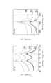
- Each electrode catalyst is an image observed by a transmission electron microscope, (A) is a Pt 1 Ru 1 / C, ( B) is a RuO 2 ns-Pt 1 Ru 1 / C, (C) is Runs -Pt 1 Ru 1 / C. Is an explanatory diagram showing a spectrum of binding energy relating Pt4f and Ru3d at each electrode catalyst, (a) is a Pt 1 Ru 1 / C, ( b) is a RuO 2 ns-Pt 1 Ru 1 / C, ( c) is Runs-Pt 1 Ru 1 / C.
- the electrode catalyst for a fuel cell and the production method thereof according to the present invention will be described in detail.
- the present invention is not limited to the following description as long as it is included in the technical scope.
- the fuel cell electrode catalyst according to the present invention is characterized in that it is a composite electrode catalyst comprising a ruthenium nanosheet and an electrode catalyst having ruthenium platinum alloy particles supported on carbon black.
- This composite electrode catalyst is preferably used as an anode electrode catalyst having hydrogen oxidation ability.
- the ruthenium nanosheet is a metal sheet having a huge specific surface area
- Ru atoms of the ruthenium nanosheet can be present in the vicinity of the Pt atoms on the surface of the ruthenium platinum alloy particles.
- Ru of the ruthenium nanosheet is poisoned with CO before Pt is poisoned with CO, so that the CO resistance of Pt can be increased.
- Ru ions are eluted from the ruthenium platinum alloy particles, it is expected that the eluted Ru ions are adsorbed on the ruthenium nanosheet and reprecipitated as Ru metal.
- the reprecipitated Ru metal contributes to CO poisoning, and it is possible to improve the catalyst deterioration suppressing ability with respect to the CO resistance of Pt.
- the ruthenium nanosheet is a metal nanosheet (also referred to as a metal nanosheet).
- the ruthenium nanosheet has a scaly shape with a thickness of about 1 nm, a planar direction is several ⁇ m in size, and has a huge specific surface area. Therefore, it can be used not only as an electrode catalyst but also as a thin film material or a coating agent.
- the fuel cell electrode catalyst preferably has a hydrogen oxidation reaction activity retention rate of 83% or more and a catalyst deterioration rate of 10% or less.
- the fuel cell electrode catalyst having such characteristics is preferably used as a CO resistant use and a catalyst deterioration suppressing use.
- the one where the upper limit of hydrogen oxidation reaction activity retention rate is larger is desirable, and it does not specifically limit.
- Pt 2 Ru 3 / C widely used is about 72%.
- the lower limit of the catalyst deterioration rate is desirably small, and is not particularly limited. In the Pt 2 Ru 3 / C, it is about 23%.
- the method for producing a fuel cell electrode catalyst according to the present invention is a method for producing the above-described fuel cell electrode catalyst according to the present invention. That is, this is a method for producing a composite electrode catalyst of a ruthenium nanosheet and an electrode catalyst having ruthenium platinum alloy particles supported on carbon black as an electrode catalyst for a fuel cell. Specifically, after the step of manufacturing a composite electrode catalyst of a RuO 2 nanosheet and an electrode catalyst supporting ruthenium platinum alloy particles on carbon black, and the step of manufacturing the composite electrode catalyst, the composite electrode catalyst is treated with hydrogen. And a step of baking and reducing in an atmosphere.
- the ruthenium oxide nanosheet (RuO 2 nanosheet) is obtained by peeling off a layer of ruthenium oxide prepared in advance, or between layers of ruthenium oxide (hydrogen type: H 0.2 RuO 2.1 ) as described in the examples below. It can be obtained by peeling off an alkylammonium-layered ruthenate intercalation compound containing alkylammonium ions.
- Ruthenium nanosheets can be obtained by reducing such ruthenium oxide nanosheets.
- a method for producing such a ruthenium nanosheet for example, a conventionally known method described in JP2010-280977A can be applied.
- the electrode catalyst in which ruthenium platinum alloy particles are supported on a carbon black support a conventionally known one described in, for example, Japanese Patent Application Laid-Open No. 2011-134477 can be applied.
- layered ruthenium oxide is a complex oxide of ruthenium oxide and an alkali metal (sodium, potassium, etc.).
- K 0.2 RuO 2.1 ⁇ nH 2 O and Na 0.2 RuO 2 ⁇ nH 2 O have ion exchange capacity. By using it, it is possible to delaminate the layer as a single unit, so that it was possible to obtain a ruthenium oxide nanosheet.
- ruthenium oxide (RuO 2 ) and potassium carbonate (K 2 CO 3 ) are weighed in a molar ratio of 8: 5 and wetted in acetone for 1 hour using an agate mortar. Mixed. Thereafter, the mixed powder was pelletized using a tablet molding machine. The pellets were placed on an alumina boat and baked at 850 ° C. for 12 hours in a tubular furnace under an argon atmosphere. After firing, the pellets were pulverized, washed with ion exchange distilled water, and the supernatant was removed. This operation was repeated until the supernatant became neutral to obtain layered ruthenium oxide (potassium type).
- RuO 2 ruthenium oxide
- K 2 CO 3 potassium carbonate
- layered ruthenium oxide (potassium type)
- acid treatment is performed in a water bath at 60 ° C. for 72 hours, so that K + ions contained in layered ruthenium oxide (potassium type) are converted into hydrogen ions (protons). ).
- the supernatant was removed by washing with ion-exchanged distilled water. This operation was repeated until the supernatant became neutral.
- layered ruthenium oxide hydrogen type: H 0.2 RuO 2.1
- layered ruthenium oxide (hydrogen type: H 0.2 RuO 2.1 )
- 10% TBAOH aqueous solution as a release agent for obtaining a ruthenium oxide nanosheet was added.
- layered ruthenium oxide (hydrogen type: H 0.2 RuO 2.1 ) was added to distilled water and shaken for 10 days.
- the ruthenium oxide nanosheet peeled off by this method was centrifuged at 2000 rpm for 30 minutes, and then the supernatant was collected and the aqueous dispersion of ruthenium oxide nanosheet diluted with ultrapure water to a concentration of 0.02 g / L ( Ruthenium oxide nanosheet colloid) was obtained.
- the ruthenium oxide nanosheet is described as RuO 2 ns.
- a test dispersion for a polymer electrolyte fuel cell was prepared by applying a catalyst dispersion to such glassy carbon. The catalyst dispersion was applied so that the carbon content was 5.5 ⁇ g / cm 2 regardless of the content of RuO 2 ns contained in the composite electrode catalyst provided on the test electrode.
- the nanosheets of RuO 2 ns-Pt 1 Ru 1 / C and Runs-Pt 1 Ru 1 / C partially covered the Pt 1 Ru 1 particles.
- the nanosheet of Runs-Pt 1 Ru 1 / C maintained the sheet form even after reduction.
- FIG. 2 is an explanatory diagram showing the spectrum of the binding energy related to Pt4f and Ru3d in each electrode catalyst, where (a) shows Pt 1 Ru 1 / C and (b) shows RuO 2 ns-Pt 1 Ru 1 / C. , (C) is Runs-Pt 1 Ru 1 / C.
- the Pt4f binding energy of Runs-Pt 1 Ru 1 / C was lower than Pt 1 Ru 1 / C and RuO 2 ns-Pt 1 Ru 1 / C. This is because the reduction of RuO 2 ns can predict that the Pt atom on the surface of the alloy particle and the Ru atom of Runs are metal-bonded, and therefore it is possible that the energy shift has occurred. This energy shift tendency is generally considered to be effective in improving CO tolerance.
- FIG. 3 is an explanatory view showing an X-ray diffraction pattern of each electrocatalyst, wherein (a) is Pt 2 Ru 3 / C, (b) is Pt 1 Ru 1 / C, and (c) is RuO. 2 ns-Pt 1 Ru 1 / C, and (d) is Runs-Pt 1 Ru 1 / C.
- the amount of hydrogen desorption electricity of Runs-Pt 1 Ru 1 / C is about three times larger than Pt 1 Ru 1 / C and RuO 2 ns-Pt 1 Ru 1 / C. This increase in the amount of electricity desorbed from hydrogen is thought to be due to the formation of ruthenium nanosheets.
- the composite electrode catalyst composed of ruthenium nanosheets has improved CO resistance.
- Runs-Pt 1 Ru 1 / C The hydrogen oxidation reaction activity of Runs-Pt 1 Ru 1 / C after the endurance test was repeated 5000 cycles under the same conditions was 93A (g-PtRu) ⁇ 1 . This was higher than Pt 2 Ru 3 / C and Pt 1 Ru 1 / C after 1000 cycles endurance test, and was similar to RuO 2 ns-Pt 1 Ru 1 / C after 1000 cycles endurance test. From this, it is understood that Runs-Pt 1 Ru 1 / C has high catalyst durability, and can be expected to be an electrode catalyst that can be operated for a long time.
- Ru ions eluted in the durability test may have re-deposited as Ru metal on the nanosheet, which is considered to improve the catalyst durability.
- the improvement in CO tolerance of the composite electrocatalyst of Runs and Pt 1 Ru 1 / C is considered to be due to the ligand effect accompanying the change in the electronic state of Pt. As a result, it is expected that CO molecules adsorbed on Pt are easily oxidized and removed. In addition, there is a possibility that CO is first adsorbed to the Ru atoms of Runs before CO adsorption to Pt with the conversion to Runs, and this point is also considered to contribute to the improvement of CO resistance.
Landscapes
- Chemical & Material Sciences (AREA)
- Chemical Kinetics & Catalysis (AREA)
- Electrochemistry (AREA)
- General Chemical & Material Sciences (AREA)
- Engineering & Computer Science (AREA)
- Materials Engineering (AREA)
- Manufacturing & Machinery (AREA)
- Inert Electrodes (AREA)
- Catalysts (AREA)
Abstract
【課題】家庭用の固体高分子形燃料電池に用いられる電極触媒として好ましく用いられ、CO耐性能及び触媒劣化抑制能をより向上させることができる燃料電池用電極触媒及びその製造方法を提供する。 【解決手段】ルテニウムナノシートとカーボンブラック上にルテニウム白金合金粒子を担持した電極触媒との複合電極触媒である燃料電池用電極触媒により上記課題を解決した。この燃料電池用電極触媒は、水素酸化能を有するアノード電極触媒であることが好ましく、水素酸化反応活性保持率が83%以上で、触媒劣化率が10%以下であることが好ましく、CO耐性用途及び触媒劣化抑制用途の電極触媒として好ましく用いられる。
Description
本発明は、燃料電池用電極触媒及びその製造方法に関し、さらに詳しくは、固体高分子形燃料電池用の電極触媒として好ましく用いられ、CO耐性能及び触媒劣化抑制能をより向上させることができる燃料電池用の電極触媒及びその製造方法に関する。
家庭用の固体高分子形燃料電池システムは、改質器をより高性能にする方向で開発が進められており、高コスト化の傾向になっている。これを低コスト化させるには、安価な燃料ガスを用いることが望ましく、例えば500ppmのCOとH2の混合ガスを燃料ガスとして用いることが好ましい。しかし、こうした燃料ガスは、一般的な燃料ガスに比べてCO濃度が50倍程度高く、そのため、家庭用の固体高分子形燃料電池システムを構成する燃料電池の電極触媒には、高いCO耐性が求められている。
高いCO耐性の電極触媒として、ルテニウム白金合金粒子が広く用いられている。そのルテニウム白金合金粒子は、ルテニウムと白金との合金化によりPt電子状態が変化することから、リガンド効果又は二元機能機構に起因した高CO耐性の電極触媒になることが知られている。
近年、高いCO耐性を有する電池触媒として、カーボンブラック担体上にルテニウム白金合金粒子(Ru/Pt=3/2(モル比))を担持したPt2Ru3/C触媒や、ルテニウムと白金のモル比がRu/Pt=1/1であるPt1Ru1/C触媒が知られており、その金属原子の組成比やPtの電子状態について検討されている(非特許文献1)。
しかしながら、上記Pt2Ru3/C触媒やPt1Ru1/C触媒は、Pt原子とRu原子とが粒子内で偏在しているため、CO耐性を効果的に高めることが困難であった。
この課題に対して、Pt原子とRu原子とを合金粒子内で100%混在させることにより、CO耐性が飛躍的に高まることが報告されている(非特許文献2)。なお、この電極触媒は、Pt原子とRu原子との合金粒子を合成するために高温で焼成した後、急冷させることで得られている。
H.Yamada,D.Shimoda,K.Matsuzawa,A.Tasaka,andM.Inaba,ECSTrans.,11(1),325(2007).
T.Takeguchi,T.Yamanaka,K.Asakura,E.N.Muhamad,K.Uosaki,andW.Ueda,J.Am.Chem.Soc.,134(35),14508(2012).
家庭用の固体高分子形燃料電池に用いる電極触媒には、CO耐性の向上だけでなく、電極触媒能が劣化しにくい特性を持たせることも重要な課題である。その電極触媒能の劣化は、燃料電池の起動時や停止時に起こる電圧負荷によりルテニウム白金合金粒子からRuイオンが溶出してしまい、結果としてCO耐性が低下することとして知られている。
本発明は、上記課題を解決するためになされたものであって、その目的は、家庭用の固体高分子形燃料電池に用いられる電極触媒として好ましく用いられ、CO耐性能及び触媒劣化抑制能をより向上させることができる燃料電池用電極触媒及びその製造方法を提供することにある。
本発明者は、CO耐性をより向上させるため、Pt原子近傍にRu原子が存在する電極触媒について研究するとともに、触媒劣化抑制能をより向上させるため、Ruイオン溶出を抑制できる電極触媒についても研究した。本発明者は、その研究を進めている過程で、Pt原子にCOが吸着する前に、Ru原子にCOを吸着させることができれば、CO耐性をより向上させることができるのではないかと考え、巨大な比表面積を有するRuシートの使用を検討した。
上記課題を解決するための本発明に係る燃料電池用電極触媒は、ルテニウムナノシートとカーボンブラック上にルテニウム白金合金粒子を担持した電極触媒との複合電極触媒であることを特徴とする。
この発明によれば、ルテニウムナノシートは、巨大な比表面積を有するメタルシートであるので、ルテニウム白金合金粒子表面のPt原子近傍にルテニウムナノシートのRu原子を存在させることができる。これにより、PtがCO被毒する前にルテニウムナノシートのRuがCO被毒するので、PtのCO耐性を高めることができる。また、ルテニウム白金合金粒子からRuイオンが溶出した場合であっても、溶出したRuイオンはルテニウムナノシート上に吸着してRu金属として再析出することが予想される。その結果、再析出したRu金属がCO被毒に寄与することになり、PtのCO耐性についての触媒劣化抑制能を高めることができる。
本発明に係る燃料電池用電極触媒において、前記複合電極触媒が、水素酸化能を有するアノード電極触媒であることが好ましい。
本発明に係る燃料電池用電極触媒において、水素酸化反応活性保持率が83%以上で、触媒劣化率が10%以下であることが好ましい。
本発明に係る燃料電池用電極触媒において、CO耐性用途及び触媒劣化抑制用途に用いられることが好ましい。
上記課題を解決するための本発明に係る燃料電池用電極触媒の製造方法は、ルテニウムナノシートとカーボンブラック上にルテニウム白金合金粒子を担持した電極触媒との複合電極触媒を燃料電池用電極触媒として製造する方法であって、RuO2ナノシートとカーボンブラック上にルテニウム白金合金粒子を担持した電極触媒との複合電極触媒を製造する工程と、前記複合電極触媒を製造する工程の後、該複合電極触媒を水素雰囲気下で焼成して還元する工程とを有することを特徴とする。なお、RuO2ナノシートは、予め作製した層状酸化ルテニウムを単層剥離して得ることができる。
本発明に係る燃料電池用電極触媒によれば、家庭用の固体高分子形燃料電池に用いられる電極触媒として、特に水素酸化能を有するアノード電極触媒として好ましく用いられ、CO耐性能及び触媒劣化抑制能をより向上させることができる。
以下、本発明に係る燃料電池用電極触媒及びその製造方法について詳しく説明する。本発明は、その技術的範囲に含まれる範囲において下記の説明に限定されない。
[燃料電池用電極触媒]
本発明に係る燃料電池用電極触媒は、ルテニウムナノシートとカーボンブラック上にルテニウム白金合金粒子を担持した電極触媒との複合電極触媒であることに特徴がある。この複合電極触媒は、水素酸化能を有するアノード電極触媒として好ましく用いられる。
本発明に係る燃料電池用電極触媒は、ルテニウムナノシートとカーボンブラック上にルテニウム白金合金粒子を担持した電極触媒との複合電極触媒であることに特徴がある。この複合電極触媒は、水素酸化能を有するアノード電極触媒として好ましく用いられる。
この複合電極触媒は、ルテニウムナノシートが巨大な比表面積を有するメタルシートであるので、ルテニウム白金合金粒子表面のPt原子近傍にルテニウムナノシートのRu原子を存在させることができる。これにより、PtがCO被毒する前にルテニウムナノシートのRuがCO被毒するので、PtのCO耐性を高めることができる。また、ルテニウム白金合金粒子からRuイオンが溶出した場合であっても、溶出したRuイオンはルテニウムナノシート上に吸着してRu金属として再析出することが予想される。その結果、再析出したRu金属がCO被毒に寄与することになり、PtのCO耐性についての触媒劣化抑制能を高めることができる。
ルテニウムナノシートは、金属ナノシート(メタルナノシートともいう。)である。ルテニウムナノシートは、厚さ約1nmの鱗片形状であり、平面方向が数μmサイズであり、巨大な比表面積を有している。そのため、電極触媒としての利用のほか、薄膜材料やコーティング剤としても利用できる。
燃料電池用電極触媒は、水素酸化反応活性保持率が83%以上で、触媒劣化率が10%以下であることが好ましい。こうした特性を有する燃料電池用電極触媒は、CO耐性用途及び触媒劣化抑制用途として好ましく用いられる。
なお、水素酸化反応活性保持率の上限は大きい方が望ましく、特に限定されない。なお、広く使用されているPt2Ru3/Cでは72%程度である。また、触媒劣化率の下限は小さい方が望ましく、特に限定されない。なお、前記Pt2Ru3/Cでは、23%程度である。
[製造方法]
本発明に係る燃料電池用電極触媒の製造方法は、上記した本発明に係る燃料電池用電極触媒を製造する方法である。すなわち、ルテニウムナノシートとカーボンブラック上にルテニウム白金合金粒子を担持した電極触媒との複合電極触媒を燃料電池用電極触媒として製造する方法である。具体的には、RuO2ナノシートとカーボンブラック上にルテニウム白金合金粒子を担持した電極触媒との複合電極触媒を製造する工程と、その複合電極触媒を製造する工程の後、該複合電極触媒を水素雰囲気下で焼成して還元する工程とを有する方法である。
本発明に係る燃料電池用電極触媒の製造方法は、上記した本発明に係る燃料電池用電極触媒を製造する方法である。すなわち、ルテニウムナノシートとカーボンブラック上にルテニウム白金合金粒子を担持した電極触媒との複合電極触媒を燃料電池用電極触媒として製造する方法である。具体的には、RuO2ナノシートとカーボンブラック上にルテニウム白金合金粒子を担持した電極触媒との複合電極触媒を製造する工程と、その複合電極触媒を製造する工程の後、該複合電極触媒を水素雰囲気下で焼成して還元する工程とを有する方法である。
酸化ルテニウムナノシート(RuO2ナノシート)は、予め作製した層状酸化ルテニウムを単層剥離したり、また、後述の実施例で説明するように、層状酸化ルテニウム(水素型:H0.2RuO2.1)の層間にアルキルアンモニウムイオンを含むアルキルアンモニウム-層状ルテニウム酸層間化合物を剥離したりして得ることができる。
ルテニウムナノシートは、そうした酸化ルテニウムナノシートを還元して得ることができる。こうしたルテニウムナノシートの製造方法は、例えば特開2010-280977号公報に記載の従来公知のものを適用できる。
また、カーボンブラック担体上にルテニウム白金合金粒子が担持した電極触媒は、例えば特開2011-134477号公報に記載の従来公知のものを適用できる。
以下、実験例により本発明を具体的に説明する。以下の実験では、酸化ルテニウムナノシートとPt1Ru1/Cとの複合電極触媒を、現在広く使用されているPt2Ru3/CについてのRuとPtのモル比と同様になるように製造した。その後、その複合電極触媒を水素雰囲気下で焼成して還元することにより、ルテニウムナノシートとPt1Ru1/Cとの複合電極触媒を作製した。このとき、酸化ルテニウムナノシートからルテニウムナノシートへの還元が、触媒性能にどのような影響を与えるかを検討した。
[酸化ルテニウムナノシートの製造]
初めに、酸化ルテニウムナノシートを得るために、層状酸化ルテニウムを作製した。層状酸化ルテニウムは、酸化ルテニウムとアルカリ金属(ナトリウム、カリウム等)との複合酸化物であり、中でも、K0.2RuO2.1・nH2O、及びNa0.2RuO2・nH2Oは、イオン交換能を利用することで層一枚単位にまで層剥離することが可能であるので、これにより酸化ルテニウムナノシートを得ることができた。
初めに、酸化ルテニウムナノシートを得るために、層状酸化ルテニウムを作製した。層状酸化ルテニウムは、酸化ルテニウムとアルカリ金属(ナトリウム、カリウム等)との複合酸化物であり、中でも、K0.2RuO2.1・nH2O、及びNa0.2RuO2・nH2Oは、イオン交換能を利用することで層一枚単位にまで層剥離することが可能であるので、これにより酸化ルテニウムナノシートを得ることができた。
具体的には、先ず、酸化ルテニウム(RuO2)と炭酸カリウム(K2CO3)とをモル比8:5の割合となるように秤り取り、メノウ乳鉢を用いてアセトン中で1時間湿式混合した。その後、錠剤成形器を用いて混合粉末をペレット化した。このペレットをアルミナボートに載せ、管状炉にてアルゴン雰囲気下で850℃、12時間焼成した。焼成後、ペレットを粉砕し、イオン交換蒸留水で洗浄し、上澄み液を取り除いた。この操作を上澄み液が中性になるまで繰り返し、層状酸化ルテニウム(カリウム型)を得た。
次に、層状酸化ルテニウム(カリウム型)に1MのHClを加え、60℃のウォーターバス内で72時間酸処理をして、層状酸化ルテニウム(カリウム型)に含まれるK+イオンを水素イオン(プロトン)に置換した。その後、イオン交換蒸留水で洗浄し上澄み液を取り除いた。この操作を上澄み液が中性になるまで繰り返し、ろ過後に、層状酸化ルテニウム(水素型:H0.2RuO2.1)の粉末を得た。
得られた層状酸化ルテニウム(水素型:H0.2RuO2.1)に、酸化ルテニウムナノシートを得る剥離剤としての10%TBAOH水溶液を加えた。層状酸化ルテニウム(水素型:H0.2RuO2.1)の濃度を、TBAOHとプロトンとの割合でTBA+/H+=1.5、固液比=4g/Lとした。そして、層状酸化ルテニウム(水素型:H0.2RuO2.1)を蒸留水に加え、10日間振とうさせた。この方法で単層剥離させた酸化ルテニウムナノシートを2000rpmで30分間遠心分離した後、上澄み液を回収して、超純水にて濃度を0.02g/Lまで希釈した酸化ルテニウムナノシート水分散液(酸化ルテニウムナノシートコロイド)を得た。なお、以下では、酸化ルテニウムナノシートをRuO2nsと記述する。
[実験1/RuO2ns-Pt1Ru1/Cの作製]
先ず、RuO2nsをPt1Ru1/Cと組み合わせるために、10mg/mLとなるようにPt1Ru1/Cを超純水15mL中に加え、撹拌30分間及び超音波処理30分間を行って分散させた。この溶液に、上記したPt1Ru1/CのPtとRuのモル比(Pt:Ru)が、1:1.5になるように適量のRuO2nsコロイドを、撹拌しながらゆっくり滴下した。RuO2nsコロイドの濃度は任意に調整できるが、ここでは10mg/mLとした。
先ず、RuO2nsをPt1Ru1/Cと組み合わせるために、10mg/mLとなるようにPt1Ru1/Cを超純水15mL中に加え、撹拌30分間及び超音波処理30分間を行って分散させた。この溶液に、上記したPt1Ru1/CのPtとRuのモル比(Pt:Ru)が、1:1.5になるように適量のRuO2nsコロイドを、撹拌しながらゆっくり滴下した。RuO2nsコロイドの濃度は任意に調整できるが、ここでは10mg/mLとした。
さらに、均一な反応を確保するために、撹拌、超音波処理、60℃で静置、デカンテーション(中性になるまで水洗浄)を順に行った後、120℃で12時間乾燥させ、その後に粉砕して、RuO2ns-Pt1Ru1/Cを得た。
[実験2/Runs-Pt1Ru1/Cの作製]
得られたRuO2ns-Pt1Ru1/Cをアルミナボートに載せ、管状炉にて水素と窒素の混合雰囲気下で120℃、2時間焼成した。水素流量は10cc/minで、窒素流量は150cc/minで、これらのガスを混合して管状炉へ流した。焼成後に粉砕して、Runs-Pt1Ru1/Cを得た。なお、以下では、ルテニウムナノシートをRunsと記述する。
得られたRuO2ns-Pt1Ru1/Cをアルミナボートに載せ、管状炉にて水素と窒素の混合雰囲気下で120℃、2時間焼成した。水素流量は10cc/minで、窒素流量は150cc/minで、これらのガスを混合して管状炉へ流した。焼成後に粉砕して、Runs-Pt1Ru1/Cを得た。なお、以下では、ルテニウムナノシートをRunsと記述する。
[実験3/触媒分散液及び試験電極の準備]
2-プロパノール/超純水溶液(75/25体積割合)25mLに、上記実験1,2で得られた複合電極触媒18.5mgを混合して、触媒分散液を準備した。試験電極に対して良好な密着性を確保するために、プロトン伝導性バインダーとして、5質量%のナフィオン(Nafion、デュポン社の登録商標)溶液100μLを加えた。この触媒分散液を30分間超音波処理して分散させた。
2-プロパノール/超純水溶液(75/25体積割合)25mLに、上記実験1,2で得られた複合電極触媒18.5mgを混合して、触媒分散液を準備した。試験電極に対して良好な密着性を確保するために、プロトン伝導性バインダーとして、5質量%のナフィオン(Nafion、デュポン社の登録商標)溶液100μLを加えた。この触媒分散液を30分間超音波処理して分散させた。
予め0.05μmのアルミナ粉末を用いてバフ研磨した直径6mmのグラッシーカーボンを、真空中で60℃で乾燥させた。こうしたグラッシーカーボンに触媒分散液を塗布して固体高分子形燃料電池用の試験電極を作製した。なお、触媒分散液の塗布は、試験電極上に設けられた複合電極触媒に含まれるRuO2nsの含有量に関わらず、カーボン含有量が5.5μg/cm2となるように塗布した。
[実験4/電気化学的測定]
回転ディスク電極(RDE)測定は、標準的な三電極電気化学セルで行った。カウンター電極として、炭素繊維(TohoTenax社製、HTA-3K、フィラメント番号:3000)を用い、参照電極として可逆水素電極(RHE)を用いた。RDE測定は、0.1MのHClO4電解液中で行った。
回転ディスク電極(RDE)測定は、標準的な三電極電気化学セルで行った。カウンター電極として、炭素繊維(TohoTenax社製、HTA-3K、フィラメント番号:3000)を用い、参照電極として可逆水素電極(RHE)を用いた。RDE測定は、0.1MのHClO4電解液中で行った。
[実験結果]
(触媒形態の評価)
各電極触媒の触媒形態を、透過型電子顕微鏡により観察し、図1にその画像を示した。図1(A)はPt1Ru1/Cであり、図1(B)はRuO2ns-Pt1Ru1/Cであり、図1(C)はRuns-Pt1Ru1/Cである。
(触媒形態の評価)
各電極触媒の触媒形態を、透過型電子顕微鏡により観察し、図1にその画像を示した。図1(A)はPt1Ru1/Cであり、図1(B)はRuO2ns-Pt1Ru1/Cであり、図1(C)はRuns-Pt1Ru1/Cである。
図1に示すように、RuO2ns-Pt1Ru1/C、及び、Runs-Pt1Ru1/Cのナノシートは、Pt1Ru1粒子を部分的に覆っていた。また、Runs-Pt1Ru1/Cのナノシートは、還元した後でも、シート形態を維持していた。
(Pt4f及びRu3dに関する結合エネルギーの評価)
各電極触媒のPt4f及びRu3dに関する結合エネルギーを、X線光電子分光法により比較した。図2は、各電極触媒におけるPt4f及びRu3dに関する結合エネルギーのスペクトルを示す説明図であり、(a)はPt1Ru1/Cを、(b)はRuO2ns-Pt1Ru1/Cを、(c)はRuns-Pt1Ru1/Cである。
各電極触媒のPt4f及びRu3dに関する結合エネルギーを、X線光電子分光法により比較した。図2は、各電極触媒におけるPt4f及びRu3dに関する結合エネルギーのスペクトルを示す説明図であり、(a)はPt1Ru1/Cを、(b)はRuO2ns-Pt1Ru1/Cを、(c)はRuns-Pt1Ru1/Cである。
図2に示すように、Runs-Pt1Ru1/CのPt4f結合エネルギーは、Pt1Ru1/C及びRuO2ns-Pt1Ru1/Cよりも低かった。これは、RuO2nsの還元により、合金粒子表面のPt原子とRunsのRu原子が金属結合したことが予想でき、それ故、エネルギーシフトした可能性が考えられる。このエネルギーシフトの傾向は、一般的に、CO耐性の向上に効果があると考えられる。
(各電極触媒のX線回折パターンによるPt構造解析の評価)
各電極触媒のPt構造を、X線回折パターンにより比較した。図3は、各電極触媒のX線回折パターンを示す説明図であり、(a)はPt2Ru3/Cであり、(b)はPt1Ru1/Cであり、(c)はRuO2ns-Pt1Ru1/Cであり、(d)はRuns-Pt1Ru1/Cである。
各電極触媒のPt構造を、X線回折パターンにより比較した。図3は、各電極触媒のX線回折パターンを示す説明図であり、(a)はPt2Ru3/Cであり、(b)はPt1Ru1/Cであり、(c)はRuO2ns-Pt1Ru1/Cであり、(d)はRuns-Pt1Ru1/Cである。
図3より、Pt2Ru3/Cのd=0.21nm付近(2θ=43.7°)で、hcp構造であるPt-Ruのピークを確認できた。一方、Pt1Ru1/C及びRuO2ns-Pt1Ru1/C、Runs-Pt1Ru1/Cでは、このピークを確認できなかった。このことから、Pt1Ru1/C及びRuO2ns-Pt1Ru1/C、Runs-Pt1Ru1/Cは、Pt2Ru3/Cよりも触媒の耐久性が高いと考えられる。
(水素吸脱着量の評価)
各電極触媒の水素脱離領域における電気量を、PtRu量で割付けたサイクリックボルタモグラムから算出し比較した。図4は、各電極触媒のPtRu量で割付けたサイクリックボルタモグラムである。表1は、各電極触媒の水素脱離領域から算出した電気量である。
各電極触媒の水素脱離領域における電気量を、PtRu量で割付けたサイクリックボルタモグラムから算出し比較した。図4は、各電極触媒のPtRu量で割付けたサイクリックボルタモグラムである。表1は、各電極触媒の水素脱離領域から算出した電気量である。
図4及び表1より、Runs-Pt1Ru1/Cの水素脱離電気量は、Pt1Ru1/C及びRuO2ns-Pt1Ru1/Cより約3倍も大きい。この水素脱離電気量の増加は、ルテニウムナノシート化に起因していると考えられる。
合金粒子表面のPt原子と近傍にRu原子が存在できる確率が高くなる、かつPt原子だけでなく、巨大な比表面積を有するルテニウムナノシートへもCO吸着されると考えられるため、CO耐性の向上が期待できる。

(CO耐性の評価)
各電極触媒の20mV(vs.RHE)におけるCO耐性を、300ppmCO/H2飽和下の60分後の水素酸化反応活性を比較することで評価した。300ppmCO/H2飽和下の0.1MHClO4電解液(25℃)を使用し、20mV(vs.RHE)で60分間保持したクロノアンペロメトリーを行った。表2は、各電極触媒の耐久試験前における300ppmCO/H2飽和下の0分と60分後の水素酸化反応活性、及び、触媒活性保持率を示した。
各電極触媒の20mV(vs.RHE)におけるCO耐性を、300ppmCO/H2飽和下の60分後の水素酸化反応活性を比較することで評価した。300ppmCO/H2飽和下の0.1MHClO4電解液(25℃)を使用し、20mV(vs.RHE)で60分間保持したクロノアンペロメトリーを行った。表2は、各電極触媒の耐久試験前における300ppmCO/H2飽和下の0分と60分後の水素酸化反応活性、及び、触媒活性保持率を示した。
表2より、60分後のRuns-Pt1Ru1/Cの300ppmCO/H2飽和下での水素酸化反応活性は、125A(g-PtRu)-1であり、Pt1Ru1/Cの25%増、RuO2ns-Pt1Ru1/Cの7%増であった。また、広く使用されている標準性能のPt2Ru3/Cより21%も高かった。
また、表2より、Runs-Pt1Ru1/Cの水素酸化反応活性は、17%しかCO被毒されなかった。これは、Runs-Pt1Ru1/Cが高いCO耐性であることを示している。
電解液中のCOは、Ptだけでなくルテニウムナノシートにも吸着できるため、CO被毒量を抑制できることが期待できる。それ故、ルテニウムナノシートで構成される複合電極触媒は、CO耐性が向上したと考えられる。

(触媒耐久性の評価)
各電極触媒の耐久性を評価するために、0.05~0.4V(vs.RHE)の電位範囲を100mVs-1で走査し、1000サイクルの耐久試験を行った。各電極触媒の耐久性は、加速耐久試験前後の20mV(vs.RHE)における300ppmCO/H2飽和下での60分後の水素酸化反応活性を比較することで評価した。表3は、各電極触媒の耐久試験前後における300ppmCO/H2飽和下の60分後の水素酸化反応活性、及び、触媒劣化率を示した。
各電極触媒の耐久性を評価するために、0.05~0.4V(vs.RHE)の電位範囲を100mVs-1で走査し、1000サイクルの耐久試験を行った。各電極触媒の耐久性は、加速耐久試験前後の20mV(vs.RHE)における300ppmCO/H2飽和下での60分後の水素酸化反応活性を比較することで評価した。表3は、各電極触媒の耐久試験前後における300ppmCO/H2飽和下の60分後の水素酸化反応活性、及び、触媒劣化率を示した。
表3より、Pt2Ru3/CとPt1Ru1/C、RuO2ns-Pt1Ru1/Cは、耐久試験で20%程度も劣化した。一方、Runs-Pt1Ru1/Cの劣化率は10%であり、触媒耐久性が向上した。このことから、ルテニウムナノシート化により、CO耐性と触媒耐久性の両方を高められることがわかった。
また、耐久試験を同条件下で5000サイクル行った後のRuns-Pt1Ru1/Cの水素酸化反応活性は、93A(g-PtRu)-1であった。これは、1000サイクルの耐久試験後のPt2Ru3/CとPt1Ru1/Cよりも高く、1000サイクルの耐久試験後のRuO2ns-Pt1Ru1/Cと同様であった。このことから、Runs-Pt1Ru1/Cは、触媒耐久性が高いことがわかり、長時間作動を実現できる電極触媒であると予想できる。
ルテニウムナノシートの高い導電性により、耐久試験で溶出したRuイオンが、ナノシート上でRuメタルとして再析出した可能性があり、これにより触媒耐久性が向上したと考えられる。

以上の実験結果より、RuO2ns-Pt1Ru1/CのCO耐性は、Pt2Ru3/Cと同等であったが、Pt1Ru1/Cよりも高かった。また、RuO2ns-Pt1Ru1/Cの触媒耐久性は、Pt1Ru1/C及びPt2Ru3/Cよりも高かった。
Runs-Pt1Ru1/CのCO耐性と触媒耐久性は、RuO2ns-Pt1Ru1/CやPt1Ru1/C、Pt2Ru3/Cよりも高かった。
上記結果をまとめると、RunsとPt1Ru1/Cとの複合電極触媒は、CO耐性及び触媒耐久性を高められることがわかった。
RuO2nsとPt1Ru1/Cとの複合電極触媒は、50mV(vs.RHE)でCOをわずかに酸化できることがわかっている。このことから、RuO2nsとPt1Ru1/Cとの複合電極触媒のCO耐性向上は、わずかなCO酸化活性の向上に起因していると予想される。
RunsとPt1Ru1/Cとの複合電極触媒のCO耐性向上は、Ptの電子状態変化に伴うリガンド効果に起因すると考えられる。これにより、Ptに吸着したCO分子が酸化除去され易くなったと予想している。また、Runs化に伴いPtへのCO吸着前にRunsのRu原子へCOが先に吸着した可能性もあり、この点もCO耐性向上に寄与していると考えられる。
RuO2ns又はRunsとPt1Ru1/Cとの複合電極触媒で触媒耐久性が向上した要因は、耐久試験で溶出したRuイオンがナノシート上に吸着し、Ru金属として再析出したためであると予想される。
Claims (5)
- ルテニウムナノシートとカーボンブラック上にルテニウム白金合金粒子を担持した電極触媒との複合電極触媒であることを特徴とする燃料電池用電極触媒。
- 前記複合電極触媒が、水素酸化能を有するアノード電極触媒である、請求項1に記載の燃料電池用電極触媒。
- 水素酸化反応活性保持率が83%以上で、触媒劣化率が10%以下である、請求項1又は2に記載の燃料電池用電極触媒。
- CO耐性用途及び触媒劣化抑制用途に用いられる、請求項1~3のいずれか1項に記載の燃料電池用電極触媒。
- ルテニウムナノシートとカーボンブラック上にルテニウム白金合金粒子を担持した電極触媒との複合電極触媒を燃料電池用電極触媒として製造する方法であって、
RuO2ナノシートとカーボンブラック上にルテニウム白金合金粒子を担持した電極触媒との複合電極触媒を製造する工程と、
前記複合電極触媒を製造する工程の後、該複合電極触媒を水素雰囲気下で焼成して還元する工程とを有することを特徴とする燃料電池用電極触媒の製造方法。
Priority Applications (1)
| Application Number | Priority Date | Filing Date | Title |
|---|---|---|---|
| PCT/JP2014/084654 WO2016103494A1 (ja) | 2014-12-26 | 2014-12-26 | 燃料電池用電極触媒及びその製造方法 |
Applications Claiming Priority (1)
| Application Number | Priority Date | Filing Date | Title |
|---|---|---|---|
| PCT/JP2014/084654 WO2016103494A1 (ja) | 2014-12-26 | 2014-12-26 | 燃料電池用電極触媒及びその製造方法 |
Publications (1)
| Publication Number | Publication Date |
|---|---|
| WO2016103494A1 true WO2016103494A1 (ja) | 2016-06-30 |
Family
ID=56149577
Family Applications (1)
| Application Number | Title | Priority Date | Filing Date |
|---|---|---|---|
| PCT/JP2014/084654 Ceased WO2016103494A1 (ja) | 2014-12-26 | 2014-12-26 | 燃料電池用電極触媒及びその製造方法 |
Country Status (1)
| Country | Link |
|---|---|
| WO (1) | WO2016103494A1 (ja) |
Citations (4)
| Publication number | Priority date | Publication date | Assignee | Title |
|---|---|---|---|---|
| WO2007046279A1 (ja) * | 2005-10-19 | 2007-04-26 | Shin-Etsu Chemical Co., Ltd. | 燃料電池用電極触媒 |
| JP2010280977A (ja) * | 2009-06-08 | 2010-12-16 | Shinshu Univ | 金属ナノシートの製造方法、および金属ナノシート |
| JP2011134477A (ja) * | 2009-12-22 | 2011-07-07 | Shinshu Univ | 燃料電池用電極触媒の製造方法 |
| JP2011253627A (ja) * | 2010-05-31 | 2011-12-15 | National Institute For Materials Science | 燃料電池用電極触媒およびその製造方法 |
-
2014
- 2014-12-26 WO PCT/JP2014/084654 patent/WO2016103494A1/ja not_active Ceased
Patent Citations (4)
| Publication number | Priority date | Publication date | Assignee | Title |
|---|---|---|---|---|
| WO2007046279A1 (ja) * | 2005-10-19 | 2007-04-26 | Shin-Etsu Chemical Co., Ltd. | 燃料電池用電極触媒 |
| JP2010280977A (ja) * | 2009-06-08 | 2010-12-16 | Shinshu Univ | 金属ナノシートの製造方法、および金属ナノシート |
| JP2011134477A (ja) * | 2009-12-22 | 2011-07-07 | Shinshu Univ | 燃料電池用電極触媒の製造方法 |
| JP2011253627A (ja) * | 2010-05-31 | 2011-12-15 | National Institute For Materials Science | 燃料電池用電極触媒およびその製造方法 |
Similar Documents
| Publication | Publication Date | Title |
|---|---|---|
| Kim et al. | Effect of surface oxygen functionalization of carbon support on the activity and durability of Pt/C catalysts for the oxygen reduction reaction | |
| Huang et al. | Development of supported bifunctional oxygen electrocatalysts and corrosion-resistant gas diffusion layer for unitized regenerative fuel cell applications | |
| Elezovic et al. | Platinum nanocatalysts on metal oxide based supports for low temperature fuel cell applications | |
| US10985382B2 (en) | Core-shell structure type nanosheet | |
| Zhang et al. | Highly stable ternary tin–palladium–platinum catalysts supported on hydrogenated TiO 2 nanotube arrays for fuel cells | |
| US20060194097A1 (en) | Nano-structured metal-carbon composite for electrode catalyst of fuel cell and process for preparation thereof | |
| Pătru et al. | Pt/IrO2–TiO2 cathode catalyst for low temperature polymer electrolyte fuel cell–Application in MEAs, performance and stability issues | |
| Zhou et al. | Solving Nafion poisoning of ORR catalysts with an accessible layer: designing a nanostructured core‐shell Pt/C catalyst via a one‐step self‐assembly for PEMFC | |
| Fuentes et al. | Pt-Ir/TiC electrocatalysts for PEM fuel cell/electrolyzer process | |
| KR102291160B1 (ko) | 연료전지용 금 도핑 백금계 합금 촉매 및 이의 제조 방법 | |
| JP5792567B2 (ja) | 酸素還元能を有する電極触媒 | |
| CN105409042A (zh) | 催化剂 | |
| CN112585788B (zh) | 固体高分子型燃料电池用催化剂和固体高分子型燃料电池用催化剂的选定方法 | |
| Sebastián et al. | Influence of metal oxide additives on the activity and stability of PtRu/C for methanol electro-oxidation | |
| Kwak et al. | Investigation of the durability of Fe/N-doped mesoporous carbon nanostructure as a non-precious metal catalyst for oxygen reduction reaction in acid medium | |
| JP2016091878A (ja) | 電極材料の製造方法、膜電極接合体および燃料電池スタック | |
| JP5669432B2 (ja) | 膜電極接合体、燃料電池および燃料電池の活性化方法 | |
| Cao et al. | Oxygen-modified supra-nanometer-sized RuPt for robust alkaline HER/HOR | |
| JP2018029011A (ja) | 酸素還元触媒、その製造方法および燃料電池 | |
| CN111342068B (zh) | 夹层式催化剂及其制备方法和应用 | |
| Kim et al. | A facile approach to improve the performance of alkaline anion exchange membrane fuel cells by reducing ionic resistance | |
| JP6734345B2 (ja) | 燃料電池の陽極のための金属合金触媒 | |
| Li et al. | High-temperature annealing improves Pt utilization of proton exchange membrane fuel cell cathode catalysts | |
| JP6159283B2 (ja) | 燃料電池用電極触媒 | |
| Gao et al. | Synthesis of carbon microspheres loaded with manganese oxide as air cathode in alkaline media |
Legal Events
| Date | Code | Title | Description |
|---|---|---|---|
| 121 | Ep: the epo has been informed by wipo that ep was designated in this application |
Ref document number: 14909096 Country of ref document: EP Kind code of ref document: A1 |
|
| NENP | Non-entry into the national phase |
Ref country code: DE |
|
| 122 | Ep: pct application non-entry in european phase |
Ref document number: 14909096 Country of ref document: EP Kind code of ref document: A1 |
|
| NENP | Non-entry into the national phase |
Ref country code: JP |