WO2016103345A1 - 充電端子の保護機構、及びこの保護機構を備えた充電スタンド - Google Patents
充電端子の保護機構、及びこの保護機構を備えた充電スタンド Download PDFInfo
- Publication number
- WO2016103345A1 WO2016103345A1 PCT/JP2014/084065 JP2014084065W WO2016103345A1 WO 2016103345 A1 WO2016103345 A1 WO 2016103345A1 JP 2014084065 W JP2014084065 W JP 2014084065W WO 2016103345 A1 WO2016103345 A1 WO 2016103345A1
- Authority
- WO
- WIPO (PCT)
- Prior art keywords
- charging
- terminal
- pair
- terminals
- electronic terminal
- Prior art date
- Legal status (The legal status is an assumption and is not a legal conclusion. Google has not performed a legal analysis and makes no representation as to the accuracy of the status listed.)
- Ceased
Links
Images




Classifications
-
- G—PHYSICS
- G06—COMPUTING OR CALCULATING; COUNTING
- G06F—ELECTRIC DIGITAL DATA PROCESSING
- G06F1/00—Details not covered by groups G06F3/00 - G06F13/00 and G06F21/00
- G06F1/16—Constructional details or arrangements
-
- G—PHYSICS
- G06—COMPUTING OR CALCULATING; COUNTING
- G06F—ELECTRIC DIGITAL DATA PROCESSING
- G06F1/00—Details not covered by groups G06F3/00 - G06F13/00 and G06F21/00
- G06F1/16—Constructional details or arrangements
- G06F1/18—Packaging or power distribution
-
- H—ELECTRICITY
- H01—ELECTRIC ELEMENTS
- H01R—ELECTRICALLY-CONDUCTIVE CONNECTIONS; STRUCTURAL ASSOCIATIONS OF A PLURALITY OF MUTUALLY-INSULATED ELECTRICAL CONNECTING ELEMENTS; COUPLING DEVICES; CURRENT COLLECTORS
- H01R13/00—Details of coupling devices of the kinds covered by groups H01R12/70 or H01R24/00 - H01R33/00
- H01R13/46—Bases; Cases
Definitions
- the present invention relates to a charging terminal protection mechanism for charging a secondary battery built in a tablet terminal such as an electronic ordering terminal, and a charging station equipped with this protection mechanism.
- Patent Document 1 proposes a structure of a charging stand provided with a pair of placement detection switches for detecting that a tablet terminal is placed on both sides of a pair of charging terminals.
- Patent Document 2 proposes a structure in which a protective projection is provided around the charging terminal in order to prevent the charging terminal from colliding with a corner of the charging target device and damaging the charging terminal.
- the tablet terminal refers to a terminal having a substantially rectangular shape and having a touch panel for operating on one side.
- Patent Documents 1 and 2 do not consider protection of the charging terminal when the tablet terminal is placed on the charging stand obliquely in the lateral direction. That is, in Patent Document 1, it is assumed that the tablet terminal is placed from the upper front direction. When the tablet terminal is placed from the oblique lateral direction, the corner of the case of the tablet terminal directly hits the charging terminal, The charging terminal may be damaged. Moreover, in the protection structure of the charging terminal of patent document 2, the direction which mounts a to-be-charged apparatus in a charger was narrow, and there existed a problem that it was difficult to mount.
- the present invention provides a charging terminal protection mechanism in which the charging terminal is protected even when the tablet terminal is placed from an oblique direction, and the tablet terminal can be easily placed, and a charging stand provided with the protection mechanism. For the purpose.
- the charging terminal protection mechanism is a pair of charging terminal protection mechanisms provided at positions corresponding to the pair of power receiving terminals on a table on which an electronic terminal having a pair of power receiving terminals is placed.
- the electronic terminal is provided inside the pair of charging terminals, and when the electronic terminal is placed from the front upper direction, the electronic terminal is retracted to contact the charging terminal and the power receiving terminal.
- a pair of retraction guards that guard the charging terminal without contacting the charging terminal and the power receiving terminal without retreating downward when placed from the lateral direction.
- the charging stand on the second side is a charging stand for charging a secondary battery built in the electronic terminal, and a pair of bases on which the electronic terminals are placed and a pair of the electronic terminals on the bases.
- a pair of charging terminals provided at a position corresponding to the power receiving terminal, and provided inside the pair of charging terminals, and when the electronic terminal is placed from the front upper direction, retracted downward and the charging terminal
- a pair of retraction guards that contact the power receiving terminal and guard the charging terminal without contacting the charging terminal and the power receiving terminal without retreating downward when the electronic terminal is placed obliquely from the side. It is characterized by having.
- the charging terminal protection mechanism of the present invention when the electronic terminal is placed from the front upper direction, the electronic terminal is retracted to contact the charging terminal and the power receiving terminal.
- a pair of retraction guards that guard the charging terminal without contacting the charging terminal and the power receiving terminal without retreating downward are provided inside the pair of charging terminals. Yes. Thereby, even if the electronic terminal is placed on the charging stand from the oblique side, the charging terminal of the charging stand can be protected, and the electronic terminal can be easily placed on the charging stand.
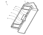
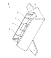
- the perspective view which shows the external appearance of the charging stand of embodiment of this invention The figure which shows the structure of the protection mechanism of the charging terminal of embodiment of this invention The figure explaining an example of the structure and operation
- the perspective view which shows the external appearance of the conventional charging stand The figure explaining a mode that a tablet terminal is mounted from the slanting horizontal direction to the conventional charge stand.
- the figure explaining a mode that a tablet terminal is mounted by sliding from the horizontal direction on the charging stand of embodiment of this invention.
- FIG. 1 shows the appearance of a charging stand 10 according to an embodiment of the present invention that charges a secondary battery built in an electronic terminal (not shown).
- the charging stand 10 has a table 1 suitable for charging a tablet terminal or the like as an electronic terminal.
- the electronic terminal will be described as a tablet terminal.
- the cradle 1 of the charging stand 10 is provided with a pair of charging terminals 2 at positions corresponding to the pair of power receiving terminals provided on the bottom surface of the tablet terminal (not shown).
- the table 1 has a U-shaped cross section in which the height of the rear wall is higher than that of the front wall so that the tablet terminal can be easily placed from the front upper direction.
- a pair of retraction guards 3 for protecting the charging terminals are provided inside the pair of charging terminals 2 provided on the cradle 1. Further, a pair of outer guards 4 for protecting the pair of charging terminals 2 are provided outside the pair of charging terminals 2.
- the outer guide 4 also serves as a guide for positioning the tablet terminal and the charging stand 10.
- FIG. 2 is a diagram showing the structure of the charging terminal protection mechanism according to the embodiment of the present invention.
- FIG. 2 is a diagram illustrating a structure in which the housing of the cradle 1 is removed, and a pair of retraction guards 3 that are higher than the charging terminals 2 are provided inside the pair of charging terminals 2, Outside the pair of charging terminals 2, an outer guard 4 having a height higher than that of the charging terminal 2 and the retraction guard 3 is provided.
- the right charging terminal 2 is protected by the right evacuation guard 3 and the outer guard 4 when the tablet terminal is placed from the right oblique side direction, and when the tablet terminal is placed from the left oblique lateral direction, the left evacuation guard 3 and The left charging terminal 2 is protected by the outer guard 4.
- the evacuation guard 3 is retreated to the lower side when the tablet terminal is placed on the cradle 1 of the charging stand 10 from above the front surface, and is charged without evacuating to the lower side when placed on the oblique side.
- the terminal 2 is rotatably supported by a fulcrum provided on the cradle 1 so as to guard the terminal 2.
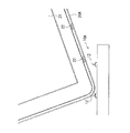
- FIG. 3 is a diagram for explaining an example of the structure and operation of the evacuation guard in FIG.
- the structure of the evacuation guard in FIG. 3 is merely an example.
- the retreat guard 3 has, for example, a substantially triangular shape protruding upward.
- One end on the outer side of each retraction guard 3, for example, the apex portion is rotatably held by a fulcrum 5 provided on the table 1.
- the pair of evacuation guards 3 are arranged at mirror target positions, and are connected to holes 6 provided at the inner apex portion so that the bottom is horizontal when the tablet terminal is not placed.
- the structure is pulled inward by an elastic body (spring) 7.
- the bottom sides of the pair of retraction guards 3 are held horizontally by the pulling force of the elastic body 7.
- the elastic body 7 is depicted as a spring, but the elastic body 7 is not limited to a spring, and may be, for example, rubber.
- FIG. 4 is a perspective view showing the appearance of the conventional charging stand.
- the conventional charging stand 10A has a table 1A suitable for charging a tablet terminal.
- the cradle 1A of the charging stand 10A is provided with a pair of charging terminals 12 at positions corresponding to the pair of power receiving terminals provided on the bottom surface of the tablet terminal (not shown). Outside the pair of charging terminals 12, an outer guide 14 for positioning the tablet terminal and the charging stand 10 ⁇ / b> A is provided.
- FIG. 5 is a diagram for explaining a state in which the tablet terminal 20A is placed on the conventional charging stand 10A from the oblique lateral direction.
- the tablet terminal 20 ⁇ / b> A has a touch panel 21 for performing an operation and a pair of power receiving terminals 22 for supplying a charging current to a built-in secondary battery.
- the tablet terminal 20 ⁇ / b> A is placed on the charging stand 10 ⁇ / b> A from above the front, the pair of power receiving terminals 22 and the pair of charging terminals 12 of the charging stand 10 ⁇ / b> A come into contact with each other and charging is performed.
- FIGS. 6 to 8 are diagrams for explaining how the tablet terminal 20 is placed on the charging station 10 according to the embodiment of the present invention.
- FIG. 7 is a diagram for explaining a state in which the tablet terminal 20 is placed from the lateral direction
- FIG. 7 is a diagram for explaining a state in which the tablet terminal 20 is slid from the lateral direction
- FIG. It is a figure explaining.
- FIG. 6 shows a state in which the tablet terminal 20 approaches the cradle 1 of the charging station 10 from the diagonally right lateral direction.
- the lower left corner of the tablet terminal 20 is in contact with the retraction guard 3.
- the evacuation guard 3 guards the left charging terminal 2 because it does not evacuate downward with respect to the force from the oblique lateral direction.
- FIG. 7 shows a state where the tablet terminal 20 is slid and placed on the outer guard 4 from the right to the left. Since the height of the outer guard 4 is higher than the height of the charging terminal 2 and the retraction guard 3, the tablet terminal 20 slides from the right to the left without touching the charging terminal 2 and the retraction guard 3.
- an alignment hole 23 is provided at the bottom of the tablet terminal 20, in which the outer guard 4 of the charging stand 10 is accommodated when the tablet terminal 20 is correctly placed on the charging stand 10. When 23 comes to the position of the outer guard 4, the alignment hole 23 and the outer guard 4 are fitted, and the tablet terminal 20 is properly placed on the charging stand 10.
- FIG. 8 shows a state in which the tablet terminal 20 is correctly placed on the charging stand 10.
- the outer guard 4 is accommodated in the alignment hole 23, the retraction guard 3 is retreated downward, and the pair of power receiving terminals 22 of the tablet terminal 20 and the pair of charging terminals 2 of the charging stand 10 are in contact with each other. Yes.
- a secondary battery (not shown) in the tablet terminal 20 is charged via the power receiving terminal 22 by the charging current output from the charging circuit in the charging stand 10. It will be.
- the electronic terminal is provided inside the pair of charging terminals, and when the electronic terminal is placed from the front upper direction, the electronic terminal is retracted to contact the charging terminal and the power receiving terminal.
- the terminal When the terminal is placed obliquely, it has a pair of retraction guards that guard the charging terminal without contacting the charging terminal and the power receiving terminal without retreating downward. Thereby, even if it mounts on a charging stand irrespective of the direction in which an electronic terminal is mounted, a charging terminal can be protected.
- the charging terminal protection mechanism can be configured with a small number of parts and a simple structure.
- the electronic terminal is described as being a tablet terminal, but the present invention is also applicable to electronic terminals other than tablet terminals.
- the pair of power receiving terminals of the electronic terminal and the pair of charging terminals of the charging stand have been described, but the power receiving terminal and the charging terminal are not limited to two.
- the present invention can be applied to a charging stand that has three power receiving terminals and three charging terminals, detects the type of the secondary battery by one terminal, and switches the charging control according to the detected type.
Landscapes
- Engineering & Computer Science (AREA)
- Theoretical Computer Science (AREA)
- Human Computer Interaction (AREA)
- Physics & Mathematics (AREA)
- General Engineering & Computer Science (AREA)
- General Physics & Mathematics (AREA)
- Power Engineering (AREA)
- Charge And Discharge Circuits For Batteries Or The Like (AREA)
- Details Of Connecting Devices For Male And Female Coupling (AREA)
- Power Sources (AREA)
Abstract
電子端末を置き台に斜横方向から載置しても充電端子が保護され、かつ電子端末を置き台に載置し易い充電スタンドを提供することを目的とする。本発明の充電端子の保護機構は、一対の受電端子を有する電子端末を載置する置き台上に一対の受電端子に対応する位置に設けられた一対の充電端子の内側に、一対の退避ガードを有している。この一対の退避ガードは、電子端末が前面上方向から載置されたときには下側に退避して充電端子と受電端子を接触させ、電子端末が斜横方向から載置されたときは下側に退避しないで充電端子と受電端子を接触させずに、充電端子をガードする。これにより、電子端末が充電スタンドに斜横方向から載置しても、充電スタンドの充電端子を保護することができ、かつ電子端末を充電スタンドへ載置し易くなる。
Description
本発明は、電子発注端末等のタブレット端末に内蔵されている二次電池を充電する充電スタンドの充電端子の保護機構、及びこの保護機構を備えた充電スタンドに関する。
下記特許文献1には、一対の充電端子の両側に、タブレット端末が載置されたことを検出する一対の載置検出スイッチを設けた充電スタンドの構造が提案されている。又、下記特許文献2には、被充電機器の角部が充電端子にぶつかり充電端子が損傷するのを防ぐために、充電端子の周囲に保護突起を設けた構造が提案されている。ここで、タブレット端末とは、略長方形の形状であり、片面に操作を行うタッチパネルが付いた端末をいう。
しかしながら、特許文献1及び2では、タブレット端末を斜横方向に充電スタンドに載置された場合の充電端子の保護は考慮されていない。即ち、特許文献1では、タブレット端末を前面上方向から載置することを想定しており、斜横方向から載置した場合には、タブレット端末の筐体の角部が充電端子に直接当たり、充電端子を損傷するおそれがある。又、特許文献2の充電端子の保護構造では、充電器に被充電機器を載置する方向が狭く、載置し難いという問題があった。
そこで、本発明は、タブレット端末を斜横方向から載置しても充電端子が保護され、かつタブレット端末を載置し易い充電端子の保護機構、及びこの保護機構を備えた充電スタンドを提供することを目的とする。
本発明の第1側面の充電端子の保護機構は、一対の受電端子を有する電子端末を載置する置き台上の前記一対の受電端子に対応する位置に設けられた一対の充電端子の保護機構であって、前記一対の充電端子の内側に設けられ、前記電子端末が前面上方向から載置されたときには下側に退避して前記充電端子と前記受電端子を接触させ、前記電子端末が斜横方向から載置されたときは下側に退避しないで前記充電端子と前記受電端子を接触させずに、前記充電端子をガードする一対の退避ガードと、を有することを特徴とする。
第2側面の充電スタンドは、電子端末に内蔵された二次電池を充電する充電スタンドであって、前記電子端末を載置する置き台と、前記置き台上に、前記電子端末が有する一対の受電端子に対応する位置に設けられた一対の充電端子と、前記一対の充電端子の内側に設けられ、前記電子端末が前面上方向から載置されたときには下側に退避して前記充電端子と前記受電端子を接触させ、前記電子端末が斜横方向から載置されたときは下側に退避しないで前記充電端子と前記受電端子を接触させずに、前記充電端子をガードする一対の退避ガードと、を有することを特徴とする。
本発明の充電端子の保護機構、及びこの保護機構を備えた充電スタンドによれば、電子端末が前面上方向から載置されたときには下側に退避して充電端子と受電端子を接触させ、電子端末が斜横方向から載置されたときは下側に退避しないで充電端子と受電端子を接触させずに、充電端子をガードする一対の退避ガードが、一対の充電端子の内側に設けられている。これにより、電子端末が充電スタンドに斜横方向から載置しても、充電スタンドの充電端子を保護することができ、かつ電子端末を充電スタンドへ載置し易くなる。
以下に本発明の実施形態について図面を参照しながら詳細に説明する。
(実施形態の構成)
図1には、図示しない電子端末に内蔵された二次電池を充電する本発明の実施形態の充電スタンド10の外観が示されている。充電スタンド10は、電子端末としてタブレット端末等を充電するのに好適な置き台1を有している。以下、電子端末は、タブレット端末であるとして説明する。
図1には、図示しない電子端末に内蔵された二次電池を充電する本発明の実施形態の充電スタンド10の外観が示されている。充電スタンド10は、電子端末としてタブレット端末等を充電するのに好適な置き台1を有している。以下、電子端末は、タブレット端末であるとして説明する。
充電スタンド10の有する置き台1には、図示しないタブレット端末の底面部に設けられている一対の受電端子に対応する位置に、一対の充電端子2が設けられている。置き台1の形状は、タブレット端末を前面上方向から載置し易いように、前の壁に較べ後ろの壁の高さを高くしたコの字形の横断面の形状をしている。
置き台1に設けられた一対の充電端子2の内側には、充電端子を保護するための一対の退避ガード3が設けられている。更に、一対の充電端子2の外側には、一対の充電端子2を保護するための一対の外ガード4が設けられている。尚、外ガイド4は、タブレット端末と充電スタンド10との位置決めのガイドの役目も果たす。
図2は、本発明の実施形態の充電端子の保護機構の構造を示す図である。
図2は、置き台1の筐体を外した構造を示す図であり、一対の充電端子2の内側には、充電端子2よりも高さの高い一対の退避ガード3が設けられ、更に、一対の充電端子2の外側には、充電端子2及び退避ガード3よりも高さが高い外ガード4が設けられている。
図2は、置き台1の筐体を外した構造を示す図であり、一対の充電端子2の内側には、充電端子2よりも高さの高い一対の退避ガード3が設けられ、更に、一対の充電端子2の外側には、充電端子2及び退避ガード3よりも高さが高い外ガード4が設けられている。
タブレット端末が右斜横方向から載置されたときには、右側の退避ガード3及び外ガード4により右側の充電端子2が保護され、左斜横方向から載置されたときには、左側の退避ガード3及び外ガード4により左側の充電端子2が保護される構造になっている。
退避ガード3は、タブレット端末が充電スタンド10の置き台1に、前面上方から載置されたときには、下側に退避し、斜横方向から載置されたときには、下側に退避せずに充電端子2をガードするように、置き台1に設けられた支点により回転自在に支持されている。
図3は、図2中の退避ガードの構造の一例及び動作を説明する図である。図3の退避ガードの構造は、一例に過ぎない。
退避ガード3は、図3に示されたように、例えば、上に凸な略三角形状をしている。各々の退避ガード3の外側の一端、例えば、頂点部分が置き台1に設けられた支点5により回転自在に保持されている。そして、一対の退避ガード3は、互いに鏡面対象な位置に配置され、タブレット端末が載置されていない時には、底辺が水平になるように、内側の頂点部分に設けられた孔6に接続された弾性体(バネ)7により内側に引っ張られる構造になっている。弾性体7の引っ張り力により、一対の退避ガード3の底辺が水平に保持されている。図3では、弾性体7はバネとして描かれているが、弾性体7はバネに限定されず、例えば、ゴム等でも良い。
図3において、タブレット端末が前面上方向から載置されると、退避ガード3は、支点5を中心に回転し、下方へ退避する。一方、タブレット端末が斜横方向から載置された場合には、支点5と力の作用点を結んだ垂線(モーメントアーム)の長さが短く、力のモーメントが小さくなるため、退避ガード3はほとんど下方に退避せずに充電端子2をガードする。
(実施形態の動作)
本発明の実施形態の充電端子の保護機構、及びこの保護機構を備えた充電スタンドについて、(I)従来の充電スタンドの構造と動作と、(II)本発明の実施形態の充電スタンドの動作と、に分けて説明する。
本発明の実施形態の充電端子の保護機構、及びこの保護機構を備えた充電スタンドについて、(I)従来の充電スタンドの構造と動作と、(II)本発明の実施形態の充電スタンドの動作と、に分けて説明する。
(I)従来の充電スタンドの構造と動作
図4は、従来の充電スタンドの外観を示す斜視図である。
図4は、従来の充電スタンドの外観を示す斜視図である。
従来の充電スタンド10Aは、タブレット端末を充電するのに好適な置き台1Aを有している。充電スタンド10Aの有する置き台1Aには、図示しないタブレット端末の底面部に設けられている一対の受電端子に対応する位置に、一対の充電端子12が設けられている。一対の充電端子12の外側には、タブレット端末と充電スタンド10Aとの位置決めをするための外ガイド14が設けられている。
図5は、従来の充電スタンド10Aに斜横方向からタブレット端末20Aが載置される様子をを説明する図である。
図5を参照すると、タブレット端末20Aは、操作を行うためのタッチパネル21と、内蔵されている二次電池に充電電流を供給する一対の受電端子22を有している。タブレット端末20Aが充電スタンド10Aに、前面上方向から載置された場合には、一対の受電端子22と充電スタンド10Aの一対の充電端子12とが接触し、充電が行われる。
従来の充電スタンド10Aにタブレット端末20Aが斜横方向から載置されると、タブレット端末20Aの角部が充電端子12に直接当たり、充電端子12を破損する虞があることがわかる。
(II)本発明の実施形態の充電スタンドの動作
図6~図8は、本発明の実施形態の充電スタンド10にタブレット端末20が載置される様子を説明する図であり、図6は斜横方向から載置される様子を説明する図、図7は横方向からスライドして載置される様子を説明する図、図8は充電スタンド10にタブレット端末20が正しく載置された状態を説明する図である。
図6~図8は、本発明の実施形態の充電スタンド10にタブレット端末20が載置される様子を説明する図であり、図6は斜横方向から載置される様子を説明する図、図7は横方向からスライドして載置される様子を説明する図、図8は充電スタンド10にタブレット端末20が正しく載置された状態を説明する図である。
図6には、タブレット端末20は、斜右横方向から充電スタンド10の置き台1に接近して来る様子が示されている。タブレット端末20の左下角部が、退避ガード3に接触している。上述したように、退避ガード3は、斜横方向からの力に対しては下方向に退避しないので、左側の充電端子2をガードする。
図7には、タブレット端末20が右から左方向へ外ガード4の上をスライドして載置される様子が示されている。外ガード4の高さは、充電端子2及び退避ガード3の高さより高いため、タブレット端末20は充電端子2及び退避ガード3に触れることなく、右から左方向へスライドして行く。タブレット端末20の底辺には、充電スタンド10にタブレット端末20が正しく載置されたときに、充電スタンド10の外ガード4が収まる位置合わせ孔23が設けられており、タブレット端末20の位置合わせ孔23が外ガード4に位置に来ると、位置合わせ孔23と外ガード4とが嵌合して、タブレット端末20が充電スタンド10の正しく載置された状態となる。
図8には、タブレット端末20が充電スタンド10に正しく載置された状態が示されている。図8を見ると、外ガード4が位置合わせ孔23に収まり、退避ガード3は下方に退避し、タブレット端末20の一対の受電端子22と充電スタンド10の一対の充電端子2とが接触している。タブレット端末20が充電スタンド10に正しく載置されると、充電スタンド10内の充電回路から出力される充電電流により、受電端子22を介してタブレット端末20内の図示しない二次電池が充電されることになる。
(実施形態の効果)
本発明の充電端子の保護機構によれば、一対の充電端子の内側に設けられ、電子端末が前面上方向から載置されたときには下側に退避して充電端子と受電端子を接触させ、電子端末が斜横方向から載置されたときは下側に退避しないで充電端子と受電端子を接触させずに、充電端子をガードする一対の退避ガードを有している。これにより、電子端末を載置される方向に関係なく、充電スタンドに載置しても、充電端子を保護することができる。
本発明の充電端子の保護機構によれば、一対の充電端子の内側に設けられ、電子端末が前面上方向から載置されたときには下側に退避して充電端子と受電端子を接触させ、電子端末が斜横方向から載置されたときは下側に退避しないで充電端子と受電端子を接触させずに、充電端子をガードする一対の退避ガードを有している。これにより、電子端末を載置される方向に関係なく、充電スタンドに載置しても、充電端子を保護することができる。
特に、図3に示した退避ガードの構造を採用することにより、少ない部品点数、かつ簡便な構造で充電端子の保護機構を構成することができる。
又、充電スタンド10の置き台1上に、充電端子2及び退避ガード3の高さより高い外ガード4を設けたことにより、図7に示したように、真横から電子端末をスライドさせる方法によっても載置することが可能になる。
(変形例)
本発明の変形例として、以下の(a)~(c)のようなものが考えられる。
本発明の変形例として、以下の(a)~(c)のようなものが考えられる。
(a) 本発明の実施形態の説明では、電子端末はタブレット端末であるとして説明したが、タブレット端末以外の電子端末にも適用可能である。
(b) 本発明の実施形態の説明では、電子端末の一対の受電端子及び充電スタンドの一対の充電端子として説明したが、受電端子及び充電端子は2つに限定されない。例えば、受電端子及び充電端子が3つあり、1つの端子により二次電池の種類を検出し、検出した種類に応じて充電制御を切り替える方式の充電スタンドにも適用可能である。
(c) 本発明の実施形態の説明では、充電スタンドの一対の外ガードは、電子端末の位置合わせ孔に嵌合して位置合わせの役割りをすると説明したが、外ガードと電子端末に設ける位置合わせ孔との組合せにより、電子端末の種類を識別するようにしても良い。
以上、本発明の実施形態について説明したが、本発明は、以上に述べた実施形態に限定されるものではなく、本発明の趣旨を逸脱しない範囲内で種々の構成又は実施形態を取ることができる。
1,1A 置き台
2,12 充電端子
3 退避ガード
4 外ガード
5 支点
6 孔
7 弾性体(バネ)
10,10A 充電スタンド
14 外ガイド
20,20A 電子端末(タブレット端末)
21 タッチパネル
22 受電端子
23 位置合わせ孔
2,12 充電端子
3 退避ガード
4 外ガード
5 支点
6 孔
7 弾性体(バネ)
10,10A 充電スタンド
14 外ガイド
20,20A 電子端末(タブレット端末)
21 タッチパネル
22 受電端子
23 位置合わせ孔
Claims (9)
- 一対の受電端子を有する電子端末を載置する置き台上の前記一対の受電端子に対応する位置に設けられた一対の充電端子の保護機構であって、
前記一対の充電端子の内側に設けられ、前記電子端末が前面上方向から載置されたときには下側に退避して前記充電端子と前記受電端子を接触させ、前記電子端末が斜横方向から載置されたときは下側に退避しないで前記充電端子と前記受電端子を接触させずに、前記充電端子をガードする一対の退避ガードと、
を有することを特徴とする充電端子の保護機構。 - 前記一対の退避ガードは、
前記退避ガードの外側の一端が前記置き台に設けられた支点により回転自在にそれぞれ固定され、前記退避ガードの内側の一端を互いに内側へ引っ張る弾性体が接続されていることを特徴とする請求項1に記載の充電端子の保護機構。 - 前記退避ガードの形状は、略三角形状であり、
前記電子端末が前記置き台に載置されていない時には、前記略三角形が上に凸かつ底辺が水平になるように、前記退避ガードの内側の頂点同士が前記弾性体の引っ張り力により維持されることを特徴とする請求項2に記載の充電端子の保護機構。 - 前記一対の充電端子の外側には、前記電子端末が斜横方向から載置されたときに前記電子端末の角部が前記充電端子に接触することを防ぐ一対の外ガードを有することを特徴とすることを特徴とする請求項1~3のいずれか1項に記載の充電端子の保護機構。
- 電子端末に内蔵された二次電池を充電する充電スタンドであって、
前記電子端末を載置する置き台と、
前記置き台上に、前記電子端末が有する一対の受電端子に対応する位置に設けられた一対の充電端子と、
前記一対の充電端子の内側に設けられ、前記電子端末が前面上方向から載置されたときには下側に退避して前記充電端子と前記受電端子を接触させ、前記電子端末が斜横方向から載置されたときは下側に退避しないで前記充電端子と前記受電端子を接触させずに、前記充電端子をガードする一対の退避ガードと、
を有することを特徴とする充電スタンド。 - 前記一対の退避ガードは、
前記退避ガードの外側の一端が前記置き台に設けられた支点により回転自在にそれぞれ固定され、前記退避ガードの内側の一端に互いに内側へ引っ張り合う弾性体が接続されていることを特徴とする請求項5に記載の充電スタンド。 - 前記一対の充電端子の外側には、前記電子端末が斜横方向から載置されたときに前記電子端末の角部が前記充電端子に接触することを防ぐ一対の外ガードを有することを特徴とする請求項5又は6に記載の充電スタンド。
- 前記一対の外ガードは、前記電子端末と前記置き台との位置を確定する機能を有することを特徴とする請求項7に記載の充電スタンド。
- 前記電子端末は、タブレット端末であり、
前記置き台は、前記タブレット端末に嵌合する形状であることを特徴とする請求項5~8のいずれか1項に記載の充電スタンド。
Priority Applications (3)
| Application Number | Priority Date | Filing Date | Title |
|---|---|---|---|
| PCT/JP2014/084065 WO2016103345A1 (ja) | 2014-12-24 | 2014-12-24 | 充電端子の保護機構、及びこの保護機構を備えた充電スタンド |
| JP2016565642A JP6178024B2 (ja) | 2014-12-24 | 2014-12-24 | 充電端子の保護機構、及びこの保護機構を備えた充電スタンド |
| TW104137560A TW201629675A (zh) | 2014-12-24 | 2015-11-13 | 充電端子的保護機構、及具備該保護機構的充電座 |
Applications Claiming Priority (1)
| Application Number | Priority Date | Filing Date | Title |
|---|---|---|---|
| PCT/JP2014/084065 WO2016103345A1 (ja) | 2014-12-24 | 2014-12-24 | 充電端子の保護機構、及びこの保護機構を備えた充電スタンド |
Publications (1)
| Publication Number | Publication Date |
|---|---|
| WO2016103345A1 true WO2016103345A1 (ja) | 2016-06-30 |
Family
ID=56149446
Family Applications (1)
| Application Number | Title | Priority Date | Filing Date |
|---|---|---|---|
| PCT/JP2014/084065 Ceased WO2016103345A1 (ja) | 2014-12-24 | 2014-12-24 | 充電端子の保護機構、及びこの保護機構を備えた充電スタンド |
Country Status (3)
| Country | Link |
|---|---|
| JP (1) | JP6178024B2 (ja) |
| TW (1) | TW201629675A (ja) |
| WO (1) | WO2016103345A1 (ja) |
Citations (3)
| Publication number | Priority date | Publication date | Assignee | Title |
|---|---|---|---|---|
| JP2000340302A (ja) * | 1999-05-28 | 2000-12-08 | Nec Eng Ltd | コネクタ |
| JP2005217571A (ja) * | 2004-01-28 | 2005-08-11 | Nec Engineering Ltd | 接触端子構造 |
| JP2014153976A (ja) * | 2013-02-12 | 2014-08-25 | Almex Inc | タブレット端末用ジャケット及び飲食注文端末 |
-
2014
- 2014-12-24 JP JP2016565642A patent/JP6178024B2/ja active Active
- 2014-12-24 WO PCT/JP2014/084065 patent/WO2016103345A1/ja not_active Ceased
-
2015
- 2015-11-13 TW TW104137560A patent/TW201629675A/zh unknown
Patent Citations (3)
| Publication number | Priority date | Publication date | Assignee | Title |
|---|---|---|---|---|
| JP2000340302A (ja) * | 1999-05-28 | 2000-12-08 | Nec Eng Ltd | コネクタ |
| JP2005217571A (ja) * | 2004-01-28 | 2005-08-11 | Nec Engineering Ltd | 接触端子構造 |
| JP2014153976A (ja) * | 2013-02-12 | 2014-08-25 | Almex Inc | タブレット端末用ジャケット及び飲食注文端末 |
Also Published As
| Publication number | Publication date |
|---|---|
| TW201629675A (zh) | 2016-08-16 |
| JP6178024B2 (ja) | 2017-08-09 |
| JPWO2016103345A1 (ja) | 2017-04-27 |
Similar Documents
| Publication | Publication Date | Title |
|---|---|---|
| CN105518769B (zh) | 柔性屏扩展结构、柔性屏组件及终端 | |
| CN202145582U (zh) | 自动收纳的充电结构 | |
| CN202166971U (zh) | 一种携带式键盘保护支撑套 | |
| US9312709B2 (en) | Charging stand | |
| US20160091925A1 (en) | Adaptive docking station | |
| US9397718B2 (en) | Mobile telephone holding device | |
| CN106231044B (zh) | 终端的保护装置 | |
| TW201340526A (zh) | 無線充電裝置 | |
| US10389057B2 (en) | Charger for microphone | |
| JP6178024B2 (ja) | 充電端子の保護機構、及びこの保護機構を備えた充電スタンド | |
| CN202759277U (zh) | 一种手机充电座 | |
| US12451919B2 (en) | Modular customizable ruggedized protective case with detachable sidewall for mobile device | |
| CN104718675A (zh) | 真空断路器 | |
| JP2012231655A (ja) | 充電装置 | |
| TW201327605A (zh) | 具有伸縮機構的裝置 | |
| KR20160117136A (ko) | 접속 단자 장치 및 이를 구비한 전자 장치 | |
| US20130044408A1 (en) | Docking station | |
| JP2012100388A (ja) | 電気自動車用充電キャビネット | |
| JP2011138629A (ja) | 電子機器 | |
| JP5718307B2 (ja) | 着脱機構およびクレードル、並びに電子機器システム | |
| JP4908659B2 (ja) | 電子機器 | |
| TWI542087B (zh) | 可攜式電子裝置及擴充座 | |
| JP3183800U (ja) | 受電電極を覆う複数のシャッターを有する受電端末の構造 | |
| JP2012230799A (ja) | 充電台 | |
| JP6411547B2 (ja) | クレードル、及び、携帯型電子機器セット |
Legal Events
| Date | Code | Title | Description |
|---|---|---|---|
| 121 | Ep: the epo has been informed by wipo that ep was designated in this application |
Ref document number: 14908953 Country of ref document: EP Kind code of ref document: A1 |
|
| ENP | Entry into the national phase |
Ref document number: 2016565642 Country of ref document: JP Kind code of ref document: A |
|
| NENP | Non-entry into the national phase |
Ref country code: DE |
|
| 122 | Ep: pct application non-entry in european phase |
Ref document number: 14908953 Country of ref document: EP Kind code of ref document: A1 |