WO2016098903A1 - Saddle-type vehicle - Google Patents
Saddle-type vehicle Download PDFInfo
- Publication number
- WO2016098903A1 WO2016098903A1 PCT/JP2015/085589 JP2015085589W WO2016098903A1 WO 2016098903 A1 WO2016098903 A1 WO 2016098903A1 JP 2015085589 W JP2015085589 W JP 2015085589W WO 2016098903 A1 WO2016098903 A1 WO 2016098903A1
- Authority
- WO
- WIPO (PCT)
- Prior art keywords
- catalyst
- exhaust
- exhaust passage
- upstream
- engine
- Prior art date
Links
Images


Classifications
-
- F—MECHANICAL ENGINEERING; LIGHTING; HEATING; WEAPONS; BLASTING
- F01—MACHINES OR ENGINES IN GENERAL; ENGINE PLANTS IN GENERAL; STEAM ENGINES
- F01N—GAS-FLOW SILENCERS OR EXHAUST APPARATUS FOR MACHINES OR ENGINES IN GENERAL; GAS-FLOW SILENCERS OR EXHAUST APPARATUS FOR INTERNAL COMBUSTION ENGINES
- F01N3/00—Exhaust or silencing apparatus having means for purifying, rendering innocuous, or otherwise treating exhaust
- F01N3/08—Exhaust or silencing apparatus having means for purifying, rendering innocuous, or otherwise treating exhaust for rendering innocuous
- F01N3/10—Exhaust or silencing apparatus having means for purifying, rendering innocuous, or otherwise treating exhaust for rendering innocuous by thermal or catalytic conversion of noxious components of exhaust
- F01N3/18—Exhaust or silencing apparatus having means for purifying, rendering innocuous, or otherwise treating exhaust for rendering innocuous by thermal or catalytic conversion of noxious components of exhaust characterised by methods of operation; Control
- F01N3/20—Exhaust or silencing apparatus having means for purifying, rendering innocuous, or otherwise treating exhaust for rendering innocuous by thermal or catalytic conversion of noxious components of exhaust characterised by methods of operation; Control specially adapted for catalytic conversion ; Methods of operation or control of catalytic converters
-
- B—PERFORMING OPERATIONS; TRANSPORTING
- B62—LAND VEHICLES FOR TRAVELLING OTHERWISE THAN ON RAILS
- B62M—RIDER PROPULSION OF WHEELED VEHICLES OR SLEDGES; POWERED PROPULSION OF SLEDGES OR SINGLE-TRACK CYCLES; TRANSMISSIONS SPECIALLY ADAPTED FOR SUCH VEHICLES
- B62M7/00—Motorcycles characterised by position of motor or engine
- B62M7/02—Motorcycles characterised by position of motor or engine with engine between front and rear wheels
-
- F—MECHANICAL ENGINEERING; LIGHTING; HEATING; WEAPONS; BLASTING
- F01—MACHINES OR ENGINES IN GENERAL; ENGINE PLANTS IN GENERAL; STEAM ENGINES
- F01N—GAS-FLOW SILENCERS OR EXHAUST APPARATUS FOR MACHINES OR ENGINES IN GENERAL; GAS-FLOW SILENCERS OR EXHAUST APPARATUS FOR INTERNAL COMBUSTION ENGINES
- F01N13/00—Exhaust or silencing apparatus characterised by constructional features ; Exhaust or silencing apparatus, or parts thereof, having pertinent characteristics not provided for in, or of interest apart from, groups F01N1/00 - F01N5/00, F01N9/00, F01N11/00
- F01N13/002—Apparatus adapted for particular uses, e.g. for portable devices driven by machines or engines
-
- F—MECHANICAL ENGINEERING; LIGHTING; HEATING; WEAPONS; BLASTING
- F01—MACHINES OR ENGINES IN GENERAL; ENGINE PLANTS IN GENERAL; STEAM ENGINES
- F01N—GAS-FLOW SILENCERS OR EXHAUST APPARATUS FOR MACHINES OR ENGINES IN GENERAL; GAS-FLOW SILENCERS OR EXHAUST APPARATUS FOR INTERNAL COMBUSTION ENGINES
- F01N13/00—Exhaust or silencing apparatus characterised by constructional features ; Exhaust or silencing apparatus, or parts thereof, having pertinent characteristics not provided for in, or of interest apart from, groups F01N1/00 - F01N5/00, F01N9/00, F01N11/00
- F01N13/009—Exhaust or silencing apparatus characterised by constructional features ; Exhaust or silencing apparatus, or parts thereof, having pertinent characteristics not provided for in, or of interest apart from, groups F01N1/00 - F01N5/00, F01N9/00, F01N11/00 having two or more separate purifying devices arranged in series
- F01N13/0093—Exhaust or silencing apparatus characterised by constructional features ; Exhaust or silencing apparatus, or parts thereof, having pertinent characteristics not provided for in, or of interest apart from, groups F01N1/00 - F01N5/00, F01N9/00, F01N11/00 having two or more separate purifying devices arranged in series the purifying devices are of the same type
-
- F—MECHANICAL ENGINEERING; LIGHTING; HEATING; WEAPONS; BLASTING
- F01—MACHINES OR ENGINES IN GENERAL; ENGINE PLANTS IN GENERAL; STEAM ENGINES
- F01N—GAS-FLOW SILENCERS OR EXHAUST APPARATUS FOR MACHINES OR ENGINES IN GENERAL; GAS-FLOW SILENCERS OR EXHAUST APPARATUS FOR INTERNAL COMBUSTION ENGINES
- F01N13/00—Exhaust or silencing apparatus characterised by constructional features ; Exhaust or silencing apparatus, or parts thereof, having pertinent characteristics not provided for in, or of interest apart from, groups F01N1/00 - F01N5/00, F01N9/00, F01N11/00
- F01N13/08—Other arrangements or adaptations of exhaust conduits
- F01N13/10—Other arrangements or adaptations of exhaust conduits of exhaust manifolds
-
- F—MECHANICAL ENGINEERING; LIGHTING; HEATING; WEAPONS; BLASTING
- F01—MACHINES OR ENGINES IN GENERAL; ENGINE PLANTS IN GENERAL; STEAM ENGINES
- F01N—GAS-FLOW SILENCERS OR EXHAUST APPARATUS FOR MACHINES OR ENGINES IN GENERAL; GAS-FLOW SILENCERS OR EXHAUST APPARATUS FOR INTERNAL COMBUSTION ENGINES
- F01N3/00—Exhaust or silencing apparatus having means for purifying, rendering innocuous, or otherwise treating exhaust
- F01N3/08—Exhaust or silencing apparatus having means for purifying, rendering innocuous, or otherwise treating exhaust for rendering innocuous
- F01N3/10—Exhaust or silencing apparatus having means for purifying, rendering innocuous, or otherwise treating exhaust for rendering innocuous by thermal or catalytic conversion of noxious components of exhaust
- F01N3/101—Three-way catalysts
-
- F—MECHANICAL ENGINEERING; LIGHTING; HEATING; WEAPONS; BLASTING
- F01—MACHINES OR ENGINES IN GENERAL; ENGINE PLANTS IN GENERAL; STEAM ENGINES
- F01N—GAS-FLOW SILENCERS OR EXHAUST APPARATUS FOR MACHINES OR ENGINES IN GENERAL; GAS-FLOW SILENCERS OR EXHAUST APPARATUS FOR INTERNAL COMBUSTION ENGINES
- F01N3/00—Exhaust or silencing apparatus having means for purifying, rendering innocuous, or otherwise treating exhaust
- F01N3/08—Exhaust or silencing apparatus having means for purifying, rendering innocuous, or otherwise treating exhaust for rendering innocuous
- F01N3/10—Exhaust or silencing apparatus having means for purifying, rendering innocuous, or otherwise treating exhaust for rendering innocuous by thermal or catalytic conversion of noxious components of exhaust
- F01N3/105—General auxiliary catalysts, e.g. upstream or downstream of the main catalyst
-
- F—MECHANICAL ENGINEERING; LIGHTING; HEATING; WEAPONS; BLASTING
- F01—MACHINES OR ENGINES IN GENERAL; ENGINE PLANTS IN GENERAL; STEAM ENGINES
- F01N—GAS-FLOW SILENCERS OR EXHAUST APPARATUS FOR MACHINES OR ENGINES IN GENERAL; GAS-FLOW SILENCERS OR EXHAUST APPARATUS FOR INTERNAL COMBUSTION ENGINES
- F01N3/00—Exhaust or silencing apparatus having means for purifying, rendering innocuous, or otherwise treating exhaust
- F01N3/08—Exhaust or silencing apparatus having means for purifying, rendering innocuous, or otherwise treating exhaust for rendering innocuous
- F01N3/10—Exhaust or silencing apparatus having means for purifying, rendering innocuous, or otherwise treating exhaust for rendering innocuous by thermal or catalytic conversion of noxious components of exhaust
- F01N3/24—Exhaust or silencing apparatus having means for purifying, rendering innocuous, or otherwise treating exhaust for rendering innocuous by thermal or catalytic conversion of noxious components of exhaust characterised by constructional aspects of converting apparatus
- F01N3/28—Construction of catalytic reactors
-
- F—MECHANICAL ENGINEERING; LIGHTING; HEATING; WEAPONS; BLASTING
- F01—MACHINES OR ENGINES IN GENERAL; ENGINE PLANTS IN GENERAL; STEAM ENGINES
- F01N—GAS-FLOW SILENCERS OR EXHAUST APPARATUS FOR MACHINES OR ENGINES IN GENERAL; GAS-FLOW SILENCERS OR EXHAUST APPARATUS FOR INTERNAL COMBUSTION ENGINES
- F01N13/00—Exhaust or silencing apparatus characterised by constructional features ; Exhaust or silencing apparatus, or parts thereof, having pertinent characteristics not provided for in, or of interest apart from, groups F01N1/00 - F01N5/00, F01N9/00, F01N11/00
- F01N13/14—Exhaust or silencing apparatus characterised by constructional features ; Exhaust or silencing apparatus, or parts thereof, having pertinent characteristics not provided for in, or of interest apart from, groups F01N1/00 - F01N5/00, F01N9/00, F01N11/00 having thermal insulation
- F01N13/141—Double-walled exhaust pipes or housings
- F01N13/143—Double-walled exhaust pipes or housings with air filling the space between both walls
-
- F—MECHANICAL ENGINEERING; LIGHTING; HEATING; WEAPONS; BLASTING
- F01—MACHINES OR ENGINES IN GENERAL; ENGINE PLANTS IN GENERAL; STEAM ENGINES
- F01N—GAS-FLOW SILENCERS OR EXHAUST APPARATUS FOR MACHINES OR ENGINES IN GENERAL; GAS-FLOW SILENCERS OR EXHAUST APPARATUS FOR INTERNAL COMBUSTION ENGINES
- F01N2240/00—Combination or association of two or more different exhaust treating devices, or of at least one such device with an auxiliary device, not covered by indexing codes F01N2230/00 or F01N2250/00, one of the devices being
- F01N2240/20—Combination or association of two or more different exhaust treating devices, or of at least one such device with an auxiliary device, not covered by indexing codes F01N2230/00 or F01N2250/00, one of the devices being a flow director or deflector
-
- F—MECHANICAL ENGINEERING; LIGHTING; HEATING; WEAPONS; BLASTING
- F01—MACHINES OR ENGINES IN GENERAL; ENGINE PLANTS IN GENERAL; STEAM ENGINES
- F01N—GAS-FLOW SILENCERS OR EXHAUST APPARATUS FOR MACHINES OR ENGINES IN GENERAL; GAS-FLOW SILENCERS OR EXHAUST APPARATUS FOR INTERNAL COMBUSTION ENGINES
- F01N2260/00—Exhaust treating devices having provisions not otherwise provided for
- F01N2260/08—Exhaust treating devices having provisions not otherwise provided for for preventing heat loss or temperature drop, using other means than layers of heat-insulating material
-
- F—MECHANICAL ENGINEERING; LIGHTING; HEATING; WEAPONS; BLASTING
- F01—MACHINES OR ENGINES IN GENERAL; ENGINE PLANTS IN GENERAL; STEAM ENGINES
- F01N—GAS-FLOW SILENCERS OR EXHAUST APPARATUS FOR MACHINES OR ENGINES IN GENERAL; GAS-FLOW SILENCERS OR EXHAUST APPARATUS FOR INTERNAL COMBUSTION ENGINES
- F01N2260/00—Exhaust treating devices having provisions not otherwise provided for
- F01N2260/20—Exhaust treating devices having provisions not otherwise provided for for heat or sound protection, e.g. using a shield or specially shaped outer surface of exhaust device
-
- F—MECHANICAL ENGINEERING; LIGHTING; HEATING; WEAPONS; BLASTING
- F01—MACHINES OR ENGINES IN GENERAL; ENGINE PLANTS IN GENERAL; STEAM ENGINES
- F01N—GAS-FLOW SILENCERS OR EXHAUST APPARATUS FOR MACHINES OR ENGINES IN GENERAL; GAS-FLOW SILENCERS OR EXHAUST APPARATUS FOR INTERNAL COMBUSTION ENGINES
- F01N2590/00—Exhaust or silencing apparatus adapted to particular use, e.g. for military applications, airplanes, submarines
- F01N2590/04—Exhaust or silencing apparatus adapted to particular use, e.g. for military applications, airplanes, submarines for motorcycles
-
- F—MECHANICAL ENGINEERING; LIGHTING; HEATING; WEAPONS; BLASTING
- F02—COMBUSTION ENGINES; HOT-GAS OR COMBUSTION-PRODUCT ENGINE PLANTS
- F02B—INTERNAL-COMBUSTION PISTON ENGINES; COMBUSTION ENGINES IN GENERAL
- F02B61/00—Adaptations of engines for driving vehicles or for driving propellers; Combinations of engines with gearing
- F02B61/02—Adaptations of engines for driving vehicles or for driving propellers; Combinations of engines with gearing for driving cycles
-
- Y—GENERAL TAGGING OF NEW TECHNOLOGICAL DEVELOPMENTS; GENERAL TAGGING OF CROSS-SECTIONAL TECHNOLOGIES SPANNING OVER SEVERAL SECTIONS OF THE IPC; TECHNICAL SUBJECTS COVERED BY FORMER USPC CROSS-REFERENCE ART COLLECTIONS [XRACs] AND DIGESTS
- Y02—TECHNOLOGIES OR APPLICATIONS FOR MITIGATION OR ADAPTATION AGAINST CLIMATE CHANGE
- Y02A—TECHNOLOGIES FOR ADAPTATION TO CLIMATE CHANGE
- Y02A50/00—TECHNOLOGIES FOR ADAPTATION TO CLIMATE CHANGE in human health protection, e.g. against extreme weather
- Y02A50/20—Air quality improvement or preservation, e.g. vehicle emission control or emission reduction by using catalytic converters
-
- Y—GENERAL TAGGING OF NEW TECHNOLOGICAL DEVELOPMENTS; GENERAL TAGGING OF CROSS-SECTIONAL TECHNOLOGIES SPANNING OVER SEVERAL SECTIONS OF THE IPC; TECHNICAL SUBJECTS COVERED BY FORMER USPC CROSS-REFERENCE ART COLLECTIONS [XRACs] AND DIGESTS
- Y02—TECHNOLOGIES OR APPLICATIONS FOR MITIGATION OR ADAPTATION AGAINST CLIMATE CHANGE
- Y02T—CLIMATE CHANGE MITIGATION TECHNOLOGIES RELATED TO TRANSPORTATION
- Y02T10/00—Road transport of goods or passengers
- Y02T10/10—Internal combustion engine [ICE] based vehicles
- Y02T10/12—Improving ICE efficiencies
Definitions
- the present invention relates to a saddle riding type vehicle.
- a straddle-type vehicle that includes an engine unit having a configuration in which a plurality of independent exhaust passages are connected to the engine body.
- the exhaust gas discharged from the engine body flows into the plurality of independent exhaust passage portions.
- the plurality of independent exhaust passage portions are connected to the catalyst portion via the collective exhaust passage portion.
- Exhaust gases discharged from the plurality of independent exhaust passage portions are collected in the collective exhaust passage portion.
- a catalyst for purifying exhaust gas is disposed inside the catalyst portion.
- the catalyst part is disposed, for example, below the engine body (see, for example, Patent Document 1).
- the cross-sectional area of the catalyst portion is larger than the cross-sectional area of the collective exhaust passage portion.
- the cross-sectional area is an area of a cross section orthogonal to the flow direction of the exhaust gas.
- Patent Document 1 employs the following configuration.
- two independent exhaust passage portions are connected to the collective exhaust passage portion two by two.
- the two collective exhaust passage portions are connected to the two catalyst portions, respectively.
- the two catalyst parts are arranged side by side in the vehicle width direction. That is, in patent document 1, the catalyst provided with respect to four independent exhaust passage parts is divided into two, and they are arranged side by side in the vehicle width direction. Thereby, the vertical length of the catalyst portion is reduced.
- the layout of the catalyst is devised to suppress the increase in the size of the vehicle in the vertical direction while ensuring the separation distance between the ground and the catalyst portion.
- An object of the present invention is to provide a straddle-type vehicle in which a catalyst is disposed below an engine body, which can suppress an increase in vertical size of the vehicle while improving exhaust gas purification performance by the catalyst.
- An increase in the size of the catalyst has been considered as means for improving the exhaust gas purification performance of the catalyst.
- the inventor of the present application reexamined the reason why the catalyst is enlarged.
- An engine unit having a plurality of independent exhaust passages connected to the engine body often has a plurality of combustion chambers.
- an engine unit having a plurality of combustion chambers repeatedly performs an intake stroke, a compression stroke, a combustion stroke (expansion stroke), and an exhaust stroke at different timings for each combustion chamber. Therefore, the pressure fluctuations in the plurality of independent exhaust passage portions are different. Therefore, a certain problem arises when the collective exhaust passage portion and the catalyst portion are arranged in the front-rear direction below the engine body as in Patent Document 1 described above.
- the inventor of the present application has thought that if the deviation of the passage position of the exhaust gas in the catalyst is suppressed, the increase in the size of the catalyst can be suppressed while maintaining the exhaust purification performance of the catalyst.
- the inventors have come up with an idea of the arrangement position and shape of the collective exhaust passage portion arranged between the plurality of independent exhaust passage portions and the catalyst portion arranged below the engine body.
- a straddle-type vehicle includes a vehicle body frame, an engine unit supported by the vehicle body frame, and at least one front wheel.
- a front wheel portion disposed in front of the engine unit, and a rear wheel portion including at least one rear wheel and disposed rearward of the engine unit in the front-rear direction when viewed in the left-right direction.
- the engine unit has a crankcase portion including a crankshaft having a central axis along the left-right direction, and is partially provided by a plurality of cylinder holes adjacent to each other along the left-right direction and the plurality of cylinder holes.
- An engine main body having a plurality of combustion chambers, and a plurality of exhaust ports communicating with the plurality of combustion chambers formed on the front surface thereof, and connected to the plurality of exhaust ports of the engine main body, And an exhaust device having an atmospheric discharge port for discharging exhaust gas to the atmosphere.
- the exhaust device is connected to the plurality of exhaust ports of the engine body, respectively, and includes a plurality of independent exhaust passage portions through which exhaust gas discharged from the engine body flows, and the plurality of combustion chambers to the atmosphere discharge port.
- a main catalyst that most purifies the exhaust gas discharged from the plurality of combustion chambers, and the length of the exhaust gas in the flow direction is the same as the length of the main catalyst in the flow direction of the exhaust gas, At least a part of the crankcase part is disposed below the vehicle in the vertical direction, and the engine lower catalyst part is disposed such that the flow direction of the exhaust gas flowing through the crankcase part is along the horizontal direction.
- the saddle riding type vehicle includes a body frame, an engine unit, a front wheel portion, and a rear wheel portion.
- the left-right direction, the front-rear direction, and the up-down direction are the left-right direction of the vehicle, the front-rear direction of the vehicle, and the up-down direction of the vehicle, respectively.
- the engine unit is supported by the body frame.
- the front wheel portion includes at least one front wheel.
- the front wheel portion is disposed in front of the engine unit when viewed in the left-right direction.
- the rear wheel portion includes at least one rear wheel.
- the rear wheel portion is disposed behind the engine unit when viewed in the left-right direction.
- the engine unit includes an engine body and an exhaust device.
- the engine body has a crankcase portion.
- the crankcase portion includes a crankshaft having a central axis along the left-right direction.
- the engine body has a plurality of cylinder holes and a plurality of combustion chambers.
- the plurality of cylinder holes are adjacent along the left-right direction. Part of the plurality of combustion chambers is partitioned by a plurality of cylinder holes, respectively.
- a plurality of exhaust ports communicating with the plurality of combustion chambers are formed on the front surface of the engine body.
- the exhaust device is connected to a plurality of exhaust ports of the engine body.
- the exhaust device has an atmospheric discharge port for discharging exhaust gas to the atmosphere.
- the exhaust device includes a plurality of independent exhaust passage portions, an engine lower catalyst portion, and an upstream collective exhaust passage portion.
- the plurality of independent exhaust passage portions are respectively connected to the plurality of exhaust ports of the engine body. Exhaust gas discharged from the engine body flows through the plurality of independent exhaust passage portions.
- the engine lower catalyst part has a main catalyst. The main catalyst most purifies the exhaust gas discharged from the plurality of combustion chambers in the plurality of exhaust paths from the plurality of combustion chambers to the atmospheric discharge ports.
- the length in the exhaust gas flow direction of the engine lower catalyst portion is the same as the length of the main catalyst in the exhaust gas flow direction.
- the upstream collective exhaust passage portion is connected to the downstream ends of the plurality of independent exhaust passage portions and the upstream end of the engine lower catalyst portion.
- the engine lower catalyst portion is disposed below the crankcase portion.
- the engine lower catalyst part is arranged so that the flow direction of the exhaust gas flowing through the engine lower part becomes a direction along the horizontal direction.
- the direction along the horizontal direction is not limited to the direction parallel to the horizontal direction. Including a direction inclined within a range of ⁇ 45 ° with respect to the horizontal direction.
- at least a part of the upstream collective exhaust passage portion connected to the upstream end of the engine lower catalyst portion is disposed in front of the engine body. Therefore, the path length of the upstream collective exhaust passage portion can be made longer than when the upstream collective exhaust passage portion is not disposed in front of the engine body.
- the upstream collecting exhaust passage portion has a bent portion.
- the bent portion changes the flow direction of the exhaust gas flowing through the bent portion from the direction along the vertical direction to the direction along the horizontal direction.
- the exhaust gas is more easily diffused in the upstream collective exhaust passage portion.
- the straddle-type vehicle of the present invention preferably has the following configuration.
- the engine body is arranged such that center axes of the plurality of cylinder holes are along the vertical direction.
- the engine body is arranged such that the central axes of the plurality of cylinder holes are along the vertical direction.
- the fact that the central axis is along the vertical direction is not limited to the case where the central axis is parallel to the vertical direction. This includes the case where the central axis is inclined within a range of ⁇ 45 ° with respect to the vertical direction.
- the upstream collective exhaust passage portion has a longer path length than the case where the engine body is arranged such that the center axis of the cylinder hole is along the front-rear direction. Thereby, the exhaust gas is more easily diffused in the upstream collective exhaust passage portion.
- the deviation of the exhaust gas passage position in the main catalyst can be further suppressed. Therefore, it is possible to improve the exhaust purification performance of the main catalyst while maintaining the size of the main catalyst as compared with the case where there is a bias. As a result, it is possible to suppress an increase in the size of the vehicle in the vertical direction while improving the exhaust purification performance of the main catalyst.
- the straddle-type vehicle of the present invention preferably has the following configuration. At least a part of the engine lower catalyst portion is disposed in front of the center axis of the crankshaft in the front-rear direction.
- the engine lower catalyst portion is disposed in front of the center axis of the crankshaft. Therefore, the engine lower catalyst portion can be disposed further forward than the case where the engine lower catalyst portion is disposed rearward of the center axis of the crankshaft. Therefore, the path length from the combustion chamber to the engine lower catalyst portion is shortened. Therefore, the temperature of the exhaust gas flowing into the main catalyst becomes higher. Thereby, when the engine unit is cold started, the time until the main catalyst is activated from the inactive state is further shortened. As a result, the exhaust purification performance of the main catalyst can be further improved.
- the cold start of the engine unit means that the engine unit is started in a state where the temperature of the engine main body is at the outside air temperature or lower.
- the straddle-type vehicle of the present invention preferably has the following configuration.
- at least a part of the engine lower catalyst portion is disposed rearward in the front-rear direction of a straight line that is orthogonal to the center axis of the cylinder hole and passes through the center axis of the crankshaft.
- a straight line that is orthogonal to the center axis of the cylinder bore and passes through the center axis of the crankshaft is defined as a straight line L.
- the upstream collective exhaust passage portion has a longer path length. Thereby, the exhaust gas is more easily diffused in the upstream collective exhaust passage portion. Therefore, the deviation of the exhaust gas passage position in the main catalyst can be further suppressed.
- the straddle-type vehicle of the present invention may have the following configuration.
- the engine body is arranged such that center axes of the plurality of cylinder holes are along the front-rear direction.
- the engine body is arranged such that the central axes of the plurality of cylinder holes are along the front-rear direction. Therefore, the vertical length of the engine body is short. Therefore, the upsizing of the vehicle can be further suppressed.
- the direction along the horizontal direction is not limited to the direction parallel to the horizontal direction. Including a direction inclined within a range of ⁇ 45 ° with respect to the horizontal direction.
- the straddle-type vehicle of the present invention may have the following configuration. At least a part of the engine lower catalyst portion is disposed behind the center axis of the crankshaft in the front-rear direction.
- the upstream collective exhaust passage portion has a longer path length than the case where the entire engine lower catalyst portion is disposed forward of the center axis of the crankshaft.
- the exhaust gas is more easily diffused in the upstream collective exhaust passage portion. Therefore, the deviation of the exhaust gas passage position in the main catalyst can be further suppressed. Therefore, it is possible to improve the exhaust purification performance of the main catalyst while maintaining the size of the main catalyst as compared with the case where there is a bias. As a result, it is possible to suppress an increase in the size of the vehicle in the vertical direction while improving the exhaust purification performance of the main catalyst.
- the straddle-type vehicle of the present invention may have the following configuration.
- the engine unit includes a power transmission device that transmits a rotational force of the crankshaft to the rear wheel portion.
- the power transmission device includes a drive rotator that rotates in response to a rotational force of the crankshaft, a driven rotator that is disposed behind the crankshaft and the drive rotator in the front-rear direction, and the drive rotator.
- a winding member that is wound around the driven rotator and transmits the rotational force of the drive rotator to the driven rotator.
- At least a part of the engine lower catalyst portion is disposed in front of the front-rear direction with respect to the central axis of the driven rotor.
- the engine unit includes a power transmission device that transmits the rotational force of the crankshaft to the rear wheel portion.
- the power transmission device includes a drive rotator, a driven rotator, and a winding member.
- the drive rotator rotates upon receiving the rotational force of the crankshaft.
- the driven rotator is disposed behind the crankshaft and the drive rotator.
- the winding member is wound around the drive rotator and the driven rotator, and transmits the rotational force of the drive rotator to the driven rotator.
- At least a part of the engine lower catalyst portion is disposed in front of the central axis of the driven rotor.
- the path length from the combustion chamber to the engine lower catalyst portion is shorter than when the engine lower catalyst portion is disposed behind the center axis of the driven rotor. Therefore, the temperature of the exhaust gas flowing into the main catalyst becomes higher. Thereby, when the engine unit is cold started, the time until the main catalyst is activated from the inactive state is further shortened. As a result, the exhaust purification performance of the main catalyst can be further improved.
- the saddle riding type vehicle of the present invention preferably has the following configuration.
- the exhaust device is configured such that the bent portion changes a flow direction of the exhaust gas flowing through the bent portion from a direction along the downward direction to a direction along the rear direction.
- the straddle-type vehicle of the present invention preferably has the following configuration.
- the exhaust device has an upstream end connected to a downstream end of the engine lower catalyst portion and is disposed in the downstream collective exhaust passage portion having the atmospheric discharge port and the downstream collective exhaust passage portion to purify the exhaust gas. At least one downstream sub-catalyst.
- the exhaust device includes the downstream collective exhaust passage portion.
- the upstream end provided with the downstream collective exhaust passage portion is connected to the downstream end of the engine lower catalyst portion.
- the downstream collective exhaust passage portion has an atmospheric discharge port.
- the exhaust device includes at least one downstream sub-catalyst that purifies the exhaust gas.
- At least one downstream sub-catalyst is disposed in the downstream collecting exhaust passage portion.
- the straddle-type vehicle of the present invention preferably has the following configuration.
- the engine body includes a plurality of internal exhaust passage portions that connect the plurality of combustion chambers and upstream ends of the plurality of independent exhaust passage portions, respectively.
- the exhaust device is disposed in at least one of the plurality of internal exhaust passage portions, the plurality of independent exhaust passage portions, and the upstream collective exhaust passage portion, and at least one upstream that purifies exhaust gas.
- a sub-catalyst is provided.
- the engine body includes a plurality of internal exhaust passage portions.
- the internal exhaust passage connects the combustion chamber and the upstream end of the independent exhaust passage.
- the exhaust device includes at least one upstream sub-catalyst that purifies the exhaust gas.
- At least one upstream sub-catalyst is disposed in at least one of the plurality of internal exhaust passage portions, the plurality of independent exhaust passage portions, and the upstream collective exhaust passage portion.
- the upstream sub-catalyst may have a porous structure or may not have a porous structure.
- the upstream sub-catalyst having no porous structure may be, for example, a catalyst material directly attached to the inner surface of the passage portion. Further, the upstream sub-catalyst having no porous structure may be composed of a cylindrical base material disposed along the inner surface of the passage portion and a catalyst substance attached to the base material.
- the exhaust gas is more easily diffused in the upstream collective exhaust passage portion. Therefore, the deviation of the exhaust gas passage position in the main catalyst can be further suppressed. Therefore, it is possible to improve the exhaust purification performance of the main catalyst while maintaining the size of the main catalyst as compared with the case where there is a bias. As a result, it is possible to suppress an increase in the size of the vehicle in the vertical direction while improving the exhaust purification performance of the main catalyst.
- the straddle-type vehicle of the present invention preferably has the following configuration. At least a part of the upstream exhaust passage portion is configured by a multiple tube including an inner tube and at least one outer tube covering the inner tube.
- At least a part of the upstream exhaust passage portion is configured by multiple tubes.
- the multiple tube includes an inner tube and at least one outer tube covering the inner tube.
- the straddle-type vehicle of the present invention preferably has the following configuration.
- the engine lower catalyst part includes a cylinder part that houses the main catalyst and is connected to a downstream end of the upstream collective exhaust passage part, and a catalyst protector part that covers at least a part of the outer surface of the cylinder part.
- the engine lower catalyst part has a main catalyst, a cylinder part, and a catalyst protector part.
- the cylinder portion accommodates the main catalyst.
- the cylinder portion is connected to the downstream end of the upstream collective exhaust passage portion.
- the catalyst protector portion covers at least a part of the outer surface of the cylindrical portion.
- the straddle-type vehicle of the present invention preferably has the following configuration.
- the engine body has an oil filter at a front portion thereof.
- the exhaust device and the oil filter are configured such that at least a part of the oil filter is exposed when the exhaust device and the oil filter are viewed from the front in the front-rear direction.
- an oil filter is provided at the front of the engine body.
- the exhaust device and the oil filter are viewed from the front, at least a part of the oil filter is exposed. Therefore, it is easy to remove the oil filter from the engine body.
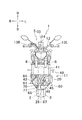
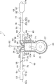
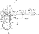
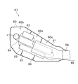
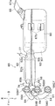
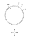
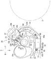
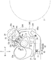
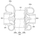
- FIG. 1 is a right side view of a motorcycle according to a first embodiment. It is the II-II sectional view taken on the line of FIG. It is a right view of a part of an engine unit. It is a front view of a part of an engine unit. It is a partial schematic diagram of an engine unit. It is a partial schematic diagram of an engine unit. It is sectional drawing of a muffler part. It is a top view of an exhaust apparatus.
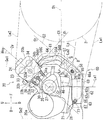
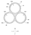
- FIG. 4 is a cross-sectional view taken along line AA in FIG. 3.
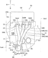
- FIG. 4 is a sectional view taken along line BB in FIG. 3.
- FIG. 10 is a right side view of a part of an engine unit of a first modification.
- FIG. 10 is a right side view of a part of an engine unit of a second modification.
- FIG. 9 is a cross-sectional view of a turbocharger of Modification 2.
- FIG. 10 is a side view of a turbocharger of a second modification.
- FIG. 6 is a right side view of a motorcycle according to a second embodiment. It is a bottom view of an engine unit. It is a right view of a part of an engine unit. It is a bottom view of an engine body.
- It is a partial schematic diagram of an engine unit. It is a partial schematic diagram of an engine unit. It is the DD sectional view taken on the line of FIG. 15 and FIG. It is a right view of a part of a modified engine unit. It is sectional drawing of the upstream exhaust passage part of a modification.
- the front-rear direction is the front-rear direction of the vehicle as viewed from a rider seated on a seat 9 (described later) of the motorcycle 1.
- the left-right direction is the left-right direction of the vehicle when viewed from the rider seated on the seat 9.
- the vehicle left-right direction is the same as the vehicle width direction.
- the arrow F direction and the arrow B direction of each drawing represent the front and the rear
- the arrow L direction and the arrow R direction represent the left side and the right side
- the arrow U direction and the arrow D direction are Represents the top and bottom.
- the motorcycle 1 includes a front wheel portion 2, a rear wheel portion 3, and a vehicle body frame 4.
- the vehicle body frame 4 has a head pipe 4a at the front thereof.
- a steering shaft (not shown) is rotatably inserted into the head pipe 4a.
- the upper end portion of the steering shaft is connected to the handle unit 5.
- An upper end portion of a pair of front forks 6 is fixed to the handle unit 5.
- a lower end portion of the front fork 6 supports the front wheel portion 2.
- the front fork 6 is configured to absorb an impact in the vertical direction.
- the front wheel portion 2 is composed of one front wheel.
- the upper part of the front wheel part 2 is covered with a fender. This fender is not included in the front wheel portion 2.
- the handle unit 5 has one handle bar 12 extending in the left-right direction.
- Grips 13 ⁇ / b> L and 13 ⁇ / b> R are provided at the left and right ends of the handle bar 12.
- the right grip 13R is an accelerator grip that adjusts the output of the engine.
- a display device 14 is attached to the handle bar 12. Although illustration is omitted, the display device 14 displays the vehicle speed, the engine speed, and the like.
- the display device 14 is provided with a warning lamp.
- Various switches are provided on the handle bar 12.
- a pair of swing arms 7 are swingably supported on the body frame 4.
- the rear end portion of the swing arm 7 supports the rear wheel portion 3.
- the rear wheel portion 3 is composed of one rear wheel.
- One end of the rear suspension 8 is attached to a position behind the swing center of each swing arm 7.
- the other end of the rear suspension 8 is attached to the vehicle body frame 4.
- the rear suspension 8 is configured to absorb an impact in the vertical direction. 1 and 2 and FIG. 3 to be described later show a state in which the front fork 6 and the rear suspension 8 have the longest vertical lengths. That is, a state in which the vehicle body frame 4 is at the uppermost position with respect to the front wheel portion 2 and the rear wheel portion 3 is displayed.
- the vehicle body frame 4 supports the seat 9 and the fuel tank 10.
- the fuel tank 10 is disposed in front of the seat 9.
- the vehicle body frame 4 supports the engine unit 11.
- the engine unit 11 may be directly connected to the vehicle body frame 4 or indirectly connected thereto.
- the engine unit 11 is disposed below the fuel tank 10.
- the engine unit 11 is disposed below the upper end of the seat 9.
- the front wheel portion 2 is disposed in front of the engine unit 11.
- the rear wheel portion 3 is disposed behind the engine unit 11 when viewed in the left-right direction.
- the lateral width of the engine unit 11 is larger than the lateral width of the front wheel portion 2.
- the lateral width of the engine unit 11 is larger than the lateral width of the rear wheel portion 3.
- the width in the left-right direction is the maximum length in the left-right direction.
- the vehicle body frame 4 supports a battery (not shown).
- the battery supplies power to a control device (not shown) that controls the engine unit 11 and electronic devices such as various sensors.
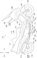
- the engine unit 11 includes an engine body 20, a water cooling device 40, and an exhaust device 60. Furthermore, as shown in FIG. 5, the engine unit 11 has an intake device 50. The engine body 20 is connected to the water cooling device 40, the intake device 50, and the exhaust device 60, respectively.
- the engine unit 11 is a three-cylinder engine having three cylinders.
- the engine unit 11 is a 4-stroke engine.
- a 4-stroke engine is an engine that repeats an intake stroke, a compression stroke, a combustion stroke (expansion stroke), and an exhaust stroke. The timing of the combustion stroke in the three cylinders is different.
- FIG. 5 shows only one of the three cylinders of the engine body 20 and omits the remaining two cylinders.
- the engine unit 11 is a water-cooled engine.
- the engine body 20 is configured to be cooled with cooling water.
- High-temperature cooling water that has absorbed the heat of the engine body 20 is supplied from the engine body 20 to the water cooling device 40.
- the water cooling device 40 lowers the temperature of the cooling water supplied from the engine body 20 and returns it to the engine body 20.
- the water cooling device 40 includes a radiator 41, a radiator fan (not shown), and a reservoir tank 42.
- the radiator 41 is disposed in front of the upper portion of the engine body 20.
- the radiator fan is disposed between the engine body 20 and the radiator 41.
- the reservoir tank 42 is disposed in front of the lower part of the engine body 20.
- the reservoir tank 42 is disposed in front of the right part of the engine body 20.
- the reservoir tank 42 may not be disposed in front of the right part of the engine body 20.
- the engine unit 11 has a water pump (not shown) for circulating cooling water.
- the water pump is provided inside the engine body
- the engine body 20 has a crankcase portion 20a and a cylinder portion 20b.
- the crankcase portion 20 a is provided at the lower part of the engine body 20.
- the cylinder part 20 b is provided on the upper part of the engine body 20.
- the cylinder part 20b is connected to the upper end part of the crankcase part 20a.
- the crankcase portion 20a has a crankcase 21 and an oil pan 26.
- the crankcase portion 20 a has a crankshaft 27 that is accommodated in the crankcase 21.
- the crankcase portion 20a includes a transmission, a clutch, a starter motor, and a generator. These are also accommodated in the crankcase 21.
- a central axis Cr of the crankshaft 27 is referred to as a crank axis Cr.
- the crank axis Cr is along the left-right direction. More specifically, the crank axis Cr is parallel to the left-right direction.
- the oil pan 26 is provided below the crankcase portion 20a.
- the oil pan 26 is connected to the lower end of the crankcase 21.
- the boundary between the oil pan 26 and the crankcase 21 is substantially straight.
- an extension of the boundary line between the crankcase 21 and the oil pan 26 is defined as a straight line Lp.
- the straight line Lp is along the front-rear direction.
- the straight line Lp is inclined so as to go downward as it goes forward.
- the straight line Lp may be orthogonal to a cylinder axis Cy described later.
- the right part of the oil pan 26 is recessed with respect to the left part of the oil pan 26.
- the right part of the oil pan 26 is located above the left part of the oil pan 26.
- a part of the exhaust device 60 is disposed inside the recess of the oil pan 26.
- Lubricating oil is stored in the oil pan 26.
- the crankcase part 20 a has an oil pump (not shown) that sucks up the lubricating oil stored in the oil pan 26.
- an oil filter 45 and an oil cooler 46 are provided at the front of the crankcase portion 20a.
- the oil cooler 46 is disposed substantially at the center in the left-right direction of the crankcase portion 20a.
- the oil filter 45 is disposed on the left side of the oil cooler 46.
- a plane passing through the center in the left-right direction of the front wheel portion 2 and the rear wheel portion 3 is defined as C0.
- the center in the left-right direction of the front wheel portion 2 and the rear wheel portion 3 is also the center in the left-right direction of the motorcycle 1.
- the center in the left-right direction of the motorcycle 1 is referred to as the center C0 in the left-right direction of the motorcycle 1.
- the oil cooler 46 is disposed at a position overlapping the center C0 in the left-right direction of the motorcycle 1.
- the oil filter 45 is disposed to the left of the center C0 in the left-right direction of the motorcycle 1. As shown in FIG. 3, the oil cooler 46 projects forward from the front surface of the crankcase 21. Similar to the oil cooler 46, the oil filter 45 also projects forward from the front surface of the crankcase 21.
- the oil filter 45 has a built-in filter main body (not shown). The filter body removes foreign substances contained in the lubricating oil.
- the oil filter 45 is detachably attached to the crankcase 21 so that the filter body can be replaced.
- the cylinder portion 20 b includes a cylinder body 22, a cylinder head 23, and a head cover 24.
- the cylinder body 22 is connected to the upper end portion of the crankcase 21.
- the cylinder head 23 is connected to the upper end portion of the cylinder body 22.
- the head cover 24 is connected to the upper end portion of the cylinder head 23.
- the cylinder body 22 is formed with a cylinder hole 22a.
- Three cylinder holes 22 a are formed in the cylinder body 22.
- the three cylinder holes 22a are adjacent to each other in the left-right direction.
- a piston 28 is slidably accommodated in each cylinder hole 22a.
- the three pistons 28 are connected to one crankshaft 27 via three connecting rods 29.
- a cooling passage 22b through which cooling water flows is formed.
- the central axis Cy of the cylinder hole 22a is referred to as a cylinder axis Cy.
- the three cylinder axes Cy are parallel. When viewed in the left-right direction, the three cylinder axes Cy coincide. As shown in FIG. 3, the cylinder axis Cy does not intersect with the crank axis Cr. Note that the cylinder axis Cy may intersect the crank axis Cr.
- the cylinder axis Cy is along the vertical direction. When viewed in the left-right direction, the cylinder axis Cy is inclined in the front-rear direction with respect to the up-down direction.
- the cylinder axis Cy is inclined such that the cylinder portion 20b is inclined forward. That is, the cylinder axis Cy is inclined so as to go forward as it goes upward.
- the tilt angle of the cylinder axis Cy relative to the vertical direction is defined as a tilt angle ⁇ cy.
- the inclination angle ⁇ cy is not limited to the angle shown in FIG.
- the inclination angle ⁇ cy is not less than 0 degrees and not more than 45 degrees.
- a combustion chamber 30 is formed in the cylinder portion 20b.
- Three combustion chambers 30 are formed in the cylinder portion 20b.
- the three combustion chambers 30 are adjacent to each other in the left-right direction.
- Each combustion chamber 30 is formed by the lower surface of the cylinder head 23, the cylinder hole 22 a, and the upper surface of the piston 28. That is, a part of the combustion chamber 30 is partitioned by the inner surface of the cylinder hole 22a.
- a straight line passing through the crank axis Cr and parallel to the vertical direction as seen in the left-right direction is defined as a straight line La1.
- the three combustion chambers 30 are disposed in front of the straight line La1. That is, when viewed in the left-right direction, the three combustion chambers 30 are disposed in front of the crank axis Cr.
- the tip of the spark plug 31 is disposed in the combustion chamber 30.
- the tip of the spark plug 31 generates a spark discharge.
- the air-fuel mixture in the combustion chamber 30 is ignited.
- the air-fuel mixture is an air-fuel mixture.
- the spark plug 31 is connected to the ignition coil 32.
- the ignition coil 32 stores electric power for causing spark discharge of the spark plug 31.
- the ignition plug 31 and the ignition coil 32 constitute an ignition device.
- an internal intake passage portion 33 and an internal exhaust passage portion 34 are formed.
- path part means the structure which forms a path
- the path means a space through which gas or the like passes.
- the internal intake passage portion 33 is connected to the combustion chamber 30.
- the internal intake passage portion 33 is provided for each combustion chamber 30.
- the internal exhaust passage portion 34 is connected to the combustion chamber 30.
- the internal exhaust passage portion 34 is provided for each combustion chamber 30.
- the internal intake passage portion 33 is provided for introducing air into the combustion chamber 30.
- the internal exhaust passage portion 34 is provided to exhaust the exhaust gas generated in the combustion chamber 30 from the combustion chamber 30.
- the combustion chamber intake port 33a and the combustion chamber exhaust port 34a are formed on the surface defining the combustion chamber 30 of the cylinder head 23.
- the combustion chamber intake port 33 a is formed at the downstream end of the internal intake passage portion 33.
- the combustion chamber exhaust port 34 a is formed at the upstream end of the internal exhaust passage portion 34.
- An intake port 33 b and an exhaust port 34 b are formed on the outer surface of the cylinder head 23.
- the intake port 33 b is formed at the upstream end of the internal intake passage portion 33.
- the exhaust port 34 b is formed at the downstream end of the internal exhaust passage portion 34.
- the number of combustion chamber intake ports 33a provided for one combustion chamber 30 may be one or two or more. For each combustion chamber 30, only one intake port 33b is provided.
- the internal intake passage portion 33 is formed in a bifurcated shape.
- the number of combustion chamber exhaust ports 34 a provided for one combustion chamber 30 may be one or two or more.
- only one exhaust port 34b is provided.
- the air inlet 33 b is formed on the front surface of the cylinder head 23.
- the exhaust port 34 b is formed on the front surface of the cylinder head 23.
- the three exhaust ports 34b are adjacent along the left-right direction.
- an intake valve 37 that opens and closes the combustion chamber intake port 33 a is disposed in the internal intake passage portion 33.
- One intake valve 37 is provided for each combustion chamber intake port 33a.
- An exhaust valve 38 that opens and closes the combustion chamber exhaust port 34 a is disposed in the internal exhaust passage portion 34.
- One exhaust valve 38 is provided for each combustion chamber exhaust port 34a.
- the intake valve 37 and the exhaust valve 38 are driven by a valve gear (not shown) housed in the cylinder head 23.
- the valve gear operates in conjunction with the crankshaft 27.
- the valve operating mechanism may have a variable valve timing device.
- a known variable valve timing device is applied.
- the variable valve timing device is configured to change the opening / closing timing of the intake valve and / or the exhaust valve.
- the engine main body 20 has an injector 54.
- the injector 54 is a fuel supply device that supplies fuel to the combustion chamber 30.
- One injector 54 is provided for each combustion chamber 30.
- the injector 54 is arranged so as to inject fuel in the internal intake passage portion 33.
- the injector 54 is connected to the fuel tank 10.
- a fuel pump (not shown) is arranged inside the fuel tank 10. The fuel pump pumps the fuel in the fuel tank 10 toward the injector 54.
- the injector 54 may be arranged to inject fuel in the combustion chamber 30. Further, the injector 54 may be arranged so as to inject fuel in a branch intake passage portion 51 described later of the intake device 50.
- the engine body 20 may include a carburetor instead of the injector 54 as a fuel supply device. The carburetor supplies fuel into the combustion chamber 30 using the negative pressure of the combustion chamber 30.
- the engine body 20 has an engine rotation speed sensor 71 and an engine temperature sensor 72.
- the engine rotation speed sensor 71 detects the rotation speed of the crankshaft 27, that is, the engine rotation speed.
- the engine temperature sensor 72 detects the temperature of the engine body 20. In the present embodiment, the engine temperature sensor 72 indirectly detects the temperature of the cylinder body 22 by detecting the temperature of the cooling water in the cooling passage 22b. The engine temperature sensor 72 may directly detect the temperature of the cylinder body 22.
- the intake device 50 has one intake passage portion 52 and three branched intake passage portions 51.
- the intake passage 52 has an air inlet 52a facing the atmosphere.
- the air inlet 52 a is formed at the upstream end of the intake passage portion 52.
- the intake passage 52 is provided with an air cleaner 53 for purifying air.
- the downstream end of the intake passage portion 52 is connected to the upstream ends of the three branched intake passage portions 51.
- the downstream ends of the three branch intake passage portions 51 are respectively connected to three intake ports 33 b formed on the rear surface of the cylinder head 23.
- the air inlet 52a sucks air from the atmosphere.
- the air flowing into the intake passage portion 52 from the air intake port 52 a is supplied to the engine body 20 through the three branched intake passage portions 51.
- a throttle valve 55 is disposed in the branch intake passage portion 51.
- One throttle valve 55 is provided for each combustion chamber 30.
- the opening degree of the throttle valve 55 is changed by the rider turning the accelerator grip 13R.
- the branch intake passage section 51 is provided with a throttle opening sensor (throttle position sensor) 73, an intake pressure sensor 74, and an intake air temperature sensor 75.
- the throttle opening sensor 73 outputs a signal representing the throttle opening by detecting the position of the throttle valve 55.
- the throttle opening is the opening of the throttle valve 55.
- the intake pressure sensor 74 detects the internal pressure of the branch intake passage portion 51.
- the intake air temperature sensor 75 detects the temperature of the air in the branch intake passage portion 51.
- the exhaust device 60 includes an upstream exhaust passage portion 61, a catalyst portion 62, and a downstream collective exhaust passage portion 63.
- upstream and downstream in the exhaust gas flow direction in the exhaust device 60 and the internal exhaust passage portion 34 are simply referred to as upstream and downstream.
- the upstream exhaust passage portion 61 includes three independent exhaust passage portions 64 and an upstream collective exhaust passage portion 65.
- One independent exhaust passage portion 64 is provided for each combustion chamber 30.
- the downstream collective exhaust passage portion 63 includes a downstream exhaust passage portion 66 and a muffler portion 67.
- the upstream ends of the three independent exhaust passage portions 64 are respectively connected to three exhaust ports 34 b formed on the front surface of the cylinder head 23.
- the downstream ends of the three independent exhaust passage portions 64 are connected to the upstream ends of the upstream collective exhaust passage portion 65.
- the upstream collective exhaust passage portion 65 collects (combines) the exhaust gas discharged from the three independent exhaust passage portions 64.
- the downstream end of the upstream collective exhaust passage portion 65 is connected to the upstream end of the catalyst portion 62.
- the catalyst unit 62 includes a main catalyst 62a that purifies exhaust gas.
- the downstream end of the catalyst portion 62 is connected to the upstream end of the downstream exhaust passage portion 66.
- the downstream end of the downstream exhaust passage portion 66 is connected to the upstream end of the muffler portion 67.
- the muffler part 67 has an atmospheric discharge port 67a facing the atmosphere.
- the exhaust gas discharged from the three exhaust ports 34 b of the engine body 20 passes through the upstream exhaust passage portion 61 and flows into the catalyst portion 62.
- the exhaust gas is purified by passing through the main catalyst 62a and then discharged from the atmospheric discharge port 67a through the downstream collective exhaust passage portion 63.
- the independent exhaust passage portion 64 corresponds to the independent exhaust passage portion in the present invention.
- the passage portion that combines the internal exhaust passage portion 34 and the independent exhaust passage portion 64 is referred to as an independent exhaust passage portion 68.
- One independent exhaust passage 68 is provided for each combustion chamber 30.
- a path from the combustion chamber 30 to the atmospheric discharge port 67a is referred to as an exhaust path 69.
- the engine unit 11 has three exhaust paths 69.
- the exhaust path 69 is a space through which exhaust gas discharged from one combustion chamber 30 passes.
- the exhaust passage 69 is formed by the independent exhaust passage portion 68, the upstream collective exhaust passage portion 65, the catalyst portion 62, and the downstream collective exhaust passage portion 63.
- the exhaust passage 69 is formed by the internal exhaust passage portion 34, the upstream exhaust passage portion 61, the catalyst portion 62, and the downstream collective exhaust passage portion 63.
- the exhaust device 60 includes first to third exhaust pipes 56A, 56B, 56C, a collective member 57, a collective exhaust pipe 58, and a muffler portion 67.
- the first to third exhaust pipes 56A, 56B, and 56C are arranged in this order from right to left.
- the upstream ends of the first to third exhaust pipes 56A, 56B, and 56C are connected to the three exhaust ports 34b of the engine body 20, respectively.
- the first to third exhaust pipes 56A, 56B, and 56C are circular pipes.
- Mounting flange portions 56Af, 56Bf, and 56Cf are provided in the vicinity of the upstream ends of the first to third exhaust pipes 56A, 56B, and 56C.
- the mounting flange portions 56Af, 56Bf, and 56Cf are formed in a plate shape.
- Bolt holes into which bolts are inserted are formed in the mounting flange portions 56Af, 56Bf, and 56Cf.
- a portion of the first exhaust pipe 56 ⁇ / b> A upstream from the mounting flange portion 56 ⁇ / b> Af is inserted inside the internal exhaust passage portion 34. The same applies to the second exhaust pipe 56B and the third exhaust pipe 56C.
- the mounting flange portions 56Af, 56Bf, and 56Cf are in contact with the outer surface of the engine body 20.
- the mounting flange portions 56Af, 56Bf, and 56Cf are fixed to the outer surface of the engine body 20 by bolts.
- the downstream ends of the first to third exhaust pipes 56A, 56B, and 56C are connected to the collective member 57.
- the interior of the collective member 57 is divided into three spaces 57A, 57B, and 57C.
- the end portions of the first to third exhaust pipes 56A, 56B, and 56C are fitted into the three spaces 57A, 57B, and 57C, respectively.
- the downstream ends of the three spaces 57A, 57B, 57C are downstream from the downstream ends of the first to third exhaust pipes 56A, 56B, 56C. Further, as shown in FIG.
- the interior of the assembly member 57 has one space 57 ⁇ / b> D in a cross section orthogonal to the flow direction of the exhaust gas at the lower part of the assembly member 57.
- the total volume of the internal space of the assembly member 57 decreases toward the downstream.
- those indicated by solid lines indicate directions parallel to the paper surface, and those indicated by broken lines indicate directions not parallel to the paper surface.
- the assembly member 57 includes a wall portion that forms a space 57A, a wall portion that forms a space 57B, a wall portion that forms a space 57C, and a wall portion that forms a space 57D.
- An independent exhaust passage portion 64A (see FIG. 4) is formed by the first exhaust pipe 56A and the wall portion forming the space 57A of the collective member 57. However, the independent exhaust passage portion 64A does not include a portion upstream from the mounting flange portion 56Af of the first exhaust pipe 56A.
- An independent exhaust passage portion 64B (see FIG. 4) is formed by the second exhaust pipe 56B and the wall portion forming the space 57B of the collective member 57.
- the independent exhaust passage portion 64B does not include a portion upstream of the mounting flange portion 56Bf of the second exhaust pipe 56B.
- An independent exhaust passage portion 64C (see FIG. 4) is formed by the third exhaust pipe 56C and the wall portion forming the space 57C of the collective member 57.
- the independent exhaust passage portion 64C does not include a portion upstream from the mounting flange portion 56Cf of the third exhaust pipe 56C.
- the independent exhaust passage portion 64 is a general term for the independent exhaust passage portions 64A, 64B, and 64C.
- the downstream end of the collecting member 57 is connected to the collecting exhaust pipe 58.
- the collective exhaust pipe 58 is a pipe having a substantially circular cross section. As shown in FIG. 8, the collective exhaust pipe 58 is formed by welding two left and right parts.
- a main catalyst 62 a is disposed inside the collective exhaust pipe 58.
- a portion of the collective exhaust pipe 58 where the main catalyst 62a is disposed is referred to as a cylindrical portion 62b.
- the catalyst part 62 includes a cylindrical part 62b and a main catalyst 62a.
- the upstream collective exhaust passage portion 65 is formed by a part forming the space 57D of the collective member 57 and a part upstream of the main catalyst 62a of the collective exhaust pipe 58.
- the downstream end of the collective exhaust pipe 58 is connected to the muffler part 67. Specifically, the downstream end of the collective exhaust pipe 58 is disposed in the muffler portion 67.
- the downstream exhaust passage portion 66 is formed by a portion downstream of the main catalyst 62 a of the collective exhaust pipe 58. However, the downstream exhaust passage portion 66 does not include a portion of the collective exhaust pipe 58 that is disposed inside the muffler portion 67.
- the three independent exhaust passage parts 64 each have a plurality of bent parts.
- the three independent exhaust passage portions 64 have a bent portion so that a difference in path length between the three independent exhaust passage portions 64 is reduced. At least one bent portion of one independent exhaust passage portion 64 is bent when viewed in the left-right direction. At least one bent portion included in one independent exhaust passage portion 64 is bent when viewed in the front-rear direction.
- the flow direction of the exhaust gas at the upstream ends of the three independent exhaust passage portions 64 is parallel.
- the flow direction of the exhaust gas at the upstream ends of the three independent exhaust passage portions 64 is a front obliquely downward direction.
- An axis passing through the center of the upstream end of the independent exhaust passage portion 64A including a part of the first exhaust pipe 56A when viewed in the left-right direction is defined as a center axis C1.
- the direction of the central axis C1 is the flow direction of the exhaust gas at the upstream end of the independent exhaust passage portion 64A.
- the inclination angle of the central axis C1 with respect to the front-rear direction is defined as an inclination angle ⁇ 1 .
- the inclination angle ⁇ 1 is not limited to the angle shown in FIG.
- the inclination angle ⁇ 1 is not less than 0 degrees and not more than 45 degrees. Therefore, the central axis C1 is along the front-rear direction. That is, when viewed in the left-right direction, the flow direction of the exhaust gas at the upstream ends of the three independent exhaust passage portions 64 is a direction along the front-rear direction. Further, when viewed in the front-rear direction, the flow direction of the exhaust gas at the upstream ends of the three independent exhaust passage portions 64 is substantially parallel to the vertical direction. Therefore, the flow direction of the exhaust gas at the upstream ends of the three independent exhaust passage portions 64 is a direction along the front-rear direction.
- the flow direction of the exhaust gas at the downstream ends of the three independent exhaust passage portions 64 is a rear obliquely downward direction.
- An axis passing through the center of the downstream end of the independent exhaust passage portion 64A including a part of the first exhaust pipe 56A when viewed in the left-right direction is defined as a center axis C2.
- the inclination angle ⁇ 2 is not limited to the angle shown in FIG.
- the inclination angle ⁇ 2 is not less than 0 degrees and not more than 45 degrees. Therefore, the central axis C2 is along the vertical direction.
- the flow direction of the exhaust gas at the downstream ends of the three independent exhaust passage portions 64 is a direction along the vertical direction. Further, when viewed in the front-rear direction, the flow direction of the exhaust gas at the downstream ends of the three independent exhaust passage portions 64 is substantially parallel to the vertical direction. Therefore, the flow direction of the exhaust gas at the downstream ends of the three independent exhaust passage portions 64 is a direction along the vertical direction.
- the upstream collecting exhaust passage portion 65 has a bent portion 65a.
- the bent portion 65a When viewed in the left-right direction, the bent portion 65a is bent.
- the bent portion 65 a is formed in the collective exhaust pipe 58.
- the bent portion 65 a is formed in the vicinity of the downstream end of the upstream collective exhaust passage portion 65.
- the flow direction of the exhaust gas in the portion upstream of the bent portion 65a of the upstream collective exhaust passage portion 65 is substantially parallel to the central axis C2.
- the flow direction of the exhaust gas in a portion upstream of the bent portion 65a of the upstream collective exhaust passage portion 65 is substantially parallel to the vertical direction. Therefore, the flow direction of the exhaust gas in the portion upstream of the bent portion 65a of the upstream collective exhaust passage portion 65 is along the vertical direction.
- the central axis of the catalyst part 62 is defined as a central axis C3.
- the axis passing through the center of the portion downstream of the bent portion 65a of the upstream exhaust passage portion 61 is coaxial with the center axis C3.
- the central axis C3 is along the front-rear direction.
- the tilt angle ⁇ 3 (not shown) is the tilt angle of the central axis C3 with respect to the front-rear direction when viewed in the left-right direction.
- the inclination angle ⁇ 3 is approximately 0 degrees. That is, when viewed in the left-right direction, the central axis C3 is substantially parallel to the front-rear direction.
- the tilt angle ⁇ 3 may be greater than 0 degrees.
- the inclination angle ⁇ 3 is preferably 0 degree or greater and 45 degrees or less.
- the central axis C3 is substantially parallel to the front-rear direction when viewed in the vertical direction. Therefore, the central axis C3 is along the front-rear direction. That is, the flow direction of the exhaust gas in the portion downstream of the bent portion 65a of the upstream collective exhaust passage portion 65 is a direction along the front-rear direction.
- the bent portion 65a changes the flow direction of the exhaust gas flowing through the bent portion 65a from the direction along the vertical direction to the direction along the front-rear direction. More specifically, the bent portion 65a changes the flow direction of the exhaust gas flowing through the bent portion 65a from the direction along the lower direction to the direction along the rear direction.
- the central axis C3 of the catalyst portion 62 is along the front-rear direction. That is, the flow direction of the exhaust gas flowing inside the catalyst unit 62 is a direction along the front-rear direction. More specifically, the flow direction of the exhaust gas flowing inside the catalyst unit 62 is a direction along the rear direction.
- An axis passing through the center of the downstream exhaust passage portion 66 is coaxial with the center axis C3. Therefore, the flow direction of the exhaust gas flowing inside the downstream exhaust passage portion 66 is a direction along the front-rear direction. More specifically, the flow direction of the exhaust gas flowing inside the downstream exhaust passage portion 66 is a direction along the rear direction.
- the vicinity of the downstream end of the upstream collective exhaust passage portion 65 is formed in a tapered shape so that its diameter increases toward the downstream. This taper part is formed in the bending part 65a.
- a concave portion 65 b is formed in the vicinity of the downstream end of the upstream collective exhaust passage portion 65.
- a part of the recess 65b is formed in the bent portion 65a.
- a part of the recess 65b is formed upstream of the bent portion 65a.
- the area of the cross section orthogonal to the flow direction of the exhaust gas in the vicinity of the downstream end of the upstream collective exhaust passage section 65 is defined as a cross-sectional area A1 (not shown).
- a cross section orthogonal to the flow direction of the exhaust gas in the catalyst portion 62 is defined as a cross sectional area A2 (not shown).
- the cross-sectional area A1 is smaller than the cross-sectional area A2.
- the downstream exhaust passage portion 66 is formed in a tapered shape so that its diameter decreases toward the downstream.
- the area of the cross section orthogonal to the flow direction of the exhaust gas in the vicinity of the upstream end of the downstream exhaust passage section 66 is defined as a cross sectional area A3 (not shown).
- the cross-sectional area A3 is smaller than the cross-sectional area A2.
- the lower end portions of the three independent exhaust passage portions 64 overlap with the oil cooler 46.
- the three independent exhaust passage portions 64 do not overlap the oil filter 45.
- the lower ends of the three independent exhaust passage portions 64 are arranged to the right of the oil filter 45.
- the exhaust device 60 and the oil filter 45 are viewed from the front, the oil filter 45 is exposed. Therefore, the oil filter 45 can be easily removed from the engine body 20. Therefore, the oil filter 45 can be easily replaced. Note that a part of the exhaust device 60 may overlap the oil filter 45 when viewed in the front-rear direction.
- a part of the upstream collective exhaust passage portion 65 is disposed in front of the engine body 20.
- a part of the upstream collecting exhaust passage portion 65 overlaps with the engine body 20 when viewed in the front-rear direction. That is, a part of the upstream collective exhaust passage portion 65 is disposed in front of the engine body 20. More specifically, a part of the upstream collective exhaust passage portion 65 is disposed in front of the crankcase portion 20a.
- the upstream collective exhaust passage 65 is disposed below the crank axis Cr.
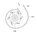
- the muffler unit 67 is a device that reduces noise caused by exhaust gas. As shown in FIG. 8, a bracket 67 b is provided on the upper surface of the muffler portion 67. The bracket 67b is attached to the vehicle body frame 4. That is, the muffler part 67 is supported by the vehicle body frame 4.
- the muffler portion 67 includes an outer cylinder 80 and a tail pipe 85.
- the outer cylinder 80 is formed by welding two left and right parts.
- the muffler portion 67 has four pipes 81 to 84 accommodated in the outer cylinder 80.
- the inside of the outer cylinder 80 is partitioned into three expansion chambers 80a, 80b, and 80c by two separators 86 and 87.
- the first pipe 81 is connected to the downstream end of the collective exhaust pipe 58.
- a portion of the collective exhaust pipe 58 inside the outer cylinder 80 is included in the muffler portion 67.
- the first pipe 81 connects the collective exhaust pipe 58 and the central first expansion chamber 80a among the three expansion chambers.
- the second pipe 82 communicates the first expansion chamber 80a with the second expansion chamber 80b behind the first expansion chamber 80a.
- the third pipe 83 communicates the second expansion chamber 80b and the third expansion chamber 80c in front of the first expansion chamber 80a.
- the fourth pipe 84 makes the third expansion chamber 80c communicate with the tail pipe 85 (see FIG. 8).
- the fourth pipe 84 is bent in the second expansion chamber 80b.
- the tail pipe 85 penetrates the right wall of the second expansion chamber 80b.
- the tail pipe 85 is connected to the fourth pipe 84 in the second expansion chamber 80b.
- the opening at the downstream end of the tail pipe 85 is an atmospheric discharge port 67a.
- the exhaust gas discharged from the collective exhaust pipe 58 includes the first pipe 81, the first expansion chamber 80a, the second pipe 82, the second expansion chamber 80b, the third pipe 83, the third expansion chamber 80c, the fourth pipe 84, and the tail.
- a sound absorbing material such as glass wool may be disposed, but it may not be disposed.
- the internal structure of the muffler part 67 is not limited to the structure shown in FIG.
- the catalyst part 62 has a main catalyst 62a and a cylindrical part 62b.
- the cylindrical portion 62 b is connected to the downstream end of the upstream collective exhaust passage portion 65 and the upstream end of the downstream exhaust passage portion 66.
- the cylindrical portion 62b may be integrally formed with a part of the upstream collective exhaust passage portion 65.
- the cylindrical portion 62b may be integrally formed with a part of the downstream exhaust passage portion 66.
- the exhaust device 60 has no catalyst other than the main catalyst 62a.
- the main catalyst 62a most purifies the exhaust gas in the plurality of exhaust paths 69 (see FIG. 5).
- the main catalyst 62a is formed in a cylindrical shape.
- the main catalyst 62a has a porous structure.
- the porous structure means a structure in which a plurality of holes penetrating in the exhaust gas flow direction are formed.
- the main catalyst 62a is a three-way catalyst.
- the three-way catalyst is removed by oxidizing or reducing three substances of hydrocarbon (HC), carbon monoxide (CO), and nitrogen oxide (NOx) in the exhaust gas.
- the three-way catalyst is one type of redox catalyst.
- the main catalyst 62a may be a catalyst that removes any one or two of hydrocarbon, carbon monoxide, and nitrogen oxide.
- the main catalyst 62a may not be a redox catalyst.
- the main catalyst may be an oxidation catalyst that removes harmful substances only by oxidation.
- the main catalyst may be a reduction catalyst that removes harmful substances only by reduction.
- the main catalyst 62a has a base material and a catalytic material attached to the surface of the base material.
- the catalytic material has a support and a noble metal.
- the carrier has a function of attaching a noble metal to the substrate.
- the noble metal has a function of purifying exhaust gas. Examples of the noble metal include platinum, palladium, and rhodium that remove hydrocarbons, carbon monoxide, and nitrogen oxides, respectively.
- the main catalyst 62a may be a metal base catalyst or a ceramic base catalyst.
- the metal base catalyst is a catalyst whose base is made of metal.
- the ceramic base catalyst is a catalyst whose base is made of ceramic.
- the base material of the metal base catalyst is formed, for example, by alternately stacking and winding metal corrugated plates and metal flat plates.
- the base material of the ceramic base catalyst is, for example, a honeycomb structure.
- the central axis C3 of the catalyst part 62 is coaxial with the central axis of the main catalyst 62a.
- the central axis C3 of the catalyst part 62 is the central axis of the cylinder part 62b.
- the length of the catalyst portion 62 in the exhaust gas flow direction is the same as the length of the main catalyst 62a in the exhaust gas flow direction.
- the center of the upstream end of the main catalyst 62a and the center of the upstream end of the catalyst unit 62 are at the same position.
- the center of the downstream end of the main catalyst 62a and the center of the downstream end of the catalyst portion 62 are at the same position.
- the length of the catalyst portion 62 in the exhaust gas flow direction is defined as a length Dc1 (not shown).
- the maximum length in the direction orthogonal to the flow direction of the exhaust gas in the catalyst unit 62 is defined as a length Dc2 (not shown).
- the length Dc1 is longer than the length Dc2.
- a plane passing through the foremost end of the crankcase portion 20a and orthogonal to the front-rear direction is defined as a plane Se1.
- a plane passing through the rearmost end of the crankcase portion 20a and orthogonal to the front-rear direction is defined as a plane Se2.
- the catalyst unit 62 is disposed between the plane Se1 and the plane Se2.
- a part of the catalyst portion 62 is disposed below the crankcase portion 20a when viewed in the left-right direction. Note that the entire catalyst portion 62 may be disposed below the crankcase portion 20a when viewed in the left-right direction.
- a plane that passes through the leftmost end of the engine body 20 and is orthogonal to the left-right direction is defined as a plane Se3.
- the plane Se3 passes through the leftmost end of the crankcase portion 20a.
- a plane passing through the rightmost end of the engine body 20 and orthogonal to the left-right direction is defined as a plane Se4.
- the plane Se4 passes through the rightmost end of the crankcase portion 20a.
- the catalyst unit 62 is disposed between the plane Se3 and the plane Se4. Although not shown, the catalyst part 62 entirely overlaps the crankcase part 20a when viewed in the vertical direction.
- the catalyst part 62 is disposed below the crankcase part 20a.
- a part of the catalyst unit 62 is disposed below a part of the oil pan 26. Only a part of the catalyst part 62 may be disposed below the crankcase part 20a. It is preferable that at least a part of the catalyst portion 62 is disposed below the crankcase portion 20a.
- a part of the catalyst portion 62 is disposed in front of the straight line La1. That is, a part of the catalyst unit 62 is disposed in front of the crank axis Cr.
- the whole catalyst part 62 may be arrange
- the catalyst unit 62 When viewed in the left-right direction, the catalyst unit 62 is disposed in front of the cylinder axis Cy. Note that only a part of the catalyst unit 62 may be disposed in front of the cylinder axis Cy. It is preferable that at least a part of the catalyst unit 62 is disposed in front of the cylinder axis Cy.
- a straight line La2 is a straight line perpendicular to the cylinder axis Cy and passing through the crank axis Cr when viewed in the left-right direction.
- the entire catalyst unit 62 When viewed in the left-right direction, the entire catalyst unit 62 is disposed behind (below) the straight line La2. Note that only a part of the catalyst portion 62 may be disposed behind the straight line La2 when viewed in the left-right direction. As viewed in the left-right direction, it is preferable that at least a part of the catalyst portion 62 is disposed behind the straight line La2.
- the entire catalyst portion 62 When viewed in the left-right direction, the entire catalyst portion 62 is disposed below (behind) the straight line Lp.
- the straight line Lp is an extension of the boundary line between the crankcase 21 and the oil pan 26 when the engine unit 11 is viewed in the left-right direction. Only a part of the catalyst unit 62 may be disposed below the straight line Lp. It is preferable that at least a part of the catalyst portion 62 is disposed below the straight line Lp.
- the line segment Lw ⁇ b> 1 that is arranged at the lowest position among the line segments connecting the point on the contour line of the engine body 20 and the point on the contour line of the front wheel portion 2 when viewed in the left-right direction
- the line segment Lw1 is a line segment that connects the lowermost end of the engine body 20 and the vicinity of the lowermost end of the front wheel portion 2.
- a part of the catalyst portion 62 is disposed above the line segment Lw1 and its extension line.
- the line segment arranged at the uppermost position among the line segments connecting the points on the contour line of the engine body 20 and the points on the contour line of the front wheel portion 2 when viewed in the left-right direction is defined as a line segment Lw2.
- the line segment Lw2 is a line segment that connects the uppermost end of the engine body 20 and the uppermost end of the front wheel portion 2 or the vicinity thereof.
- a part of the catalyst unit 62 is disposed in a rectangular area having two lines Lw1 and Lw2.
- the quadrangle having the line segment Lw1 and the line segment Lw2 as two sides is a quadrangle having vertices at both ends of the line segment Lw1 and both ends of the line segment Lw2.
- a part of the catalyst unit 62 is disposed within the above-described rectangular region and does not overlap the engine body 20.
- a part of the catalyst portion 62 is disposed between the engine body 20 and the front wheel portion 2.
- the entire catalyst portion 62 may be disposed between the engine body 20 and the front wheel portion 2 when viewed in the left-right direction. It is preferable that at least a part of the catalyst part 62 is disposed between the engine body 20 and the front wheel part 2 when viewed in the left-right direction. Further, when viewed in the left-right direction, the entire catalyst unit 62 may be disposed above the line segment Lw1 and its extension line.
- the relative position of the engine unit 11 with respect to the front wheel portion 2 changes.
- the catalyst portion 62 When at least a part of the catalyst portion 62 is disposed between the engine body 20 and the front wheel portion 2 when viewed in the left-right direction, it is disposed regardless of the position of the engine unit 11 with respect to the front wheel portion 2. It does not mean that When at least a part of the catalyst portion 62 is disposed between the engine body 20 and the front wheel portion 2 when viewed in the left-right direction, it is disposed when the engine unit 11 is in any position with respect to the front wheel portion 2. It should be.
- a horizontal plane passing through the center of the front wheel portion 2 is defined as a horizontal plane Sh.
- the catalyst unit 62 is disposed below the horizontal plane Sh.
- the catalyst portion 62 is disposed below the horizontal plane Sh as long as the engine unit 11 is located at any position with respect to the front wheel portion 2.
- the catalyst unit 62 is disposed on the right side of the motorcycle 1.
- the center of the upstream end and the center of the downstream end of the catalyst unit 62 are not arranged on the center C0 in the left-right direction of the motorcycle 1.
- the center of the upstream end and the center of the downstream end of the catalyst unit 62 are located to the right of the center C0 in the left-right direction of the motorcycle 1.
- the catalyst unit 62 is disposed to the right of the center C0 in the left-right direction of the motorcycle 1.
- a part of the catalyst unit 62 is disposed on the right side of the center C0 in the left-right direction of the motorcycle 1, and the remaining part of the catalyst unit 62 is on the left side of the center C0 in the left-right direction of the motorcycle 1. It may be arranged.
- the average value of the path length from the combustion chamber 30 to the upstream end of the catalyst unit 62 in the three exhaust paths 69 is defined as a path length Da1.
- a path length from the downstream end of the catalyst unit 62 to the atmospheric discharge port 67a is defined as a path length Db1.
- the path length Da1 is shorter than the path length Db1.
- the average value of the path length from the exhaust port 34b to the upstream end of the catalyst unit 62 in the three exhaust paths 69 is defined as a path length Da2.
- a path length from the downstream end of the catalyst unit 62 to the upstream end of the muffler unit 67 is defined as a path length Db2.
- the path length Da1 is longer than the path length Db2.
- the path length Da2 is longer than the path length Db2.
- the path length Da2 may be shorter than the path length Db2.
- the path length Da1 may be shorter than the path length Db2.
- the path length in the expansion chamber of the muffler part 67 is defined as follows.
- the path length in the first expansion chamber 80a from the downstream end of the first pipe 81 to the upstream end of the second pipe 82 is taken as an example.
- This path length is the length of the path that connects the center of the downstream end of the first pipe 81 to the center of the upstream end of the second pipe 82 in the shortest distance. That is, the path length in the expansion chamber of the muffler portion 67 is the length of the path that connects the center of the inflow port of the expansion chamber to the center of the outflow port of the expansion chamber in the shortest distance.
- the exhaust device 60 includes an upstream oxygen sensor 76 and a downstream oxygen sensor 77.
- the upstream oxygen sensor 76 is provided in the upstream collecting exhaust passage portion 65.
- the upstream oxygen sensor 76 detects the oxygen concentration in the exhaust gas in the upstream collecting exhaust passage portion 65.
- the downstream oxygen sensor 77 is provided in the downstream exhaust passage portion 66.
- the downstream oxygen sensor 77 detects the oxygen concentration in the exhaust gas in the downstream exhaust passage portion 66. Note that the exhaust device 60 may not include the downstream oxygen sensor 77.
- the engine unit 11 has a control device (not shown) that controls the operation of the engine unit 11.
- the control device is connected to various sensors 71-77.
- the control device controls the operation of the engine unit 11 based on signals from the various sensors 71 to 77.
- the control device controls the fuel injection amount of the injector 54 based on signals from various sensors including the upstream oxygen sensor 76.
- the signal of the downstream oxygen sensor 77 may be used for controlling the fuel injection amount.
- the control device determines the purification capacity of the main catalyst 62a based on the signal from the downstream oxygen sensor 77.
- the control device may determine the purification capacity of the main catalyst 62a based on the signal from the upstream oxygen sensor 76 and the signal from the downstream oxygen sensor 77.
- the control device sends a signal to the display device 14 when it is determined that the purification capacity of the main catalyst 62a has dropped below a predetermined level. Then, a warning lamp (not shown) of the display device 14 is turned on. As a result, the rider can be urged to replace the main catalyst 62a. Further, the control device controls the discharge timing of the spark plug 31. Further, the control device controls energization to a starter motor (not shown), thereby controlling the start of the engine unit 11.
- the motorcycle 1 of the present embodiment described above has the following characteristics. At least a part of the catalyst portion 62 is disposed below the crankcase portion 20a.
- the catalyst unit 62 is disposed so that the flow direction of the exhaust gas flowing through the catalyst unit 62 is aligned with the horizontal direction.
- the direction along the horizontal direction is not limited to the direction parallel to the horizontal direction. Including a direction inclined within a range of ⁇ 45 ° with respect to the horizontal direction.
- at least a part of the upstream collective exhaust passage portion 65 is disposed in front of the engine body 20. Therefore, the path length of the upstream collective exhaust passage portion 65 can be made longer than when the upstream collective exhaust passage portion 65 is not disposed in front of the engine body 20.
- the exhaust gas is more easily diffused in the upstream collective exhaust passage portion 65.
- the upstream collective exhaust passage portion 65 has a bent portion 65a.
- the bent portion 65a changes the flow direction of the exhaust gas flowing through the bent portion 65a from the direction along the vertical direction to the direction along the horizontal direction.
- the exhaust gas is more easily diffused in the upstream collective exhaust passage portion 65.
- the exhaust gas easily diffuses in the upstream collective exhaust passage portion 65, the deviation of the exhaust gas passage position in the main catalyst 62a can be suppressed.
- the exhaust purification performance of the main catalyst 62a can be improved while maintaining the size of the main catalyst 62a as compared with the case where there is a bias. As a result, it is possible to suppress an increase in the size of the motorcycle 1 in the vertical direction while improving the exhaust purification performance of the main catalyst 62a.
- the engine body 20 is arranged such that a plurality of cylinder axes Cy are along the vertical direction. As described above, at least a part of the catalyst portion 62 is disposed below the crankcase portion 20a of the engine body 20. Therefore, the upstream collective exhaust passage portion 65 has a longer path length than the case where the engine body 20 is arranged so that the cylinder axis Cy is along the front-rear direction. Accordingly, the exhaust gas is more easily diffused in the upstream collective exhaust passage portion 65. Therefore, the deviation of the exhaust gas passage position in the main catalyst 62a can be further suppressed. Therefore, the exhaust purification performance of the main catalyst 62a can be improved while maintaining the size of the main catalyst 62a as compared with the case where there is a bias. As a result, it is possible to suppress an increase in the size of the motorcycle 1 in the vertical direction while improving the exhaust purification performance of the main catalyst 62a.
- At least a part of the catalyst unit 62 is disposed in front of the crank axis Cr. Therefore, the catalyst part 62 can be disposed more forward than the case where the entire catalyst part 62 is disposed behind the crank axis Cr. Therefore, the path length Da1 from the combustion chamber 30 to the catalyst unit 62 is shortened. Therefore, the temperature of the exhaust gas flowing into the main catalyst 62a becomes higher. Thereby, when the engine unit 11 is cold started, the time until the main catalyst 62a is activated from the inactive state is further shortened. As a result, the exhaust purification performance by the main catalyst 62a can be further improved.
- the upstream collective exhaust passage 65 has a longer path length than when the entire catalyst 62 is disposed in front of the straight line La2. Accordingly, the exhaust gas is more easily diffused in the upstream collective exhaust passage portion 65. Therefore, the deviation of the exhaust gas passage position in the main catalyst 62a can be further suppressed. Therefore, the exhaust purification performance of the main catalyst 62a can be improved while maintaining the size of the main catalyst 62a as compared with the case where there is a bias. As a result, it is possible to suppress an increase in the size of the motorcycle 1 in the vertical direction while improving the exhaust purification performance of the main catalyst 62a.
- FIG. 11 is a right side view of a part of the engine unit of Modification 1 of the first embodiment.
- the same components as those in the first embodiment are denoted by the same reference numerals, and detailed description thereof is omitted.
- the engine unit of the first modification has a downstream sub-catalyst 47D and an upstream sub-catalyst 47U.
- the upstream sub-catalyst 47U and the downstream sub-catalyst 47D may be collectively referred to as a sub-catalyst 47 (not shown).
- the upstream sub-catalyst 47U is disposed upstream of the catalyst unit 62.
- the upstream sub catalyst 47U is disposed in the upstream exhaust passage portion 61.
- the upstream sub-catalyst 47U is disposed in at least one of the plurality of independent exhaust passage portions 64.
- the upstream sub-catalyst 47U may be disposed in the upstream collective exhaust passage portion 65. Further, the upstream sub-catalyst 47U may be disposed in at least one of the plurality of internal exhaust passage portions 34.
- the upstream sub catalyst 47U is disposed upstream of the upstream oxygen sensor 76.
- the upstream sub catalyst 47U is disposed upstream of the bent portion 65a.
- the downstream sub-catalyst 47D is disposed downstream of the catalyst unit 62.
- the downstream sub-catalyst 47D is disposed in the downstream collective exhaust passage portion 63.
- the downstream sub-catalyst 47 ⁇ / b> D is disposed in the muffler portion 67.
- the downstream sub-catalyst 47D may be disposed in the downstream exhaust passage portion 66.
- the downstream sub-catalyst 47 ⁇ / b> D is disposed downstream of the downstream oxygen sensor 77.
- the sub catalyst 47 purifies the exhaust gas.
- the sub catalyst 47 has the same catalyst material as the main catalyst 62a.
- the sub catalyst 47 may have a porous structure like the main catalyst 62a.
- the sub catalyst 47 may not have a porous structure.
- An example of the subcatalyst 47 having no porous structure will be given.
- the sub-catalyst 47 is composed of only the catalyst material attached to the inner surface of the downstream collecting exhaust passage portion 63. In this case, the base material to which the catalyst material of the sub catalyst 47 is attached is the downstream collective exhaust passage portion 63. Another example of the sub-catalyst 47 having no porous structure will be given.
- the sub-catalyst 47 has a configuration in which a catalytic substance is attached to a plate-like base material.
- the cross-sectional shape orthogonal to the flow direction of the exhaust gas of the plate-like substrate is, for example, a circular shape, a C shape, or an S shape.
- the main catalyst 62a purifies the exhaust gas most in the plurality of exhaust passages 69. That is, the main catalyst 62 a purifies the exhaust gas discharged from the combustion chamber 30 in the plurality of exhaust passages 69 rather than the sub catalyst 47. In other words, the sub catalyst 47 has a lower contribution to purify the exhaust gas than the main catalyst 62a.
- the respective purification contributions of the main catalyst 62a, the upstream sub-catalyst 47U, and the downstream sub-catalyst 47D can be measured by the following method.
- the engine unit of the first modification is operated, and the concentration of harmful substances contained in the exhaust gas discharged from the atmospheric discharge port 67a in the warm-up state is measured.
- the warm-up state refers to a state where the temperature of the engine body 20 is sufficiently warmed.
- the exhaust gas measurement method shall be in accordance with European regulations.
- the downstream sub-catalyst 47D is removed from the engine unit of the first modification, and only the base material of the downstream sub-catalyst 47D is disposed instead.
- the engine unit in this state is referred to as a measurement engine unit A.
- the measurement engine unit A is operated to measure the concentration of harmful substances contained in the exhaust gas discharged from the atmospheric discharge port 67a in the warm-up state.
- the downstream sub-catalyst 47D may have a configuration in which a catalytic substance is directly attached to the inner surface of the downstream collecting exhaust passage portion 63.
- “disposing only the base material of the downstream sub-catalyst 47 ⁇ / b> D” means that the catalytic material is not attached to the inner surface of the downstream collecting exhaust passage portion 63.
- the main catalyst 62a is removed from the measurement engine unit A, and only the base material of the main catalyst 62a is disposed instead.
- the engine unit in this state is referred to as a measurement engine unit B.
- the measurement engine unit B is operated to measure the concentration of harmful substances contained in the exhaust gas discharged from the atmospheric discharge port 67a in the warm-up state.
- the upstream sub-catalyst 47U is removed from the measurement engine unit B, and instead, only the base material of the upstream sub-catalyst 47U is disposed.
- the engine unit in this state is referred to as a measurement engine unit C.
- the measurement engine unit C is operated to measure the concentration of harmful substances contained in the exhaust gas discharged from the atmospheric discharge port 67a in the warm-up state.
- the engine unit C for measurement does not have the main catalyst 62a and the sub catalyst 47.
- the measurement engine unit B includes an upstream sub-catalyst 47U and does not include the main catalyst 62a and the downstream sub-catalyst 47D.
- the measurement engine unit A has a main catalyst 62a and an upstream sub catalyst 47U, and does not have a downstream sub catalyst 47D. Therefore, the degree of contribution of the purification of the downstream sub-catalyst 47D is calculated from the difference between the measurement result of the engine unit of Modification 1 and the measurement result of the measurement engine unit A. Further, from the difference between the measurement result of the measurement engine unit A and the measurement result of the measurement engine unit B, the contribution of purification of the main catalyst 62a is calculated. Further, from the difference between the measurement result of the measurement engine unit B and the measurement result of the measurement engine unit C, the contribution of the purification of the upstream sub-catalyst 47U is calculated.
- the main catalyst 62a most purifies the exhaust gas in the plurality of exhaust passages 69. If this condition is satisfied, the purification capacity of the sub catalyst 47 may be smaller or larger than the purification capacity of the main catalyst 62a. Note that the purification capability of the sub-catalyst 47 is smaller than the purification capability of the main catalyst 62a means the following state. That is, the exhaust gas discharged from the atmospheric discharge port 67a when only the sub-catalyst is provided is more purified than the exhaust gas discharged from the atmospheric discharge port 67a when only the main catalyst 62a is provided.
- the upstream catalyst deteriorates faster than the downstream catalyst. For this reason, when the usage time becomes longer, the magnitude relationship between the contributions of the purification of the main catalyst 62a and the downstream sub-catalyst 47D may be reversed. Therefore, the main catalyst 62a has a higher contribution of purification than the downstream sub-catalyst 47D in the following state. That is, when the travel distance has not reached a predetermined distance (for example, 1000 km), the main catalyst 62a is in a state where the contribution of purification is higher than that of the downstream sub-catalyst 47D.
- a predetermined distance for example, 1000 km
- the volume of the main catalyst 62a is preferably larger than the volume of the sub catalyst 47.
- the surface area of the main catalyst 62 a is preferably larger than the surface area of the sub catalyst 47.
- the amount of the noble metal of the main catalyst 62a is preferably larger than the amount of the noble metal of the sub catalyst.
- the engine unit may include only one of the upstream sub-catalyst 47U and the downstream sub-catalyst 47D.
- the contribution degree of purification can be calculated by a method applying the above-described method.
- the main catalyst 62a can be made smaller while maintaining the exhaust purification performance compared to the case where the downstream sub-catalyst 47D is not provided. Therefore, the size of the motorcycle 1 in the vertical direction can be further suppressed while improving the exhaust purification performance by the catalyst (62a, 47D). Further, by providing the upstream sub-catalyst 47U, the main catalyst 62a can be made smaller while maintaining the exhaust purification performance compared to the case where the upstream sub-catalyst 47U is not provided. Accordingly, it is possible to further suppress the vertical size increase of the motorcycle 1 while improving the exhaust gas purification performance by the catalyst (62a, 47U).
- the upstream sub-catalyst 47U When the upstream sub-catalyst 47U has a porous structure, the upstream sub-catalyst 47U becomes a resistance to the flow of exhaust gas. Thereby, the flow rate of exhaust gas can be reduced upstream of the upstream sub-catalyst 47U. Accordingly, the exhaust gas is more easily diffused in the upstream collective exhaust passage portion 65. Therefore, the deviation of the exhaust gas passage position in the main catalyst 62a can be further suppressed. Therefore, the exhaust purification performance of the main catalyst 62a can be improved while maintaining the size of the main catalyst 62a as compared with the case where there is a bias. As a result, it is possible to suppress an increase in the size of the motorcycle 1 in the vertical direction while improving the exhaust purification performance of the main catalyst 62a.
- FIG. 12 is a right side view of a part of the engine unit of Modification 2 of the first embodiment.
- the same components as those in the first embodiment are denoted by the same reference numerals, and detailed description thereof is omitted.
- the engine unit of Modification 2 has a turbocharger 230.
- the turbocharger 230 includes a turbine wheel 230a, a compressor wheel 230b, and a connecting shaft 230c.
- the turbine wheel 230a is connected to the compressor wheel 230b via a connecting shaft 230c.
- the turbine wheel 230a is disposed in the upstream collective exhaust passage portion 265.
- the upstream collective exhaust passage portion 265 is connected to the downstream ends of the three independent exhaust passage portions 264.
- the upstream collective exhaust passage portion 265 and the independent exhaust passage portion 264 are provided in place of the upstream collective exhaust passage portion 65 and the independent exhaust passage portion 64 of the first embodiment.
- the compressor wheel 230 b is disposed in the intake passage portion 252.
- the intake passage portion 252 is provided in place of the intake passage portion 52 of the first embodiment.
- the connecting shaft 230 c is accommodated in the center housing part 231.
- the center housing portion 231 is connected to the upstream collective exhaust passage portion 265 and the intake passage portion 252.
- the connecting shaft 230c is rotatably supported by the center housing portion 231.
- the upstream collective exhaust passage portion 265 has a scroll exhaust passage portion 265s.
- the scroll exhaust passage 265s is formed so as to surround the outer periphery of the turbine wheel 230a.
- the intake passage portion 252 has a scroll intake passage portion 252s.
- the scroll intake passage portion 252s is formed so as to surround the outer periphery of the compressor wheel 230b.
- the exhaust gas in the scroll exhaust passage portion 265s is blown to the outer peripheral portion of the turbine wheel 230a.
- the turbine wheel 230a rotates.
- the exhaust gas blown to the outer peripheral portion of the turbine wheel 230a is discharged from the turbine wheel 230a in the direction of the central axis of the connecting shaft 230c.
- the compressor wheel 230b rotates with the rotation of the turbine wheel 230a.
- the compressor wheel 230b sucks air in the direction of the central axis of the connecting shaft 230c.
- the sucked air is compressed by the compressor wheel 230b.
- the compressed air is discharged from the outer peripheral portion of the compressor wheel 230b to the scroll intake passage portion 252s.
- the turbocharger 230 by providing the turbocharger 230, compressed air is supplied to the combustion chamber 30. Thereby, the intake efficiency is improved. As a result, the engine output can be improved. Further, since the compressed air is supplied to the combustion chamber 30, the displacement of the engine body 20 can be reduced. Thereby, fuel consumption can be improved. Moreover, the engine main body 20 can be reduced in size. Therefore, the upsizing of the vehicle can be further suppressed.
- the scroll exhaust passage portion 265s shown in FIG. 13 is a single scroll type having only one exhaust gas inlet.
- the scroll exhaust passage portion may be a twin scroll type having two exhaust gas inlets.
- the case where the number of the combustion chambers 30 is two will be described as an example.
- the twin scroll type scroll exhaust passage portion includes a first scroll passage portion and a second scroll passage portion.
- the first scroll passage portion and the second scroll passage portion are formed in two independent exhaust passage portions 264, respectively.
- the turbine wheel 230a is disposed in the upstream collective exhaust passage portion 265.
- the first scroll passage portion and the second scroll passage portion are adjacent to each other in the direction of the central axis of the connecting shaft 230c.
- the exhaust gas in the first scroll passage and the exhaust gas in the second scroll passage are sprayed on the outer peripheral portion of the turbine wheel 230a.
- the exhaust gases discharged from the two scroll passages gather (merge) when passing through the turbine wheel 230a.
- the path length of the independent exhaust passage portion 264 becomes longer. Therefore, the exhaust gas discharged from one combustion chamber 30 can be prevented from being disturbed by the pressure of the exhaust gas discharged from one combustion chamber 30. That is, the flow rate and pressure of exhaust gas can be prevented from decreasing. Therefore, a reduction in engine output can be prevented.
- the fall of the rotational speed of the turbine wheel 230a can be prevented by preventing the fall of the flow volume and pressure of exhaust gas. Therefore, it is possible to prevent a reduction in intake efficiency. By preventing a reduction in intake efficiency, it is possible to prevent a decrease in fuel consumption and a decrease in engine output.
- the exhaust gas discharged from the two or more combustion chambers 30 flows in at least one of the first scroll passage portion and the second scroll passage portion.
- the number of the combustion chambers 30 is four, only the exhaust gas discharged from the two combustion chambers 30 flows through each scroll passage portion. In this case, exhaust gas discharged from the two combustion chambers 30 is gathered between the two combustion chambers 30 and the first scroll passage portion. Similarly, exhaust gas discharged from the two combustion chambers 30 is collected between the remaining two combustion chambers 30 and the second scroll passage portion.
- the upstream end of the exhaust passage part that collects the exhaust gas discharged from the two combustion chambers 30 may be inside the engine body 20 or outside the engine body 20.
- the motorcycle 101 includes a front wheel portion 102, a rear wheel portion 103, and a vehicle body frame 104.
- the vehicle body frame 104 has a head pipe 104a at the front thereof.
- a steering shaft (not shown) is rotatably inserted into the head pipe 104a.
- the upper end portion of the steering shaft is connected to the handle unit 105.
- An upper end portion of a pair of front forks 106 is fixed to the handle unit 105.
- the lower end portion of the front fork 106 supports the front wheel portion 102.
- the front wheel portion 102 is composed of one front wheel.
- the upper part of the front wheel part 102 is covered with a fender. This fender is not included in the front wheel portion 102.
- the handle unit 105 has a right grip 113R and a left grip (not shown).
- the right grip 113R is an accelerator grip that adjusts the output of the engine.
- the handle unit 105 is provided with various switches.
- a display device (not shown) is disposed in front of the handle unit 105.
- the vehicle body frame 104 supports the seat 109 and the fuel tank 110.
- the fuel tank 110 is disposed inside the seat 109. A part of the fuel tank 110 is disposed below the seat 109.
- the vehicle body frame 104 supports the engine unit 111.
- the engine unit 111 is directly connected to the vehicle body frame 104.
- the engine unit 111 may be indirectly connected to the vehicle body frame 104.
- the engine unit 111 is disposed below the fuel tank 110.
- the engine unit 111 is disposed below the upper end of the seat 109.
- the front wheel portion 102 is disposed in front of the engine unit 111.
- the rear wheel portion 103 is disposed behind the engine unit 111. As shown in FIG.
- the lateral width of the engine unit 111 is larger than the lateral width of the front wheel portion 102.
- the lateral width of the engine unit 111 is larger than the lateral width of the rear wheel portion 103.
- the vehicle body frame 104 supports a battery (not shown). The battery supplies power to a control device (not shown) that controls the engine unit 111 and electronic devices such as various sensors.
- the front end portions of the pair of left and right swing arms 107 are swingably supported by the body frame 104.
- the right swing arm 107R and the left swing arm 107L are asymmetrical. Note that the front end portions of the pair of swing arms 107 may be swingably supported at the rear portion of the engine unit 111.
- the rear end portion of the swing arm 107 supports the rear wheel portion 103.
- the rear wheel portion 103 is composed of one rear wheel.
- a rear suspension is disposed between the swing arm 107 and the vehicle body frame 104.
- FIG. 15 and FIG. 17 described later show the state in which the front fork 106 and the rear suspension 108 have the longest vertical lengths. That is, a state in which the body frame 104 is at the uppermost position with respect to the front wheel portion 102 and the rear wheel portion 103 is displayed.
- the motorcycle 101 has a vehicle body cover 115 that covers the vehicle body frame 104 and the like.
- the vehicle body cover 115 is composed of a plurality of cover parts. Most of the engine unit 111 is covered with a vehicle body cover 115.
- the motorcycle 101 has a footrest 116.
- the footrest 116 is provided below the seat 109 and ahead of the seat 109.
- the body cover 115 is disposed both above the footrest 116 and below the footrest 116.
- the engine unit 111 includes an engine body 120, a water cooling device 140, and an exhaust device 160. Further, as shown in FIG. 19, the engine unit 111 has an intake device 150. Engine body 120 is connected to water cooling device 140, intake device 150, and exhaust device 160, respectively.
- the engine unit 111 is a two-cylinder engine having two cylinders.
- the engine unit 111 is a four-stroke engine. The timing of the combustion stroke in the two cylinders is different.
- FIG. 19 shows only one of the two cylinders of the engine body 120 and omits the other cylinder.
- the engine unit 111 is a water-cooled engine.
- the engine body 120 is configured to be cooled with cooling water.
- High-temperature cooling water that has absorbed the heat of the engine body 120 is supplied from the engine body 120 to the water cooling device 140.
- the water cooling device 140 reduces the temperature of the cooling water supplied from the engine body 120 and returns it to the engine body 120.
- the water cooling device 140 includes a radiator 141, a radiator fan 143, and a reservoir tank (not shown).
- the radiator 141 is disposed in front of the engine main body 120.
- the radiator fan 143 is disposed behind the radiator 141.
- the engine unit 111 has a water pump (not shown) for circulating cooling water.
- the engine body 120 has a crankcase portion 120a and a cylinder portion 120b.
- the crankcase part 120 a is provided at the rear part of the engine body 120.
- the cylinder part 120b is provided at the front part of the engine body 120.
- the cylinder part 120b is connected to the front end part of the crankcase part 120a.
- the crankcase portion 120a has a crankcase 121. As shown in FIG. 18, the crankcase 121 has three parts 121a, 121b, and 121c that are adjacent to each other in the left-right direction.
- the left part 121 a forms the left surface of the crankcase 121.
- the left surface of the crankcase portion 120a is the left surface of the crankcase 121.
- the right part 121c forms the right surface of the crankcase 121.
- a transmission case 125 is disposed on the right side of the right surface of the crankcase 121.
- the right side of the crankcase portion 120a is the right side of the transmission case 125.
- the crankcase part 120a has a crankshaft 127.
- a central axis Cr2 of the crankshaft 127 is referred to as a crank axis Cr2.
- the crank axis Cr2 is along the left-right direction. More specifically, the crank axis Cr2 is parallel to the left-right direction.
- Most of the crankshaft 127 is accommodated in the crankcase 121.
- the right end portion of the crankshaft 127 protrudes from the right surface of the crankcase 121.
- the right end portion of the crankshaft 127 is accommodated in the transmission case 125.
- a generator 144 is provided at the left end of the crankshaft 127.
- the crankcase 121 houses a starter motor (not shown). The starter motor and the generator 144 may be integrated.
- the crankcase portion 120a has a continuously variable transmission 145.
- the continuously variable transmission 145 is provided at the right end of the crankshaft 127.
- the continuously variable transmission 145 is accommodated in the transmission case 125.
- the continuously variable transmission 145 includes a driving pulley 145P1, a driven pulley 145P2, and a V belt 145B.
- the driving pulley 145P1 is attached to the right end portion of the crankshaft 127.
- the drive pulley 145P1 receives the rotational force of the crankshaft 127 and rotates.
- the driven pulley 145P2 is disposed behind the driving pulley 145P1.
- the driven pulley 145P2 is attached to the right end portion of the driven shaft 146.
- the center axis Ct of the driven shaft 146 is parallel to the center axis Cr2 of the crankshaft 127.
- the V belt 145B is wound around the driving pulley 145P1 and the driven pulley 145P2.
- the V belt 145B transmits the rotational force of the driving pulley 145P1 to the driven pulley 145P2.
- a centrifugal clutch 147 is provided at the left end of the driven shaft 146.
- the centrifugal clutch 147 has a cylindrical output member 147a. A part of the driven shaft 146 is disposed inside the output member 147a.
- the centrifugal clutch 147 switches between a state where the rotational force of the driven shaft 146 is transmitted to the output member 147a and a state where it is not transmitted, according to the rotational speed of the driven shaft 146.
- the output member 147a is connected to the power transmission mechanism 148.
- the power transmission mechanism 148 is a shaft drive type power transmission mechanism using a bevel gear (bevel gear).
- the power transmission mechanism 148 is connected to a secondary power transmission mechanism (not shown).
- the secondary power transmission mechanism is disposed in the left swing arm 107L.
- the secondary power transmission mechanism is also a shaft drive type power transmission mechanism.
- the power transmission mechanism 148 and the secondary power transmission mechanism may not be a shaft drive type.
- the power transmission mechanism 148 may have a configuration including a plurality of shaft members parallel to the left-right direction and a plurality of gears.
- the secondary power transmission mechanism may have a configuration including a plurality of shaft members parallel to the left-right direction, a plurality of pulleys, and a belt.
- the secondary power transmission mechanism may include a plurality of shaft members parallel to the left-right direction, a plurality of sprockets, and a chain.
- the continuously variable transmission 145, the centrifugal clutch 147, and the power transmission mechanism 148 are included in the power transmission device 149.
- the power transmission device 149 transmits the rotational force of the crankshaft 127 to the rear wheel portion 103.
- the driving pulley 145P1 corresponds to the driving rotating body in the present invention.
- the driven pulley 145P2 corresponds to the driven rotor in the present invention.
- the V belt 145B corresponds to the winding member in the present invention.
- the continuously variable transmission 145 may have a sprocket instead of the pulleys 145P1 and 145P2. In this case, the continuously variable transmission 145 has a chain instead of the V-belt 145B.
- FIG. 21 is a cross-sectional view taken along the line DD of FIGS. However, FIG. 21 omits a part of the internal structure shown in the cross section of the engine body 20.
- the oil reservoir 126 is formed on the left part of the crankcase 121. Therefore, the lower end of the left part of the crankcase part 120a is located above the lower end of the right end of the crankcase part 120a.
- a part of the exhaust device 160 is disposed below the right portion of the crankcase portion 120a. Lubricating oil is stored in the oil storage unit 126.
- the cylinder portion 120 b includes a cylinder body 122, a cylinder head 123, and a head cover 124.
- the cylinder body 122 is connected to the front end portion of the crankcase 121.
- the cylinder head 123 is connected to the front end portion of the cylinder body 122.
- the head cover 124 is connected to the front end portion of the cylinder head 123.
- a cylinder hole 122 a is formed in the cylinder body 122.
- Two cylinder holes 122 a are formed in the cylinder body 122.
- the two cylinder holes 122a are adjacent to each other in the left-right direction.
- a piston 128 is slidably accommodated in each cylinder hole 122a.
- the two pistons 128 are connected to one crankshaft 127 through two connecting rods 129.
- a cooling passage 122b through which cooling water flows is formed around the two cylinder holes 122a.
- the central axis Cy2 of the cylinder hole 122a is referred to as a cylinder axis Cy2.
- the two cylinder axes Cy2 are parallel. When viewed in the left-right direction, the two cylinder axes Cy2 overlap. As shown in FIG. 17, the cylinder axis Cy2 does not intersect with the crank axis Cr2. The cylinder axis Cy2 may intersect with the crank axis Cr2.
- the cylinder axis Cy2 is along the front-rear direction. When viewed in the left-right direction, the cylinder axis Cy2 is inclined in the up-down direction with respect to the front-rear direction. The cylinder axis Cy2 is inclined so as to go upward as it goes forward.
- the tilt angle of the cylinder axis Cy2 with respect to the front-rear direction is defined as a tilt angle ⁇ cy2.
- the inclination angle ⁇ cy2 is not limited to the angle shown in FIG.
- the inclination angle ⁇ cy2 is not less than 0 degrees and less than 45 degrees.
- a combustion chamber 130 is formed in the cylinder portion 120b.
- Two combustion chambers 130 are formed in the cylinder portion 120b.
- the two combustion chambers 130 are adjacent to each other in the left-right direction.
- Each combustion chamber 130 is formed by the lower surface of the cylinder head 123, the cylinder hole 122 a, and the upper surface of the piston 128. That is, a part of the combustion chamber 130 is partitioned by the inner surface of the cylinder hole 122a.
- a straight line passing through the crank axis Cr2 and parallel to the vertical direction when viewed in the left-right direction is defined as a straight line La3.
- the two combustion chambers 130 are disposed in front of the straight line La3.
- the two combustion chambers 130 are disposed in front of the crank axis Cr2.
- the tip end portion of the spark plug 131 is disposed in the combustion chamber 130.
- the spark plug 131 is connected to the ignition coil 132.
- an internal intake passage portion 133 and an internal exhaust passage portion 134 are formed in the cylinder head 123.
- the internal intake passage portion 133 is connected to the combustion chamber 130.
- the internal intake passage portion 133 is provided for each combustion chamber 130.
- the internal exhaust passage portion 134 is connected to the combustion chamber 130.
- the internal exhaust passage portion 134 is provided for each combustion chamber 130.
- the internal intake passage portion 133 is provided for introducing air into the combustion chamber 130.
- the internal exhaust passage portion 134 is provided to exhaust the exhaust gas generated in the combustion chamber 130 from the combustion chamber 130.
- the combustion chamber intake port 133a and the combustion chamber exhaust port 134a are formed on the surface defining the combustion chamber 130 of the cylinder head 123.
- the combustion chamber intake port 133 a is formed at the downstream end of the internal intake passage portion 133.
- the combustion chamber exhaust port 134 a is formed at the upstream end of the internal exhaust passage portion 134.
- An intake port 133 b and an exhaust port 134 b are formed on the outer surface of the cylinder head 123.
- the intake port 133 b is formed at the upstream end of the internal intake passage portion 133.
- the exhaust port 134 b is formed at the downstream end of the internal exhaust passage portion 134.
- the number of combustion chamber intake ports 133a provided for one combustion chamber 130 may be one or two or more.
- the number of combustion chamber exhaust ports 134a provided for one combustion chamber 130 may be one or two or more.
- only one exhaust port 134b is provided.
- the intake port 133 b is formed on the upper surface of the cylinder head 123.
- the exhaust port 134 b is formed on the lower surface of the cylinder head 123.
- the two exhaust ports 134b are adjacent to each other in the left-right direction.
- an intake valve 137 for opening and closing the combustion chamber intake port 133a is arranged in the internal intake passage portion 133.
- One intake valve 137 is provided for each combustion chamber intake port 133a.
- An exhaust valve 138 that opens and closes the combustion chamber exhaust port 134 a is disposed in the internal exhaust passage portion 134.
- One exhaust valve 138 is provided for each combustion chamber exhaust port 134a.
- the intake valve 137 and the exhaust valve 138 are driven by a valve gear (not shown) housed in the cylinder head 123. The valve gear operates in conjunction with the crankshaft 127.
- the engine main body 120 has an injector 154.
- the injector 154 is a fuel supply device that supplies fuel to the combustion chamber 130.
- One injector 154 is provided for each combustion chamber 130.
- the injector 154 is arranged so as to inject fuel in the internal intake passage portion 133.
- the injector 154 is connected to the fuel tank 110.
- a fuel pump (not shown) is arranged inside the fuel tank 110. The fuel pump pumps the fuel in the fuel tank 110 toward the injector 154.
- the injector 154 may be arranged to inject fuel in the combustion chamber 130. Further, the injector 154 may be arranged so as to inject fuel in a branch intake passage portion 151 described later of the intake device 150. Further, the engine main body 120 may include a carburetor instead of the injector 154 as a fuel supply device.
- the engine main body 120 has an engine rotation speed sensor 171 and an engine temperature sensor 172.
- the engine rotation speed sensor 171 detects the rotation speed of the crankshaft 127, that is, the engine rotation speed.
- Engine temperature sensor 172 detects the temperature of engine body 120.
- the engine temperature sensor 172 indirectly detects the temperature of the cylinder body 122 by detecting the temperature of the cooling water in the cooling passage 122b.
- the engine temperature sensor 172 may directly detect the temperature of the cylinder body 122.
- the intake device 150 has one intake passage portion 152 and two branched intake passage portions 151.
- the intake passage portion 152 has an air intake port 152a facing the atmosphere.
- the air intake port 152 a is formed at the upstream end of the intake passage portion 152.
- the intake passage 152 is provided with an air cleaner 153 for purifying air.
- the downstream end of the intake passage portion 152 is connected to the upstream ends of the two branched intake passage portions 151.
- the downstream ends of the two branch intake passage portions 151 are respectively connected to two intake ports 133 b formed on the upper surface of the cylinder head 123.
- the air inlet 152a sucks air from the atmosphere.
- the air flowing into the intake passage portion 152 from the air intake port 152a is supplied to the engine body 120 through the two branched intake passage portions 151.
- a throttle valve 155 is disposed in the branch intake passage portion 151.
- One throttle valve 155 is provided for each combustion chamber 130.
- the opening degree of the throttle valve 155 is changed by the rider turning the accelerator grip 113R.
- the branch intake passage 151 is provided with a throttle opening sensor (throttle position sensor) 173, an intake pressure sensor 174, and an intake air temperature sensor 175.
- the throttle opening sensor 173 detects the throttle opening.
- the intake pressure sensor 174 detects the internal pressure of the branch intake passage portion 151.
- the intake air temperature sensor 175 detects the temperature of air in the branch intake passage portion 151.
- the exhaust device 160 includes an upstream exhaust passage portion 161, a catalyst portion 162, and a downstream collective exhaust passage portion 163.
- upstream and downstream in the exhaust gas flow direction in the exhaust device 160 and the internal exhaust passage portion 134 are simply referred to as upstream and downstream.
- the upstream exhaust passage portion 161 has two independent exhaust passage portions 164 and an upstream collective exhaust passage portion 165.
- One independent exhaust passage portion 164 is provided for each combustion chamber 130.
- the downstream collective exhaust passage portion 163 includes a downstream exhaust passage portion 166 and a muffler portion 167.
- the upstream ends of the two independent exhaust passage portions 164 are respectively connected to two exhaust ports 134 b formed on the lower surface of the cylinder head 123.
- the downstream ends of the two independent exhaust passage portions 164 are connected to the upstream ends of the upstream collective exhaust passage portions 165.
- the upstream collective exhaust passage portion 165 collects (combines) the exhaust gases discharged from the two independent exhaust passage portions 164.
- the downstream end of the upstream collective exhaust passage portion 165 is connected to the upstream end of the catalyst portion 162.
- the catalyst unit 162 includes a main catalyst 162a that purifies the exhaust gas.
- the downstream end of the catalyst portion 162 is connected to the upstream end of the downstream exhaust passage portion 166.
- the downstream end of the downstream exhaust passage portion 166 is connected to the upstream end of the muffler portion 167.
- the muffler part 167 has an atmospheric discharge port 167a facing the atmosphere.
- the exhaust gas discharged from the two exhaust ports 134 b of the engine body 120 passes through the upstream exhaust passage portion 161 and flows into the catalyst portion 162.
- the exhaust gas is purified by passing through the main catalyst 162a, and then exhausted from the atmospheric discharge port 167a through the downstream collective exhaust passage portion 163.
- the passage portion that combines the internal exhaust passage portion 134 and the independent exhaust passage portion 164 is referred to as an independent exhaust passage portion 168.
- One independent exhaust passage portion 168 is provided for each combustion chamber 130.
- a path from the combustion chamber 130 to the atmospheric discharge port 167a is referred to as an exhaust path 169.
- the engine unit 111 has two exhaust paths 169.
- the exhaust path 169 is a space through which exhaust gas discharged from one combustion chamber 130 passes.
- the exhaust passage 169 is formed by the independent exhaust passage portion 168, the upstream collective exhaust passage portion 165, the catalyst portion 162, and the downstream collective exhaust passage portion 163.
- the exhaust passage 169 is formed by the internal exhaust passage portion 134, the upstream exhaust passage portion 161, the catalyst portion 162, and the downstream collective exhaust passage portion 163.
- the exhaust device 160 will be described in more detail based on FIGS. 16 and 17.
- the independent exhaust passage portion 164 is a general term for the independent exhaust passage portions 164A and 164B.
- the independent exhaust passage portion 164B is disposed on the left side of the independent exhaust passage portion 164A.
- FIG. 21 when viewed in the front-rear direction, the independent exhaust passage portion 164A and the independent exhaust passage portion 168B are curved.
- the independent exhaust passage portion 164A and the independent exhaust passage portion 168 each have at least one bent portion.
- the flow direction of the exhaust gas at the upstream ends of the two independent exhaust passage portions 164 is parallel.
- the flow direction of the exhaust gas at the upstream ends of the two independent exhaust passage portions 164 is a direction along the downward direction. More specifically, the flow direction of the exhaust gas at the upstream ends of the two independent exhaust passage portions 164 is substantially parallel to the downward direction.
- the upstream collecting exhaust passage portion 165 has three bent portions 165a, 165b, 165c.
- the bent portion 165a is formed in the vicinity of the upstream end of the upstream collecting exhaust passage portion 165.
- the bent portion 165a is bent when viewed in the left-right direction.
- the bent portion 165b is formed upstream of the bent portion 165c.
- the bent portions 165b and 165c are bent when viewed in the vertical direction.
- the flow direction of the exhaust gas at the upstream end of the bent portion 165a is a direction along the up-down direction.
- the flow direction of the exhaust gas at the upstream end of the bent portion 165a is a direction along the up-down direction. Therefore, the flow direction of the exhaust gas at the upstream end of the bent portion 165a is a direction along the vertical direction.
- the flow direction of the exhaust gas at the downstream end of the bent portion 165a is a direction along the front-rear direction.
- FIG. 21 when viewed in the left-right direction, the flow direction of the exhaust gas at the downstream end of the bent portion 165a is a direction along the front-rear direction.
- the flow direction of the exhaust gas at the downstream end of the bent portion 165a is the direction along the front-rear direction when viewed in the vertical direction. Therefore, the flow direction of the exhaust gas at the downstream end of the bent portion 165a is a direction along the vertical direction.
- the bent portion 165a changes the flow direction of the exhaust gas flowing through the bent portion 165a from the direction along the vertical direction to the direction along the front-rear direction. More specifically, the bent portion 165a changes the flow direction of the exhaust gas flowing through the bent portion 165a from the direction along the lower direction to the direction along the rear direction.
- a part of the upstream collective exhaust passage 165 is disposed in front of the engine main body 120 when viewed in the left-right direction. As shown in FIG. 21, a part of the upstream collective exhaust passage 165 overlaps the engine main body 120 when viewed in the front-rear direction. A part of the upstream collective exhaust passage 165 is disposed in front of the engine body 120. More specifically, a part including the bent portion 165 a of the upstream collecting exhaust passage 165 is disposed in front of the engine main body 120.
- the central axis of the catalyst portion 162 is set as a central axis C4.
- the central axis C4 is along the front-rear direction.
- the tilt angle with respect to the front-rear direction of the central axis C4 is defined as a tilt angle ⁇ 4 (not shown).
- the inclination angle ⁇ 4 is approximately 0 degrees. That is, when viewed in the left-right direction, the central axis C4 is substantially parallel to the front-rear direction.
- the inclination angle ⁇ 4 may be greater than 0 degrees.
- the inclination angle ⁇ 4 is preferably 0 degree or greater and 45 degrees or less.
- the flow direction of the exhaust gas flowing inside the catalyst portion 162 is preferably a direction along the front-rear direction.
- the central axis C4 is substantially parallel to the front-rear direction when viewed in the vertical direction. Therefore, the flow direction of the exhaust gas flowing inside the catalyst unit 162 is a direction along the front-rear direction.
- the flow direction of the exhaust gas flowing inside the catalyst portion 162 when viewed in the vertical direction may be a direction along the left-right direction.
- the flow direction of the exhaust gas flowing inside the downstream exhaust passage portion 166 is a direction along the front-rear direction.
- the vicinity of the downstream end of the upstream collecting exhaust passage portion 165 is formed in a tapered shape so that its diameter increases toward the downstream.
- the area of the cross section perpendicular to the flow direction of the exhaust gas in the vicinity of the downstream end of the upstream collective exhaust passage section 165 is defined as a cross-sectional area B1 (not shown).
- a cross section perpendicular to the flow direction of the exhaust gas in the catalyst portion 162 is defined as a cross sectional area B2 (not shown).
- the cross-sectional area B1 is smaller than the cross-sectional area B2.
- the vicinity of the upstream end of the downstream exhaust passage portion 166 is formed in a tapered shape so that the diameter decreases toward the downstream.
- the area of the cross section orthogonal to the flow direction of the exhaust gas in the vicinity of the upstream end of the downstream exhaust passage section 166 is defined as a cross-sectional area B3 (not shown).
- the cross-sectional area B3 is smaller than the cross-sectional area B2.
- the upstream collecting exhaust passage portion 165 is disposed below the crankcase portion 120a.
- an extension of the boundary line between the crankcase portion 120a and the cylinder portion 120b is defined as a straight line Lc.
- the upstream collective exhaust passage portion 165 is disposed behind the straight line Lc. A part of the upstream collective exhaust passage portion 165 may be disposed in front of the straight line Lc.
- the muffler unit 167 is a device that reduces noise caused by exhaust gas.
- the internal structure of the muffler part 167 is the same as that of the conventional muffler.
- the internal structure of the muffler part 167 may be the same as or different from the internal structure of the muffler part 67 of the first embodiment.
- the catalyst part 162 includes a main catalyst 162a and a cylindrical part 162b.
- the cylindrical portion 162 b is connected to the downstream end of the upstream collective exhaust passage portion 165 and the upstream end of the downstream exhaust passage portion 166.
- the cylindrical portion 162b may be integrally formed with a part of the upstream collective exhaust passage portion 165. Further, the cylindrical portion 162b may be integrally formed with a part of the downstream exhaust passage portion 166.
- the exhaust device 160 has no catalyst other than the main catalyst 162a.
- the main catalyst 162a purifies the exhaust gas most in the plurality of exhaust paths 169 (see FIG. 19).
- the material and structure of the main catalyst 162a are the same as those of the main catalyst 62a of the first embodiment.
- the central axis C4 of the catalyst portion 162 is coaxial with the central axis of the main catalyst 162a.
- the central axis C4 of the catalyst portion 162 is the central axis of the cylindrical portion 162b.
- the length of the catalyst portion 162 in the exhaust gas flow direction is the same as the length of the main catalyst 162a in the exhaust gas flow direction.
- the center of the upstream end of the main catalyst 162a and the center of the upstream end of the catalyst portion 162 are at the same position.
- the center of the downstream end of the main catalyst 162a and the center of the downstream end of the catalyst portion 162 are at the same position.
- the length of the catalyst part 162 in the exhaust gas flow direction is defined as a length Dc3 (not shown).
- the maximum length of the catalyst portion 162 in the direction orthogonal to the flow direction of the exhaust gas is defined as a length Dc4 (not shown).
- the length Dc3 is longer than the length Dc4.
- a plane passing through the foremost end of the crankcase portion 120a and orthogonal to the front-rear direction is defined as a plane Se5.
- a plane passing through the rearmost end of the crankcase portion 120a and orthogonal to the front-rear direction is defined as a plane Se6.
- the catalyst unit 162 is disposed between the plane Se5 and the plane Se6.
- a part of the catalyst part 162 is disposed below the crankcase part 120a when viewed in the left-right direction. Note that the entire catalyst portion 162 may be disposed below the crankcase portion 120a when viewed in the left-right direction.
- the catalyst part 162 entirely overlaps with the crankcase part 120a when viewed in the vertical direction.
- the catalyst portion 162 is disposed below the crankcase portion 120a.
- the catalyst unit 162 is disposed adjacent to the oil storage unit 126 in the left-right direction. Note that only a part of the catalyst portion 162 may be disposed below the crankcase portion 120a. It is preferable that at least a part of the catalyst portion 162 is disposed below the crankcase portion 120a.
- the catalyst portion 162 When viewed in the left-right direction, the catalyst portion 162 is disposed behind the straight line La3. That is, the catalyst part 162 is arranged behind the crank axis Cr2. Note that only a part of the catalyst portion 162 may be disposed behind the crank axis Cr2. It is preferable that at least a part of the catalyst portion 162 is disposed behind the crank axis Cr2. Further, the catalyst portion 162 is disposed below the crank axis Cr2. When viewed in the left-right direction, the catalyst portion 162 is disposed below the cylinder axis Cy2.
- a straight line La4 is a straight line perpendicular to the cylinder axis Cy2 and passing through the crank axis Cr2 when viewed in the left-right direction.
- the catalyst portion 162 When viewed in the left-right direction, the catalyst portion 162 is disposed behind the straight line La4. Note that only a part of the catalyst portion 162 may be disposed behind the straight line La4 when viewed in the left-right direction. When viewed in the left-right direction, it is preferable that at least a part of the catalyst portion 162 is disposed behind the straight line La4.
- a straight line La5 is defined as a straight line passing through the central axis Ct of the driven shaft 146 of the continuously variable transmission 145 and parallel to the vertical direction when viewed in the left-right direction.
- the catalyst portion 162 is disposed in front of the straight line La5.
- the catalyst portion 162 is disposed in front of the central axis Ct of the driven shaft 146.
- the catalyst unit 162 is disposed on the right side of the motorcycle 101.
- the center of the upstream end and the center of the downstream end of the catalyst portion 162 are not arranged on the center C0 in the left-right direction of the motorcycle 101.
- the center of the upstream end and the center of the downstream end of the catalyst portion 162 are located to the right of the center C0 in the left-right direction of the motorcycle 101.
- the catalyst portion 162 is disposed to the right of the center C0 in the left-right direction of the motorcycle 101.
- a part of the catalyst unit 162 is disposed on the right side of the center C0 in the left-right direction of the motorcycle 101, and the remaining part of the catalyst unit 62 is on the left side of the center C0 in the left-right direction of the motorcycle 101. It may be arranged.
- an average value of path lengths from the combustion chamber 130 to the upstream end of the catalyst unit 162 in the two exhaust paths 169 is defined as a path length Dd1.
- a path length from the downstream end of the catalyst portion 162 to the atmospheric discharge port 167a is defined as a path length De1.
- the path length Dd1 is shorter than the path length De1.
- the average value of the path length from the exhaust port 134b to the upstream end of the catalyst unit 162 in the two exhaust paths 169 is defined as a path length Dd2.
- a path length from the downstream end of the catalyst part 162 to the upstream end of the muffler part 167 is defined as a path length De2.
- the path length Dd1 is longer than the path length De2.
- the path length Dd2 is longer than the path length De2.
- the path length Dd2 may be shorter than the path length De2. Further, the path length Dd1 may be shorter than the path length De2.
- the exhaust device 160 has an upstream oxygen sensor 176 and a downstream oxygen sensor 177.
- the upstream oxygen sensor 176 is provided in the upstream collective exhaust passage portion 165.
- the upstream oxygen sensor 176 may be provided in at least one of the two internal exhaust passage portions 134.
- the downstream oxygen sensor 177 is provided in the downstream exhaust passage portion 166.
- the exhaust device 160 may not include the downstream oxygen sensor 177.
- the engine unit 111 has a control device (not shown) that controls the operation of the engine unit 111.
- the configuration and operation of the control device are the same as those of the control device (not shown) of the first embodiment.
- the engine unit 111 of the present embodiment may have an upstream sub-catalyst 47U as in Modification 1 of the first embodiment. Further, the engine unit 111 of the present embodiment may have a downstream sub-catalyst 47D as in Modification 1 of the first embodiment.
- the engine unit 111 of the present embodiment may have a turbocharger 230 as in Modification 2 of the first embodiment.
- the motorcycle 101 of the present embodiment has the same effects as those described in the first embodiment with respect to the same configuration as in the first embodiment. Furthermore, the motorcycle 101 of the present embodiment has the following characteristics.
- the engine main body 120 is arranged such that the central axis Cy2 of the plurality of cylinder holes 122a is along the front-rear direction. Therefore, the vertical length of the engine body 120 is short. Therefore, the upsizing of the motorcycle 101 in the vertical direction can be further suppressed.
- At least a part of the catalyst portion 162 is disposed behind the crank axis Cr2. Therefore, the path length of the upstream collective exhaust passage portion 165 is longer than that in the case where the entire catalyst portion 162 is disposed in front of the crank axis Cr2. Accordingly, the exhaust gas is more easily diffused in the upstream collective exhaust passage portion 165. Therefore, the deviation of the exhaust gas passage position in the main catalyst 162a can be further suppressed. Therefore, the exhaust purification performance of the main catalyst 162a can be improved while maintaining the size of the main catalyst 162a as compared with the case where there is a bias. As a result, it is possible to suppress the vertical size increase of the motorcycle 101 while improving the exhaust gas purification performance of the main catalyst 162a.
- At least a part of the catalyst portion 162 is disposed in front of the central axis Ct of the driven pulley 145P2. Therefore, the path length Dd1 from the combustion chamber 130 to the catalyst unit 162 is shorter than when the catalyst unit 162 is disposed behind the central axis Ct of the driven pulley 145P2. Therefore, the temperature of the exhaust gas flowing into the main catalyst 162a becomes higher. Thereby, when the engine unit 111 is cold started, the time until the main catalyst 162a is activated from the inactive state is further shortened. As a result, the exhaust purification performance by the main catalyst 162a can be further improved.
- the crankcases 21 and 121 and the cylinder bodies 22 and 122 are separate bodies. However, the crankcase and the cylinder body may be integrally formed.
- the cylinder bodies 22 and 122, the cylinder heads 23 and 123, and the head covers 24 and 124 are separate bodies. However, any two or three of the cylinder body, the cylinder head, and the head cover may be integrally formed.
- the crankcase 21 and the oil pan 26 are separate bodies. However, the crankcase and the oil pan may be integrally formed.
- the oil reservoir 126 is formed in the crankcase 121. However, the oil reservoir may be formed separately from the crankcase. That is, the crankcase portion 120a may be configured to include an oil pan and a crankcase.
- the shape of the cross section orthogonal to the flow direction of the exhaust gas of the main catalyst 62a is a circle.
- the cross-sectional shape of the main catalyst 62a is not limited to a circle.
- the cross-sectional shape of the main catalyst 62a may be an oval shape that is long in the left-right direction. That is, it may be flat.
- the cross-sectional shape of the catalyst portion 62 is preferably similar to the cross-sectional shape of the main catalyst 62a.
- This modification may be applied to the sub-catalyst 47 when the sub-catalyst 47 has a porous structure. Further, this modification may be applied to the main catalyst 162a of the second embodiment.
- the length Dc1 of the catalyst part 62 is longer than the length Dc2 of the catalyst part 62.
- the length Dc1 of the catalyst part 62 may be shorter than the length Dc2 of the catalyst part 62.
- the length Dc1 is the length of the catalyst portion 62 in the exhaust gas flow direction.
- the length Dc2 is the maximum length in the direction orthogonal to the flow direction of the exhaust gas in the catalyst unit 62. This modification may be applied to the catalyst unit 162 of the second embodiment.
- the main catalyst 62a may have a configuration in which a plurality of pieces of catalyst are arranged close to each other. Each piece has a substrate and a catalytic material. The fact that a plurality of pieces are arranged close to each other means the following state. That is, the distance between the pieces is shorter than the length of each piece in the flow direction of the exhaust gas.
- the composition of the multi-piece substrate may be the same or different.
- the noble metals of the catalyst material of the multi-piece catalyst may be the same or different. This modification may be applied to the sub catalyst 47. Further, this modification may be applied to the main catalyst 162a of the second embodiment.
- the exhaust device 60 is configured such that the catalyst unit 62 is disposed on the right side of the motorcycle 1.
- the exhaust device 60 may be configured such that the catalyst unit 62 is disposed on the left side of the motorcycle 1.
- the muffler part 67 is also arranged at the left part of the motorcycle 1.
- the exhaust device 60 may be configured such that the central axis C3 of the catalyst unit 62 is disposed at the center C0 in the left-right direction of the motorcycle 1.
- the exhaust device 60 may be configured such that the center of the upstream end and the center of the downstream end of the catalyst unit 62 are arranged on both sides of the center C0 in the left-right direction of the motorcycle 1.
- the catalyst unit 62 is disposed so that the flow direction of the exhaust gas flowing through the inside is a direction along the front-rear direction.
- the catalyst unit 62 may be arranged such that the flow direction of the exhaust gas flowing through the inside is in a direction along the left-right direction. This modification may be applied to the catalyst unit 162 of the second embodiment.
- At least a part of the outer surface of the cylindrical portion 62 b may be covered with a catalyst protector 330.
- the part which covers the outer surface of the cylinder part 62b among the catalyst protectors 330 is set as the catalyst protector part 362c.
- the catalyst protector part 362c is included in the catalyst part 362.
- a part of the catalyst protector 330 may be included in the upstream collecting exhaust passage portion 65.
- a part of the catalyst protector 330 may be included in the downstream exhaust passage portion 66.
- the catalyst protector portion 362c may be cylindrical, but may not be cylindrical.
- the time until the main catalyst 62a is activated from the inactive state can be further shortened. Therefore, the exhaust purification performance by the main catalyst 62a can be further improved.
- the cylindrical part 62b and the main catalyst 62a can be protected by providing the catalyst protector part 362c. Furthermore, the appearance can be improved by providing the catalyst protector portion 362c. This modification may be applied to the catalyst unit 162 of the second embodiment.
- At least a part of the upstream exhaust passage portion 61 may be composed of multiple tubes.
- the multiple tube is composed of an inner tube and at least one outer tube covering the inner tube.
- the multiple tube may be a double tube 430.
- the double tube 430 has an inner tube 430a and an outer tube 430b. Both ends of the inner tube 430a are in contact with both ends of the outer tube 430b.
- the inner tube 430a and the outer tube 430b may contact at places other than both ends.
- the inner tube 430a and the outer tube 430b may be in contact with each other at the bent portion.
- the exhaust device 60 may have two muffler parts 67 for one catalyst part 62. That is, the exhaust device 60 may have two atmospheric discharge ports 67 a for one catalyst unit 62. In this case, the downstream exhaust passage 66 is formed in a bifurcated shape. The two muffler parts 67 are arranged adjacent to each other in the vertical direction. Alternatively, the two muffler parts 67 are respectively arranged on the right part and the left part of the motorcycle 1. This modification may be applied to the exhaust device 160 of the second embodiment.
- the number of exhaust ports 34b formed in the engine body 20 and the number of combustion chambers 30 are the same. However, when a plurality of combustion chamber exhaust ports 34 a are provided for one combustion chamber 30, the number of exhaust ports 34 b may be larger than the number of combustion chambers 30. This modification may be applied to the engine main body 120 of the second embodiment.
- the number of exhaust ports 34 b may be smaller than the number of combustion chambers 30. There may be at least one exhaust port 34b.
- the exhaust gas discharged from the plurality of combustion chambers 30 gathers inside the engine body 20.
- the engine body 20 has a plurality of internal independent exhaust passage portions and internal collective exhaust passage portions.
- the plurality of internal independent exhaust passage portions are connected to the plurality of combustion chambers 30, respectively.
- the internal collective exhaust passage portion is connected to the downstream ends of the plurality of internal independent exhaust passage portions.
- the internal collective exhaust passage unit collects exhaust gases discharged from the plurality of internal independent exhaust passage units.
- the exhaust port 34b is formed at the downstream end of the internal collective exhaust passage portion.
- the internal collective exhaust passage portion is connected to the upstream end of the upstream collective exhaust passage portion 65.
- the plurality of independent exhaust passage portions 64 are not provided. According to this modification, the path length of the passage portion through which only the exhaust gas discharged from one combustion chamber 30 passes can be shortened. Therefore, the surface area of the inner surface of the passage part from the plurality of combustion chambers 30 to the catalyst part 62 can be reduced. That is, the heat capacity of the passage portion from the plurality of combustion chambers 30 to the catalyst portion 62 can be reduced. Therefore, the temperature of the exhaust gas flowing into the catalyst unit 62 increases. Thereby, when the engine unit 11 is cold-started, the time until the main catalyst 62a is activated from the inactive state can be shortened. Therefore, the exhaust purification performance by the main catalyst 62a can be improved.
- This modification may be applied to the engine unit 111 of the second embodiment.
- the engine unit 11 may be configured such that the exhaust gas is cooled with cooling water between the combustion chamber 30 and the catalyst unit 62. That is, the engine unit 11 may have an exhaust gas cooling passage portion through which cooling water for cooling the exhaust gas flows. At least a part of the exhaust gas cooling passage part may be formed on an outer peripheral part of at least a part of the upstream collecting exhaust passage part 65. Further, at least a part of the exhaust gas cooling passage part may be formed on at least a part of the outer peripheral part of each of the plurality of independent exhaust passage parts 64. Further, at least a part of the exhaust gas cooling passage part may be formed on at least a part of the outer peripheral part of each of the plurality of internal exhaust passage parts 34.
- the cooling water flowing through the exhaust gas cooling passage may be the same as or different from the cooling water that cools the engine body 20.
- the exhaust gas may be cooled by using a cooling medium other than water instead of the cooling water.
- the predetermined timing is determined based on, for example, the elapsed time, the total number of rotations of the crankshaft 27, or the temperature of the exhaust gas. According to this modification, since the exhaust gas is cooled by the cooling water, it is possible to prevent the temperature of the exhaust gas flowing into the catalyst unit 62 from becoming too high.
- the exhaust purification performance by the main catalyst 62a can be further improved.
- the exhaust gas cooling passage part is formed on at least a part of the outer peripheral part of the upstream collecting exhaust passage part 65, the following effects are obtained. Compared with the case where the exhaust gas cooling passage portion is not provided in the upstream collective exhaust passage portion 65 but is provided in each outer peripheral portion of the plurality of independent exhaust passage portions 68, the exhaust gas cooling passage portion can be reduced in size. Therefore, it is possible to suppress an increase in size of the vehicle in the vertical direction and the front-rear direction. This modification may be applied to the engine unit 111 of the second embodiment.
- the combustion chamber 30 may have a configuration including a main combustion chamber and a sub-combustion chamber connected to the main combustion chamber.
- a combination of the main combustion chamber and the sub-combustion chamber corresponds to the “combustion chamber” in the present invention. This modification may be applied to the combustion chamber 130 of the second embodiment.
- the exhaust port 34b is formed on the front surface of the engine body 20. However, the exhaust port 34 b may be formed on the rear surface of the engine body 20. In the second embodiment, the exhaust port 134 b is formed on the lower surface of the engine body 120. However, the exhaust port 134 b may be formed on the upper surface of the engine body 120.
- the engine main body 20 of the first embodiment has three combustion chambers 30. However, the number of the combustion chambers 30 included in the engine body 20 may be two or four or more. Further, the engine body 120 of the second embodiment has two combustion chambers 130. However, the number of combustion chambers 130 included in the engine body 120 may be three or more.
- the exhaust device 60 includes a plurality of independent exhaust passage portions, two upstream collective exhaust passage portions, two catalyst portions, and two downstream collective exhaust passage portions.
- the first upstream collective exhaust passage unit collects the exhaust gas discharged from the two combustion chambers 30 on the right side.
- the second upstream collective exhaust passage unit collects the exhaust gas discharged from the two left combustion chambers 30.
- the first catalyst portion is connected to the downstream end of the first upstream collective exhaust passage portion and the upstream end of the first downstream collective exhaust passage portion.
- the first catalyst portion is connected to the downstream end of the second upstream collective exhaust passage portion and the upstream end of the second downstream collective exhaust passage portion.
- the first downstream collective exhaust passage portion and the second downstream collective exhaust passage portion each have an atmospheric discharge port.
- the first upstream collecting exhaust passage portion, the first catalyst portion, and the first downstream collecting exhaust passage portion respectively correspond to the upstream collecting exhaust passage portion, the catalyst portion, and the downstream collecting exhaust passage portion in the present invention.
- the second upstream collective exhaust passage portion, the second catalyst portion, and the second downstream collective exhaust passage portion correspond to the upstream collective exhaust passage portion, the catalyst portion, and the downstream collective exhaust passage portion in the present invention, respectively.
- This modification may be applied to the exhaust device 160 of the second embodiment.
- the engine body 20 may be a so-called V-type engine.
- a V-type four-cylinder engine has four combustion chambers arranged two at the front and the rear.
- the combustion chamber provided in the front part of the V-type engine is referred to as a front combustion chamber.
- the plurality of front combustion chambers are adjacent to each other in the left-right direction.
- a combustion chamber provided at the rear of the V-type engine is referred to as a post-combustion chamber.
- the plurality of rear combustion chambers are adjacent to each other in the left-right direction. Let the cylinder hole which divides a part of front combustion chamber be a front cylinder hole.
- the direction of the central axis of the front cylinder hole is the same as the direction of the cylinder axis Cy.
- the front combustion chamber communicates with the internal exhaust passage portion 34, the upstream exhaust passage portion 61, the catalyst portion 62, and the downstream collective exhaust passage portion 63.
- the pre-combustion chamber is included in the “plurality of combustion chambers” in the present invention.
- the post-combustion chamber is not included in the “plurality of combustion chambers” in the present invention.
- the exhaust gas discharged from the rear combustion chamber may join with the exhaust gas discharged from the front combustion chamber.
- the downstream end of the exhaust passage portion communicating with the rear combustion chamber may be connected to the upstream collective exhaust passage portion 65.
- the exhaust gas discharged from the post-combustion chamber is purified by the main catalyst 62a.
- the downstream end of the exhaust passage portion communicating with the post-combustion chamber may be connected to the downstream exhaust passage portion 66.
- a catalyst for purifying the exhaust gas discharged from the post-combustion chamber is provided separately from the main catalyst 62a.
- the exhaust gas discharged from the rear combustion chamber does not have to merge with the exhaust gas discharged from the front combustion chamber.
- a catalyst for purifying the exhaust gas discharged from the post-combustion chamber is provided separately from the main catalyst 62a.
- the cylinder axis Cy is inclined so as to go forward as it goes upward.
- the cylinder axis Cy may be inclined so as to go backward as it goes upward. That is, the cylinder part 20b may be inclined backward.
- the positions of the downstream ends of the plurality of independent exhaust passage portions 64 are substantially the same with respect to the flow direction of the exhaust gas in the upstream collective exhaust passage portion 65.
- the downstream end of the independent exhaust passage portion 64 may be located downstream of the downstream end of another independent exhaust passage portion 64 in the exhaust gas flow direction of the upstream collective exhaust passage portion 65.
- the upstream oxygen sensor 76 is preferably disposed downstream of the downstream ends of all the independent exhaust passage portions 64.
- the engine unit 11 may include a secondary air supply mechanism that supplies air to the exhaust path 69.
- a known configuration is adopted as a specific configuration of the secondary air supply mechanism.
- the secondary air supply mechanism may be configured to forcibly supply air to the exhaust path 69 by an air pump. Further, the secondary air supply mechanism may be configured to draw air into the exhaust path 69 by the negative pressure of the exhaust path 69. In the latter case, the secondary air supply mechanism includes a reed valve that opens and closes according to a change in pressure in the exhaust passage 69.
- the upstream oxygen sensor 76 may be provided either upstream or downstream of the location where air is supplied. This modification may be applied to the engine unit 111 of the second embodiment.
- the engine unit of the saddle riding type vehicle to which the present invention is applied may be an air-cooled engine.
- the engine unit of the saddle riding type vehicle to which the present invention is applied may be a natural air cooling type or a forced air cooling type.
- the application target of the present invention is not limited to motorcycles.
- the present invention may be applied to lean vehicles other than motorcycles.
- a lean vehicle is a vehicle having a vehicle body frame that leans to the right of the vehicle when turning right and leans to the left of the vehicle when turning left.
- the present invention may be applied to a straddle-type vehicle other than a motorcycle.
- the saddle riding type vehicle refers to all vehicles that ride in a state in which an occupant straddles a saddle.
- the saddle riding type vehicle to which the present invention is applied includes a motorcycle, a tricycle, a four-wheel buggy (ATV: All Terrain Vehicle) and the like.
- the front wheel portion in the present invention may include a plurality of front wheels.
- the rear wheel portion in the present invention may include a plurality of rear wheels.
- Japanese Patent Application No. 2014-256985 which is one of the basic applications of the present application
- basic application 1 Japanese Patent Application No. 2014-256983, which is one of the basic applications of the present application
- a basic application 2 Japanese Patent Application No. 2014-256983, which is one of the basic applications of the present application
- the water cooling device 40 of the present specification corresponds to the water cooling unit 40 of the basic applications 1 and 2.
- the intake device 50 of the present specification corresponds to the intake unit 50 of the basic applications 1 and 2.
- the exhaust device 60 of the present specification corresponds to the exhaust unit 60 of the basic applications 1 and 2.
- the crankcase 21 in this specification corresponds to the crankcase body 25 of the basic applications 1 and 2.
- the internal intake passage portion 33 in this specification corresponds to a structure that forms the intake passage 33 of the basic applications 1 and 2.
- the internal exhaust passage portion 34 of the present specification corresponds to a structure that forms the exhaust passage 34 of the basic applications 1 and 2.
- the branch intake passage portion 51 of the present specification corresponds to a structure that forms the branch intake passage 51 of the basic applications 1 and 2.
- the main catalyst 62a in the present specification corresponds to the engine lower catalyst 65 of the basic applications 1 and 2.
- the catalyst portion 62 in this specification corresponds to the engine lower catalyst unit 68 of the basic applications 1 and 2.
- the first to third exhaust pipes 56A, 56B, and 56C in this specification correspond to the independent exhaust pipes 61A, 61B, and 61C of the basic applications 1 and 2, respectively.
- the independent exhaust passage portion 64 in this specification corresponds to a structure that forms the independent exhaust passage 66 of the basic applications 1 and 2.
- the upstream collective exhaust passage portion 65 of the present specification corresponds to a structure that forms the upstream collective exhaust passage 67 of the basic applications 1 and 2.
- the downstream collective exhaust passage portion 63 of the present specification corresponds to a structure that forms the downstream collective exhaust passage 69 of the basic applications 1 and 2.
- the upstream oxygen sensor 76 in this specification corresponds to the front oxygen sensor 76 of the basic applications 1 and 2.
- the downstream oxygen sensor 77 in this specification corresponds to the rear oxygen sensor 77 of the basic applications 1 and 2.
- those corresponding to the terms described in the basic applications 1 and 2 are not limited to the above.
- the upstream collective exhaust passage portion 65 collects the exhaust gas discharged from the three independent exhaust passage portions 64, it is possible to collect the exhaust gas discharged from the three independent exhaust passage portions 64.
- the exhaust gases discharged from the three independent exhaust passage portions 64 do not necessarily have to be mixed. As described above, the timings of the combustion strokes in the three combustion chambers 30 are different. Therefore, the exhaust gases discharged from the three combustion chambers 30 may not be mixed. This definition also applies to the second embodiment.
- the “end” of a part represents the tip of the part or a part that forms the outline of the part when viewed from a certain direction.
- the “end part” of a part refers to the part of the “end” of the part and the vicinity thereof.
- the passage portion means a wall body that surrounds the route to form the route, and the route means a space through which the object passes.
- the exhaust passage portion means a wall body that surrounds the exhaust path and forms the exhaust path.
- the exhaust path means a space through which exhaust passes.
- the path length of an arbitrary part of the exhaust path 69 refers to the length of a line passing through the center of the exhaust path.
- the path length in the expansion chamber of the muffler portion 67 is the length of the path that connects the center of the expansion chamber inlet and the center of the expansion chamber outlet in the shortest distance. This definition also applies to the second embodiment.
- the inclination angle of the straight line A with respect to the B direction means the smaller angle of the angles formed by the straight line A and the straight line in the B direction.
- the direction along the A direction is not limited to the direction parallel to the A direction.
- the direction along the A direction includes a direction inclined with respect to the A direction in a range of ⁇ 45 °. This definition also applies when a straight line is along the A direction.
- the A direction does not indicate a specific direction.
- the A direction can be replaced with a horizontal direction or a front-rear direction.
- the parts A and B are adjacent to each other along the X direction indicates the following state.
- the parts A and B are arranged side by side on an arbitrary straight line along the X direction.
- the parts A and B may or may not be arranged so that one straight line parallel to the X direction passes through.
- the part A being arranged in front of the part B indicates the following state.
- the component A is disposed in front of a plane that passes through the foremost end of the component B and is orthogonal to the front-rear direction.
- the part A and the part B may or may not be arranged so that one straight line parallel to the front-rear direction passes through.
- This definition also applies to directions other than the front-rear direction. This definition applies not only to parts but also to parts of parts, straight lines and planes.
- the part A being arranged in front of the part B means a state in which the whole part A is arranged in front of a part of the front surface of the part B facing the part A.
- the parts A and B are arranged so that one straight line parallel to the front-rear direction passes through.
- the component B has at least a portion that overlaps the entire component A when viewed in the front-rear direction.
- the part facing the part A on the front surface of the part B is the front end of the part B
- the part A is arranged in front of the part B.
- the portion of the front surface of the component B that faces the component A is not the foremost end of the component B, the component A may or may not be disposed in front of the component B.
- the front surface of the component B is a surface that can be seen when the component B is viewed from the front.
- the front surface of the component B may be composed of a plurality of surfaces instead of a single continuous surface.
- the component A when the component A is disposed in front of the component B when viewed in the left-right direction, it refers to a state where the entire component A is disposed in front of the front surface of the component B when viewed in the left-right direction.
- the parts A and B when viewed in the left-right direction, are arranged so that one straight line parallel to the front-rear direction passes through.
- the part A and the part B may or may not be arranged so that one straight line parallel to the front-rear direction passes through.
- This definition also applies to directions other than the front-rear direction. This definition applies not only to parts but also to parts of parts, straight lines and planes.
- the component A when the component A is arranged between the component B and the component C when viewed in the left-right direction, it indicates the following state.
- the line segment arranged at the uppermost position among the line segments connecting the points on the contour of the part B and the points on the contour of the part C when viewed in the left-right direction is defined as a line segment LU.
- the line segment arranged at the lowest position among the line segments connecting the points on the contour of the part B and the points on the contour of the part C when viewed in the left-right direction is defined as a line segment LD.
- the state is a state where the component A does not overlap the component B and the component C in a rectangular area having two sides of the line segment LU and the line segment LD when viewed in the left-right direction.
- the line segment arranged on the leftmost side among the line segments connecting the point on the contour of the part B and the point on the contour of the part C when viewed in the left-right direction is defined as a line segment LL.
- the line segment LR is the line segment arranged on the rightmost side among the line segments connecting the point on the contour of the component B and the point on the contour of the component C when viewed in the left-right direction.
- the state is a state in which the component A does not overlap the component B and the component C in the rectangular area having the line segment LL and the line segment LR as two sides when viewed in the left-right direction.
- This definition can also be applied when viewed from a direction other than the left-right direction. This definition applies not only to parts but also to parts of parts, straight lines and planes.
Abstract
Provided is a saddle-type vehicle for improving exhaust purification performance by a catalyst, while also being capable of suppressing an increase in size in the vertical direction of the vehicle, and having the catalyst positioned below the engine body. At least one part of a catalyst section (62) is positioned below a crank case (20a). An upstream convergence exhaust channel section (65) connected to the upstream end of the catalyst section (62) causes the exhaust gas discharged from a plurality of independent exhaust gas channel sections (64) to converge. At least one part of the upstream convergence exhaust channel section (65) is positioned in front of an engine body (20). The upstream convergence exhaust channel section (65) has a curved section (65a) for changing the direction of flow of exhaust gas flowing through the interior thereof from the vertical direction to the horizontal direction.
Description
本発明は、鞍乗型車両に関する。
The present invention relates to a saddle riding type vehicle.
鞍乗型車両として、エンジン本体に複数の独立排気通路部が接続された構成のエンジンユニットを備えたものが知られている。エンジン本体から排出された排ガスは、この複数の独立排気通路部に流れ込む。通常、複数の独立排気通路部は集合排気通路部を介して触媒部に接続される。複数の独立排気通路部から排出された排ガスは、集合排気通路部において集合する。触媒部の内部には、排ガスを浄化するための触媒が配置される。
A straddle-type vehicle is known that includes an engine unit having a configuration in which a plurality of independent exhaust passages are connected to the engine body. The exhaust gas discharged from the engine body flows into the plurality of independent exhaust passage portions. Usually, the plurality of independent exhaust passage portions are connected to the catalyst portion via the collective exhaust passage portion. Exhaust gases discharged from the plurality of independent exhaust passage portions are collected in the collective exhaust passage portion. A catalyst for purifying exhaust gas is disposed inside the catalyst portion.
触媒部は、例えば、エンジン本体の下方に配置される(例えば特許文献1参照)。触媒部の断面積は、集合排気通路部の断面積よりも大きい。ここでの断面積とは、排ガスの流れ方向に直交する断面の面積である。エンジン本体の下方に、排ガスの流れ方向が前後方向となるように触媒部を配置した場合、触媒部の上下方向の長さが大きくなる。そのため、地面と触媒部との離間距離を確保しようとすると、シート等の高さが高くなり、鞍乗型車両が上下方向に大型化してしまう。
The catalyst part is disposed, for example, below the engine body (see, for example, Patent Document 1). The cross-sectional area of the catalyst portion is larger than the cross-sectional area of the collective exhaust passage portion. Here, the cross-sectional area is an area of a cross section orthogonal to the flow direction of the exhaust gas. When the catalyst part is arranged below the engine body so that the flow direction of the exhaust gas is the front-rear direction, the length of the catalyst part in the vertical direction becomes large. Therefore, if it is going to ensure the separation distance of the ground surface and a catalyst part, the height of a sheet | seat etc. will become high and a saddle type vehicle will enlarge in the up-down direction.
この問題に対して、特許文献1は、以下の構成を採用している。
特許文献1では、4つの独立排気通路部が2つずつ集合排気通路部に接続されている。そして、2つの集合排気通路部は2つの触媒部にそれぞれ接続されている。2つの触媒部は、車幅方向に並んで配置されている。つまり、特許文献1では、4つの独立排気通路部に対して設ける触媒を2つに分けてそれらを車幅方向に並べて配置している。それにより、触媒部の上下方向長さを小さくしている。
このように、特許文献1では、触媒のレイアウトを工夫することで、地面と触媒部との離間距離を確保しつつ車両の上下方向の大型化を抑制している。 For this problem,Patent Document 1 employs the following configuration.
InPatent Document 1, two independent exhaust passage portions are connected to the collective exhaust passage portion two by two. The two collective exhaust passage portions are connected to the two catalyst portions, respectively. The two catalyst parts are arranged side by side in the vehicle width direction. That is, in patent document 1, the catalyst provided with respect to four independent exhaust passage parts is divided into two, and they are arranged side by side in the vehicle width direction. Thereby, the vertical length of the catalyst portion is reduced.
As described above, inPatent Document 1, the layout of the catalyst is devised to suppress the increase in the size of the vehicle in the vertical direction while ensuring the separation distance between the ground and the catalyst portion.
特許文献1では、4つの独立排気通路部が2つずつ集合排気通路部に接続されている。そして、2つの集合排気通路部は2つの触媒部にそれぞれ接続されている。2つの触媒部は、車幅方向に並んで配置されている。つまり、特許文献1では、4つの独立排気通路部に対して設ける触媒を2つに分けてそれらを車幅方向に並べて配置している。それにより、触媒部の上下方向長さを小さくしている。
このように、特許文献1では、触媒のレイアウトを工夫することで、地面と触媒部との離間距離を確保しつつ車両の上下方向の大型化を抑制している。 For this problem,
In
As described above, in
近年、触媒による排気浄化性能の向上が求められている。そのため、触媒が大型化される傾向にある。上述した特許文献1では、触媒部の上下方向の長さを小さくする工夫がすでになされている。そのため、特許文献1の鞍乗型車両において、触媒を大型化した場合、触媒部の上下方向長さを小さいままで維持することは困難である。そのため、地面と触媒部との離間距離を確保しつつ、車両の上下方向の大型化を抑制することは困難である。
In recent years, improvements in exhaust gas purification performance using catalysts have been demanded. Therefore, the catalyst tends to be enlarged. In patent document 1 mentioned above, the device which makes small the length of the up-down direction of a catalyst part has already been made | formed. Therefore, in the saddle riding type vehicle of Patent Document 1, when the catalyst is enlarged, it is difficult to keep the vertical length of the catalyst portion small. For this reason, it is difficult to suppress an increase in the size of the vehicle in the vertical direction while securing a separation distance between the ground and the catalyst portion.
本発明は、触媒による排気浄化性能を向上させつつ、車両の上下方向の大型化を抑制できる、エンジン本体の下方に触媒を配置した鞍乗型車両を提供することを目的とする。
An object of the present invention is to provide a straddle-type vehicle in which a catalyst is disposed below an engine body, which can suppress an increase in vertical size of the vehicle while improving exhaust gas purification performance by the catalyst.
従来、触媒による排気浄化性能を向上させる手段として、触媒の大型化が考えられていた。本願発明者は、触媒が大型化される理由について改めて検討した。エンジン本体に複数の独立排気通路部が接続されたエンジンユニットは、複数の燃焼室を有していることが多い。複数の燃焼室を有するエンジンユニットは、通常、燃焼室ごとに異なるタイミングで、吸気行程、圧縮行程、燃焼行程(膨張行程)、および排気行程を繰り返し行う。したがって、複数の独立排気通路部内の圧力変動は、それぞれ異なる。そのため、上述の特許文献1のように、エンジン本体の下方に集合排気通路部と触媒部が前後方向に並んで配置されていると、ある問題が生じる。それは、1つの独立排気通路部から集合排気通路部に流入した排ガスが、集合排気通路部内でほとんど拡散せずに触媒部に流入することになるという問題である。その結果、触媒における排ガスの通過位置に偏りが生じやすい。つまり、触媒の排ガスの流れ方向に直交する断面において、排ガスの通過する流量に偏りが生じやすい。そのため、触媒における排ガスの通過位置に偏りがあっても、触媒による排気浄化性能を十分に確保できるように、通常、触媒を余分に大きくしていた。そのため、従来は、触媒部が大型化されていた。
そこで、本願発明者は、触媒における排ガスの通過位置の偏りを抑制すれば、触媒による排気浄化性能を維持しつつ、触媒の大型化を抑制できると考えた。そのための工夫として、複数の独立排気通路部とエンジン本体の下方に配置される触媒部との間に配置される集合排気通路部の配置位置と形状を工夫することを思い付いた。 Conventionally, an increase in the size of the catalyst has been considered as means for improving the exhaust gas purification performance of the catalyst. The inventor of the present application reexamined the reason why the catalyst is enlarged. An engine unit having a plurality of independent exhaust passages connected to the engine body often has a plurality of combustion chambers. In general, an engine unit having a plurality of combustion chambers repeatedly performs an intake stroke, a compression stroke, a combustion stroke (expansion stroke), and an exhaust stroke at different timings for each combustion chamber. Therefore, the pressure fluctuations in the plurality of independent exhaust passage portions are different. Therefore, a certain problem arises when the collective exhaust passage portion and the catalyst portion are arranged in the front-rear direction below the engine body as inPatent Document 1 described above. This is a problem that the exhaust gas that has flowed into the collective exhaust passage portion from one independent exhaust passage portion flows into the catalyst portion while hardly diffusing in the collective exhaust passage portion. As a result, the exhaust gas passage position in the catalyst tends to be biased. That is, in the cross section orthogonal to the flow direction of the exhaust gas of the catalyst, the flow rate through which the exhaust gas passes tends to be biased. Therefore, even if the exhaust gas passage position in the catalyst is uneven, the catalyst is usually made larger to ensure sufficient exhaust purification performance by the catalyst. Therefore, conventionally, the catalyst portion has been enlarged.
Therefore, the inventor of the present application has thought that if the deviation of the passage position of the exhaust gas in the catalyst is suppressed, the increase in the size of the catalyst can be suppressed while maintaining the exhaust purification performance of the catalyst. As a contrivance for that, the inventors have come up with an idea of the arrangement position and shape of the collective exhaust passage portion arranged between the plurality of independent exhaust passage portions and the catalyst portion arranged below the engine body.
そこで、本願発明者は、触媒における排ガスの通過位置の偏りを抑制すれば、触媒による排気浄化性能を維持しつつ、触媒の大型化を抑制できると考えた。そのための工夫として、複数の独立排気通路部とエンジン本体の下方に配置される触媒部との間に配置される集合排気通路部の配置位置と形状を工夫することを思い付いた。 Conventionally, an increase in the size of the catalyst has been considered as means for improving the exhaust gas purification performance of the catalyst. The inventor of the present application reexamined the reason why the catalyst is enlarged. An engine unit having a plurality of independent exhaust passages connected to the engine body often has a plurality of combustion chambers. In general, an engine unit having a plurality of combustion chambers repeatedly performs an intake stroke, a compression stroke, a combustion stroke (expansion stroke), and an exhaust stroke at different timings for each combustion chamber. Therefore, the pressure fluctuations in the plurality of independent exhaust passage portions are different. Therefore, a certain problem arises when the collective exhaust passage portion and the catalyst portion are arranged in the front-rear direction below the engine body as in
Therefore, the inventor of the present application has thought that if the deviation of the passage position of the exhaust gas in the catalyst is suppressed, the increase in the size of the catalyst can be suppressed while maintaining the exhaust purification performance of the catalyst. As a contrivance for that, the inventors have come up with an idea of the arrangement position and shape of the collective exhaust passage portion arranged between the plurality of independent exhaust passage portions and the catalyst portion arranged below the engine body.
(1)本発明の鞍乗型車両は、車体フレームと、前記車体フレームに支持されるエンジンユニットと、少なくとも1つの前輪を含み、車両の左右方向に見て、前記エンジンユニットの車両の前後方向の前方に配置される前輪部と、少なくとも1つの後輪を含み、前記左右方向に見て、前記エンジンユニットの前記前後方向の後方に配置される後輪部と、を備える。前記エンジンユニットは、前記左右方向に沿った中心軸線を有するクランク軸を含むクランクケース部を有すると共に、前記左右方向に沿って隣り合う複数のシリンダ孔、および、前記複数のシリンダ孔によってそれぞれ一部が区画される複数の燃焼室を有し、その前面に前記複数の燃焼室とそれぞれ連通する複数の排気口が形成されるエンジン本体と、前記エンジン本体の前記複数の排気口に接続されて、大気に排ガスを放出する大気放出口を有する排気装置と、を備える。前記排気装置は、前記エンジン本体の前記複数の排気口にそれぞれ接続されて、前記エンジン本体から排出された排ガスが流れる複数の独立排気通路部と、前記複数の燃焼室から前記大気放出口に至る複数の排気経路において、前記複数の燃焼室から排出された排ガスを最も浄化するメイン触媒を有し、排ガスの流れ方向の長さが前記メイン触媒の排ガスの流れ方向の長さと同じであって、少なくとも一部が前記クランクケース部の車両の上下方向の下方に配置されて、その内部を流れる排ガスの流れ方向が水平方向に沿った方向となるように配置されたエンジン下方触媒部と、その内部を流れる排ガスの流れ方向を前記上下方向に沿った方向から水平方向に沿った方向に変える曲がり部を有し、前記複数の独立排気通路部の下流端と前記エンジン下方触媒部の上流端に接続されて、複数の独立排気通路部から排出された排ガスを集合させると共に、少なくとも一部が前記エンジン本体の前記前後方向の前方に配置される上流集合排気通路部と、を備える。
(1) A straddle-type vehicle according to the present invention includes a vehicle body frame, an engine unit supported by the vehicle body frame, and at least one front wheel. A front wheel portion disposed in front of the engine unit, and a rear wheel portion including at least one rear wheel and disposed rearward of the engine unit in the front-rear direction when viewed in the left-right direction. The engine unit has a crankcase portion including a crankshaft having a central axis along the left-right direction, and is partially provided by a plurality of cylinder holes adjacent to each other along the left-right direction and the plurality of cylinder holes. An engine main body having a plurality of combustion chambers, and a plurality of exhaust ports communicating with the plurality of combustion chambers formed on the front surface thereof, and connected to the plurality of exhaust ports of the engine main body, And an exhaust device having an atmospheric discharge port for discharging exhaust gas to the atmosphere. The exhaust device is connected to the plurality of exhaust ports of the engine body, respectively, and includes a plurality of independent exhaust passage portions through which exhaust gas discharged from the engine body flows, and the plurality of combustion chambers to the atmosphere discharge port. In a plurality of exhaust paths, it has a main catalyst that most purifies the exhaust gas discharged from the plurality of combustion chambers, and the length of the exhaust gas in the flow direction is the same as the length of the main catalyst in the flow direction of the exhaust gas, At least a part of the crankcase part is disposed below the vehicle in the vertical direction, and the engine lower catalyst part is disposed such that the flow direction of the exhaust gas flowing through the crankcase part is along the horizontal direction. A bent portion for changing the flow direction of the exhaust gas flowing through the vertical direction from the direction along the vertical direction to the direction along the horizontal direction, and downstream ends of the plurality of independent exhaust passage portions and the air An upstream collective exhaust passage portion connected to the upstream end of the gin lower catalyst portion to collect exhaust gases discharged from a plurality of independent exhaust passage portions and at least a part of which is disposed in front of the engine body in the front-rear direction And comprising.
この構成によると、鞍乗型車両は、車体フレームと、エンジンユニットと、前輪部と、後輪部とを備える。以下の説明において、左右方向、前後方向、および、上下方向は、それぞれ、車両の左右方向、車両の前後方向、および車両の上下方向のことである。エンジンユニットは、車体フレームに支持される。前輪部は、少なくとも1つの前輪を含む。前輪部は、左右方向に見て、エンジンユニットの前方に配置される。後輪部は、少なくとも1つの後輪を含む。後輪部は、左右方向に見て、エンジンユニットの後方に配置される。エンジンユニットは、エンジン本体と、排気装置とを備える。エンジン本体は、クランクケース部を有する。クランクケース部は、左右方向に沿った中心軸線を有するクランク軸を含む。エンジン本体は、複数のシリンダ孔および複数の燃焼室を有する。複数のシリンダ孔は、左右方向に沿って隣り合う。複数の燃焼室の一部は、複数のシリンダ孔によってそれぞれ区画される。エンジン本体の前面には、複数の燃焼室とそれぞれ連通する複数の排気口が形成される。排気装置は、エンジン本体の複数の排気口に接続される。排気装置は、大気に排ガスを放出する大気放出口を有する。排気装置は、複数の独立排気通路部と、エンジン下方触媒部と、上流集合排気通路部とを備える。複数の独立排気通路部は、エンジン本体の複数の排気口にそれぞれ接続される。複数の独立排気通路部は、エンジン本体から排出された排ガスが流れる。エンジン下方触媒部は、メイン触媒を有する。メイン触媒は、複数の燃焼室から大気放出口に至る複数の排気経路において、複数の燃焼室から排出された排ガスを最も浄化する。エンジン下方触媒部の排ガスの流れ方向の長さは、メイン触媒の排ガスの流れ方向の長さと同じである。上流集合排気通路部は、複数の独立排気通路部の下流端とエンジン下方触媒部の上流端に接続される。
According to this configuration, the saddle riding type vehicle includes a body frame, an engine unit, a front wheel portion, and a rear wheel portion. In the following description, the left-right direction, the front-rear direction, and the up-down direction are the left-right direction of the vehicle, the front-rear direction of the vehicle, and the up-down direction of the vehicle, respectively. The engine unit is supported by the body frame. The front wheel portion includes at least one front wheel. The front wheel portion is disposed in front of the engine unit when viewed in the left-right direction. The rear wheel portion includes at least one rear wheel. The rear wheel portion is disposed behind the engine unit when viewed in the left-right direction. The engine unit includes an engine body and an exhaust device. The engine body has a crankcase portion. The crankcase portion includes a crankshaft having a central axis along the left-right direction. The engine body has a plurality of cylinder holes and a plurality of combustion chambers. The plurality of cylinder holes are adjacent along the left-right direction. Part of the plurality of combustion chambers is partitioned by a plurality of cylinder holes, respectively. A plurality of exhaust ports communicating with the plurality of combustion chambers are formed on the front surface of the engine body. The exhaust device is connected to a plurality of exhaust ports of the engine body. The exhaust device has an atmospheric discharge port for discharging exhaust gas to the atmosphere. The exhaust device includes a plurality of independent exhaust passage portions, an engine lower catalyst portion, and an upstream collective exhaust passage portion. The plurality of independent exhaust passage portions are respectively connected to the plurality of exhaust ports of the engine body. Exhaust gas discharged from the engine body flows through the plurality of independent exhaust passage portions. The engine lower catalyst part has a main catalyst. The main catalyst most purifies the exhaust gas discharged from the plurality of combustion chambers in the plurality of exhaust paths from the plurality of combustion chambers to the atmospheric discharge ports. The length in the exhaust gas flow direction of the engine lower catalyst portion is the same as the length of the main catalyst in the exhaust gas flow direction. The upstream collective exhaust passage portion is connected to the downstream ends of the plurality of independent exhaust passage portions and the upstream end of the engine lower catalyst portion.
このような構成を有する鞍乗型車両において、エンジン下方触媒部の少なくとも一部は、クランクケース部の下方に配置される。エンジン下方触媒部は、その内部を流れる排ガスの流れ方向が水平方向に沿った方向となるように配置される。なお、水平方向に沿った方向とは、水平方向に平行な方向に限らない。水平方向に対して±45°の範囲で傾斜している方向を含む。また、エンジン下方触媒部の上流端に接続される上流集合排気通路部の少なくとも一部は、エンジン本体の前方に配置される。そのため、上流集合排気通路部がエンジン本体の前方に配置されない場合に比べて、上流集合排気通路部の経路長を長くできる。それにより、上流集合排気通路部において排ガスがより拡散しやすい。
さらに、上流集合排気通路部は曲がり部を有する。曲がり部は、その内部を流れる排ガスの流れ方向を上下方向に沿った方向から水平方向に沿った方向に変える。上流集合排気通路部に設けた曲がり部によって排ガスの流れ方向を変えることにより、上流集合排気通路部内において排ガスがより拡散しやすい。
このように、上流集合排気通路部内において排ガスが拡散しやすいことで、メイン触媒における排ガスの通過位置の偏りを抑制できる。それにより、偏りがある場合に比べて、メイン触媒の大きさを維持しつつ、メイン触媒による排気浄化性能を向上できる。その結果、メイン触媒による排気浄化性能を向上させつつ、車両の上下方向の大型化を抑制できる。 In the saddle riding type vehicle having such a configuration, at least a part of the engine lower catalyst portion is disposed below the crankcase portion. The engine lower catalyst part is arranged so that the flow direction of the exhaust gas flowing through the engine lower part becomes a direction along the horizontal direction. The direction along the horizontal direction is not limited to the direction parallel to the horizontal direction. Including a direction inclined within a range of ± 45 ° with respect to the horizontal direction. Further, at least a part of the upstream collective exhaust passage portion connected to the upstream end of the engine lower catalyst portion is disposed in front of the engine body. Therefore, the path length of the upstream collective exhaust passage portion can be made longer than when the upstream collective exhaust passage portion is not disposed in front of the engine body. Thereby, the exhaust gas is more easily diffused in the upstream collective exhaust passage portion.
Further, the upstream collecting exhaust passage portion has a bent portion. The bent portion changes the flow direction of the exhaust gas flowing through the bent portion from the direction along the vertical direction to the direction along the horizontal direction. By changing the flow direction of the exhaust gas by the bent portion provided in the upstream collective exhaust passage portion, the exhaust gas is more easily diffused in the upstream collective exhaust passage portion.
Thus, since the exhaust gas easily diffuses in the upstream collective exhaust passage portion, the deviation of the exhaust gas passage position in the main catalyst can be suppressed. As a result, it is possible to improve the exhaust purification performance of the main catalyst while maintaining the size of the main catalyst as compared with the case where there is a bias. As a result, it is possible to suppress an increase in the size of the vehicle in the vertical direction while improving the exhaust purification performance of the main catalyst.
(2)本発明の鞍乗型車両は、以下の構成を有することが好ましい。前記エンジン本体は、前記複数のシリンダ孔の中心軸線が前記上下方向に沿うように配置される。
(2) The straddle-type vehicle of the present invention preferably has the following configuration. The engine body is arranged such that center axes of the plurality of cylinder holes are along the vertical direction.
この構成によると、エンジン本体は、複数のシリンダ孔の中心軸線が上下方向に沿うように配置される。なお、中心軸線が上下方向に沿うとは、中心軸線が上下方向に平行な場合に限らない。中心軸線が上下方向に対して±45°の範囲で傾斜している場合を含む。上述したように、エンジン下方触媒部の少なくとも一部は、このエンジン本体のクランクケース部の下方に配置される。そのため、シリンダ孔の中心軸線が前後方向に沿うようにエンジン本体が配置される場合に比べて、上流集合排気通路部の経路長が長い。それにより、上流集合排気通路部において排ガスがより拡散しやすい。よって、メイン触媒における排ガスの通過位置の偏りをより抑制できる。したがって、偏りがある場合に比べて、メイン触媒の大きさを維持しつつ、メイン触媒による排気浄化性能を向上できる。その結果、メイン触媒による排気浄化性能を向上させつつ、車両の上下方向の大型化を抑制できる。
According to this configuration, the engine body is arranged such that the central axes of the plurality of cylinder holes are along the vertical direction. Note that the fact that the central axis is along the vertical direction is not limited to the case where the central axis is parallel to the vertical direction. This includes the case where the central axis is inclined within a range of ± 45 ° with respect to the vertical direction. As described above, at least a part of the engine lower catalyst portion is disposed below the crankcase portion of the engine body. Therefore, the upstream collective exhaust passage portion has a longer path length than the case where the engine body is arranged such that the center axis of the cylinder hole is along the front-rear direction. Thereby, the exhaust gas is more easily diffused in the upstream collective exhaust passage portion. Therefore, the deviation of the exhaust gas passage position in the main catalyst can be further suppressed. Therefore, it is possible to improve the exhaust purification performance of the main catalyst while maintaining the size of the main catalyst as compared with the case where there is a bias. As a result, it is possible to suppress an increase in the size of the vehicle in the vertical direction while improving the exhaust purification performance of the main catalyst.
(3)本発明の鞍乗型車両は、以下の構成を有することが好ましい。前記エンジン下方触媒部の少なくとも一部は、前記クランク軸の中心軸線よりも前記前後方向の前方に配置される。
(3) The straddle-type vehicle of the present invention preferably has the following configuration. At least a part of the engine lower catalyst portion is disposed in front of the center axis of the crankshaft in the front-rear direction.
この構成によると、エンジン下方触媒部の少なくとも一部は、クランク軸の中心軸線よりも前方に配置される。したがって、エンジン下方触媒部が、クランク軸の中心軸線よりも後方に配置される場合に比べて、エンジン下方触媒部をより前方に配置することができる。よって、燃焼室からエンジン下方触媒部までの経路長が短くなる。そのため、メイン触媒に流入する排ガスの温度がより高くなる。それにより、エンジンユニットの冷間始動時に、メイン触媒が非活性状態から活性化するまでの時間がより短縮される。その結果、メイン触媒による排気浄化性能をより向上できる。なお、エンジンユニットの冷間始動とは、エンジン本体の温度が外気温かそれよりも低い状態で、エンジンユニットを始動することである。
According to this configuration, at least a part of the engine lower catalyst portion is disposed in front of the center axis of the crankshaft. Therefore, the engine lower catalyst portion can be disposed further forward than the case where the engine lower catalyst portion is disposed rearward of the center axis of the crankshaft. Therefore, the path length from the combustion chamber to the engine lower catalyst portion is shortened. Therefore, the temperature of the exhaust gas flowing into the main catalyst becomes higher. Thereby, when the engine unit is cold started, the time until the main catalyst is activated from the inactive state is further shortened. As a result, the exhaust purification performance of the main catalyst can be further improved. Note that the cold start of the engine unit means that the engine unit is started in a state where the temperature of the engine main body is at the outside air temperature or lower.
(4)本発明の鞍乗型車両は、以下の構成を有することが好ましい。前記左右方向に見て、前記エンジン下方触媒部の少なくとも一部は、前記シリンダ孔の中心軸線に直交し且つ前記クランク軸の中心軸線を通る直線の前記前後方向の後方に配置される。
(4) The straddle-type vehicle of the present invention preferably has the following configuration. When viewed in the left-right direction, at least a part of the engine lower catalyst portion is disposed rearward in the front-rear direction of a straight line that is orthogonal to the center axis of the cylinder hole and passes through the center axis of the crankshaft.
左右方向に見て、シリンダ孔の中心軸線に直交し且つクランク軸の中心軸線を通る直線を直線Lとする。左右方向に見て、エンジン下方触媒部の少なくとも一部は、この直線Lの後方に配置される。そのため、エンジン下方触媒部全体が直線Lの前方に配置される場合に比べて、上流集合排気通路部の経路長が長い。それにより、上流集合排気通路部において排ガスがより拡散しやすい。よって、メイン触媒における排ガスの通過位置の偏りをより抑制できる。したがって、偏りがある場合に比べて、メイン触媒の大きさを維持しつつ、メイン触媒による排気浄化性能を向上できる。その結果、メイン触媒による排気浄化性能を向上させつつ、車両の上下方向の大型化を抑制できる。
When viewed in the left-right direction, a straight line that is orthogonal to the center axis of the cylinder bore and passes through the center axis of the crankshaft is defined as a straight line L. When viewed in the left-right direction, at least a part of the engine lower catalyst portion is disposed behind the straight line L. Therefore, as compared with the case where the entire engine lower catalyst portion is disposed in front of the straight line L, the upstream collective exhaust passage portion has a longer path length. Thereby, the exhaust gas is more easily diffused in the upstream collective exhaust passage portion. Therefore, the deviation of the exhaust gas passage position in the main catalyst can be further suppressed. Therefore, it is possible to improve the exhaust purification performance of the main catalyst while maintaining the size of the main catalyst as compared with the case where there is a bias. As a result, it is possible to suppress an increase in the size of the vehicle in the vertical direction while improving the exhaust purification performance of the main catalyst.
(5)本発明の鞍乗型車両は、以下の構成を有していてもよい。前記エンジン本体は、前記複数のシリンダ孔の中心軸線が前記前後方向に沿うように配置される。
(5) The straddle-type vehicle of the present invention may have the following configuration. The engine body is arranged such that center axes of the plurality of cylinder holes are along the front-rear direction.
この構成によると、エンジン本体は、複数のシリンダ孔の中心軸線が前後方向に沿うように配置される。そのため、エンジン本体の上下方向長さが短い。よって、車両の上下方向の大型化をより抑制できる。なお、水平方向に沿った方向とは、水平方向に平行な方向に限らない。水平方向に対して±45°の範囲で傾斜している方向を含む。
According to this configuration, the engine body is arranged such that the central axes of the plurality of cylinder holes are along the front-rear direction. Therefore, the vertical length of the engine body is short. Therefore, the upsizing of the vehicle can be further suppressed. The direction along the horizontal direction is not limited to the direction parallel to the horizontal direction. Including a direction inclined within a range of ± 45 ° with respect to the horizontal direction.
(6)本発明の鞍乗型車両は、以下の構成を有していてもよい。前記エンジン下方触媒部の少なくとも一部は、前記クランク軸の中心軸線よりも前記前後方向の後方に配置される。
(6) The straddle-type vehicle of the present invention may have the following configuration. At least a part of the engine lower catalyst portion is disposed behind the center axis of the crankshaft in the front-rear direction.
この構成によると、エンジン下方触媒部の少なくとも一部は、クランク軸の中心軸線よりも後方に配置される。そのため、エンジン下方触媒部全体が、クランク軸の中心軸線よりも前方に配置される場合に比べて、上流集合排気通路部の経路長が長い。それにより、上流集合排気通路部において排ガスがより拡散しやすい。よって、メイン触媒における排ガスの通過位置の偏りをより抑制できる。したがって、偏りがある場合に比べて、メイン触媒の大きさを維持しつつ、メイン触媒による排気浄化性能を向上できる。その結果、メイン触媒による排気浄化性能を向上させつつ、車両の上下方向の大型化を抑制できる。
According to this configuration, at least a part of the engine lower catalyst portion is disposed behind the center axis of the crankshaft. Therefore, the upstream collective exhaust passage portion has a longer path length than the case where the entire engine lower catalyst portion is disposed forward of the center axis of the crankshaft. Thereby, the exhaust gas is more easily diffused in the upstream collective exhaust passage portion. Therefore, the deviation of the exhaust gas passage position in the main catalyst can be further suppressed. Therefore, it is possible to improve the exhaust purification performance of the main catalyst while maintaining the size of the main catalyst as compared with the case where there is a bias. As a result, it is possible to suppress an increase in the size of the vehicle in the vertical direction while improving the exhaust purification performance of the main catalyst.
(7)本発明の鞍乗型車両は、以下の構成を有していてもよい。前記エンジンユニットは、前記クランク軸の回転力を前記後輪部に伝達する動力伝達装置を備える。前記動力伝達装置は、前記クランク軸の回転力を受けて回転する駆動回転体と、前記クランク軸および前記駆動回転体よりも前記前後方向の後方に配置される従動回転体と、前記駆動回転体と前記従動回転体に巻き掛けられて、前記駆動回転体の回転力を前記従動回転体に伝達する巻き掛け部材と、を有する。前記エンジン下方触媒部の少なくとも一部は、前記従動回転体の中心軸線よりも前記前後方向の前方に配置される。
(7) The straddle-type vehicle of the present invention may have the following configuration. The engine unit includes a power transmission device that transmits a rotational force of the crankshaft to the rear wheel portion. The power transmission device includes a drive rotator that rotates in response to a rotational force of the crankshaft, a driven rotator that is disposed behind the crankshaft and the drive rotator in the front-rear direction, and the drive rotator. And a winding member that is wound around the driven rotator and transmits the rotational force of the drive rotator to the driven rotator. At least a part of the engine lower catalyst portion is disposed in front of the front-rear direction with respect to the central axis of the driven rotor.
この構成によると、エンジンユニットは、クランク軸の回転力を後輪部に伝達する動力伝達装置を備える。動力伝達装置は、駆動回転体と、従動回転体と、巻き掛け部材とを有する。駆動回転体は、クランク軸の回転力を受けて回転する。従動回転体は、クランク軸および駆動回転体よりも後方に配置される。巻き掛け部材は、駆動回転体と従動回転体に巻き掛けられて、駆動回転体の回転力を従動回転体に伝達する。エンジン下方触媒部の少なくとも一部は、従動回転体の中心軸線よりも前方に配置される。したがって、エンジン下方触媒部が、従動回転体の中心軸線よりも後方に配置される場合に比べて、燃焼室からエンジン下方触媒部までの経路長が短くなる。そのため、メイン触媒に流入する排ガスの温度がより高くなる。それにより、エンジンユニットの冷間始動時に、メイン触媒が非活性状態から活性化するまでの時間がより短縮される。その結果、メイン触媒による排気浄化性能をより向上できる。
According to this configuration, the engine unit includes a power transmission device that transmits the rotational force of the crankshaft to the rear wheel portion. The power transmission device includes a drive rotator, a driven rotator, and a winding member. The drive rotator rotates upon receiving the rotational force of the crankshaft. The driven rotator is disposed behind the crankshaft and the drive rotator. The winding member is wound around the drive rotator and the driven rotator, and transmits the rotational force of the drive rotator to the driven rotator. At least a part of the engine lower catalyst portion is disposed in front of the central axis of the driven rotor. Accordingly, the path length from the combustion chamber to the engine lower catalyst portion is shorter than when the engine lower catalyst portion is disposed behind the center axis of the driven rotor. Therefore, the temperature of the exhaust gas flowing into the main catalyst becomes higher. Thereby, when the engine unit is cold started, the time until the main catalyst is activated from the inactive state is further shortened. As a result, the exhaust purification performance of the main catalyst can be further improved.
(8)本発明の鞍乗型車両は、以下の構成を有することが好ましい。前記排気装置は、前記曲がり部が、その内部を流れる排ガスの流れ方向を下方向に沿った方向から後方向に沿った方向に変えるように構成される。
(8) The saddle riding type vehicle of the present invention preferably has the following configuration. The exhaust device is configured such that the bent portion changes a flow direction of the exhaust gas flowing through the bent portion from a direction along the downward direction to a direction along the rear direction.
(9)本発明の鞍乗型車両は、以下の構成を有することが好ましい。前記排気装置は、その上流端が前記エンジン下方触媒部の下流端に接続されて、前記大気放出口を有する下流集合排気通路部と、前記下流集合排気通路部に配置されて、排ガスを浄化する少なくとも1つの下流サブ触媒と、を備える。
(9) The straddle-type vehicle of the present invention preferably has the following configuration. The exhaust device has an upstream end connected to a downstream end of the engine lower catalyst portion and is disposed in the downstream collective exhaust passage portion having the atmospheric discharge port and the downstream collective exhaust passage portion to purify the exhaust gas. At least one downstream sub-catalyst.
この構成によると、排気装置は、下流集合排気通路部を備える。下流集合排気通路部を備の上流端は、エンジン下方触媒部の下流端に接続される。下流集合排気通路部は、大気放出口を有する。また、排気装置は、排ガスを浄化する少なくとも1つの下流サブ触媒を備える。少なくとも1つの下流サブ触媒は、下流集合排気通路部に配置される。下流サブ触媒を設けたことにより、下流サブ触媒を設けない場合に比べて、排気浄化性能を維持しつつ、メイン触媒を小さくできる。したがって、触媒による排気浄化性能を向上させながら、車両の上下方向の大型化をより抑制できる。
According to this configuration, the exhaust device includes the downstream collective exhaust passage portion. The upstream end provided with the downstream collective exhaust passage portion is connected to the downstream end of the engine lower catalyst portion. The downstream collective exhaust passage portion has an atmospheric discharge port. The exhaust device includes at least one downstream sub-catalyst that purifies the exhaust gas. At least one downstream sub-catalyst is disposed in the downstream collecting exhaust passage portion. By providing the downstream sub-catalyst, the main catalyst can be made smaller while maintaining the exhaust purification performance compared to the case where the downstream sub-catalyst is not provided. Therefore, it is possible to further suppress an increase in the size of the vehicle in the vertical direction while improving the exhaust gas purification performance by the catalyst.
(10)本発明の鞍乗型車両は、以下の構成を有することが好ましい。前記エンジン本体は、前記複数の燃焼室と前記複数の独立排気通路部の上流端とをそれぞれつなぐ複数の内部排気通路部を有する。前記排気装置は、前記複数の内部排気通路部、前記複数の独立排気通路部、および、前記上流集合排気通路部のうちの少なくとも1つの通路部に配置されて、排ガスを浄化する少なくとも1つの上流サブ触媒を備える。
(10) The straddle-type vehicle of the present invention preferably has the following configuration. The engine body includes a plurality of internal exhaust passage portions that connect the plurality of combustion chambers and upstream ends of the plurality of independent exhaust passage portions, respectively. The exhaust device is disposed in at least one of the plurality of internal exhaust passage portions, the plurality of independent exhaust passage portions, and the upstream collective exhaust passage portion, and at least one upstream that purifies exhaust gas. A sub-catalyst is provided.
この構成によると、エンジン本体は、複数の内部排気通路部を備える。内部排気通路部は、燃焼室と独立排気通路部の上流端とをつなぐ。排気装置は、排ガスを浄化する少なくとも1つの上流サブ触媒を備える。少なくとも1つの上流サブ触媒は、複数の内部排気通路部、複数の独立排気通路部、および、上流集合排気通路部のうちの少なくとも1つの通路部に配置される。上流サブ触媒を設けたことにより、上流サブ触媒を設けない場合に比べて、排気浄化性能を維持しつつ、メイン触媒を小さくできる。したがって、触媒による排気浄化性能を向上させながら、車両の上下方向の大型化をより抑制できる。
上流サブ触媒は多孔構造であってもよく、多孔構造でなくてもよい。多孔構造でない上流サブ触媒は、例えば、通路部の内面に触媒物質を直接付着させたものでもよい。また、多孔構造でない上流サブ触媒は、通路部の内面に沿って配置される筒状の基材と、この基材に付着された触媒物質とで構成されていてもよい。上流サブ触媒が多孔構造の場合、上流サブ触媒は、排ガスの流れの抵抗となる。それにより、上流サブ触媒の上流で、排ガスの流速を低下させることができる。それにより、上流集合排気通路部において排ガスがより拡散しやすい。よって、メイン触媒における排ガスの通過位置の偏りをより抑制できる。したがって、偏りがある場合に比べて、メイン触媒の大きさを維持しつつ、メイン触媒による排気浄化性能を向上できる。その結果、メイン触媒による排気浄化性能を向上させつつ、車両の上下方向の大型化を抑制できる。 According to this configuration, the engine body includes a plurality of internal exhaust passage portions. The internal exhaust passage connects the combustion chamber and the upstream end of the independent exhaust passage. The exhaust device includes at least one upstream sub-catalyst that purifies the exhaust gas. At least one upstream sub-catalyst is disposed in at least one of the plurality of internal exhaust passage portions, the plurality of independent exhaust passage portions, and the upstream collective exhaust passage portion. By providing the upstream sub-catalyst, the main catalyst can be made smaller while maintaining the exhaust purification performance compared to the case where the upstream sub-catalyst is not provided. Therefore, it is possible to further suppress an increase in the size of the vehicle in the vertical direction while improving the exhaust gas purification performance by the catalyst.
The upstream sub-catalyst may have a porous structure or may not have a porous structure. The upstream sub-catalyst having no porous structure may be, for example, a catalyst material directly attached to the inner surface of the passage portion. Further, the upstream sub-catalyst having no porous structure may be composed of a cylindrical base material disposed along the inner surface of the passage portion and a catalyst substance attached to the base material. When the upstream sub-catalyst has a porous structure, the upstream sub-catalyst becomes a resistance to the flow of exhaust gas. Thereby, the flow velocity of exhaust gas can be reduced upstream of the upstream sub-catalyst. Thereby, the exhaust gas is more easily diffused in the upstream collective exhaust passage portion. Therefore, the deviation of the exhaust gas passage position in the main catalyst can be further suppressed. Therefore, it is possible to improve the exhaust purification performance of the main catalyst while maintaining the size of the main catalyst as compared with the case where there is a bias. As a result, it is possible to suppress an increase in the size of the vehicle in the vertical direction while improving the exhaust purification performance of the main catalyst.
(11)本発明の鞍乗型車両は、以下の構成を有することが好ましい。前記上流排気通路部の少なくとも一部は、内管と前記内管を覆う少なくとも1つの外管を備えた多重管で構成される。
(11) The straddle-type vehicle of the present invention preferably has the following configuration. At least a part of the upstream exhaust passage portion is configured by a multiple tube including an inner tube and at least one outer tube covering the inner tube.
この構成によると、上流排気通路部の少なくとも一部は、多重管で構成される。多重管は、内管と、内管を覆う少なくとも1つの外管を備える。上流排気通路部の少なくとも一部が多重管で構成されることで、上流排気通路部内において排ガスの温度が低下するのを抑制できる。それにより、エンジンユニットの冷間始動時に、メイン触媒が非活性状態から活性化するまでの時間が短縮される。その結果、メイン触媒による排気浄化性能をより向上できる。
According to this configuration, at least a part of the upstream exhaust passage portion is configured by multiple tubes. The multiple tube includes an inner tube and at least one outer tube covering the inner tube. By constituting at least a part of the upstream exhaust passage portion with a multiple pipe, it is possible to suppress the temperature of the exhaust gas from decreasing in the upstream exhaust passage portion. This shortens the time until the main catalyst is activated from the inactive state when the engine unit is cold started. As a result, the exhaust purification performance of the main catalyst can be further improved.
(12)本発明の鞍乗型車両は、以下の構成を有することが好ましい。前記エンジン下方触媒部は、前記メイン触媒を収容し、前記上流集合排気通路部の下流端に接続される筒部と、前記筒部の外面の少なくとも一部を覆う触媒プロテクター部と、を有する。
(12) The straddle-type vehicle of the present invention preferably has the following configuration. The engine lower catalyst part includes a cylinder part that houses the main catalyst and is connected to a downstream end of the upstream collective exhaust passage part, and a catalyst protector part that covers at least a part of the outer surface of the cylinder part.
この構成によると、エンジン下方触媒部は、メイン触媒と、筒部と、触媒プロテクター部とを有する。筒部は、メイン触媒を収容する。筒部は、上流集合排気通路部の下流端に接続される。触媒プロテクター部は、筒部の外面の少なくとも一部を覆う。触媒プロテクター部を設けることで、メイン触媒の保温効果を高めることができる。したがって、エンジンユニットの冷間始動時に、メイン触媒が非活性状態から活性化するまでの時間をより短縮できる。よって、メイン触媒による排気浄化性能をより向上できる。
According to this configuration, the engine lower catalyst part has a main catalyst, a cylinder part, and a catalyst protector part. The cylinder portion accommodates the main catalyst. The cylinder portion is connected to the downstream end of the upstream collective exhaust passage portion. The catalyst protector portion covers at least a part of the outer surface of the cylindrical portion. By providing the catalyst protector part, the heat retention effect of the main catalyst can be enhanced. Therefore, when the engine unit is cold started, the time until the main catalyst is activated from the inactive state can be further shortened. Therefore, the exhaust purification performance by the main catalyst can be further improved.
(13)本発明の鞍乗型車両は、以下の構成を有することが好ましい。前記エンジン本体は、その前部にオイルフィルタを有する。前記排気装置および前記オイルフィルタは、前記前後方向の前方から前記排気装置および前記オイルフィルタを見たとき、前記オイルフィルタの少なくとも一部が露出するように構成される。
(13) The straddle-type vehicle of the present invention preferably has the following configuration. The engine body has an oil filter at a front portion thereof. The exhaust device and the oil filter are configured such that at least a part of the oil filter is exposed when the exhaust device and the oil filter are viewed from the front in the front-rear direction.
この構成によると、エンジン本体の前部には、オイルフィルタが設けられる。前方から排気装置およびオイルフィルタを見たとき、オイルフィルタの少なくとも一部は露出する。そのため、オイルフィルタをエンジン本体から取り外しやすい。
According to this configuration, an oil filter is provided at the front of the engine body. When the exhaust device and the oil filter are viewed from the front, at least a part of the oil filter is exposed. Therefore, it is easy to remove the oil filter from the engine body.
(第1実施形態)
以下、本発明の第1の実施の形態について説明する。本実施形態は、スポーツタイプの自動二輪車に本発明の鞍乗型車両を適用した一例である。なお、以下の説明において、前後方向とは、自動二輪車1の後述するシート9に着座したライダーから見た車両前後方向のことである。左右方向とは、シート9に着座したライダーから見たときの車両左右方向のことである。車両左右方向は、車幅方向と同じである。また、各図面の矢印F方向と矢印B方向は、前方と後方を表しており、矢印L方向と矢印R方向は、左方と右方を表しており、矢印U方向と矢印D方向は、上方と下方を表している。また、本実施形態の説明は、本明細書の末尾に記載した用語の定義に基づいて記載されている。後述する実施形態および変形例についても同様である。 (First embodiment)
Hereinafter, a first embodiment of the present invention will be described. This embodiment is an example in which the straddle-type vehicle of the present invention is applied to a sports type motorcycle. In the following description, the front-rear direction is the front-rear direction of the vehicle as viewed from a rider seated on a seat 9 (described later) of themotorcycle 1. The left-right direction is the left-right direction of the vehicle when viewed from the rider seated on the seat 9. The vehicle left-right direction is the same as the vehicle width direction. Moreover, the arrow F direction and the arrow B direction of each drawing represent the front and the rear, the arrow L direction and the arrow R direction represent the left side and the right side, and the arrow U direction and the arrow D direction are Represents the top and bottom. Further, the description of the present embodiment is described based on the definition of terms described at the end of the present specification. The same applies to later-described embodiments and modifications.
以下、本発明の第1の実施の形態について説明する。本実施形態は、スポーツタイプの自動二輪車に本発明の鞍乗型車両を適用した一例である。なお、以下の説明において、前後方向とは、自動二輪車1の後述するシート9に着座したライダーから見た車両前後方向のことである。左右方向とは、シート9に着座したライダーから見たときの車両左右方向のことである。車両左右方向は、車幅方向と同じである。また、各図面の矢印F方向と矢印B方向は、前方と後方を表しており、矢印L方向と矢印R方向は、左方と右方を表しており、矢印U方向と矢印D方向は、上方と下方を表している。また、本実施形態の説明は、本明細書の末尾に記載した用語の定義に基づいて記載されている。後述する実施形態および変形例についても同様である。 (First embodiment)
Hereinafter, a first embodiment of the present invention will be described. This embodiment is an example in which the straddle-type vehicle of the present invention is applied to a sports type motorcycle. In the following description, the front-rear direction is the front-rear direction of the vehicle as viewed from a rider seated on a seat 9 (described later) of the
[自動二輪車の全体構成]
図1に示すように、自動二輪車1は、前輪部2と、後輪部3と、車体フレーム4とを備えている。車体フレーム4は、その前部にヘッドパイプ4aを有する。ヘッドパイプ4aには、ステアリングシャフト(図示せず)が回転可能に挿入されている。ステアリングシャフトの上端部は、ハンドルユニット5に連結されている。ハンドルユニット5には、一対のフロントフォーク6の上端部が固定されている。フロントフォーク6の下端部は、前輪部2を支持している。フロントフォーク6は、上下方向の衝撃を吸収するように構成される。前輪部2は1つの前輪で構成される。前輪部2の上部はフェンダーで覆われる。このフェンダーは前輪部2に含まれない。 [Overall structure of motorcycle]
As shown in FIG. 1, themotorcycle 1 includes a front wheel portion 2, a rear wheel portion 3, and a vehicle body frame 4. The vehicle body frame 4 has a head pipe 4a at the front thereof. A steering shaft (not shown) is rotatably inserted into the head pipe 4a. The upper end portion of the steering shaft is connected to the handle unit 5. An upper end portion of a pair of front forks 6 is fixed to the handle unit 5. A lower end portion of the front fork 6 supports the front wheel portion 2. The front fork 6 is configured to absorb an impact in the vertical direction. The front wheel portion 2 is composed of one front wheel. The upper part of the front wheel part 2 is covered with a fender. This fender is not included in the front wheel portion 2.
図1に示すように、自動二輪車1は、前輪部2と、後輪部3と、車体フレーム4とを備えている。車体フレーム4は、その前部にヘッドパイプ4aを有する。ヘッドパイプ4aには、ステアリングシャフト(図示せず)が回転可能に挿入されている。ステアリングシャフトの上端部は、ハンドルユニット5に連結されている。ハンドルユニット5には、一対のフロントフォーク6の上端部が固定されている。フロントフォーク6の下端部は、前輪部2を支持している。フロントフォーク6は、上下方向の衝撃を吸収するように構成される。前輪部2は1つの前輪で構成される。前輪部2の上部はフェンダーで覆われる。このフェンダーは前輪部2に含まれない。 [Overall structure of motorcycle]
As shown in FIG. 1, the
図2に示すように、ハンドルユニット5は、左右方向に延びる1本のハンドルバー12を有する。ハンドルバー12の左右両端には、グリップ13L、13Rが設けられている。右側のグリップ13Rは、エンジンの出力を調整するアクセルグリップである。ハンドルバー12には、表示装置14が取り付けられている。図示は省略するが、表示装置14には、車速や、エンジン回転速度などが表示される。また、表示装置14には、警告灯が設けられている。ハンドルバー12には、各種スイッチが設けられている。
As shown in FIG. 2, the handle unit 5 has one handle bar 12 extending in the left-right direction. Grips 13 </ b> L and 13 </ b> R are provided at the left and right ends of the handle bar 12. The right grip 13R is an accelerator grip that adjusts the output of the engine. A display device 14 is attached to the handle bar 12. Although illustration is omitted, the display device 14 displays the vehicle speed, the engine speed, and the like. The display device 14 is provided with a warning lamp. Various switches are provided on the handle bar 12.
図1に示すように、車体フレーム4には、一対のスイングアーム7が揺動可能に支持されている。スイングアーム7の後端部は、後輪部3を支持している。後輪部3は1つの後輪で構成される。各スイングアーム7の揺動中心よりも後方の位置には、リアサスペンション8の一端部が取り付けられている。リアサスペンション8の他端部は、車体フレーム4に取り付けられている。リアサスペンション8は、上下方向の衝撃を吸収するように構成される。図1、図2および後述する図3は、フロントフォーク6およびリアサスペンション8の上下方向長さがそれぞれ最長の状態を表示している。つまり、前輪部2および後輪部3に対して、車体フレーム4が最も上方にある状態を表示している。
As shown in FIG. 1, a pair of swing arms 7 are swingably supported on the body frame 4. The rear end portion of the swing arm 7 supports the rear wheel portion 3. The rear wheel portion 3 is composed of one rear wheel. One end of the rear suspension 8 is attached to a position behind the swing center of each swing arm 7. The other end of the rear suspension 8 is attached to the vehicle body frame 4. The rear suspension 8 is configured to absorb an impact in the vertical direction. 1 and 2 and FIG. 3 to be described later show a state in which the front fork 6 and the rear suspension 8 have the longest vertical lengths. That is, a state in which the vehicle body frame 4 is at the uppermost position with respect to the front wheel portion 2 and the rear wheel portion 3 is displayed.
車体フレーム4は、シート9と燃料タンク10を支持する。燃料タンク10は、シート9の前方に配置される。車体フレーム4は、エンジンユニット11を支持する。エンジンユニット11は、車体フレーム4に直接連結されていても、間接的に連結されていてもよい。エンジンユニット11は、燃料タンク10の下方に配置される。エンジンユニット11は、シート9の上端より下方に配置される。左右方向に見て、前輪部2は、エンジンユニット11の前方に配置される。左右方向に見て、後輪部3は、エンジンユニット11の後方に配置される。図2に示すように、エンジンユニット11の左右方向幅は、前輪部2の左右方向幅よりも大きい。エンジンユニット11の左右方向幅は、後輪部3の左右方向幅よりも大きい。なお、本明細書において、左右方向幅とは、左右方向の最大長さのことである。車体フレーム4は、バッテリ(図示せず)を支持する。バッテリは、エンジンユニット11を制御する制御装置(図示せず)や各種センサなどの電子機器に電力を供給する。
The vehicle body frame 4 supports the seat 9 and the fuel tank 10. The fuel tank 10 is disposed in front of the seat 9. The vehicle body frame 4 supports the engine unit 11. The engine unit 11 may be directly connected to the vehicle body frame 4 or indirectly connected thereto. The engine unit 11 is disposed below the fuel tank 10. The engine unit 11 is disposed below the upper end of the seat 9. When viewed in the left-right direction, the front wheel portion 2 is disposed in front of the engine unit 11. The rear wheel portion 3 is disposed behind the engine unit 11 when viewed in the left-right direction. As shown in FIG. 2, the lateral width of the engine unit 11 is larger than the lateral width of the front wheel portion 2. The lateral width of the engine unit 11 is larger than the lateral width of the rear wheel portion 3. In the present specification, the width in the left-right direction is the maximum length in the left-right direction. The vehicle body frame 4 supports a battery (not shown). The battery supplies power to a control device (not shown) that controls the engine unit 11 and electronic devices such as various sensors.
[エンジンユニットの構成]
図1に示すように、エンジンユニット11は、エンジン本体20と、水冷却装置40と、排気装置60とを有する。さらに、図5に示すように、エンジンユニット11は、吸気装置50を有する。エンジン本体20は、水冷却装置40、吸気装置50、および排気装置60にそれぞれ接続される。エンジンユニット11は、3気筒を有する3気筒エンジンである。エンジンユニット11は、4ストローク式のエンジンである。4ストローク式のエンジンとは、吸気行程、圧縮行程、燃焼行程(膨張行程)、及び排気行程を繰り返すエンジンである。3気筒における燃焼行程のタイミングは異なっている。図5は、エンジン本体20の3気筒のうちの1気筒のみを表示し、残りの2気筒の表示を省略している。 [Engine unit configuration]
As shown in FIG. 1, theengine unit 11 includes an engine body 20, a water cooling device 40, and an exhaust device 60. Furthermore, as shown in FIG. 5, the engine unit 11 has an intake device 50. The engine body 20 is connected to the water cooling device 40, the intake device 50, and the exhaust device 60, respectively. The engine unit 11 is a three-cylinder engine having three cylinders. The engine unit 11 is a 4-stroke engine. A 4-stroke engine is an engine that repeats an intake stroke, a compression stroke, a combustion stroke (expansion stroke), and an exhaust stroke. The timing of the combustion stroke in the three cylinders is different. FIG. 5 shows only one of the three cylinders of the engine body 20 and omits the remaining two cylinders.
図1に示すように、エンジンユニット11は、エンジン本体20と、水冷却装置40と、排気装置60とを有する。さらに、図5に示すように、エンジンユニット11は、吸気装置50を有する。エンジン本体20は、水冷却装置40、吸気装置50、および排気装置60にそれぞれ接続される。エンジンユニット11は、3気筒を有する3気筒エンジンである。エンジンユニット11は、4ストローク式のエンジンである。4ストローク式のエンジンとは、吸気行程、圧縮行程、燃焼行程(膨張行程)、及び排気行程を繰り返すエンジンである。3気筒における燃焼行程のタイミングは異なっている。図5は、エンジン本体20の3気筒のうちの1気筒のみを表示し、残りの2気筒の表示を省略している。 [Engine unit configuration]
As shown in FIG. 1, the
エンジンユニット11は、水冷式エンジンである。エンジン本体20は、冷却水で冷却されるように構成される。水冷却装置40には、エンジン本体20の熱を吸熱した高温の冷却水がエンジン本体20から供給される。水冷却装置40は、エンジン本体20から供給された冷却水の温度を低下させて、エンジン本体20に戻す。水冷却装置40は、ラジエータ41と、ラジエータファン(図示せず)と、リザーバタンク42を有する。ラジエータ41は、エンジン本体20の上部の前方に配置される。ラジエータファンは、エンジン本体20とラジエータ41との間に配置される。リザーバタンク42は、エンジン本体20の下部の前方に配置される。リザーバタンク42は、エンジン本体20の右部の前方に配置される。なお、リザーバタンク42は、エンジン本体20の右部の前方に配置されていなくてもよい。エンジンユニット11は、冷却水を循環させるためのウォーターポンプ(図示せず)を有する。ウォーターポンプは、エンジン本体20の内部に設けられる。
The engine unit 11 is a water-cooled engine. The engine body 20 is configured to be cooled with cooling water. High-temperature cooling water that has absorbed the heat of the engine body 20 is supplied from the engine body 20 to the water cooling device 40. The water cooling device 40 lowers the temperature of the cooling water supplied from the engine body 20 and returns it to the engine body 20. The water cooling device 40 includes a radiator 41, a radiator fan (not shown), and a reservoir tank 42. The radiator 41 is disposed in front of the upper portion of the engine body 20. The radiator fan is disposed between the engine body 20 and the radiator 41. The reservoir tank 42 is disposed in front of the lower part of the engine body 20. The reservoir tank 42 is disposed in front of the right part of the engine body 20. The reservoir tank 42 may not be disposed in front of the right part of the engine body 20. The engine unit 11 has a water pump (not shown) for circulating cooling water. The water pump is provided inside the engine body 20.
[エンジン本体の構成]
図3に示すように、エンジン本体20は、クランクケース部20aと、シリンダ部20bとを有する。クランクケース部20aは、エンジン本体20の下部に設けられる。シリンダ部20bは、エンジン本体20の上部に設けられる。シリンダ部20bは、クランクケース部20aの上端部に接続される。 [Engine configuration]
As shown in FIG. 3, theengine body 20 has a crankcase portion 20a and a cylinder portion 20b. The crankcase portion 20 a is provided at the lower part of the engine body 20. The cylinder part 20 b is provided on the upper part of the engine body 20. The cylinder part 20b is connected to the upper end part of the crankcase part 20a.
図3に示すように、エンジン本体20は、クランクケース部20aと、シリンダ部20bとを有する。クランクケース部20aは、エンジン本体20の下部に設けられる。シリンダ部20bは、エンジン本体20の上部に設けられる。シリンダ部20bは、クランクケース部20aの上端部に接続される。 [Engine configuration]
As shown in FIG. 3, the
クランクケース部20aは、クランクケース21と、オイルパン26を有する。また、クランクケース部20aは、クランクケース21に収容されるクランク軸27を有する。図示は省略するが、クランクケース部20aは、変速機、クラッチ、スターターモーター、および発電機を有する。これらもクランクケース21に収容される。クランク軸27の中心軸線Crを、クランク軸線Crと称する。クランク軸線Crは、左右方向に沿っている。より詳細には、クランク軸線Crは、左右方向と平行である。
The crankcase portion 20a has a crankcase 21 and an oil pan 26. The crankcase portion 20 a has a crankshaft 27 that is accommodated in the crankcase 21. Although illustration is omitted, the crankcase portion 20a includes a transmission, a clutch, a starter motor, and a generator. These are also accommodated in the crankcase 21. A central axis Cr of the crankshaft 27 is referred to as a crank axis Cr. The crank axis Cr is along the left-right direction. More specifically, the crank axis Cr is parallel to the left-right direction.
オイルパン26は、クランクケース部20aの下部に設けられる。オイルパン26は、クランクケース21の下端に接続される。左右方向に見て、オイルパン26とクランクケース21との境界は、ほぼ一直線状である。左右方向に見て、クランクケース21とオイルパン26との境界線の延長線を、直線Lpとする。直線Lpは、前後方向に沿っている。直線Lpは、前方に向かうほど下方に向かうように傾斜している。直線Lpは、後述するシリンダ軸線Cyと直交していてもよい。図4に示すように、オイルパン26の右部は、オイルパン26の左部に対して窪んでいる。言い換えると、オイルパン26の右部は、オイルパン26の左部よりも上方に位置している。オイルパン26の窪みの内側に排気装置60の一部が配置される。オイルパン26には、潤滑オイルが貯留される。クランクケース部20aは、オイルパン26に貯留された潤滑オイルを吸い上げるオイルポンプ(図示せず)を有する。
The oil pan 26 is provided below the crankcase portion 20a. The oil pan 26 is connected to the lower end of the crankcase 21. When viewed in the left-right direction, the boundary between the oil pan 26 and the crankcase 21 is substantially straight. When viewed in the left-right direction, an extension of the boundary line between the crankcase 21 and the oil pan 26 is defined as a straight line Lp. The straight line Lp is along the front-rear direction. The straight line Lp is inclined so as to go downward as it goes forward. The straight line Lp may be orthogonal to a cylinder axis Cy described later. As shown in FIG. 4, the right part of the oil pan 26 is recessed with respect to the left part of the oil pan 26. In other words, the right part of the oil pan 26 is located above the left part of the oil pan 26. A part of the exhaust device 60 is disposed inside the recess of the oil pan 26. Lubricating oil is stored in the oil pan 26. The crankcase part 20 a has an oil pump (not shown) that sucks up the lubricating oil stored in the oil pan 26.
図4に示すように、クランクケース部20aの前部には、オイルフィルタ45およびオイルクーラー46が設けられる。オイルクーラー46は、クランクケース部20aの左右方向の略中央に配置される。オイルフィルタ45は、オイルクーラー46の左方に配置される。ここで、前輪部2および後輪部3の左右方向中央を通る平面をC0とする。前輪部2および後輪部3の左右方向中央は、自動二輪車1の左右方向中央でもある。以下の説明において、自動二輪車1の左右方向中央を、自動二輪車1の左右方向中央C0という。オイルクーラー46は、自動二輪車1の左右方向中央C0と重なる位置に配置される。オイルフィルタ45は、自動二輪車1の左右方向中央C0の左方に配置される。図3に示すように、オイルクーラー46は、クランクケース21の前面から前方に突出している。オイルクーラー46と同様に、オイルフィルタ45も、クランクケース21の前面から前方に突出している。オイルフィルタ45は、フィルタ本体(図示せず)を内蔵している。フィルタ本体は、潤滑オイルに含まれる異物を除去する。フィルタ本体を交換できるように、オイルフィルタ45はクランクケース21に着脱可能に取り付けられている。
As shown in FIG. 4, an oil filter 45 and an oil cooler 46 are provided at the front of the crankcase portion 20a. The oil cooler 46 is disposed substantially at the center in the left-right direction of the crankcase portion 20a. The oil filter 45 is disposed on the left side of the oil cooler 46. Here, a plane passing through the center in the left-right direction of the front wheel portion 2 and the rear wheel portion 3 is defined as C0. The center in the left-right direction of the front wheel portion 2 and the rear wheel portion 3 is also the center in the left-right direction of the motorcycle 1. In the following description, the center in the left-right direction of the motorcycle 1 is referred to as the center C0 in the left-right direction of the motorcycle 1. The oil cooler 46 is disposed at a position overlapping the center C0 in the left-right direction of the motorcycle 1. The oil filter 45 is disposed to the left of the center C0 in the left-right direction of the motorcycle 1. As shown in FIG. 3, the oil cooler 46 projects forward from the front surface of the crankcase 21. Similar to the oil cooler 46, the oil filter 45 also projects forward from the front surface of the crankcase 21. The oil filter 45 has a built-in filter main body (not shown). The filter body removes foreign substances contained in the lubricating oil. The oil filter 45 is detachably attached to the crankcase 21 so that the filter body can be replaced.
図3に示すように、シリンダ部20bは、シリンダボディ22と、シリンダヘッド23と、ヘッドカバー24とを有する。シリンダボディ22は、クランクケース21の上端部に接続される。シリンダヘッド23は、シリンダボディ22の上端部に接続される。ヘッドカバー24は、シリンダヘッド23の上端部に接続される。
As shown in FIG. 3, the cylinder portion 20 b includes a cylinder body 22, a cylinder head 23, and a head cover 24. The cylinder body 22 is connected to the upper end portion of the crankcase 21. The cylinder head 23 is connected to the upper end portion of the cylinder body 22. The head cover 24 is connected to the upper end portion of the cylinder head 23.
図3および図5に示すように、シリンダボディ22には、シリンダ孔22aが形成される。シリンダボディ22には、3つのシリンダ孔22aが形成される。3つのシリンダ孔22aは、左右方向に沿って隣り合っている。各シリンダ孔22aの内部にはピストン28が摺動自在に収容される。3つのピストン28は、3つのコネクティングロッド29を介して1つのクランク軸27に連結される。3つのシリンダ孔22aの周囲には、冷却水が流れる冷却通路22bが形成されている。
3 and 5, the cylinder body 22 is formed with a cylinder hole 22a. Three cylinder holes 22 a are formed in the cylinder body 22. The three cylinder holes 22a are adjacent to each other in the left-right direction. A piston 28 is slidably accommodated in each cylinder hole 22a. The three pistons 28 are connected to one crankshaft 27 via three connecting rods 29. Around the three cylinder holes 22a, a cooling passage 22b through which cooling water flows is formed.
シリンダ孔22aの中心軸線Cyを、シリンダ軸線Cyと称する。3つのシリンダ軸線Cyは、平行である。左右方向に見て、3つのシリンダ軸線Cyは一致する。図3に示すように、シリンダ軸線Cyは、クランク軸線Crと交差しない。なお、シリンダ軸線Cyは、クランク軸線Crと交差してもよい。シリンダ軸線Cyは、上下方向に沿っている。左右方向に見て、シリンダ軸線Cyは、上下方向に対して前後方向に傾斜している。シリンダ軸線Cyは、シリンダ部20bが前傾するように傾斜している。つまり、シリンダ軸線Cyは、上方に向かうほど前方に向かうように傾斜している。左右方向に見て、シリンダ軸線Cyの上下方向に対する傾斜角度を傾斜角度θcyとする。傾斜角度θcyは図3に示す角度に限定されない。傾斜角度θcyは0度以上45度以下である。
The central axis Cy of the cylinder hole 22a is referred to as a cylinder axis Cy. The three cylinder axes Cy are parallel. When viewed in the left-right direction, the three cylinder axes Cy coincide. As shown in FIG. 3, the cylinder axis Cy does not intersect with the crank axis Cr. Note that the cylinder axis Cy may intersect the crank axis Cr. The cylinder axis Cy is along the vertical direction. When viewed in the left-right direction, the cylinder axis Cy is inclined in the front-rear direction with respect to the up-down direction. The cylinder axis Cy is inclined such that the cylinder portion 20b is inclined forward. That is, the cylinder axis Cy is inclined so as to go forward as it goes upward. As viewed in the left-right direction, the tilt angle of the cylinder axis Cy relative to the vertical direction is defined as a tilt angle θcy. The inclination angle θcy is not limited to the angle shown in FIG. The inclination angle θcy is not less than 0 degrees and not more than 45 degrees.
図3および図5に示すように、シリンダ部20bには、燃焼室30が形成される。シリンダ部20bには、3つの燃焼室30が形成される。3つの燃焼室30は、左右方向に沿って隣り合っている。各燃焼室30は、シリンダヘッド23の下面と、シリンダ孔22aと、ピストン28の上面によって形成される。つまり、燃焼室30の一部は、シリンダ孔22aの内面によって区画される。ここで、図3に示すように、左右方向に見て、クランク軸線Crを通り、上下方向と平行な直線を、直線La1とする。左右方向に見て、3つの燃焼室30は、直線La1の前方に配置される。つまり、左右方向に見て、3つの燃焼室30は、クランク軸線Crよりも前方に配置される。
3 and 5, a combustion chamber 30 is formed in the cylinder portion 20b. Three combustion chambers 30 are formed in the cylinder portion 20b. The three combustion chambers 30 are adjacent to each other in the left-right direction. Each combustion chamber 30 is formed by the lower surface of the cylinder head 23, the cylinder hole 22 a, and the upper surface of the piston 28. That is, a part of the combustion chamber 30 is partitioned by the inner surface of the cylinder hole 22a. Here, as shown in FIG. 3, a straight line passing through the crank axis Cr and parallel to the vertical direction as seen in the left-right direction is defined as a straight line La1. When viewed in the left-right direction, the three combustion chambers 30 are disposed in front of the straight line La1. That is, when viewed in the left-right direction, the three combustion chambers 30 are disposed in front of the crank axis Cr.
図5に示すように、燃焼室30には、点火プラグ31の先端部が配置される。点火プラグ31の先端部は、火花放電を発生させる。この火花放電によって、燃焼室30内の混合気は点火される。なお、本明細書において、混合気とは、空気と燃料との混合気のことである。点火プラグ31は、点火コイル32に接続される。点火コイル32は、点火プラグ31の火花放電を生じさせるための電力を蓄える。点火プラグ31と点火コイル32によって、点火装置が構成される。
As shown in FIG. 5, the tip of the spark plug 31 is disposed in the combustion chamber 30. The tip of the spark plug 31 generates a spark discharge. By this spark discharge, the air-fuel mixture in the combustion chamber 30 is ignited. In the present specification, the air-fuel mixture is an air-fuel mixture. The spark plug 31 is connected to the ignition coil 32. The ignition coil 32 stores electric power for causing spark discharge of the spark plug 31. The ignition plug 31 and the ignition coil 32 constitute an ignition device.
シリンダヘッド23には、内部吸気通路部33および内部排気通路部34が形成される。なお、本明細書において、通路部とは、経路を形成する構造物を意味する。経路とは、ガスなどが通過する空間を意味する。内部吸気通路部33は、燃焼室30に接続される。内部吸気通路部33は、燃焼室30毎に設けられる。内部排気通路部34は、燃焼室30に接続される。内部排気通路部34は、燃焼室30毎に設けられる。内部吸気通路部33は、燃焼室30に空気を導入するために設けられる。内部排気通路部34は、燃焼室30で発生した排ガスを燃焼室30から排出するために設けられる。
In the cylinder head 23, an internal intake passage portion 33 and an internal exhaust passage portion 34 are formed. In addition, in this specification, a channel | path part means the structure which forms a path | route. The path means a space through which gas or the like passes. The internal intake passage portion 33 is connected to the combustion chamber 30. The internal intake passage portion 33 is provided for each combustion chamber 30. The internal exhaust passage portion 34 is connected to the combustion chamber 30. The internal exhaust passage portion 34 is provided for each combustion chamber 30. The internal intake passage portion 33 is provided for introducing air into the combustion chamber 30. The internal exhaust passage portion 34 is provided to exhaust the exhaust gas generated in the combustion chamber 30 from the combustion chamber 30.
シリンダヘッド23の燃焼室30を画定する面には、燃焼室吸気口33aおよび燃焼室排気口34aが形成される。燃焼室吸気口33aは、内部吸気通路部33の下流端に形成される。燃焼室排気口34aは、内部排気通路部34の上流端に形成される。シリンダヘッド23の外面には、吸気口33bおよび排気口34bが形成される。吸気口33bは、内部吸気通路部33の上流端に形成される。排気口34bは、内部排気通路部34の下流端に形成される。1つの燃焼室30に対して設けられる燃焼室吸気口33aの数は、1つであっても2つ以上であってもよい。1つの燃焼室30に対して、吸気口33bは1つだけ設けられる。例えば、1つの燃焼室30に対して2つの燃焼室吸気口33aが設けられる場合、内部吸気通路部33は二股状に形成される。1つの燃焼室30に対して設けられる燃焼室排気口34aの数は、1つであっても2つ以上であってもよい。1つの燃焼室30に対して、排気口34bは、1つだけ設けられる。図3に示すように、吸気口33bは、シリンダヘッド23の前面に形成される。排気口34bは、シリンダヘッド23の前面に形成される。図4に示すように、3つの排気口34bは、左右方向に沿って隣り合う。
The combustion chamber intake port 33a and the combustion chamber exhaust port 34a are formed on the surface defining the combustion chamber 30 of the cylinder head 23. The combustion chamber intake port 33 a is formed at the downstream end of the internal intake passage portion 33. The combustion chamber exhaust port 34 a is formed at the upstream end of the internal exhaust passage portion 34. An intake port 33 b and an exhaust port 34 b are formed on the outer surface of the cylinder head 23. The intake port 33 b is formed at the upstream end of the internal intake passage portion 33. The exhaust port 34 b is formed at the downstream end of the internal exhaust passage portion 34. The number of combustion chamber intake ports 33a provided for one combustion chamber 30 may be one or two or more. For each combustion chamber 30, only one intake port 33b is provided. For example, when two combustion chamber intake ports 33 a are provided for one combustion chamber 30, the internal intake passage portion 33 is formed in a bifurcated shape. The number of combustion chamber exhaust ports 34 a provided for one combustion chamber 30 may be one or two or more. For each combustion chamber 30, only one exhaust port 34b is provided. As shown in FIG. 3, the air inlet 33 b is formed on the front surface of the cylinder head 23. The exhaust port 34 b is formed on the front surface of the cylinder head 23. As shown in FIG. 4, the three exhaust ports 34b are adjacent along the left-right direction.
図5に示すように、内部吸気通路部33には、燃焼室吸気口33aを開閉する吸気バルブ37が配置される。吸気バルブ37は、燃焼室吸気口33aごと1つずつに設けられる。内部排気通路部34には、燃焼室排気口34aを開閉する排気バルブ38が配置される。排気バルブ38は、燃焼室排気口34aごと1つずつに設けられる。吸気バルブ37および排気バルブ38は、シリンダヘッド23に収容された動弁装置(図示せず)によって駆動される。動弁装置は、クランク軸27と連動して作動する。動弁機構は、可変バルブタイミング装置を有していてもよい。可変バルブタイミング装置は、公知のものが適用される。可変バルブタイミング装置は、吸気バルブまたは/および排気バルブの開閉タイミングを変化させるように構成される。
As shown in FIG. 5, an intake valve 37 that opens and closes the combustion chamber intake port 33 a is disposed in the internal intake passage portion 33. One intake valve 37 is provided for each combustion chamber intake port 33a. An exhaust valve 38 that opens and closes the combustion chamber exhaust port 34 a is disposed in the internal exhaust passage portion 34. One exhaust valve 38 is provided for each combustion chamber exhaust port 34a. The intake valve 37 and the exhaust valve 38 are driven by a valve gear (not shown) housed in the cylinder head 23. The valve gear operates in conjunction with the crankshaft 27. The valve operating mechanism may have a variable valve timing device. A known variable valve timing device is applied. The variable valve timing device is configured to change the opening / closing timing of the intake valve and / or the exhaust valve.
エンジン本体20は、インジェクタ54を有する。インジェクタ54は、燃焼室30に燃料を供給する燃料供給装置である。インジェクタ54は、燃焼室30ごとに1つずつ設けられる。インジェクタ54は、内部吸気通路部33内で燃料を噴射するように配置されている。インジェクタ54は、燃料タンク10に接続される。燃料タンク10の内部には、燃料ポンプ(図示せず)が配置される。燃料ポンプは、燃料タンク10内の燃料をインジェクタ54に向けて圧送する。なお、インジェクタ54は、燃焼室30内で燃料を噴射するように配置されていてもよい。また、インジェクタ54は、吸気装置50の後述する分岐吸気通路部51内で燃料を噴射するように配置されていてもよい。また、エンジン本体20は、燃料供給装置として、インジェクタ54の代わりに、キャブレターを備えていてもよい。キャブレターは、燃焼室30の負圧を利用して、燃焼室30内に燃料を供給する。
The engine main body 20 has an injector 54. The injector 54 is a fuel supply device that supplies fuel to the combustion chamber 30. One injector 54 is provided for each combustion chamber 30. The injector 54 is arranged so as to inject fuel in the internal intake passage portion 33. The injector 54 is connected to the fuel tank 10. A fuel pump (not shown) is arranged inside the fuel tank 10. The fuel pump pumps the fuel in the fuel tank 10 toward the injector 54. The injector 54 may be arranged to inject fuel in the combustion chamber 30. Further, the injector 54 may be arranged so as to inject fuel in a branch intake passage portion 51 described later of the intake device 50. Further, the engine body 20 may include a carburetor instead of the injector 54 as a fuel supply device. The carburetor supplies fuel into the combustion chamber 30 using the negative pressure of the combustion chamber 30.
エンジン本体20は、エンジン回転速度センサ71と、エンジン温度センサ72を有する。エンジン回転速度センサ71は、クランク軸27の回転速度、即ち、エンジン回転速度を検出する。エンジン温度センサ72は、エンジン本体20の温度を検出する。本実施形態では、エンジン温度センサ72は、冷却通路22b内の冷却水の温度を検出することで、シリンダボディ22の温度を間接的に検出する。エンジン温度センサ72は、シリンダボディ22の温度を直接検出してもよい。
The engine body 20 has an engine rotation speed sensor 71 and an engine temperature sensor 72. The engine rotation speed sensor 71 detects the rotation speed of the crankshaft 27, that is, the engine rotation speed. The engine temperature sensor 72 detects the temperature of the engine body 20. In the present embodiment, the engine temperature sensor 72 indirectly detects the temperature of the cylinder body 22 by detecting the temperature of the cooling water in the cooling passage 22b. The engine temperature sensor 72 may directly detect the temperature of the cylinder body 22.
[吸気装置の構成]
吸気装置50は、1つの吸気通路部52と、3つの分岐吸気通路部51とを有する。吸気通路部52は、大気に面した大気吸入口52aを有する。大気吸入口52aは、吸気通路部52の上流端に形成される。吸気通路部52には、空気を浄化するエアクリーナ53が設けられる。吸気通路部52の下流端は、3つの分岐吸気通路部51の上流端に接続される。3つの分岐吸気通路部51の下流端は、シリンダヘッド23の後面に形成された3つの吸気口33bにそれぞれ接続される。大気吸入口52aは大気から空気を吸入する。大気吸入口52aから吸気通路部52に流入した空気は、3つの分岐吸気通路部51を通って、エンジン本体20に供給される。 [Configuration of intake system]
Theintake device 50 has one intake passage portion 52 and three branched intake passage portions 51. The intake passage 52 has an air inlet 52a facing the atmosphere. The air inlet 52 a is formed at the upstream end of the intake passage portion 52. The intake passage 52 is provided with an air cleaner 53 for purifying air. The downstream end of the intake passage portion 52 is connected to the upstream ends of the three branched intake passage portions 51. The downstream ends of the three branch intake passage portions 51 are respectively connected to three intake ports 33 b formed on the rear surface of the cylinder head 23. The air inlet 52a sucks air from the atmosphere. The air flowing into the intake passage portion 52 from the air intake port 52 a is supplied to the engine body 20 through the three branched intake passage portions 51.
吸気装置50は、1つの吸気通路部52と、3つの分岐吸気通路部51とを有する。吸気通路部52は、大気に面した大気吸入口52aを有する。大気吸入口52aは、吸気通路部52の上流端に形成される。吸気通路部52には、空気を浄化するエアクリーナ53が設けられる。吸気通路部52の下流端は、3つの分岐吸気通路部51の上流端に接続される。3つの分岐吸気通路部51の下流端は、シリンダヘッド23の後面に形成された3つの吸気口33bにそれぞれ接続される。大気吸入口52aは大気から空気を吸入する。大気吸入口52aから吸気通路部52に流入した空気は、3つの分岐吸気通路部51を通って、エンジン本体20に供給される。 [Configuration of intake system]
The
分岐吸気通路部51内には、スロットル弁55が配置される。スロットル弁55は、燃焼室30ごとに1つずつ設けられる。スロットル弁55の開度は、ライダーがアクセルグリップ13Rを回動操作することによって変更される。
In the branch intake passage portion 51, a throttle valve 55 is disposed. One throttle valve 55 is provided for each combustion chamber 30. The opening degree of the throttle valve 55 is changed by the rider turning the accelerator grip 13R.
分岐吸気通路部51には、スロットル開度センサ(スロットルポジションセンサ)73と、吸気圧センサ74と、吸気温センサ75が設けられる。スロットル開度センサ73は、スロットル弁55の位置を検出することにより、スロットル開度を表す信号を出力する。スロットル開度とは、スロットル弁55の開度である。吸気圧センサ74は、分岐吸気通路部51の内部圧力を検出する。吸気温センサ75は、分岐吸気通路部51内の空気の温度を検出する。
The branch intake passage section 51 is provided with a throttle opening sensor (throttle position sensor) 73, an intake pressure sensor 74, and an intake air temperature sensor 75. The throttle opening sensor 73 outputs a signal representing the throttle opening by detecting the position of the throttle valve 55. The throttle opening is the opening of the throttle valve 55. The intake pressure sensor 74 detects the internal pressure of the branch intake passage portion 51. The intake air temperature sensor 75 detects the temperature of the air in the branch intake passage portion 51.
[排気装置の構成]
図5に示すように、排気装置60は、上流排気通路部61と、触媒部62と、下流集合排気通路部63とを有する。以下の説明において、排気装置60および内部排気通路部34における排ガスの流れ方向の上流および下流を、単に上流および下流という。上流排気通路部61は、3つの独立排気通路部64と、上流集合排気通路部65とを有する。独立排気通路部64は、燃焼室30ごとに1つずつ設けられる。下流集合排気通路部63は、下流排気通路部66と、マフラー部67とを有する。3つの独立排気通路部64の上流端は、シリンダヘッド23の前面に形成された3つの排気口34bにそれぞれ接続される。3つの独立排気通路部64の下流端は、上流集合排気通路部65の上流端に接続される。上流集合排気通路部65は、3つの独立排気通路部64から排出された排ガスを集合(合流)させる。上流集合排気通路部65の下流端は、触媒部62の上流端に接続される。触媒部62は、排ガスを浄化するメイン触媒62aを有する。触媒部62の下流端は、下流排気通路部66の上流端に接続される。下流排気通路部66の下流端は、マフラー部67の上流端に接続される。マフラー部67は、大気に面する大気放出口67aを有する。エンジン本体20の3つの排気口34bから排出された排ガスは、上流排気通路部61を通過して、触媒部62内に流入する。排ガスは、メイン触媒62aを通過することで浄化された後、下流集合排気通路部63を通って大気放出口67aから排出される。独立排気通路部64は、本発明における独立排気通路部に相当する。 [Configuration of exhaust system]
As shown in FIG. 5, theexhaust device 60 includes an upstream exhaust passage portion 61, a catalyst portion 62, and a downstream collective exhaust passage portion 63. In the following description, upstream and downstream in the exhaust gas flow direction in the exhaust device 60 and the internal exhaust passage portion 34 are simply referred to as upstream and downstream. The upstream exhaust passage portion 61 includes three independent exhaust passage portions 64 and an upstream collective exhaust passage portion 65. One independent exhaust passage portion 64 is provided for each combustion chamber 30. The downstream collective exhaust passage portion 63 includes a downstream exhaust passage portion 66 and a muffler portion 67. The upstream ends of the three independent exhaust passage portions 64 are respectively connected to three exhaust ports 34 b formed on the front surface of the cylinder head 23. The downstream ends of the three independent exhaust passage portions 64 are connected to the upstream ends of the upstream collective exhaust passage portion 65. The upstream collective exhaust passage portion 65 collects (combines) the exhaust gas discharged from the three independent exhaust passage portions 64. The downstream end of the upstream collective exhaust passage portion 65 is connected to the upstream end of the catalyst portion 62. The catalyst unit 62 includes a main catalyst 62a that purifies exhaust gas. The downstream end of the catalyst portion 62 is connected to the upstream end of the downstream exhaust passage portion 66. The downstream end of the downstream exhaust passage portion 66 is connected to the upstream end of the muffler portion 67. The muffler part 67 has an atmospheric discharge port 67a facing the atmosphere. The exhaust gas discharged from the three exhaust ports 34 b of the engine body 20 passes through the upstream exhaust passage portion 61 and flows into the catalyst portion 62. The exhaust gas is purified by passing through the main catalyst 62a and then discharged from the atmospheric discharge port 67a through the downstream collective exhaust passage portion 63. The independent exhaust passage portion 64 corresponds to the independent exhaust passage portion in the present invention.
図5に示すように、排気装置60は、上流排気通路部61と、触媒部62と、下流集合排気通路部63とを有する。以下の説明において、排気装置60および内部排気通路部34における排ガスの流れ方向の上流および下流を、単に上流および下流という。上流排気通路部61は、3つの独立排気通路部64と、上流集合排気通路部65とを有する。独立排気通路部64は、燃焼室30ごとに1つずつ設けられる。下流集合排気通路部63は、下流排気通路部66と、マフラー部67とを有する。3つの独立排気通路部64の上流端は、シリンダヘッド23の前面に形成された3つの排気口34bにそれぞれ接続される。3つの独立排気通路部64の下流端は、上流集合排気通路部65の上流端に接続される。上流集合排気通路部65は、3つの独立排気通路部64から排出された排ガスを集合(合流)させる。上流集合排気通路部65の下流端は、触媒部62の上流端に接続される。触媒部62は、排ガスを浄化するメイン触媒62aを有する。触媒部62の下流端は、下流排気通路部66の上流端に接続される。下流排気通路部66の下流端は、マフラー部67の上流端に接続される。マフラー部67は、大気に面する大気放出口67aを有する。エンジン本体20の3つの排気口34bから排出された排ガスは、上流排気通路部61を通過して、触媒部62内に流入する。排ガスは、メイン触媒62aを通過することで浄化された後、下流集合排気通路部63を通って大気放出口67aから排出される。独立排気通路部64は、本発明における独立排気通路部に相当する。 [Configuration of exhaust system]
As shown in FIG. 5, the
内部排気通路部34と独立排気通路部64とを合わせた通路部を、独立排気通路部68と称する。独立排気通路部68は、燃焼室30ごとに1つずつ設けられる。また、燃焼室30から大気放出口67aに至る経路を、排気経路69と称する。エンジンユニット11は、3つの排気経路69を有する。排気経路69は、1つの燃焼室30から排出された排ガスが通る空間である。排気経路69は、独立排気通路部68と上流集合排気通路部65と触媒部62と下流集合排気通路部63とよって形成される。言い換えると、排気経路69は、内部排気通路部34と上流排気通路部61と触媒部62と下流集合排気通路部63とよって形成される。
The passage portion that combines the internal exhaust passage portion 34 and the independent exhaust passage portion 64 is referred to as an independent exhaust passage portion 68. One independent exhaust passage 68 is provided for each combustion chamber 30. A path from the combustion chamber 30 to the atmospheric discharge port 67a is referred to as an exhaust path 69. The engine unit 11 has three exhaust paths 69. The exhaust path 69 is a space through which exhaust gas discharged from one combustion chamber 30 passes. The exhaust passage 69 is formed by the independent exhaust passage portion 68, the upstream collective exhaust passage portion 65, the catalyst portion 62, and the downstream collective exhaust passage portion 63. In other words, the exhaust passage 69 is formed by the internal exhaust passage portion 34, the upstream exhaust passage portion 61, the catalyst portion 62, and the downstream collective exhaust passage portion 63.
以下、排気装置60についてより詳細に説明する。図3、図4および図8に示すように、排気装置60は、第1~第3排気管56A、56B、56Cと、集合部材57と、集合排気管58と、マフラー部67とを有する。第1~第3排気管56A、56B、56Cは、右から左にこの順で並んでいる。第1~第3排気管56A、56B、56Cの上流端は、エンジン本体20の3つの排気口34bにそれぞれ接続される。
Hereinafter, the exhaust device 60 will be described in more detail. As shown in FIGS. 3, 4, and 8, the exhaust device 60 includes first to third exhaust pipes 56A, 56B, 56C, a collective member 57, a collective exhaust pipe 58, and a muffler portion 67. The first to third exhaust pipes 56A, 56B, and 56C are arranged in this order from right to left. The upstream ends of the first to third exhaust pipes 56A, 56B, and 56C are connected to the three exhaust ports 34b of the engine body 20, respectively.
第1~第3排気管56A、56B、56Cは、円管である。第1~第3排気管56A、56B、56Cの上流端の近傍には、取付フランジ部56Af、56Bf、56Cfが設けられている。取付フランジ部56Af、56Bf、56Cfは、板状に形成されている。取付フランジ部56Af、56Bf、56Cfには、ボルトが挿通されるボルト孔が形成されている。第1排気管56Aの取付フランジ部56Afより上流の部分は、内部排気通路部34の内側に挿入される。第2排気管56Bおよび第3排気管56Cについても同様である。取付フランジ部56Af、56Bf、56Cfは、エンジン本体20の外面に接する。取付フランジ部56Af、56Bf、56Cfは、ボルトによってエンジン本体20の外面に固定される。
The first to third exhaust pipes 56A, 56B, and 56C are circular pipes. Mounting flange portions 56Af, 56Bf, and 56Cf are provided in the vicinity of the upstream ends of the first to third exhaust pipes 56A, 56B, and 56C. The mounting flange portions 56Af, 56Bf, and 56Cf are formed in a plate shape. Bolt holes into which bolts are inserted are formed in the mounting flange portions 56Af, 56Bf, and 56Cf. A portion of the first exhaust pipe 56 </ b> A upstream from the mounting flange portion 56 </ b> Af is inserted inside the internal exhaust passage portion 34. The same applies to the second exhaust pipe 56B and the third exhaust pipe 56C. The mounting flange portions 56Af, 56Bf, and 56Cf are in contact with the outer surface of the engine body 20. The mounting flange portions 56Af, 56Bf, and 56Cf are fixed to the outer surface of the engine body 20 by bolts.
第1~第3排気管56A、56B、56Cの下流端は、集合部材57に接続される。図9に示すように、集合部材57の上部の排ガスの流れ方向に直交する断面において、集合部材57の内部は3つの空間57A、57B、57Cに区切られている。この3つの空間57A、57B、57Cに、第1~第3排気管56A、56B、56Cの端部がそれぞれ嵌め込まれる。3つの空間57A、57B、57Cの下流端は、第1~第3排気管56A、56B、56Cの下流端よりも下流である。また、図10に示すように、集合部材57の下部の排ガスの流れ方向に直交する断面において、集合部材57の内部は1つの空間57Dを有する。集合部材57の内部空間の容積の合計は、下流に向かって小さくなっている。なお、図9および図10において、方向を示す矢印のうち実線で表示したものは、紙面と平行な方向を示しており、破線で表示したものは、紙面と平行ではない方向を示している。
The downstream ends of the first to third exhaust pipes 56A, 56B, and 56C are connected to the collective member 57. As shown in FIG. 9, in the cross section orthogonal to the flow direction of the exhaust gas at the top of the collective member 57, the interior of the collective member 57 is divided into three spaces 57A, 57B, and 57C. The end portions of the first to third exhaust pipes 56A, 56B, and 56C are fitted into the three spaces 57A, 57B, and 57C, respectively. The downstream ends of the three spaces 57A, 57B, 57C are downstream from the downstream ends of the first to third exhaust pipes 56A, 56B, 56C. Further, as shown in FIG. 10, the interior of the assembly member 57 has one space 57 </ b> D in a cross section orthogonal to the flow direction of the exhaust gas at the lower part of the assembly member 57. The total volume of the internal space of the assembly member 57 decreases toward the downstream. In FIGS. 9 and 10, among the arrows indicating directions, those indicated by solid lines indicate directions parallel to the paper surface, and those indicated by broken lines indicate directions not parallel to the paper surface.
集合部材57は、空間57Aを形成する壁部と、空間57Bを形成する壁部と、空間57Cを形成する壁部と、空間57Dを形成する壁部と、を含む。第1排気管56Aと、集合部材57の空間57Aを形成する壁部とによって、独立排気通路部64A(図4参照)が形成される。但し、独立排気通路部64Aは、第1排気管56Aの取付フランジ部56Afより上流の部分を含まない。第2排気管56Bと、集合部材57の空間57Bを形成する壁部とによって、独立排気通路部64B(図4参照)が形成される。但し、独立排気通路部64Bは、第2排気管56Bの取付フランジ部56Bfより上流の部分を含まない。第3排気管56Cと、集合部材57の空間57Cを形成する壁部とによって、独立排気通路部64C(図4参照)が形成される。但し、独立排気通路部64Cは、第3排気管56Cの取付フランジ部56Cfより上流の部分を含まない。独立排気通路部64は、独立排気通路部64A、64B、64Cの総称である。
The assembly member 57 includes a wall portion that forms a space 57A, a wall portion that forms a space 57B, a wall portion that forms a space 57C, and a wall portion that forms a space 57D. An independent exhaust passage portion 64A (see FIG. 4) is formed by the first exhaust pipe 56A and the wall portion forming the space 57A of the collective member 57. However, the independent exhaust passage portion 64A does not include a portion upstream from the mounting flange portion 56Af of the first exhaust pipe 56A. An independent exhaust passage portion 64B (see FIG. 4) is formed by the second exhaust pipe 56B and the wall portion forming the space 57B of the collective member 57. However, the independent exhaust passage portion 64B does not include a portion upstream of the mounting flange portion 56Bf of the second exhaust pipe 56B. An independent exhaust passage portion 64C (see FIG. 4) is formed by the third exhaust pipe 56C and the wall portion forming the space 57C of the collective member 57. However, the independent exhaust passage portion 64C does not include a portion upstream from the mounting flange portion 56Cf of the third exhaust pipe 56C. The independent exhaust passage portion 64 is a general term for the independent exhaust passage portions 64A, 64B, and 64C.
集合部材57の下流端は、集合排気管58に接続される。集合排気管58は、断面が略円形の管である。図8に示すように、集合排気管58は、左右2つの部品を溶接することで形成されている。集合排気管58の内側には、メイン触媒62aが配置される。集合排気管58のメイン触媒62aが配置される部分を、筒部62bと称する。触媒部62は、筒部62bとメイン触媒62aで構成される。上流集合排気通路部65は、集合部材57の空間57Dを形成する部分と、集合排気管58のメイン触媒62aよりも上流の部分とによって形成される。
The downstream end of the collecting member 57 is connected to the collecting exhaust pipe 58. The collective exhaust pipe 58 is a pipe having a substantially circular cross section. As shown in FIG. 8, the collective exhaust pipe 58 is formed by welding two left and right parts. A main catalyst 62 a is disposed inside the collective exhaust pipe 58. A portion of the collective exhaust pipe 58 where the main catalyst 62a is disposed is referred to as a cylindrical portion 62b. The catalyst part 62 includes a cylindrical part 62b and a main catalyst 62a. The upstream collective exhaust passage portion 65 is formed by a part forming the space 57D of the collective member 57 and a part upstream of the main catalyst 62a of the collective exhaust pipe 58.
集合排気管58の下流端は、マフラー部67に接続される。詳細には、集合排気管58の下流端は、マフラー部67内に配置される。下流排気通路部66は、集合排気管58のメイン触媒62aよりも下流の部分によって形成される。但し、下流排気通路部66は、集合排気管58のうちマフラー部67の内側に配置される部分を含まない。
The downstream end of the collective exhaust pipe 58 is connected to the muffler part 67. Specifically, the downstream end of the collective exhaust pipe 58 is disposed in the muffler portion 67. The downstream exhaust passage portion 66 is formed by a portion downstream of the main catalyst 62 a of the collective exhaust pipe 58. However, the downstream exhaust passage portion 66 does not include a portion of the collective exhaust pipe 58 that is disposed inside the muffler portion 67.
3つの独立排気通路部64は、複数の曲がり部をそれぞれ有する。3つの独立排気通路部64は、3つの独立排気通路部64の経路長の差が小さくなるように、曲がり部を有する。1つの独立排気通路部64が有する少なくとも1つの曲がり部は、左右方向に見て曲がっている。1つの独立排気通路部64が有する少なくとも1つの曲がり部は、前後方向に見て曲がっている。3つの独立排気通路部64の上流端における排ガスの流れ方向は、平行である。
The three independent exhaust passage parts 64 each have a plurality of bent parts. The three independent exhaust passage portions 64 have a bent portion so that a difference in path length between the three independent exhaust passage portions 64 is reduced. At least one bent portion of one independent exhaust passage portion 64 is bent when viewed in the left-right direction. At least one bent portion included in one independent exhaust passage portion 64 is bent when viewed in the front-rear direction. The flow direction of the exhaust gas at the upstream ends of the three independent exhaust passage portions 64 is parallel.
図3に示すように、左右方向に見て、3つの独立排気通路部64の上流端における排ガスの流れ方向は、前斜め下方向である。左右方向に見て、第1排気管56Aの一部を含む独立排気通路部64Aの上流端の中心を通る軸線を、中心軸線C1とする。中心軸線C1の方向は、独立排気通路部64Aの上流端における排ガスの流れ方向である。中心軸線C1の前後方向に対する傾斜角度を、傾斜角度θ1とする。傾斜角度θ1は、図3に示す角度に限定されない。傾斜角度θ1は、0度以上45度以下である。よって、中心軸線C1は、前後方向に沿っている。つまり、左右方向に見て、3つの独立排気通路部64の上流端における排ガスの流れ方向は、前後方向に沿った方向である。また、前後方向に見て、3つの独立排気通路部64の上流端における排ガスの流れ方向は、上下方向とほぼ平行である。よって、3つの独立排気通路部64の上流端における排ガスの流れ方向は、前後方向に沿った方向である。
As shown in FIG. 3, when viewed in the left-right direction, the flow direction of the exhaust gas at the upstream ends of the three independent exhaust passage portions 64 is a front obliquely downward direction. An axis passing through the center of the upstream end of the independent exhaust passage portion 64A including a part of the first exhaust pipe 56A when viewed in the left-right direction is defined as a center axis C1. The direction of the central axis C1 is the flow direction of the exhaust gas at the upstream end of the independent exhaust passage portion 64A. The inclination angle of the central axis C1 with respect to the front-rear direction is defined as an inclination angle θ 1 . The inclination angle θ 1 is not limited to the angle shown in FIG. The inclination angle θ 1 is not less than 0 degrees and not more than 45 degrees. Therefore, the central axis C1 is along the front-rear direction. That is, when viewed in the left-right direction, the flow direction of the exhaust gas at the upstream ends of the three independent exhaust passage portions 64 is a direction along the front-rear direction. Further, when viewed in the front-rear direction, the flow direction of the exhaust gas at the upstream ends of the three independent exhaust passage portions 64 is substantially parallel to the vertical direction. Therefore, the flow direction of the exhaust gas at the upstream ends of the three independent exhaust passage portions 64 is a direction along the front-rear direction.
左右方向に見て、3つの独立排気通路部64の下流端における排ガスの流れ方向は、後斜め下方向である。左右方向に見て、第1排気管56Aの一部を含む独立排気通路部64Aの下流端の中心を通る軸線を、中心軸線C2とする。中心軸線C2の上下方向に対する傾斜角度を傾斜角度θ2とする。傾斜角度θ2は、図3に示す角度に限定されない。傾斜角度θ2は、0度以上45度以下である。よって、中心軸線C2は、上下方向に沿っている。つまり、左右方向に見て、3つの独立排気通路部64の下流端における排ガスの流れ方向は、上下方向に沿った方向である。また、前後方向に見て、3つの独立排気通路部64の下流端における排ガスの流れ方向は、上下方向とほぼ平行である。よって、3つの独立排気通路部64の下流端における排ガスの流れ方向は、上下方向に沿った方向である。
When viewed in the left-right direction, the flow direction of the exhaust gas at the downstream ends of the three independent exhaust passage portions 64 is a rear obliquely downward direction. An axis passing through the center of the downstream end of the independent exhaust passage portion 64A including a part of the first exhaust pipe 56A when viewed in the left-right direction is defined as a center axis C2. The inclination angle with respect to the vertical direction of the central axis line C2 and the inclination angle theta 2. The inclination angle θ 2 is not limited to the angle shown in FIG. The inclination angle θ 2 is not less than 0 degrees and not more than 45 degrees. Therefore, the central axis C2 is along the vertical direction. That is, when viewed in the left-right direction, the flow direction of the exhaust gas at the downstream ends of the three independent exhaust passage portions 64 is a direction along the vertical direction. Further, when viewed in the front-rear direction, the flow direction of the exhaust gas at the downstream ends of the three independent exhaust passage portions 64 is substantially parallel to the vertical direction. Therefore, the flow direction of the exhaust gas at the downstream ends of the three independent exhaust passage portions 64 is a direction along the vertical direction.
上流集合排気通路部65は、曲がり部65aを有する。左右方向に見て、曲がり部65aは曲がっている。曲がり部65aは、集合排気管58に形成される。曲がり部65aは、上流集合排気通路部65の下流端の近傍に形成される。左右方向に見て、上流集合排気通路部65の曲がり部65aよりも上流の部分における排ガスの流れ方向は、中心軸線C2とほぼ平行である。また、前後方向に見て、上流集合排気通路部65の曲がり部65aよりも上流の部分における排ガスの流れ方向は、上下方向とほぼ平行である。よって、上流集合排気通路部65の曲がり部65aよりも上流の部分における排ガスの流れ方向は、上下方向に沿っている。
The upstream collecting exhaust passage portion 65 has a bent portion 65a. When viewed in the left-right direction, the bent portion 65a is bent. The bent portion 65 a is formed in the collective exhaust pipe 58. The bent portion 65 a is formed in the vicinity of the downstream end of the upstream collective exhaust passage portion 65. When viewed in the left-right direction, the flow direction of the exhaust gas in the portion upstream of the bent portion 65a of the upstream collective exhaust passage portion 65 is substantially parallel to the central axis C2. Further, when viewed in the front-rear direction, the flow direction of the exhaust gas in a portion upstream of the bent portion 65a of the upstream collective exhaust passage portion 65 is substantially parallel to the vertical direction. Therefore, the flow direction of the exhaust gas in the portion upstream of the bent portion 65a of the upstream collective exhaust passage portion 65 is along the vertical direction.
触媒部62の中心軸線を、中心軸線C3とする。左右方向に見て、上流排気通路部61の曲がり部65aよりも下流の部分の中心を通る軸線は、中心軸線C3と同軸である。左右方向に見て、中心軸線C3は、前後方向に沿っている。左右方向に見て、中心軸線C3の前後方向に対する傾斜角度を、傾斜角度θ3(不図示)とする。傾斜角度θ3は、ほぼ0度である。つまり、左右方向に見て、中心軸線C3は、前後方向とほぼ平行である。なお、傾斜角度θ3は、0度より大きくてもよい。傾斜角度θ3は、0度以上45度以下が好ましい。図示は省略するが、上下方向に見て、中心軸線C3は、前後方向とほぼ平行である。よって、中心軸線C3は、前後方向に沿っている。つまり、上流集合排気通路部65の曲がり部65aよりも下流の部分における排ガスの流れ方向は、前後方向に沿った方向である。曲がり部65aは、その内部を流れる排ガスの流れ方向を、上下方向に沿った方向から前後方向に沿った方向に変える。より詳細には、曲がり部65aは、その内部を流れる排ガスの流れ方向を、下方向に沿った方向から後方向に沿った方向に変える。
The central axis of the catalyst part 62 is defined as a central axis C3. When viewed in the left-right direction, the axis passing through the center of the portion downstream of the bent portion 65a of the upstream exhaust passage portion 61 is coaxial with the center axis C3. When viewed in the left-right direction, the central axis C3 is along the front-rear direction. The tilt angle θ 3 (not shown) is the tilt angle of the central axis C3 with respect to the front-rear direction when viewed in the left-right direction. The inclination angle θ 3 is approximately 0 degrees. That is, when viewed in the left-right direction, the central axis C3 is substantially parallel to the front-rear direction. The tilt angle θ 3 may be greater than 0 degrees. The inclination angle θ 3 is preferably 0 degree or greater and 45 degrees or less. Although not shown, the central axis C3 is substantially parallel to the front-rear direction when viewed in the vertical direction. Therefore, the central axis C3 is along the front-rear direction. That is, the flow direction of the exhaust gas in the portion downstream of the bent portion 65a of the upstream collective exhaust passage portion 65 is a direction along the front-rear direction. The bent portion 65a changes the flow direction of the exhaust gas flowing through the bent portion 65a from the direction along the vertical direction to the direction along the front-rear direction. More specifically, the bent portion 65a changes the flow direction of the exhaust gas flowing through the bent portion 65a from the direction along the lower direction to the direction along the rear direction.
上述したように、触媒部62の中心軸線C3は、前後方向に沿っている。つまり、触媒部62の内部を流れる排ガスの流れ方向は、前後方向に沿った方向である。より詳細には、触媒部62の内部を流れる排ガスの流れ方向は、後方向に沿った方向である。下流排気通路部66の中心を通る軸線は、中心軸線C3と同軸である。よって、下流排気通路部66の内部を流れる排ガスの流れ方向は、前後方向に沿った方向である。より詳細には、下流排気通路部66の内部を流れる排ガスの流れ方向は、後方向に沿った方向である。
As described above, the central axis C3 of the catalyst portion 62 is along the front-rear direction. That is, the flow direction of the exhaust gas flowing inside the catalyst unit 62 is a direction along the front-rear direction. More specifically, the flow direction of the exhaust gas flowing inside the catalyst unit 62 is a direction along the rear direction. An axis passing through the center of the downstream exhaust passage portion 66 is coaxial with the center axis C3. Therefore, the flow direction of the exhaust gas flowing inside the downstream exhaust passage portion 66 is a direction along the front-rear direction. More specifically, the flow direction of the exhaust gas flowing inside the downstream exhaust passage portion 66 is a direction along the rear direction.
上流集合排気通路部65の下流端の近傍部は、下流に向かって径が大きくなるようにテーパー状に形成される。このテーパー部は、曲がり部65aに形成される。上流集合排気通路部65の下流端の近傍部には、凹部65bが形成されている。凹部65bの一部は、曲がり部65aに形成されている。凹部65bの一部は、曲がり部65aより上流に形成される。上流集合排気通路部65の下流端の近傍部の排ガスの流れ方向に直交する断面の面積を断面積A1(図示せず)とする。触媒部62の排ガスの流れ方向に直交する断面を断面積A2(図示せず)とする。断面積A1は断面積A2よりも小さい。下流排気通路部66は、下流に向かって径が小さくなるようにテーパー状に形成される。下流排気通路部66の上流端の近傍部の排ガスの流れ方向に直交する断面の面積を断面積A3(図示せず)とする。断面積A3は断面積A2よりも小さい。
The vicinity of the downstream end of the upstream collective exhaust passage portion 65 is formed in a tapered shape so that its diameter increases toward the downstream. This taper part is formed in the bending part 65a. A concave portion 65 b is formed in the vicinity of the downstream end of the upstream collective exhaust passage portion 65. A part of the recess 65b is formed in the bent portion 65a. A part of the recess 65b is formed upstream of the bent portion 65a. The area of the cross section orthogonal to the flow direction of the exhaust gas in the vicinity of the downstream end of the upstream collective exhaust passage section 65 is defined as a cross-sectional area A1 (not shown). A cross section orthogonal to the flow direction of the exhaust gas in the catalyst portion 62 is defined as a cross sectional area A2 (not shown). The cross-sectional area A1 is smaller than the cross-sectional area A2. The downstream exhaust passage portion 66 is formed in a tapered shape so that its diameter decreases toward the downstream. The area of the cross section orthogonal to the flow direction of the exhaust gas in the vicinity of the upstream end of the downstream exhaust passage section 66 is defined as a cross sectional area A3 (not shown). The cross-sectional area A3 is smaller than the cross-sectional area A2.
前後方向に見て、3つの独立排気通路部64の下端部は、オイルクーラー46と重なる。前後方向に見て、3つの独立排気通路部64は、オイルフィルタ45と重ならない。前後方向に見て、3つの独立排気通路部64の下端部は、オイルフィルタ45の右方に配置される。排気装置60およびオイルフィルタ45を前方から見たとき、オイルフィルタ45は、露出する。そのため、オイルフィルタ45をエンジン本体20から容易に取り外すことができる。よって、オイルフィルタ45の交換作業を容易に行うことができる。なお、前後方向に見て、排気装置60の一部が、オイルフィルタ45と重なってもよい。この場合であっても、オイルフィルタ45全体が排気装置60で隠れている場合に比べて、オイルフィルタ45を取り外しやすい。前方から排気装置60およびオイルフィルタ45を見たとき、オイルフィルタ45の少なくとも一部は露出していることが好ましい。
When viewed in the front-rear direction, the lower end portions of the three independent exhaust passage portions 64 overlap with the oil cooler 46. When viewed in the front-rear direction, the three independent exhaust passage portions 64 do not overlap the oil filter 45. When viewed in the front-rear direction, the lower ends of the three independent exhaust passage portions 64 are arranged to the right of the oil filter 45. When the exhaust device 60 and the oil filter 45 are viewed from the front, the oil filter 45 is exposed. Therefore, the oil filter 45 can be easily removed from the engine body 20. Therefore, the oil filter 45 can be easily replaced. Note that a part of the exhaust device 60 may overlap the oil filter 45 when viewed in the front-rear direction. Even in this case, it is easier to remove the oil filter 45 than when the entire oil filter 45 is hidden by the exhaust device 60. When the exhaust device 60 and the oil filter 45 are viewed from the front, it is preferable that at least a part of the oil filter 45 is exposed.
左右方向に見て、上流集合排気通路部65の一部は、エンジン本体20の前方に配置される。前後方向に見て、上流集合排気通路部65の一部は、エンジン本体20と重なる。つまり、上流集合排気通路部65の一部は、エンジン本体20の前方に配置される。より詳細には、上流集合排気通路部65の一部は、クランクケース部20aの前方に配置される。上流集合排気通路部65は、クランク軸線Crよりも下方に配置される。
When viewed in the left-right direction, a part of the upstream collective exhaust passage portion 65 is disposed in front of the engine body 20. A part of the upstream collecting exhaust passage portion 65 overlaps with the engine body 20 when viewed in the front-rear direction. That is, a part of the upstream collective exhaust passage portion 65 is disposed in front of the engine body 20. More specifically, a part of the upstream collective exhaust passage portion 65 is disposed in front of the crankcase portion 20a. The upstream collective exhaust passage 65 is disposed below the crank axis Cr.
マフラー部67は、排ガスによる騒音を低減する装置である。図8に示すように、マフラー部67の上面には、ブラケット67bが設けられている。ブラケット67bは、車体フレーム4に取り付けられる。つまり、マフラー部67は、車体フレーム4に支持される。マフラー部67は、外筒80と、テールパイプ85を有する。外筒80は、左右2つの部品を溶接することで形成されている。
The muffler unit 67 is a device that reduces noise caused by exhaust gas. As shown in FIG. 8, a bracket 67 b is provided on the upper surface of the muffler portion 67. The bracket 67b is attached to the vehicle body frame 4. That is, the muffler part 67 is supported by the vehicle body frame 4. The muffler portion 67 includes an outer cylinder 80 and a tail pipe 85. The outer cylinder 80 is formed by welding two left and right parts.
図7に示すように、マフラー部67は、外筒80に収容された4つのパイプ81~84を有する。外筒80の内部は、2つのセパレータ86、87によって3つの膨張室80a、80b、80cに仕切られている。第1パイプ81は、集合排気管58の下流端に接続される。集合排気管58のうち、外筒80の内側の部分は、マフラー部67に含まれる。第1パイプ81は、集合排気管58と、3つの膨張室のうち中央の第1膨張室80aとを連通させる。第2パイプ82は、第1膨張室80aと、第1膨張室80aの後方の第2膨張室80bとを連通させる。第3パイプ83は、第2膨張室80bと、第1膨張室80aの前方の第3膨張室80cとを連通させる。第4パイプ84は、第3膨張室80cと、テールパイプ85(図8参照)とを連通させる。第4パイプ84は、第2膨張室80b内において曲がっている。テールパイプ85は、第2膨張室80bの右壁を貫通している。第2膨張室80b内において、テールパイプ85は第4パイプ84に接続される。テールパイプ85の下流端の開口が、大気放出口67aである。集合排気管58から排出された排ガスは、第1パイプ81、第1膨張室80a、第2パイプ82、第2膨張室80b、第3パイプ83、第3膨張室80c、第4パイプ84、テールパイプ85の順で通過する。そして、排ガスは大気放出口67aから大気に放出される。外筒80の内面と4つのパイプ81~84の外面の間には、例えばグラスウール等の吸音材が配置されていてもよいが、配置されていなくてもよい。なお、マフラー部67の内部構造は、図7に示す構造に限定されない。
As shown in FIG. 7, the muffler portion 67 has four pipes 81 to 84 accommodated in the outer cylinder 80. The inside of the outer cylinder 80 is partitioned into three expansion chambers 80a, 80b, and 80c by two separators 86 and 87. The first pipe 81 is connected to the downstream end of the collective exhaust pipe 58. A portion of the collective exhaust pipe 58 inside the outer cylinder 80 is included in the muffler portion 67. The first pipe 81 connects the collective exhaust pipe 58 and the central first expansion chamber 80a among the three expansion chambers. The second pipe 82 communicates the first expansion chamber 80a with the second expansion chamber 80b behind the first expansion chamber 80a. The third pipe 83 communicates the second expansion chamber 80b and the third expansion chamber 80c in front of the first expansion chamber 80a. The fourth pipe 84 makes the third expansion chamber 80c communicate with the tail pipe 85 (see FIG. 8). The fourth pipe 84 is bent in the second expansion chamber 80b. The tail pipe 85 penetrates the right wall of the second expansion chamber 80b. The tail pipe 85 is connected to the fourth pipe 84 in the second expansion chamber 80b. The opening at the downstream end of the tail pipe 85 is an atmospheric discharge port 67a. The exhaust gas discharged from the collective exhaust pipe 58 includes the first pipe 81, the first expansion chamber 80a, the second pipe 82, the second expansion chamber 80b, the third pipe 83, the third expansion chamber 80c, the fourth pipe 84, and the tail. Pass in order of pipe 85. And exhaust gas is discharge | released to air | atmosphere from the air discharge port 67a. Between the inner surface of the outer cylinder 80 and the outer surfaces of the four pipes 81 to 84, for example, a sound absorbing material such as glass wool may be disposed, but it may not be disposed. In addition, the internal structure of the muffler part 67 is not limited to the structure shown in FIG.
次に、触媒部62についてより詳細に説明する。図3、図4および図8に示すように、触媒部62は、メイン触媒62aと、筒部62bとを有する。筒部62bは、上流集合排気通路部65の下流端と下流排気通路部66の上流端に接続される。筒部62bは、上流集合排気通路部65の一部と一体成形されていてもよい。また、筒部62bは、下流排気通路部66の一部と一体成形されていてもよい。排気装置60は、メイン触媒62a以外の触媒を有しない。メイン触媒62aは、複数の排気経路69(図5参照)において排ガスを最も浄化する。
Next, the catalyst unit 62 will be described in more detail. As shown in FIGS. 3, 4 and 8, the catalyst part 62 has a main catalyst 62a and a cylindrical part 62b. The cylindrical portion 62 b is connected to the downstream end of the upstream collective exhaust passage portion 65 and the upstream end of the downstream exhaust passage portion 66. The cylindrical portion 62b may be integrally formed with a part of the upstream collective exhaust passage portion 65. Further, the cylindrical portion 62b may be integrally formed with a part of the downstream exhaust passage portion 66. The exhaust device 60 has no catalyst other than the main catalyst 62a. The main catalyst 62a most purifies the exhaust gas in the plurality of exhaust paths 69 (see FIG. 5).
メイン触媒62aは円柱状に形成されている。メイン触媒62aは、多孔構造である。多孔構造とは、排ガスの流れ方向に貫通する複数の孔が形成された構造をいう。メイン触媒62aは、三元触媒である。三元触媒は、排ガス中の炭化水素(HC)、一酸化炭素(CO)および窒素酸化物(NOx)の3物質を酸化または還元することで除去する。三元触媒は、酸化還元触媒の1種である。なお、メイン触媒62aは、炭化水素、一酸化炭素、および窒素酸化物のいずれか1つまたは2つを除去する触媒であってもよい。メイン触媒62aは、酸化還元触媒でなくてもよい。メイン触媒は、酸化だけで有害物質を除去する酸化触媒であってもよい。メイン触媒は、還元だけで有害物質を除去する還元触媒であってもよい。メイン触媒62aは、基材と、この基材の表面に付着された触媒物質とを有する。触媒物質は、担体と貴金属を有する。担体は、貴金属を基材に付着させる機能を有する。貴金属は、排ガスを浄化する機能を有する。貴金属としては、例えば、炭化水素、一酸化炭素、および窒素酸化物をそれぞれ除去する、プラチナ、パラジウム、ロジウムなどが挙げられる。メイン触媒62aの温度が所定の温度よりも低い場合、メイン触媒62aは非活性状態であって浄化性能を発揮しない。メイン触媒62aの温度が所定の温度以上の場合に、メイン触媒62aは活性状態となって浄化性能を発揮する。メイン触媒62aは、メタル基材触媒であっても、セラミック基材触媒であってもよい。メタル基材触媒とは、基材が金属製の触媒である。セラミック基材触媒とは、基材がセラミック製の触媒である。メタル基材触媒の基材は、例えば、金属製の波板と金属製の平板を交互に重ねて巻回することで形成される。セラミック基材触媒の基材は、例えば、ハニカム構造体である。
The main catalyst 62a is formed in a cylindrical shape. The main catalyst 62a has a porous structure. The porous structure means a structure in which a plurality of holes penetrating in the exhaust gas flow direction are formed. The main catalyst 62a is a three-way catalyst. The three-way catalyst is removed by oxidizing or reducing three substances of hydrocarbon (HC), carbon monoxide (CO), and nitrogen oxide (NOx) in the exhaust gas. The three-way catalyst is one type of redox catalyst. The main catalyst 62a may be a catalyst that removes any one or two of hydrocarbon, carbon monoxide, and nitrogen oxide. The main catalyst 62a may not be a redox catalyst. The main catalyst may be an oxidation catalyst that removes harmful substances only by oxidation. The main catalyst may be a reduction catalyst that removes harmful substances only by reduction. The main catalyst 62a has a base material and a catalytic material attached to the surface of the base material. The catalytic material has a support and a noble metal. The carrier has a function of attaching a noble metal to the substrate. The noble metal has a function of purifying exhaust gas. Examples of the noble metal include platinum, palladium, and rhodium that remove hydrocarbons, carbon monoxide, and nitrogen oxides, respectively. When the temperature of the main catalyst 62a is lower than the predetermined temperature, the main catalyst 62a is in an inactive state and does not exhibit purification performance. When the temperature of the main catalyst 62a is equal to or higher than a predetermined temperature, the main catalyst 62a becomes active and exhibits purification performance. The main catalyst 62a may be a metal base catalyst or a ceramic base catalyst. The metal base catalyst is a catalyst whose base is made of metal. The ceramic base catalyst is a catalyst whose base is made of ceramic. The base material of the metal base catalyst is formed, for example, by alternately stacking and winding metal corrugated plates and metal flat plates. The base material of the ceramic base catalyst is, for example, a honeycomb structure.
触媒部62の中心軸線C3は、メイン触媒62aの中心軸線と同軸である。触媒部62の中心軸線C3とは、筒部62bの中心軸線のことである。触媒部62の排ガスの流れ方向の長さは、メイン触媒62aの排ガスの流れ方向の長さと同じである。メイン触媒62aの上流端の中心と、触媒部62の上流端の中心は同じ位置である。メイン触媒62aの下流端の中心と、触媒部62の下流端の中心は同じ位置である。触媒部62の排ガスの流れ方向の長さを、長さDc1(図示せず)とする。また、触媒部62の排ガスの流れ方向に直交する方向の最大長さを、長さDc2(図示せず)とする。長さDc1は、長さDc2よりも長い。
The central axis C3 of the catalyst part 62 is coaxial with the central axis of the main catalyst 62a. The central axis C3 of the catalyst part 62 is the central axis of the cylinder part 62b. The length of the catalyst portion 62 in the exhaust gas flow direction is the same as the length of the main catalyst 62a in the exhaust gas flow direction. The center of the upstream end of the main catalyst 62a and the center of the upstream end of the catalyst unit 62 are at the same position. The center of the downstream end of the main catalyst 62a and the center of the downstream end of the catalyst portion 62 are at the same position. The length of the catalyst portion 62 in the exhaust gas flow direction is defined as a length Dc1 (not shown). Further, the maximum length in the direction orthogonal to the flow direction of the exhaust gas in the catalyst unit 62 is defined as a length Dc2 (not shown). The length Dc1 is longer than the length Dc2.
図3に示すように、クランクケース部20aの最前端を通り前後方向に直交する平面を平面Se1とする。クランクケース部20aの最後端を通り前後方向に直交する平面を平面Se2とする。触媒部62は、平面Se1と平面Se2との間に配置される。左右方向に見て、触媒部62の一部は、クランクケース部20aの下方に配置される。なお、左右方向に見て、触媒部62全体が、クランクケース部20aの下方に配置されてもよい。図4に示すように、エンジン本体20の最左端を通り左右方向に直交する平面を平面Se3とする。平面Se3は、クランクケース部20aの最左端を通る。エンジン本体20の最右端を通り左右方向に直交する平面を平面Se4とする。平面Se4は、クランクケース部20aの最右端を通る。触媒部62は、平面Se3と平面Se4との間に配置される。図示は省略するが、上下方向に見て、触媒部62は、全体がクランクケース部20aと重なる。触媒部62は、クランクケース部20aの下方に配置される。触媒部62の一部は、オイルパン26の一部の下方に配置される。なお、触媒部62の一部だけが、クランクケース部20aの下方に配置されてもよい。触媒部62の少なくとも一部は、クランクケース部20aの下方に配置されることが好ましい。
As shown in FIG. 3, a plane passing through the foremost end of the crankcase portion 20a and orthogonal to the front-rear direction is defined as a plane Se1. A plane passing through the rearmost end of the crankcase portion 20a and orthogonal to the front-rear direction is defined as a plane Se2. The catalyst unit 62 is disposed between the plane Se1 and the plane Se2. A part of the catalyst portion 62 is disposed below the crankcase portion 20a when viewed in the left-right direction. Note that the entire catalyst portion 62 may be disposed below the crankcase portion 20a when viewed in the left-right direction. As shown in FIG. 4, a plane that passes through the leftmost end of the engine body 20 and is orthogonal to the left-right direction is defined as a plane Se3. The plane Se3 passes through the leftmost end of the crankcase portion 20a. A plane passing through the rightmost end of the engine body 20 and orthogonal to the left-right direction is defined as a plane Se4. The plane Se4 passes through the rightmost end of the crankcase portion 20a. The catalyst unit 62 is disposed between the plane Se3 and the plane Se4. Although not shown, the catalyst part 62 entirely overlaps the crankcase part 20a when viewed in the vertical direction. The catalyst part 62 is disposed below the crankcase part 20a. A part of the catalyst unit 62 is disposed below a part of the oil pan 26. Only a part of the catalyst part 62 may be disposed below the crankcase part 20a. It is preferable that at least a part of the catalyst portion 62 is disposed below the crankcase portion 20a.
左右方向に見て、触媒部62の一部は、直線La1の前方に配置される。つまり、触媒部62の一部は、クランク軸線Crよりも前方に配置される。なお、触媒部62全体が、クランク軸線Crよりも前方に配置されてもよい。触媒部62の少なくとも一部は、クランク軸線Crよりも前方に配置されることが好ましい。また、触媒部62全体が、クランク軸線Crよりも後方に配置されてもよい。触媒部62の少なくとも一部は、クランク軸線Crよりも後方に配置されることが好ましい。また、触媒部62は、クランク軸線Crよりも下方に配置される。左右方向に見て、触媒部62は、シリンダ軸線Cyの前方に配置される。なお、触媒部62の一部だけが、シリンダ軸線Cyの前方に配置されてもよい。触媒部62の少なくとも一部は、シリンダ軸線Cyの前方に配置されることが好ましい。左右方向に見て、シリンダ軸線Cyに直交し、且つ、クランク軸線Crを通る直線を、直線La2とする。左右方向に見て、触媒部62全体は、直線La2の後方(下方)に配置される。なお、左右方向に見て、触媒部62の一部だけが、直線La2の後方に配置されてもよい。左右方向に見て、触媒部62の少なくとも一部は、直線La2の後方に配置されることが好ましい。
When viewed in the left-right direction, a part of the catalyst portion 62 is disposed in front of the straight line La1. That is, a part of the catalyst unit 62 is disposed in front of the crank axis Cr. In addition, the whole catalyst part 62 may be arrange | positioned ahead of the crank-axis line Cr. It is preferable that at least a part of the catalyst portion 62 is disposed in front of the crank axis Cr. Further, the entire catalyst unit 62 may be disposed behind the crank axis Cr. It is preferable that at least a part of the catalyst portion 62 is arranged behind the crank axis Cr. Further, the catalyst unit 62 is disposed below the crank axis Cr. When viewed in the left-right direction, the catalyst unit 62 is disposed in front of the cylinder axis Cy. Note that only a part of the catalyst unit 62 may be disposed in front of the cylinder axis Cy. It is preferable that at least a part of the catalyst unit 62 is disposed in front of the cylinder axis Cy. A straight line La2 is a straight line perpendicular to the cylinder axis Cy and passing through the crank axis Cr when viewed in the left-right direction. When viewed in the left-right direction, the entire catalyst unit 62 is disposed behind (below) the straight line La2. Note that only a part of the catalyst portion 62 may be disposed behind the straight line La2 when viewed in the left-right direction. As viewed in the left-right direction, it is preferable that at least a part of the catalyst portion 62 is disposed behind the straight line La2.
左右方向に見て、触媒部62全体は、直線Lpの下方(後方)に配置される。直線Lpは、エンジンユニット11を左右方向に見たときの、クランクケース21とオイルパン26との境界線の延長線である。なお、触媒部62の一部だけが、直線Lpの下方に配置されてもよい。触媒部62の少なくとも一部は、直線Lpの下方に配置されることが好ましい。
When viewed in the left-right direction, the entire catalyst portion 62 is disposed below (behind) the straight line Lp. The straight line Lp is an extension of the boundary line between the crankcase 21 and the oil pan 26 when the engine unit 11 is viewed in the left-right direction. Only a part of the catalyst unit 62 may be disposed below the straight line Lp. It is preferable that at least a part of the catalyst portion 62 is disposed below the straight line Lp.
図3に示すように、左右方向に見て、エンジン本体20の輪郭線上の点と前輪部2の輪郭線上の点とを結ぶ線分のうち最も下方に配置される線分を、線分Lw1とする。線分Lw1は、エンジン本体20の最下端と前輪部2の最下端の近傍とを結ぶ線分である。左右方向に見て、触媒部62の一部は、線分Lw1およびその延長線の上方に配置される。左右方向に見て、エンジン本体20の輪郭線上の点と前輪部2の輪郭線上の点とを結ぶ線分のうち最も上方に配置される線分を、線分Lw2とする。線分Lw2は、エンジン本体20の最上端と前輪部2の最上端またはその近傍とを結ぶ線分である。左右方向に見て、触媒部62の一部は、線分Lw1と線分Lw2を2辺とする四角形の領域内に配置される。線分Lw1と線分Lw2を2辺とする四角形とは、言い換えると、線分Lw1の両端と線分Lw2の両端を頂点とする四角形である。左右方向に見て、触媒部62の一部は、上述の四角形の領域内に配置されて、且つ、エンジン本体20と重ならない。つまり、左右方向に見て、触媒部62の一部は、エンジン本体20と前輪部2との間に配置される。なお、左右方向に見て、触媒部62全体が、エンジン本体20と前輪部2との間に配置されてもよい。左右方向に見て、触媒部62の少なくとも一部は、エンジン本体20と前輪部2との間に配置されることが好ましい。また、左右方向に見て、触媒部62全体が、線分Lw1およびその延長線の上方に配置されてもよい。フロントフォーク6および/またはリアサスペンション8が伸縮することで、前輪部2に対する車体フレーム4の相対位置は変化する。したがって、前輪部2に対するエンジンユニット11の相対位置は変化する。左右方向に見て触媒部62の少なくとも一部がエンジン本体20と前輪部2との間に配置されるとは、前輪部2に対してエンジンユニット11がどの位置にあるときにでも、配置されているという意味ではない。左右方向に見て触媒部62の少なくとも一部がエンジン本体20と前輪部2との間に配置されるとは、前輪部2に対してエンジンユニット11がいずれかの位置のときに、配置されていればよいものとする。
As shown in FIG. 3, the line segment Lw <b> 1 that is arranged at the lowest position among the line segments connecting the point on the contour line of the engine body 20 and the point on the contour line of the front wheel portion 2 when viewed in the left-right direction And The line segment Lw1 is a line segment that connects the lowermost end of the engine body 20 and the vicinity of the lowermost end of the front wheel portion 2. As viewed in the left-right direction, a part of the catalyst portion 62 is disposed above the line segment Lw1 and its extension line. The line segment arranged at the uppermost position among the line segments connecting the points on the contour line of the engine body 20 and the points on the contour line of the front wheel portion 2 when viewed in the left-right direction is defined as a line segment Lw2. The line segment Lw2 is a line segment that connects the uppermost end of the engine body 20 and the uppermost end of the front wheel portion 2 or the vicinity thereof. When viewed in the left-right direction, a part of the catalyst unit 62 is disposed in a rectangular area having two lines Lw1 and Lw2. In other words, the quadrangle having the line segment Lw1 and the line segment Lw2 as two sides is a quadrangle having vertices at both ends of the line segment Lw1 and both ends of the line segment Lw2. When viewed in the left-right direction, a part of the catalyst unit 62 is disposed within the above-described rectangular region and does not overlap the engine body 20. That is, when viewed in the left-right direction, a part of the catalyst portion 62 is disposed between the engine body 20 and the front wheel portion 2. Note that the entire catalyst portion 62 may be disposed between the engine body 20 and the front wheel portion 2 when viewed in the left-right direction. It is preferable that at least a part of the catalyst part 62 is disposed between the engine body 20 and the front wheel part 2 when viewed in the left-right direction. Further, when viewed in the left-right direction, the entire catalyst unit 62 may be disposed above the line segment Lw1 and its extension line. As the front fork 6 and / or the rear suspension 8 expands and contracts, the relative position of the vehicle body frame 4 with respect to the front wheel portion 2 changes. Therefore, the relative position of the engine unit 11 with respect to the front wheel portion 2 changes. When at least a part of the catalyst portion 62 is disposed between the engine body 20 and the front wheel portion 2 when viewed in the left-right direction, it is disposed regardless of the position of the engine unit 11 with respect to the front wheel portion 2. It does not mean that When at least a part of the catalyst portion 62 is disposed between the engine body 20 and the front wheel portion 2 when viewed in the left-right direction, it is disposed when the engine unit 11 is in any position with respect to the front wheel portion 2. It should be.
図3に示すように、前輪部2の中心を通る水平面を、水平面Shとする。触媒部62は、水平面Shより下方に配置される。触媒部62が水平面Shより下方に配置されるとは、前輪部2に対してエンジンユニット11がいずれかの位置のときに、配置されていればよいものとする。
As shown in FIG. 3, a horizontal plane passing through the center of the front wheel portion 2 is defined as a horizontal plane Sh. The catalyst unit 62 is disposed below the horizontal plane Sh. The catalyst portion 62 is disposed below the horizontal plane Sh as long as the engine unit 11 is located at any position with respect to the front wheel portion 2.
図4に示すように、触媒部62は、自動二輪車1の右部に配置される。触媒部62の上流端の中心および下流端の中心は、自動二輪車1の左右方向中央C0上に配置されていない。触媒部62の上流端の中心および下流端の中心は、自動二輪車1の左右方向中央C0の右方に位置する。前後方向に見て、触媒部62は、自動二輪車1の左右方向中央C0の右方に配置される。なお、前後方向に見て、触媒部62の一部が、自動二輪車1の左右方向中央C0の右側に配置され、触媒部62の残りの部分が、自動二輪車1の左右方向中央C0の左側に配置されてもよい。
As shown in FIG. 4, the catalyst unit 62 is disposed on the right side of the motorcycle 1. The center of the upstream end and the center of the downstream end of the catalyst unit 62 are not arranged on the center C0 in the left-right direction of the motorcycle 1. The center of the upstream end and the center of the downstream end of the catalyst unit 62 are located to the right of the center C0 in the left-right direction of the motorcycle 1. When viewed in the front-rear direction, the catalyst unit 62 is disposed to the right of the center C0 in the left-right direction of the motorcycle 1. In addition, as viewed in the front-rear direction, a part of the catalyst unit 62 is disposed on the right side of the center C0 in the left-right direction of the motorcycle 1, and the remaining part of the catalyst unit 62 is on the left side of the center C0 in the left-right direction of the motorcycle 1. It may be arranged.
図6に示すように、3つの排気経路69における燃焼室30から触媒部62の上流端までの経路長の平均値を、経路長Da1とする。触媒部62の下流端から大気放出口67aまでの経路長を、経路長Db1とする。経路長Da1は、経路長Db1よりも短い。3つの排気経路69における排気口34bから触媒部62の上流端までの経路長の平均値を、経路長Da2とする。触媒部62の下流端からマフラー部67の上流端までの経路長を、経路長Db2とする。経路長Da1は、経路長Db2よりも長い。経路長Da2は、経路長Db2よりも長い。なお、経路長Da2は、経路長Db2より短くてもよい。また、経路長Da1は、経路長Db2より短くてもよい。マフラー部67の膨張室内の経路長は、以下のように定義される。第1パイプ81の下流端から第2パイプ82の上流端までの第1膨張室80a内の経路長を例に挙げる。この経路長は、第1パイプ81の下流端の中心から第2パイプ82の上流端の中心までを最短で結んだ経路の長さである。つまり、マフラー部67の膨張室内の経路長は、膨張室の流入口の中心から膨張室の流出口の中心を最短で結んだ経路の長さである。
As shown in FIG. 6, the average value of the path length from the combustion chamber 30 to the upstream end of the catalyst unit 62 in the three exhaust paths 69 is defined as a path length Da1. A path length from the downstream end of the catalyst unit 62 to the atmospheric discharge port 67a is defined as a path length Db1. The path length Da1 is shorter than the path length Db1. The average value of the path length from the exhaust port 34b to the upstream end of the catalyst unit 62 in the three exhaust paths 69 is defined as a path length Da2. A path length from the downstream end of the catalyst unit 62 to the upstream end of the muffler unit 67 is defined as a path length Db2. The path length Da1 is longer than the path length Db2. The path length Da2 is longer than the path length Db2. The path length Da2 may be shorter than the path length Db2. Further, the path length Da1 may be shorter than the path length Db2. The path length in the expansion chamber of the muffler part 67 is defined as follows. The path length in the first expansion chamber 80a from the downstream end of the first pipe 81 to the upstream end of the second pipe 82 is taken as an example. This path length is the length of the path that connects the center of the downstream end of the first pipe 81 to the center of the upstream end of the second pipe 82 in the shortest distance. That is, the path length in the expansion chamber of the muffler portion 67 is the length of the path that connects the center of the inflow port of the expansion chamber to the center of the outflow port of the expansion chamber in the shortest distance.
図3および図4に示すように、排気装置60は、上流酸素センサ76と下流酸素センサ77とを有する。上流酸素センサ76は、上流集合排気通路部65に設けられる。上流酸素センサ76は、上流集合排気通路部65内の排ガス中の酸素濃度を検出する。下流酸素センサ77は、下流排気通路部66に設けられる。下流酸素センサ77は、下流排気通路部66内の排ガス中の酸素濃度を検出する。なお、排気装置60は、下流酸素センサ77を有しなくてもよい。
3 and 4, the exhaust device 60 includes an upstream oxygen sensor 76 and a downstream oxygen sensor 77. The upstream oxygen sensor 76 is provided in the upstream collecting exhaust passage portion 65. The upstream oxygen sensor 76 detects the oxygen concentration in the exhaust gas in the upstream collecting exhaust passage portion 65. The downstream oxygen sensor 77 is provided in the downstream exhaust passage portion 66. The downstream oxygen sensor 77 detects the oxygen concentration in the exhaust gas in the downstream exhaust passage portion 66. Note that the exhaust device 60 may not include the downstream oxygen sensor 77.
エンジンユニット11は、エンジンユニット11の動作を制御する制御装置(図示せず)を有する。制御装置は、各種センサ71~77に接続されている。制御装置は、各種センサ71~77の信号に基づいて、エンジンユニット11の動作を制御する。制御装置は、上流酸素センサ76を含む各種センサの信号に基づいて、インジェクタ54の燃料噴射量を制御する。燃料噴射量の制御には、下流酸素センサ77の信号が用いられてもよい。また、制御装置は、下流酸素センサ77の信号に基づいて、メイン触媒62aの浄化能力を判定する。制御装置は、上流酸素センサ76の信号と下流酸素センサ77の信号に基づいて、メイン触媒62aの浄化能力を判定してもよい。制御装置は、メイン触媒62aの浄化能力が所定のレベルより低下したと判定した場合に、表示装置14に信号を送る。そして、表示装置14の警告灯(図示せず)が点灯される。これにより、ライダーにメイン触媒62aの交換をライダー等に促すことができる。また、制御装置は、点火プラグ31の放電タイミングを制御する。また、制御装置は、スターターモーター(図示せず)への通電を制御し、それによって、エンジンユニット11の始動を制御する。
The engine unit 11 has a control device (not shown) that controls the operation of the engine unit 11. The control device is connected to various sensors 71-77. The control device controls the operation of the engine unit 11 based on signals from the various sensors 71 to 77. The control device controls the fuel injection amount of the injector 54 based on signals from various sensors including the upstream oxygen sensor 76. The signal of the downstream oxygen sensor 77 may be used for controlling the fuel injection amount. Further, the control device determines the purification capacity of the main catalyst 62a based on the signal from the downstream oxygen sensor 77. The control device may determine the purification capacity of the main catalyst 62a based on the signal from the upstream oxygen sensor 76 and the signal from the downstream oxygen sensor 77. The control device sends a signal to the display device 14 when it is determined that the purification capacity of the main catalyst 62a has dropped below a predetermined level. Then, a warning lamp (not shown) of the display device 14 is turned on. As a result, the rider can be urged to replace the main catalyst 62a. Further, the control device controls the discharge timing of the spark plug 31. Further, the control device controls energization to a starter motor (not shown), thereby controlling the start of the engine unit 11.
以上説明した本実施形態の自動二輪車1は、以下の特徴を有する。
触媒部62の少なくとも一部は、クランクケース部20aの下方に配置される。触媒部62は、その内部を流れる排ガスの流れ方向が水平方向に沿った方向となるように配置される。なお、水平方向に沿った方向とは、水平方向に平行な方向に限らない。水平方向に対して±45°の範囲で傾斜している方向を含む。また、上流集合排気通路部65の少なくとも一部は、エンジン本体20の前方に配置される。そのため、上流集合排気通路部65がエンジン本体20の前方に配置されない場合に比べて、上流集合排気通路部65の経路長を長くできる。それにより、上流集合排気通路部65において排ガスがより拡散しやすい。
さらに、上流集合排気通路部65は曲がり部65aを有する。曲がり部65aは、その内部を流れる排ガスの流れ方向を上下方向に沿った方向から水平方向に沿った方向に変える。上流集合排気通路部65に設けた曲がり部65aによって排ガスの流れ方向を変えることにより、上流集合排気通路部65内において排ガスがより拡散しやすい。
このように、上流集合排気通路部65内において排ガスが拡散しやすいことで、メイン触媒62aにおける排ガスの通過位置の偏りを抑制できる。それにより、偏りがある場合に比べて、メイン触媒62aの大きさを維持しつつ、メイン触媒62aによる排気浄化性能を向上できる。その結果、メイン触媒62aによる排気浄化性能を向上させつつ、自動二輪車1の上下方向の大型化を抑制できる。 Themotorcycle 1 of the present embodiment described above has the following characteristics.
At least a part of thecatalyst portion 62 is disposed below the crankcase portion 20a. The catalyst unit 62 is disposed so that the flow direction of the exhaust gas flowing through the catalyst unit 62 is aligned with the horizontal direction. The direction along the horizontal direction is not limited to the direction parallel to the horizontal direction. Including a direction inclined within a range of ± 45 ° with respect to the horizontal direction. Further, at least a part of the upstream collective exhaust passage portion 65 is disposed in front of the engine body 20. Therefore, the path length of the upstream collective exhaust passage portion 65 can be made longer than when the upstream collective exhaust passage portion 65 is not disposed in front of the engine body 20. Accordingly, the exhaust gas is more easily diffused in the upstream collective exhaust passage portion 65.
Further, the upstream collectiveexhaust passage portion 65 has a bent portion 65a. The bent portion 65a changes the flow direction of the exhaust gas flowing through the bent portion 65a from the direction along the vertical direction to the direction along the horizontal direction. By changing the flow direction of the exhaust gas by the bent portion 65 a provided in the upstream collective exhaust passage portion 65, the exhaust gas is more easily diffused in the upstream collective exhaust passage portion 65.
As described above, since the exhaust gas easily diffuses in the upstream collectiveexhaust passage portion 65, the deviation of the exhaust gas passage position in the main catalyst 62a can be suppressed. As a result, the exhaust purification performance of the main catalyst 62a can be improved while maintaining the size of the main catalyst 62a as compared with the case where there is a bias. As a result, it is possible to suppress an increase in the size of the motorcycle 1 in the vertical direction while improving the exhaust purification performance of the main catalyst 62a.
触媒部62の少なくとも一部は、クランクケース部20aの下方に配置される。触媒部62は、その内部を流れる排ガスの流れ方向が水平方向に沿った方向となるように配置される。なお、水平方向に沿った方向とは、水平方向に平行な方向に限らない。水平方向に対して±45°の範囲で傾斜している方向を含む。また、上流集合排気通路部65の少なくとも一部は、エンジン本体20の前方に配置される。そのため、上流集合排気通路部65がエンジン本体20の前方に配置されない場合に比べて、上流集合排気通路部65の経路長を長くできる。それにより、上流集合排気通路部65において排ガスがより拡散しやすい。
さらに、上流集合排気通路部65は曲がり部65aを有する。曲がり部65aは、その内部を流れる排ガスの流れ方向を上下方向に沿った方向から水平方向に沿った方向に変える。上流集合排気通路部65に設けた曲がり部65aによって排ガスの流れ方向を変えることにより、上流集合排気通路部65内において排ガスがより拡散しやすい。
このように、上流集合排気通路部65内において排ガスが拡散しやすいことで、メイン触媒62aにおける排ガスの通過位置の偏りを抑制できる。それにより、偏りがある場合に比べて、メイン触媒62aの大きさを維持しつつ、メイン触媒62aによる排気浄化性能を向上できる。その結果、メイン触媒62aによる排気浄化性能を向上させつつ、自動二輪車1の上下方向の大型化を抑制できる。 The
At least a part of the
Further, the upstream collective
As described above, since the exhaust gas easily diffuses in the upstream collective
エンジン本体20は、複数のシリンダ軸線Cyが上下方向に沿うように配置される。上述したように、触媒部62の少なくとも一部は、このエンジン本体20のクランクケース部20aの下方に配置される。そのため、シリンダ軸線Cyが前後方向に沿うようにエンジン本体20が配置される場合に比べて、上流集合排気通路部65の経路長が長い。それにより、上流集合排気通路部65において排ガスがより拡散しやすい。よって、メイン触媒62aにおける排ガスの通過位置の偏りをより抑制できる。したがって、偏りがある場合に比べて、メイン触媒62aの大きさを維持しつつ、メイン触媒62aによる排気浄化性能を向上できる。その結果、メイン触媒62aによる排気浄化性能を向上させつつ、自動二輪車1の上下方向の大型化を抑制できる。
The engine body 20 is arranged such that a plurality of cylinder axes Cy are along the vertical direction. As described above, at least a part of the catalyst portion 62 is disposed below the crankcase portion 20a of the engine body 20. Therefore, the upstream collective exhaust passage portion 65 has a longer path length than the case where the engine body 20 is arranged so that the cylinder axis Cy is along the front-rear direction. Accordingly, the exhaust gas is more easily diffused in the upstream collective exhaust passage portion 65. Therefore, the deviation of the exhaust gas passage position in the main catalyst 62a can be further suppressed. Therefore, the exhaust purification performance of the main catalyst 62a can be improved while maintaining the size of the main catalyst 62a as compared with the case where there is a bias. As a result, it is possible to suppress an increase in the size of the motorcycle 1 in the vertical direction while improving the exhaust purification performance of the main catalyst 62a.
触媒部62の少なくとも一部は、クランク軸線Crよりも前方に配置される。したがって、触媒部62全体が、クランク軸線Crよりも後方に配置される場合に比べて、触媒部62をより前方に配置することができる。よって、燃焼室30から触媒部62までの経路長Da1が短くなる。そのため、メイン触媒62aに流入する排ガスの温度がより高くなる。それにより、エンジンユニット11の冷間始動時に、メイン触媒62aが非活性状態から活性化するまでの時間がより短縮される。その結果、メイン触媒62aによる排気浄化性能をより向上できる。
At least a part of the catalyst unit 62 is disposed in front of the crank axis Cr. Therefore, the catalyst part 62 can be disposed more forward than the case where the entire catalyst part 62 is disposed behind the crank axis Cr. Therefore, the path length Da1 from the combustion chamber 30 to the catalyst unit 62 is shortened. Therefore, the temperature of the exhaust gas flowing into the main catalyst 62a becomes higher. Thereby, when the engine unit 11 is cold started, the time until the main catalyst 62a is activated from the inactive state is further shortened. As a result, the exhaust purification performance by the main catalyst 62a can be further improved.
左右方向に見て、触媒部62の少なくとも一部は、直線La2の後方に配置される。直線La2は、左右方向に見て、シリンダ軸線Cyに直交し且つクランク軸線Crを通る直線である。そのため、触媒部62全体が直線La2の前方に配置される場合に比べて、上流集合排気通路部65の経路長が長い。それにより、上流集合排気通路部65において排ガスがより拡散しやすい。よって、メイン触媒62aにおける排ガスの通過位置の偏りをより抑制できる。したがって、偏りがある場合に比べて、メイン触媒62aの大きさを維持しつつ、メイン触媒62aによる排気浄化性能を向上できる。その結果、メイン触媒62aによる排気浄化性能を向上させつつ、自動二輪車1の上下方向の大型化を抑制できる。
When viewed in the left-right direction, at least a part of the catalyst portion 62 is disposed behind the straight line La2. The straight line La2 is a straight line that is orthogonal to the cylinder axis Cy and passes through the crank axis Cr when viewed in the left-right direction. Therefore, the upstream collective exhaust passage 65 has a longer path length than when the entire catalyst 62 is disposed in front of the straight line La2. Accordingly, the exhaust gas is more easily diffused in the upstream collective exhaust passage portion 65. Therefore, the deviation of the exhaust gas passage position in the main catalyst 62a can be further suppressed. Therefore, the exhaust purification performance of the main catalyst 62a can be improved while maintaining the size of the main catalyst 62a as compared with the case where there is a bias. As a result, it is possible to suppress an increase in the size of the motorcycle 1 in the vertical direction while improving the exhaust purification performance of the main catalyst 62a.
(変形例1)
図11は、上記第1実施形態の変形例1のエンジンユニットの一部の右側面図である。変形例1において、上記第1実施形態と同一の構成要素については、同一符号を付して、詳細な説明を省略する。 (Modification 1)
FIG. 11 is a right side view of a part of the engine unit ofModification 1 of the first embodiment. In the first modification, the same components as those in the first embodiment are denoted by the same reference numerals, and detailed description thereof is omitted.
図11は、上記第1実施形態の変形例1のエンジンユニットの一部の右側面図である。変形例1において、上記第1実施形態と同一の構成要素については、同一符号を付して、詳細な説明を省略する。 (Modification 1)
FIG. 11 is a right side view of a part of the engine unit of
図11に示すように、変形例1のエンジンユニットは、下流サブ触媒47Dと上流サブ触媒47Uを有する。以下の説明において、上流サブ触媒47Uと下流サブ触媒47Dを、サブ触媒47(不図示)と総称する場合がある。
As shown in FIG. 11, the engine unit of the first modification has a downstream sub-catalyst 47D and an upstream sub-catalyst 47U. In the following description, the upstream sub-catalyst 47U and the downstream sub-catalyst 47D may be collectively referred to as a sub-catalyst 47 (not shown).
上流サブ触媒47Uは、触媒部62の上流に配置される。上流サブ触媒47Uは、上流排気通路部61に配置される。上流サブ触媒47Uは、複数の独立排気通路部64の少なくとも1つに配置される。なお、上流サブ触媒47Uは、上流集合排気通路部65に配置されてもよい。また、上流サブ触媒47Uは、複数の内部排気通路部34の少なくとも1つに配置されてもよい。上流サブ触媒47Uは、上流酸素センサ76の上流に配置される。上流サブ触媒47Uは、曲がり部65aの上流に配置される。
The upstream sub-catalyst 47U is disposed upstream of the catalyst unit 62. The upstream sub catalyst 47U is disposed in the upstream exhaust passage portion 61. The upstream sub-catalyst 47U is disposed in at least one of the plurality of independent exhaust passage portions 64. The upstream sub-catalyst 47U may be disposed in the upstream collective exhaust passage portion 65. Further, the upstream sub-catalyst 47U may be disposed in at least one of the plurality of internal exhaust passage portions 34. The upstream sub catalyst 47U is disposed upstream of the upstream oxygen sensor 76. The upstream sub catalyst 47U is disposed upstream of the bent portion 65a.
下流サブ触媒47Dは、触媒部62の下流に配置される。下流サブ触媒47Dは、下流集合排気通路部63に配置される。下流サブ触媒47Dは、マフラー部67に配置される。なお、下流サブ触媒47Dは、下流排気通路部66に配置されてもよい。下流サブ触媒47Dは、下流酸素センサ77の下流に配置される。
The downstream sub-catalyst 47D is disposed downstream of the catalyst unit 62. The downstream sub-catalyst 47D is disposed in the downstream collective exhaust passage portion 63. The downstream sub-catalyst 47 </ b> D is disposed in the muffler portion 67. The downstream sub-catalyst 47D may be disposed in the downstream exhaust passage portion 66. The downstream sub-catalyst 47 </ b> D is disposed downstream of the downstream oxygen sensor 77.
サブ触媒47は、排ガスを浄化する。サブ触媒47は、メイン触媒62aと同様の触媒物質を有する。サブ触媒47は、メイン触媒62aと同様に多孔構造であってもよい。サブ触媒47は、多孔構造でなくてもよい。多孔構造でないサブ触媒47の一例を挙げる。例えば、サブ触媒47は、下流集合排気通路部63の内面に付着された触媒物質だけで構成される。この場合、サブ触媒47の触媒物質が付着される基材は、下流集合排気通路部63である。多孔構造でないサブ触媒47の他の一例を挙げる。例えば、サブ触媒47は、板状の基材に触媒物質を付着させた構成である。この板状の基材の排ガスの流れ方向に直交する断面の形状は、例えば、円形状、C字状、S字状である。
The sub catalyst 47 purifies the exhaust gas. The sub catalyst 47 has the same catalyst material as the main catalyst 62a. The sub catalyst 47 may have a porous structure like the main catalyst 62a. The sub catalyst 47 may not have a porous structure. An example of the subcatalyst 47 having no porous structure will be given. For example, the sub-catalyst 47 is composed of only the catalyst material attached to the inner surface of the downstream collecting exhaust passage portion 63. In this case, the base material to which the catalyst material of the sub catalyst 47 is attached is the downstream collective exhaust passage portion 63. Another example of the sub-catalyst 47 having no porous structure will be given. For example, the sub-catalyst 47 has a configuration in which a catalytic substance is attached to a plate-like base material. The cross-sectional shape orthogonal to the flow direction of the exhaust gas of the plate-like substrate is, for example, a circular shape, a C shape, or an S shape.
変形例1において、メイン触媒62aは、複数の排気経路69において排ガスを最も浄化する。つまり、メイン触媒62aは、複数の排気経路69において、燃焼室30から排出された排ガスを、サブ触媒47よりも浄化する。言い換えると、サブ触媒47は、メイン触媒62aに比べて、排ガスを浄化する寄与度が低い。メイン触媒62aと上流サブ触媒47Uと下流サブ触媒47Dのそれぞれの浄化の寄与度は、以下の方法で測定できる。
In the first modification, the main catalyst 62a purifies the exhaust gas most in the plurality of exhaust passages 69. That is, the main catalyst 62 a purifies the exhaust gas discharged from the combustion chamber 30 in the plurality of exhaust passages 69 rather than the sub catalyst 47. In other words, the sub catalyst 47 has a lower contribution to purify the exhaust gas than the main catalyst 62a. The respective purification contributions of the main catalyst 62a, the upstream sub-catalyst 47U, and the downstream sub-catalyst 47D can be measured by the following method.
変形例1のエンジンユニットを運転して、暖機状態のときに大気放出口67aから排出された排ガスに含まれる有害物質の濃度を測定する。なお、暖機状態とは、エンジン本体20の温度が十分に温まった状態を指す。排ガスの測定方法は、欧州規制に従った測定方法とする。エンジンユニットが暖機状態のとき、メイン触媒62aとサブ触媒47は、高温であって活性化されている。そのため、メイン触媒62aとサブ触媒47は、暖機状態のときに、浄化性能を十分に発揮できる。
The engine unit of the first modification is operated, and the concentration of harmful substances contained in the exhaust gas discharged from the atmospheric discharge port 67a in the warm-up state is measured. The warm-up state refers to a state where the temperature of the engine body 20 is sufficiently warmed. The exhaust gas measurement method shall be in accordance with European regulations. When the engine unit is in a warm-up state, the main catalyst 62a and the sub catalyst 47 are at a high temperature and are activated. Therefore, the main catalyst 62a and the sub-catalyst 47 can sufficiently exhibit purification performance when in the warm-up state.
次に、変形例1のエンジンユニットから、下流サブ触媒47Dを取り外して、その代わりに下流サブ触媒47Dの基材のみを配置する。この状態のエンジンユニットを、測定用エンジンユニットAとする。そして、測定用エンジンユニットAを運転して、暖機状態のときに大気放出口67aから排出された排ガスに含まれる有害物質の濃度を測定する。
なお、下流サブ触媒47Dは、下流集合排気通路部63の内面に触媒物質を直接付着させた構成の場合がある。この場合には、「下流サブ触媒47Dの基材のみを配置する」とは、下流集合排気通路部63の内面に触媒物質を付着させないことを意味する。 Next, the downstream sub-catalyst 47D is removed from the engine unit of the first modification, and only the base material of the downstream sub-catalyst 47D is disposed instead. The engine unit in this state is referred to as a measurement engine unit A. Then, the measurement engine unit A is operated to measure the concentration of harmful substances contained in the exhaust gas discharged from theatmospheric discharge port 67a in the warm-up state.
The downstream sub-catalyst 47D may have a configuration in which a catalytic substance is directly attached to the inner surface of the downstream collectingexhaust passage portion 63. In this case, “disposing only the base material of the downstream sub-catalyst 47 </ b> D” means that the catalytic material is not attached to the inner surface of the downstream collecting exhaust passage portion 63.
なお、下流サブ触媒47Dは、下流集合排気通路部63の内面に触媒物質を直接付着させた構成の場合がある。この場合には、「下流サブ触媒47Dの基材のみを配置する」とは、下流集合排気通路部63の内面に触媒物質を付着させないことを意味する。 Next, the downstream sub-catalyst 47D is removed from the engine unit of the first modification, and only the base material of the downstream sub-catalyst 47D is disposed instead. The engine unit in this state is referred to as a measurement engine unit A. Then, the measurement engine unit A is operated to measure the concentration of harmful substances contained in the exhaust gas discharged from the
The downstream sub-catalyst 47D may have a configuration in which a catalytic substance is directly attached to the inner surface of the downstream collecting
次に、測定用エンジンユニットAから、メイン触媒62aを取り外して、その代わりにメイン触媒62aの基材のみを配置する。この状態のエンジンユニットを、測定用エンジンユニットBとする。そして、測定用エンジンユニットBを運転して、暖機状態のときに大気放出口67aから排出された排ガスに含まれる有害物質の濃度を測定する。
Next, the main catalyst 62a is removed from the measurement engine unit A, and only the base material of the main catalyst 62a is disposed instead. The engine unit in this state is referred to as a measurement engine unit B. Then, the measurement engine unit B is operated to measure the concentration of harmful substances contained in the exhaust gas discharged from the atmospheric discharge port 67a in the warm-up state.
その後、測定用エンジンユニットBから、上流サブ触媒47Uを取り外して、その代わりに上流サブ触媒47Uの基材のみを配置する。この状態のエンジンユニットを、測定用エンジンユニットCとする。そして、測定用エンジンユニットCを運転して、暖機状態のときに大気放出口67aから排出された排ガスに含まれる有害物質の濃度を測定する。
Thereafter, the upstream sub-catalyst 47U is removed from the measurement engine unit B, and instead, only the base material of the upstream sub-catalyst 47U is disposed. The engine unit in this state is referred to as a measurement engine unit C. Then, the measurement engine unit C is operated to measure the concentration of harmful substances contained in the exhaust gas discharged from the atmospheric discharge port 67a in the warm-up state.
測定用エンジンユニットCは、メイン触媒62aとサブ触媒47を有しない。測定用エンジンユニットBは、上流サブ触媒47Uを有し、メイン触媒62aと下流サブ触媒47Dを有しない。測定用エンジンユニットAは、メイン触媒62aと上流サブ触媒47Uを有し、下流サブ触媒47Dを有しない。そのため、変形例1のエンジンユニットの測定結果と、測定用エンジンユニットAの測定結果の差から、下流サブ触媒47Dの浄化の寄与度が算出される。また、測定用エンジンユニットAの測定結果と、測定用エンジンユニットBの測定結果の差から、メイン触媒62aの浄化の寄与度が算出される。また、測定用エンジンユニットBの測定結果と、測定用エンジンユニットCの測定結果の差から、上流サブ触媒47Uの浄化の寄与度が算出される。
The engine unit C for measurement does not have the main catalyst 62a and the sub catalyst 47. The measurement engine unit B includes an upstream sub-catalyst 47U and does not include the main catalyst 62a and the downstream sub-catalyst 47D. The measurement engine unit A has a main catalyst 62a and an upstream sub catalyst 47U, and does not have a downstream sub catalyst 47D. Therefore, the degree of contribution of the purification of the downstream sub-catalyst 47D is calculated from the difference between the measurement result of the engine unit of Modification 1 and the measurement result of the measurement engine unit A. Further, from the difference between the measurement result of the measurement engine unit A and the measurement result of the measurement engine unit B, the contribution of purification of the main catalyst 62a is calculated. Further, from the difference between the measurement result of the measurement engine unit B and the measurement result of the measurement engine unit C, the contribution of the purification of the upstream sub-catalyst 47U is calculated.
メイン触媒62aは、複数の排気経路69において排ガスを最も浄化する。この条件を満たせば、サブ触媒47の浄化能力は、メイン触媒62aの浄化能力より小さくても大きくてもよい。なお、サブ触媒47の浄化能力が、メイン触媒62aの浄化能力より小さいとは、以下の状態をいう。即ち、サブ触媒だけを設けた場合に大気放出口67aから排出される排ガスが、メイン触媒62aだけを設けた場合に大気放出口67aから排出される排ガスよりも浄化されている状態である。
The main catalyst 62a most purifies the exhaust gas in the plurality of exhaust passages 69. If this condition is satisfied, the purification capacity of the sub catalyst 47 may be smaller or larger than the purification capacity of the main catalyst 62a. Note that the purification capability of the sub-catalyst 47 is smaller than the purification capability of the main catalyst 62a means the following state. That is, the exhaust gas discharged from the atmospheric discharge port 67a when only the sub-catalyst is provided is more purified than the exhaust gas discharged from the atmospheric discharge port 67a when only the main catalyst 62a is provided.
上流の触媒は下流の触媒より早く劣化する。そのため、使用時間が長くなると、メイン触媒62aと下流サブ触媒47Dの浄化の寄与度の大小関係が逆転する場合がある。そこで、メイン触媒62aが下流サブ触媒47Dよりも浄化の寄与度が高いとは、以下の状態とする。即ち、走行距離が所定距離(例えば1000km)に到達していないときに、メイン触媒62aが下流サブ触媒47Dよりも浄化の寄与度が高い状態とする。
The upstream catalyst deteriorates faster than the downstream catalyst. For this reason, when the usage time becomes longer, the magnitude relationship between the contributions of the purification of the main catalyst 62a and the downstream sub-catalyst 47D may be reversed. Therefore, the main catalyst 62a has a higher contribution of purification than the downstream sub-catalyst 47D in the following state. That is, when the travel distance has not reached a predetermined distance (for example, 1000 km), the main catalyst 62a is in a state where the contribution of purification is higher than that of the downstream sub-catalyst 47D.
メイン触媒62aの体積は、サブ触媒47の体積より大きいことが好ましい。メイン触媒62aの表面積は、サブ触媒47の表面積より大きいことが好ましい。メイン触媒62aの貴金属の量は、サブ触媒の貴金属の量より多いことが好ましい。
The volume of the main catalyst 62a is preferably larger than the volume of the sub catalyst 47. The surface area of the main catalyst 62 a is preferably larger than the surface area of the sub catalyst 47. The amount of the noble metal of the main catalyst 62a is preferably larger than the amount of the noble metal of the sub catalyst.
なお、エンジンユニットは、上流サブ触媒47Uおよび下流サブ触媒47Dの一方のみを備えてもよい。この場合、浄化の寄与度は、上述した方法を応用した方法で算出できる。
Note that the engine unit may include only one of the upstream sub-catalyst 47U and the downstream sub-catalyst 47D. In this case, the contribution degree of purification can be calculated by a method applying the above-described method.
この変形例1によると、下流サブ触媒47Dを設けたことにより、下流サブ触媒47Dを設けない場合に比べて、排気浄化性能を維持しつつ、メイン触媒62aを小さくできる。したがって、触媒(62a、47D)による排気浄化性能を向上させながら、自動二輪車1の上下方向の大型化をより抑制できる。また、上流サブ触媒47Uを設けたことにより、上流サブ触媒47Uを設けない場合に比べて、排気浄化性能を維持しつつ、メイン触媒62aを小さくできる。したがって、触媒(62a、47U)による排気浄化性能を向上させながら、自動二輪車1の上下方向の大型化をより抑制できる。
According to the first modification, by providing the downstream sub-catalyst 47D, the main catalyst 62a can be made smaller while maintaining the exhaust purification performance compared to the case where the downstream sub-catalyst 47D is not provided. Therefore, the size of the motorcycle 1 in the vertical direction can be further suppressed while improving the exhaust purification performance by the catalyst (62a, 47D). Further, by providing the upstream sub-catalyst 47U, the main catalyst 62a can be made smaller while maintaining the exhaust purification performance compared to the case where the upstream sub-catalyst 47U is not provided. Accordingly, it is possible to further suppress the vertical size increase of the motorcycle 1 while improving the exhaust gas purification performance by the catalyst (62a, 47U).
上流サブ触媒47Uが多孔構造の場合、上流サブ触媒47Uは、排ガスの流れの抵抗となる。それにより、上流サブ触媒47Uの上流で、排ガスの流速を低下させることができる。それにより、上流集合排気通路部65において排ガスがより拡散しやすい。よって、メイン触媒62aにおける排ガスの通過位置の偏りをより抑制できる。したがって、偏りがある場合に比べて、メイン触媒62aの大きさを維持しつつ、メイン触媒62aによる排気浄化性能を向上できる。その結果、メイン触媒62aによる排気浄化性能を向上させつつ、自動二輪車1の上下方向の大型化を抑制できる。
When the upstream sub-catalyst 47U has a porous structure, the upstream sub-catalyst 47U becomes a resistance to the flow of exhaust gas. Thereby, the flow rate of exhaust gas can be reduced upstream of the upstream sub-catalyst 47U. Accordingly, the exhaust gas is more easily diffused in the upstream collective exhaust passage portion 65. Therefore, the deviation of the exhaust gas passage position in the main catalyst 62a can be further suppressed. Therefore, the exhaust purification performance of the main catalyst 62a can be improved while maintaining the size of the main catalyst 62a as compared with the case where there is a bias. As a result, it is possible to suppress an increase in the size of the motorcycle 1 in the vertical direction while improving the exhaust purification performance of the main catalyst 62a.
(変形例2)
図12は、上記第1実施形態の変形例2のエンジンユニットの一部の右側面図である。変形例2において、上記第1実施形態と同一の構成要素については、同一符号を付して、詳細な説明を省略する。 (Modification 2)
FIG. 12 is a right side view of a part of the engine unit ofModification 2 of the first embodiment. In the second modification, the same components as those in the first embodiment are denoted by the same reference numerals, and detailed description thereof is omitted.
図12は、上記第1実施形態の変形例2のエンジンユニットの一部の右側面図である。変形例2において、上記第1実施形態と同一の構成要素については、同一符号を付して、詳細な説明を省略する。 (Modification 2)
FIG. 12 is a right side view of a part of the engine unit of
図12に示すように、変形例2のエンジンユニットは、ターボチャージャー230を有する。図13に示すように、ターボチャージャー230は、タービンホイール230a、コンプレッサホイール230b、連結軸230cを有する。タービンホイール230aは、連結軸230cを介してコンプレッサホイール230bに連結される。タービンホイール230aは、上流集合排気通路部265内に配置される。上流集合排気通路部265は、3つの独立排気通路部264の下流端に接続される。上流集合排気通路部265および独立排気通路部264は、上記第1実施形態の上流集合排気通路部65および独立排気通路部64に代えて設けられる。コンプレッサホイール230bは、吸気通路部252内に配置される。吸気通路部252は、上記第1実施形態の吸気通路部52に代えて設けられる。連結軸230cは、センターハウジング部231に収容される。センターハウジング部231は、上流集合排気通路部265と吸気通路部252に接続される。連結軸230cは、回転可能にセンターハウジング部231に支持される。上流集合排気通路部265は、スクロール排気通路部265sを有する。図14に示すように、スクロール排気通路部265sは、タービンホイール230aの外周を囲むように形成される。吸気通路部252は、スクロール吸気通路部252sを有する。スクロール吸気通路部252sは、コンプレッサホイール230bの外周を囲むように形成される。スクロール排気通路部265s内の排ガスは、タービンホイール230aの外周部に吹き付けられる。それにより、タービンホイール230aが回転する。タービンホイール230aの外周部に吹き付けられた排ガスは、タービンホイール230aから連結軸230cの中心軸線の方向に排出される。また、タービンホイール230aの回転に伴って、コンプレッサホイール230bが回転する。それにより、コンプレッサホイール230bは、連結軸230cの中心軸線の方向に空気を吸い込む。吸い込まれた空気はコンプレッサホイール230bによって圧縮される。圧縮された空気は、コンプレッサホイール230bの外周部から、スクロール吸気通路部252sに排出される。
As shown in FIG. 12, the engine unit of Modification 2 has a turbocharger 230. As shown in FIG. 13, the turbocharger 230 includes a turbine wheel 230a, a compressor wheel 230b, and a connecting shaft 230c. The turbine wheel 230a is connected to the compressor wheel 230b via a connecting shaft 230c. The turbine wheel 230a is disposed in the upstream collective exhaust passage portion 265. The upstream collective exhaust passage portion 265 is connected to the downstream ends of the three independent exhaust passage portions 264. The upstream collective exhaust passage portion 265 and the independent exhaust passage portion 264 are provided in place of the upstream collective exhaust passage portion 65 and the independent exhaust passage portion 64 of the first embodiment. The compressor wheel 230 b is disposed in the intake passage portion 252. The intake passage portion 252 is provided in place of the intake passage portion 52 of the first embodiment. The connecting shaft 230 c is accommodated in the center housing part 231. The center housing portion 231 is connected to the upstream collective exhaust passage portion 265 and the intake passage portion 252. The connecting shaft 230c is rotatably supported by the center housing portion 231. The upstream collective exhaust passage portion 265 has a scroll exhaust passage portion 265s. As shown in FIG. 14, the scroll exhaust passage 265s is formed so as to surround the outer periphery of the turbine wheel 230a. The intake passage portion 252 has a scroll intake passage portion 252s. The scroll intake passage portion 252s is formed so as to surround the outer periphery of the compressor wheel 230b. The exhaust gas in the scroll exhaust passage portion 265s is blown to the outer peripheral portion of the turbine wheel 230a. Thereby, the turbine wheel 230a rotates. The exhaust gas blown to the outer peripheral portion of the turbine wheel 230a is discharged from the turbine wheel 230a in the direction of the central axis of the connecting shaft 230c. Further, the compressor wheel 230b rotates with the rotation of the turbine wheel 230a. Thereby, the compressor wheel 230b sucks air in the direction of the central axis of the connecting shaft 230c. The sucked air is compressed by the compressor wheel 230b. The compressed air is discharged from the outer peripheral portion of the compressor wheel 230b to the scroll intake passage portion 252s.
この変形例2によると、ターボチャージャー230を設けたことで、圧縮された空気が、燃焼室30に供給される。それにより、吸気効率が向上する。その結果、エンジンの出力を向上できる。また、圧縮された空気が燃焼室30に供給されるため、エンジン本体20の排気量を下げることができる。それにより、燃費を向上できる。また、エンジン本体20を小型化できる。よって、車両の上下方向の大型化をより抑制できる。
According to the second modification, by providing the turbocharger 230, compressed air is supplied to the combustion chamber 30. Thereby, the intake efficiency is improved. As a result, the engine output can be improved. Further, since the compressed air is supplied to the combustion chamber 30, the displacement of the engine body 20 can be reduced. Thereby, fuel consumption can be improved. Moreover, the engine main body 20 can be reduced in size. Therefore, the upsizing of the vehicle can be further suppressed.
なお、図13に示すスクロール排気通路部265sは、排ガスの導入口を1つだけ有するシングルスクロール式である。しかし、スクロール排気通路部は、排ガスの導入口を2つ有するツインスクロール式であってもよい。燃焼室30の数が2つの場合を例に挙げて説明する。ツインスクロール式のスクロール排気通路部は、第1スクロール通路部と第2スクロール通路部とを有する。第1スクロール通路部および第2スクロール通路部は、2つの独立排気通路部264にそれぞれ形成される。タービンホイール230aは、上流集合排気通路部265内に配置される。第1スクロール通路部と第2スクロール通路部は、連結軸230cの中心軸線の方向に隣り合う。第1スクロール通路部内の排ガスと、第2スクロール通路部内の排ガスは、タービンホイール230aの外周部に吹き付けられる。2つのスクロール通路部から排出された排ガスは、タービンホイール230aを通過する際に集合(合流)する。ツインスクロール式のスクロール排気通路部を設けることにより、独立排気通路部264の経路長が長くなる。よって、1つの燃焼室30から排出された排ガスの圧力によって、別の燃焼室30からの排ガスの排出が邪魔されるのを防止できる。つまり、排ガスの流量および圧力の低下を防止できる。よって、エンジンの出力の低下を防止できる。また、排ガスの流量および圧力の低下を防止することで、タービンホイール230aの回転速度の低下を防止できる。よって、吸気効率の低下を防止できる。吸気効率の低下を防止することで、燃費の低下を防止できると共に、エンジンの出力の低下を防止できる。
Note that the scroll exhaust passage portion 265s shown in FIG. 13 is a single scroll type having only one exhaust gas inlet. However, the scroll exhaust passage portion may be a twin scroll type having two exhaust gas inlets. The case where the number of the combustion chambers 30 is two will be described as an example. The twin scroll type scroll exhaust passage portion includes a first scroll passage portion and a second scroll passage portion. The first scroll passage portion and the second scroll passage portion are formed in two independent exhaust passage portions 264, respectively. The turbine wheel 230a is disposed in the upstream collective exhaust passage portion 265. The first scroll passage portion and the second scroll passage portion are adjacent to each other in the direction of the central axis of the connecting shaft 230c. The exhaust gas in the first scroll passage and the exhaust gas in the second scroll passage are sprayed on the outer peripheral portion of the turbine wheel 230a. The exhaust gases discharged from the two scroll passages gather (merge) when passing through the turbine wheel 230a. By providing the twin scroll type scroll exhaust passage portion, the path length of the independent exhaust passage portion 264 becomes longer. Therefore, the exhaust gas discharged from one combustion chamber 30 can be prevented from being disturbed by the pressure of the exhaust gas discharged from one combustion chamber 30. That is, the flow rate and pressure of exhaust gas can be prevented from decreasing. Therefore, a reduction in engine output can be prevented. Moreover, the fall of the rotational speed of the turbine wheel 230a can be prevented by preventing the fall of the flow volume and pressure of exhaust gas. Therefore, it is possible to prevent a reduction in intake efficiency. By preventing a reduction in intake efficiency, it is possible to prevent a decrease in fuel consumption and a decrease in engine output.
また、燃焼室30の数が3つ以上の場合、第1スクロール通路部および第2スクロール通路部の少なくとも一方には、2つ以上の燃焼室30から排出された排ガスが流れる。例えば、燃焼室30の数が4つの場合、各スクロール通路部には、2つの燃焼室30から排出された排ガスのみが流れる。この場合、2つの燃焼室30から第1スクロール通路部までの間に、2つの燃焼室30から排出された排ガスを集合させる。同様に、残りの2つの燃焼室30から第2スクロール通路部までの間に、2つの燃焼室30から排出された排ガスを集合させる。2つの燃焼室30から排出された排ガスを集合させる排気通路部の上流端は、エンジン本体20の内部であっても、エンジン本体20の外であってもよい。
Further, when the number of the combustion chambers 30 is three or more, the exhaust gas discharged from the two or more combustion chambers 30 flows in at least one of the first scroll passage portion and the second scroll passage portion. For example, when the number of the combustion chambers 30 is four, only the exhaust gas discharged from the two combustion chambers 30 flows through each scroll passage portion. In this case, exhaust gas discharged from the two combustion chambers 30 is gathered between the two combustion chambers 30 and the first scroll passage portion. Similarly, exhaust gas discharged from the two combustion chambers 30 is collected between the remaining two combustion chambers 30 and the second scroll passage portion. The upstream end of the exhaust passage part that collects the exhaust gas discharged from the two combustion chambers 30 may be inside the engine body 20 or outside the engine body 20.
(第2実施形態)
次に、本発明の第2の実施の形態について説明する。本実施形態は、スクータータイプの自動二輪車に本発明の鞍乗型車両を適用した一例である。前後方向、上下方向、および左右方向の定義は、第1実施形態と同じである。 (Second Embodiment)
Next, a second embodiment of the present invention will be described. This embodiment is an example in which the straddle-type vehicle of the present invention is applied to a scooter type motorcycle. The definitions of the front-rear direction, the up-down direction, and the left-right direction are the same as in the first embodiment.
[自動二輪車の全体構成]
図15に示すように、自動二輪車101は、前輪部102と、後輪部103と、車体フレーム104とを備えている。車体フレーム104は、その前部にヘッドパイプ104aを有する。ヘッドパイプ104aには、ステアリングシャフト(図示せず)が回転可能に挿入されている。ステアリングシャフトの上端部は、ハンドルユニット105に連結されている。ハンドルユニット105には、一対のフロントフォーク106の上端部が固定されている。フロントフォーク106の下端部は、前輪部102を支持している。前輪部102は1つの前輪で構成される。前輪部102の上部はフェンダーで覆われる。このフェンダーは前輪部102に含まれない。 [Overall structure of motorcycle]
As shown in FIG. 15, themotorcycle 101 includes a front wheel portion 102, a rear wheel portion 103, and a vehicle body frame 104. The vehicle body frame 104 has a head pipe 104a at the front thereof. A steering shaft (not shown) is rotatably inserted into the head pipe 104a. The upper end portion of the steering shaft is connected to the handle unit 105. An upper end portion of a pair of front forks 106 is fixed to the handle unit 105. The lower end portion of the front fork 106 supports the front wheel portion 102. The front wheel portion 102 is composed of one front wheel. The upper part of the front wheel part 102 is covered with a fender. This fender is not included in the front wheel portion 102.
図15に示すように、自動二輪車101は、前輪部102と、後輪部103と、車体フレーム104とを備えている。車体フレーム104は、その前部にヘッドパイプ104aを有する。ヘッドパイプ104aには、ステアリングシャフト(図示せず)が回転可能に挿入されている。ステアリングシャフトの上端部は、ハンドルユニット105に連結されている。ハンドルユニット105には、一対のフロントフォーク106の上端部が固定されている。フロントフォーク106の下端部は、前輪部102を支持している。前輪部102は1つの前輪で構成される。前輪部102の上部はフェンダーで覆われる。このフェンダーは前輪部102に含まれない。 [Overall structure of motorcycle]
As shown in FIG. 15, the
ハンドルユニット105は、右グリップ113Rと、左グリップ(図示せず)を有する。右グリップ113Rは、エンジンの出力を調整するアクセルグリップである。ハンドルユニット105には、各種スイッチが設けられている。ハンドルユニット105の前方には、表示装置(図示せず)が配置されている。
The handle unit 105 has a right grip 113R and a left grip (not shown). The right grip 113R is an accelerator grip that adjusts the output of the engine. The handle unit 105 is provided with various switches. A display device (not shown) is disposed in front of the handle unit 105.
車体フレーム104は、シート109と燃料タンク110を支持する。燃料タンク110は、シート109の内側に配置される。燃料タンク110の一部は、シート109の下方に配置される。車体フレーム104は、エンジンユニット111を支持する。エンジンユニット111は、車体フレーム104に直接連結されている。エンジンユニット111は、車体フレーム104に間接的に連結されていてもよい。エンジンユニット111は、燃料タンク110の下方に配置される。エンジンユニット111は、シート109の上端より下方に配置される。左右方向に見て、前輪部102は、エンジンユニット111の前方に配置される。左右方向に見て、後輪部103は、エンジンユニット111の後方に配置される。図16に示すように、エンジンユニット111の左右方向幅は、前輪部102の左右方向幅よりも大きい。エンジンユニット111の左右方向幅は、後輪部103の左右方向幅よりも大きい。また、車体フレーム104は、バッテリ(図示せず)を支持する。バッテリは、エンジンユニット111を制御する制御装置(図示せず)や各種センサなどの電子機器に電力を供給する。
The vehicle body frame 104 supports the seat 109 and the fuel tank 110. The fuel tank 110 is disposed inside the seat 109. A part of the fuel tank 110 is disposed below the seat 109. The vehicle body frame 104 supports the engine unit 111. The engine unit 111 is directly connected to the vehicle body frame 104. The engine unit 111 may be indirectly connected to the vehicle body frame 104. The engine unit 111 is disposed below the fuel tank 110. The engine unit 111 is disposed below the upper end of the seat 109. When viewed in the left-right direction, the front wheel portion 102 is disposed in front of the engine unit 111. When viewed in the left-right direction, the rear wheel portion 103 is disposed behind the engine unit 111. As shown in FIG. 16, the lateral width of the engine unit 111 is larger than the lateral width of the front wheel portion 102. The lateral width of the engine unit 111 is larger than the lateral width of the rear wheel portion 103. The vehicle body frame 104 supports a battery (not shown). The battery supplies power to a control device (not shown) that controls the engine unit 111 and electronic devices such as various sensors.
左右一対のスイングアーム107の前端部は、車体フレーム104に揺動可能に支持されている。右のスイングアーム107Rと、左のスイングアーム107L(図16参照)とは、左右非対称である。なお、一対のスイングアーム107の前端部は、エンジンユニット111の後部に揺動可能に支持されていてもよい。スイングアーム107の後端部は、後輪部103を支持している。後輪部103は1つの後輪で構成される。図示は省略するが、スイングアーム107と車体フレーム104との間には、リアサスペンションが配置されている。図15および後述する図17は、フロントフォーク106およびリアサスペンション108の上下方向長さがそれぞれ最長の状態を表示している。つまり、前輪部102および後輪部103に対して、車体フレーム104が最も上方にある状態を表示している。
The front end portions of the pair of left and right swing arms 107 are swingably supported by the body frame 104. The right swing arm 107R and the left swing arm 107L (see FIG. 16) are asymmetrical. Note that the front end portions of the pair of swing arms 107 may be swingably supported at the rear portion of the engine unit 111. The rear end portion of the swing arm 107 supports the rear wheel portion 103. The rear wheel portion 103 is composed of one rear wheel. Although not shown, a rear suspension is disposed between the swing arm 107 and the vehicle body frame 104. FIG. 15 and FIG. 17 described later show the state in which the front fork 106 and the rear suspension 108 have the longest vertical lengths. That is, a state in which the body frame 104 is at the uppermost position with respect to the front wheel portion 102 and the rear wheel portion 103 is displayed.
自動二輪車101は、車体フレーム104等を覆う車体カバー115を有する。車体カバー115は、複数のカバー部品で構成される。エンジンユニット111の大部分は、車体カバー115で覆われている。また、自動二輪車101は、足載せ台116を有する。足載せ台116は、シート109より下方で且つシート109より前方に設けられる。車体カバー115は、足載せ台116より上方と、足載せ台116より下方の両方に配置される。
The motorcycle 101 has a vehicle body cover 115 that covers the vehicle body frame 104 and the like. The vehicle body cover 115 is composed of a plurality of cover parts. Most of the engine unit 111 is covered with a vehicle body cover 115. The motorcycle 101 has a footrest 116. The footrest 116 is provided below the seat 109 and ahead of the seat 109. The body cover 115 is disposed both above the footrest 116 and below the footrest 116.
[エンジンユニットの構成]
図15に示すように、エンジンユニット111は、エンジン本体120と、水冷却装置140と、排気装置160を有する。さらに、図19に示すように、エンジンユニット111は、吸気装置150を有する。エンジン本体120は、水冷却装置140、吸気装置150、および排気装置160にそれぞれ接続される。エンジンユニット111は、2気筒を有する2気筒エンジンである。エンジンユニット111は、4ストローク式のエンジンである。2気筒における燃焼行程のタイミングは異なっている。図19は、エンジン本体120の2気筒のうちの一方のみを表示し、他方の気筒の表示を省略している。 [Engine unit configuration]
As shown in FIG. 15, theengine unit 111 includes an engine body 120, a water cooling device 140, and an exhaust device 160. Further, as shown in FIG. 19, the engine unit 111 has an intake device 150. Engine body 120 is connected to water cooling device 140, intake device 150, and exhaust device 160, respectively. The engine unit 111 is a two-cylinder engine having two cylinders. The engine unit 111 is a four-stroke engine. The timing of the combustion stroke in the two cylinders is different. FIG. 19 shows only one of the two cylinders of the engine body 120 and omits the other cylinder.
図15に示すように、エンジンユニット111は、エンジン本体120と、水冷却装置140と、排気装置160を有する。さらに、図19に示すように、エンジンユニット111は、吸気装置150を有する。エンジン本体120は、水冷却装置140、吸気装置150、および排気装置160にそれぞれ接続される。エンジンユニット111は、2気筒を有する2気筒エンジンである。エンジンユニット111は、4ストローク式のエンジンである。2気筒における燃焼行程のタイミングは異なっている。図19は、エンジン本体120の2気筒のうちの一方のみを表示し、他方の気筒の表示を省略している。 [Engine unit configuration]
As shown in FIG. 15, the
エンジンユニット111は、水冷式エンジンである。エンジン本体120は、冷却水で冷却されるように構成される。水冷却装置140には、エンジン本体120の熱を吸熱した高温の冷却水がエンジン本体120から供給される。水冷却装置140は、エンジン本体120から供給された冷却水の温度を低下させて、エンジン本体120に戻す。水冷却装置140は、ラジエータ141と、ラジエータファン143と、リザーバタンク(図示せず)を有する。ラジエータ141は、エンジン本体120の前方に配置される。ラジエータファン143は、ラジエータ141の後方に配置される。エンジンユニット111は、冷却水を循環させるためのウォーターポンプ(図示せず)を有する。
The engine unit 111 is a water-cooled engine. The engine body 120 is configured to be cooled with cooling water. High-temperature cooling water that has absorbed the heat of the engine body 120 is supplied from the engine body 120 to the water cooling device 140. The water cooling device 140 reduces the temperature of the cooling water supplied from the engine body 120 and returns it to the engine body 120. The water cooling device 140 includes a radiator 141, a radiator fan 143, and a reservoir tank (not shown). The radiator 141 is disposed in front of the engine main body 120. The radiator fan 143 is disposed behind the radiator 141. The engine unit 111 has a water pump (not shown) for circulating cooling water.
[エンジン本体の構成]
図16、図17および図18に示すように、エンジン本体120は、クランクケース部120aと、シリンダ部120bとを有する。クランクケース部120aは、エンジン本体120の後部に設けられる。シリンダ部120bは、エンジン本体120の前部に設けられる。シリンダ部120bは、クランクケース部120aの前端部に接続される。 [Engine configuration]
As shown in FIGS. 16, 17 and 18, theengine body 120 has a crankcase portion 120a and a cylinder portion 120b. The crankcase part 120 a is provided at the rear part of the engine body 120. The cylinder part 120b is provided at the front part of the engine body 120. The cylinder part 120b is connected to the front end part of the crankcase part 120a.
図16、図17および図18に示すように、エンジン本体120は、クランクケース部120aと、シリンダ部120bとを有する。クランクケース部120aは、エンジン本体120の後部に設けられる。シリンダ部120bは、エンジン本体120の前部に設けられる。シリンダ部120bは、クランクケース部120aの前端部に接続される。 [Engine configuration]
As shown in FIGS. 16, 17 and 18, the
クランクケース部120aは、クランクケース121を有する。図18に示すように、クランクケース121は、左右方向に沿って隣り合う3つのパーツ121a、121b、121cを有する。左側のパーツ121aは、クランクケース121の左面を形成する。クランクケース部120aの左面は、クランクケース121の左面である。右側のパーツ121cは、クランクケース121の右面を形成する。クランクケース121の右面の右方には、変速機ケース125が配置される。クランクケース部120aの右面は、変速機ケース125の右面である。
The crankcase portion 120a has a crankcase 121. As shown in FIG. 18, the crankcase 121 has three parts 121a, 121b, and 121c that are adjacent to each other in the left-right direction. The left part 121 a forms the left surface of the crankcase 121. The left surface of the crankcase portion 120a is the left surface of the crankcase 121. The right part 121c forms the right surface of the crankcase 121. A transmission case 125 is disposed on the right side of the right surface of the crankcase 121. The right side of the crankcase portion 120a is the right side of the transmission case 125.
クランクケース部120aは、クランク軸127を有する。クランク軸127の中心軸線Cr2を、クランク軸線Cr2と称する。クランク軸線Cr2は、左右方向に沿っている。より詳細には、クランク軸線Cr2は、左右方向と平行である。クランク軸127の大部分は、クランクケース121に収容される。クランク軸127の右端部は、クランクケース121の右面から突出している。クランク軸127の右端部は、変速機ケース125に収容される。クランク軸127の左端部には、発電機144が設けられる。また、クランクケース121には、スターターモーター(図示せず)が収容される。スターターモーターと発電機144は一体化されていてもよい。
The crankcase part 120a has a crankshaft 127. A central axis Cr2 of the crankshaft 127 is referred to as a crank axis Cr2. The crank axis Cr2 is along the left-right direction. More specifically, the crank axis Cr2 is parallel to the left-right direction. Most of the crankshaft 127 is accommodated in the crankcase 121. The right end portion of the crankshaft 127 protrudes from the right surface of the crankcase 121. The right end portion of the crankshaft 127 is accommodated in the transmission case 125. A generator 144 is provided at the left end of the crankshaft 127. The crankcase 121 houses a starter motor (not shown). The starter motor and the generator 144 may be integrated.
クランクケース部120aは、無段変速機145を有する。無段変速機145は、クランク軸127の右端部に設けられる。無段変速機145は、変速機ケース125に収容される。無段変速機145は、駆動プーリ145P1と、従動プーリ145P2と、Vベルト145Bとを有する。駆動プーリ145P1は、クランク軸127の右端部に装着される。駆動プーリ145P1は、クランク軸127の回転力を受けて回転する。従動プーリ145P2は、駆動プーリ145P1の後方に配置される。従動プーリ145P2は、従動軸146の右端部に装着される。従動軸146の中心軸線Ctは、クランク軸127の中心軸線Cr2と平行である。Vベルト145Bは、駆動プーリ145P1と従動プーリ145P2に巻き掛けられる。Vベルト145Bは、駆動プーリ145P1の回転力を従動プーリ145P2に伝達する。
The crankcase portion 120a has a continuously variable transmission 145. The continuously variable transmission 145 is provided at the right end of the crankshaft 127. The continuously variable transmission 145 is accommodated in the transmission case 125. The continuously variable transmission 145 includes a driving pulley 145P1, a driven pulley 145P2, and a V belt 145B. The driving pulley 145P1 is attached to the right end portion of the crankshaft 127. The drive pulley 145P1 receives the rotational force of the crankshaft 127 and rotates. The driven pulley 145P2 is disposed behind the driving pulley 145P1. The driven pulley 145P2 is attached to the right end portion of the driven shaft 146. The center axis Ct of the driven shaft 146 is parallel to the center axis Cr2 of the crankshaft 127. The V belt 145B is wound around the driving pulley 145P1 and the driven pulley 145P2. The V belt 145B transmits the rotational force of the driving pulley 145P1 to the driven pulley 145P2.
従動軸146の左端部には、遠心クラッチ147が設けられる。遠心クラッチ147は、筒状の出力部材147aを有する。従動軸146の一部は、出力部材147aの内側に配置される。遠心クラッチ147は、従動軸146の回転速度に応じて、従動軸146の回転力を、出力部材147aに伝達する状態と伝達しない状態とを切り換える。出力部材147aは、動力伝達機構148に接続される。動力伝達機構148は、傘歯車(べベルギア)を用いたシャフトドライブ式の動力伝達機構である。動力伝達機構148は、二次動力伝達機構(図示せず)に接続される。二次動力伝達機構は、左のスイングアーム107L内に配置される。二次動力伝達機構の一部は、後輪部103の車軸に設けられる。動力伝達機構148と同様に、二次動力伝達機構も、シャフトドライブ式の動力伝達機構である。なお、動力伝達機構148および二次動力伝達機構は、シャフトドライブ式でなくてもよい。例えば、動力伝達機構148は、左右方向に平行な複数の軸部材と、複数の歯車とを有する構成であってもよい。この場合、二次動力伝達機構は、左右方向に平行な複数の軸部材と、複数のプーリと、ベルトとを有する構成であってもよい。また、二次動力伝達機構は、左右方向に平行な複数の軸部材と、複数のスプロケットと、チェーンとを有する構成であってもよい。
A centrifugal clutch 147 is provided at the left end of the driven shaft 146. The centrifugal clutch 147 has a cylindrical output member 147a. A part of the driven shaft 146 is disposed inside the output member 147a. The centrifugal clutch 147 switches between a state where the rotational force of the driven shaft 146 is transmitted to the output member 147a and a state where it is not transmitted, according to the rotational speed of the driven shaft 146. The output member 147a is connected to the power transmission mechanism 148. The power transmission mechanism 148 is a shaft drive type power transmission mechanism using a bevel gear (bevel gear). The power transmission mechanism 148 is connected to a secondary power transmission mechanism (not shown). The secondary power transmission mechanism is disposed in the left swing arm 107L. A part of the secondary power transmission mechanism is provided on the axle of the rear wheel portion 103. Similar to the power transmission mechanism 148, the secondary power transmission mechanism is also a shaft drive type power transmission mechanism. The power transmission mechanism 148 and the secondary power transmission mechanism may not be a shaft drive type. For example, the power transmission mechanism 148 may have a configuration including a plurality of shaft members parallel to the left-right direction and a plurality of gears. In this case, the secondary power transmission mechanism may have a configuration including a plurality of shaft members parallel to the left-right direction, a plurality of pulleys, and a belt. The secondary power transmission mechanism may include a plurality of shaft members parallel to the left-right direction, a plurality of sprockets, and a chain.
無段変速機145、遠心クラッチ147、動力伝達機構148は、動力伝達装置149に含まれる。動力伝達装置149は、クランク軸127の回転力を後輪部103に伝達する。駆動プーリ145P1は、本発明における駆動回転体に相当する。従動プーリ145P2は、本発明における従動回転体に相当する。Vベルト145Bは、本発明における巻き掛け部材に相当する。なお、無段変速機145は、プーリ145P1、145P2の代わりに、スプロケットを有してもよい。無段変速機145は、この場合、Vベルト145Bの代わりに、チェーンを有する。
The continuously variable transmission 145, the centrifugal clutch 147, and the power transmission mechanism 148 are included in the power transmission device 149. The power transmission device 149 transmits the rotational force of the crankshaft 127 to the rear wheel portion 103. The driving pulley 145P1 corresponds to the driving rotating body in the present invention. The driven pulley 145P2 corresponds to the driven rotor in the present invention. The V belt 145B corresponds to the winding member in the present invention. The continuously variable transmission 145 may have a sprocket instead of the pulleys 145P1 and 145P2. In this case, the continuously variable transmission 145 has a chain instead of the V-belt 145B.
図21に示すように、クランクケース121の下部には、オイル貯留部126が形成される。なお、図21は、図15および図16のD-D線断面である。但し、図21は、エンジン本体20の断面に表れる内部構造の一部の表示を省略している。オイル貯留部126は、クランクケース121の左部に形成される。よって、クランクケース部120aの左部の下端は、クランクケース部120aの右端の下端よりも上方に位置する。クランクケース部120aの右部の下方には、排気装置160の一部が配置される。オイル貯留部126には、潤滑オイルが貯留される。
21, an oil reservoir 126 is formed in the lower part of the crankcase 121. FIG. 21 is a cross-sectional view taken along the line DD of FIGS. However, FIG. 21 omits a part of the internal structure shown in the cross section of the engine body 20. The oil reservoir 126 is formed on the left part of the crankcase 121. Therefore, the lower end of the left part of the crankcase part 120a is located above the lower end of the right end of the crankcase part 120a. A part of the exhaust device 160 is disposed below the right portion of the crankcase portion 120a. Lubricating oil is stored in the oil storage unit 126.
図16に示すように、シリンダ部120bは、シリンダボディ122と、シリンダヘッド123と、ヘッドカバー124とを有する。シリンダボディ122は、クランクケース121の前端部に接続される。シリンダヘッド123は、シリンダボディ122の前端部に接続される。ヘッドカバー124は、シリンダヘッド123の前端部に接続される。
As shown in FIG. 16, the cylinder portion 120 b includes a cylinder body 122, a cylinder head 123, and a head cover 124. The cylinder body 122 is connected to the front end portion of the crankcase 121. The cylinder head 123 is connected to the front end portion of the cylinder body 122. The head cover 124 is connected to the front end portion of the cylinder head 123.
図17および図19に示すように、シリンダボディ122には、シリンダ孔122aが形成される。シリンダボディ122には、2つのシリンダ孔122aが形成される。2つのシリンダ孔122aは、左右方向に沿って隣り合っている。各シリンダ孔122aの内部にはピストン128が摺動自在に収容される。2つのピストン128は、2つのコネクティングロッド129を介して1つのクランク軸127に連結される。2つのシリンダ孔122aの周囲には、冷却水が流れる冷却通路122bが形成されている。
As shown in FIGS. 17 and 19, a cylinder hole 122 a is formed in the cylinder body 122. Two cylinder holes 122 a are formed in the cylinder body 122. The two cylinder holes 122a are adjacent to each other in the left-right direction. A piston 128 is slidably accommodated in each cylinder hole 122a. The two pistons 128 are connected to one crankshaft 127 through two connecting rods 129. A cooling passage 122b through which cooling water flows is formed around the two cylinder holes 122a.
シリンダ孔122aの中心軸線Cy2を、シリンダ軸線Cy2と称する。2つのシリンダ軸線Cy2は、平行である。左右方向に見て、2つのシリンダ軸線Cy2は重なる。図17に示すように、シリンダ軸線Cy2は、クランク軸線Cr2と交差しない。なお、シリンダ軸線Cy2は、クランク軸線Cr2と交差してもよい。シリンダ軸線Cy2は、前後方向に沿っている。左右方向に見て、シリンダ軸線Cy2は、前後方向に対して上下方向に傾斜している。シリンダ軸線Cy2は、前方に向かうほど上方に向かうように傾斜している。左右方向に見て、シリンダ軸線Cy2の前後方向に対する傾斜角度を傾斜角度θcy2とする。傾斜角度θcy2は図17に示す角度に限定されない。傾斜角度θcy2は0度以上45度未満である。
The central axis Cy2 of the cylinder hole 122a is referred to as a cylinder axis Cy2. The two cylinder axes Cy2 are parallel. When viewed in the left-right direction, the two cylinder axes Cy2 overlap. As shown in FIG. 17, the cylinder axis Cy2 does not intersect with the crank axis Cr2. The cylinder axis Cy2 may intersect with the crank axis Cr2. The cylinder axis Cy2 is along the front-rear direction. When viewed in the left-right direction, the cylinder axis Cy2 is inclined in the up-down direction with respect to the front-rear direction. The cylinder axis Cy2 is inclined so as to go upward as it goes forward. As viewed in the left-right direction, the tilt angle of the cylinder axis Cy2 with respect to the front-rear direction is defined as a tilt angle θcy2. The inclination angle θcy2 is not limited to the angle shown in FIG. The inclination angle θcy2 is not less than 0 degrees and less than 45 degrees.
図17に示すように、シリンダ部120bには、燃焼室130が形成される。シリンダ部120bには、2つの燃焼室130が形成される。2つの燃焼室130は、左右方向に沿って隣り合っている。各燃焼室130は、シリンダヘッド123の下面と、シリンダ孔122aと、ピストン128の上面によって形成される。つまり、燃焼室130の一部は、シリンダ孔122aの内面によって区画される。ここで、左右方向に見て、クランク軸線Cr2を通り、上下方向と平行な直線を、直線La3とする。左右方向に見て、2つの燃焼室130は、直線La3の前方に配置される。つまり、左右方向に見て、2つの燃焼室130は、クランク軸線Cr2よりも前方に配置される。図19に示すように、燃焼室130には、点火プラグ131の先端部が配置される。点火プラグ131は、点火コイル132に接続される。
As shown in FIG. 17, a combustion chamber 130 is formed in the cylinder portion 120b. Two combustion chambers 130 are formed in the cylinder portion 120b. The two combustion chambers 130 are adjacent to each other in the left-right direction. Each combustion chamber 130 is formed by the lower surface of the cylinder head 123, the cylinder hole 122 a, and the upper surface of the piston 128. That is, a part of the combustion chamber 130 is partitioned by the inner surface of the cylinder hole 122a. Here, a straight line passing through the crank axis Cr2 and parallel to the vertical direction when viewed in the left-right direction is defined as a straight line La3. When viewed in the left-right direction, the two combustion chambers 130 are disposed in front of the straight line La3. That is, when viewed in the left-right direction, the two combustion chambers 130 are disposed in front of the crank axis Cr2. As shown in FIG. 19, the tip end portion of the spark plug 131 is disposed in the combustion chamber 130. The spark plug 131 is connected to the ignition coil 132.
シリンダヘッド123には、内部吸気通路部133および内部排気通路部134が形成される。内部吸気通路部133は、燃焼室130に接続される。内部吸気通路部133は、燃焼室130毎に設けられる。内部排気通路部134は、燃焼室130に接続される。内部排気通路部134は、燃焼室130毎に設けられる。内部吸気通路部133は、燃焼室130に空気を導入するために設けられる。内部排気通路部134は、燃焼室130で発生した排ガスを燃焼室130から排出するために設けられる。
In the cylinder head 123, an internal intake passage portion 133 and an internal exhaust passage portion 134 are formed. The internal intake passage portion 133 is connected to the combustion chamber 130. The internal intake passage portion 133 is provided for each combustion chamber 130. The internal exhaust passage portion 134 is connected to the combustion chamber 130. The internal exhaust passage portion 134 is provided for each combustion chamber 130. The internal intake passage portion 133 is provided for introducing air into the combustion chamber 130. The internal exhaust passage portion 134 is provided to exhaust the exhaust gas generated in the combustion chamber 130 from the combustion chamber 130.
シリンダヘッド123の燃焼室130を画定する面には、燃焼室吸気口133aおよび燃焼室排気口134aが形成される。燃焼室吸気口133aは、内部吸気通路部133の下流端に形成される。燃焼室排気口134aは、内部排気通路部134の上流端に形成される。シリンダヘッド123の外面には、吸気口133bおよび排気口134bが形成される。吸気口133bは、内部吸気通路部133の上流端に形成される。排気口134bは、内部排気通路部134の下流端に形成される。1つの燃焼室130に対して設けられる燃焼室吸気口133aの数は、1つであっても2つ以上であってもよい。1つの燃焼室130に対して、吸気口133bは1つだけ設けられる。1つの燃焼室130に対して設けられる燃焼室排気口134aの数は、1つであっても2つ以上であってもよい。1つの燃焼室130に対して、排気口134bは、1つだけ設けられる。図17に示すように、吸気口133bは、シリンダヘッド123の上面に形成される。排気口134bは、シリンダヘッド123の下面に形成される。図18に示すように、2つの排気口134bは、左右方向に沿って隣り合う。
The combustion chamber intake port 133a and the combustion chamber exhaust port 134a are formed on the surface defining the combustion chamber 130 of the cylinder head 123. The combustion chamber intake port 133 a is formed at the downstream end of the internal intake passage portion 133. The combustion chamber exhaust port 134 a is formed at the upstream end of the internal exhaust passage portion 134. An intake port 133 b and an exhaust port 134 b are formed on the outer surface of the cylinder head 123. The intake port 133 b is formed at the upstream end of the internal intake passage portion 133. The exhaust port 134 b is formed at the downstream end of the internal exhaust passage portion 134. The number of combustion chamber intake ports 133a provided for one combustion chamber 130 may be one or two or more. For each combustion chamber 130, only one intake port 133b is provided. The number of combustion chamber exhaust ports 134a provided for one combustion chamber 130 may be one or two or more. For each combustion chamber 130, only one exhaust port 134b is provided. As shown in FIG. 17, the intake port 133 b is formed on the upper surface of the cylinder head 123. The exhaust port 134 b is formed on the lower surface of the cylinder head 123. As shown in FIG. 18, the two exhaust ports 134b are adjacent to each other in the left-right direction.
図19に示すように、内部吸気通路部133には、燃焼室吸気口133aを開閉する吸気バルブ137が配置される。吸気バルブ137は、燃焼室吸気口133aごと1つずつに設けられる。内部排気通路部134には、燃焼室排気口134aを開閉する排気バルブ138が配置される。排気バルブ138は、燃焼室排気口134aごと1つずつに設けられる。吸気バルブ137および排気バルブ138は、シリンダヘッド123に収容された動弁装置(図示せず)によって駆動される。動弁装置は、クランク軸127と連動して作動する。
As shown in FIG. 19, an intake valve 137 for opening and closing the combustion chamber intake port 133a is arranged in the internal intake passage portion 133. One intake valve 137 is provided for each combustion chamber intake port 133a. An exhaust valve 138 that opens and closes the combustion chamber exhaust port 134 a is disposed in the internal exhaust passage portion 134. One exhaust valve 138 is provided for each combustion chamber exhaust port 134a. The intake valve 137 and the exhaust valve 138 are driven by a valve gear (not shown) housed in the cylinder head 123. The valve gear operates in conjunction with the crankshaft 127.
エンジン本体120は、インジェクタ154を有する。インジェクタ154は、燃焼室130に燃料を供給する燃料供給装置である。インジェクタ154は、燃焼室130ごとに1つずつ設けられる。インジェクタ154は、内部吸気通路部133内で燃料を噴射するように配置されている。インジェクタ154は、燃料タンク110に接続される。燃料タンク110の内部には、燃料ポンプ(図示せず)が配置される。燃料ポンプは、燃料タンク110内の燃料をインジェクタ154に向けて圧送する。なお、インジェクタ154は、燃焼室130内で燃料を噴射するように配置されていてもよい。また、インジェクタ154は、吸気装置150の後述する分岐吸気通路部151内で燃料を噴射するように配置されていてもよい。また、エンジン本体120は、燃料供給装置として、インジェクタ154の代わりに、キャブレターを備えていてもよい。
The engine main body 120 has an injector 154. The injector 154 is a fuel supply device that supplies fuel to the combustion chamber 130. One injector 154 is provided for each combustion chamber 130. The injector 154 is arranged so as to inject fuel in the internal intake passage portion 133. The injector 154 is connected to the fuel tank 110. A fuel pump (not shown) is arranged inside the fuel tank 110. The fuel pump pumps the fuel in the fuel tank 110 toward the injector 154. The injector 154 may be arranged to inject fuel in the combustion chamber 130. Further, the injector 154 may be arranged so as to inject fuel in a branch intake passage portion 151 described later of the intake device 150. Further, the engine main body 120 may include a carburetor instead of the injector 154 as a fuel supply device.
エンジン本体120は、エンジン回転速度センサ171と、エンジン温度センサ172を有する。エンジン回転速度センサ171は、クランク軸127の回転速度、即ち、エンジン回転速度を検出する。エンジン温度センサ172は、エンジン本体120の温度を検出する。本実施形態では、エンジン温度センサ172は、冷却通路122b内の冷却水の温度を検出することで、シリンダボディ122の温度を間接的に検出する。エンジン温度センサ172は、シリンダボディ122の温度を直接検出してもよい。
The engine main body 120 has an engine rotation speed sensor 171 and an engine temperature sensor 172. The engine rotation speed sensor 171 detects the rotation speed of the crankshaft 127, that is, the engine rotation speed. Engine temperature sensor 172 detects the temperature of engine body 120. In the present embodiment, the engine temperature sensor 172 indirectly detects the temperature of the cylinder body 122 by detecting the temperature of the cooling water in the cooling passage 122b. The engine temperature sensor 172 may directly detect the temperature of the cylinder body 122.
[吸気装置の構成]
吸気装置150は、1つの吸気通路部152と、2つの分岐吸気通路部151とを有する。吸気通路部152は、大気に面した大気吸入口152aを有する。大気吸入口152aは、吸気通路部152の上流端に形成される。吸気通路部152には、空気を浄化するエアクリーナ153が設けられる。吸気通路部152の下流端は、2つの分岐吸気通路部151の上流端に接続される。2つの分岐吸気通路部151の下流端は、シリンダヘッド123の上面に形成された2つの吸気口133bにそれぞれ接続される。大気吸入口152aは大気から空気を吸入する。大気吸入口152aから吸気通路部152に流入した空気は、2つの分岐吸気通路部151を通って、エンジン本体120に供給される。 [Configuration of intake system]
Theintake device 150 has one intake passage portion 152 and two branched intake passage portions 151. The intake passage portion 152 has an air intake port 152a facing the atmosphere. The air intake port 152 a is formed at the upstream end of the intake passage portion 152. The intake passage 152 is provided with an air cleaner 153 for purifying air. The downstream end of the intake passage portion 152 is connected to the upstream ends of the two branched intake passage portions 151. The downstream ends of the two branch intake passage portions 151 are respectively connected to two intake ports 133 b formed on the upper surface of the cylinder head 123. The air inlet 152a sucks air from the atmosphere. The air flowing into the intake passage portion 152 from the air intake port 152a is supplied to the engine body 120 through the two branched intake passage portions 151.
吸気装置150は、1つの吸気通路部152と、2つの分岐吸気通路部151とを有する。吸気通路部152は、大気に面した大気吸入口152aを有する。大気吸入口152aは、吸気通路部152の上流端に形成される。吸気通路部152には、空気を浄化するエアクリーナ153が設けられる。吸気通路部152の下流端は、2つの分岐吸気通路部151の上流端に接続される。2つの分岐吸気通路部151の下流端は、シリンダヘッド123の上面に形成された2つの吸気口133bにそれぞれ接続される。大気吸入口152aは大気から空気を吸入する。大気吸入口152aから吸気通路部152に流入した空気は、2つの分岐吸気通路部151を通って、エンジン本体120に供給される。 [Configuration of intake system]
The
分岐吸気通路部151内には、スロットル弁155が配置される。スロットル弁155は、燃焼室130ごとに1つずつ設けられる。スロットル弁155の開度は、ライダーがアクセルグリップ113Rを回動操作することによって変更される。
A throttle valve 155 is disposed in the branch intake passage portion 151. One throttle valve 155 is provided for each combustion chamber 130. The opening degree of the throttle valve 155 is changed by the rider turning the accelerator grip 113R.
分岐吸気通路部151には、スロットル開度センサ(スロットルポジションセンサ)173と、吸気圧センサ174と、吸気温センサ175が設けられる。スロットル開度センサ173は、スロットル開度を検出する。吸気圧センサ174は、分岐吸気通路部151の内部圧力を検出する。吸気温センサ175は、分岐吸気通路部151内の空気の温度を検出する。
The branch intake passage 151 is provided with a throttle opening sensor (throttle position sensor) 173, an intake pressure sensor 174, and an intake air temperature sensor 175. The throttle opening sensor 173 detects the throttle opening. The intake pressure sensor 174 detects the internal pressure of the branch intake passage portion 151. The intake air temperature sensor 175 detects the temperature of air in the branch intake passage portion 151.
[排気装置の構成]
図19に示すように、排気装置160は、上流排気通路部161と、触媒部162と、下流集合排気通路部163とを有する。以下の説明において、排気装置160および内部排気通路部134における排ガスの流れ方向の上流および下流を、単に上流および下流という。上流排気通路部161は、2つの独立排気通路部164と、上流集合排気通路部165とを有する。独立排気通路部164は、燃焼室130ごとに1つずつ設けられる。下流集合排気通路部163は、下流排気通路部166と、マフラー部167とを有する。2つの独立排気通路部164の上流端は、シリンダヘッド123の下面に形成された2つの排気口134bにそれぞれ接続される。2つの独立排気通路部164の下流端は、上流集合排気通路部165の上流端に接続される。上流集合排気通路部165は、2つの独立排気通路部164から排出された排ガスを集合(合流)させる。上流集合排気通路部165の下流端は、触媒部162の上流端に接続される。触媒部162は、排ガスを浄化するメイン触媒162aを有する。触媒部162の下流端は、下流排気通路部166の上流端に接続される。下流排気通路部166の下流端は、マフラー部167の上流端に接続される。マフラー部167は、大気に面する大気放出口167aを有する。エンジン本体120の2つの排気口134bから排出された排ガスは、上流排気通路部161を通過して、触媒部162内に流入する。排ガスは、メイン触媒162aを通過することで浄化された後、下流集合排気通路部163を通って大気放出口167aから排出される。 [Configuration of exhaust system]
As shown in FIG. 19, theexhaust device 160 includes an upstream exhaust passage portion 161, a catalyst portion 162, and a downstream collective exhaust passage portion 163. In the following description, upstream and downstream in the exhaust gas flow direction in the exhaust device 160 and the internal exhaust passage portion 134 are simply referred to as upstream and downstream. The upstream exhaust passage portion 161 has two independent exhaust passage portions 164 and an upstream collective exhaust passage portion 165. One independent exhaust passage portion 164 is provided for each combustion chamber 130. The downstream collective exhaust passage portion 163 includes a downstream exhaust passage portion 166 and a muffler portion 167. The upstream ends of the two independent exhaust passage portions 164 are respectively connected to two exhaust ports 134 b formed on the lower surface of the cylinder head 123. The downstream ends of the two independent exhaust passage portions 164 are connected to the upstream ends of the upstream collective exhaust passage portions 165. The upstream collective exhaust passage portion 165 collects (combines) the exhaust gases discharged from the two independent exhaust passage portions 164. The downstream end of the upstream collective exhaust passage portion 165 is connected to the upstream end of the catalyst portion 162. The catalyst unit 162 includes a main catalyst 162a that purifies the exhaust gas. The downstream end of the catalyst portion 162 is connected to the upstream end of the downstream exhaust passage portion 166. The downstream end of the downstream exhaust passage portion 166 is connected to the upstream end of the muffler portion 167. The muffler part 167 has an atmospheric discharge port 167a facing the atmosphere. The exhaust gas discharged from the two exhaust ports 134 b of the engine body 120 passes through the upstream exhaust passage portion 161 and flows into the catalyst portion 162. The exhaust gas is purified by passing through the main catalyst 162a, and then exhausted from the atmospheric discharge port 167a through the downstream collective exhaust passage portion 163.
図19に示すように、排気装置160は、上流排気通路部161と、触媒部162と、下流集合排気通路部163とを有する。以下の説明において、排気装置160および内部排気通路部134における排ガスの流れ方向の上流および下流を、単に上流および下流という。上流排気通路部161は、2つの独立排気通路部164と、上流集合排気通路部165とを有する。独立排気通路部164は、燃焼室130ごとに1つずつ設けられる。下流集合排気通路部163は、下流排気通路部166と、マフラー部167とを有する。2つの独立排気通路部164の上流端は、シリンダヘッド123の下面に形成された2つの排気口134bにそれぞれ接続される。2つの独立排気通路部164の下流端は、上流集合排気通路部165の上流端に接続される。上流集合排気通路部165は、2つの独立排気通路部164から排出された排ガスを集合(合流)させる。上流集合排気通路部165の下流端は、触媒部162の上流端に接続される。触媒部162は、排ガスを浄化するメイン触媒162aを有する。触媒部162の下流端は、下流排気通路部166の上流端に接続される。下流排気通路部166の下流端は、マフラー部167の上流端に接続される。マフラー部167は、大気に面する大気放出口167aを有する。エンジン本体120の2つの排気口134bから排出された排ガスは、上流排気通路部161を通過して、触媒部162内に流入する。排ガスは、メイン触媒162aを通過することで浄化された後、下流集合排気通路部163を通って大気放出口167aから排出される。 [Configuration of exhaust system]
As shown in FIG. 19, the
内部排気通路部134と独立排気通路部164とを合わせた通路部を、独立排気通路部168と称する。独立排気通路部168は、燃焼室130ごとに1つずつ設けられる。また、燃焼室130から大気放出口167aに至る経路を、排気経路169と称する。エンジンユニット111は、2つの排気経路169を有する。排気経路169は、1つの燃焼室130から排出された排ガスが通る空間である。排気経路169は、独立排気通路部168と上流集合排気通路部165と触媒部162と下流集合排気通路部163とよって形成される。言い換えると、排気経路169は、内部排気通路部134と上流排気通路部161と触媒部162と下流集合排気通路部163とよって形成される。
The passage portion that combines the internal exhaust passage portion 134 and the independent exhaust passage portion 164 is referred to as an independent exhaust passage portion 168. One independent exhaust passage portion 168 is provided for each combustion chamber 130. A path from the combustion chamber 130 to the atmospheric discharge port 167a is referred to as an exhaust path 169. The engine unit 111 has two exhaust paths 169. The exhaust path 169 is a space through which exhaust gas discharged from one combustion chamber 130 passes. The exhaust passage 169 is formed by the independent exhaust passage portion 168, the upstream collective exhaust passage portion 165, the catalyst portion 162, and the downstream collective exhaust passage portion 163. In other words, the exhaust passage 169 is formed by the internal exhaust passage portion 134, the upstream exhaust passage portion 161, the catalyst portion 162, and the downstream collective exhaust passage portion 163.
以下、排気装置160について、図16および図17に基づいて、より詳細に説明する。図16に示すように、2つの独立排気通路部164A、164Bは、左右方向に隣り合っている。独立排気通路部164は、独立排気通路部164A、164Bの総称である。独立排気通路部164Bは、独立排気通路部164Aの左方に配置される。図21に示すように、前後方向に見て、独立排気通路部164Aと独立排気通路部168Bは、湾曲している。独立排気通路部164Aと独立排気通路部168は、少なくとも1つの曲がり部をそれぞれ有する。
Hereinafter, the exhaust device 160 will be described in more detail based on FIGS. 16 and 17. As shown in FIG. 16, the two independent exhaust passage portions 164A and 164B are adjacent to each other in the left-right direction. The independent exhaust passage portion 164 is a general term for the independent exhaust passage portions 164A and 164B. The independent exhaust passage portion 164B is disposed on the left side of the independent exhaust passage portion 164A. As shown in FIG. 21, when viewed in the front-rear direction, the independent exhaust passage portion 164A and the independent exhaust passage portion 168B are curved. The independent exhaust passage portion 164A and the independent exhaust passage portion 168 each have at least one bent portion.
2つの独立排気通路部164の上流端における排ガスの流れ方向は、平行である。2つの独立排気通路部164の上流端における排ガスの流れ方向は、下方向に沿った方向である。より詳細には、2つの独立排気通路部164の上流端における排ガスの流れ方向は、下方向とほぼ平行である。
The flow direction of the exhaust gas at the upstream ends of the two independent exhaust passage portions 164 is parallel. The flow direction of the exhaust gas at the upstream ends of the two independent exhaust passage portions 164 is a direction along the downward direction. More specifically, the flow direction of the exhaust gas at the upstream ends of the two independent exhaust passage portions 164 is substantially parallel to the downward direction.
図16に示すように、上流集合排気通路部165は、3つの曲がり部165a、165b、165cを有する。曲がり部165aは、上流集合排気通路部165の上流端の近傍に形成される。図17に示すように、曲がり部165aは、左右方向に見て曲がっている。曲がり部165bは、曲がり部165cよりも上流に形成される。図16に示すように、曲がり部165b、165cは、上下方向に見て曲がっている。
As shown in FIG. 16, the upstream collecting exhaust passage portion 165 has three bent portions 165a, 165b, 165c. The bent portion 165a is formed in the vicinity of the upstream end of the upstream collecting exhaust passage portion 165. As shown in FIG. 17, the bent portion 165a is bent when viewed in the left-right direction. The bent portion 165b is formed upstream of the bent portion 165c. As shown in FIG. 16, the bent portions 165b and 165c are bent when viewed in the vertical direction.
図17に示すように、左右方向に見て、曲がり部165aの上流端における排ガスの流れ方向は、上下方向に沿った方向である。また、図21に示すように、前後方向に見て、曲がり部165aの上流端における排ガスの流れ方向は、上下方向に沿った方向である。よって、曲がり部165aの上流端における排ガスの流れ方向は、上下方向に沿った方向である。図17に示すように、左右方向に見て、曲がり部165aの下流端における排ガスの流れ方向は、前後方向に沿った方向である。また、図16に示すように、上下方向に見て、曲がり部165aの下流端における排ガスの流れ方向は、前後方向に沿った方向である。よって、曲がり部165aの下流端における排ガスの流れ方向は、上下方向に沿った方向である。曲がり部165aは、その内部を流れる排ガスの流れ方向を、上下方向に沿った方向から前後方向に沿った方向に変える。より詳細には、曲がり部165aは、その内部を流れる排ガスの流れ方向を、下方向に沿った方向から後方向に沿った方向に変える。
As shown in FIG. 17, when viewed in the left-right direction, the flow direction of the exhaust gas at the upstream end of the bent portion 165a is a direction along the up-down direction. In addition, as shown in FIG. 21, when viewed in the front-rear direction, the flow direction of the exhaust gas at the upstream end of the bent portion 165a is a direction along the up-down direction. Therefore, the flow direction of the exhaust gas at the upstream end of the bent portion 165a is a direction along the vertical direction. As shown in FIG. 17, when viewed in the left-right direction, the flow direction of the exhaust gas at the downstream end of the bent portion 165a is a direction along the front-rear direction. Moreover, as shown in FIG. 16, the flow direction of the exhaust gas at the downstream end of the bent portion 165a is the direction along the front-rear direction when viewed in the vertical direction. Therefore, the flow direction of the exhaust gas at the downstream end of the bent portion 165a is a direction along the vertical direction. The bent portion 165a changes the flow direction of the exhaust gas flowing through the bent portion 165a from the direction along the vertical direction to the direction along the front-rear direction. More specifically, the bent portion 165a changes the flow direction of the exhaust gas flowing through the bent portion 165a from the direction along the lower direction to the direction along the rear direction.
図17に示すように、左右方向に見て、上流集合排気通路165の一部は、エンジン本体120の前方に配置される。図21に示すように、前後方向に見て、上流集合排気通路165の一部は、エンジン本体120と重なる。上流集合排気通路165の一部は、エンジン本体120の前方に配置される。より詳細には、上流集合排気通路165の曲がり部165aを含む一部が、エンジン本体120の前方に配置される。
17, a part of the upstream collective exhaust passage 165 is disposed in front of the engine main body 120 when viewed in the left-right direction. As shown in FIG. 21, a part of the upstream collective exhaust passage 165 overlaps the engine main body 120 when viewed in the front-rear direction. A part of the upstream collective exhaust passage 165 is disposed in front of the engine body 120. More specifically, a part including the bent portion 165 a of the upstream collecting exhaust passage 165 is disposed in front of the engine main body 120.
図17に示すように、触媒部162の中心軸線を、中心軸線C4とする。左右方向に見て、中心軸線C4は、前後方向に沿っている。左右方向に見て、中心軸線C4の前後方向に対する傾斜角度を、傾斜角度θ4(不図示)とする。傾斜角度θ4は、ほぼ0度である。つまり、左右方向に見て、中心軸線C4は、前後方向とほぼ平行である。なお、傾斜角度θ4は、0度より大きくてもよい。傾斜角度θ4は、0度以上45度以下が好ましい。つまり、左右方向に見て、触媒部162の内部を流れる排ガスの流れ方向は、前後方向に沿った方向であることが好ましい。また、図16に示すように、上下方向に見て、中心軸線C4は、前後方向とほぼ平行である。したがって、触媒部162の内部を流れる排ガスの流れ方向は、前後方向に沿った方向である。なお、上下方向に見て、触媒部162の内部を流れる排ガスの流れ方向は、左右方向に沿った方向であってもよい。左右方向に見て、下流排気通路部166の内部を流れる排ガスの流れ方向は、前後方向に沿った方向である。
As shown in FIG. 17, the central axis of the catalyst portion 162 is set as a central axis C4. When viewed in the left-right direction, the central axis C4 is along the front-rear direction. When viewed in the left-right direction, the tilt angle with respect to the front-rear direction of the central axis C4 is defined as a tilt angle θ 4 (not shown). The inclination angle θ 4 is approximately 0 degrees. That is, when viewed in the left-right direction, the central axis C4 is substantially parallel to the front-rear direction. The inclination angle θ 4 may be greater than 0 degrees. The inclination angle θ 4 is preferably 0 degree or greater and 45 degrees or less. That is, when viewed in the left-right direction, the flow direction of the exhaust gas flowing inside the catalyst portion 162 is preferably a direction along the front-rear direction. Further, as shown in FIG. 16, the central axis C4 is substantially parallel to the front-rear direction when viewed in the vertical direction. Therefore, the flow direction of the exhaust gas flowing inside the catalyst unit 162 is a direction along the front-rear direction. Note that the flow direction of the exhaust gas flowing inside the catalyst portion 162 when viewed in the vertical direction may be a direction along the left-right direction. When viewed in the left-right direction, the flow direction of the exhaust gas flowing inside the downstream exhaust passage portion 166 is a direction along the front-rear direction.
上流集合排気通路部165の下流端の近傍部は、下流に向かって径が大きくなるようにテーパー状に形成される。上流集合排気通路部165の下流端の近傍部の排ガスの流れ方向に直交する断面の面積を断面積B1(図示せず)とする。触媒部162の排ガスの流れ方向に直交する断面を断面積B2(図示せず)とする。断面積B1は断面積B2よりも小さい。下流排気通路部166の上流端の近傍部は、下流に向かって径が小さくなるようにテーパー状に形成される。下流排気通路部166の上流端の近傍部の排ガスの流れ方向に直交する断面の面積を断面積B3(図示せず)とする。断面積B3は断面積B2よりも小さい。
The vicinity of the downstream end of the upstream collecting exhaust passage portion 165 is formed in a tapered shape so that its diameter increases toward the downstream. The area of the cross section perpendicular to the flow direction of the exhaust gas in the vicinity of the downstream end of the upstream collective exhaust passage section 165 is defined as a cross-sectional area B1 (not shown). A cross section perpendicular to the flow direction of the exhaust gas in the catalyst portion 162 is defined as a cross sectional area B2 (not shown). The cross-sectional area B1 is smaller than the cross-sectional area B2. The vicinity of the upstream end of the downstream exhaust passage portion 166 is formed in a tapered shape so that the diameter decreases toward the downstream. The area of the cross section orthogonal to the flow direction of the exhaust gas in the vicinity of the upstream end of the downstream exhaust passage section 166 is defined as a cross-sectional area B3 (not shown). The cross-sectional area B3 is smaller than the cross-sectional area B2.
上流集合排気通路部165は、クランクケース部120aの下方に配置される。左右方向に見て、クランクケース部120aとシリンダ部120bとの境界線の延長線を、直線Lcとする。左右方向に見て、上流集合排気通路部165は、直線Lcの後方に配置される。なお、上流集合排気通路部165の一部が、直線Lcの前方に配置されてもよい。
The upstream collecting exhaust passage portion 165 is disposed below the crankcase portion 120a. When viewed in the left-right direction, an extension of the boundary line between the crankcase portion 120a and the cylinder portion 120b is defined as a straight line Lc. When viewed in the left-right direction, the upstream collective exhaust passage portion 165 is disposed behind the straight line Lc. A part of the upstream collective exhaust passage portion 165 may be disposed in front of the straight line Lc.
マフラー部167は、排ガスによる騒音を低減する装置である。マフラー部167の内部構造は、従来のマフラーと同様である。マフラー部167の内部構造は、上記第1実施形態のマフラー部67の内部構造と同様であっても異なっていてもよい。
The muffler unit 167 is a device that reduces noise caused by exhaust gas. The internal structure of the muffler part 167 is the same as that of the conventional muffler. The internal structure of the muffler part 167 may be the same as or different from the internal structure of the muffler part 67 of the first embodiment.
次に、触媒部162について、図16および図17に基づいて、より詳細に説明する。触媒部162は、メイン触媒162aと、筒部162bとを有する。筒部162bは、上流集合排気通路部165の下流端と下流排気通路部166の上流端に接続される。筒部162bは、上流集合排気通路部165の一部と一体成形されていてもよい。また、筒部162bは、下流排気通路部166の一部と一体成形されていてもよい。排気装置160は、メイン触媒162a以外の触媒を有しない。メイン触媒162aは、複数の排気経路169(図19参照)において排ガスを最も浄化する。メイン触媒162aの材質および構造は、第1実施形態のメイン触媒62aと同様である。
Next, the catalyst unit 162 will be described in more detail based on FIG. 16 and FIG. The catalyst part 162 includes a main catalyst 162a and a cylindrical part 162b. The cylindrical portion 162 b is connected to the downstream end of the upstream collective exhaust passage portion 165 and the upstream end of the downstream exhaust passage portion 166. The cylindrical portion 162b may be integrally formed with a part of the upstream collective exhaust passage portion 165. Further, the cylindrical portion 162b may be integrally formed with a part of the downstream exhaust passage portion 166. The exhaust device 160 has no catalyst other than the main catalyst 162a. The main catalyst 162a purifies the exhaust gas most in the plurality of exhaust paths 169 (see FIG. 19). The material and structure of the main catalyst 162a are the same as those of the main catalyst 62a of the first embodiment.
触媒部162の中心軸線C4は、メイン触媒162aの中心軸線と同軸である。触媒部162の中心軸線C4とは、筒部162bの中心軸線のことである。触媒部162の排ガスの流れ方向の長さは、メイン触媒162aの排ガスの流れ方向の長さと同じである。メイン触媒162aの上流端の中心と、触媒部162の上流端の中心は同じ位置である。メイン触媒162aの下流端の中心と、触媒部162の下流端の中心は同じ位置である。触媒部162の排ガスの流れ方向の長さを、長さDc3(図示せず)とする。また、触媒部162の排ガスの流れ方向に直交する方向の最大長さを、長さDc4(図示せず)とする。長さDc3は、長さDc4よりも長い。
The central axis C4 of the catalyst portion 162 is coaxial with the central axis of the main catalyst 162a. The central axis C4 of the catalyst portion 162 is the central axis of the cylindrical portion 162b. The length of the catalyst portion 162 in the exhaust gas flow direction is the same as the length of the main catalyst 162a in the exhaust gas flow direction. The center of the upstream end of the main catalyst 162a and the center of the upstream end of the catalyst portion 162 are at the same position. The center of the downstream end of the main catalyst 162a and the center of the downstream end of the catalyst portion 162 are at the same position. The length of the catalyst part 162 in the exhaust gas flow direction is defined as a length Dc3 (not shown). In addition, the maximum length of the catalyst portion 162 in the direction orthogonal to the flow direction of the exhaust gas is defined as a length Dc4 (not shown). The length Dc3 is longer than the length Dc4.
図17に示すように、クランクケース部120aの最前端を通り前後方向に直交する平面を平面Se5とする。クランクケース部120aの最後端を通り前後方向に直交する平面を平面Se6とする。触媒部162は、平面Se5と平面Se6との間に配置される。左右方向に見て、触媒部162の一部は、クランクケース部120aの下方に配置される。なお、左右方向に見て、触媒部162全体が、クランクケース部120aの下方に配置されてもよい。また、図16に示すように、上下方向に見て、触媒部162は、全体がクランクケース部120aと重なる。触媒部162は、クランクケース部120aの下方に配置される。触媒部162は、オイル貯留部126と左右方向に隣り合って配置される。なお、触媒部162の一部だけが、クランクケース部120aの下方に配置されてもよい。触媒部162の少なくとも一部は、クランクケース部120aの下方に配置されることが好ましい。
As shown in FIG. 17, a plane passing through the foremost end of the crankcase portion 120a and orthogonal to the front-rear direction is defined as a plane Se5. A plane passing through the rearmost end of the crankcase portion 120a and orthogonal to the front-rear direction is defined as a plane Se6. The catalyst unit 162 is disposed between the plane Se5 and the plane Se6. A part of the catalyst part 162 is disposed below the crankcase part 120a when viewed in the left-right direction. Note that the entire catalyst portion 162 may be disposed below the crankcase portion 120a when viewed in the left-right direction. Moreover, as shown in FIG. 16, the catalyst part 162 entirely overlaps with the crankcase part 120a when viewed in the vertical direction. The catalyst portion 162 is disposed below the crankcase portion 120a. The catalyst unit 162 is disposed adjacent to the oil storage unit 126 in the left-right direction. Note that only a part of the catalyst portion 162 may be disposed below the crankcase portion 120a. It is preferable that at least a part of the catalyst portion 162 is disposed below the crankcase portion 120a.
左右方向に見て、触媒部162は、直線La3の後方に配置される。つまり、触媒部162は、クランク軸線Cr2よりも後方に配置される。なお、触媒部162の一部だけが、クランク軸線Cr2よりも後方に配置されてもよい。触媒部162の少なくとも一部は、クランク軸線Cr2よりも後方に配置されることが好ましい。また、触媒部162は、クランク軸線Cr2よりも下方に配置される。左右方向に見て、触媒部162は、シリンダ軸線Cy2の下方に配置される。左右方向に見て、シリンダ軸線Cy2に直交し、且つ、クランク軸線Cr2を通る直線を、直線La4とする。左右方向に見て、触媒部162は、直線La4の後方に配置される。なお、左右方向に見て、触媒部162の一部だけが、直線La4の後方に配置されてもよい。左右方向に見て、触媒部162の少なくとも一部は、直線La4の後方に配置されることが好ましい。
When viewed in the left-right direction, the catalyst portion 162 is disposed behind the straight line La3. That is, the catalyst part 162 is arranged behind the crank axis Cr2. Note that only a part of the catalyst portion 162 may be disposed behind the crank axis Cr2. It is preferable that at least a part of the catalyst portion 162 is disposed behind the crank axis Cr2. Further, the catalyst portion 162 is disposed below the crank axis Cr2. When viewed in the left-right direction, the catalyst portion 162 is disposed below the cylinder axis Cy2. A straight line La4 is a straight line perpendicular to the cylinder axis Cy2 and passing through the crank axis Cr2 when viewed in the left-right direction. When viewed in the left-right direction, the catalyst portion 162 is disposed behind the straight line La4. Note that only a part of the catalyst portion 162 may be disposed behind the straight line La4 when viewed in the left-right direction. When viewed in the left-right direction, it is preferable that at least a part of the catalyst portion 162 is disposed behind the straight line La4.
左右方向に見て、無段変速機145の従動軸146の中心軸線Ctを通り、上下方向と平行な直線を、直線La5とする。左右方向に見て、触媒部162は、直線La5の前方に配置される。触媒部162は、従動軸146の中心軸線Ctよりも前方に配置される。
A straight line La5 is defined as a straight line passing through the central axis Ct of the driven shaft 146 of the continuously variable transmission 145 and parallel to the vertical direction when viewed in the left-right direction. When viewed in the left-right direction, the catalyst portion 162 is disposed in front of the straight line La5. The catalyst portion 162 is disposed in front of the central axis Ct of the driven shaft 146.
図16および図21に示すように、触媒部162は、自動二輪車101の右部に配置される。触媒部162の上流端の中心および下流端の中心は、自動二輪車101の左右方向中央C0上に配置されていない。触媒部162の上流端の中心および下流端の中心は、自動二輪車101の左右方向中央C0の右方に位置する。上下方向に見て、触媒部162は、自動二輪車101の左右方向中央C0の右方に配置される。なお、上下方向に見て、触媒部162の一部が、自動二輪車101の左右方向中央C0の右側に配置され、触媒部62の残りの部分が、自動二輪車101の左右方向中央C0の左側に配置されてもよい。
As shown in FIGS. 16 and 21, the catalyst unit 162 is disposed on the right side of the motorcycle 101. The center of the upstream end and the center of the downstream end of the catalyst portion 162 are not arranged on the center C0 in the left-right direction of the motorcycle 101. The center of the upstream end and the center of the downstream end of the catalyst portion 162 are located to the right of the center C0 in the left-right direction of the motorcycle 101. When viewed in the vertical direction, the catalyst portion 162 is disposed to the right of the center C0 in the left-right direction of the motorcycle 101. Note that when viewed in the vertical direction, a part of the catalyst unit 162 is disposed on the right side of the center C0 in the left-right direction of the motorcycle 101, and the remaining part of the catalyst unit 62 is on the left side of the center C0 in the left-right direction of the motorcycle 101. It may be arranged.
図20に示すように、2つの排気経路169における燃焼室130から触媒部162の上流端までの経路長の平均値を、経路長Dd1とする。触媒部162の下流端から大気放出口167aまでの経路長を、経路長De1とする。経路長Dd1は、経路長De1よりも短い。2つの排気経路169における排気口134bから触媒部162の上流端までの経路長の平均値を、経路長Dd2とする。触媒部162の下流端からマフラー部167の上流端までの経路長を、経路長De2とする。経路長Dd1は、経路長De2よりも長い。経路長Dd2は、経路長De2よりも長い。なお、経路長Dd2は、経路長De2より短くてもよい。また、経路長Dd1は、経路長De2より短くてもよい。
As shown in FIG. 20, an average value of path lengths from the combustion chamber 130 to the upstream end of the catalyst unit 162 in the two exhaust paths 169 is defined as a path length Dd1. A path length from the downstream end of the catalyst portion 162 to the atmospheric discharge port 167a is defined as a path length De1. The path length Dd1 is shorter than the path length De1. The average value of the path length from the exhaust port 134b to the upstream end of the catalyst unit 162 in the two exhaust paths 169 is defined as a path length Dd2. A path length from the downstream end of the catalyst part 162 to the upstream end of the muffler part 167 is defined as a path length De2. The path length Dd1 is longer than the path length De2. The path length Dd2 is longer than the path length De2. The path length Dd2 may be shorter than the path length De2. Further, the path length Dd1 may be shorter than the path length De2.
図19に示すように、排気装置160は、上流酸素センサ176と下流酸素センサ177とを有する。上流酸素センサ176は、上流集合排気通路部165に設けられる。上流酸素センサ176は、2つの内部排気通路部134の少なくとも1つに設けられてもよい。下流酸素センサ177は、下流排気通路部166に設けられる。なお、排気装置160は、下流酸素センサ177を有しなくてもよい。
As shown in FIG. 19, the exhaust device 160 has an upstream oxygen sensor 176 and a downstream oxygen sensor 177. The upstream oxygen sensor 176 is provided in the upstream collective exhaust passage portion 165. The upstream oxygen sensor 176 may be provided in at least one of the two internal exhaust passage portions 134. The downstream oxygen sensor 177 is provided in the downstream exhaust passage portion 166. The exhaust device 160 may not include the downstream oxygen sensor 177.
エンジンユニット111は、エンジンユニット111の動作を制御する制御装置(図示せず)を有する。制御装置の構成および動作は、第1実施形態の制御装置(図示せず)と同様である。
The engine unit 111 has a control device (not shown) that controls the operation of the engine unit 111. The configuration and operation of the control device are the same as those of the control device (not shown) of the first embodiment.
また、本実施形態のエンジンユニット111は、第1実施形態の変形例1のように、上流サブ触媒47Uを有していてもよい。また、本実施形態のエンジンユニット111は、第1実施形態の変形例1のように、下流サブ触媒47Dを有していてもよい。
Further, the engine unit 111 of the present embodiment may have an upstream sub-catalyst 47U as in Modification 1 of the first embodiment. Further, the engine unit 111 of the present embodiment may have a downstream sub-catalyst 47D as in Modification 1 of the first embodiment.
また、本実施形態のエンジンユニット111は、第1実施形態の変形例2のように、ターボチャージャー230を有していてもよい。
Further, the engine unit 111 of the present embodiment may have a turbocharger 230 as in Modification 2 of the first embodiment.
本実施形態の自動二輪車101は、第1実施形態と同様の構成について、第1実施形態で述べた効果と同様の効果を奏する。さらに、本実施形態の自動二輪車101は、以下の特徴を有する。
The motorcycle 101 of the present embodiment has the same effects as those described in the first embodiment with respect to the same configuration as in the first embodiment. Furthermore, the motorcycle 101 of the present embodiment has the following characteristics.
エンジン本体120は、複数のシリンダ孔122aの中心軸線Cy2が前後方向に沿うように配置される。そのため、エンジン本体120の上下方向長さが短い。よって、自動二輪車101の上下方向の大型化をより抑制できる。
The engine main body 120 is arranged such that the central axis Cy2 of the plurality of cylinder holes 122a is along the front-rear direction. Therefore, the vertical length of the engine body 120 is short. Therefore, the upsizing of the motorcycle 101 in the vertical direction can be further suppressed.
触媒部162の少なくとも一部は、クランク軸線Cr2よりも後方に配置される。そのため、触媒部162全体が、クランク軸線Cr2よりも前方に配置される場合に比べて、上流集合排気通路部165の経路長が長い。それにより、上流集合排気通路部165において排ガスがより拡散しやすい。よって、メイン触媒162aにおける排ガスの通過位置の偏りをより抑制できる。したがって、偏りがある場合に比べて、メイン触媒162aの大きさを維持しつつ、メイン触媒162aによる排気浄化性能を向上できる。その結果、メイン触媒162aによる排気浄化性能を向上させつつ、自動二輪車101の上下方向の大型化を抑制できる。
At least a part of the catalyst portion 162 is disposed behind the crank axis Cr2. Therefore, the path length of the upstream collective exhaust passage portion 165 is longer than that in the case where the entire catalyst portion 162 is disposed in front of the crank axis Cr2. Accordingly, the exhaust gas is more easily diffused in the upstream collective exhaust passage portion 165. Therefore, the deviation of the exhaust gas passage position in the main catalyst 162a can be further suppressed. Therefore, the exhaust purification performance of the main catalyst 162a can be improved while maintaining the size of the main catalyst 162a as compared with the case where there is a bias. As a result, it is possible to suppress the vertical size increase of the motorcycle 101 while improving the exhaust gas purification performance of the main catalyst 162a.
触媒部162の少なくとも一部は、従動プーリ145P2の中心軸線Ctよりも前方に配置される。したがって、触媒部162が、従動プーリ145P2の中心軸線Ctよりも後方に配置される場合に比べて、燃焼室130から触媒部162までの経路長Dd1が短くなる。そのため、メイン触媒162aに流入する排ガスの温度がより高くなる。それにより、エンジンユニット111の冷間始動時に、メイン触媒162aが非活性状態から活性化するまでの時間がより短縮される。その結果、メイン触媒162aによる排気浄化性能をより向上できる。
At least a part of the catalyst portion 162 is disposed in front of the central axis Ct of the driven pulley 145P2. Therefore, the path length Dd1 from the combustion chamber 130 to the catalyst unit 162 is shorter than when the catalyst unit 162 is disposed behind the central axis Ct of the driven pulley 145P2. Therefore, the temperature of the exhaust gas flowing into the main catalyst 162a becomes higher. Thereby, when the engine unit 111 is cold started, the time until the main catalyst 162a is activated from the inactive state is further shortened. As a result, the exhaust purification performance by the main catalyst 162a can be further improved.
以上、本発明の好適な実施の形態について説明したが、本発明は上記実施形態および上記変形例に限られるものではなく、特許請求の範囲に記載した限りにおいて様々な変更が可能である。また、後述する変形例は、適宜組み合わせて実施することができる。なお、本明細書において「好ましい」という用語は非排他的なものであって、「好ましいがこれに限定されるものではない」ということを意味するものである。
The preferred embodiments of the present invention have been described above. However, the present invention is not limited to the above-described embodiments and modifications, and various modifications can be made as long as they are described in the claims. Further, the modifications described later can be implemented in appropriate combination. In the present specification, the term “preferred” is non-exclusive, and means “preferably but not limited to”.
上記第1および第2実施形態において、クランクケース21、121とシリンダボディ22、122は、別体である。しかし、クランクケースとシリンダボディは、一体成形されてもよい。また、上記第1および第2実施形態において、シリンダボディ22、122とシリンダヘッド23、123と、ヘッドカバー24、124とは、別体である。しかし、シリンダボディとシリンダヘッドとヘッドカバーのいずれか2つまたは3つが一体成形されてもよい。また、上記第1実施形態において、クランクケース21とオイルパン26は、別体である。しかし、クランクケースとオイルパンは、一体成形されてもよい。上記第2実施形態において、オイル貯留部126は、クランクケース121に形成されている。しかし、オイル貯留部が、クランクケースと別体に形成されてもよい。つまり、クランクケース部120aは、オイルパンとクランクケースとを有する構成であってもよい。
In the first and second embodiments, the crankcases 21 and 121 and the cylinder bodies 22 and 122 are separate bodies. However, the crankcase and the cylinder body may be integrally formed. In the first and second embodiments, the cylinder bodies 22 and 122, the cylinder heads 23 and 123, and the head covers 24 and 124 are separate bodies. However, any two or three of the cylinder body, the cylinder head, and the head cover may be integrally formed. In the first embodiment, the crankcase 21 and the oil pan 26 are separate bodies. However, the crankcase and the oil pan may be integrally formed. In the second embodiment, the oil reservoir 126 is formed in the crankcase 121. However, the oil reservoir may be formed separately from the crankcase. That is, the crankcase portion 120a may be configured to include an oil pan and a crankcase.
上記第1実施形態において、メイン触媒62aの排ガスの流れ方向に直交する断面の形状は、円形である。しかし、メイン触媒62aの断面形状は、円形に限定されない。例えば、メイン触媒62aの断面形状は、左右方向に長い長円状としてもよい。つまり、偏平状としてもよい。触媒部62の断面形状は、メイン触媒62aの断面形状と相似であることが好ましい。
サブ触媒47が多孔構造の場合、この変形例はサブ触媒47に適用してもよい。また、この変形例は、上記第2実施形態のメイン触媒162aに適用してもよい。 In the first embodiment, the shape of the cross section orthogonal to the flow direction of the exhaust gas of themain catalyst 62a is a circle. However, the cross-sectional shape of the main catalyst 62a is not limited to a circle. For example, the cross-sectional shape of the main catalyst 62a may be an oval shape that is long in the left-right direction. That is, it may be flat. The cross-sectional shape of the catalyst portion 62 is preferably similar to the cross-sectional shape of the main catalyst 62a.
This modification may be applied to the sub-catalyst 47 when the sub-catalyst 47 has a porous structure. Further, this modification may be applied to themain catalyst 162a of the second embodiment.
サブ触媒47が多孔構造の場合、この変形例はサブ触媒47に適用してもよい。また、この変形例は、上記第2実施形態のメイン触媒162aに適用してもよい。 In the first embodiment, the shape of the cross section orthogonal to the flow direction of the exhaust gas of the
This modification may be applied to the sub-catalyst 47 when the sub-catalyst 47 has a porous structure. Further, this modification may be applied to the
上記第1実施形態において、触媒部62の長さDc1は、触媒部62の長さDc2よりも長い。しかし、触媒部62の長さDc1は、触媒部62の長さDc2よりも短くてもよい。なお、長さDc1は、触媒部62の排ガスの流れ方向の長さである。長さDc2は、触媒部62の排ガスの流れ方向に直交する方向の最大長さである。
この変形例は、上記第2実施形態の触媒部162に適用してもよい。 In the first embodiment, the length Dc1 of thecatalyst part 62 is longer than the length Dc2 of the catalyst part 62. However, the length Dc1 of the catalyst part 62 may be shorter than the length Dc2 of the catalyst part 62. The length Dc1 is the length of the catalyst portion 62 in the exhaust gas flow direction. The length Dc2 is the maximum length in the direction orthogonal to the flow direction of the exhaust gas in the catalyst unit 62.
This modification may be applied to thecatalyst unit 162 of the second embodiment.
この変形例は、上記第2実施形態の触媒部162に適用してもよい。 In the first embodiment, the length Dc1 of the
This modification may be applied to the
メイン触媒62aは、複数ピースの触媒が近接して配置された構成であってもよい。各ピースは、基材と触媒物質を有する。複数のピースが近接して配置されるとは、以下の状態のことを指す。それは、各ピースの排ガスの流れ方向の長さよりも、ピース同士の離間距離が短い状態である。複数ピースの基材の組成は、同じであっても、異なっていてもよい。複数ピースの触媒の触媒物質の貴金属は、同じであっても、異なっていてもよい。
この変形例は、サブ触媒47に適用してもよい。また、この変形例は、上記第2実施形態のメイン触媒162aに適用してもよい。 Themain catalyst 62a may have a configuration in which a plurality of pieces of catalyst are arranged close to each other. Each piece has a substrate and a catalytic material. The fact that a plurality of pieces are arranged close to each other means the following state. That is, the distance between the pieces is shorter than the length of each piece in the flow direction of the exhaust gas. The composition of the multi-piece substrate may be the same or different. The noble metals of the catalyst material of the multi-piece catalyst may be the same or different.
This modification may be applied to the sub catalyst 47. Further, this modification may be applied to themain catalyst 162a of the second embodiment.
この変形例は、サブ触媒47に適用してもよい。また、この変形例は、上記第2実施形態のメイン触媒162aに適用してもよい。 The
This modification may be applied to the sub catalyst 47. Further, this modification may be applied to the
上記第1実施形態において、排気装置60は、触媒部62が自動二輪車1の右部に配置されるように構成されている。しかし、排気装置60は、触媒部62が自動二輪車1の左部に配置されるように構成されてもよい。この場合、マフラー部67も、自動二輪車1の左部に配置されることが好ましい。また、排気装置60は、触媒部62の中心軸線C3が、自動二輪車1の左右方向中央C0に配置されるように構成されてもよい。また、排気装置60は、触媒部62の上流端の中心と下流端の中心が、自動二輪車1の左右方向中央C0の両側に配置されるように構成されてもよい。
これらの変形例は、上記第2実施形態の排気装置160に適用してもよい。 In the first embodiment, theexhaust device 60 is configured such that the catalyst unit 62 is disposed on the right side of the motorcycle 1. However, the exhaust device 60 may be configured such that the catalyst unit 62 is disposed on the left side of the motorcycle 1. In this case, it is preferable that the muffler part 67 is also arranged at the left part of the motorcycle 1. Further, the exhaust device 60 may be configured such that the central axis C3 of the catalyst unit 62 is disposed at the center C0 in the left-right direction of the motorcycle 1. Further, the exhaust device 60 may be configured such that the center of the upstream end and the center of the downstream end of the catalyst unit 62 are arranged on both sides of the center C0 in the left-right direction of the motorcycle 1.
These modifications may be applied to theexhaust device 160 of the second embodiment.
これらの変形例は、上記第2実施形態の排気装置160に適用してもよい。 In the first embodiment, the
These modifications may be applied to the
上記第1実施形態において、触媒部62は、内部を流れる排ガスの流れ方向が前後方向に沿った方向となるように配置されている。しかし、触媒部62は、内部を流れる排ガスの流れ方向が左右方向に沿った方向となるように配置されてもよい。
この変形例は、上記第2実施形態の触媒部162に適用してもよい。 In the first embodiment, thecatalyst unit 62 is disposed so that the flow direction of the exhaust gas flowing through the inside is a direction along the front-rear direction. However, the catalyst unit 62 may be arranged such that the flow direction of the exhaust gas flowing through the inside is in a direction along the left-right direction.
This modification may be applied to thecatalyst unit 162 of the second embodiment.
この変形例は、上記第2実施形態の触媒部162に適用してもよい。 In the first embodiment, the
This modification may be applied to the
図22に示すように、筒部62bの外面の少なくとも一部が、触媒プロテクター330で覆われていてもよい。触媒プロテクター330のうち、筒部62bの外面を覆う部分を、触媒プロテクター部362cとする。触媒プロテクター部362cは、触媒部362に含まれる。触媒プロテクター330の一部は、上流集合排気通路部65に含まれてもよい。触媒プロテクター330の一部は、下流排気通路部66に含まれてもよい。触媒プロテクター部362cは、円筒状であってもよいが、円筒状でなくてもよい。触媒プロテクター部362cを設けることで、メイン触媒62aの保温効果を高めることができる。したがって、エンジンユニットの冷間始動時に、メイン触媒62aが非活性状態から活性化するまでの時間をより短縮できる。よって、メイン触媒62aによる排気浄化性能をより向上できる。また、触媒プロテクター部362cを設けることで、筒部62bとメイン触媒62aを保護できる。さらに、触媒プロテクター部362cを設けることで、外観性を向上できる。
この変形例は、上記第2実施形態の触媒部162に適用してもよい。 As shown in FIG. 22, at least a part of the outer surface of thecylindrical portion 62 b may be covered with a catalyst protector 330. The part which covers the outer surface of the cylinder part 62b among the catalyst protectors 330 is set as the catalyst protector part 362c. The catalyst protector part 362c is included in the catalyst part 362. A part of the catalyst protector 330 may be included in the upstream collecting exhaust passage portion 65. A part of the catalyst protector 330 may be included in the downstream exhaust passage portion 66. The catalyst protector portion 362c may be cylindrical, but may not be cylindrical. By providing the catalyst protector portion 362c, the heat retention effect of the main catalyst 62a can be enhanced. Therefore, when the engine unit is cold started, the time until the main catalyst 62a is activated from the inactive state can be further shortened. Therefore, the exhaust purification performance by the main catalyst 62a can be further improved. Moreover, the cylindrical part 62b and the main catalyst 62a can be protected by providing the catalyst protector part 362c. Furthermore, the appearance can be improved by providing the catalyst protector portion 362c.
This modification may be applied to thecatalyst unit 162 of the second embodiment.
この変形例は、上記第2実施形態の触媒部162に適用してもよい。 As shown in FIG. 22, at least a part of the outer surface of the
This modification may be applied to the
上流排気通路部61の少なくとも一部は、多重管で構成されてもよい。多重管は、内管と内管を覆う少なくとも1つの外管で構成される。図23に示すように、多重管は、二重管430であってもよい。二重管430は、内管430aと、外管430bとを有する。内管430aの両端部は、外管430bの両端部と接触する。内管430aと外管430bは、両端部以外の箇所で接触してもよい。例えば、曲がり部において、内管430aと外管430bは接触してもよい。多重管430を設けることで、上流排気通路部61において排ガスの温度が低下するのを抑制できる。それにより、エンジンユニット11の冷間始動時に、メイン触媒62aを非活性状態から活性化するまでの時間が短縮される。その結果、メイン触媒62aによる排気浄化性能をより向上できる。
この変形例は、上記第2実施形態の上流排気通路部161に適用してもよい。 At least a part of the upstreamexhaust passage portion 61 may be composed of multiple tubes. The multiple tube is composed of an inner tube and at least one outer tube covering the inner tube. As shown in FIG. 23, the multiple tube may be a double tube 430. The double tube 430 has an inner tube 430a and an outer tube 430b. Both ends of the inner tube 430a are in contact with both ends of the outer tube 430b. The inner tube 430a and the outer tube 430b may contact at places other than both ends. For example, the inner tube 430a and the outer tube 430b may be in contact with each other at the bent portion. By providing the multiple pipe 430, it is possible to suppress the temperature of the exhaust gas from decreasing in the upstream exhaust passage portion 61. Thereby, when the engine unit 11 is cold started, the time until the main catalyst 62a is activated from the inactive state is shortened. As a result, the exhaust purification performance by the main catalyst 62a can be further improved.
This modification may be applied to the upstreamexhaust passage portion 161 of the second embodiment.
この変形例は、上記第2実施形態の上流排気通路部161に適用してもよい。 At least a part of the upstream
This modification may be applied to the upstream
排気装置60は、1つの触媒部62に対して、2つのマフラー部67を有していてもよい。つまり、排気装置60は、1つの触媒部62に対して、2つの大気放出口67aを有していてもよい。この場合、下流排気通路部66は二股状に形成される。2つのマフラー部67は、上下方向に隣り合って配置される。もしくは、2つのマフラー部67は、自動二輪車1の右部と左部にそれぞれ配置される。
この変形例は、上記第2実施形態の排気装置160に適用してもよい。 Theexhaust device 60 may have two muffler parts 67 for one catalyst part 62. That is, the exhaust device 60 may have two atmospheric discharge ports 67 a for one catalyst unit 62. In this case, the downstream exhaust passage 66 is formed in a bifurcated shape. The two muffler parts 67 are arranged adjacent to each other in the vertical direction. Alternatively, the two muffler parts 67 are respectively arranged on the right part and the left part of the motorcycle 1.
This modification may be applied to theexhaust device 160 of the second embodiment.
この変形例は、上記第2実施形態の排気装置160に適用してもよい。 The
This modification may be applied to the
上記第1実施形態において、エンジン本体20に形成される排気口34bの数と、燃焼室30の数は同じである。しかし、1つの燃焼室30に対して複数の燃焼室排気口34aが設けられる場合、排気口34bの数は、燃焼室30の数よりも多くてもよい。
この変形例は、上記第2実施形態のエンジン本体120に適用してもよい。 In the first embodiment, the number ofexhaust ports 34b formed in the engine body 20 and the number of combustion chambers 30 are the same. However, when a plurality of combustion chamber exhaust ports 34 a are provided for one combustion chamber 30, the number of exhaust ports 34 b may be larger than the number of combustion chambers 30.
This modification may be applied to the enginemain body 120 of the second embodiment.
この変形例は、上記第2実施形態のエンジン本体120に適用してもよい。 In the first embodiment, the number of
This modification may be applied to the engine
また、排気口34bの数は、燃焼室30の数よりも少なくてもよい。排気口34bは、少なくとも1つあればよい。この場合、複数の燃焼室30から排出された排ガスは、エンジン本体20の内部において集合する。具体的には、エンジン本体20は、複数の内部独立排気通路部と、内部集合排気通路部とを有する。複数の内部独立排気通路部は、複数の燃焼室30にそれぞれ接続される。内部集合排気通路部は、複数の内部独立排気通路部の下流端に接続される。内部集合排気通路部は、複数の内部独立排気通路部から排出された排ガスを集合させる。排気口34bは、内部集合排気通路部の下流端に形成される。内部集合排気通路部は、上流集合排気通路部65の上流端に接続される。複数の独立排気通路部64は設けられない。この変形例によると、1つの燃焼室30から排出された排ガスだけが通過する通路部の経路長を短くできる。よって、複数の燃焼室30から触媒部62までの通路部の内面の表面積を小さくできる。つまり、複数の燃焼室30から触媒部62までの通路部の熱容量を低減できる。よって、触媒部62に流入する排ガスの温度が高くなる。それにより、エンジンユニット11の冷間始動時に、メイン触媒62aが非活性状態から活性化するまでの時間を短くできる。よって、メイン触媒62aによる排気浄化性能を向上できる。
この変形例は、上記第2実施形態のエンジンユニット111に適用してもよい。 Further, the number ofexhaust ports 34 b may be smaller than the number of combustion chambers 30. There may be at least one exhaust port 34b. In this case, the exhaust gas discharged from the plurality of combustion chambers 30 gathers inside the engine body 20. Specifically, the engine body 20 has a plurality of internal independent exhaust passage portions and internal collective exhaust passage portions. The plurality of internal independent exhaust passage portions are connected to the plurality of combustion chambers 30, respectively. The internal collective exhaust passage portion is connected to the downstream ends of the plurality of internal independent exhaust passage portions. The internal collective exhaust passage unit collects exhaust gases discharged from the plurality of internal independent exhaust passage units. The exhaust port 34b is formed at the downstream end of the internal collective exhaust passage portion. The internal collective exhaust passage portion is connected to the upstream end of the upstream collective exhaust passage portion 65. The plurality of independent exhaust passage portions 64 are not provided. According to this modification, the path length of the passage portion through which only the exhaust gas discharged from one combustion chamber 30 passes can be shortened. Therefore, the surface area of the inner surface of the passage part from the plurality of combustion chambers 30 to the catalyst part 62 can be reduced. That is, the heat capacity of the passage portion from the plurality of combustion chambers 30 to the catalyst portion 62 can be reduced. Therefore, the temperature of the exhaust gas flowing into the catalyst unit 62 increases. Thereby, when the engine unit 11 is cold-started, the time until the main catalyst 62a is activated from the inactive state can be shortened. Therefore, the exhaust purification performance by the main catalyst 62a can be improved.
This modification may be applied to theengine unit 111 of the second embodiment.
この変形例は、上記第2実施形態のエンジンユニット111に適用してもよい。 Further, the number of
This modification may be applied to the
エンジンユニット11は、燃焼室30から触媒部62までの間に、排ガスが冷却水で冷却されるように構成されていてもよい。つまり、エンジンユニット11は、排ガスを冷却する冷却水が流れる排ガス冷却通路部を有していてもよい。排ガス冷却通路部の少なくとも一部は、上流集合排気通路部65の少なくとも一部の外周部に形成されてもよい。また、排ガス冷却通路部の少なくとも一部は、複数の独立排気通路部64のそれぞれの少なくとも一部の外周部に形成されてもよい。また、排ガス冷却通路部の少なくとも一部は、複数の内部排気通路部34のそれぞれの少なくとも一部の外周部に形成されてもよい。排ガス冷却通路部を流れる冷却水は、エンジン本体20を冷却する冷却水と共通であってもよく、異なっていてもよい。また、排ガスの冷却は、冷却水の代わりに、水以外の冷却媒体を用いてもよい。また、エンジンユニット11の冷間始動時から所定のタイミングまでは、排ガス冷却通路部の冷却水は循環させないことが好ましい。つまり、この期間は、排ガスを冷却水で冷却しないことが好ましい。所定のタイミングは、例えば、経過時間、クランク軸27の回転数の合計、または、排ガスの温度に基づいて決定する。この変形例によると、排ガスを冷却水で冷却するため、触媒部62に流入する排ガスの温度が高くなり過ぎるのを防止できる。それにより、メイン触媒62aの過熱による劣化を防止できる。その結果、メイン触媒62aによる排気浄化性能をより向上できる。さらに、排ガス冷却通路部の少なくとも一部が、上流集合排気通路部65の少なくとも一部の外周部に形成される場合には、以下の効果が得られる。排ガス冷却通路部が、上流集合排気通路部65に設けられず、複数の独立排気通路部68のそれぞれの外周部に設けられる場合に比べて、排ガス冷却通路部を小型化できる。よって、車両の上下方向および前後方向の大型化を抑制できる。
この変形例は、上記第2実施形態のエンジンユニット111に適用してもよい。 Theengine unit 11 may be configured such that the exhaust gas is cooled with cooling water between the combustion chamber 30 and the catalyst unit 62. That is, the engine unit 11 may have an exhaust gas cooling passage portion through which cooling water for cooling the exhaust gas flows. At least a part of the exhaust gas cooling passage part may be formed on an outer peripheral part of at least a part of the upstream collecting exhaust passage part 65. Further, at least a part of the exhaust gas cooling passage part may be formed on at least a part of the outer peripheral part of each of the plurality of independent exhaust passage parts 64. Further, at least a part of the exhaust gas cooling passage part may be formed on at least a part of the outer peripheral part of each of the plurality of internal exhaust passage parts 34. The cooling water flowing through the exhaust gas cooling passage may be the same as or different from the cooling water that cools the engine body 20. The exhaust gas may be cooled by using a cooling medium other than water instead of the cooling water. Moreover, it is preferable not to circulate the cooling water in the exhaust gas cooling passage from the cold start of the engine unit 11 to a predetermined timing. That is, it is preferable not to cool exhaust gas with cooling water during this period. The predetermined timing is determined based on, for example, the elapsed time, the total number of rotations of the crankshaft 27, or the temperature of the exhaust gas. According to this modification, since the exhaust gas is cooled by the cooling water, it is possible to prevent the temperature of the exhaust gas flowing into the catalyst unit 62 from becoming too high. Thereby, deterioration due to overheating of the main catalyst 62a can be prevented. As a result, the exhaust purification performance by the main catalyst 62a can be further improved. Further, when at least a part of the exhaust gas cooling passage part is formed on at least a part of the outer peripheral part of the upstream collecting exhaust passage part 65, the following effects are obtained. Compared with the case where the exhaust gas cooling passage portion is not provided in the upstream collective exhaust passage portion 65 but is provided in each outer peripheral portion of the plurality of independent exhaust passage portions 68, the exhaust gas cooling passage portion can be reduced in size. Therefore, it is possible to suppress an increase in size of the vehicle in the vertical direction and the front-rear direction.
This modification may be applied to theengine unit 111 of the second embodiment.
この変形例は、上記第2実施形態のエンジンユニット111に適用してもよい。 The
This modification may be applied to the
燃焼室30は、主燃焼室と、主燃焼室につながる副燃焼室とを有する構成であってもよい。この場合、主燃焼室と副燃焼室とを合わせたものが、本発明における「燃焼室」に相当する。
この変形例は、上記第2実施形態の燃焼室130に適用してもよい。 Thecombustion chamber 30 may have a configuration including a main combustion chamber and a sub-combustion chamber connected to the main combustion chamber. In this case, a combination of the main combustion chamber and the sub-combustion chamber corresponds to the “combustion chamber” in the present invention.
This modification may be applied to thecombustion chamber 130 of the second embodiment.
この変形例は、上記第2実施形態の燃焼室130に適用してもよい。 The
This modification may be applied to the
上記第1実施形態において、排気口34bは、エンジン本体20の前面に形成されている。しかし、排気口34bは、エンジン本体20の後面に形成されてもよい。また、上記第2実施形態において、排気口134bは、エンジン本体120の下面に形成されている。しかし、排気口134bは、エンジン本体120の上面に形成されてもよい。
In the first embodiment, the exhaust port 34b is formed on the front surface of the engine body 20. However, the exhaust port 34 b may be formed on the rear surface of the engine body 20. In the second embodiment, the exhaust port 134 b is formed on the lower surface of the engine body 120. However, the exhaust port 134 b may be formed on the upper surface of the engine body 120.
上記第1実施形態のエンジン本体20は、3つの燃焼室30を有する。しかし、エンジン本体20が有する燃焼室30の数は、2つであっても、4つ以上であってもよい。また、上記第2実施形態のエンジン本体120は、2つの燃焼室130を有する。しかし、エンジン本体120が有する燃焼室130の数は、3つ以上であってもよい。
The engine main body 20 of the first embodiment has three combustion chambers 30. However, the number of the combustion chambers 30 included in the engine body 20 may be two or four or more. Further, the engine body 120 of the second embodiment has two combustion chambers 130. However, the number of combustion chambers 130 included in the engine body 120 may be three or more.
燃焼室30の数が4つ以上の場合、触媒部62が複数設けられてもよい。そして、複数の燃焼室30のうちの一部の燃焼室30から排出された排ガスだけが、1つの触媒部62を通過してもよい。例えば、燃焼室30の数が4つの場合を例に挙げて説明する。排気装置60は、複数の独立排気通路部と、2つの上流集合排気通路部と、2つの触媒部と、2つの下流集合排気通路部を有する。第1上流集合排気通路部は、右側の2つの燃焼室30から排出された排ガスを集合させる。第2上流集合排気通路部は、左側の2つの燃焼室30から排出された排ガスを集合させる。第1触媒部は、第1上流集合排気通路部の下流端と第1下流集合排気通路部の上流端に接続される。第1触媒部は、第2上流集合排気通路部の下流端と第2下流集合排気通路部の上流端に接続される。第1下流集合排気通路部および第2下流集合排気通路部は、大気放出口をそれぞれ有する。この場合、第1上流集合排気通路部と第1触媒部と第1下流集合排気通路部は、本発明における上流集合排気通路部と触媒部と下流集合排気通路部にそれぞれ相当する。また、第2上流集合排気通路部と第2触媒部と第2下流集合排気通路部は、本発明における上流集合排気通路部と触媒部と下流集合排気通路部にそれぞれ相当する。
この変形例は、上記第2実施形態の排気装置160に適用してもよい。 When the number of thecombustion chambers 30 is four or more, a plurality of catalyst units 62 may be provided. Only the exhaust gas discharged from some of the combustion chambers 30 among the plurality of combustion chambers 30 may pass through one catalyst unit 62. For example, the case where the number of the combustion chambers 30 is four will be described as an example. The exhaust device 60 includes a plurality of independent exhaust passage portions, two upstream collective exhaust passage portions, two catalyst portions, and two downstream collective exhaust passage portions. The first upstream collective exhaust passage unit collects the exhaust gas discharged from the two combustion chambers 30 on the right side. The second upstream collective exhaust passage unit collects the exhaust gas discharged from the two left combustion chambers 30. The first catalyst portion is connected to the downstream end of the first upstream collective exhaust passage portion and the upstream end of the first downstream collective exhaust passage portion. The first catalyst portion is connected to the downstream end of the second upstream collective exhaust passage portion and the upstream end of the second downstream collective exhaust passage portion. The first downstream collective exhaust passage portion and the second downstream collective exhaust passage portion each have an atmospheric discharge port. In this case, the first upstream collecting exhaust passage portion, the first catalyst portion, and the first downstream collecting exhaust passage portion respectively correspond to the upstream collecting exhaust passage portion, the catalyst portion, and the downstream collecting exhaust passage portion in the present invention. Further, the second upstream collective exhaust passage portion, the second catalyst portion, and the second downstream collective exhaust passage portion correspond to the upstream collective exhaust passage portion, the catalyst portion, and the downstream collective exhaust passage portion in the present invention, respectively.
This modification may be applied to theexhaust device 160 of the second embodiment.
この変形例は、上記第2実施形態の排気装置160に適用してもよい。 When the number of the
This modification may be applied to the
燃焼室30の数が4つ以上の場合、エンジン本体20は、いわゆる、V型エンジンであってもよい。例えば、V型4気筒エンジンは、前後に2つずつ配置された4つの燃焼室を有する。V型エンジンの前部に設けられる燃焼室を、前燃焼室と称する。複数の前燃焼室は、左右方向に隣り合っている。V型エンジンの後部に設けられる燃焼室を、後燃焼室と称する。複数の後燃焼室は、左右方向に隣り合っている。前燃焼室の一部を区画するシリンダ孔を、前シリンダ孔とする。前シリンダ孔の中心軸線の方向は、シリンダ軸線Cyの方向と同様である。前燃焼室は、内部排気通路部34、上流排気通路部61、触媒部62、および下流集合排気通路部63と連通する。前燃焼室は、本発明における「複数の燃焼室」に含まれる。後燃焼室は、本発明における「複数の燃焼室」に含まれない。
When the number of combustion chambers 30 is four or more, the engine body 20 may be a so-called V-type engine. For example, a V-type four-cylinder engine has four combustion chambers arranged two at the front and the rear. The combustion chamber provided in the front part of the V-type engine is referred to as a front combustion chamber. The plurality of front combustion chambers are adjacent to each other in the left-right direction. A combustion chamber provided at the rear of the V-type engine is referred to as a post-combustion chamber. The plurality of rear combustion chambers are adjacent to each other in the left-right direction. Let the cylinder hole which divides a part of front combustion chamber be a front cylinder hole. The direction of the central axis of the front cylinder hole is the same as the direction of the cylinder axis Cy. The front combustion chamber communicates with the internal exhaust passage portion 34, the upstream exhaust passage portion 61, the catalyst portion 62, and the downstream collective exhaust passage portion 63. The pre-combustion chamber is included in the “plurality of combustion chambers” in the present invention. The post-combustion chamber is not included in the “plurality of combustion chambers” in the present invention.
エンジン本体20がV型エンジンの場合、後燃焼室から排出された排ガスは、前燃焼室から排出された排ガスと合流してもよい。例えば、後燃焼室に連通する排気通路部の下流端が、上流集合排気通路部65に接続されてもよい。この場合、後燃焼室から排出された排ガスは、メイン触媒62aで浄化される。また、例えば、後燃焼室に連通する排気通路部の下流端が、下流排気通路部66に接続されてもよい。この場合、メイン触媒62aとは別に、後燃焼室から排出された排ガスを浄化する触媒が設けられる。
When the engine body 20 is a V-type engine, the exhaust gas discharged from the rear combustion chamber may join with the exhaust gas discharged from the front combustion chamber. For example, the downstream end of the exhaust passage portion communicating with the rear combustion chamber may be connected to the upstream collective exhaust passage portion 65. In this case, the exhaust gas discharged from the post-combustion chamber is purified by the main catalyst 62a. Further, for example, the downstream end of the exhaust passage portion communicating with the post-combustion chamber may be connected to the downstream exhaust passage portion 66. In this case, a catalyst for purifying the exhaust gas discharged from the post-combustion chamber is provided separately from the main catalyst 62a.
エンジン本体20がV型エンジンの場合、後燃焼室から排出された排ガスは、前燃焼室から排出された排ガスと合流しなくてもよい。この場合、メイン触媒62aとは別に、後燃焼室から排出された排ガスを浄化する触媒が設けられる。
When the engine body 20 is a V-type engine, the exhaust gas discharged from the rear combustion chamber does not have to merge with the exhaust gas discharged from the front combustion chamber. In this case, a catalyst for purifying the exhaust gas discharged from the post-combustion chamber is provided separately from the main catalyst 62a. *
上記第1実施形態において、シリンダ軸線Cyは、上方に向かうほど前方に向かうように傾斜している。しかし、シリンダ軸線Cyは、上方に向かうほど後方に向かうように傾斜していてもよい。つまり、シリンダ部20bは、後傾していてもよい。
In the first embodiment, the cylinder axis Cy is inclined so as to go forward as it goes upward. However, the cylinder axis Cy may be inclined so as to go backward as it goes upward. That is, the cylinder part 20b may be inclined backward.
上記第1実施形態において、上流集合排気通路部65の排ガスの流れ方向について、複数の独立排気通路部64の下流端の位置はほぼ同じである。しかし、上流集合排気通路部65の排ガスの流れ方向において、独立排気通路部64の下流端が、別の独立排気通路部64の下流端よりも下流に位置していてもよい。この場合、上流酸素センサ76は、全ての独立排気通路部64の下流端よりも下流に配置されることが好ましい。
In the first embodiment, the positions of the downstream ends of the plurality of independent exhaust passage portions 64 are substantially the same with respect to the flow direction of the exhaust gas in the upstream collective exhaust passage portion 65. However, the downstream end of the independent exhaust passage portion 64 may be located downstream of the downstream end of another independent exhaust passage portion 64 in the exhaust gas flow direction of the upstream collective exhaust passage portion 65. In this case, the upstream oxygen sensor 76 is preferably disposed downstream of the downstream ends of all the independent exhaust passage portions 64.
上記第1実施形態において、エンジンユニット11の運転時、排気経路69を流れるガスは、燃焼室30から排出された排ガスだけである。しかし、エンジンユニット11は、排気経路69に空気を供給する二次空気供給機構を備えていてもよい。二次空気供給機構の具体的な構成は、公知の構成が採用される。二次空気供給機構は、エアポンプによって強制的に排気経路69に空気を供給する構成であってもよい。また、二次空気供給機構は、排気経路69の負圧によって空気を排気経路69に引き込む構成であってもよい。後者の場合、二次空気供給機構は、排気経路69の圧力の変化に応じて開閉するリード弁を備える。二次空気供給機構を設ける場合、上流酸素センサ76は、空気が供給される箇所の上流と下流のどちらに設けてもよい。
この変形例は、上記第2実施形態のエンジンユニット111に適用してもよい。 In the first embodiment, during operation of theengine unit 11, the gas flowing through the exhaust path 69 is only the exhaust gas discharged from the combustion chamber 30. However, the engine unit 11 may include a secondary air supply mechanism that supplies air to the exhaust path 69. A known configuration is adopted as a specific configuration of the secondary air supply mechanism. The secondary air supply mechanism may be configured to forcibly supply air to the exhaust path 69 by an air pump. Further, the secondary air supply mechanism may be configured to draw air into the exhaust path 69 by the negative pressure of the exhaust path 69. In the latter case, the secondary air supply mechanism includes a reed valve that opens and closes according to a change in pressure in the exhaust passage 69. When the secondary air supply mechanism is provided, the upstream oxygen sensor 76 may be provided either upstream or downstream of the location where air is supplied.
This modification may be applied to theengine unit 111 of the second embodiment.
この変形例は、上記第2実施形態のエンジンユニット111に適用してもよい。 In the first embodiment, during operation of the
This modification may be applied to the
本発明が適用される鞍乗型車両のエンジンユニットは、空冷式エンジンであってもよい。本発明が適用される鞍乗型車両のエンジンユニットは、自然空冷式であっても、強制空冷式であってもよい。
The engine unit of the saddle riding type vehicle to which the present invention is applied may be an air-cooled engine. The engine unit of the saddle riding type vehicle to which the present invention is applied may be a natural air cooling type or a forced air cooling type.
本発明の適用対象は、自動二輪車に限らない。本発明は、自動二輪車以外のリーン車両に適用してもよい。リーン車両とは、右旋回時に車両の右方に傾斜し、左旋回時に車両の左方に傾斜する車体フレームを有する車両である。また、本発明は、自動二輪車以外の鞍乗型車両に適用してもよい。なお、鞍乗型車両とは、乗員が鞍にまたがるような状態で乗車する車両全般を指している。本発明が適用される鞍乗型車両には、自動二輪車、三輪車、四輪バギー(ATV:All Terrain Vehicle(全地形型車両))等が含まれる。本発明における前輪部は、複数の前輪を含んでいてもよい。本発明における後輪部は、複数の後輪を含んでいてもよい。
The application target of the present invention is not limited to motorcycles. The present invention may be applied to lean vehicles other than motorcycles. A lean vehicle is a vehicle having a vehicle body frame that leans to the right of the vehicle when turning right and leans to the left of the vehicle when turning left. Further, the present invention may be applied to a straddle-type vehicle other than a motorcycle. Note that the saddle riding type vehicle refers to all vehicles that ride in a state in which an occupant straddles a saddle. The saddle riding type vehicle to which the present invention is applied includes a motorcycle, a tricycle, a four-wheel buggy (ATV: All Terrain Vehicle) and the like. The front wheel portion in the present invention may include a plurality of front wheels. The rear wheel portion in the present invention may include a plurality of rear wheels.
本願の基礎出願の1つである特願2014-256985を、基礎出願1と称する。本願の基礎出願の1つである特願2014-256983を、基礎出願2と称する。本明細書の水冷却装置40は、基礎出願1、2の水冷ユニット40に相当する。本明細書の吸気装置50は、基礎出願1、2の吸気ユニット50に相当する。本明細書の排気装置60は、基礎出願1、2の排気ユニット60に相当する。本明細書のクランクケース21は、基礎出願1、2のクランクケース本体25に相当する。本明細書の内部吸気通路部33は、基礎出願1、2の吸気通路33を形成する構造体に相当する。本明細書の内部排気通路部34は、基礎出願1、2の排気通路34を形成する構造体に相当する。本明細書の分岐吸気通路部51は、基礎出願1、2の分岐吸気通路51を形成する構造体に相当する。本明細書のメイン触媒62aは、基礎出願1、2のエンジン下方触媒65に相当する。本明細書の触媒部62は、基礎出願1、2のエンジン下方触媒ユニット68に相当する。本明細書の第1~第3排気管56A、56B、56Cは、基礎出願1、2の独立排気管61A、61B、61Cに相当する。本明細書の独立排気通路部64は、基礎出願1、2の独立排気通路66を形成する構造体に相当する。本明細書の上流集合排気通路部65は、基礎出願1、2の上流集合排気通路67を形成する構造体に相当する。本明細書の下流集合排気通路部63は、基礎出願1、2の下流集合排気通路69を形成する構造体に相当する。本明細書の上流酸素センサ76は、基礎出願1、2のフロント酸素センサ76に相当する。本明細書の下流酸素センサ77は、基礎出願1、2のリア酸素センサ77に相当する。なお、本明細書に記載された用語のうち、基礎出願1、2に記載された用語と対応するものは、上記に限らない。
Japanese Patent Application No. 2014-256985, which is one of the basic applications of the present application, is referred to as basic application 1. Japanese Patent Application No. 2014-256983, which is one of the basic applications of the present application, is referred to as a basic application 2. The water cooling device 40 of the present specification corresponds to the water cooling unit 40 of the basic applications 1 and 2. The intake device 50 of the present specification corresponds to the intake unit 50 of the basic applications 1 and 2. The exhaust device 60 of the present specification corresponds to the exhaust unit 60 of the basic applications 1 and 2. The crankcase 21 in this specification corresponds to the crankcase body 25 of the basic applications 1 and 2. The internal intake passage portion 33 in this specification corresponds to a structure that forms the intake passage 33 of the basic applications 1 and 2. The internal exhaust passage portion 34 of the present specification corresponds to a structure that forms the exhaust passage 34 of the basic applications 1 and 2. The branch intake passage portion 51 of the present specification corresponds to a structure that forms the branch intake passage 51 of the basic applications 1 and 2. The main catalyst 62a in the present specification corresponds to the engine lower catalyst 65 of the basic applications 1 and 2. The catalyst portion 62 in this specification corresponds to the engine lower catalyst unit 68 of the basic applications 1 and 2. The first to third exhaust pipes 56A, 56B, and 56C in this specification correspond to the independent exhaust pipes 61A, 61B, and 61C of the basic applications 1 and 2, respectively. The independent exhaust passage portion 64 in this specification corresponds to a structure that forms the independent exhaust passage 66 of the basic applications 1 and 2. The upstream collective exhaust passage portion 65 of the present specification corresponds to a structure that forms the upstream collective exhaust passage 67 of the basic applications 1 and 2. The downstream collective exhaust passage portion 63 of the present specification corresponds to a structure that forms the downstream collective exhaust passage 69 of the basic applications 1 and 2. The upstream oxygen sensor 76 in this specification corresponds to the front oxygen sensor 76 of the basic applications 1 and 2. The downstream oxygen sensor 77 in this specification corresponds to the rear oxygen sensor 77 of the basic applications 1 and 2. Of the terms described in this specification, those corresponding to the terms described in the basic applications 1 and 2 are not limited to the above.
本明細書において、上流集合排気通路部65が、3つの独立排気通路部64から排出された排ガスを集合させるとは、3つの独立排気通路部64から排出された排ガスを集合させることが可能な状態をいう。必ずしも、3つの独立排気通路部64から排出された排ガスが混ざらなくてもよい。上述したように、3つの燃焼室30における燃焼行程のタイミングは異なる。したがって、3つの燃焼室30から排出された排ガス同士が、混ざらない場合がある。
この定義は、上記第2実施形態にも適用される。 In this specification, when the upstream collectiveexhaust passage portion 65 collects the exhaust gas discharged from the three independent exhaust passage portions 64, it is possible to collect the exhaust gas discharged from the three independent exhaust passage portions 64. State. The exhaust gases discharged from the three independent exhaust passage portions 64 do not necessarily have to be mixed. As described above, the timings of the combustion strokes in the three combustion chambers 30 are different. Therefore, the exhaust gases discharged from the three combustion chambers 30 may not be mixed.
This definition also applies to the second embodiment.
この定義は、上記第2実施形態にも適用される。 In this specification, when the upstream collective
This definition also applies to the second embodiment.
本明細書において、ある部品の「端」とは、部品の先端、もしくは、ある方向から見たときの部品の輪郭を形成する部分を表す。一方、ある部品の「端部」とは、部品の「端」とその近傍部とを合わせた部分を指す。
In this specification, the “end” of a part represents the tip of the part or a part that forms the outline of the part when viewed from a certain direction. On the other hand, the “end part” of a part refers to the part of the “end” of the part and the vicinity thereof.
本明細書において、通路部とは、経路を囲んで経路を形成する壁体等を意味し、経路とは対象が通過する空間を意味する。排気通路部とは、排気経路を囲んで排気経路を形成する壁体等を意味する。なお、排気経路とは、排気が通過する空間を意味する。
In this specification, the passage portion means a wall body that surrounds the route to form the route, and the route means a space through which the object passes. The exhaust passage portion means a wall body that surrounds the exhaust path and forms the exhaust path. The exhaust path means a space through which exhaust passes.
本明細書において、排気経路69の任意の部分の経路長とは、排気経路の中心を通るラインの長さを言う。また、マフラー部67の膨張室内の経路長は、膨張室の流入口の中心から膨張室の流出口の中心を最短で結んだ経路の長さである。
この定義は、上記第2実施形態にも適用される。 In this specification, the path length of an arbitrary part of theexhaust path 69 refers to the length of a line passing through the center of the exhaust path. Further, the path length in the expansion chamber of the muffler portion 67 is the length of the path that connects the center of the expansion chamber inlet and the center of the expansion chamber outlet in the shortest distance.
This definition also applies to the second embodiment.
この定義は、上記第2実施形態にも適用される。 In this specification, the path length of an arbitrary part of the
This definition also applies to the second embodiment.
本明細書において、直線AのB方向に対する傾斜角度とは、直線AとB方向の直線とがなす角度のうち、小さい方の角度を意味する。
In this specification, the inclination angle of the straight line A with respect to the B direction means the smaller angle of the angles formed by the straight line A and the straight line in the B direction.
本明細書において、A方向に沿った方向とは、A方向と平行な方向に限らない。A方向に沿った方向とは、A方向に対して±45°の範囲で傾斜している方向を含む。ある直線がA方向に沿うという場合にも、この定義は適用される。なお、A方向は、特定の方向を指すものではない。A方向を、水平方向や前後方向に置き換えることができる。
In this specification, the direction along the A direction is not limited to the direction parallel to the A direction. The direction along the A direction includes a direction inclined with respect to the A direction in a range of ± 45 °. This definition also applies when a straight line is along the A direction. The A direction does not indicate a specific direction. The A direction can be replaced with a horizontal direction or a front-rear direction.
本明細書において、部品Aと部品Bが、X方向に沿って隣り合っているとは、以下の状態を示す。部品Aと部品Bが、X方向に沿った任意の直線上に並んで配置されている。部品Aと部品Bは、X方向に平行な1つの直線が通過するように配置されてもよく、されなくてもよい。
In this specification, the parts A and B are adjacent to each other along the X direction indicates the following state. The parts A and B are arranged side by side on an arbitrary straight line along the X direction. The parts A and B may or may not be arranged so that one straight line parallel to the X direction passes through.
本明細書において、部品Aが部品Bより前方に配置されるとは、以下の状態を指す。部品Aは、部品Bの最前端を通り前後方向に直交する平面の前方に配置される。この場合、部品Aと部品Bは、前後方向に平行な1つの直線が通過するように配置されてもよく、されなくてもよい。この定義は、前後方向以外の方向も適用される。また、この定義は、部品だけでなく、部品の一部分や直線や平面にも適用される。
In this specification, the part A being arranged in front of the part B indicates the following state. The component A is disposed in front of a plane that passes through the foremost end of the component B and is orthogonal to the front-rear direction. In this case, the part A and the part B may or may not be arranged so that one straight line parallel to the front-rear direction passes through. This definition also applies to directions other than the front-rear direction. This definition applies not only to parts but also to parts of parts, straight lines and planes.
本明細書において、部品Aが部品Bの前方に配置されるとは、部品A全体が、部品Bの前面のうち部品Aと対向する部分の前方に配置される状態を指す。この場合、部品Aと部品Bは、前後方向に平行な1つの直線が通過するように配置される。また、部品Bは、前後方向に見て、少なくとも部品A全体と重なる部分を有する。この定義において、部品Bの前面のうち部品Aと対向する部分が、部品Bの最前端の場合には、部品Aは部品Bよりも前方に配置される。この定義において、部品Bの前面のうち部品Aと対向する部分が、部品Bの最前端ではない場合には、部品Aは部品Bよりも前方に配置されてもよく、されなくてもよい。この定義は、前後方向以外の方向も適用される。また、この定義は、部品だけでなく、部品の一部分や直線や平面にも適用される。なお、部品Bの前面とは、部品Bを前方から見た時に見える面のことである。部品Bの形状によっては、部品Bの前面とは、連続した1つの面ではなく、複数の面で構成される場合がある。
In this specification, the part A being arranged in front of the part B means a state in which the whole part A is arranged in front of a part of the front surface of the part B facing the part A. In this case, the parts A and B are arranged so that one straight line parallel to the front-rear direction passes through. The component B has at least a portion that overlaps the entire component A when viewed in the front-rear direction. In this definition, when the part facing the part A on the front surface of the part B is the front end of the part B, the part A is arranged in front of the part B. In this definition, when the portion of the front surface of the component B that faces the component A is not the foremost end of the component B, the component A may or may not be disposed in front of the component B. This definition also applies to directions other than the front-rear direction. This definition applies not only to parts but also to parts of parts, straight lines and planes. The front surface of the component B is a surface that can be seen when the component B is viewed from the front. Depending on the shape of the component B, the front surface of the component B may be composed of a plurality of surfaces instead of a single continuous surface.
本明細書において、左右方向に見て、部品Aが部品Bの前方に配置されるとは、左右方向に見て、部品A全体が部品Bの前面の前方に配置される状態を指す。この場合、左右方向に見て、部品Aと部品Bは、前後方向に平行な1つの直線が通過するように配置される。3次元的には、部品Aと部品Bは、前後方向に平行な1つの直線が通過するように配置されてもよく、されなくてもよい。この定義は、前後方向以外の方向も適用される。また、この定義は、部品だけでなく、部品の一部分や直線や平面にも適用される。
In this specification, when the component A is disposed in front of the component B when viewed in the left-right direction, it refers to a state where the entire component A is disposed in front of the front surface of the component B when viewed in the left-right direction. In this case, when viewed in the left-right direction, the parts A and B are arranged so that one straight line parallel to the front-rear direction passes through. In three dimensions, the part A and the part B may or may not be arranged so that one straight line parallel to the front-rear direction passes through. This definition also applies to directions other than the front-rear direction. This definition applies not only to parts but also to parts of parts, straight lines and planes.
本明細書において、左右方向に見て、部品Aが、部品Bと部品Cとの間に配置されるとは、以下の状態を指す。まず、左右方向に見て、部品Bと部品Cが前後方向に隣り合っている場合について説明する。左右方向に見て、部品Bの輪郭上の点と部品Cの輪郭上の点とを結ぶ線分のうち最も上方に配置される線分を、線分LUとする。また、左右方向に見て、部品Bの輪郭上の点と部品Cの輪郭上の点を結ぶ線分のうち最も下方に配置される線分を、線分LDとする。その状態とは、左右方向に見て、部品Aが、線分LUと線分LDを2辺とする四角形の領域内で、且つ、部品Bおよび部品Cに重ならない状態である。次に、左右方向に見て、部品Bと部品Cが上下方向に隣り合っている場合について説明する。左右方向に見て、部品Bの輪郭上の点と部品Cの輪郭上の点とを結ぶ線分のうち最も左方に配置される線分を、線分LLとする。また、左右方向に見て、部品Bの輪郭上の点と部品Cの輪郭上の点とを結ぶ線分のうち最も右方に配置される線分を、線分LRとする。その状態とは、左右方向に見て、部品Aが、線分LLと線分LRを2辺とする四角形の領域内で、且つ、部品Bおよび部品Cに重ならない状態である。この定義は、左右方向以外の方向から見た場合にも適用できる。また、この定義は、部品だけでなく、部品の一部分や直線や平面にも適用される。
In this specification, when the component A is arranged between the component B and the component C when viewed in the left-right direction, it indicates the following state. First, the case where the component B and the component C are adjacent to each other in the front-rear direction when viewed in the left-right direction will be described. The line segment arranged at the uppermost position among the line segments connecting the points on the contour of the part B and the points on the contour of the part C when viewed in the left-right direction is defined as a line segment LU. Further, the line segment arranged at the lowest position among the line segments connecting the points on the contour of the part B and the points on the contour of the part C when viewed in the left-right direction is defined as a line segment LD. The state is a state where the component A does not overlap the component B and the component C in a rectangular area having two sides of the line segment LU and the line segment LD when viewed in the left-right direction. Next, the case where the parts B and C are adjacent to each other in the vertical direction when viewed in the left-right direction will be described. The line segment arranged on the leftmost side among the line segments connecting the point on the contour of the part B and the point on the contour of the part C when viewed in the left-right direction is defined as a line segment LL. Further, the line segment LR is the line segment arranged on the rightmost side among the line segments connecting the point on the contour of the component B and the point on the contour of the component C when viewed in the left-right direction. The state is a state in which the component A does not overlap the component B and the component C in the rectangular area having the line segment LL and the line segment LR as two sides when viewed in the left-right direction. This definition can also be applied when viewed from a direction other than the left-right direction. This definition applies not only to parts but also to parts of parts, straight lines and planes.
1、101 自動二輪車(鞍乗型車両)
2、102 前輪部
3、103 後輪部
4、104 車体フレーム
11、111 エンジンユニット
20、120 エンジン本体
20a、120a クランクケース部
20b、120b シリンダ部
21、121 クランクケース
22a、122a シリンダ孔
27、127 クランク軸
30、130 燃焼室
34、134 内部排気通路部
34b、134b 排気口
45 オイルフィルタ
47U(47) 上流サブ触媒
47D(47) 下流サブ触媒 60、160 排気装置
61、161 上流排気通路部
62、162、362 触媒部(エンジン下方触媒部)
62a、162a メイン触媒
62b、162b 筒部
63、163 下流集合排気通路部
64、64A、64B、164、164A、164B、264 独立排気通路部
65、165、265 上流集合排気通路部
65a、165a、165b、165c 曲がり部
66、166 下流排気通路部
67、167 マフラー部
67a、167a 大気放出口
68、168 独立排気通路部
69、169 排気経路
145 無段変速機
145P1 駆動プーリ(駆動回転体)
145P2 従動プーリ(従動回転体)
145B Vベルト(巻き掛け部材)
149 動力伝達装置
362c 触媒プロテクター部
430 二重管(多重管)
430a 内管
430b 外管 1,101 Motorcycle (saddle-riding vehicle)
2,102 Front wheel portion 3, 103 Rear wheel portion 4, 104 Body frame 11, 111 Engine unit 20, 120 Engine body 20a, 120a Crankcase portion 20b, 120b Cylinder portion 21, 121 Crankcase 22a, 122a Cylinder hole 27, 127 Crankshaft 30, 130 Combustion chamber 34, 134 Internal exhaust passage 34b, 134b Exhaust port 45 Oil filter 47U (47) Upstream sub-catalyst 47D (47) Downstream sub-catalyst 60, 160 Exhaust device 61, 161 Upstream exhaust passage 62, 162, 362 Catalyst part (Engine catalyst part)
62a, 162a Main catalyst 62b, 162b Cylinder 63, 163 Downstream collecting exhaust passage 64, 64A, 64B, 164, 164A, 164B, 264 Independent exhaust passage 65, 165, 265 Upstream collecting exhaust passage 65a, 165a, 165b , 165c Bent part 66, 166 Downstream exhaust passage part 67, 167 Muffler part 67a, 167a Atmospheric discharge port 68, 168 Independent exhaust passage part 69, 169 Exhaust path 145 continuously variable transmission 145P1 Drive pulley (drive rotor)
145P2 driven pulley (driven rotor)
145B V belt (winding member)
149Power transmission device 362c Catalyst protector 430 Double pipe (multiple pipe)
430aInner pipe 430b Outer pipe
2、102 前輪部
3、103 後輪部
4、104 車体フレーム
11、111 エンジンユニット
20、120 エンジン本体
20a、120a クランクケース部
20b、120b シリンダ部
21、121 クランクケース
22a、122a シリンダ孔
27、127 クランク軸
30、130 燃焼室
34、134 内部排気通路部
34b、134b 排気口
45 オイルフィルタ
47U(47) 上流サブ触媒
47D(47) 下流サブ触媒 60、160 排気装置
61、161 上流排気通路部
62、162、362 触媒部(エンジン下方触媒部)
62a、162a メイン触媒
62b、162b 筒部
63、163 下流集合排気通路部
64、64A、64B、164、164A、164B、264 独立排気通路部
65、165、265 上流集合排気通路部
65a、165a、165b、165c 曲がり部
66、166 下流排気通路部
67、167 マフラー部
67a、167a 大気放出口
68、168 独立排気通路部
69、169 排気経路
145 無段変速機
145P1 駆動プーリ(駆動回転体)
145P2 従動プーリ(従動回転体)
145B Vベルト(巻き掛け部材)
149 動力伝達装置
362c 触媒プロテクター部
430 二重管(多重管)
430a 内管
430b 外管 1,101 Motorcycle (saddle-riding vehicle)
2,102
62a, 162a
145P2 driven pulley (driven rotor)
145B V belt (winding member)
149
430a
Claims (13)
- 車体フレームと、
前記車体フレームに支持されるエンジンユニットと、
少なくとも1つの前輪を含み、車両の左右方向に見て、前記エンジンユニットの車両の前後方向の前方に配置される前輪部と、
少なくとも1つの後輪を含み、前記左右方向に見て、前記エンジンユニットの前記前後方向の後方に配置される後輪部と、を備える鞍乗型車両であって、
前記エンジンユニットは、
前記左右方向に沿った中心軸線を有するクランク軸を含むクランクケース部を有すると共に、前記左右方向に沿って隣り合う複数のシリンダ孔、および、前記複数のシリンダ孔によってそれぞれ一部が区画される複数の燃焼室を有し、その前面に前記複数の燃焼室とそれぞれ連通する複数の排気口が形成されるエンジン本体と、
前記エンジン本体の前記複数の排気口に接続されて、大気に排ガスを放出する大気放出口を有する排気装置と、を備え、
前記排気装置は、
前記エンジン本体の前記複数の排気口にそれぞれ接続されて、前記エンジン本体から排出された排ガスが流れる複数の独立排気通路部と、
前記複数の燃焼室から前記大気放出口に至る複数の排気経路において、前記複数の燃焼室から排出された排ガスを最も浄化するメイン触媒を有し、排ガスの流れ方向の長さが前記メイン触媒の排ガスの流れ方向の長さと同じであって、少なくとも一部が前記クランクケース部の車両の上下方向の下方に配置されて、その内部を流れる排ガスの流れ方向が水平方向に沿った方向となるように配置されたエンジン下方触媒部と、
その内部を流れる排ガスの流れ方向を前記上下方向に沿った方向から水平方向に沿った方向に変える曲がり部を有し、前記複数の独立排気通路部の下流端と前記エンジン下方触媒部の上流端に接続されて、複数の独立排気通路部から排出された排ガスを集合させると共に、少なくとも一部が前記エンジン本体の前記前後方向の前方に配置される上流集合排気通路部と、を備えることを特徴とする鞍乗型車両。 Body frame,
An engine unit supported by the body frame;
A front wheel portion including at least one front wheel and disposed in front of the vehicle in the front-rear direction of the engine unit when viewed in the left-right direction of the vehicle;
A straddle-type vehicle that includes at least one rear wheel and includes a rear wheel portion disposed rearward of the engine unit in the front-rear direction when viewed in the left-right direction,
The engine unit is
A crankcase portion including a crankshaft having a central axis along the left-right direction, and a plurality of cylinder holes adjacent to each other along the left-right direction, and a plurality of portions partially defined by the plurality of cylinder holes An engine body in which a plurality of exhaust ports communicating with the plurality of combustion chambers are formed on the front surface thereof,
An exhaust device connected to the plurality of exhaust ports of the engine body and having an atmospheric discharge port for discharging exhaust gas to the atmosphere;
The exhaust device is
A plurality of independent exhaust passage portions that are respectively connected to the plurality of exhaust ports of the engine body and through which exhaust gas discharged from the engine body flows;
In a plurality of exhaust paths from the plurality of combustion chambers to the atmospheric discharge port, the main catalyst for purifying the exhaust gas most exhausted from the plurality of combustion chambers is provided, and the length of the exhaust catalyst in the flow direction of the main catalyst It is the same as the length of the exhaust gas flow direction, and at least a part of the crankcase part is disposed below the vehicle in the vertical direction so that the flow direction of the exhaust gas flowing through the inside of the crankcase portion is a horizontal direction. An engine lower catalyst portion disposed in
A bent portion that changes the flow direction of the exhaust gas flowing in the interior from the direction along the vertical direction to the direction along the horizontal direction, and includes a downstream end of the plurality of independent exhaust passage portions and an upstream end of the engine lower catalyst portion And an upstream collective exhaust passage portion that collects exhaust gases discharged from a plurality of independent exhaust passage portions and at least a part of which is disposed in front of the engine body in the front-rear direction. A straddle-type vehicle. - 前記エンジン本体は、前記複数のシリンダ孔の中心軸線が前記上下方向に沿うように配置されることを特徴とする請求項1に記載の鞍乗型車両。 The straddle-type vehicle according to claim 1, wherein the engine body is arranged such that center axes of the plurality of cylinder holes are along the vertical direction.
- 前記エンジン下方触媒部の少なくとも一部は、前記クランク軸の中心軸線よりも前記前後方向の前方に配置されることを特徴とする請求項2に記載の鞍乗型車両。 3. The straddle-type vehicle according to claim 2, wherein at least a part of the engine lower catalyst portion is disposed forward of the center axis of the crankshaft in the front-rear direction.
- 前記左右方向に見て、前記エンジン下方触媒部の少なくとも一部は、前記シリンダ孔の中心軸線に直交し且つ前記クランク軸の中心軸線を通る直線の前記前後方向の後方に配置されることを特徴とする請求項2または3に記載の鞍乗型車両。 When viewed in the left-right direction, at least a part of the engine lower catalyst portion is disposed rearward in the front-rear direction of a straight line perpendicular to the center axis of the cylinder hole and passing through the center axis of the crankshaft. The straddle-type vehicle according to claim 2 or 3.
- 前記エンジン本体は、前記複数のシリンダ孔の中心軸線が前記前後方向に沿うように配置されることを特徴とする請求項1に記載の鞍乗型車両。 The straddle-type vehicle according to claim 1, wherein the engine body is arranged such that center axes of the plurality of cylinder holes are along the front-rear direction.
- 前記エンジン下方触媒部の少なくとも一部は、前記クランク軸の中心軸線よりも前記前後方向の後方に配置されることを特徴とする請求項5に記載の鞍乗型車両。 6. The straddle-type vehicle according to claim 5, wherein at least a part of the engine lower catalyst portion is disposed behind the center axis of the crankshaft in the front-rear direction.
- 前記エンジンユニットは、前記クランク軸の回転力を前記後輪部に伝達する動力伝達装置を備えており、
前記動力伝達装置は、
前記クランク軸の回転力を受けて回転する駆動回転体と、
前記クランク軸および前記駆動回転体よりも前記前後方向の後方に配置される従動回転体と、
前記駆動回転体と前記従動回転体に巻き掛けられて、前記駆動回転体の回転力を前記従動回転体に伝達する巻き掛け部材と、を有しており、
前記エンジン下方触媒部の少なくとも一部は、前記従動回転体の中心軸線よりも前記前後方向の前方に配置されることを特徴とする請求項5または6に記載の鞍乗型車両。 The engine unit includes a power transmission device that transmits a rotational force of the crankshaft to the rear wheel portion.
The power transmission device is
A driving rotating body that rotates in response to the rotational force of the crankshaft;
A driven rotor disposed behind the crankshaft and the driving rotor in the front-rear direction;
A winding member wound around the drive rotator and the driven rotator and transmitting a rotational force of the drive rotator to the driven rotator;
The straddle-type vehicle according to claim 5 or 6, wherein at least a part of the engine lower catalyst portion is disposed forward of the front-rear direction with respect to a center axis of the driven rotor. - 前記排気装置は、
前記曲がり部が、その内部を流れる排ガスの流れ方向を下方向に沿った方向から後方向に沿った方向に変えるように構成されることを特徴とする請求項1~7のいずれかに記載の鞍乗型車両。 The exhaust device is
8. The bent portion according to claim 1, wherein the bent portion is configured to change the flow direction of the exhaust gas flowing through the bent portion from a direction along the downward direction to a direction along the rear direction. Saddle type vehicle. - 前記排気装置は、
その上流端が前記エンジン下方触媒部の下流端に接続されて、前記大気放出口を有する下流集合排気通路部と、
前記下流集合排気通路部に配置されて、排ガスを浄化する少なくとも1つの下流サブ触媒と、を備えることを特徴とする請求項1~8のいずれかに記載の鞍乗型車両。 The exhaust device is
A downstream collective exhaust passage portion having an upstream end connected to a downstream end of the engine lower catalyst portion and having the atmospheric discharge port;
The straddle-type vehicle according to any one of claims 1 to 8, further comprising at least one downstream sub-catalyst disposed in the downstream collective exhaust passage portion to purify exhaust gas. - 前記エンジン本体は、前記複数の燃焼室と前記複数の独立排気通路部の上流端とをそれぞれつなぐ複数の内部排気通路部を有し、
前記排気装置は、前記複数の内部排気通路部、前記複数の独立排気通路部、および、前記上流集合排気通路部のうちの少なくとも1つの通路部に配置されて、排ガスを浄化する少なくとも1つの上流サブ触媒を備えることを特徴とする請求項1~9のいずれかに記載の鞍乗型車両。 The engine body has a plurality of internal exhaust passage portions that connect the plurality of combustion chambers and upstream ends of the plurality of independent exhaust passage portions, respectively.
The exhaust device is disposed in at least one of the plurality of internal exhaust passage portions, the plurality of independent exhaust passage portions, and the upstream collective exhaust passage portion, and at least one upstream that purifies exhaust gas. The straddle-type vehicle according to any one of claims 1 to 9, further comprising a sub-catalyst. - 前記上流排気通路部の少なくとも一部は、内管と前記内管を覆う少なくとも1つの外管を備えた多重管で構成されることを特徴とする請求項1~10のいずれかに記載の鞍乗型車両。 11. The soot according to any one of claims 1 to 10, wherein at least a part of the upstream exhaust passage portion is constituted by a multiple pipe having an inner pipe and at least one outer pipe covering the inner pipe. Ride type vehicle.
- 前記エンジン下方触媒部は、
前記メイン触媒を収容し、前記上流集合排気通路部の下流端に接続される筒部と、
前記筒部の外面の少なくとも一部を覆う触媒プロテクター部と、を有することを特徴とする請求項1~11のいずれかに記載の鞍乗型車両。 The engine lower catalyst part is
A cylindrical portion that houses the main catalyst and is connected to a downstream end of the upstream collecting exhaust passage portion;
The straddle-type vehicle according to any one of claims 1 to 11, further comprising a catalyst protector portion that covers at least a part of an outer surface of the cylindrical portion. - 前記エンジン本体は、その前部にオイルフィルタを有しており、
前記排気装置および前記オイルフィルタは、前記前後方向の前方から前記排気装置および前記オイルフィルタを見たとき、前記オイルフィルタの少なくとも一部が露出するように構成されることを特徴とする請求項1~12のいずれかに記載の鞍乗型車両。 The engine body has an oil filter at its front part,
2. The exhaust device and the oil filter are configured so that at least a part of the oil filter is exposed when the exhaust device and the oil filter are viewed from the front in the front-rear direction. The straddle-type vehicle according to any one of 12 to 12.
Priority Applications (9)
| Application Number | Priority Date | Filing Date | Title |
|---|---|---|---|
| EP20199870.5A EP3825529B1 (en) | 2014-12-19 | 2015-12-18 | Straddled vehicle |
| EP15870102.9A EP3236037A4 (en) | 2014-12-19 | 2015-12-18 | Saddle-type vehicle |
| TW104143041A TWI644018B (en) | 2014-12-19 | 2015-12-21 | Straddle type vehicle |
| TW104143039A TWI573930B (en) | 2014-12-19 | 2015-12-21 | Straddle type vehicle |
| TW104143040A TWI577883B (en) | 2014-12-19 | 2015-12-21 | Straddle type vehicle |
| TW104143046A TWI577600B (en) | 2014-12-19 | 2015-12-21 | Straddle type vehicle |
| TW104143043A TWI576506B (en) | 2014-12-19 | 2015-12-21 | Straddle type vehicle |
| TW104143042A TWI612213B (en) | 2014-12-19 | 2015-12-21 | Straddle type vehicle |
| TW104143044A TWI637106B (en) | 2014-12-19 | 2015-12-21 | Straddle type vehicle |
Applications Claiming Priority (10)
| Application Number | Priority Date | Filing Date | Title |
|---|---|---|---|
| JP2014256985 | 2014-12-19 | ||
| JP2014256983 | 2014-12-19 | ||
| JP2014-256984 | 2014-12-19 | ||
| JP2014256984 | 2014-12-19 | ||
| JP2014-256983 | 2014-12-19 | ||
| JP2014-256985 | 2014-12-19 | ||
| JP2015077744 | 2015-04-06 | ||
| JP2015-077744 | 2015-04-06 | ||
| JP2015157520 | 2015-08-07 | ||
| JP2015-157520 | 2015-08-07 |
Publications (1)
| Publication Number | Publication Date |
|---|---|
| WO2016098903A1 true WO2016098903A1 (en) | 2016-06-23 |
Family
ID=56126775
Family Applications (7)
| Application Number | Title | Priority Date | Filing Date |
|---|---|---|---|
| PCT/JP2015/085589 WO2016098903A1 (en) | 2014-12-19 | 2015-12-18 | Saddle-type vehicle |
| PCT/JP2015/085584 WO2016098902A1 (en) | 2014-12-19 | 2015-12-18 | Saddle-type vehicle |
| PCT/JP2015/085570 WO2016098900A1 (en) | 2014-12-19 | 2015-12-18 | Saddle-ride vehicle |
| PCT/JP2015/085593 WO2016098906A1 (en) | 2014-12-19 | 2015-12-18 | Saddle-ride vehicle |
| PCT/JP2015/085576 WO2016098901A1 (en) | 2014-12-19 | 2015-12-18 | Saddle-type vehicle |
| PCT/JP2015/085597 WO2016098907A1 (en) | 2014-12-19 | 2015-12-18 | Saddle-type vehicle |
| PCT/JP2015/085551 WO2016098896A1 (en) | 2014-12-19 | 2015-12-18 | Saddle-type vehicle |
Family Applications After (6)
| Application Number | Title | Priority Date | Filing Date |
|---|---|---|---|
| PCT/JP2015/085584 WO2016098902A1 (en) | 2014-12-19 | 2015-12-18 | Saddle-type vehicle |
| PCT/JP2015/085570 WO2016098900A1 (en) | 2014-12-19 | 2015-12-18 | Saddle-ride vehicle |
| PCT/JP2015/085593 WO2016098906A1 (en) | 2014-12-19 | 2015-12-18 | Saddle-ride vehicle |
| PCT/JP2015/085576 WO2016098901A1 (en) | 2014-12-19 | 2015-12-18 | Saddle-type vehicle |
| PCT/JP2015/085597 WO2016098907A1 (en) | 2014-12-19 | 2015-12-18 | Saddle-type vehicle |
| PCT/JP2015/085551 WO2016098896A1 (en) | 2014-12-19 | 2015-12-18 | Saddle-type vehicle |
Country Status (4)
| Country | Link |
|---|---|
| EP (10) | EP3236036A4 (en) |
| ES (2) | ES2946345T3 (en) |
| TW (7) | TWI637106B (en) |
| WO (7) | WO2016098903A1 (en) |
Cited By (1)
| Publication number | Priority date | Publication date | Assignee | Title |
|---|---|---|---|---|
| JP2022052968A (en) * | 2020-09-24 | 2022-04-05 | 本田技研工業株式会社 | Exhaust structure of straddle-type vehicle |
Families Citing this family (25)
| Publication number | Priority date | Publication date | Assignee | Title |
|---|---|---|---|---|
| CN107429597B (en) * | 2015-03-24 | 2019-07-12 | 本田技研工业株式会社 | Two-wheeled exhaust apparatus |
| JP6597438B2 (en) * | 2016-03-24 | 2019-10-30 | 株式会社豊田自動織機 | Exhaust purification device mounting structure |
| JP2018086887A (en) * | 2016-11-28 | 2018-06-07 | ヤマハ発動機株式会社 | Saddle-riding type vehicle |
| JP6639536B2 (en) * | 2018-02-09 | 2020-02-05 | 本田技研工業株式会社 | Saddle-type vehicle |
| JP6687651B2 (en) * | 2018-02-09 | 2020-04-28 | 本田技研工業株式会社 | Saddle type vehicle |
| JP2019156314A (en) * | 2018-03-16 | 2019-09-19 | ヤマハ発動機株式会社 | Saddle-riding type vehicle |
| JP2019190355A (en) * | 2018-04-24 | 2019-10-31 | ヤマハ発動機株式会社 | Saddle riding-type vehicle |
| JP7102914B2 (en) * | 2018-05-01 | 2022-07-20 | スズキ株式会社 | Arrangement structure of catalyst device |
| JP7206661B2 (en) * | 2018-07-18 | 2023-01-18 | スズキ株式会社 | Motorcycle exhaust system, engine exhaust system and motorcycle |
| JP6658820B2 (en) * | 2018-08-08 | 2020-03-04 | スズキ株式会社 | Motorcycle |
| JP6750649B2 (en) * | 2018-08-08 | 2020-09-02 | スズキ株式会社 | Motorcycle |
| JP7119734B2 (en) * | 2018-08-08 | 2022-08-17 | スズキ株式会社 | motorcycle |
| WO2020035921A1 (en) * | 2018-08-15 | 2020-02-20 | 本田技研工業株式会社 | Two-wheeled motorcycle o2 sensor arrangement structure |
| FR3086336B1 (en) * | 2018-09-24 | 2020-09-04 | Continental Automotive France | CONTROL PROCESS OF AN AIR-COOLED INTERNAL COMBUSTION ENGINE |
| WO2020162002A1 (en) | 2019-02-04 | 2020-08-13 | ヤマハ発動機株式会社 | Saddle-type vehicle |
| JP7314525B2 (en) | 2019-02-19 | 2023-07-26 | スズキ株式会社 | motorcycle |
| WO2020217661A1 (en) | 2019-04-24 | 2020-10-29 | ヤマハ発動機株式会社 | Saddle-type vehicle |
| WO2020217657A1 (en) | 2019-04-24 | 2020-10-29 | ヤマハ発動機株式会社 | Saddle-type vehicle |
| WO2020217658A1 (en) | 2019-04-24 | 2020-10-29 | ヤマハ発動機株式会社 | Saddle-type vehicle |
| EP3741967B1 (en) * | 2019-05-21 | 2024-01-17 | TVS Motor Company Limited | Exhaust device for a two wheeled vehicle |
| JP2021021347A (en) | 2019-07-25 | 2021-02-18 | 川崎重工業株式会社 | Exhaust device of engine |
| CN111022168B (en) * | 2019-12-27 | 2020-12-25 | 东风汽车集团有限公司 | Oxygen sensor heat insulation protection device |
| WO2021215388A1 (en) * | 2020-04-22 | 2021-10-28 | ヤマハ発動機株式会社 | Straddled vehicle |
| JP2022107208A (en) * | 2021-01-08 | 2022-07-21 | スズキ株式会社 | Exhaust system |
| WO2022168792A1 (en) * | 2021-02-05 | 2022-08-11 | ヤマハ発動機株式会社 | Straddle-type vehicle |
Citations (8)
| Publication number | Priority date | Publication date | Assignee | Title |
|---|---|---|---|---|
| JP2006097606A (en) * | 2004-09-30 | 2006-04-13 | Honda Motor Co Ltd | Arrangement structure of air-fuel ratio sensor in motorcycle |
| JP2007023802A (en) * | 2005-07-12 | 2007-02-01 | Yamaha Motor Co Ltd | Saddle riding type vehicle |
| JP2007045291A (en) * | 2005-08-09 | 2007-02-22 | Kawasaki Heavy Ind Ltd | Motorcycle |
| JP2007051571A (en) * | 2005-08-17 | 2007-03-01 | Kawasaki Heavy Ind Ltd | Vehicular exhaust system |
| JP2007187004A (en) * | 2006-01-11 | 2007-07-26 | Honda Motor Co Ltd | Internal combustion engine |
| JP2009156249A (en) * | 2007-08-31 | 2009-07-16 | Yamaha Motor Co Ltd | Engine and straddle type vehicle |
| JP2010209815A (en) * | 2009-03-11 | 2010-09-24 | Honda Motor Co Ltd | Catalyst holding structure |
| JP2010269725A (en) * | 2009-05-22 | 2010-12-02 | Honda Motor Co Ltd | Motorcycle |
Family Cites Families (39)
| Publication number | Priority date | Publication date | Assignee | Title |
|---|---|---|---|---|
| JPS5646026Y2 (en) * | 1977-12-16 | 1981-10-28 | ||
| EP0038201B1 (en) * | 1980-04-15 | 1985-01-16 | Honda Giken Kogyo Kabushiki Kaisha | Motorised two-wheeled vehicles with supercharger apparatus |
| JPS58185931A (en) * | 1982-04-23 | 1983-10-29 | Yamaha Motor Co Ltd | Vehicle with turbo supercharger |
| JPH0267415A (en) * | 1988-08-31 | 1990-03-07 | Mitsubishi Motors Corp | Exhaust gas temperature control |
| JP2576909B2 (en) * | 1990-04-03 | 1997-01-29 | 本田技研工業株式会社 | Exhaust purification system for two-cycle engine |
| JPH05302518A (en) * | 1992-04-24 | 1993-11-16 | Suzuki Motor Corp | Temperature controller of exhaust muffler for vehicle |
| JP3257906B2 (en) * | 1994-09-05 | 2002-02-18 | 本田技研工業株式会社 | Engine exhaust purification device |
| JP3504388B2 (en) * | 1995-08-02 | 2004-03-08 | ヤマハ発動機株式会社 | Cooling system for marine engine |
| US5788547A (en) * | 1995-08-02 | 1998-08-04 | Yamaha Hatsudoki Kabushiki Kaisha | Exhaust pipe cooling system for watercraft |
| JP2002070549A (en) * | 2000-08-25 | 2002-03-08 | Calsonic Kansei Corp | Exhaust manifold for engine |
| WO2005111395A2 (en) * | 2004-05-17 | 2005-11-24 | Avl List Gmbh | Motorcycle |
| JP2007008442A (en) * | 2005-03-11 | 2007-01-18 | Yamaha Motor Co Ltd | Motorcycle exhaust system |
| JP4546310B2 (en) * | 2005-03-31 | 2010-09-15 | 川崎重工業株式会社 | Exhaust system for motorcycle engine |
| US7334402B2 (en) * | 2005-06-17 | 2008-02-26 | Kawasaki Jukogyo Kabushiki Kaisha | Exhaust system with catalytic converter and motorcycle using the same |
| JP4754276B2 (en) * | 2005-06-17 | 2011-08-24 | 川崎重工業株式会社 | Motorcycle |
| JP2007040250A (en) * | 2005-08-04 | 2007-02-15 | Yamaha Motor Co Ltd | Saddle riding type vehicle having exhaust emission control function |
| JP2007046463A (en) * | 2005-08-05 | 2007-02-22 | Yamaha Motor Co Ltd | Exhaust system, and engine and vehicle equipped with it |
| US7874149B2 (en) * | 2005-08-17 | 2011-01-25 | Kawasaki Jukogyo Kabushiki Kaisha | Exhaust apparatus for vehicle, and motorcycle having the same |
| JP4871107B2 (en) * | 2006-12-06 | 2012-02-08 | ヤマハ発動機株式会社 | Saddle riding |
| JP5046674B2 (en) * | 2007-02-07 | 2012-10-10 | 本田技研工業株式会社 | Catalyst arrangement structure for motorcycles |
| US7895832B2 (en) * | 2007-06-28 | 2011-03-01 | Harley-Davidson Motor Company Group, Inc. | Performance exhaust system |
| US20090000862A1 (en) * | 2007-06-28 | 2009-01-01 | Buell Motorcycle Company | Motorcycle exhaust system |
| JP2009035108A (en) * | 2007-08-01 | 2009-02-19 | Yamato Giken Kk | Protection device of cowling for motorbike |
| DE602007003223D1 (en) * | 2007-09-03 | 2009-12-24 | Yamaha Motor Res & Dev Europe Srl | An exhaust gas purification device for a motorcycle and a motorcycle equipped with such an exhaust gas purification device |
| JP5426134B2 (en) * | 2007-12-26 | 2014-02-26 | ヤマハ発動機株式会社 | Saddle riding vehicle |
| JP5232752B2 (en) * | 2009-09-30 | 2013-07-10 | 本田技研工業株式会社 | Arrangement structure of evaporative fuel treatment system for saddle-ride type vehicle |
| JP5568351B2 (en) * | 2010-03-26 | 2014-08-06 | 本田技研工業株式会社 | Power unit for small vehicles |
| JP2012026306A (en) * | 2010-07-21 | 2012-02-09 | Daihatsu Motor Co Ltd | Diagnosis control method of internal combustion engine |
| JP5362694B2 (en) * | 2010-12-07 | 2013-12-11 | 本田技研工業株式会社 | Saddle riding vehicle |
| JP5801066B2 (en) * | 2011-03-07 | 2015-10-28 | 本田技研工業株式会社 | Engine exhaust purification system |
| JP5915104B2 (en) * | 2011-11-14 | 2016-05-11 | マツダ株式会社 | Exhaust system for multi-cylinder engine |
| US8973354B2 (en) * | 2012-03-28 | 2015-03-10 | Honda Motor Co., Ltd. | Exhaust system for variable cylinder engine |
| JP6012483B2 (en) * | 2013-01-16 | 2016-10-25 | 本田技研工業株式会社 | Exhaust device for saddle riding type vehicle |
| JP6018543B2 (en) * | 2013-05-20 | 2016-11-02 | 川崎重工業株式会社 | Catalyst oxygen storage amount estimation method for internal combustion engine, air-fuel ratio control method for internal combustion engine, catalyst oxygen storage amount estimation device, air-fuel ratio control device for internal combustion engine, and motorcycle |
| IN2014DE02450A (en) | 2013-09-25 | 2015-06-26 | Suzuki Motor Corp | |
| JP6375482B2 (en) | 2014-02-21 | 2018-08-22 | Joyson Safety Systems Japan株式会社 | Gas generator |
| JP2017150311A (en) * | 2014-07-04 | 2017-08-31 | ヤマハ発動機株式会社 | Engine unit and ride type vehicle |
| BR112016031006B1 (en) * | 2014-07-04 | 2023-04-18 | Yamaha Hatsudoki Kabushiki Kaisha | FOUR STROKE SINGLE CYLINDER ENGINE VEHICLE AND UNIT |
| US10844769B2 (en) * | 2015-03-24 | 2020-11-24 | Honda Motor Co., Ltd. | Exhaust device of motorcycle |
-
2015
- 2015-12-18 EP EP15870101.1A patent/EP3236036A4/en not_active Withdrawn
- 2015-12-18 WO PCT/JP2015/085589 patent/WO2016098903A1/en active Application Filing
- 2015-12-18 WO PCT/JP2015/085584 patent/WO2016098902A1/en active Application Filing
- 2015-12-18 ES ES20199870T patent/ES2946345T3/en active Active
- 2015-12-18 EP EP20211341.1A patent/EP3805534B1/en active Active
- 2015-12-18 EP EP15870095.5A patent/EP3236034B1/en active Active
- 2015-12-18 WO PCT/JP2015/085570 patent/WO2016098900A1/en active Application Filing
- 2015-12-18 EP EP15870106.0A patent/EP3239485B1/en active Active
- 2015-12-18 EP EP15870099.7A patent/EP3235714B1/en active Active
- 2015-12-18 WO PCT/JP2015/085593 patent/WO2016098906A1/en active Application Filing
- 2015-12-18 EP EP20199870.5A patent/EP3825529B1/en active Active
- 2015-12-18 WO PCT/JP2015/085576 patent/WO2016098901A1/en active Application Filing
- 2015-12-18 WO PCT/JP2015/085597 patent/WO2016098907A1/en active Application Filing
- 2015-12-18 EP EP15870102.9A patent/EP3236037A4/en not_active Withdrawn
- 2015-12-18 WO PCT/JP2015/085551 patent/WO2016098896A1/en active Application Filing
- 2015-12-18 EP EP22156912.2A patent/EP4056822A1/en active Pending
- 2015-12-18 EP EP15870100.3A patent/EP3236035B1/en active Active
- 2015-12-18 ES ES20211341T patent/ES2960945T3/en active Active
- 2015-12-18 EP EP15870105.2A patent/EP3235715A4/en not_active Ceased
- 2015-12-21 TW TW104143044A patent/TWI637106B/en active
- 2015-12-21 TW TW104143042A patent/TWI612213B/en active
- 2015-12-21 TW TW104143039A patent/TWI573930B/en active
- 2015-12-21 TW TW104143041A patent/TWI644018B/en active
- 2015-12-21 TW TW104143046A patent/TWI577600B/en active
- 2015-12-21 TW TW104143043A patent/TWI576506B/en active
- 2015-12-21 TW TW104143040A patent/TWI577883B/en active
Patent Citations (8)
| Publication number | Priority date | Publication date | Assignee | Title |
|---|---|---|---|---|
| JP2006097606A (en) * | 2004-09-30 | 2006-04-13 | Honda Motor Co Ltd | Arrangement structure of air-fuel ratio sensor in motorcycle |
| JP2007023802A (en) * | 2005-07-12 | 2007-02-01 | Yamaha Motor Co Ltd | Saddle riding type vehicle |
| JP2007045291A (en) * | 2005-08-09 | 2007-02-22 | Kawasaki Heavy Ind Ltd | Motorcycle |
| JP2007051571A (en) * | 2005-08-17 | 2007-03-01 | Kawasaki Heavy Ind Ltd | Vehicular exhaust system |
| JP2007187004A (en) * | 2006-01-11 | 2007-07-26 | Honda Motor Co Ltd | Internal combustion engine |
| JP2009156249A (en) * | 2007-08-31 | 2009-07-16 | Yamaha Motor Co Ltd | Engine and straddle type vehicle |
| JP2010209815A (en) * | 2009-03-11 | 2010-09-24 | Honda Motor Co Ltd | Catalyst holding structure |
| JP2010269725A (en) * | 2009-05-22 | 2010-12-02 | Honda Motor Co Ltd | Motorcycle |
Non-Patent Citations (1)
| Title |
|---|
| See also references of EP3236037A4 * |
Cited By (3)
| Publication number | Priority date | Publication date | Assignee | Title |
|---|---|---|---|---|
| JP2022052968A (en) * | 2020-09-24 | 2022-04-05 | 本田技研工業株式会社 | Exhaust structure of straddle-type vehicle |
| JP7157110B2 (en) | 2020-09-24 | 2022-10-19 | 本田技研工業株式会社 | Straddle type vehicle exhaust structure |
| US11649756B2 (en) | 2020-09-24 | 2023-05-16 | Honda Motor Co., Ltd. | Saddle-riding type vehicle exhaust structure |
Also Published As
Similar Documents
| Publication | Publication Date | Title |
|---|---|---|
| WO2016098903A1 (en) | Saddle-type vehicle | |
| JP6605732B2 (en) | Saddle riding vehicle | |
| WO2016002952A1 (en) | Saddle-driven vehicle and single-cylinder 4-stroke engine unit | |
| WO2016002959A1 (en) | Saddle-driven vehicle and single-cylinder 4-stroke engine unit | |
| WO2016002957A1 (en) | Saddle-driven vehicle and single-cylinder 4-stroke engine unit | |
| WO2016002953A1 (en) | Saddle-driven vehicle | |
| WO2023189500A1 (en) | Saddle-type vehicle |
Legal Events
| Date | Code | Title | Description |
|---|---|---|---|
| 121 | Ep: the epo has been informed by wipo that ep was designated in this application |
Ref document number: 15870102 Country of ref document: EP Kind code of ref document: A1 |
|
| NENP | Non-entry into the national phase |
Ref country code: DE |
|
| REEP | Request for entry into the european phase |
Ref document number: 2015870102 Country of ref document: EP |
|
| NENP | Non-entry into the national phase |
Ref country code: JP |