JP4871107B2 - Saddle riding - Google Patents
Saddle riding Download PDFInfo
- Publication number
- JP4871107B2 JP4871107B2 JP2006330004A JP2006330004A JP4871107B2 JP 4871107 B2 JP4871107 B2 JP 4871107B2 JP 2006330004 A JP2006330004 A JP 2006330004A JP 2006330004 A JP2006330004 A JP 2006330004A JP 4871107 B2 JP4871107 B2 JP 4871107B2
- Authority
- JP
- Japan
- Prior art keywords
- pipe
- secondary air
- engine
- air introduction
- catalyst
- Prior art date
- Legal status (The legal status is an assumption and is not a legal conclusion. Google has not performed a legal analysis and makes no representation as to the accuracy of the status listed.)
- Active
Links
Images


Classifications
-
- F—MECHANICAL ENGINEERING; LIGHTING; HEATING; WEAPONS; BLASTING
- F01—MACHINES OR ENGINES IN GENERAL; ENGINE PLANTS IN GENERAL; STEAM ENGINES
- F01N—GAS-FLOW SILENCERS OR EXHAUST APPARATUS FOR MACHINES OR ENGINES IN GENERAL; GAS-FLOW SILENCERS OR EXHAUST APPARATUS FOR INTERNAL COMBUSTION ENGINES
- F01N3/00—Exhaust or silencing apparatus having means for purifying, rendering innocuous, or otherwise treating exhaust
- F01N3/08—Exhaust or silencing apparatus having means for purifying, rendering innocuous, or otherwise treating exhaust for rendering innocuous
- F01N3/10—Exhaust or silencing apparatus having means for purifying, rendering innocuous, or otherwise treating exhaust for rendering innocuous by thermal or catalytic conversion of noxious components of exhaust
- F01N3/24—Exhaust or silencing apparatus having means for purifying, rendering innocuous, or otherwise treating exhaust for rendering innocuous by thermal or catalytic conversion of noxious components of exhaust characterised by constructional aspects of converting apparatus
- F01N3/30—Arrangements for supply of additional air
- F01N3/34—Arrangements for supply of additional air using air conduits or jet air pumps, e.g. near the engine exhaust port
-
- B—PERFORMING OPERATIONS; TRANSPORTING
- B62—LAND VEHICLES FOR TRAVELLING OTHERWISE THAN ON RAILS
- B62J—CYCLE SADDLES OR SEATS; AUXILIARY DEVICES OR ACCESSORIES SPECIALLY ADAPTED TO CYCLES AND NOT OTHERWISE PROVIDED FOR, e.g. ARTICLE CARRIERS OR CYCLE PROTECTORS
- B62J17/00—Weather guards for riders; Fairings or stream-lining parts not otherwise provided for
- B62J17/02—Weather guards for riders; Fairings or stream-lining parts not otherwise provided for shielding only the rider's front
-
- F—MECHANICAL ENGINEERING; LIGHTING; HEATING; WEAPONS; BLASTING
- F01—MACHINES OR ENGINES IN GENERAL; ENGINE PLANTS IN GENERAL; STEAM ENGINES
- F01N—GAS-FLOW SILENCERS OR EXHAUST APPARATUS FOR MACHINES OR ENGINES IN GENERAL; GAS-FLOW SILENCERS OR EXHAUST APPARATUS FOR INTERNAL COMBUSTION ENGINES
- F01N3/00—Exhaust or silencing apparatus having means for purifying, rendering innocuous, or otherwise treating exhaust
- F01N3/08—Exhaust or silencing apparatus having means for purifying, rendering innocuous, or otherwise treating exhaust for rendering innocuous
- F01N3/10—Exhaust or silencing apparatus having means for purifying, rendering innocuous, or otherwise treating exhaust for rendering innocuous by thermal or catalytic conversion of noxious components of exhaust
-
- F—MECHANICAL ENGINEERING; LIGHTING; HEATING; WEAPONS; BLASTING
- F01—MACHINES OR ENGINES IN GENERAL; ENGINE PLANTS IN GENERAL; STEAM ENGINES
- F01N—GAS-FLOW SILENCERS OR EXHAUST APPARATUS FOR MACHINES OR ENGINES IN GENERAL; GAS-FLOW SILENCERS OR EXHAUST APPARATUS FOR INTERNAL COMBUSTION ENGINES
- F01N13/00—Exhaust or silencing apparatus characterised by constructional features ; Exhaust or silencing apparatus, or parts thereof, having pertinent characteristics not provided for in, or of interest apart from, groups F01N1/00 - F01N5/00, F01N9/00, F01N11/00
- F01N13/009—Exhaust or silencing apparatus characterised by constructional features ; Exhaust or silencing apparatus, or parts thereof, having pertinent characteristics not provided for in, or of interest apart from, groups F01N1/00 - F01N5/00, F01N9/00, F01N11/00 having two or more separate purifying devices arranged in series
-
- F—MECHANICAL ENGINEERING; LIGHTING; HEATING; WEAPONS; BLASTING
- F01—MACHINES OR ENGINES IN GENERAL; ENGINE PLANTS IN GENERAL; STEAM ENGINES
- F01N—GAS-FLOW SILENCERS OR EXHAUST APPARATUS FOR MACHINES OR ENGINES IN GENERAL; GAS-FLOW SILENCERS OR EXHAUST APPARATUS FOR INTERNAL COMBUSTION ENGINES
- F01N2230/00—Combination of silencers and other devices
- F01N2230/04—Catalytic converters
-
- F—MECHANICAL ENGINEERING; LIGHTING; HEATING; WEAPONS; BLASTING
- F01—MACHINES OR ENGINES IN GENERAL; ENGINE PLANTS IN GENERAL; STEAM ENGINES
- F01N—GAS-FLOW SILENCERS OR EXHAUST APPARATUS FOR MACHINES OR ENGINES IN GENERAL; GAS-FLOW SILENCERS OR EXHAUST APPARATUS FOR INTERNAL COMBUSTION ENGINES
- F01N2340/00—Dimensional characteristics of the exhaust system, e.g. length, diameter or volume of the apparatus; Spatial arrangements of exhaust apparatuses
- F01N2340/04—Dimensional characteristics of the exhaust system, e.g. length, diameter or volume of the apparatus; Spatial arrangements of exhaust apparatuses characterised by the arrangement of an exhaust pipe, manifold or apparatus in relation to vehicle frame or particular vehicle parts
-
- F—MECHANICAL ENGINEERING; LIGHTING; HEATING; WEAPONS; BLASTING
- F01—MACHINES OR ENGINES IN GENERAL; ENGINE PLANTS IN GENERAL; STEAM ENGINES
- F01N—GAS-FLOW SILENCERS OR EXHAUST APPARATUS FOR MACHINES OR ENGINES IN GENERAL; GAS-FLOW SILENCERS OR EXHAUST APPARATUS FOR INTERNAL COMBUSTION ENGINES
- F01N2590/00—Exhaust or silencing apparatus adapted to particular use, e.g. for military applications, airplanes, submarines
- F01N2590/04—Exhaust or silencing apparatus adapted to particular use, e.g. for military applications, airplanes, submarines for motorcycles
-
- Y—GENERAL TAGGING OF NEW TECHNOLOGICAL DEVELOPMENTS; GENERAL TAGGING OF CROSS-SECTIONAL TECHNOLOGIES SPANNING OVER SEVERAL SECTIONS OF THE IPC; TECHNICAL SUBJECTS COVERED BY FORMER USPC CROSS-REFERENCE ART COLLECTIONS [XRACs] AND DIGESTS
- Y02—TECHNOLOGIES OR APPLICATIONS FOR MITIGATION OR ADAPTATION AGAINST CLIMATE CHANGE
- Y02A—TECHNOLOGIES FOR ADAPTATION TO CLIMATE CHANGE
- Y02A50/00—TECHNOLOGIES FOR ADAPTATION TO CLIMATE CHANGE in human health protection, e.g. against extreme weather
- Y02A50/20—Air quality improvement or preservation, e.g. vehicle emission control or emission reduction by using catalytic converters
-
- Y—GENERAL TAGGING OF NEW TECHNOLOGICAL DEVELOPMENTS; GENERAL TAGGING OF CROSS-SECTIONAL TECHNOLOGIES SPANNING OVER SEVERAL SECTIONS OF THE IPC; TECHNICAL SUBJECTS COVERED BY FORMER USPC CROSS-REFERENCE ART COLLECTIONS [XRACs] AND DIGESTS
- Y02—TECHNOLOGIES OR APPLICATIONS FOR MITIGATION OR ADAPTATION AGAINST CLIMATE CHANGE
- Y02T—CLIMATE CHANGE MITIGATION TECHNOLOGIES RELATED TO TRANSPORTATION
- Y02T10/00—Road transport of goods or passengers
- Y02T10/10—Internal combustion engine [ICE] based vehicles
- Y02T10/12—Improving ICE efficiencies
Abstract
Description
本発明は、例えば二輪自動車等の鞍乗り型車両に関する。 The present invention relates to a saddle-ride type vehicle such as a two-wheeled vehicle.
通常、エンジンからの排気ガスは大気に放出されるが、この排気ガスの放出前に、排気ガスをできるだけ浄化させることが望まれるため、従来、エンジンからの排気ガスが排出される排気管の途中に触媒(キャタライザ)を設け、この触媒により前記浄化を行なうようにしている(例えば、特許文献1参照)。 Normally, exhaust gas from the engine is released to the atmosphere, but it is desired to purify the exhaust gas as much as possible before the exhaust gas is released. Is provided with a catalyst (catalyzer), and the purification is performed by the catalyst (see, for example, Patent Document 1).
そして、この従来技術では、触媒による排気ガスの浄化を効率的に行なうため、触媒の上流側に二次空気導入管を取り付け、外部の空気(二次空気)を、この二次空気導入管から排気管を通じて触媒へと導くことにより、二次空気が触媒を通過するときの排気ガスの燃焼効率を高めるようにしている。
しかし、前記従来技術では、エアクリーナから排気管に向けて下方へと延びる二次空気導入管を、車体のカバー等で前方および側方から覆う構成を採用しているため、エンジンからの高温の熱が車体のカバー等で外部に逃げにくくなり、この高温の熱が二次空気導入管に直接伝わり易くなる。 However, the conventional technology employs a configuration in which the secondary air introduction pipe that extends downward from the air cleaner toward the exhaust pipe is covered from the front and the side by a cover of the vehicle body, etc. This makes it difficult to escape to the outside by a cover of the vehicle body, and this high-temperature heat is easily transmitted directly to the secondary air introduction pipe.
この結果、二次空気導入管を流通する二次空気中の酸素がエンジンからの高温の熱で熱膨張して酸素濃度が低くなり、触媒での二次空気による排気ガスの燃焼効率を高めるのが難しいという問題がある。 As a result, the oxygen in the secondary air flowing through the secondary air introduction pipe is thermally expanded by the high-temperature heat from the engine and the oxygen concentration is lowered, thereby improving the combustion efficiency of the exhaust gas by the secondary air in the catalyst. There is a problem that is difficult.
本発明はこのような問題に鑑みてなされたものであり、二次空気導入管内を流通する空気中の酸素を効率よく冷却することができ、触媒における二次空気による排気ガスの燃焼効率を高められるようにした鞍乗り型車両に関する。 The present invention has been made in view of such problems, and can efficiently cool oxygen in the air flowing through the secondary air introduction pipe, thereby enhancing the combustion efficiency of exhaust gas by the secondary air in the catalyst. The present invention relates to a saddle-ride type vehicle.
前記従来技術の問題点を解決するための本発明に係る鞍乗り型車両は、前輪と後輪との間に配置されるエンジンと、該エンジンの排気管の途中に前後に離間して配置される前側触媒および後側触媒と、下流端側が該前側触媒と後側触媒との間の位置で前記排気管に接続される二次空気導入管と、を備えた鞍乗り型車両において、前記二次空気導入管の一部を、前記前輪よりも後方で、車体の前方および側方のうち少なくとも一方に向けて露出した二次空気冷却管部とし、前記二次空気冷却管部を金属製パイプを用いて形成し、前記二次空気導入管の、前記二次空気冷却管部より下流の一部をゴムホースを用いて形成したことを特徴としている。 A saddle-ride type vehicle according to the present invention for solving the problems of the prior art is disposed between an engine disposed between a front wheel and a rear wheel, and in the middle of an exhaust pipe of the engine so as to be separated in the front-rear direction. A saddle-ride type vehicle comprising: a front catalyst, a rear catalyst, and a secondary air introduction pipe whose downstream end is connected to the exhaust pipe at a position between the front catalyst and the rear catalyst. A part of the secondary air introduction pipe is a secondary air cooling pipe that is exposed rearward of the front wheel and toward at least one of the front and side of the vehicle body, and the secondary air cooling pipe is a metal pipe. And a part of the secondary air introduction pipe downstream of the secondary air cooling pipe is formed using a rubber hose .
このように構成される本発明によれば、二次空気導入管の一部である二次空気冷却管部を、前輪よりも後方で、車体の前方および側方のうち少なくとも一方に向けて露出させることにより、この二次空気冷却管部を効率よく冷却することができ、二次空気冷却管部内を流通する二次空気の酸素濃度を高めることができる。これにより、二次空気導入管から排気管内へと導かれる二次空気が後側触媒を流通するときの二次空気による排気ガスの燃焼効率を十分に高めることができる。 According to the present invention configured as described above, the secondary air cooling pipe portion, which is a part of the secondary air introduction pipe, is exposed to at least one of the front and side of the vehicle body behind the front wheels. By doing this, the secondary air cooling pipe part can be efficiently cooled, and the oxygen concentration of the secondary air flowing through the secondary air cooling pipe part can be increased. Thereby, the combustion efficiency of the exhaust gas by the secondary air when the secondary air introduced from the secondary air introduction pipe into the exhaust pipe flows through the rear catalyst can be sufficiently increased.
また、本発明の一態様においては、エンジンよりも前方の位置に二次空気冷却管部を設けることができる。このように構成すれば、エンジンから後方に流れる高温の走行風が二次空気冷却管部に当たるのを防止することができ、エンジンからの熱影響を受けることなく、二次空気冷却管部をより一層効率よく冷却することができる。 In one embodiment of the present invention, the secondary air cooling pipe can be provided at a position ahead of the engine. With this configuration, it is possible to prevent the high-temperature traveling wind flowing backward from the engine from hitting the secondary air cooling pipe part, and the secondary air cooling pipe part can be further prevented without being affected by the heat from the engine. Cooling can be performed more efficiently.
また、本発明の一態様においては、エアクリーナの少なくとも一部をエンジンよりも後方に配置し、二次空気導入管の上流端側を前記エアクリーナに接続することができる。 Moreover, in one aspect of the present invention, at least a part of the air cleaner can be disposed behind the engine, and the upstream end side of the secondary air introduction pipe can be connected to the air cleaner.
また、本発明の一態様においては、二次空気冷却管部を金属製パイプを用いて形成することができる。このように構成すれば、二次空気冷却管部を熱伝導率の高い金属製パイプを用いて形成することにより、二次空気冷却管部を流通する二次空気をより効率的に冷却することができる。 In one embodiment of the present invention, the secondary air cooling pipe portion can be formed using a metal pipe. If comprised in this way, secondary air which distribute | circulates a secondary air cooling pipe part can be cooled more efficiently by forming a secondary air cooling pipe part using a metal pipe with high heat conductivity. Can do.
さらに、本発明の一態様においては、二次空気導入管のうち排気管に接続される接続部をエンジンの下側に配置し、前記二次空気導入管を前記エンジンの下側で前記接続部から水平方向に延びるように形成することができる。このように構成すれば、二次空気導入管を、排気管との接続部から上流側に向けて水平方向に延びるように引き廻すことができ、二次空気導入管内を流れる二次空気を冷却するための当該導入管の長さを十分に確保することができ、二次空気をより一層効率よく冷却することができる。 Furthermore, in one aspect of the present invention, a connection portion connected to the exhaust pipe of the secondary air introduction pipe is disposed on the lower side of the engine, and the secondary air introduction pipe is disposed on the lower side of the engine with the connection portion It can be formed to extend in the horizontal direction. With this configuration, the secondary air introduction pipe can be routed so as to extend horizontally from the connection with the exhaust pipe toward the upstream side, and the secondary air flowing in the secondary air introduction pipe is cooled. Therefore, it is possible to sufficiently secure the length of the introduction pipe for the purpose of cooling the secondary air.
さらに、本発明の一態様においては、二次空気導入管を、車両の中心を跨いで左右方向の一方側から他方側に向けて延びるように形成することができる。このように構成すれば、二次空気導入管を車両の中心を跨いで左右方向の一方側から他方側へと延びるように形成できるため、二次空気導入管の全長を長く設定でき、二次空気導入管を流れる二次空気を十分に冷却することができる。 Furthermore, in one aspect of the present invention, the secondary air introduction pipe can be formed so as to extend from one side in the left-right direction to the other side across the center of the vehicle. If comprised in this way, since the secondary air introduction pipe can be formed so as to extend from one side in the left-right direction across the center of the vehicle to the other side, the total length of the secondary air introduction pipe can be set long. The secondary air flowing through the air introduction pipe can be sufficiently cooled.
また、本発明の一態様においては、フレームが左右のフレームからなり、二次空気導入管の少なくとも一部を側面視で前記左右のフレームと重なるように配置することができる。このように構成すれば、左右のフレームにより二次空気導入管を外部からの衝撃等から保護することができる。 Moreover, in one aspect of the present invention, the frame includes left and right frames, and at least a part of the secondary air introduction pipe can be disposed so as to overlap the left and right frames in a side view. If comprised in this way, a secondary air introduction pipe | tube can be protected from the impact etc. from the outside with a flame | frame on either side.
本発明に係る鞍乗り型車両によれば、二次空気導入管の二次空気冷却管部を前輪よりも後方で、車体の前方および側方のうち少なくとも一方に向けて露出させる構成としたので、二次空気冷却管部内を流通する二次空気の酸素濃度を高めることができる。従って、二次空気導入管から排気管内へと導かれる二次空気が後側触媒を流通するときの二次空気による排気ガスの燃焼効率を十分に高めることができ、後側触媒による排気ガスの浄化をより確実に行なうことができる。 According to the saddle-ride type vehicle according to the present invention, the secondary air cooling pipe portion of the secondary air introduction pipe is exposed rearward of the front wheels and toward at least one of the front and side of the vehicle body. The oxygen concentration of the secondary air flowing through the secondary air cooling pipe can be increased. Therefore, the combustion efficiency of the exhaust gas by the secondary air when the secondary air guided from the secondary air introduction pipe into the exhaust pipe flows through the rear catalyst can be sufficiently increased, and the exhaust gas by the rear catalyst can be increased. Purification can be performed more reliably.
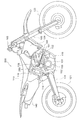
本発明の第1の実施の形態に係る鞍乗り型車両を二輪自動車に適用した場合を例に挙げ、図1ないし図5を参照して説明する。本発明の実施の形態に係る二輪自動車1は、フレーム10、エンジン20、排気管30、前側触媒40、後側触媒50および二次空気導入管80を含んで構成される。
A case where the saddle-ride type vehicle according to the first embodiment of the present invention is applied to a two-wheeled vehicle will be described as an example with reference to FIGS. 1 to 5. The two-
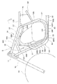
フレーム10は、ヘッドパイプ11と、略平行四辺形状の枠体からなる左側フレーム12と、同じく略平行四辺形状の枠体からなる右側フレーム13とを備えている(図2及び図3参照)。
The
そして、左側フレーム12は、図2に示すように、前端側がヘッドパイプ11の上端側に接続され、そこから後方へと斜め下向きに延びる第1フレーム部12Aと、該第1フレーム部12Aの後端側からく字状(dog leg)に屈曲して後方へと斜め下向きに延び、下端側が前方へと斜め下向きに湾曲して延びる第2フレーム部12Bと、該第2フレーム部12Bの下端側から湾曲して前方へと略水平方向に延びた第3フレーム部12Cと、該第3フレーム部12Cの前端側から湾曲して前方へと斜め上向きに延び、上端側がヘッドパイプ11の下端側に接続された第4フレーム部12Dとを含んで構成されている。
As shown in FIG. 2, the
また、左側フレーム12は、前端側が第1フレーム部12Aと第2フレーム部12Bとの境界部に接続され、そこから後方へと略水平方向に延びるシートレール12Eと、前端側が第2フレーム部12Bの長さ方向中間部に接続され、そこから後方へと斜め上向きに延びたバックステー12Fとを備え、シートレール12Eはその後端側がバックステー12Fの途中部位(図示せず)に接続されている。
The
また、右側フレーム13についても、図3および図5に示すように、左側フレーム12と同様に、第1フレーム部13A、第2フレーム部13B、第3フレーム部13C、第4フレーム部13D、シートレール13Eおよびバックステー13Fを備えている。
As for the
また、ヘッドパイプ11には、図1に示すようにハンドル14に設けられた回転軸(図示せず)が回転可能に挿嵌されている。また、このハンドル14の回転軸は左右方向に延びるアッパーブラケット15の長手方向中間部およびアンダーブラケット16の長手方向中間部に固定されると共に、これらブラケット15,16の左右両端側には左右のフロントフォーク17(一方のみ図示)の上端側が挿入して固定されている。そして、このフロントフォーク17の下端側には前輪60が回転可能に連結されている。
Further, as shown in FIG. 1, a rotary shaft (not shown) provided on the handle 14 is rotatably inserted into the
また、左側フレーム12の第2フレーム部12Bおよび右側フレーム13の第2フレーム部13Bにはスイングアーム18の前端側が揺動可能に連結支持され、このスイングアーム18の後端側には後輪70が回転可能に連結されている。
Further, the front end side of the
さらに、フレーム10のシートレール12Eとバックステー12Fとの間には、エンジン20の後方に位置してエアクリーナ19が配設されている。このエアクリーナ19はエンジン20および二次空気導入管80に供給される空気の中に含まれる塵埃等の異物を除去するものである。
Furthermore, an
エンジン20は、略四角形状の枠体からなる左側フレーム12および右側フレーム13のそれぞれの内側に配設され(図2参照)、これらフレーム12,13に懸架して取り付けられている。そして、エンジン20は、図1および図2に示すように、クランクケース21と、クランクケース21の上側に設けられた気筒22とを含んで構成されている。
The
排気管30は、図2、図3、図5に示すように、エンジン20の気筒22から前方へと円弧状に湾曲して延びた第1パイプ31と、該第1パイプ31から後方へと斜め下向きに延びる第2パイプ32と、該第2パイプ32から後方に向けて略水平方向に延び、前側触媒40と接続される第3パイプ33と、前側触媒40から後方へと略水平方向に延びる第4パイプ34と、第4パイプ34から後方へと斜め上向きに屈曲して延びる第5パイプ35と、該第5パイプ35に接続されるマフラー36とを備えている。
As shown in FIGS. 2, 3, and 5, the
そして、排気管30は、エンジン20からの排気ガスを前側触媒40、後側触媒50およびマフラー36を経由して外部に放出させるものである。
The
前側触媒40はクランクケース21の下側の位置で排気管30の第3パイプ33と第4パイプ34との間に配設されている。そして、前側触媒40は、その左右方向の幅寸法が上下方向の高さ寸法よりも大きな扁平形状に形成されている。このため、前側触媒40は、クランクケース21の下側を水平方向に延びる排気管30の第3パイプ33および第4パイプ34から下側に突出することがなくなり、車体の地面からの最低高さが確保される。
The
また、排気管30のうち前側触媒40よりも下流側に位置するマフラー36には後側触媒50が配設されている。そして、これら前側触媒40および後側触媒50は、エンジン20から排出される排気ガス中に含まれる有害成分(HC、NOx等)を燃焼させ、排気ガスを浄化するものである。
A
二次空気導入管80は、エアクリーナ19を介した外部の空気を排気管30の第4パイプ34を通じて後側触媒50に導き、後側触媒50における排気ガスの燃焼効率を高めるようになっている。この二次空気導入管80は、金属パイプおよびゴムホース等を用いて図2ないし図5に示すように形成されている。
The secondary
そして、図2に示すように、二次空気導入管80は、上流端側がエアクリーナ19の前端側に接続され、そこから前方へと斜め右向きに延びる第1管部80Aと、該第1管部80Aから気筒22の右側方でかつ上方を緩やかに円弧状に湾曲しながら延びる第2管部80Bと、車両の中心線L(図4参照)を跨いで左右方向の一方側(右側)となる該第2管部80Bから気筒22の前方を左右方向の他方側(左側)へと延びる第3管部80Cと、該第3管部80Cから垂下して延びる第4管部80Dとを備えている。
As shown in FIG. 2, the secondary
また、二次空気導入管80は、第4管部80Dからく字状に屈曲して後方へと斜め下向きに延びる第5管部80Eと、該第5管部80EからL字状に屈曲して後方へと略水平方向に延び、側面視で左側フレーム12の第3フレーム部12Cと部分的に重なり合った第6管部80Fと、該第6管部80Fから右向きに円弧状に湾曲しながら水平方向に延び、接続部である下流端80G1側が前側触媒40と後側触媒50との間に位置する排気管30の第4パイプ34に接続された第7管部80G(図3参照)とを備えている。なお、第7管部80Gの接続部80G1はクランクケース21の下側に配置されている。
Further, the secondary
そして、これら二次空気導入管80のうち、第3〜第5管部80C〜80Eは、図2に示すように前輪60とエンジン20との間となる車体の前方に形成される空間部S内に向けて露出して配置されている。そして、これら第3〜第5管部80C〜80Eは車体のカバー等で覆われることなく、車体の外方となる前方および側方から視認できるようになっている。
Of these secondary
また、二次空気導入管80のうち、第1管部80A、第2管部80B、第3管部80C、第4管部80D、第5管部80Eの下側部位80E1、第6管部80Fの後側部位80F、第7管部80Gは、金属パイプによって形成され、これらの管部内を流れる二次空気の冷却を効率よく行なえるようになっている。なお、第5管部80Eの上側部位80E2および第6管部80Fの前側部位80F2はゴムホースを用いて形成されている。
Of the secondary
このため、二次空気導入管80内を流れる二次空気は、第3〜第5管部80C〜80E内を通過するときに、空間部Sの冷たい空気によって外部から冷却される。従って、これら第3〜第5管部80C〜80Eは、二次空気を冷却するための二次空気冷却管部としての機能を有する。
For this reason, the secondary air flowing through the secondary
このように構成される本実施の形態によれば、二次空気導入管80のうち、二次空気冷却管部である第3〜第5管部80C〜80Eを前輪60よりも後方でかつエンジン20よりも前方の空間部Sに露出させる構成としたので、二次空気導入管80の第3〜第5管部80C〜80Eにより二次空気を冷却して二次空気中の酸素濃度を高めることができる。
According to the present embodiment configured as described above, in the secondary
従って、二次空気導入管80から排気管30内へと導かれる二次空気が後側触媒50を通過するときの二次空気による排気ガスの燃焼効率を十分に高めることができ、後側触媒50による排気ガスの浄化を効率的に行なうことができる。
Therefore, the combustion efficiency of the exhaust gas by the secondary air when the secondary air guided from the secondary
次に、図6ないし図8は第1の参考例を示している。 Next, FIGS. 6 to 8 show a first reference example .
図6において、二輪自動車100のフレーム110はメインフレーム111を有している。メインフレーム111は車体の前半部にて、車体の前方から斜め下向きに延設されており、その前端部にはヘッドパイプ127が設けられている。ヘッドパイプ127は、フロントフォーク105を回動可能に軸支している。フロントフォーク105の上端部にはハンドル109が設けられている。フロントフォーク105の下端部には前輪123が軸支されている。
In FIG. 6, the
また、フレーム110はシートレール112を有しており、シートレール112は、メインフレーム111の途中部位に接続され、そこから後方へと斜め上向きに延設されている。シートレール112の上方にはシート113が配置されている。さらに、フレーム110はバックステー114を有しており、該バックステー114はメインフレーム111の後端部に接続され、そこから後方へと斜め上向きに延設されている。バックステー114の後端部はシートレール112に接続されている。
Further, the
メインフレーム111の後端部にはリヤアームブラケット117が取り付けられている。メインフレーム111の後部下方にはエンジン130が配置されており、エンジン130は二輪自動車100における前後方向の中央付近に位置している。エンジン130は、メインフレーム111の途中部位111B,111Cにて懸架されると共に、リヤアームブラケット117に支持されて、フレーム110に対して固定されている。
A
リヤアームブラケット117にはリヤアーム119の一端部がピポット軸104を介して取り付けられている。リヤアーム119の他端部は後輪121を軸支しており、リヤアーム119はリヤアームブラケット117に設けられたピポット軸104を支点として、後輪121と共にフレーム110に対して揺動可能となっている。リヤアーム119とシートレール112との間にはリヤサスペンション118が設けられている。
One end of a
フレーム110は、車体カバー106およびレッグシールド108により覆われている。レッグシールド108は車体カバー106の前方に取り付けられており、前方が開口した正面視略矩形状をなしている(図7参照)。また、レッグシールド108は、前方に向かうに従って徐々に内側に絞り込まれる形状になっている。なお、図7には、レッグシールド108の稜線108B,108Cが示されている。
The
エンジン130は単気筒4サイクルエンジンであり、内部にクランクシャフトおよび変速機構を収納するクランクケース131と、該クランクケース131の上部に設けられ、内部にシリンダを有する気筒132とを備えている。
The
気筒132には、エンジン130内に空気及び燃料を導入する吸気ポートが形成されている。吸気ポートにはマニホールドが接続されており、マニホールドの上流側にはインジェクタが取り付けられたスロットルボディ135が接続されている。気筒132の内部には吸気ポートから供給された燃料を、空気とともに燃焼する燃焼室が形成されている。燃料の燃焼により発生する排気ガスは、気筒132の前部に形成された排気ポートからエンジン130の外に排出される。
The
気筒132に形成される排気ポートには、排気管150が接続されている。排気管150は、排気ポートから前方へと斜め下向きに延設された後、屈曲し、後方へと斜め下向きに延設されている。その後、さらに曲がりクランクケース131の下方において後方に向けて延設されている。また、排気管150のクランクケース131よりも後側の部分は、後輪121の側方に配置される消音器140に収容されている。
An
図8に示すように、排気管150には、前側触媒収容部151と、当該前側触媒収容部151よりも下流側に配置される後側触媒収容部152とが設けられている。前側触媒収容部151は、その内部に主として還元作用をなす前側触媒151Aを有している。後側触媒収容部152は、その内部に主として酸化作用をなす後側触媒152Aを有している。
As shown in FIG. 8, the
排気管150には排気ガスに二次空気を供給する二次空気導入管160が接続されている。二次空気導入管160の下流側(排気管150側)は、クランクケース131より前方、かつ、当該クランクケース131の下面より上方にて配設されて、その下流側端部160Aは、排気管150の、クランクケース131より前方に配設されている部分に接続されている。
A secondary
そして、二次空気導入管160は、図6および図7に示すように、前側触媒収容部151との接続部分から車幅方向内側に向けて延設された後、屈曲して車両の上方に向けて延設された第1管部160Aと、第1管部160Aから上向きにクランク状に屈曲し、上流側端部がエンジン130の側方に配置されるリードバルブアッシュ161に接続された第2管部160Bと、リードバルブアッシュ161から後方へと延設されてエアクリーナ(図示せず)に接続された第3管部160Cとを備えている。
As shown in FIGS. 6 and 7, the secondary
ここで、二次空気導入管160のうち、第1管部160Aおよび第2管部160Bは前輪23よりも後方で、かつ車体の前方となる空間部S1内に露出しており、二次空気冷却管部となっている。そして、第1管部160Aおよび第2管部160Bは、図7に示すように、レッグシールド108の前側の開口端108Dを通じて車体の前方から視認できる位置に配置されている。
Here, in the secondary
なお、リードバルブアッシュ161とエアクリーナとを連結する第3管部160Cの側壁には開口が形成されており、その開口にはスロットルボディ135の下部に取り付けられた箱状のレゾネータ165が接続されている。レゾネータ165には排気管150へ流入する二次空気の一部が第3管部160Cから流入しており、二次空気の脈動により生じる空気の干渉が抑制されて、空気騒音が低減されている。
Note that an opening is formed in the side wall of the third pipe portion 160C that connects the
このように構成される本参考例でも、二次空気導入管160の第1管部160Aおよび第2管部160Bを前輪23よりも後方で、かつ車体の前方となる空間部S1内に露出させる構成としてので、二次空気導入管160を効率よく冷却することができ、第1の実施の形態とほぼ同様の作用効果を得ることができる。
Also in this reference example configured as described above, the
次に、図9は第2の参考例を示している。同図において、図6ないし図8と同一箇所については同一符号を付し、以下において詳細な説明を省略する。 Next, FIG. 9 shows a second reference example . In this figure, the same parts as those shown in FIGS.
図9において、排気管50には前側触媒収容部51と後側触媒収容部52との間の位置に二次空気導入管263の上流端側が接続されている。また、二次空気導入管263の下流端側はエアクリーナ(図示せず)に接続されている。
In FIG. 9, the upstream end side of the secondary
ここで、二次空気導入管263は、前輪123よりも後方で、かつ車体の側方の空間部に露出するように配置されている。また、二次空気導入管263は車体の側方から視認できる位置に配置されている。
Here, the secondary
このように構成される本参考例でも、二次空気導入管263を、前輪123よりも後方で、かつ車体の側方の空間部に露出するように配置したので、二次空気導入管263を効率よく冷却でき、第1の実施の形態とほぼ同様の作用効果を得ることができる。
Also in this reference example configured as described above, the secondary
なお、第1の実施の形態では、エンジンをフレームに固定する構成とした場合を例に挙げて説明したが、本発明はこれに限らず、鞍乗り型車両を、例えば多くのスクータ等に採用されているようなエンジンユニット全体が後輪と共にスイングするユニットスイング式の車両に適用してもよい。 In the first embodiment, the case where the engine is fixed to the frame has been described as an example. However, the present invention is not limited to this, and a saddle-ride type vehicle is employed in many scooters, for example. The present invention may be applied to a unit swing type vehicle in which the whole engine unit swings with the rear wheel.
また、第1の実施の形態では、鞍乗り型車両として二輪自動車を例に挙げて説明したが、本発明はこれに限らず、例えば三輪自動車、バギー等の他の鞍乗り型車両に適用してもよい。 In the first embodiment, a two-wheeled vehicle has been described as an example of a saddle-ride type vehicle. However, the present invention is not limited to this, and may be applied to other saddle-ride type vehicles such as a three-wheeled vehicle and a buggy. May be.
1,100,200 自動二輪車(鞍乗り型車両)、10,110 フレーム、12 左側フレーム、13 右側フレーム、19 エアクリーナ、20,130 エンジン、21,131 クランクケース、22,132 気筒、30,150 排気管、80,160,263 二次空気導入管、80A 第1管部、80B 第2管部、80C 第3管部(二次空気冷却管部)、80D 第4管部(二次空気冷却管部)、80E 第5管部(二次空気冷却管部)、80F 第6管部、80G 第7管部、80G1 接続部、 160A 第1管部(二次空気冷却管部)、 160B 第2管部(二次空気冷却管部)、 160C 第3管部。 1,100,200 Motorcycle (saddle-ride type vehicle) 10,110 frame, 12 left frame, 13 right frame, 19 air cleaner, 20,130 engine, 21,131 crankcase, 22,132 cylinder, 30,150 exhaust Pipe, 80, 160, 263 secondary air introduction pipe, 80A first pipe part, 80B second pipe part, 80C third pipe part (secondary air cooling pipe part), 80D fourth pipe part (secondary air cooling pipe) Part), 80E fifth pipe part (secondary air cooling pipe part), 80F sixth pipe part, 80G seventh pipe part, 80G1 connection part, 160A first pipe part (secondary air cooling pipe part), 160B second A pipe part (secondary air cooling pipe part), 160C 3rd pipe part.
Claims (6)
該エンジンの排気管の途中に配置される前側触媒と、
前記排気管の途中において、前記前側触媒より下流側に配置される後側触媒と、
下流端側が前記前側触媒と前記後側触媒との間の位置で前記排気管に接続される二次空気導入管と、
を備えた鞍乗り型車両において、
前記二次空気導入管の一部を、前記前輪よりも後方で、車体の前方および側方のうち少なくとも一方に向けて露出した二次空気冷却管部とし、
前記二次空気冷却管部を金属製パイプを用いて形成し、
前記二次空気導入管の、前記二次空気冷却管部より下流の一部をゴムホースを用いて形成したことを特徴とする鞍乗り型車両。 An engine disposed between the front and rear wheels;
A front catalyst disposed in the middle of the exhaust pipe of the engine;
In the middle of the exhaust pipe, a rear catalyst disposed downstream from the front catalyst;
A secondary air introduction pipe whose downstream end is connected to the exhaust pipe at a position between the front catalyst and the rear catalyst;
In a saddle-ride type vehicle equipped with
A portion of the secondary air introduction pipe is a secondary air cooling pipe portion exposed rearward of the front wheel and toward at least one of the front and side of the vehicle body ;
Forming the secondary air cooling pipe using a metal pipe;
A saddle-ride type vehicle , wherein a part of the secondary air introduction pipe downstream from the secondary air cooling pipe is formed using a rubber hose .
Priority Applications (11)
| Application Number | Priority Date | Filing Date | Title |
|---|---|---|---|
| JP2006330004A JP4871107B2 (en) | 2006-12-06 | 2006-12-06 | Saddle riding |
| EP07023188A EP1933010B1 (en) | 2006-12-06 | 2007-11-29 | Motorcycle |
| DE602007007283T DE602007007283D1 (en) | 2006-12-06 | 2007-11-29 | motorcycle |
| AT07023188T ATE472048T1 (en) | 2006-12-06 | 2007-11-29 | MOTORCYCLE |
| ES07023188T ES2346357T3 (en) | 2006-12-06 | 2007-11-29 | MOTORCYCLE. |
| BRPI0704401-1A BRPI0704401B1 (en) | 2006-12-06 | 2007-12-03 | Ride Type Vehicle |
| CN2007101865085A CN101239642B (en) | 2006-12-06 | 2007-12-04 | Straddle-type vehicle |
| US11/951,220 US8439142B2 (en) | 2006-12-06 | 2007-12-05 | Straddle type vehicle |
| DE602007010075T DE602007010075D1 (en) | 2006-12-06 | 2007-12-06 | motorcycle |
| AT07023695T ATE486201T1 (en) | 2006-12-06 | 2007-12-06 | MOTORCYCLE |
| EP07023695A EP1933011B1 (en) | 2006-12-06 | 2007-12-06 | Motorcycle |
Applications Claiming Priority (1)
| Application Number | Priority Date | Filing Date | Title |
|---|---|---|---|
| JP2006330004A JP4871107B2 (en) | 2006-12-06 | 2006-12-06 | Saddle riding |
Publications (2)
| Publication Number | Publication Date |
|---|---|
| JP2008144613A JP2008144613A (en) | 2008-06-26 |
| JP4871107B2 true JP4871107B2 (en) | 2012-02-08 |
Family
ID=39027553
Family Applications (1)
| Application Number | Title | Priority Date | Filing Date |
|---|---|---|---|
| JP2006330004A Active JP4871107B2 (en) | 2006-12-06 | 2006-12-06 | Saddle riding |
Country Status (8)
| Country | Link |
|---|---|
| US (1) | US8439142B2 (en) |
| EP (1) | EP1933010B1 (en) |
| JP (1) | JP4871107B2 (en) |
| CN (1) | CN101239642B (en) |
| AT (1) | ATE472048T1 (en) |
| BR (1) | BRPI0704401B1 (en) |
| DE (1) | DE602007007283D1 (en) |
| ES (1) | ES2346357T3 (en) |
Families Citing this family (9)
| Publication number | Priority date | Publication date | Assignee | Title |
|---|---|---|---|---|
| DE602008005145D1 (en) * | 2008-08-29 | 2011-04-07 | Yamaha Motor Res & Dev Europ S R L | An exhaust gas purification device for a motorcycle and a motorcycle equipped with such an exhaust gas purification device |
| JP5362694B2 (en) | 2010-12-07 | 2013-12-11 | 本田技研工業株式会社 | Saddle riding vehicle |
| CN102996296B (en) * | 2011-09-16 | 2015-07-01 | 雅马哈发动机株式会社 | Motorcycle |
| JP6231751B2 (en) * | 2013-01-30 | 2017-11-15 | 本田技研工業株式会社 | Exhaust gas sensor arrangement structure for motorcycles |
| JP2017150309A (en) * | 2014-07-04 | 2017-08-31 | ヤマハ発動機株式会社 | Engine unit and ride type vehicle |
| JP2017150311A (en) * | 2014-07-04 | 2017-08-31 | ヤマハ発動機株式会社 | Engine unit and ride type vehicle |
| EP3236037A4 (en) * | 2014-12-19 | 2018-03-28 | Yamaha Hatsudoki Kabushiki Kaisha | Saddle-type vehicle |
| JP2020131839A (en) * | 2019-02-15 | 2020-08-31 | 本田技研工業株式会社 | Intake duct structure of vehicle |
| CN114605040A (en) * | 2022-03-31 | 2022-06-10 | 青岛宝菲尔物流装备有限公司 | Water treatment container |
Family Cites Families (28)
| Publication number | Priority date | Publication date | Assignee | Title |
|---|---|---|---|---|
| US3061416A (en) * | 1957-11-22 | 1962-10-30 | George P Kazokas | Catalytic muffler |
| US3672172A (en) * | 1971-03-15 | 1972-06-27 | Gary L Hammond | Simplified supercharged internal combustion engine with emissions control |
| GB1469527A (en) * | 1973-03-30 | 1977-04-06 | Atomic Energy Authority Uk | Manufacture of catalysts |
| JPS52102920A (en) * | 1976-02-26 | 1977-08-29 | Toyota Motor Corp | Secondary-air supply system for exhaust gas cleaner |
| JPS5741416A (en) * | 1980-08-22 | 1982-03-08 | Honda Motor Co Ltd | Discharge gas cleaner of internal combustion engine with multi-cylinder for motorcycle |
| JPS5832913A (en) * | 1981-08-24 | 1983-02-26 | Honda Motor Co Ltd | Exhaust gas purifier of internal-combustion engine |
| JPS595709U (en) * | 1982-07-05 | 1984-01-14 | 本田技研工業株式会社 | Secondary air supply device for exhaust purification equipment for motorcycles |
| JPS62284917A (en) * | 1986-06-02 | 1987-12-10 | Yamaha Motor Co Ltd | Secondary air feed device for purifying exhaust gas of motorcycle |
| JPH04140413A (en) * | 1990-10-01 | 1992-05-14 | Yamaha Motor Co Ltd | Exhaust emission control device for internal combustion engine |
| JP3008488B2 (en) * | 1990-11-22 | 2000-02-14 | スズキ株式会社 | Secondary air supply for two-stroke engine |
| JP3314241B2 (en) | 1992-04-06 | 2002-08-12 | ヤマハ発動機株式会社 | Exhaust gas purification device for motorcycle engine |
| JP3302047B2 (en) * | 1992-06-19 | 2002-07-15 | ヤマハ発動機株式会社 | Exhaust gas purification device for motorcycle |
| JP3281190B2 (en) * | 1994-07-27 | 2002-05-13 | ヤマハ発動機株式会社 | Exhaust gas purification device for internal combustion engine for motorcycle |
| JP3616683B2 (en) * | 1995-11-16 | 2005-02-02 | 本田技研工業株式会社 | Abnormality detection device for air pump of internal combustion engine |
| JP4540762B2 (en) * | 1999-01-18 | 2010-09-08 | 本田技研工業株式会社 | Saddle-type vehicle with exhaust secondary air valve |
| JP3631035B2 (en) * | 1999-02-22 | 2005-03-23 | 本田技研工業株式会社 | Exhaust secondary air supply control device for internal combustion engine |
| JP2000282855A (en) * | 1999-03-29 | 2000-10-10 | Yamaha Motor Co Ltd | Exhaust emission control device for saddle type vehicle |
| JP3427824B2 (en) | 2000-09-18 | 2003-07-22 | スズキ株式会社 | Scooter exhaust gas purification equipment |
| DE10048580A1 (en) * | 2000-09-30 | 2002-04-11 | Volkswagen Ag | Exhaust system of an internal combustion engine with a catalyst |
| JP2002161737A (en) * | 2000-11-29 | 2002-06-07 | Sanshin Ind Co Ltd | Exhaust gas cleaning device in engine and small size ship carrying this device |
| FR2827908B1 (en) * | 2001-07-26 | 2004-02-13 | Peugeot Motocycles Sa | SYSTEM FOR PURIFYING EXHAUST GASES FROM A TWO-STROKE HEAT ENGINE, PARTICULARLY FOR A TWO-WHEELED VEHICLE |
| JP4177157B2 (en) * | 2003-04-24 | 2008-11-05 | トヨタ自動車株式会社 | Abnormality judgment device for secondary air supply device |
| MY141622A (en) * | 2003-06-19 | 2010-05-31 | Yamaha Motor Co Ltd | Exhaust system for an engine |
| JP2005138820A (en) * | 2003-10-16 | 2005-06-02 | Yamaha Motor Co Ltd | Saddle ride type vehicle |
| TW200530493A (en) * | 2004-02-24 | 2005-09-16 | Yamaha Motor Co Ltd | Exhaust gas purifying device for engine |
| US7263826B2 (en) * | 2004-07-13 | 2007-09-04 | Sentec E&E Co., Ltd. | Muffler device with catalysts for improving purifying exhaust gas of nitrogen oxides within a motorcycle exhaust pipe |
| JP4545013B2 (en) * | 2005-02-21 | 2010-09-15 | 本田技研工業株式会社 | Exhaust secondary air introduction structure for motorcycles |
| JP2007040249A (en) | 2005-08-04 | 2007-02-15 | Yamaha Motor Co Ltd | Engine having exhaust emission control function and vehicle |
-
2006
- 2006-12-06 JP JP2006330004A patent/JP4871107B2/en active Active
-
2007
- 2007-11-29 AT AT07023188T patent/ATE472048T1/en not_active IP Right Cessation
- 2007-11-29 ES ES07023188T patent/ES2346357T3/en active Active
- 2007-11-29 DE DE602007007283T patent/DE602007007283D1/en active Active
- 2007-11-29 EP EP07023188A patent/EP1933010B1/en active Active
- 2007-12-03 BR BRPI0704401-1A patent/BRPI0704401B1/en active IP Right Grant
- 2007-12-04 CN CN2007101865085A patent/CN101239642B/en active Active
- 2007-12-05 US US11/951,220 patent/US8439142B2/en active Active
Also Published As
| Publication number | Publication date |
|---|---|
| ES2346357T3 (en) | 2010-10-14 |
| CN101239642A (en) | 2008-08-13 |
| US20080135317A1 (en) | 2008-06-12 |
| CN101239642B (en) | 2011-06-08 |
| ATE472048T1 (en) | 2010-07-15 |
| BRPI0704401B1 (en) | 2019-07-16 |
| EP1933010B1 (en) | 2010-06-23 |
| BRPI0704401A (en) | 2008-07-22 |
| JP2008144613A (en) | 2008-06-26 |
| US8439142B2 (en) | 2013-05-14 |
| DE602007007283D1 (en) | 2010-08-05 |
| EP1933010A1 (en) | 2008-06-18 |
Similar Documents
| Publication | Publication Date | Title |
|---|---|---|
| JP4871107B2 (en) | Saddle riding | |
| US7882700B2 (en) | Exhaust pipe structure | |
| JP4546310B2 (en) | Exhaust system for motorcycle engine | |
| US8584788B2 (en) | Exhaust system for motorcycle | |
| JP2008222078A (en) | Motorcycle | |
| JP2011073590A (en) | Vehicle body frame structure of saddle-ride type vehicle | |
| JP5103344B2 (en) | Motorcycle | |
| JP2013231384A (en) | Muffler and saddle-riding type vehicle | |
| JP2007040250A (en) | Saddle riding type vehicle having exhaust emission control function | |
| JP2019183673A (en) | Arrangement structure of exhaust gas sensor | |
| JP2007112153A (en) | Saddle type vehicle | |
| JP2004249774A (en) | Motorcycle | |
| JP4911612B2 (en) | Motorcycle exhaust system | |
| TW201026945A (en) | An exhaust gas purifying apparatus for a motorcycle and a motorcycle equipped with such an exhaust gas purifying apparatus | |
| JP3143323U (en) | Saddle-type vehicle with exhaust gas purification function | |
| JP2020026755A (en) | Catalyst arrangement structure of saddle riding-type vehicle | |
| JP2017149166A (en) | Saddle-riding type vehicle | |
| JP5168462B2 (en) | Exhaust gas treatment mechanism, engine unit equipped with the same, and vehicle equipped with the engine unit | |
| JP2008062813A (en) | Riding type vehicle | |
| JP2017149167A (en) | Saddle-riding type vehicle | |
| WO2023189962A1 (en) | Saddle riding-type vehicle | |
| JP7275775B2 (en) | motorcycle | |
| JP6638776B1 (en) | Motorcycle | |
| JP2023165213A (en) | Straddle-riding type vehicle | |
| JP2004345642A (en) | Exhaust device for motorcycle |
Legal Events
| Date | Code | Title | Description |
|---|---|---|---|
| A621 | Written request for application examination |
Free format text: JAPANESE INTERMEDIATE CODE: A621 Effective date: 20091111 |
|
| A131 | Notification of reasons for refusal |
Free format text: JAPANESE INTERMEDIATE CODE: A131 Effective date: 20110215 |
|
| A977 | Report on retrieval |
Free format text: JAPANESE INTERMEDIATE CODE: A971007 Effective date: 20110217 |
|
| A521 | Request for written amendment filed |
Free format text: JAPANESE INTERMEDIATE CODE: A523 Effective date: 20110408 |
|
| TRDD | Decision of grant or rejection written | ||
| A01 | Written decision to grant a patent or to grant a registration (utility model) |
Free format text: JAPANESE INTERMEDIATE CODE: A01 Effective date: 20111115 |
|
| A01 | Written decision to grant a patent or to grant a registration (utility model) |
Free format text: JAPANESE INTERMEDIATE CODE: A01 |
|
| A61 | First payment of annual fees (during grant procedure) |
Free format text: JAPANESE INTERMEDIATE CODE: A61 Effective date: 20111118 |
|
| R150 | Certificate of patent or registration of utility model |
Free format text: JAPANESE INTERMEDIATE CODE: R150 Ref document number: 4871107 Country of ref document: JP Free format text: JAPANESE INTERMEDIATE CODE: R150 |
|
| FPAY | Renewal fee payment (event date is renewal date of database) |
Free format text: PAYMENT UNTIL: 20141125 Year of fee payment: 3 |
|
| R250 | Receipt of annual fees |
Free format text: JAPANESE INTERMEDIATE CODE: R250 |
|
| R250 | Receipt of annual fees |
Free format text: JAPANESE INTERMEDIATE CODE: R250 |
|
| R250 | Receipt of annual fees |
Free format text: JAPANESE INTERMEDIATE CODE: R250 |
|
| R250 | Receipt of annual fees |
Free format text: JAPANESE INTERMEDIATE CODE: R250 |
|
| R250 | Receipt of annual fees |
Free format text: JAPANESE INTERMEDIATE CODE: R250 |
|
| R250 | Receipt of annual fees |
Free format text: JAPANESE INTERMEDIATE CODE: R250 |
|
| R250 | Receipt of annual fees |
Free format text: JAPANESE INTERMEDIATE CODE: R250 |
|
| R250 | Receipt of annual fees |
Free format text: JAPANESE INTERMEDIATE CODE: R250 |
|
| R250 | Receipt of annual fees |
Free format text: JAPANESE INTERMEDIATE CODE: R250 |