WO2016098487A1 - 電流推定装置 - Google Patents
電流推定装置 Download PDFInfo
- Publication number
- WO2016098487A1 WO2016098487A1 PCT/JP2015/081554 JP2015081554W WO2016098487A1 WO 2016098487 A1 WO2016098487 A1 WO 2016098487A1 JP 2015081554 W JP2015081554 W JP 2015081554W WO 2016098487 A1 WO2016098487 A1 WO 2016098487A1
- Authority
- WO
- WIPO (PCT)
- Prior art keywords
- voltage
- phase
- axis
- current
- amplitude
- Prior art date
- Legal status (The legal status is an assumption and is not a legal conclusion. Google has not performed a legal analysis and makes no representation as to the accuracy of the status listed.)
- Ceased
Links
Images












Classifications
-
- H—ELECTRICITY
- H02—GENERATION; CONVERSION OR DISTRIBUTION OF ELECTRIC POWER
- H02P—CONTROL OR REGULATION OF ELECTRIC MOTORS, ELECTRIC GENERATORS OR DYNAMO-ELECTRIC CONVERTERS; CONTROLLING TRANSFORMERS, REACTORS OR CHOKE COILS
- H02P6/00—Arrangements for controlling synchronous motors or other dynamo-electric motors using electronic commutation dependent on the rotor position; Electronic commutators therefor
- H02P6/14—Electronic commutators
- H02P6/16—Circuit arrangements for detecting position
-
- H—ELECTRICITY
- H02—GENERATION; CONVERSION OR DISTRIBUTION OF ELECTRIC POWER
- H02P—CONTROL OR REGULATION OF ELECTRIC MOTORS, ELECTRIC GENERATORS OR DYNAMO-ELECTRIC CONVERTERS; CONTROLLING TRANSFORMERS, REACTORS OR CHOKE COILS
- H02P21/00—Arrangements or methods for the control of electric machines by vector control, e.g. by control of field orientation
-
- H—ELECTRICITY
- H02—GENERATION; CONVERSION OR DISTRIBUTION OF ELECTRIC POWER
- H02P—CONTROL OR REGULATION OF ELECTRIC MOTORS, ELECTRIC GENERATORS OR DYNAMO-ELECTRIC CONVERTERS; CONTROLLING TRANSFORMERS, REACTORS OR CHOKE COILS
- H02P27/00—Arrangements or methods for the control of AC motors characterised by the kind of supply voltage
- H02P27/04—Arrangements or methods for the control of AC motors characterised by the kind of supply voltage using variable-frequency supply voltage, e.g. inverter or converter supply voltage
-
- H—ELECTRICITY
- H02—GENERATION; CONVERSION OR DISTRIBUTION OF ELECTRIC POWER
- H02P—CONTROL OR REGULATION OF ELECTRIC MOTORS, ELECTRIC GENERATORS OR DYNAMO-ELECTRIC CONVERTERS; CONTROLLING TRANSFORMERS, REACTORS OR CHOKE COILS
- H02P9/00—Arrangements for controlling electric generators for the purpose of obtaining a desired output
- H02P9/04—Control effected upon non-electric prime mover and dependent upon electric output value of the generator
Definitions
- the present invention relates to a power conversion circuit and a current estimation device applied to a system including a rotating electrical machine that performs power transmission with a DC power supply by energization operation to the power conversion circuit.
- Patent Document 1 a control device that calculates d and q axis currents in a dq coordinate system based on a voltage equation of a rotating electrical machine is known. Specifically, in this control device, the d and q axis currents are calculated based on the d axis inductance.
- a technique for estimating a current flowing between a DC power supply and a power conversion circuit in a system including a power conversion circuit and a rotating electrical machine that transmits electric power to the DC power supply by energizing the power conversion circuit In this technique, the d and q axis currents are calculated based on a predetermined d axis inductance, and the current flowing between the DC power supply and the power conversion circuit is estimated based on the calculated d and q axis currents.
- the d-axis inductance changes due to the effect of abrupt magnetic saturation that occurs when the d-axis current is greater than zero.
- an actual d-axis inductance greatly deviates from a predetermined d-axis inductance, and an estimation error of a current flowing between the DC power supply and the power conversion circuit becomes large. It is also conceivable to accurately grasp the characteristics of the d-axis inductance when the above-described sudden magnetic saturation occurs. However, it is difficult to accurately grasp this characteristic.
- the main object of the present invention is to provide a current estimation device that can suitably suppress an estimation error of a current flowing between a DC power supply and a power conversion circuit.
- the current estimation device is applied to a system including a power conversion circuit and a rotating electrical machine that transmits power by a power supply operation to the power conversion circuit.
- the current estimation device includes: a current estimation unit configured to estimate a current flowing between the DC power supply and the power conversion circuit based on a predetermined d-axis inductance of the rotating electrical machine; and a dq coordinate system of the rotating electrical machine.
- the d-axis current becomes a predetermined value larger than 0, the voltage phase that is the phase of the voltage vector to cause the q-axis component of the voltage vector of the power conversion circuit to follow the induced voltage component of the rotating electrical machine.
- a phase operation means for operating.
- the d-axis current is zero.
- the q-axis component of the voltage vector is converted into the induced voltage of the rotating electrical machine by the operation of the voltage phase.
- the ingredients For this reason, it can be avoided that the actual d-axis inductance greatly deviates from a predetermined d-axis inductance used for current estimation. Thereby, the estimation error of the current by the current estimation means can be suitably suppressed.
- the other current estimation apparatus is applied to a system including a power conversion circuit and a rotating electrical machine that performs power transmission with a DC power supply by energization operation to the power conversion circuit.
- the current estimation device includes: a current estimation unit that estimates a current flowing between the DC power supply and the power conversion circuit based on a predetermined d-axis inductance of the rotating electrical machine; and a dq coordinate system of the rotating electrical machine.
- the voltage that is the amplitude of the voltage vector to cause the q-axis component of the voltage vector of the power conversion circuit to follow the induced voltage component of the rotating electrical machine An amplitude operation means for operating the amplitude is provided.
- the other current estimation apparatus is applied to a system including a power conversion circuit and a rotating electrical machine that performs power transmission with a DC power supply by energization operation to the power conversion circuit.
- the current estimation device is configured such that an amplitude of a voltage vector of the power conversion circuit is a voltage amplitude, a phase of the voltage vector is a voltage phase, and based on a predetermined d-axis inductance of the rotating electrical machine,
- a current estimating means for estimating a current flowing between the power conversion circuit and a q-axis component of the voltage vector on condition that a d-axis current in the dq coordinate system of the rotating electrical machine is a predetermined value larger than 0;
- the d-axis current is zero.
- the voltage phase is manipulated in the direction in which the voltage vector is rotated clockwise with respect to the q axis. Further, the q-axis component is made to follow the induced voltage component by the operation of the voltage amplitude. For this reason, it can be avoided that the actual d-axis inductance greatly deviates from a predetermined d-axis inductance used for current estimation. Thereby, the estimation error of the current by the current estimation means can be suitably suppressed.
- the current estimation device manipulates the voltage amplitude so that the q-axis component follows the induced voltage component in a region where the deviation between the q-axis component and the induced voltage component is less than a specified value.
- Manipulating the voltage phase in the direction of rotating the voltage vector clockwise increases the power generated by the rotating electrical machine.
- the generated power may be reduced. For this reason, in order to suppress the reduction
- the q-axis component is brought close to the induced voltage component without reducing the generated power. Therefore, the reduction
- the system includes a magnetic pole position detecting unit that detects the magnetic pole position of the rotating electrical machine at a predetermined period, and the voltage phase is set to be equal to or smaller than a predetermined phase that is greater than 0 ° and smaller than 90 °.
- a phase calculation means for calculating the voltage phase for controlling the rotating electrical machine as a condition
- the voltage phase calculated by the phase calculation means and the magnetic pole position detected by the magnetic pole position detection means
- a voltage control means for controlling an applied voltage of the rotating electrical machine, wherein the phase operation means is calculated by the phase calculation means until the deviation becomes a value less than the specified value, with the specified period being a control period.
- the amplitude operation means follows the q-axis component following the induced voltage component with a cycle shorter than the specified cycle as a control cycle.
- the operation of the voltage amplitude for the adjustment may be performed by adjusting the applied voltage.
- the control period of the phase operation means is also set to the specified period.
- the control period of the amplitude operation means that does not require voltage phase information is set to a period shorter than the control period of the phase operation means. For this reason, the follow-up accuracy of the q-axis component to the induced voltage component by the amplitude operation unit is higher than the follow-up accuracy by the phase operation unit. Therefore, by operating a voltage amplitude with high tracking accuracy in a region where the deviation between the q-axis component and the induced voltage component is less than a specified value, the q-axis component can be made to follow the induced voltage component quickly and with high accuracy. . As a result, it is possible to more suitably suppress the current estimation error.
- (A), (b) is a time chart which shows the rotation fluctuation
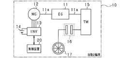
- a motorcycle 10 includes an engine 11, a starting generator 12 as a rotating electric machine, an inverter 13 as a power conversion circuit, a battery 14 as a DC power source, a transmission 15, a clutch 16, and driving wheels. 17 and a control device 20.
- the engine 11 is an in-vehicle main unit of the motorcycle 10, and is a single-cylinder four-stroke engine in the present embodiment.
- the combustion control of the engine 11 may be performed by another control device (not shown) different from the control device 20, or may be performed by the control device 20.
- the input side (specifically, for example, the engine side pulley) of the transmission 15 is connected to the first end of the output shaft of the engine 11 (hereinafter referred to as the crankshaft 11a).
- an automatic transmission specifically, a continuously variable transmission
- Drive wheels 17 are connected to the output side of the transmission 15 (specifically, for example, a drive wheel pulley) via a clutch 16 and a secondary reduction mechanism (not shown).
- the clutch 16 is in a state capable of transmitting power between the output side of the transmission 15 and the drive wheel 17 (hereinafter referred to as a clutch meet state), and the power between the output side of the transmission 15 and the drive wheel 17 is cut off. It is possible to switch to one of the following states (hereinafter referred to as the clutch disengaged state).
- an automatic centrifugal clutch is used as the clutch 16.
- the automatic centrifugal clutch according to the present embodiment includes a clutch shoe connected to the output side of the transmission 15, a clutch spring, and a clutch outer connected to the drive wheel 17 side.
- the clutch shoe when the engine 11 is rotating at a low speed, the clutch shoe is reduced in diameter by the elastic force of the clutch spring, and the clutch shoe and the clutch outer are brought into a non-contact state. As a result, the clutch is disengaged.
- the clutch shoe when the rotational speed of the engine 11 increases and the centrifugal force acting on the clutch shoe increases, the clutch shoe expands by overcoming the elastic force of the clutch spring, and the clutch shoe comes into contact with the clutch outer.
- the clutch meet state is established.
- the clutch 16 is configured so that the clutch meet state is established when the rotational speed of the crankshaft 11a becomes equal to or higher than a predetermined rotational speed (> 0).
- the predetermined rotational speed is set to a rotational speed higher than the idle rotational speed of the engine 11.
- the starter generator 12 can operate as an electric motor (starter for starting the engine) and a generator, and is attached to the engine block.
- the starter generator 12 is a three-phase AC permanent magnet type synchronous machine, and includes the rotor provided with a permanent magnet and a stator around which each phase winding is wound.
- the starter / generator 12 is electrically connected to the battery 14 via the inverter 13.
- the inverter 13 includes a series connection body of upper arm switches Sup, Svp, Swp and lower arm switches Sun, Svn, Swn.
- a first end of a U-phase winding (not shown) of the starter / generator 12 is connected to a connection point between the U-phase upper and lower arm switches Sup and Sun, and a connection point between the V-phase upper and lower arm switches Svp and Svn.
- a first end of a V-phase winding (not shown) is connected to a connection point between the W-phase upper and lower arm switches Swp and Swn.
- the second ends of the U, V, and W phase windings are short-circuited. That is, in this embodiment, the starter generator 12 is Y-connected.
- the positive terminal of the battery 14 is connected to the high potential side terminal of each upper arm switch Sup, Svp, Swp, and the negative terminal of the battery 14 is connected to the low potential side terminal of each lower arm switch Sun, Svn, Swn. Is connected.
- each of the switches Sup to Swn for example, a voltage-controlled semiconductor switching element such as a MOS-FET or IGBT can be used. Further, the freewheel diodes Dup to Dwn are connected in antiparallel to the switches Sup to Swn.
- Each freewheel diode Dup to Dwn may be a body diode or an external diode when each switch is a MOS-FET, for example.
- the control system includes a voltage sensor 18 and a magnetic pole position detection sensor 19.
- the voltage sensor 18 detects the voltage between the terminals of the battery 14.
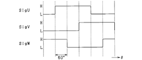
- the magnetic pole position detection sensor 19 (for example, a hall sensor, more specifically, a hall IC) is provided corresponding to each phase, and outputs an output signal as shown in FIG. 3 according to the rotation of the rotor. To do. Thereby, the rotation angle (electrical angle ⁇ ) of the starting generator 12 can be grasped at an electrical angle interval of 60 °.
- output signals corresponding to the U, V, and W phases are shown as SigU, SigV, and SigW.
- the control device 20 is configured mainly with a microcomputer.
- the control device 20 controls the inter-terminal voltage of the battery 14 (hereinafter referred to as the battery voltage VDC) detected by the voltage sensor 18 to the target voltage Vtgt when the starter generator 12 is operated as a generator. Therefore, the inverter 13 is operated.
- the control device 20 calculates U, V, and W phase applied voltages Vu, Vv, and Vw for driving the starter generator 12 by a known three-phase 180 ° energization method based on the detection values of the various sensors. To do.
- the control device 20 turns on / off each of the switches Sup to Swn based on the calculated applied voltage.
- the upper arm switch and the lower arm switch are alternately turned on at every electrical angle of 180 ° for each phase, and the switching of the upper arm switch to the off state is performed at an electrical angle of 120 for each phase. Switching is performed so as to shift by °.
- control system does not include a current sensor for detecting the direct current IDC flowing in the electric path connecting the battery 14 and the inverter 13. For this reason, in this embodiment, the control apparatus 20 performs the electric current estimation process which estimates the direct current IDC.
- the current estimation process will be described.
- the control device 20 includes a speed calculation unit 21, an applied voltage calculation unit 22, a current estimation unit 23 (corresponding to “current estimation unit”), and an SOC calculation unit 24 (corresponding to “charge rate calculation unit”).
- the speed calculation unit 21 calculates the rotational speed ⁇ (electrical angular speed) of the starter generator 12 based on the output signal of the magnetic pole position detection sensor 19 (specifically, for example, the interval of the logical inversion timing of the output signal).
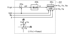
- the applied voltage calculation unit 22 calculates each phase applied voltage Vu, Vv, Vw, which is a command value of the applied voltage for each phase winding.
- the voltage deviation calculation unit 22 a (corresponding to “voltage deviation calculation unit”) calculates the voltage deviation ⁇ V by subtracting the battery voltage VDC from the target voltage Vtgt of the battery 14.
- Phase calculation unit 22b (corresponding to “phase calculation means”) calculates voltage phase ⁇ , which is the phase of output voltage vector Vn of inverter 13, based on voltage deviation ⁇ V.
- the voltage phase ⁇ is calculated as an operation amount for performing feedback control of the voltage deviation ⁇ V to 0.
- the voltage phase ⁇ may be calculated by proportional control or proportional integral control using the voltage deviation ⁇ V as an input.
- the voltage phase ⁇ when the voltage vector Vn rotates clockwise with the positive q axis in the dq coordinate system as a reference is defined as a positive value.
- rotating the voltage vector Vn clockwise is referred to as retarding the voltage phase ⁇
- rotating the voltage vector Vn counterclockwise is referred to as advancing the voltage phase ⁇ . I will do it.
- the voltage amplitude that is the amplitude of the voltage vector Vn is assumed to be “Vamp”.
- the phase calculation unit 22b calculates the voltage phase ⁇ within a range from 0 ° to a specified phase when the starter generator 12 is operated as a generator.
- the prescribed phase is set to a value larger than 0 ° and smaller than 90 °.
- the prescribed phase is set to 30 ° due to restrictions on the mounting position of the magnetic pole position detection sensor 19 on the stator teeth.
- the prescribed phase is not limited to 30 °, and may be set to other values as long as the value is larger than 0 ° and smaller than 90 °.
- the voltage phase ⁇ calculated by the phase calculation unit 22b is input to the tracking control unit 220c.
- the follow-up control unit 220c performs a predetermined process on the input voltage phase ⁇ and outputs it.
- the follow-up control unit 220c will be described in detail later.
- the voltage phase ⁇ output from the follow-up control unit 220c is input to the rectangular wave signal generation unit 22d.
- the rectangular wave signal generation unit 22d is configured to apply each phase applied voltage Vu, Vv, Vw as a rectangular wave signal based on the input voltage phase ⁇ , the battery voltage VDC, and the output signal of the magnetic pole position detection sensor 19 (not shown). Is calculated. Specifically, first, the voltage amplitude Vamp is calculated by multiplying the battery voltage VDC by the voltage utilization rate.
- the voltage utilization rate is the ratio of the command value of the voltage amplitude Vamp to the battery voltage VDC. In the present embodiment, the voltage utilization rate is set to the upper limit “0.78”.
- each phase applied voltage Vu, Vv, Vw for 180 ° energization is calculated.
- the rectangular wave signal generation unit 22 d outputs the calculated phase applied voltages Vu, Vv, Vw to the inverter 13.
- the rectangular wave signal generation unit 22d generates a d-axis voltage Vd that is a d-axis component of the voltage vector Vn and a q-axis voltage that is a q-axis component of the voltage vector Vn based on the voltage phase ⁇ and the voltage amplitude Vamp. Vq is calculated.
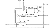
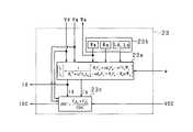
- the current estimating unit 23 calculates the rotational speed ⁇ calculated by the speed calculating unit 21, the battery voltage VDC, and the d and q axis voltages Vd and Vq calculated by the rectangular wave signal generating unit 22d. Is used to estimate the direct current IDC.
- the current estimation process performed by the current estimation unit 23 will be described with reference to FIG.
- the dq axis current estimation unit 23a receives the rotation speed ⁇ and estimates the d and q axis currents id and iq based on the following equation (eq1).
- d, q-axis inductances Ld, Lq, winding resistance Ra, and induced voltage constant ⁇ a are fixed values determined in advance by the specifications of the rotating electrical machine to be controlled, experimental data, etc.
- a device constant storage unit 23b for example, a non-volatile memory. Since the winding resistance Ra and the induced voltage constant ⁇ a are temperature dependent, a table or map relating the winding resistance Ra and the induced voltage constant ⁇ a to the temperature is created in advance, and the table or map is used. The winding resistance Ra and the induced voltage constant ⁇ a may be set.
- the direct current estimation unit 23c uses the battery voltage VDC, the d and q axis currents id and iq estimated by the dq axis current estimation unit 23a, and the d and q axis voltages Vd and Vq calculated by the rectangular wave signal generation unit 22d.
- DC current IDC is estimated based on the following equation (eq3).
- the SOC calculation unit 24 calculates the charging rate SOC of the battery 14 based on the integrated value of the DC current IDC estimated by the DC current estimation unit 23c.
- the calculated charging rate SOC is used for various processes of the vehicle, for example.
- FIG. 6 shows changes in the estimated value of the DC current IDC, the measured value of the DC current, the d-axis current id, and the engine speed N.
- FIG. 6 shows that after time t1, the operating state of the engine 11 shifts to the idle operating state, the d-axis current shifts from a negative value to a positive value, and the estimation error ⁇ Ierr increases.
- the estimated error ⁇ Ierr increases when the d-axis current is a positive value because the actual d-axis inductance is reduced due to the influence of abrupt magnetic saturation, and the actual d-axis inductance is stored in the device constant storage unit 23b. This is because it greatly deviates from the d-axis inductance Ld.
- the engine rotational speed the rotational speed of the crankshaft 11a
- the voltage phase ⁇ reaches the specified phase
- the rotational speed ⁇ of the starter generator 12 is low and the starter generator 12 is induced. Since the voltage is small, the d-axis current becomes a positive value and the estimation error ⁇ Ierr is likely to increase.
- the tracking control unit 220c performs a process of setting the d-axis current to 0.
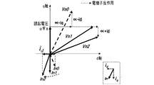
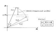
- the reason why the d-axis current can be reduced to 0 with reference to FIG.
- each current vector corresponding to each voltage vector Vn0, Vn1, Vn2 is indicated by “In0, In1, In2”.
- the d and q axis armature reactions occur depending on the positional relationship between the induced voltage vector and the voltage vector.
- the current vector is a current vector In0 in which a positive d-axis current flows due to the d-axis armature reaction.
- the d-axis armature reaction disappears, so the current vector becomes a current vector In1 such that the d-axis current becomes zero.
- the sign of the d-axis current is inverted, and the current vector becomes a current vector In2 in which a negative d-axis current flows.
- the phase of the current vector changes according to the deviation between the q-axis component of the voltage vector and the induced voltage. Using this fact, the d-axis current is set to 0 under the situation where the current estimation process is performed.
- FIG. 8 illustrates processing performed by the follow-up control unit 220c. This process is repeatedly executed at a predetermined processing cycle, for example.
- step S10 it is determined whether or not a clutch meet state is present. If it is determined in step S10 that the clutch meet state is not established (the clutch is disengaged), the process proceeds to step S11 where the calculation rotational speed ⁇ c is set to one combustion cycle (720 ° C. A) of the engine 11 as shown in FIG. ) Is the minimum value ⁇ min of the rotational speed ⁇ .
- step S11 the calculation rotational speed ⁇ c is set to one combustion cycle (720 ° C. A) of the engine 11 as shown in FIG. ) Is the minimum value ⁇ min of the rotational speed ⁇ .
- This process is provided in view of the fact that an estimation error of the direct current IDC is likely to occur in the clutch disengaged state. That is, in the clutch meet state, the rotational shaft of the starter generator 12 is connected to the drive wheels 17, so that the rotational inertia increases and the rotational fluctuation of the starter generator 12 is suppressed.
- the rotating shaft of the starter generator 12 is not connected to the drive wheels 17, so that the rotational inertia is reduced, and the rotation fluctuation of the starter generator 12 accompanying the combustion control of the engine 11 is reduced. growing.
- the induced voltage “ ⁇ c ⁇ ⁇ a” is calculated in step S13, which will be described later, using the rotational speed ⁇ for each time, the calculated induced voltage may be larger than the actual induced voltage. In this case, even if the q-axis voltage Vq follows the calculated induced voltage, the d-axis current cannot be reduced to 0 or less.
- the minimum value ⁇ min of the rotational speed in one combustion cycle of the engine 11 is used for calculation of the induced voltage.
- step S10 determines whether the clutch is in the engaged state. If it is determined in step S10 that the clutch is in the engaged state, the process proceeds to step S12, where the calculation rotational speed ⁇ c is set to the latest rotational speed ⁇ i grasped from the output signal of the magnetic pole position detection sensor 19.
- step S13 the voltage amplitude Vamp, the calculation rotational speed ⁇ c, the voltage phase ⁇ calculated by the phase calculation unit 22b, and the induced voltage constant ⁇ a stored in the device constant storage unit 23b are input, and the following equation (eq4 ) To calculate the induced voltage deviation INDEX.
- the voltage amplitude Vamp may be calculated by multiplying the battery voltage VDC by the upper limit value “0.78” of the voltage utilization rate. Then, it is determined whether the induced voltage deviation INDEX is larger than zero. This process is a process for determining whether or not the d-axis current is larger than zero.
- step S14 the voltage phase ⁇ is set as an operation amount for feedback-controlling the induced voltage deviation INDEX to 0 on condition that the voltage phase ⁇ is not more than the specified phase while expanding the specified phase from 30 ° to 90 °. calculate.
- the larger the induced voltage deviation INDEX the larger the voltage phase ⁇ is calculated. That is, in order to control the q-axis voltage Vq to the induced voltage, the voltage phase ⁇ calculated by the phase calculation unit 22b is corrected.
- the processing of this step includes “induced voltage calculation means” and “phase change means”.
- step S15 when the voltage phase ⁇ exceeds the guard value ⁇ , a guard process for limiting the voltage phase ⁇ with the guard value ⁇ is performed.
- the guard value ⁇ is set to be smaller as the q-axis voltage is larger than the voltage phase when the induced voltage matches the induced voltage and the calculation rotational speed ⁇ c is higher.
- the guard value ⁇ is set to a value of 90 ° or less.
- This process is a process for avoiding an increase in the q-axis current due to an excessive retardation of the voltage phase ⁇ and an excessive increase in the generated power of the starting generator 12.
- FIG. 10 shows an example in which the voltage vector is changed from Vn1 to Vn2 by the process of step S14, but the voltage vector is changed to Vn3 by the guard process.
- the processing of this step includes “guard value calculation means”.
- step S13 it is determined that the d-axis current is 0 or less.
- the power generation efficiency of the starter generator 12 may decrease due to a decrease in power generation due to a decrease in q-axis current and an increase in loss due to an increase in d-axis current. is there. Therefore, a decrease in power generation efficiency can be suppressed by setting the upper limit to 90 °.
- the clutch disengaged state In the clutch disengaged state, the minimum value ⁇ min of the rotational speed in one combustion cycle of the engine 11 was used for calculation of the induced voltage.
- the clutch disengaged state is a state where the induced voltage is low and the fluctuation of the rotational speed is large. Even under this circumstance, the q-axis voltage Vq can be accurately set to the induced voltage or less, and the d-axis current can be set to 0 or less. Thereby, the estimation error of the direct current IDC can be accurately suppressed even before the clutch meet.
- the voltage phase ⁇ is limited by the guard value ⁇ . For this reason, it is possible to prevent an excessive retardation of the voltage phase ⁇ and, in turn, avoid an excessive increase in generated power.
- the follow-up control unit 220c calculates the induced voltage deviation INDEX, and determines that the d-axis current is larger than 0 when the calculated induced voltage deviation INDEX is larger than zero.
- the follow-up control unit 220c may determine whether the d-axis current id estimated by the dq-axis current estimation unit 23a is greater than 0, or the induced voltage deviation INDEX or the d-axis current id is 0. It may be determined whether the value is larger than the value exceeding.
- the starter generator 12 is not limited to a permanent magnet type synchronous machine, but may be a field winding type synchronous machine having a rotor with a field winding, for example.
- the starter generator 12 is not limited to the Y-connected one, and may be a ⁇ -connected one, for example.
- the clutch 16 is not limited to an automatic centrifugal clutch, and may be an intermittent clutch configured to be switchable between a clutch meet state and a clutch disengaged state by a user's clutch lever operation, for example.
- the driving method of the starter generator 12 is not limited to the three-phase 180 ° energization method, and may be another energization method such as a three-phase 120 ° energization method.
- 4 is not limited to the upper limit value, and may be a value less than the upper limit value.
- step S14 in FIG. 8 the voltage phase ⁇ may be changed so that the induced voltage deviation INDEX is feedback-controlled to a specified value other than zero. That is, the voltage phase ⁇ may be changed so that the d-axis current is a specified current less than a specified value.
- the voltage phase ⁇ calculated by the phase calculation unit 22b may be input to the rectangular wave signal generation unit 22d as it is.
- the rotational speed used for calculating the induced voltage may be calculated as follows. Specifically, for each combustion cycle (720 ° CA) of the engine 11, the rotation speed when the rotation angle position of the crankshaft 11a becomes a preset rotation angle position (hereinafter referred to as a rotation speed at a predetermined angle position) is calculated. To do. Then, based on the calculated rotational speed at the predetermined angular position and the minimum value of the rotational speed of one combustion cycle determined in advance by experiments or the like, the minimum rotational speed value ⁇ min used for calculating the induced voltage is calculated. Also good.
- the difference or deviation value between the rotational speed at the predetermined angular position and the minimum value of the rotational speed determined in advance through experiments or the like is calculated, and the rotational speed at the predetermined angular position is calculated based on the calculated difference or deviation value.
- the minimum value ⁇ min may be calculated by correction.
- the minimum value ⁇ min of the rotational speed in one combustion cycle of the engine 11 is used for calculation of the induced voltage.
- the present invention is not limited to this.
- a rotational speed ⁇ slightly higher than the minimum value ⁇ min may be used.
- the power conversion circuit is not limited to a three-phase inverter. In short, any other power conversion circuit may be used as long as it is a power conversion circuit that can convert the AC voltage output from the starter generator 12 into a DC voltage and apply it to the battery 14.
- the application target of the current estimation apparatus according to the first embodiment of the present invention is not limited to a motorcycle, and may be other vehicles such as an automobile.
- the control system according to each embodiment of the present invention shown in FIG. 2 does not include a current sensor that detects the DC current IDC flowing in the electrical path connecting the battery 14 and the inverter 13. For this reason, also in the second embodiment, the control device 20 performs a current estimation process for estimating the DC current IDC.
- the current estimation device according to the second embodiment as shown in FIG.
- the direct current IDC (charging current) that flows from the high potential side terminals of the upper arm switches Sup, Svp, Swp to the positive terminal of the battery 14 is used.
- Is defined as a positive value
- the DC current IDC discharge current flowing from the positive terminal of the battery 14 to the high potential side terminals of the upper arm switches Sup, Svp, Swp is defined as a negative value.
- the rotation angle (electrical angle ⁇ ) of the starter generator 12 can be grasped at an electrical angle interval of 60 °.
- output signals corresponding to the U, V, and W phases are indicated by SigU, SigV, and SigW.
- the control device 20 in the second embodiment includes a speed calculation unit 21, an applied voltage calculation unit 22, a current estimation unit 23 (corresponding to “current estimation unit”), and an SOC calculation unit 24 (corresponding to “charge rate calculation unit”). It has.
- the speed calculation unit 21 calculates the rotational speed ⁇ (electrical angular speed) of the starter generator 12 based on the output signal of the magnetic pole position detection sensor 19 (specifically, for example, the interval of the logical inversion timing of the output signal).
- the voltage phase ⁇ may be calculated by proportional control or proportional integral control using the voltage deviation ⁇ V as an input.
- the voltage phase ⁇ when the voltage vector Vn rotates clockwise with the positive q axis in the dq coordinate system as a reference is defined as a positive value.
- rotating the voltage vector Vn clockwise is referred to as retarding the voltage phase ⁇
- rotating the voltage vector Vn counterclockwise is referred to as advancing the voltage phase ⁇ . I will do it.
- the voltage amplitude that is the amplitude of the voltage vector Vn is assumed to be “Vamp”.
- the phase calculation unit 22b calculates the voltage phase ⁇ within a range from 0 ° to a specified phase when the starter generator 12 is operated as a generator.
- the prescribed phase is set to a value larger than 0 ° and smaller than 90 °.
- the prescribed phase is set to 30 ° due to restrictions on the mounting position of the magnetic pole position detection sensor 19 on the stator teeth.
- the prescribed phase is not limited to 30 °, and may be set to other values as long as the value is larger than 0 ° and smaller than 90 °.
- the voltage phase ⁇ calculated by the phase calculation unit 22b is input to the rectangular wave signal generation unit 22c.
- the rectangular wave signal generator 22c is configured to apply each phase applied voltage Vu, Vv, Vw as a rectangular wave signal based on the input voltage phase ⁇ , the battery voltage VDC, and the output signal of the magnetic pole position detection sensor 19 (not shown). Is calculated. Specifically, first, the voltage amplitude Vamp is calculated by multiplying the battery voltage VDC by the voltage utilization rate Mr.
- the voltage utilization rate Mr is the ratio of the command value of the voltage amplitude Vamp to the battery voltage VDC.
- the voltage utilization rate Mr is basically set to the upper limit value Mlimit (0.78).
- each phase applied voltage Vu, Vv, Vw for 180 ° energization is calculated.
- the rectangular wave signal generation unit 22 c outputs the calculated phase applied voltages Vu, Vv, Vw to the inverter 13.
- the rectangular wave signal generation unit 22c generates a d-axis voltage Vd that is a d-axis component of the voltage vector Vn and a q-axis voltage that is a q-axis component of the voltage vector Vn based on the voltage phase ⁇ and the voltage amplitude Vamp. Vq is calculated.
- the rectangular wave signal generation unit 22c includes “voltage control means”.
- the current estimation unit 23 is based on the rotation speed ⁇ calculated by the speed calculation unit 21, the battery voltage VDC, and the d and q-axis voltages Vd and Vq calculated by the rectangular wave signal generation unit 22 c. Then, the direct current IDC is estimated.
- the current estimation process performed by the current estimation unit 23 will be described with reference to FIG.
- the dq-axis current estimation unit 23a receives the rotation speed ⁇ and estimates the d and q-axis currents id and iq based on the equation (eq1) used in the description of the first embodiment.
- Equation (eq1) “Ra” represents an armature winding resistance, “Ld” and “Lq” represent d and q axis inductances, and “ ⁇ a” represents an induced voltage constant.
- the equation (eq1) is derived by imposing a condition that the transient phenomenon is ignored with respect to the equation (eq2) representing the voltage equation of the permanent magnet type synchronous machine and modifying the d and q axis currents id and iq. Can do.
- equation (eq2) used in the description of the first embodiment “p” represents a differential operator.
- d, q-axis inductances Ld, Lq, winding resistance Ra, and induced voltage constant ⁇ a are fixed values determined in advance by the specifications of the rotating electrical machine to be controlled, experimental data, etc.
- a device constant storage unit 23b for example, a non-volatile memory. Since the winding resistance Ra and the induced voltage constant ⁇ a are temperature dependent, a table or map relating the winding resistance Ra and the induced voltage constant ⁇ a to the temperature is created in advance, and the table or map is used. The winding resistance Ra and the induced voltage constant ⁇ a may be set.
- the direct current estimation unit 23c uses the battery voltage VDC, the d and q axis currents id and iq estimated by the dq axis current estimation unit 23a, and the d and q axis voltages Vd and Vq calculated by the rectangular wave signal generation unit 22c.
- the DC current IDC is estimated based on the equation (eq3) used in the description of the first embodiment.
- the SOC calculation unit 24 calculates the charge rate SOC of the battery 14 based on the integrated value of the DC current IDC estimated by the DC current estimation unit 23c.
- the calculated charging rate SOC is used for various processes of the vehicle, for example.
- the estimated error ⁇ Ierr increases when the d-axis current is a positive value because the actual d-axis inductance is reduced due to the influence of abrupt magnetic saturation, and the actual d-axis inductance is stored in the device constant storage unit 23b. This is because it greatly deviates from the d-axis inductance Ld.
- the engine rotational speed the rotational speed of the crankshaft 11a
- the voltage phase ⁇ reaches the specified phase
- the rotational speed ⁇ of the starter generator 12 is low and the starter generator 12 is induced. Since the voltage is small, the d-axis current becomes a positive value and the estimation error ⁇ Ierr is likely to increase.
- the rectangular wave signal generation unit 22c when the d-axis current becomes a positive value under the situation where the current estimation process is performed, the rectangular wave signal generation unit 22c performs the process of setting the d-axis current to 0.
- the reason why the d-axis current can be reduced to 0 using FIG. 13 will be described, and then the processing performed by the rectangular wave signal generation unit 22c will be described.
- FIG. 13 shows voltage vectors Vn0, Vn1, and Vn2 when the voltage phase ⁇ becomes the specified phase (30 °).
- the voltage vector Vn0 indicates a voltage vector when the q-axis component is higher than the induced voltage “ ⁇ ⁇ ⁇ a”
- the voltage vector Vn1 indicates the voltage vector when the q-axis component matches the induced voltage.
- the voltage vector Vn2 indicates a voltage vector when the q-axis component is lower than the induced voltage.
- each current vector corresponding to each voltage vector Vn0, Vn1, Vn2 is indicated by “In0, In1, In2”.
- the d and q axis armature reactions occur depending on the positional relationship between the induced voltage vector and the voltage vector.
- the current vector is a current vector In0 in which a positive d-axis current flows due to the d-axis armature reaction.
- the d-axis armature reaction disappears, so the current vector becomes a current vector In1 such that the d-axis current becomes zero.
- the sign of the d-axis current is inverted, and the current vector becomes a current vector In2 in which a negative d-axis current flows.
- the phase of the current vector changes according to the deviation between the q-axis component of the voltage vector and the induced voltage. Using this fact, the d-axis current is set to 0 under the situation where the current estimation process is performed.
- step S140 it is determined whether or not a clutch meet state is present. If it is determined in step S140 that the clutch meet state is not established (the clutch is disengaged), the process proceeds to step S141, where the calculation rotational speed ⁇ c is set to the value of the engine 11 as shown in FIGS. The minimum value ⁇ min of the rotational speed ⁇ in one combustion cycle (720 ° C. A) is set. This process is provided in view of the fact that an estimation error of the direct current IDC is likely to occur in the clutch disengaged state.
- the minimum value ⁇ min of the rotational speed in one combustion cycle of the engine 11 is used for calculation of the induced voltage.
- step S140 determines whether the clutch meet state is reached. If it is determined in step S140 that the clutch meet state is reached, the process proceeds to step S142, and the calculation rotational speed ⁇ c is set to the latest rotational speed ⁇ i grasped from the output signal of the magnetic pole position detection sensor 19.
- step S143 the voltage amplitude Vamp, the calculation rotational speed ⁇ c, the voltage phase ⁇ calculated by the phase calculation unit 22b, and the induced voltage constant ⁇ a stored in the device constant storage unit 23b are input, and Based on the equation (eq4) used in the description, an induced voltage deviation INDEX is calculated.
- the voltage amplitude Vamp may be calculated by multiplying the battery voltage VDC by the upper limit value Mlimit (0.78) of the voltage utilization rate. Then, it is determined whether the induced voltage deviation INDEX is larger than zero.
- This process is a process for determining whether or not the d-axis current is larger than zero.
- the process of step S143 includes “induced voltage calculation means”.
- step S143 If an affirmative determination is made in step S143, it is determined that the d-axis current is greater than 0, and the process proceeds to step S144.
- step S144 a duty ratio correction amount ⁇ Duty ( ⁇ 0) is calculated as an operation amount for performing feedback control of the induced voltage deviation INDEX to 0.
- the process of step S144 includes “duty ratio setting means”.
- the process of step S144 will be described.
- step S144 is based on 180 ° energization control, but also makes the q-axis voltage follow the induced voltage by combining 180 ° energization control with duty control (also referred to as PWM control).
- duty control also referred to as PWM control.
- the timing chart of FIG. 15 corresponds to the timing chart of FIG.
- the ON period defined by the 180 ° energization control is set as the ON operation possible period. Repeat the operation.
- FIG. 16 shows an example of how the voltage amplitude Vamp is adjusted.
- the larger the voltage phase ⁇ the larger the time ratio correction amount ⁇ Duty for matching the q-axis voltage with the induced voltage is set.
- the voltage vector Vn2 is shown in a state where the voltage phase exceeds the specified phase (30 °).
- step S145 based on the voltage phase ⁇ , the duty ratio correction amount ⁇ Duty, the battery voltage VDC, and the output signal of the magnetic pole position detection sensor 19 (not shown), the applied voltages Vu and Vv of the respective phases are obtained by the method described above in the rectangular wave signal generation unit 22c. , Vw is calculated.
- the voltage usage rate Mr for calculating the voltage amplitude Vamp may be calculated by the following equation (eq5), for example.
- the duty ratio correction amount ⁇ Duty is set to zero.
- the q-axis voltage Vq is made to follow the induced voltage “ ⁇ c ⁇ ⁇ a” by decreasing the voltage amplitude Vamp.
- the voltage amplitude Vamp is reduced by performing duty control based on 180 ° energization control. For this reason, it can be avoided that the actual d-axis inductance greatly deviates from the predetermined d-axis inductance Ld used for current estimation. Thereby, the estimation error of DC current IDC can be suppressed suitably. Therefore, it is possible to avoid a decrease in the calculation accuracy of the charging rate SOC of the battery 14.
- the second embodiment may be modified as follows.
- the rectangular wave signal generation unit 22c calculates the induced voltage deviation INDEX, and determines that the d-axis current is larger than 0 when the calculated induced voltage deviation INDEX is larger than 0. Not exclusively. For example, the rectangular wave signal generation unit 22c may determine whether or not the d-axis current id estimated by the dq-axis current estimation unit 23a is greater than 0, or the induced voltage deviation INDEX or the d-axis current id. It may be determined whether or not is larger than a value exceeding 0.
- the starter generator 12 is not limited to a permanent magnet type synchronous machine, but may be a field winding type synchronous machine having a rotor with a field winding, for example.
- the starter generator 12 is not limited to the Y-connected one, and may be a ⁇ -connected one, for example.
- the upper arm switch is turned on / off according to the time ratio in the period in which the upper arm switch can be turned on, so that the voltage amplitude Vamp is decreased to make the q-axis voltage follow the induced voltage. Absent.
- the voltage amplitude Vamp may be lowered by turning on and off the lower arm switch according to the time ratio during the on-operation period of the lower arm switch.
- the method for causing the q-axis voltage to follow the induced voltage is not limited to the method for reducing the duty ratio.
- the voltage amplitude Vamp may be decreased by reducing the voltage between the terminals of the battery 14.
- the driving method of the starter generator 12 is not limited to the three-phase 180 ° energization method, and may be another energization method such as a three-phase 120 ° energization method.
- FIG. 17 shows basic 120 ° energization control
- FIG. 18 shows control in which duty control is combined with 120 ° energization control.
- the basic voltage usage rate used in the rectangular wave signal generation unit 22c is not limited to the upper limit value Mlimit but may be a value less than the upper limit value.
- step S144 of the flowchart of FIG. 14 the duty ratio correction amount ⁇ Duty may be calculated so that the induced voltage deviation INDEX is feedback-controlled to a specified value other than zero. That is, the voltage amplitude Vamp may be manipulated so that the d-axis current is a specified current less than a specified value.
- the rotational speed used for calculating the induced voltage may be calculated as follows. Specifically, for each combustion cycle (720 ° CA) of the engine 11, the rotation speed when the rotation angle position of the crankshaft 11a becomes a preset rotation angle position (hereinafter referred to as a rotation speed at a predetermined angle position) is calculated. To do. Then, based on the calculated rotational speed at the predetermined angular position and the minimum value of the rotational speed of one combustion cycle determined in advance by experiments or the like, the minimum rotational speed value ⁇ min used for calculating the induced voltage is calculated. Also good.
- the difference or deviation value between the rotational speed at the predetermined angular position and the minimum value of the rotational speed determined in advance through experiments or the like is calculated, and the rotational speed at the predetermined angular position is calculated based on the calculated difference or deviation value.
- the minimum value ⁇ min may be calculated by correction.
- the minimum value ⁇ min of the rotational speed in one combustion cycle of the engine 11 is used for calculating the induced voltage.
- the present invention is not limited to this, and for example, immediately before the minimum value ⁇ min or A rotational speed ⁇ that is slightly higher than the minimum value ⁇ min, such as the rotational speed ⁇ immediately after, may be used.
- the power conversion circuit is not limited to a three-phase inverter. In short, any other power conversion circuit may be used as long as it is a power conversion circuit that can convert the AC voltage output from the starter generator 12 into a DC voltage and apply it to the battery 14.
- the application target of the current estimation device according to the second embodiment is not limited to a motorcycle, but may be other vehicles such as an automobile. .
- the motorcycle 10 shown in FIG. 1 includes an engine 11, a starting generator 12 as a rotating electric machine, an inverter 13 as a power conversion circuit, and a DC power source.
- a battery 14, a transmission 15, a clutch 16, drive wheels 17, and a control device 20 are provided.
- the engine 11 is an in-vehicle main machine of the motorcycle 10, and in each embodiment, is a single cylinder four-stroke engine.
- the combustion control of the engine 11 may be performed by another control device (not shown) different from the control device 20, or may be performed by the control device 20.
- the starter / generator 12 is electrically connected to the battery 14 via the inverter 13.
- the inverter 13 includes a series connection body of upper arm switches Sup, Svp, Swp and lower arm switches Sun, Svn, Swn.
- a first end of a U-phase winding (not shown) of the starter / generator 12 is connected to a connection point between the U-phase upper and lower arm switches Sup and Sun, and a connection point between the V-phase upper and lower arm switches Svp and Svn.
- a first end of a V-phase winding (not shown) is connected to a connection point between the W-phase upper and lower arm switches Swp and Swn.
- the second ends of the U, V, and W phase windings are short-circuited. That is, in this embodiment, the starter generator 12 is Y-connected.
- the positive terminal of the battery 14 is connected to the high potential side terminal of each upper arm switch Sup, Svp, Swp, and the negative terminal of the battery 14 is connected to the low potential side terminal of each lower arm switch Sun, Svn, Swn. Is connected.
- each of the switches Sup to Swn for example, a voltage-controlled semiconductor switching element such as a MOS-FET or IGBT can be used. Further, the freewheel diodes Dup to Dwn are connected in antiparallel to the switches Sup to Swn.
- Each freewheel diode Dup to Dwn may be a body diode or an external diode when each switch is a MOS-FET, for example.
- the control system includes a voltage sensor 18 and a magnetic pole position detection sensor 19.
- the voltage sensor 18 detects the voltage between the terminals of the battery 14.
- the magnetic pole position detection sensor 19 (for example, a hall sensor, more specifically, a hall IC) is provided corresponding to each phase, and outputs an output signal as shown in FIG. 3 according to the rotation of the rotor. Output.
- the magnetic pole position (electrical angle ⁇ ) of the starting generator 12 can be grasped at an electrical angle interval of 60 °.
- FIG. 3 shows output signals SigU, SigV, and SigW corresponding to the U, V, and W phases.
- the output signals of the voltage sensor 18 and the magnetic pole position detection sensor 19 are input to the control device 20.
- the control device 20 is configured mainly with a microcomputer.
- the control device 20 controls the inter-terminal voltage of the battery 14 (hereinafter referred to as the battery voltage VDC) detected by the voltage sensor 18 to the target voltage Vtgt when the starter generator 12 is operated as a generator. Therefore, the inverter 13 is operated.
- the control device 20 calculates U, V, and W phase applied voltages Vu, Vv, and Vw for driving the starter generator 12 by a known three-phase 180 ° energization method based on the detection values of the various sensors. To do.
- the control device 20 turns on / off the switches Sup to Swn based on the calculated applied voltage.
- control system does not include a current sensor that detects the DC current IDC flowing in the electrical path connecting the battery 14 and the inverter 13. For this reason, in this embodiment, the control apparatus 20 performs the electric current estimation process which estimates the direct current IDC.
- the current estimation process will be described.
- the control device 20 includes a speed calculation unit 21, an applied voltage calculation unit 22, a current estimation unit 23 (corresponding to “current estimation unit”), and an SOC calculation unit 24 (corresponding to “charge rate calculation unit”).
- the speed calculation unit 21 calculates the rotational speed ⁇ (electrical angular speed) of the starter generator 12 based on the output signal of the magnetic pole position detection sensor 19 (specifically, for example, the interval of the logical inversion timing of the output signal).
- the applied voltage calculation unit 22 calculates each phase applied voltage Vu, Vv, Vw, which is a command value of the applied voltage for each phase winding.
- the voltage deviation calculation unit 22 a (corresponding to “voltage deviation calculation unit”) calculates the voltage deviation ⁇ V by subtracting the battery voltage VDC from the target voltage Vtgt of the battery 14.
- Phase calculation unit 22b (corresponding to “phase calculation means”) calculates voltage phase ⁇ , which is the phase of output voltage vector Vn of inverter 13, based on voltage deviation ⁇ V.
- the voltage phase ⁇ is calculated as an operation amount for performing feedback control of the voltage deviation ⁇ V to 0.
- the voltage phase ⁇ may be calculated by proportional control or proportional integral control using the voltage deviation ⁇ V as an input.
- the voltage phase ⁇ when the voltage vector Vn rotates clockwise with the positive q axis in the dq coordinate system as a reference is defined as a positive value.
- rotating the voltage vector Vn clockwise is referred to as retarding the voltage phase ⁇
- rotating the voltage vector Vn counterclockwise is referred to as advancing the voltage phase ⁇ . I will do it.
- the voltage amplitude that is the amplitude of the voltage vector Vn is assumed to be “Vamp”.
- the phase calculation unit 22b calculates the voltage phase ⁇ within a range from 0 ° to a specified phase when the starter generator 12 is operated as a generator.
- the prescribed phase is set to a value larger than 0 ° and smaller than 90 °.
- the prescribed phase is set to 30 ° due to restrictions on the mounting position of the magnetic pole position detection sensor 19 on the stator teeth.
- the prescribed phase is not limited to 30 °, and may be set to other values as long as the value is larger than 0 ° and smaller than 90 °.
- the voltage phase ⁇ calculated by the phase calculation unit 22b is input to the rectangular wave signal generation unit 22c.
- the rectangular wave signal generation unit 22c calculates the applied voltages Vu, Vv, and Vw as rectangular wave signals based on the input voltage phase ⁇ , the battery voltage VDC, and the output signal of the magnetic pole position detection sensor 19. To do. Specifically, first, the voltage amplitude Vamp is calculated by multiplying the battery voltage VDC by the voltage utilization rate Mr. Here, the voltage utilization rate Mr is the ratio of the command value of the voltage amplitude Vamp to the battery voltage VDC. Then, based on the calculated voltage amplitude Vamp and voltage phase ⁇ , each phase applied voltage Vu, Vv, Vw for 180 ° energization is calculated. The rectangular wave signal generation unit 22 c outputs the calculated phase applied voltages Vu, Vv, Vw to the inverter 13.
- phase applied voltages Vu, Vv, Vw (on / off operation states of the switches Sup to Swn) are maintained over a period of an electrical angle of 60 °. That is, each phase application voltage Vu, Vv, Vw is updated at an electrical angle interval of 60 °. This is because the detection period of the electrical angle ⁇ by the magnetic pole position detection sensor 19 is 60 ° as described above.
- the voltage utilization rate Mr is set to the basic utilization rate Mb, and the basic utilization rate Mb is set to a value greater than 0 and less than the upper limit utilization rate Mlimit (0.78). Yes.
- calculation modes of the applied voltages Vu, Vv, and Vw of each phase will be described with reference to FIGS. 11 and 15.
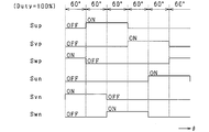
- FIG. 11 shows the operation states of the switches Sup to Swn (corresponding to the applied voltages Vu, Vv, Vw) when the voltage utilization rate Mr is set to the upper limit utilization rate Mlimit.
- the duty ratio Duty when the voltage utilization rate Mr becomes the upper limit utilization rate Mlimit is 100%.
- the duty ratio Duty is the ratio (Ton / Tsw) of the on operation time Ton to one cycle of the on / off operation of each switch (one switching period Tsw).
- the voltage utilization rate Mr is set to a basic utilization rate Mb that is less than the upper limit utilization rate Mlimit.
- the operation states of the switches Sup to Swn are actually based on 180 ° energization control, as shown in FIG. 15, but combined 180 ° energization control with duty control (also referred to as PWM control). It will be a thing.
- the ON period defined by the 180 ° energization control is set as the ON operation possible period, and the ON / OFF operation is performed within this ON operation possible period. repeat.
- the voltage amplitude Vamp can be adjusted by adjusting the duty ratio Duty. Specifically, the voltage amplitude Vamp decreases as the duty ratio becomes smaller.
- the basic utilization rate Mb in the present embodiment is a value corresponding to the duty ratio of 90%.
- the rectangular wave signal generation unit 22c further generates a d-axis voltage Vd that is a d-axis component of the voltage vector Vn and a q-axis voltage that is a q-axis component of the voltage vector Vn based on the voltage phase ⁇ and the voltage amplitude Vamp.
- Vq is calculated.
- the voltage phase ⁇ used to calculate the d and q-axis voltages Vd and Vq is a value corrected by the process when a voltage phase operation process to be described later is performed.
- the voltage amplitude Vamp used for calculating the d and q-axis voltages Vd and Vq is a value corrected by the processing when the voltage amplitude operation processing described later is performed.
- the current estimation unit 23 is based on the rotation speed ⁇ calculated by the speed calculation unit 21, the battery voltage VDC, and the d and q-axis voltages Vd and Vq calculated by the rectangular wave signal generation unit 22 c. Then, the direct current IDC is estimated.
- the current estimation process performed by the current estimation unit 23 will be described with reference to FIG.
- the dq-axis current estimation unit 23a estimates the d and q-axis currents id and iq based on the equation (eq1) used in the description of the first and second embodiments, with the rotational speed ⁇ as an input. To do.
- Equation (eq1) “Ra” represents an armature winding resistance, “Ld” and “Lq” represent d and q axis inductances, and “ ⁇ a” represents an induced voltage constant.
- the equation (eq1) is derived by imposing a condition that the transient phenomenon is ignored with respect to the equation (eq2) representing the voltage equation of the permanent magnet type synchronous machine and modifying the d and q axis currents id and iq. Can do.
- equation (eq2) used in the description of the first embodiment and the second embodiment “p” represents a differential operator.
- d, q-axis inductances Ld, Lq, winding resistance Ra, and induced voltage constant ⁇ a are fixed values determined in advance by the specifications of the rotating electrical machine to be controlled, experimental data, etc.
- a device constant storage unit 23b for example, a non-volatile memory. Since the winding resistance Ra and the induced voltage constant ⁇ a are temperature dependent, a table or map relating the winding resistance Ra and the induced voltage constant ⁇ a to the temperature is created in advance, and the table or map is used. The winding resistance Ra and the induced voltage constant ⁇ a may be set.
- the direct current estimation unit 23c uses the battery voltage VDC, the d and q axis currents id and iq estimated by the dq axis current estimation unit 23a, and the d and q axis voltages Vd and Vq calculated by the rectangular wave signal generation unit 22d.
- the DC current IDC is estimated based on the equation (eq3) used in the description of the first embodiment and the second embodiment.
- FIG. 6 shows changes in the estimated value of the DC current IDC, the measured value of the DC current, the d-axis current id, and the engine speed N.
- FIG. 6 shows that after time t1, the operating state of the engine 11 shifts to the idle operating state, the d-axis current shifts from a negative value to a positive value, and the estimation error ⁇ Ierr increases.
- the estimated error ⁇ Ierr increases when the d-axis current is a positive value because the actual d-axis inductance is reduced due to the influence of abrupt magnetic saturation, and the actual d-axis inductance is stored in the device constant storage unit 23b. This is because it greatly deviates from the d-axis inductance Ld.
- the engine rotational speed the rotational speed of the crankshaft 11a
- the voltage phase ⁇ reaches the specified phase
- the rotational speed ⁇ of the starter generator 12 is low and the starter generator 12 is induced. Since the voltage is small, the d-axis current becomes a positive value and the estimation error ⁇ Ierr is likely to increase.
- the rectangular wave signal generation unit 22c when the d-axis current is a positive value under the situation where the current estimation process is performed, the rectangular wave signal generation unit 22c performs a process for setting the d-axis current to 0.
- the reason why the d-axis current can be set to 0 will be described with reference to FIGS. 7 and 13, and the processing performed by the rectangular wave signal generation unit 22 c will be described.
- each current vector corresponding to each voltage vector Vn0, Vn1, Vn2 is indicated by “In0, In1, In2”.
- the d and q axis armature reactions occur depending on the positional relationship between the induced voltage vector and the voltage vector.
- the current vector is a current vector In0 in which a positive d-axis current flows due to the d-axis armature reaction.
- the q-axis component of the voltage vector Vn1 matches the induced voltage
- the d-axis armature reaction disappears, so the current vector becomes a current vector In1 such that the d-axis current becomes zero.
- the sign of the d-axis current is inverted, and the current vector becomes a current vector In2 in which a negative d-axis current flows.
- FIG. 13 shows voltage vectors Vn0, Vn1, and Vn2 when the voltage phase ⁇ becomes the specified phase (30 °).
- the voltage vector Vn0 is a voltage vector when the q-axis component is higher than the induced voltage “ ⁇ ⁇ ⁇ a”
- the voltage vector Vn1 is a voltage vector when the q-axis component matches the induced voltage. is there.
- the voltage vector Vn2 is a voltage vector when the q-axis component is lower than the induced voltage.
- each current vector corresponding to each voltage vector Vn0, Vn1, Vn2 is indicated by “In0, In1, In2”.
- the d and q axis armature reactions occur depending on the positional relationship between the induced voltage vector and the voltage vector.
- the current vector is a current vector In0 in which a positive d-axis current flows due to the d-axis armature reaction.
- the d-axis armature reaction disappears, so the current vector becomes a current vector In1 such that the d-axis current becomes zero.
- the sign of the d-axis current is inverted, and the current vector becomes a current vector In2 in which a negative d-axis current flows.
- the phase of the current vector changes according to the deviation between the q-axis component of the voltage vector and the induced voltage.
- the d-axis current can be made zero by operating the voltage phase ⁇ and the voltage amplitude Vamp. Using this, the d-axis current is set to 0 under the situation where the current estimation process is performed.
- FIG. 21 illustrates processing performed by the rectangular wave signal generation unit 22c. This process is repeatedly executed on condition that the current estimation process is performed.
- step S210 it is determined whether or not the d-axis current id estimated by the dq-axis current estimation unit 23a is greater than zero. This process is a process for determining whether or not the current estimation accuracy is reduced.
- step S210 If a negative determination is made in step S210, it is determined that the current estimation accuracy does not decrease and the process proceeds to step S211.
- step S211 normal-time voltage feedback control for calculating the applied voltages Vu, Vv, and Vw for each phase based on the voltage phase ⁇ calculated by the phase calculator 22b, the battery voltage VDC, and the output signal of the magnetic pole position detection sensor 19. I do.
- the voltage utilization rate Mr used to calculate the applied voltages Vu, Vv, and Vw is set to the basic utilization rate Mb, and the applied voltages Vu,
- the voltage phase ⁇ used for calculating Vv and Vw is set to a value calculated by the phase calculation unit 22b.
- the rotational shaft of the starter generator 12 is connected to the drive wheels 17, so that the rotational inertia increases and the rotational fluctuation of the starter generator 12 is suppressed.
- the rotating shaft of the starter generator 12 is not connected to the drive wheels 17, so that the rotational inertia is reduced, and the rotation fluctuation of the starter generator 12 accompanying the combustion control of the engine 11 is reduced. growing.
- the induced voltage “ ⁇ c ⁇ ⁇ a” is calculated in step S215 to be described later using the rotational speed ⁇ at each time, the calculated induced voltage may be larger than the actual induced voltage. In this case, even if the q-axis voltage Vq follows the calculated induced voltage, the d-axis current cannot be reduced to 0 or less.
- the minimum value ⁇ min of the rotational speed in one combustion cycle of the engine 11 is used for calculation of the induced voltage.
- step S212 determines whether the clutch is in the engaged state. If it is determined in step S212 that the clutch is in the engaged state, the process proceeds to step S214, and the calculation rotational speed ⁇ c is set to the latest rotational speed ⁇ i grasped from the output signal of the magnetic pole position detection sensor 19.
- step S215 the voltage amplitude Vamp, the calculation rotational speed ⁇ c, the voltage phase ⁇ calculated by the phase calculation unit 22b, and the induced voltage constant ⁇ a stored in the device constant storage unit 23b are input, and the first embodiment and The induced voltage deviation INDEX is calculated based on the equation (eq4) used in the description of the second embodiment.
- the voltage amplitude Vamp may be calculated by multiplying the battery voltage VDC by the basic utilization rate Mb.
- the processing in step S215 includes “induced voltage calculation means” and “induced deviation calculation means”.
- step S216 it is determined whether or not the battery voltage VDC is less than the specified voltage Vth (> 0). This process is a process for determining whether or not the battery 14 is insufficiently charged.
- step S217 If an affirmative determination is made in step S217, the process proceeds to step S218 to determine whether or not the calculation rotational speed ⁇ c is equal to or higher than the lower limit speed ⁇ 0.
- the lower limit speed ⁇ ⁇ b> 0 is set to a rotational speed (for example, 100 rpm) that cannot be taken as a motorcycle during combustion control of the engine 11.
- This process is a process for avoiding an excessive retardation of the voltage phase ⁇ . That is, when the rotational speed is excessively low, the amount of retardation of the voltage phase ⁇ becomes excessively large.
- step S218 If a negative determination is made in step S218, the voltage phase operation process is prohibited, and the process proceeds to step S211 to perform normal voltage feedback control. On the other hand, if an affirmative determination is made in step S218, the process proceeds to step S219 to perform voltage phase operation processing.
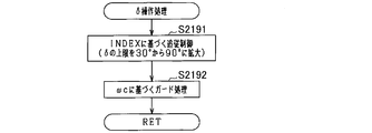
- this process will be described with reference to FIG.
- step S2191 in FIG. 22 the induced voltage deviation INDEX is feedback-controlled to 0 on the condition that the voltage phase ⁇ is not more than the specified phase while the specified phase is expanded from 30 ° to 90 °.
- the voltage phase ⁇ is calculated as an operation amount for this.
- the larger the induced voltage deviation INDEX the larger the voltage phase ⁇ is calculated. That is, the voltage phase ⁇ calculated by the phase calculation unit 22b is corrected so as to control the q-axis voltage to the induced voltage.
- the specified phase after the upper limit expansion is 90 ° because if the voltage phase ⁇ is excessively retarded, the q-axis current decreases and the power generation amount decreases or the d-axis current increases. This is to avoid an increase in loss.
- a guard process for limiting the voltage phase ⁇ with the guard value ⁇ is performed.
- the guard value ⁇ is set to be smaller as the q-axis voltage is larger than the voltage phase when the induced voltage matches the induced voltage and the calculation rotational speed ⁇ c is higher.
- the guard value ⁇ is set to a value of 90 ° or less.
- This process is a process for avoiding an increase in the q-axis current due to an excessive retardation of the voltage phase ⁇ and an excessive increase in the generated power of the starting generator 12.
- FIG. 10 shows an example in which the voltage vector is changed from Vn1 to Vn2 by the process of step S2191, but the voltage vector is changed to Vn3 by the guard process.
- the processing of this step includes “guard value calculation means”.
- step S211 calculates the applied voltages Vu, Vv, and Vw of each phase. Specifically, based on the value obtained by correcting the voltage phase ⁇ calculated by the phase calculation unit 22b by the voltage phase manipulation process, the battery voltage VDC, and the output signal of the magnetic pole position detection sensor 19, each phase applied voltage Vu, Vv, Vw is calculated.
- step S220 a voltage amplitude operation process is performed.
- a duty ratio correction amount ⁇ Duty ( ⁇ 0) is calculated as an operation amount for performing feedback control of the induced voltage deviation INDEX to 0.
- the duty ratio correction amount ⁇ Duty is calculated to be larger as the induced voltage deviation INDEX is a negative value and the absolute value thereof is larger.
- the processing in step S220 includes “duty ratio setting means”.
- the processing in this step S220 is based on the 180 ° energization control, but the 180 ° energization control is combined with the duty control to make the q-axis voltage follow the induced voltage. It is processing.
- the final time ratio “90% + ⁇ Duty” is set by adding and correcting the time ratio correction amount ⁇ Duty calculated in step S220 to the time ratio Duty 90% corresponding to the basic usage rate Mb.
- each phase applied voltage Vu is based on the voltage phase ⁇ corrected by the voltage phase manipulation process, the final duty ratio “90% + ⁇ Duty”, the battery voltage VDC, and the output signal of the magnetic pole position detection sensor 19. , Vv, Vw are calculated.
- the voltage utilization rate Mr used to calculate the voltage amplitude Vamp may be calculated by the following equation (eq6), for example.
- FIG. 21 Next, the processing described in FIG. 21 will be further described with reference to vector diagrams shown in FIGS. 23 (a), (b), and (c).
- FIG. 23A is a diagram before the execution of the voltage phase operation process and the voltage amplitude operation process.
- the voltage phase ⁇ 1 is a specified phase (30 °).
- the voltage phase is retarded to ⁇ 2 by the voltage phase manipulation process, so that the induced voltage deviation INDEX is less than the negative predetermined value “ ⁇ K”, that is, the q-axis voltage is induced. The value is less than the voltage.
- the q-axis voltage is made to follow the induced voltage by the voltage amplitude operation process.
- the q-axis voltage when the q-axis voltage follows the induced voltage, the q-axis voltage is first brought close to the induced voltage by the retardation of the voltage phase ⁇ .
- the retarding operation of the voltage phase ⁇ increases the generated power of the starting generator 12.
- the operation of the voltage amplitude Vamp for causing the q-axis voltage to follow the induced voltage is performed prior to the operation of retarding the voltage phase ⁇ , the generated power is reduced due to the decrease of the voltage amplitude Vamp.
- the operation amount of the voltage amplitude Vamp is small. Therefore, first, the q-axis voltage is brought close to the induced voltage without reducing the generated power by operating the voltage phase ⁇ . Thereby, the reduction
- the control period ⁇ T1 of the voltage phase operation processing is also set at intervals of 60 °.
- the control period ⁇ T2 of the voltage amplitude operation process is set to a period shorter than the control period ⁇ T1 of the voltage phase operation process because the voltage phase ⁇ is not required in this process.
- the control period ⁇ T2 of the voltage amplitude operation process is set to one control period of the control device 20. For this reason, the update frequency of the voltage amplitude Vamp by the voltage amplitude operation process is higher than the update frequency of the voltage phase ⁇ by the voltage phase operation process.
- the tracking accuracy of the q-axis voltage to the induced voltage by the voltage amplitude operation processing is higher than the tracking accuracy by the voltage phase operation processing. For this reason, first, after the d-axis current is brought close to 0 by the retardation of the voltage phase ⁇ , the voltage amplitude Vamp with high tracking accuracy is operated to quickly follow the q-axis voltage to the induced voltage with high accuracy. Can do.
- the q-axis voltage is made to follow the induced voltage by increasing the voltage amplitude Vamp, the q-axis voltage is brought close to the induced voltage by the retardation of the voltage phase ⁇ prior to the operation of the voltage amplitude Vamp.
- decrease of the electric power generation of the starter generator 12 accompanying suppressing the estimation error of an electric current can also be suppressed.
- the power generation efficiency of the starter generator 12 may decrease due to a decrease in power generation due to a decrease in q-axis current and an increase in loss due to an increase in d-axis current. is there. Therefore, a decrease in power generation efficiency can be suppressed by setting the upper limit to 90 °.
- the clutch disengaged state the minimum value ⁇ min of the rotational speed in one combustion cycle of the engine 11 was used for calculation of the induced voltage.
- the clutch disengaged state is a state where the induced voltage is low and the fluctuation of the rotational speed is large. Even under this condition, the q-axis voltage can be made to accurately follow the induced voltage, and the d-axis current can be made zero. Thereby, the estimation error of the direct current IDC can be accurately suppressed even before the clutch meet.
- step S210 in FIG. 21 is a process of determining whether the d-axis current id is greater than a value exceeding 0, a process of determining whether the induced voltage deviation INDEX is greater than 0, or an induced voltage deviation. You may replace with the process which judges whether INDEX is larger than the value exceeding 0.
- the 21 may be replaced with a process for determining whether or not the d-axis current id estimated by the dq-axis current estimator 23a is larger than a predetermined negative value.
- the guard process in step S2192 in FIG. 22 may be removed.
- the voltage vector is rotated in the retarding direction until the q-axis voltage becomes less than the induced voltage, and then the voltage amplitude Vamp is increased to cause the q-axis voltage to follow the induced voltage.
- the voltage amplitude Vamp may be decreased to cause the q-axis voltage to follow the induced voltage.
- the basic usage rate Mb may be set to the upper limit usage rate Mlimit, for example.
- the 21 may be replaced with a process for determining whether or not the charge rate SOC of the battery 14 calculated by the SOC calculation unit 24 is less than a predetermined SOC.
- the voltage phase ⁇ may be changed so that the induced voltage deviation INDEX is feedback-controlled to a non-zero value Ith. That is, the voltage phase ⁇ may be changed so that the d-axis current is a specified current that is not 0 and is less than the value Ith.
- step S220 in FIG. 21 the duty ratio correction amount ⁇ Duty may be calculated so that the induced voltage deviation INDEX is feedback-controlled to a value Ith that is not zero. That is, the voltage amplitude Vamp may be manipulated so that the d-axis current is a specified current that is not 0 and is less than the value Ith.
- the voltage amplitude Vamp is decreased in order to make the q-axis voltage follow the induced voltage by turning the lower arm switch on and off according to the time ratio in the period during which the lower arm switch can be turned on.
- the voltage amplitude Vamp may be decreased by performing an on / off operation of the upper arm switch according to a time ratio in a period during which the upper arm switch can be turned on.
- the method for increasing the voltage amplitude Vamp for causing the q-axis voltage to follow the induced voltage is not limited to increasing the duty ratio.
- the voltage amplitude Vamp may be increased by increasing the voltage between the terminals of the battery 14.
- the starter generator 12 is not limited to a permanent magnet type synchronous machine, but may be a field winding type synchronous machine having a rotor with a field winding, for example.
- the starter generator 12 is not limited to the Y-connected one, and may be a ⁇ -connected one, for example.
- the driving method of the starter generator 12 is not limited to the three-phase 180 ° energization method, and may be another energization method such as a three-phase 120 ° energization method.
- FIG. 17 shows basic 120 ° energization control
- FIG. 18 shows control in which duty control is combined with 120 ° energization control.
- the magnetic pole position detection sensor is not limited to the Hall sensor as long as the magnetic pole position can be detected, and other sensors may be used.
- the rotational speed used to calculate the induced voltage may be calculated as follows. Specifically, for each combustion cycle (720 ° CA) of the engine 11, the rotation speed when the rotation angle position of the crankshaft 11a becomes a preset rotation angle position (hereinafter referred to as a rotation speed at a predetermined angle position) is calculated. To do. Then, based on the calculated rotational speed at the predetermined angular position and the minimum value of the rotational speed of one combustion cycle determined in advance by experiments or the like, the minimum rotational speed value ⁇ min used for calculating the induced voltage is calculated. Also good.
- the difference or deviation value between the rotational speed at the predetermined angular position and the minimum value of the rotational speed determined in advance through experiments or the like is calculated, and the rotational speed at the predetermined angular position is calculated based on the calculated difference or deviation value.
- the minimum value ⁇ min may be calculated by correction.
- the minimum value ⁇ min of the rotational speed in one combustion cycle of the engine 11 is used for calculation of the induced voltage.
- the present invention is not limited to this.
- a rotational speed ⁇ that is slightly higher than the minimum value ⁇ min, such as the rotational speed ⁇ , may be used.
- the power conversion circuit is not limited to a three-phase inverter. In short, any other power conversion circuit may be used as long as it is a power conversion circuit that can convert the AC voltage output from the starter generator 12 into a DC voltage and apply it to the battery 14.
- the clutch 16 is not limited to an automatic centrifugal clutch, and may be an intermittent clutch configured to be switchable between a clutch meet state and a clutch disengaged state by a user's clutch lever operation, for example.
- the application target of the current estimation device according to the third embodiment is not limited to a motorcycle, but other vehicles such as automobiles. It may be.
Landscapes
- Engineering & Computer Science (AREA)
- Power Engineering (AREA)
- Control Of Eletrric Generators (AREA)
- Control Of Ac Motors In General (AREA)
Abstract
始動発電機を制御対象とする制御装置は、電流推定部と、印加電圧算出部とを備えている。電流推定部は、始動発電機の予め定められたd軸インダクタンスに基づいて、バッテリとインバータとの間に流れる電流を推定する。印加電圧算出部は、dq座標系におけるd軸電流が0よりも大きくなることを条件として、インバータの電圧ベクトルのq軸成分「Vamp×cosδ」を始動発電機の誘起電圧成分「ωc×Ψa」に追従させるべく、電圧ベクトルの位相である電圧位相δを、電圧ベクトルの振幅である電圧振幅Vampを、あるいは電圧位相δを操作した後、電圧振幅Vampを操作する。
Description
本発明は、電力変換回路、及び前記電力変換回路に対する通電操作により直流電源と電力伝達を行う回転電機を備えるシステムに適用される電流推定装置に関する。
従来、下記特許文献1に見られるように、回転電機の電圧方程式に基づいてdq座標系におけるd,q軸電流を算出する制御装置が知られている。詳しくは、この制御装置では、d軸インダクタンスに基づいてd,q軸電流を算出している。
ところで、電力変換回路、及び電力変換回路に対する通電操作により直流電源と電力伝達を行う回転電機を備えるシステムにおいて、直流電源と電力変換回路との間に流れる電流を推定する技術がある。この技術では、予め定められたd軸インダクタンスに基づいて、d,q軸電流を算出し、算出されたd,q軸電流に基づいて、直流電源と電力変換回路との間に流れる電流を推定する。
ここで、d軸インダクタンスは、d軸電流が0よりも大きくなる場合に生じる急激な磁気飽和の影響によって変化する。この場合、実際のd軸インダクタンスが予め定められたd軸インダクタンスから大きくずれ、直流電源と電力変換回路との間に流れる電流の推定誤差が大きくなる懸念がある。なお、上述した急激な磁気飽和が発生する場合におけるd軸インダクタンスの特性を正確に把握することも考えられる。ただし、この特性を正確に把握することは困難である。
本発明は、直流電源と電力変換回路との間に流れる電流の推定誤差を好適に抑制できる電流推定装置を提供することを主たる目的とする。
以下、上記課題を解決するための手段、及びその作用効果について記載する。
本発明に係る電流推定装置は、電力変換回路、及び前記電力変換回路に対する通電操作により直流電源と電力伝達を行う回転電機とを備えるシステムに適用される。電流推定装置は、前記回転電機の予め定められたd軸インダクタンスに基づいて、前記直流電源と前記電力変換回路との間に流れる電流を推定する電流推定手段と、前記回転電機のdq座標系におけるd軸電流が0よりも大きい所定の値となることを条件として、前記電力変換回路の電圧ベクトルのq軸成分を前記回転電機の誘起電圧成分に追従させるべく前記電圧ベクトルの位相である電圧位相を操作する位相操作手段とを備えることを特徴とする。
電圧ベクトルのq軸成分が誘起電圧成分と一致する状態においては、d軸電流が0となる。この点に鑑み、上記発明に係る電流推定装置では、d軸電流が0よりも大きい所定の値となることを条件として、電圧位相の操作により、電圧ベクトルのq軸成分を回転電機の誘起電圧成分に追従させる。このため、実際のd軸インダクタンスが、電流推定に用いられる予め定められたd軸インダクタンスから大きくずれることを回避できる。これにより、電流推定手段による電流の推定誤差を好適に抑制することができる。
本発明に係る他の電流推定装置は、電力変換回路、及び前記電力変換回路に対する通電操作により直流電源と電力伝達を行う回転電機を備えるシステムに適用される。この電流推定装置は、前記回転電機の予め定められたd軸インダクタンスに基づいて、前記直流電源と前記電力変換回路との間に流れる電流を推定する電流推定手段と、前記回転電機のdq座標系におけるd軸電流が0よりも大きい所定の値となることを条件として、前記電力変換回路の電圧ベクトルのq軸成分を前記回転電機の誘起電圧成分に追従させるべく前記電圧ベクトルの振幅である電圧振幅を操作する振幅操作手段とを備えることを特徴とする。
電圧ベクトルのq軸成分が誘起電圧成分と一致する状態においては、d軸電流が0となる。この点に鑑み、本願発明に係る電流推定装置では、d軸電流が0よりも大きい所定の値となることを条件として、電圧振幅の操作により、電圧ベクトルのq軸成分を回転電機の誘起電圧成分に追従させる。このため、実際のd軸インダクタンスが、電流推定に用いられる予め定められたd軸インダクタンスから大きくずれることを回避できる。これにより、電流推定手段による電流の推定誤差を好適に抑制することができる。
本発明に係る他の電流推定装置は、電力変換回路、及び前記電力変換回路に対する通電操作により直流電源と電力伝達を行う回転電機を備えるシステムに適用される。この電流推定装置は、前記電力変換回路の電圧ベクトルの振幅を電圧振幅とし、前記電圧ベクトルの位相を電圧位相とし、前記回転電機の予め定められたd軸インダクタンスに基づいて、前記直流電源と前記電力変換回路との間に流れる電流を推定する電流推定手段と、前記回転電機のdq座標系におけるd軸電流が0よりも大きい所定の値となることを条件として、前記電圧ベクトルのq軸成分と前記回転電機の誘起電圧成分との偏差が0よりも大きい規定値未満の値となるまで、正のq軸を基準として前記電圧ベクトルを時計まわりに回転させる方向に前記電圧位相を操作する位相操作手段と、前記d軸電流が前記所定の値となることを条件として、前記q軸成分と前記誘起電圧成分との偏差が前記規定値未満となる領域において、前記電圧ベクトルのq軸成分を前記誘起電圧成分に追従させるべく前記電圧振幅を操作する振幅操作手段とを備えることを特徴とする。
電圧ベクトルのq軸成分が誘起電圧成分と一致する状態においては、d軸電流が0となる。この点に鑑み、上記発明では、まず、d軸電流が0よりも大きい所定の値となることを条件として、q軸成分と誘起電圧成分との偏差が規定値未満の値となるまで、正のq軸を基準として電圧ベクトルを時計まわりに回転させる方向に電圧位相を操作する。また、電圧振幅の操作により、q軸成分を誘起電圧成分に追従させる。このため、実際のd軸インダクタンスが、電流推定に用いられる予め定められたd軸インダクタンスから大きくずれることを回避できる。これにより、電流推定手段による電流の推定誤差を好適に抑制することができる。
さらに、上記電流推定装置は、q軸成分と誘起電圧成分との偏差が規定値未満となる領域において、q軸成分を誘起電圧成分に追従させるべく電圧振幅を操作する。電圧ベクトルを時計まわりに回転させる方向への電圧位相の操作は、回転電機の発電電力を増大させる。これに対し、電圧位相の操作に先立ち、q軸成分を誘起電圧成分に追従させるための電圧振幅の操作を行うと、発電電力を減少させることがある。このため、発電電力の減少を抑制する上では、電圧振幅の操作量は小さい方がよい。そこで、q軸成分と誘起電圧成分との偏差が規定値未満となる領域において電圧振幅を操作することにより、発電電力を減少させることなくq軸成分を誘起電圧成分に近づける。これにより、電流の推定誤差を抑制することに伴う発電電力の減少を抑制することができる。
ここで、前記システムでは、前記回転電機の磁極位置を規定周期毎に検出する磁極位置検出手段を備え、前記電圧位相を0°よりも大きくてかつ90°よりも小さい規定位相以下にすることを条件として前記回転電機を制御するための前記電圧位相を算出する位相算出手段と、前記位相算出手段によって算出された前記電圧位相と、前記磁極位置検出手段によって検出された前記磁極位置とに基づいて、前記回転電機の印加電圧を制御する電圧制御手段とをさらに備え、前記位相操作手段は、前記規定周期を制御周期として、前記偏差が前記規定値未満の値となるまで前記位相算出手段によって算出された前記電圧位相を操作し、前記振幅操作手段は、前記規定周期よりも短い周期を制御周期として、前記q軸成分を前記誘起電圧成分に追従させるための前記電圧振幅の操作を、前記印加電圧を調整することで行うこととしてもよい。
磁極位置検出手段による磁極位置の検出周期が規定周期とされているため、位相操作手段の制御周期も規定周期に設定されている。一方、電圧位相の情報を要しない振幅操作手段の制御周期は、位相操作手段の制御周期よりも短い周期に設定されている。このため、振幅操作手段によるq軸成分の誘起電圧成分への追従精度は、位相操作手段による追従精度よりも高い。したがって、q軸成分と誘起電圧成分との偏差が規定値未満となる領域において追従精度の高い電圧振幅を操作することで、q軸成分を誘起電圧成分に迅速かつ高精度に追従させることができる。その結果、電流の推定誤差をいっそう好適に抑制することができる。
[第1実施形態]以下、車載主機としてエンジンを搭載した自動2輪車(オートバイ)に、第1実施形態に係る電流推定装置を適用した場合について、図面を参照しつつ説明する。
図1に示すように、自動2輪車10は、エンジン11、回転電機としての始動発電機12、電力変換回路としてのインバータ13、直流電源としてのバッテリ14、変速装置15、クラッチ16、駆動輪17、及び制御装置20を備えている。エンジン11は、自動2輪車10の車載主機であり、本実施形態では、単気筒4ストロークエンジンである。なお、エンジン11の燃焼制御は、制御装置20とは異なる他の制御装置(図示せず)によって行われてもよいし、制御装置20によって行われてもよい。
エンジン11の出力軸(以下、クランク軸11a)の第1端には、変速装置15の入力側(具体的には例えば、エンジン側プーリ)が連結されている。本実施形態では、変速装置15として、自動変速装置(具体的には、無段変速装置)を用いている。変速装置15の出力側(具体的には例えば、駆動輪側プーリ)には、クラッチ16と、図示しない2次減速機構とを介して、駆動輪17が連結されている。
クラッチ16は、変速装置15の出力側と駆動輪17との間の動力を伝達可能な状態(以下、クラッチミート状態)、及び変速装置15の出力側と駆動輪17との間の動力が遮断される状態(以下、クラッチ遮断状態)のいずれかに切り替え可能に構成されている。本実施形態では、クラッチ16として、自動遠心クラッチを用いている。本実施形態にかかる自動遠心クラッチは、変速装置15の出力側に接続されたクラッチシュー、クラッチスプリング、及び駆動輪17側に接続されたクラッチアウターを備えている。この構成において、エンジン11の低回転時においては、クラッチスプリングの弾性力によってクラッチシューが縮径し、クラッチシューとクラッチアウターとが非接触状態とされる。これにより、クラッチ遮断状態とされる。一方、エンジン11の回転速度が上昇してクラッチシューに作用する遠心力が増大すると、クラッチスプリングの弾性力に打ち勝ってクラッチシューが拡径し、クラッチシューがクラッチアウターに接触した状態となる。これにより、クラッチミート状態とされる。特に本実施形態では、クランク軸11aの回転速度が所定回転速度(>0)以上となった場合にクラッチミート状態とされるようにクラッチ16が構成されている。本実施形態において、上記所定回転速度は、エンジン11のアイドル回転速度よりも高い回転速度に設定されている。
クランク軸11aの第2端には、始動発電機12を構成するロータの回転軸が直結されている。このため、始動発電機12のロータは、クランク軸11aと一体に回転する。始動発電機12は、電動機(エンジン始動用のスタータ)及び発電機として動作可能であり、エンジンブロックに取り付けられている。本実施形態において、始動発電機12は、3相交流の永久磁石型同期機であり、永久磁石が設けられた上記ロータと、各相巻線が巻回されたステータとを備えている。
続いて、図2を用いて、始動発電機12の制御システムについて説明する。始動発電機12は、インバータ13を介して、バッテリ14に電気的に接続されている。インバータ13は、上アームスイッチSup,Svp,Swpと下アームスイッチSun,Svn,Swnとの直列接続体を備えている。U相上,下アームスイッチSup,Sunの接続点には、始動発電機12の図示しないU相巻線の第1端が接続され、V相上,下アームスイッチSvp,Svnの接続点には、図示しないV相巻線の第1端が接続され、W相上,下アームスイッチSwp,Swnの接続点には、図示しないW相巻線の第1端が接続されている。U,V,W相巻線の第2端同士は、短絡されている。すなわち、本実施形態では、始動発電機12として、Y結線されたものを用いている。各上アームスイッチSup,Svp,Swpの高電位側の端子には、バッテリ14の正極端子が接続され、各下アームスイッチSun,Svn,Swnの低電位側の端子には、バッテリ14の負極端子が接続されている。
ちなみに、各スイッチSup~Swnとしては、例えば、MOS-FETやIGBT等の電圧制御形の半導体スイッチング素子を用いることができる。また、各スイッチSup~Swnには、各フリーホイールダイオードDup~Dwnが逆並列に接続されている。なお、各フリーホイールダイオードDup~Dwnは、各スイッチが例えばMOS-FETの場合、ボディダイオードであってもよいし、外付けのダイオードであってもよい。
制御システムは、電圧センサ18と、磁極位置検出センサ19とを備えている。本実施形態において、電圧センサ18は、バッテリ14の端子間電圧を検出する。また、磁極位置検出センサ19(例えば、ホールセンサであり、より具体的にはホールIC)は、各相に対応して設けられ、ロータの回転に応じて図3に示すような出力信号を出力する。これにより、始動発電機12の回転角度(電気角θ)を電気角60°間隔で把握することができる。なお、図3には、U,V,W相に対応する出力信号をSigU,SigV,SigWで示した。
先の図2の説明に戻り、電圧センサ18及び磁極位置検出センサ19の出力信号は、制御装置20に入力される。制御装置20は、マイコンを主体として構成されている。本実施形態において、制御装置20は、始動発電機12を発電機として動作させる場合において、電圧センサ18によって検出されたバッテリ14の端子間電圧(以下、バッテリ電圧VDC)を目標電圧Vtgtに制御すべく、インバータ13を操作する。詳しくは、制御装置20は、上記各種センサの検出値に基づき、始動発電機12を周知の3相180°通電方式で駆動させるためのU,V,W相印加電圧Vu,Vv,Vwを算出する。制御装置20は、算出された印加電圧に基づいて、各スイッチSup~Swnをオンオフ操作する。これにより、各相のそれぞれについて上アームスイッチと下アームスイッチとが電気角180°毎に交互にオン状態とされてかつ、上アームスイッチのオフ状態への切り替えが相毎に電気角で互いに120°だけずれるようにスイッチングが行われる。
ここで、図2に示す本願発明の実施形態に係る制御システムは、バッテリ14とインバータ13とを接続する電気経路に流れる直流電流IDCを検出する電流センサを備えていない。このため、本実施形態において、制御装置20は、直流電流IDCを推定する電流推定処理を行う。以下、始動発電機12の制御について説明した後、電流推定処理について説明する。
制御装置20は、速度算出部21、印加電圧算出部22、電流推定部23(「電流推定手段」に相当)、及びSOC算出部24(「充電率算出手段」に相当)を備えている。速度算出部21は、磁極位置検出センサ19の出力信号(具体的には例えば、出力信号の論理反転タイミングの間隔)に基づいて、始動発電機12の回転速度ω(電気角速度)を算出する。
印加電圧算出部22は、各相巻線に対する印加電圧の指令値である各相印加電圧Vu,Vv,Vwを算出する。以下、図4を用いて、印加電圧算出部22について説明する。印加電圧算出部22において、電圧偏差算出部22a(「電圧偏差算出手段」に相当)は、バッテリ14の目標電圧Vtgtからバッテリ電圧VDCを減算することで、電圧偏差ΔVを算出する。位相算出部22b(「位相算出手段」に相当)は、電圧偏差ΔVに基づいて、インバータ13の出力電圧ベクトルVnの位相である電圧位相δを算出する。本実施形態では、電圧偏差ΔVを0にフィードバック制御するための操作量として電圧位相δを算出する。具体的には例えば、電圧偏差ΔVを入力とする比例制御又は比例積分制御によって電圧位相δを算出すればよい。ここで、本実施形態では、dq座標系における正のq軸を基準として、時計まわりに電圧ベクトルVnが回転する場合の電圧位相δを正の値で定義する。特に本実施形態では、電圧ベクトルVnを時計まわりに回転させることを、電圧位相δを遅角させると称し、電圧ベクトルVnを反時計まわりに回転させることを、電圧位相δを進角させると称すこととする。なお、電圧ベクトルVnの振幅である電圧振幅を「Vamp」とする。
位相算出部22bは、始動発電機12を発電機として動作させる場合、電圧位相δを0°から規定位相までの範囲内で算出する。規定位相は、0°よりも大きくてかつ90°よりも小さい値に設定されている。なお、本実施形態では、ステータティースへの磁極位置検出センサ19の取付位置の制約等から、規定位相を30°に設定した。ただし、規定位相としては、30°に限らず、0°よりも大きくてかつ90°未満の値であれば、他の値に設定してもよい。
位相算出部22bによって算出された電圧位相δは、追従制御部220cに入力される。追従制御部220cは、入力された電圧位相δに所定の処理を施して出力する。追従制御部220cについては、後に詳述する。
追従制御部220cから出力された電圧位相δは、矩形波信号生成部22dに入力される。矩形波信号生成部22dは、入力された電圧位相δと、バッテリ電圧VDCと、図示しない磁極位置検出センサ19の出力信号とに基づいて、矩形波信号としての各相印加電圧Vu,Vv,Vwを算出する。詳しくは、まず、バッテリ電圧VDCに電圧利用率を乗算することにより、電圧振幅Vampを算出する。ここで、電圧利用率とは、バッテリ電圧VDCに対する電圧振幅Vampの指令値の比率のことである。本実施形態において、電圧利用率は、その上限値「0.78」に設定されている。そして、算出された電圧振幅Vampと、電圧位相δとに基づいて、180°通電のための各相印加電圧Vu,Vv,Vwを算出する。矩形波信号生成部22dは、算出された各相印加電圧Vu,Vv,Vwをインバータ13に対して出力する。
また、矩形波信号生成部22dは、電圧位相δと、電圧振幅Vampとに基づいて、電圧ベクトルVnのd軸成分であるd軸電圧Vdと、電圧ベクトルVnのq軸成分であるq軸電圧Vqとを算出する。
先の図2の説明に戻り、電流推定部23は、速度算出部21によって算出された回転速度ω、バッテリ電圧VDC、及び矩形波信号生成部22dによって算出されたd,q軸電圧Vd,Vqに基づいて、直流電流IDCを推定する。以下、図5を用いて、電流推定部23の行う電流推定処理について説明する。電流推定部23において、dq軸電流推定部23aは、回転速度ωを入力として、以下の式(eq1)に基づいてd,q軸電流id,iqを推定する。


直流電流推定部23cは、バッテリ電圧VDC、dq軸電流推定部23aによって推定されたd、q軸電流id,iq、及び矩形波信号生成部22dによって算出されたd,q軸電圧Vd,Vqを入力として、以下の式(eq3)に基づいて直流電流IDCを推定する。

ところで、d軸電流が正の値となる場合には、図6に示すように、直流電流IDCの推定誤差ΔIerrが大きくなる。ここで、図6は、直流電流IDCの推定値、直流電流の実測値、d軸電流id、及びエンジン回転速度Nの推移を示す。図6には、時刻t1以降においてエンジン11の運転状態がアイドル運転状態に移行し、d軸電流が負の値から正の値に移行して推定誤差ΔIerrが増大することを示した。d軸電流が正の値となる場合に推定誤差ΔIerrが増大するのは、急激な磁気飽和の影響によって実際のd軸インダクタンスが小さくなり、実際のd軸インダクタンスが、機器定数記憶部23bに記憶されているd軸インダクタンスLdから大きくずれるためである。特に、エンジン回転速度(クランク軸11aの回転速度)がアイドル回転速度付近である場合において電圧位相δが規定位相に達しているときには、始動発電機12の回転速度ωが低く始動発電機12の誘起電圧が小さいことから、d軸電流が正の値になって推定誤差ΔIerrが増大しやすい。
そこで本実施形態では、電流推定処理が行われている状況下において、d軸電流が正の値となる場合、d軸電流を0とする処理を追従制御部220cにおいて行う。以下、図7を用いてd軸電流を0とできる理由を説明した後、追従制御部220cの行う処理について説明する。
図7に、電圧位相δが規定位相(30°)となる場合の電圧ベクトルを「Vn0」にて示し、q軸電圧Vqが誘起電圧「ω×Ψa」と一致する場合の電圧ベクトルを「Vn1」にて示し、電圧ベクトルVn1よりも電圧位相δが大きい場合の電圧ベクトルを「Vn2」にて示す。また、各電圧ベクトルVn0,Vn1,Vn2に対応する各電流ベクトルを「In0,In1,In2」にて示す。
図示されるように、誘起電圧ベクトルと電圧ベクトルとの位置関係により、d,q軸電機子反作用が生じる。詳しくは、電圧ベクトルVn0のq軸成分が誘起電圧よりも大きい場合、電流ベクトルは、d軸電機子反作用によって正のd軸電流が流れるような電流ベクトルIn0となる。ここで、電圧ベクトルVn1のq軸成分を誘起電圧と一致させると、d軸電機子反作用がなくなることから、電流ベクトルは、d軸電流が0となるような電流ベクトルIn1となる。電圧位相が電圧ベクトルVn1よりも大きい電圧ベクトルVn2では、d軸電流の符号が反転し、電流ベクトルは、負のd軸電流が流れるような電流ベクトルIn2となる。このように、電圧ベクトルのq軸成分と誘起電圧との偏差に応じて電流ベクトルの位相が変化する。このことを利用して、電流推定処理が行われている状況下において、d軸電流を0とする。
図8に、追従制御部220cによって行われる処理について説明する。この処理は、例えば所定の処理周期で繰り返し実行される。
この一連の処理では、まずステップS10において、クラッチミート状態であるか否かを判断する。ステップS10においてクラッチミート状態でない(クラッチ遮断状態である)と判断した場合には、ステップS11に進み、計算用回転速度ωcを、図9に示すように、エンジン11の1燃焼サイクル(720℃A)における回転速度ωの最小値ωminとする。この処理は、クラッチ遮断状態においては、直流電流IDCの推定誤差が生じやすいことに鑑みて設けられた処理である。つまり、クラッチミート状態である場合、始動発電機12の回転軸が駆動輪17と連結されていることから、回転慣性が大きくなり、始動発電機12の回転変動が抑制される。これに対し、クラッチ遮断状態においては、始動発電機12の回転軸が駆動輪17と連結されていないことから、回転慣性が小さくなり、エンジン11の燃焼制御に伴う始動発電機12の回転変動が大きくなる。このため、都度の回転速度ωを用いて後述するステップS13において誘起電圧「ωc×Ψa」を算出すると、算出された誘起電圧が実際の誘起電圧よりも大きくなることがある。この場合、算出された誘起電圧にq軸電圧Vqを追従させても、d軸電流を0以下にすることができない。
そこで本実施形態では、クラッチ遮断状態である場合、エンジン11の1燃焼サイクルにおける回転速度の最小値ωminを誘起電圧の算出に用いる。
一方、ステップS10においてクラッチミート状態であると判断した場合には、ステップS12に進み、計算用回転速度ωcを、磁極位置検出センサ19の出力信号から把握される最新の回転速度ωiとする。
ステップS11、S12の処理の完了後、ステップS13に進む。ステップS13では、電圧振幅Vamp、計算用回転速度ωc、位相算出部22bによって算出された電圧位相δ、及び機器定数記憶部23bに記憶されている誘起電圧定数Ψaを入力として、以下の式(eq4)に基づいて、誘起電圧偏差INDEXを算出する。

ステップS13において肯定判断した場合には、d軸電流が0よりも大きいと判断し、ステップS14に進む。ステップS14では、規定位相を30°から90°に拡大しつつ、電圧位相δを規定位相以下にすることを条件として、誘起電圧偏差INDEXを0にフィードバック制御するための操作量として電圧位相δを算出する。ここでは、誘起電圧偏差INDEXが大きいほど、電圧位相δを大きく算出する。すなわち、q軸電圧Vqを誘起電圧に制御すべく、位相算出部22bによって算出された電圧位相δを補正する。なお、上限拡大後の規定位相が90°とされているのは、過度に電圧位相δを遅角させると、q軸電流が減少して発電量が減少したり、d軸電流が増大して損失が増大したりすることを回避するためである。ちなみに、本実施形態において、本ステップの処理が、「誘起電圧算出手段」及び「位相変更手段」を含む。
ステップS13において否定判断した場合や、ステップS14の処理が完了した場合には、ステップS15に進む。ステップS15では、電圧位相δがガード値αを超える場合、電圧位相δをガード値αで制限するガード処理を行う。本実施形態において、ガード値αは、図10に示すように、q軸電圧が誘起電圧と一致する場合の電圧位相よりも大きくてかつ、計算用回転速度ωcが高いほど小さく設定される。また、ガード値αは、90°以下の値に設定される。この処理は、電圧位相δが過度に遅角されることによってq軸電流が増大し、始動発電機12の発電電力が過度に大きくなることを回避するための処理である。図10には、ステップS14の処理によって電圧ベクトルがVn1からVn2に変更されるものの、ガード処理によって電圧ベクトルがVn3とされた例を示している。なお、本実施形態において、本ステップの処理が「ガード値算出手段」を含む。
ちなみに、ステップS13において否定判断した場合には、d軸電流が0以下であると判断する。
以上詳述した第1実施形態に係る電流推定装置によれば、以下の効果が得られるようになる。
(1)誘起電圧偏差INDEXが0よりも大きくなる場合、q軸電圧Vqを誘起電圧「ωc×Ψa」に追従させた。このため、実際のd軸インダクタンスが、電流推定に用いられる予め定められたd軸インダクタンスLdから大きくずれることを回避できる。これにより、直流電流IDCの推定誤差を好適に抑制することができる。したがって、バッテリ14の充電率SOCの算出精度の低下を回避することができる。
(2)誘起電圧偏差INDEXが0よりも大きくなる場合、q軸電圧Vqを誘起電圧に追従させるべく、規定位相を90°まで拡大しつつ、位相算出部22bによって算出された電圧位相δを変更した。電圧位相を規定位相以下とする制限が課せられていると、d軸電流が0よりも大きくなる場合に、電圧位相δの操作によってq軸電圧Vqを誘起電圧に追従させることができない場合がある。このため、d軸電流が0よりも大きくなる状況下においては、規定位相を90度まで拡大する。これにより、追従が妨げられることを回避できる。ここで、規定位相を90°を超えて拡大させると、q軸電流の減少による発電量の減少と、d軸電流の増大による損失増大とにより、始動発電機12の発電効率が低下する懸念がある。そこで、上限を90°とすることにより、発電効率の低下を抑制することができる。
(3)クラッチ遮断状態である場合、エンジン11の1燃焼サイクルにおける回転速度の最小値ωminを誘起電圧の算出に用いた。本実施形態では、エンジン11のアイドル運転状態時にクラッチ遮断状態とされるため、クラッチ遮断状態は、誘起電圧が低い上に回転速度の変動が大きい状況である。この状況下においても、q軸電圧Vqを的確に誘起電圧以下にすることができ、d軸電流を0以下とすることができる。これにより、クラッチミート前においても、直流電流IDCの推定誤差を的確に抑制することができる。
(4)ガード値αで電圧位相δを制限した。このため、電圧位相δの過度な遅角を防止でき、ひいては発電電力が過度に増大することを回避できる。
(第1実施形態の変形例)
なお、上記した第1実施形態に係る上記電流推定装置は、以下のように変更して実施してもよい。
なお、上記した第1実施形態に係る上記電流推定装置は、以下のように変更して実施してもよい。
第1実施形態に係る電流推定装置では、追従制御部220cにおいて、誘起電圧偏差INDEXを算出し、算出された誘起電圧偏差INDEXが0よりも大きいことをもってd軸電流が0よりも大きいと判断したがこれに限らない。例えば、追従制御部220cにおいて、dq軸電流推定部23aによって推定されたd軸電流idが0よりも大きいか否かを判断してもよいし、上記誘起電圧偏差INDEX又はd軸電流idが0を超える値よりも大きいか否かを判断してもよい。
始動発電機12としては、永久磁石型同期機に限らず、例えば、ロータに界磁巻線を備える界磁巻線型同期機であってもよい。また、始動発電機12としては、Y結線されたものに限らず、例えばΔ結線されたものであってもよい。
クラッチ16としては、自動遠心クラッチに限らず、例えば、ユーザのクラッチレバー操作によってクラッチミート状態及びクラッチ遮断状態のいずれかに切り替え可能に構成された断続式クラッチであってもよい。
始動発電機12の駆動方式としては、3相180°通電方式に限らず、3相120°通電方式等、他の通電方式であってもよい。
図4の矩形波信号生成部22dにおいて用いられる電圧利用率としては、その上限値に限らず、上限値未満の値であってもよい。
図8のステップS14において、誘起電圧偏差INDEXを、0ではない規定値にフィードバック制御するように電圧位相δを変更してもよい。すなわち、d軸電流を規定値未満の規定電流とするように電圧位相δを変更してもよい。
図8のステップS13において否定判断された場合、位相算出部22bによって算出された電圧位相δをそのまま矩形波信号生成部22dに入力してもよい。
第1実施形態に係る電流推定装置において、誘起電圧の算出に用いる回転速度を以下のように算出してもよい。詳しくは、エンジン11の1燃焼サイクル(720°CA)毎に、クランク軸11aの回転角度位置が予め設定された回転角度位置となる時の回転速度(以下、所定角度位置の回転速度)を算出する。そして、算出された所定角度位置の回転速度と、予め実験等で定められた1燃焼サイクルの回転速度の最小値とに基づいて、誘起電圧の算出に用いる回転速度の最小値ωminを算出してもよい。具体的には例えば、所定角度位置の回転速度と、予め実験等で定められた回転速度の最小値との差分又は偏差値を算出し、算出した差分又は偏差値によって所定角度位置の回転速度を補正することで、上記最小値ωminを算出してもよい。
また、上記実施形態では、誘起電圧の算出にエンジン11の1燃焼サイクルにおける回転速度の最小値ωminを用いたがこれに限らず、例えば、上記最小値ωminの直前や直後の回転速度ω等、上記最小値ωminよりもやや高い回転速度ωを用いてもよい。
電力変換回路としては、3相インバータに限らない。要は、始動発電機12から出力された交流電圧を直流電圧に変換してバッテリ14に印加可能な電力変換回路であれば、他の電力変換回路であってもよい。
本発明の第1実施形態に係る電流推定装置の適用対象としては、自動2輪車に限らず、自動車等、他の車両であってもよい。
(第2実施形態)以下、車載主機としてエンジンを搭載した自動2輪車(オートバイ)に、本願発明の第2実施形態に係る電流推定装置を適用した場合について、図面を参照しながら説明する。ここで、図2に示す本願発明の各実施形態に係る制御システムは、バッテリ14とインバータ13とを接続する電気経路に流れる直流電流IDCを検出する電流センサを備えていない。このため、第2実施形態においても、制御装置20は、直流電流IDCを推定する電流推定処理を行う。なお、第2実施形態に係る電流推定装置では、図2に示したように、上アームスイッチSup,Svp,Swpの高電位側の端子からバッテリ14の正極端子へと流れる直流電流IDC(充電電流)を正の値で定義し、バッテリ14の正極端子から上アームスイッチSup,Svp,Swpの高電位側の端子へと流れる直流電流IDC(放電電流)を負の値で定義する。また、第1実施形態でも説明したように、始動発電機12の回転角度(電気角θ)を電気角60°間隔で把握することができる。図3では、U,V,W相に対応する出力信号をSigU,SigV,SigWで示している。
第2実施形態における制御装置20は、速度算出部21、印加電圧算出部22、電流推定部23(「電流推定手段」に相当)、及びSOC算出部24(「充電率算出手段」に相当)を備えている。速度算出部21は、磁極位置検出センサ19の出力信号(具体的には例えば、出力信号の論理反転タイミングの間隔)に基づいて、始動発電機12の回転速度ω(電気角速度)を算出する。
印加電圧算出部22は、各相巻線に対する印加電圧の指令値である上記各相印加電圧Vu,Vv,Vwを算出する。以下、図12を用いて、印加電圧算出部22について説明する。印加電圧算出部22において、電圧偏差算出部22a(「電圧偏差算出手段」に相当)は、バッテリ14の目標電圧Vtgtからバッテリ電圧VDCを減算することで、電圧偏差ΔVを算出する。位相算出部22b(「位相算出手段」に相当)は、電圧偏差ΔVに基づいて、インバータ13の出力電圧ベクトルVnの位相である電圧位相δを算出する。本実施形態では、電圧偏差ΔVを0にフィードバック制御するための操作量として電圧位相δを算出する。具体的には例えば、電圧偏差ΔVを入力とする比例制御又は比例積分制御によって電圧位相δを算出すればよい。ここで、本実施形態では、dq座標系における正のq軸を基準として、時計まわりに電圧ベクトルVnが回転する場合の電圧位相δを正の値で定義する。特に本実施形態では、電圧ベクトルVnを時計まわりに回転させることを、電圧位相δを遅角させると称し、電圧ベクトルVnを反時計まわりに回転させることを、電圧位相δを進角させると称すこととする。また、電圧ベクトルVnの振幅である電圧振幅を「Vamp」とする。
位相算出部22bは、始動発電機12を発電機として動作させる場合、電圧位相δを0°から規定位相までの範囲内で算出する。規定位相は、0°よりも大きくてかつ90°よりも小さい値に設定されている。なお、本実施形態では、ステータティースへの磁極位置検出センサ19の取付位置の制約等から、規定位相を30°に設定した。ただし、規定位相としては、30°に限らず、0°よりも大きくてかつ90°未満の値であれば、他の値に設定してもよい。
位相算出部22bによって算出された電圧位相δは、矩形波信号生成部22cに入力される。矩形波信号生成部22cは、入力された電圧位相δと、バッテリ電圧VDCと、図示しない磁極位置検出センサ19の出力信号とに基づいて、矩形波信号としての各相印加電圧Vu,Vv,Vwを算出する。詳しくは、まず、バッテリ電圧VDCに電圧利用率Mrを乗算することにより、電圧振幅Vampを算出する。ここで、電圧利用率Mrとは、バッテリ電圧VDCに対する電圧振幅Vampの指令値の比率のことである。本実施形態において、電圧利用率Mrは、基本的にはその上限値Mlimit(0.78)に設定されている。そして、算出された電圧振幅Vampと、電圧位相δとに基づいて、180°通電のための各相印加電圧Vu,Vv,Vwを算出する。矩形波信号生成部22cは、算出された各相印加電圧Vu,Vv,Vwをインバータ13に対して出力する。
また、矩形波信号生成部22cは、電圧位相δと、電圧振幅Vampとに基づいて、電圧ベクトルVnのd軸成分であるd軸電圧Vdと、電圧ベクトルVnのq軸成分であるq軸電圧Vqとを算出する。ちなみに、本実施形態において、矩形波信号生成部22cが「電圧制御手段」を含む。
図2の説明に戻り、電流推定部23は、速度算出部21によって算出された回転速度ω、バッテリ電圧VDC、及び矩形波信号生成部22cによって算出されたd,q軸電圧Vd,Vqに基づいて、直流電流IDCを推定する。以下、図5を用いて、電流推定部23の行う電流推定処理について説明する。電流推定部23において、dq軸電流推定部23aは、回転速度ωを入力として、第1実施形態の説明で用いた式(eq1)に基づいてd,q軸電流id,iqを推定する。尚、式(eq1)において、「Ra」は電機子巻線抵抗を示し、「Ld」,「Lq」はd,q軸インダクタンスを示し、「Ψa」は誘起電圧定数を示す。式(eq1)は、永久磁石型同期機の電圧方程式を表す式(eq2)に対して、過渡現象を無視するとの条件を課し、d,q軸電流id,iqについて変形することで導くことができる。なお、第1実施形態の説明で用いた式(eq2)において、「p」は微分演算子を示す。
式(eq1)において、d,q軸インダクタンスLd,Lq、巻線抵抗Ra及び誘起電圧定数Ψaは、制御対象とする回転電機の仕様や実験データ等で予め定められた固定値であり、記憶手段としての機器定数記憶部23b(例えば、不揮発性メモリ)に記憶されている。なお、巻線抵抗Ra及び誘起電圧定数Ψaが温度依存性を有することから、巻線抵抗Ra及び誘起電圧定数Ψaを温度と関係付けたテーブルやマップを予め作成しておき、テーブルやマップを用いて巻線抵抗Ra及び誘起電圧定数Ψaを設定してもよい。
直流電流推定部23cは、バッテリ電圧VDC、dq軸電流推定部23aによって推定されたd、q軸電流id,iq、及び矩形波信号生成部22cによって算出されたd,q軸電圧Vd,Vqを入力として、第1実施形態の説明で用いた式(eq3)に基づいて直流電流IDCを推定する。
図2の説明に戻り、SOC算出部24は、直流電流推定部23cによって推定された直流電流IDCの積算値に基づいて、バッテリ14の充電率SOCを算出する。算出された充電率SOCは、例えば車両の各種処理に用いられる。
ところで、d軸電流が正の値となる場合には、図6で示したように、直流電流IDCの推定誤差ΔIerrが大きくなる。ここで、図6は、直流電流IDCの推定値、直流電流の実測値、d軸電流id、及びエンジン回転速度Nの推移を示す。図6には、時刻t1以降においてエンジン11の運転状態がアイドル運転状態に移行し、d軸電流が負の値から正の値に移行して推定誤差ΔIerrが増大することを示した。d軸電流が正の値となる場合に推定誤差ΔIerrが増大するのは、急激な磁気飽和の影響によって実際のd軸インダクタンスが小さくなり、実際のd軸インダクタンスが、機器定数記憶部23bに記憶されているd軸インダクタンスLdから大きくずれるためである。特に、エンジン回転速度(クランク軸11aの回転速度)がアイドル回転速度付近である場合において電圧位相δが規定位相に達しているときには、始動発電機12の回転速度ωが低く始動発電機12の誘起電圧が小さいことから、d軸電流が正の値になって推定誤差ΔIerrが増大しやすい。
そこで第2実施形態では、電流推定処理が行われている状況下において、d軸電流が正の値となる場合、d軸電流を0とする処理を矩形波信号生成部22cにおいて行う。以下、図13を用いてd軸電流を0とできる理由を説明した後、矩形波信号生成部22cの行う処理について説明する。
図13に、電圧位相δが規定位相(30°)となる場合の電圧ベクトルVn0,Vn1,Vn2を示す。ここで、電圧ベクトルVn0は、そのq軸成分が誘起電圧「ω×Ψa」よりも高くなる場合の電圧ベクトルを示し、電圧ベクトルVn1は、q軸成分が誘起電圧と一致する場合の電圧ベクトルを示す。また、電圧ベクトルVn2は、q軸成分が誘起電圧よりも低くなる場合の電圧ベクトルを示す。また、各電圧ベクトルVn0,Vn1,Vn2に対応する各電流ベクトルを「In0,In1,In2」にて示す。
図示されるように、誘起電圧ベクトルと電圧ベクトルとの位置関係により、d,q軸電機子反作用が生じる。詳しくは、電圧ベクトルVn0のq軸成分が誘起電圧よりも大きい場合、電流ベクトルは、d軸電機子反作用によって正のd軸電流が流れるような電流ベクトルIn0となる。ここで、電圧ベクトルVn1のq軸成分を誘起電圧と一致させると、d軸電機子反作用がなくなることから、電流ベクトルは、d軸電流が0となるような電流ベクトルIn1となる。電圧位相が電圧ベクトルVn1よりも大きい電圧ベクトルVn2では、d軸電流の符号が反転し、電流ベクトルは、負のd軸電流が流れるような電流ベクトルIn2となる。このように、電圧ベクトルのq軸成分と誘起電圧との偏差に応じて電流ベクトルの位相が変化する。このことを利用して、電流推定処理が行われている状況下においてd軸電流を0とする。
以下、第2実施形態に係る電流推定装置の矩形波信号生成部22cによって行われる処理について、図14のフローチャートを参照しながら説明する。この処理は、例えば所定の処理周期で繰り返し実行される。
この一連の処理では、まずステップS140において、クラッチミート状態であるか否かを判断する。ステップS140においてクラッチミート状態でない(クラッチ遮断状態である)と判断した場合には、ステップS141に進み、計算用回転速度ωcを、図9(a),(b)に示すように、エンジン11の1燃焼サイクル(720℃A)における回転速度ωの最小値ωminとする。この処理は、クラッチ遮断状態においては、直流電流IDCの推定誤差が生じやすいことに鑑みて設けられた処理である。つまり、クラッチミート状態である場合、始動発電機12の回転軸が駆動輪17と連結されていることから、回転慣性が大きくなり、始動発電機12の回転変動が抑制される。これに対し、クラッチ遮断状態においては、始動発電機12の回転軸が駆動輪17と連結されていないことから、回転慣性が小さくなり、エンジン11の燃焼制御に伴う始動発電機12の回転変動が大きくなる。このため、都度の回転速度ωを用いて後述するステップS143において誘起電圧「ωc×Ψa」を算出すると、算出された誘起電圧が実際の誘起電圧よりも大きくなることがある。この場合、算出された誘起電圧にq軸電圧Vqを追従させても、d軸電流を0以下にすることができない。
そこで第2実施形態に係る電流推定装置では、クラッチ遮断状態である場合、エンジン11の1燃焼サイクルにおける回転速度の最小値ωminを誘起電圧の算出に用いる。
一方、ステップS140においてクラッチミート状態であると判断した場合には、ステップS142に進み、計算用回転速度ωcを、磁極位置検出センサ19の出力信号から把握される最新の回転速度ωiとする。
ステップS141、S142の処理の完了後、ステップS143に進む。ステップS143では、電圧振幅Vamp、計算用回転速度ωc、位相算出部22bによって算出された電圧位相δ、及び機器定数記憶部23bに記憶されている誘起電圧定数Ψaを入力として、第1実施形態の説明で用いた式(eq4)に基づいて、誘起電圧偏差INDEXを算出する。
式(eq4)において、電圧振幅Vampは、バッテリ電圧VDCに電圧利用率の上限値Mlimit(0.78)を乗算することで算出すればよい。そして、誘起電圧偏差INDEXが0よりも大きいか否かを判断する。この処理は、d軸電流が0よりも大きいか否かを判断するための処理である。ちなみに、本実施形態において、ステップS143の処理が「誘起電圧算出手段」を含む。
ステップS143において肯定判断した場合には、d軸電流が0よりも大きいと判断し、ステップS144に進む。ステップS144では、誘起電圧偏差INDEXを0にフィードバック制御するための操作量として時比率補正量ΔDuty(≧0)を算出する。ここでは、誘起電圧偏差INDEXが大きいほど、時比率補正量ΔDutyを大きく算出する。第2実施形態において、ステップS144の処理が「時比率設定手段」を含む。以下、ステップS144の処理について説明する。
ステップS144の処理は、図15に示すように、180°通電制御を基本としつつも、180°通電制御にDuty制御(PWM制御ともいう)を組み合わせることで、q軸電圧を誘起電圧に追従させるための処理である。ここで、図15のタイミングチャートは、図11のタイミングチャートに対応している。第2実施形態では、下アームスイッチSun,Svn,Swn(「対象スイッチ」に相当)について、180°通電制御によって規定されるオン期間をオン操作可能期間とし、このオン操作可能期間内において、オンオフ操作を繰り返す。ここで、オンオフ操作1周期(1スイッチング周期Tsw)に対するオン操作時間Tonの割合である時比率Duty(=Ton/Tsw)を調整することで、電圧振幅Vampを調整することができる。詳しくは、時比率Dutyが小さくなるほど、電圧振幅Vampが小さくなる。
第2実施形態では、電圧利用率がその上限値Mlimitとなる場合の時比率Dutyを100%とする(図11参照)。そして、100%から、ステップS144で算出した時比率補正量ΔDutyを減算した値を最終的な時比率「100-ΔDuty」に設定して各相印加電圧Vu,Vv,Vwを算出する。
なお、図16に、電圧振幅Vampの調整態様の一例を示した。図示されるように、q軸電圧が互いに同一の電圧ベクトルVn1,Vn2において、電圧位相δが大きい電圧ベクトルほど、q軸電圧を誘起電圧に一致させるための時比率補正量ΔDutyが大きく設定される。なお図16において、便宜上、電圧ベクトルVn2を、電圧位相が規定位相(30°)を超える状態で記載した。
図14の説明に戻り、ステップS144の処理が完了した場合や、ステップS143において否定判断した場合(d軸電流が0以下であると判断した場合)には、ステップS145に進む。ステップS145では、電圧位相δ、時比率補正量ΔDuty、バッテリ電圧VDC、図示しない磁極位置検出センサ19の出力信号に基づいて、矩形波信号生成部22cにおける上述した手法によって各相印加電圧Vu,Vv,Vwを算出する。ここでは、電圧振幅Vampを算出するための電圧利用率Mrを、例えば、以下の式(eq5)によって算出すればよい。なお本実施形態において、ステップS143で否定判断された場合には、時比率補正量ΔDutyが0とされる。

(1)誘起電圧偏差INDEXが0よりも大きくなる場合、電圧振幅Vampを低下させることでq軸電圧Vqを誘起電圧「ωc×Ψa」に追従させた。ここでは、180°通電制御を基本としつつDuty制御を行うことで電圧振幅Vampを低下させた。このため、実際のd軸インダクタンスが、電流推定に用いられる予め定められたd軸インダクタンスLdから大きくずれることを回避できる。これにより、直流電流IDCの推定誤差を好適に抑制することができる。したがって、バッテリ14の充電率SOCの算出精度の低下を回避することができる。
(2)クラッチ遮断状態である場合、エンジン11の1燃焼サイクルにおける回転速度の最小値ωminを誘起電圧の算出に用いた。本実施形態では、エンジン11のアイドル運転状態時にクラッチ遮断状態とされるため、クラッチ遮断状態は、誘起電圧が低い上に回転速度の変動が大きい状況である。この状況下においても、q軸電圧Vqを的確に誘起電圧以下にすることができ、d軸電流を0以下とすることができる。これにより、クラッチミート前においても、直流電流IDCの推定誤差を的確に抑制することができる。
(第2実施形態の変形例)なお、第2実施形態は、以下のように変更して実施してもよい。
第2実施形態では、矩形波信号生成部22cにおいて、誘起電圧偏差INDEXを算出し、算出された誘起電圧偏差INDEXが0よりも大きいことをもってd軸電流が0よりも大きいと判断したがこれに限らない。例えば、矩形波信号生成部22cにおいて、dq軸電流推定部23aによって推定されたd軸電流idが0よりも大きいか否かを判断してもよいし、上記誘起電圧偏差INDEX又はd軸電流idが0を超える値よりも大きいか否かを判断してもよい。
始動発電機12としては、永久磁石型同期機に限らず、例えば、ロータに界磁巻線を備える界磁巻線型同期機であってもよい。また、始動発電機12としては、Y結線されたものに限らず、例えばΔ結線されたものであってもよい。
クラッチ16としては、自動遠心クラッチに限らず、例えば、ユーザのクラッチレバー操作によってクラッチミート状態及びクラッチ遮断状態のいずれかに切り替え可能に構成された断続式クラッチであってもよい。
第2実施形態では、上アームスイッチのオン操作可能期間において、上アームスイッチを時比率に従ってオンオフ操作することで、q軸電圧を誘起電圧に追従させるべく電圧振幅Vampを低下させたがこれに限らない。例えば、下アームスイッチのオン操作可能期間において、下アームスイッチを時比率に従ってオンオフ操作することで電圧振幅Vampを低下させてもよい。
また、q軸電圧を誘起電圧に追従させる手法としては、時比率Dutyを低下させるものに限らない。例えば、バッテリ14の端子間電圧を可変にできる構成をシステムに備える場合、バッテリ14の端子間電圧を低下させることで電圧振幅Vampを低下させてもよい。
始動発電機12の駆動方式としては、3相180°通電方式に限らず、3相120°通電方式等、他の通電方式であってもよい。ここで、図17には、基本となる120°通電制御を示し、図18には、120°通電制御にDuty制御を組み合わせた制御を示した。
矩形波信号生成部22cにおいて用いられる基本となる電圧利用率としては、その上限値Mlimitに限らず、上限値未満の値であってもよい。
図14のフローチャートのステップS144において、誘起電圧偏差INDEXを、0ではない規定値にフィードバック制御するように時比率補正量ΔDutyを算出してもよい。すなわち、d軸電流を規定値未満の規定電流とするように電圧振幅Vampを操作してもよい。
上記した第2実施形態およびその変形例において、誘起電圧の算出に用いる回転速度を以下のように算出してもよい。詳しくは、エンジン11の1燃焼サイクル(720°CA)毎に、クランク軸11aの回転角度位置が予め設定された回転角度位置となる時の回転速度(以下、所定角度位置の回転速度)を算出する。そして、算出された所定角度位置の回転速度と、予め実験等で定められた1燃焼サイクルの回転速度の最小値とに基づいて、誘起電圧の算出に用いる回転速度の最小値ωminを算出してもよい。具体的には例えば、所定角度位置の回転速度と、予め実験等で定められた回転速度の最小値との差分又は偏差値を算出し、算出した差分又は偏差値によって所定角度位置の回転速度を補正することで、上記最小値ωminを算出してもよい。
また、上記した第2実施形態およびその変形例では、誘起電圧の算出にエンジン11の1燃焼サイクルにおける回転速度の最小値ωminを用いたがこれに限らず、例えば、上記最小値ωminの直前や直後の回転速度ω等、上記最小値ωminよりもやや高い回転速度ωを用いてもよい。
電力変換回路としては、3相インバータに限らない。要は、始動発電機12から出力された交流電圧を直流電圧に変換してバッテリ14に印加可能な電力変換回路であれば、他の電力変換回路であってもよい。
本発明の第1実施形態に係る電流推定装置と同様に、第2実施形態に係る電流推定装置の適用対象としては、自動2輪車に限らず、自動車等、他の車両であってもよい。
(第3実施形態)以下、車載主機としてエンジンを搭載した自動2輪車(オートバイ)に、本願発明の第3実施形態に係る電流推定装置を適用した場合について、図面を参照しながら説明する。
第1実施形態や第2実施形態でも説明したように、図1に示す自動2輪車10は、エンジン11、回転電機としての始動発電機12、電力変換回路としてのインバータ13、直流電源としてのバッテリ14、変速装置15、クラッチ16、駆動輪17、及び制御装置20を備えている。エンジン11は、自動2輪車10の車載主機であり、各実施形態では、単気筒4ストロークエンジンである。なお、エンジン11の燃焼制御は、制御装置20とは異なる他の制御装置(図示せず)によって行われてもよいし、制御装置20によって行われてもよい。
また、第1実施形態および2実施形態でも説明したように、始動発電機12の制御システムについて図2を参照しながら説明する。始動発電機12は、インバータ13を介して、バッテリ14に電気的に接続されている。インバータ13は、上アームスイッチSup,Svp,Swpと下アームスイッチSun,Svn,Swnとの直列接続体を備えている。U相上,下アームスイッチSup,Sunの接続点には、始動発電機12の図示しないU相巻線の第1端が接続され、V相上,下アームスイッチSvp,Svnの接続点には、図示しないV相巻線の第1端が接続され、W相上,下アームスイッチSwp,Swnの接続点には、図示しないW相巻線の第1端が接続されている。U,V,W相巻線の第2端同士は、短絡されている。すなわち、本実施形態では、始動発電機12として、Y結線されたものを用いている。各上アームスイッチSup,Svp,Swpの高電位側の端子には、バッテリ14の正極端子が接続され、各下アームスイッチSun,Svn,Swnの低電位側の端子には、バッテリ14の負極端子が接続されている。
ちなみに、各スイッチSup~Swnとしては、例えば、MOS-FETやIGBT等の電圧制御形の半導体スイッチング素子を用いることができる。また、各スイッチSup~Swnには、各フリーホイールダイオードDup~Dwnが逆並列に接続されている。なお、各フリーホイールダイオードDup~Dwnは、各スイッチが例えばMOS-FETの場合、ボディダイオードであってもよいし、外付けのダイオードであってもよい。
制御システムは、電圧センサ18と、磁極位置検出センサ19とを備えている。本実施形態において、電圧センサ18は、バッテリ14の端子間電圧を検出する。また、磁極位置検出センサ19(例えば、ホールセンサであり、より具体的にはホールIC)は、各相に対応して設けられ、ロータの回転に応じて図3で示したような出力信号を出力する。これにより、始動発電機12の磁極位置(電気角θ)を、電気角60°間隔で把握することができる。なお、第1実施形態でも説明したように、図3には、U,V,W相に対応する出力信号SigU,SigV,SigWが示されている。
図2で示したように、電圧センサ18及び磁極位置検出センサ19の出力信号は、制御装置20に入力される。制御装置20は、マイコンを主体として構成されている。本実施形態において、制御装置20は、始動発電機12を発電機として動作させる場合において、電圧センサ18によって検出されたバッテリ14の端子間電圧(以下、バッテリ電圧VDC)を目標電圧Vtgtに制御すべく、インバータ13を操作する。詳しくは、制御装置20は、上記各種センサの検出値に基づき、始動発電機12を周知の3相180°通電方式で駆動させるためのU,V,W相印加電圧Vu,Vv,Vwを算出する。制御装置20は、算出された印加電圧に基づいて各スイッチSup~Swnをオンオフ操作する。
ここで、第3実施形態に係る制御システムは、バッテリ14とインバータ13とを接続する電気経路に流れる直流電流IDCを検出する電流センサを備えていない。このため、本実施形態において、制御装置20は、直流電流IDCを推定する電流推定処理を行う。以下、始動発電機12の制御について説明した後、電流推定処理について説明する。
制御装置20は、速度算出部21、印加電圧算出部22、電流推定部23(「電流推定手段」に相当)、及びSOC算出部24(「充電率算出手段」に相当)を備えている。速度算出部21は、磁極位置検出センサ19の出力信号(具体的には例えば、出力信号の論理反転タイミングの間隔)に基づいて、始動発電機12の回転速度ω(電気角速度)を算出する。
印加電圧算出部22は、各相巻線に対する印加電圧の指令値である各相印加電圧Vu,Vv,Vwを算出する。以下、図19を用いて、印加電圧算出部22について説明する。印加電圧算出部22において、電圧偏差算出部22a(「電圧偏差算出手段」に相当)は、バッテリ14の目標電圧Vtgtからバッテリ電圧VDCを減算することで、電圧偏差ΔVを算出する。位相算出部22b(「位相算出手段」に相当)は、電圧偏差ΔVに基づいて、インバータ13の出力電圧ベクトルVnの位相である電圧位相δを算出する。本実施形態では、電圧偏差ΔVを0にフィードバック制御するための操作量として電圧位相δを算出する。具体的には例えば、電圧偏差ΔVを入力とする比例制御又は比例積分制御によって電圧位相δを算出すればよい。ここで、本実施形態では、dq座標系における正のq軸を基準として、時計まわりに電圧ベクトルVnが回転する場合の電圧位相δを正の値で定義する。特に本実施形態では、電圧ベクトルVnを時計まわりに回転させることを、電圧位相δを遅角させると称し、電圧ベクトルVnを反時計まわりに回転させることを、電圧位相δを進角させると称すこととする。また、電圧ベクトルVnの振幅である電圧振幅を「Vamp」とする。
位相算出部22bは、始動発電機12を発電機として動作させる場合、電圧位相δを0°から規定位相までの範囲内で算出する。規定位相は、0°よりも大きくてかつ90°よりも小さい値に設定されている。なお、本実施形態では、ステータティースへの磁極位置検出センサ19の取付位置の制約等から、規定位相を30°に設定した。ただし、規定位相としては、30°に限らず、0°よりも大きくてかつ90°未満の値であれば、他の値に設定してもよい。
位相算出部22bによって算出された電圧位相δは、矩形波信号生成部22cに入力される。矩形波信号生成部22cは、入力された電圧位相δと、バッテリ電圧VDCと、磁極位置検出センサ19の出力信号とに基づいて、矩形波信号としての各相印加電圧Vu,Vv,Vwを算出する。詳しくは、まず、バッテリ電圧VDCに電圧利用率Mrを乗算することにより、電圧振幅Vampを算出する。ここで、電圧利用率Mrとは、バッテリ電圧VDCに対する電圧振幅Vampの指令値の比率のことである。そして、算出された電圧振幅Vampと、電圧位相δとに基づいて、180°通電のための各相印加電圧Vu,Vv,Vwを算出する。矩形波信号生成部22cは、算出された各相印加電圧Vu,Vv,Vwをインバータ13に対して出力する。
本実施形態において、上記各相印加電圧Vu,Vv,Vw(各スイッチSup~Swnのオンオフ操作状態)は、電気角60°の期間に渡って維持される。すなわち、各相印加電圧Vu,Vv,Vwは、電気角60°間隔で更新される。これは、磁極位置検出センサ19による電気角θの検出周期が、上述したように60°であるためである。
第3実施形態において、上記電圧利用率Mrは、その基本利用率Mbに設定され、基本利用率Mbは、0よりも大きくてかつ上限利用率Mlimit(0.78)未満の値に設定されている。以下、図11及び図15を用いて、各相印加電圧Vu,Vv,Vwの算出態様について説明する。
図11は、電圧利用率Mrが上限利用率Mlimitに設定される場合の各スイッチSup~Swnの操作状態(各相印加電圧Vu,Vv,Vwに対応)を示す。本実施形態において、電圧利用率Mrが上限利用率Mlimitとなる場合の時比率Dutyを100%とする。時比率Dutyは、各スイッチのオンオフ操作1周期(1スイッチング周期Tsw)に対するオン操作時間Tonの比率(Ton/Tsw)である。
第3実施形態では、電圧利用率Mrが上限利用率Mlimit未満の基本利用率Mbに設定されている。このため、各スイッチSup~Swnの操作状態は、実際には、図15に示すように、180°通電制御を基本としつつも、180°通電制御にDuty制御(PWM制御ともいう)を組み合わせたものとなる。本実施形態では、下アームスイッチSun,Svn,Swn(「対象スイッチ」に相当)について、180°通電制御によって規定されるオン期間をオン操作可能期間とし、このオン操作可能期間内において、オンオフ操作を繰り返す。ここでは、時比率Dutyを調整することで、電圧振幅Vampを調整することができる。詳しくは、時比率Dutyが小さくなるほど、電圧振幅Vampが小さくなる。ちなみに、本実施形態における基本利用率Mbは、時比率Duty90%に対応した値とされている。
矩形波信号生成部22cは、さらに、電圧位相δと、電圧振幅Vampとに基づいて、電圧ベクトルVnのd軸成分であるd軸電圧Vdと、電圧ベクトルVnのq軸成分であるq軸電圧Vqとを算出する。なお、d,q軸電圧Vd,Vqの算出に用いられる電圧位相δは、後述する電圧位相操作処理が行われる場合、その処理によって補正された値である。また、d,q軸電圧Vd,Vqの算出に用いられる電圧振幅Vampは、後述する電圧振幅操作処理が行われる場合、その処理によって補正された値である。
図2の説明に戻り、電流推定部23は、速度算出部21によって算出された回転速度ω、バッテリ電圧VDC、及び矩形波信号生成部22cによって算出されたd,q軸電圧Vd,Vqに基づいて、直流電流IDCを推定する。以下、図20を用いて、電流推定部23の行う電流推定処理について説明する。電流推定部23において、dq軸電流推定部23aは、回転速度ωを入力として、第1および第2実施形態の説明で用いた式(eq1)に基づいてd,q軸電流id,iqを推定する。
式(eq1)において、「Ra」は電機子巻線抵抗を示し、「Ld」,「Lq」はd,q軸インダクタンスを示し、「Ψa」は誘起電圧定数を示す。式(eq1)は、永久磁石型同期機の電圧方程式を表す式(eq2)に対して、過渡現象を無視するとの条件を課し、d,q軸電流id,iqについて変形することで導くことができる。なお、第1実施形態および第2実施形態の説明で用いた式(eq2)において、「p」は微分演算子を示す。
式(eq1)において、d,q軸インダクタンスLd,Lq、巻線抵抗Ra及び誘起電圧定数Ψaは、制御対象とする回転電機の仕様や実験データ等で予め定められた固定値であり、記憶手段としての機器定数記憶部23b(例えば、不揮発性メモリ)に記憶されている。なお、巻線抵抗Ra及び誘起電圧定数Ψaが温度依存性を有することから、巻線抵抗Ra及び誘起電圧定数Ψaを温度と関係付けたテーブルやマップを予め作成しておき、テーブルやマップを用いて巻線抵抗Ra及び誘起電圧定数Ψaを設定してもよい。
直流電流推定部23cは、バッテリ電圧VDC、dq軸電流推定部23aによって推定されたd、q軸電流id,iq、及び矩形波信号生成部22dによって算出されたd,q軸電圧Vd,Vqを入力として、第1実施形態および第2実施形態の説明で用いた式(eq3)に基づいて直流電流IDCを推定する。
図2の説明に戻り、SOC算出部24は、直流電流推定部23cによって推定された直流電流IDCの積算値に基づいて、バッテリ14の充電率SOCを算出する。算出された充電率SOCは、例えば車両の各種処理に用いられる。
ところで、d軸電流が正の値となる場合には、図6で示したように、直流電流IDCの推定誤差ΔIerrが大きくなる。ここで、図6は、直流電流IDCの推定値、直流電流の実測値、d軸電流id、及びエンジン回転速度Nの推移を示す。図6には、時刻t1以降においてエンジン11の運転状態がアイドル運転状態に移行し、d軸電流が負の値から正の値に移行して推定誤差ΔIerrが増大することを示した。d軸電流が正の値となる場合に推定誤差ΔIerrが増大するのは、急激な磁気飽和の影響によって実際のd軸インダクタンスが小さくなり、実際のd軸インダクタンスが、機器定数記憶部23bに記憶されているd軸インダクタンスLdから大きくずれるためである。特に、エンジン回転速度(クランク軸11aの回転速度)がアイドル回転速度付近である場合において電圧位相δが規定位相に達しているときには、始動発電機12の回転速度ωが低く始動発電機12の誘起電圧が小さいことから、d軸電流が正の値になって推定誤差ΔIerrが増大しやすい。
そこで第3実施形態では、電流推定処理が行われている状況下において、d軸電流が正の値となる場合、d軸電流を0とする処理を矩形波信号生成部22cにおいて行う。以下、図7及び図13を用いてd軸電流を0とできる理由を説明した後、矩形波信号生成部22cの行う処理について説明する。
図7を用いて、電圧位相δの操作によってd軸電流を0とできる理由について説明する。図7には、電圧位相δが規定位相(30°)となる場合の電圧ベクトルを「Vn0」にて示し、q軸電圧Vqが誘起電圧「ω×Ψa」と一致する場合の電圧ベクトルを「Vn1」にて示し、電圧ベクトルVn1よりも電圧位相δが大きい場合の電圧ベクトルを「Vn2」にて示した。また、各電圧ベクトルVn0,Vn1,Vn2に対応する各電流ベクトルを「In0,In1,In2」にて示した。
図示されるように、誘起電圧ベクトルと電圧ベクトルとの位置関係により、d,q軸電機子反作用が生じる。詳しくは、電圧ベクトルVn0のq軸成分が誘起電圧よりも大きい場合、電流ベクトルは、d軸電機子反作用によって正のd軸電流が流れるような電流ベクトルIn0となる。ここで、電圧ベクトルVn1のq軸成分を誘起電圧と一致させると、d軸電機子反作用がなくなることから、電流ベクトルは、d軸電流が0となるような電流ベクトルIn1となる。電圧位相が電圧ベクトルVn1よりも大きい電圧ベクトルVn2では、d軸電流の符号が反転し、電流ベクトルは、負のd軸電流が流れるような電流ベクトルIn2となる。
続いて図13を用いて、電圧振幅Vampの操作によってd軸電流を0とできる理由について説明する。図13には、電圧位相δが規定位相(30°)となる場合の電圧ベクトルVn0,Vn1,Vn2を示した。ここで、電圧ベクトルVn0は、そのq軸成分が誘起電圧「ω×Ψa」よりも高くなる場合の電圧ベクトルであり、電圧ベクトルVn1は、q軸成分が誘起電圧と一致する場合の電圧ベクトルである。また、電圧ベクトルVn2は、q軸成分が誘起電圧よりも低くなる場合の電圧ベクトルである。また、各電圧ベクトルVn0,Vn1,Vn2に対応する各電流ベクトルを「In0,In1,In2」にて示した。
図示されるように、誘起電圧ベクトルと電圧ベクトルとの位置関係により、d,q軸電機子反作用が生じる。詳しくは、電圧ベクトルVn0のq軸成分が誘起電圧よりも大きい場合、電流ベクトルは、d軸電機子反作用によって正のd軸電流が流れるような電流ベクトルIn0となる。ここで、電圧ベクトルVn1のq軸成分を誘起電圧と一致させると、d軸電機子反作用がなくなることから、電流ベクトルは、d軸電流が0となるような電流ベクトルIn1となる。電圧振幅が電圧ベクトルVn1よりも小さい電圧ベクトルVn2では、d軸電流の符号が反転し、電流ベクトルは、負のd軸電流が流れるような電流ベクトルIn2となる。このように、電圧ベクトルのq軸成分と誘起電圧との偏差に応じて電流ベクトルの位相が変化する。このように、電圧位相δ及び電圧振幅Vampの操作によってd軸電流を0とできる。これを利用して、電流推定処理が行われている状況下においてd軸電流を0とする。
図21に、矩形波信号生成部22cによって行われる処理について説明する。この処理は、電流推定処理が行われていることを条件として、繰り返し実行される。
この一連の処理では、まずステップS210において、dq軸電流推定部23aによって推定されたd軸電流idが0よりも大きいか否かを判断する。この処理は、電流の推定精度が低下する状況であるか否かを判断するための処理である。
ステップS210において否定判断した場合には、電流の推定精度が低下する状況でないと判断し、ステップS211に進む。ステップS211では、位相算出部22bによって算出された電圧位相δ、バッテリ電圧VDC、及び磁極位置検出センサ19の出力信号に基づいて、各相印加電圧Vu,Vv,Vwを算出する通常時電圧フィードバック制御を行う。なお、本実施形態では、ステップS210で否定判断された場合、各相印加電圧Vu,Vv,Vwの算出に用いられる電圧利用率Mrは上記基本利用率Mbに設定され、各相印加電圧Vu,Vv,Vwの算出に用いられる電圧位相δは、位相算出部22bによって算出された値に設定されることとする。
ステップS210において肯定判断した場合には、電流の推定精度が低下する状況にあると判断し、ステップS212に進む。ステップS212では、クラッチミート状態であるか否かを判断する。ステップS212においてクラッチミート状態でない(クラッチ遮断状態である)と判断した場合には、ステップS213に進み、計算用回転速度ωcを、図9(a),(b)に示すように、エンジン11の1燃焼サイクル(720℃A)における回転速度ωの最小値ωminとする。この処理は、クラッチ遮断状態においては、直流電流IDCの推定誤差が生じやすいことに鑑みて設けられた処理である。つまり、クラッチミート状態である場合、始動発電機12の回転軸が駆動輪17と連結されていることから、回転慣性が大きくなり、始動発電機12の回転変動が抑制される。これに対し、クラッチ遮断状態においては、始動発電機12の回転軸が駆動輪17と連結されていないことから、回転慣性が小さくなり、エンジン11の燃焼制御に伴う始動発電機12の回転変動が大きくなる。このため、都度の回転速度ωを用いて後述するステップS215において誘起電圧「ωc×Ψa」を算出すると、算出された誘起電圧が実際の誘起電圧よりも大きくなることがある。この場合、算出された誘起電圧にq軸電圧Vqを追従させても、d軸電流を0以下にすることができない。
そこで第3実施形態では、クラッチ遮断状態である場合、エンジン11の1燃焼サイクルにおける回転速度の最小値ωminを誘起電圧の算出に用いる。
一方、ステップS212においてクラッチミート状態であると判断した場合には、ステップS214に進み、計算用回転速度ωcを、磁極位置検出センサ19の出力信号から把握される最新の回転速度ωiとする。
ステップS213、S214の処理の完了後、ステップS215に進む。ステップS215では、電圧振幅Vamp、計算用回転速度ωc、位相算出部22bによって算出された電圧位相δ、及び機器定数記憶部23bに記憶されている誘起電圧定数Ψaを入力として、第1実施形態および第2実施形態の説明で用いた式(eq4)に基づいて、誘起電圧偏差INDEXを算出する。
式(eq4)において、電圧振幅Vampは、バッテリ電圧VDCに基本利用率Mbを乗算することで算出すればよい。ちなみに、本実施形態において、本ステップS215の処理が「誘起電圧算出手段」及び「誘起偏差算出手段」を含む。
続くステップS216では、バッテリ電圧VDCが規定電圧Vth(>0)未満であるか否かを判断する。この処理は、バッテリ14が充電不足であるか否かを判断するための処理である。
ステップS216において肯定判断した場合には、充電不足であると判断し、ステップS217に進む。ステップS217では、誘起電圧偏差INDEXが負の所定値「-K」よりも大きいか否かを判断する。この処理は、q軸電圧が誘起電圧未満の値まで低下したか否かを判断するための処理である。
ステップS217において肯定判断した場合には、ステップS218に進み、計算用回転速度ωcが下限速度ω0以上であるか否かを判断する。ここで、下限速度ω0は、エンジン11の燃焼制御中の自動2輪車としては取り得ない回転速度(例えば100rpm)に設定されている。この処理は、電圧位相δが過度に遅角されることを回避するための処理である。つまり、過度に回転速度が低い場合、電圧位相δの遅角量が過度に大きくなる。この場合、後述する電圧振幅操作処理によって電圧振幅Vampをその最大値まで増大させたとしても、q軸電圧を誘起電圧まで到達させることができなくなる懸念がある。このため、回転速度が過度に低い場合には、d軸電流が0よりも大きくなる場合であっても、後述する電圧位相操作処理を禁止することで、電圧位相δの遅角量が過度に大きくなることを回避する。
ステップS218において否定判断した場合には、電圧位相操作処理を禁止し、ステップS211に進み、通常時電圧フィードバック制御を行う。一方、ステップS218において肯定判断した場合には、ステップS219に進み、電圧位相操作処理を行う。以下、図22を用いて、この処理について説明する。
この一連の処理では、図22のステップS2191において、規定位相を30°から90°に拡大しつつ、電圧位相δを規定位相以下にすることを条件として、誘起電圧偏差INDEXを0にフィードバック制御するための操作量として電圧位相δを算出する。ここでは、誘起電圧偏差INDEXが大きいほど、電圧位相δを大きく算出する。すなわち、q軸電圧を誘起電圧に制御すべく、位相算出部22bによって算出された電圧位相δを補正する。なお、上限拡大後の規定位相が90°とされているのは、過度に電圧位相δを遅角させると、q軸電流が減少して発電量が減少したり、d軸電流が増大して損失が増大したりすることを回避するためである。
続くステップS2192では、電圧位相δがガード値αを超える場合、電圧位相δをガード値αで制限するガード処理を行う。本実施形態において、ガード値αは、図10に示すように、q軸電圧が誘起電圧と一致する場合の電圧位相よりも大きくてかつ、計算用回転速度ωcが高いほど小さく設定される。また、ガード値αは、90°以下の値に設定される。この処理は、電圧位相δが過度に遅角されることによってq軸電流が増大し、始動発電機12の発電電力が過度に大きくなることを回避するための処理である。図10には、ステップS2191の処理によって電圧ベクトルがVn1からVn2に変更されるものの、ガード処理によって電圧ベクトルがVn3とされた例を示している。なお、本実施形態において、本ステップの処理が「ガード値算出手段」を含む。
図21の説明に戻り、ステップS219の処理の完了後、ステップS211に進み、各相印加電圧Vu,Vv,Vwを算出する。詳しくは、位相算出部22bによって算出された電圧位相δが電圧位相操作処理によって補正された値、バッテリ電圧VDC、及び磁極位置検出センサ19の出力信号に基づいて、各相印加電圧Vu,Vv,Vwを算出する。
一方、ステップS216,S217で否定判断した場合には、ステップS220に進み、電圧振幅操作処理を行う。詳しくは、誘起電圧偏差INDEXを0にフィードバック制御するための操作量として時比率補正量ΔDuty(≧0)を算出する。ここでは、誘起電圧偏差INDEXが負の値であってかつその絶対値が大きいほど、時比率補正量ΔDutyを大きく算出する。本実施形態において、本ステップS220の処理が「時比率設定手段」を含む。
本ステップS220の処理は、先の図15に示したように、180°通電制御を基本としつつも、180°通電制御にDuty制御を組み合わせることで、q軸電圧を誘起電圧に追従させるための処理である。基本利用率Mbに対応した時比率Duty90%に、ステップS220で算出した時比率補正量ΔDutyを加算補正することで、最終的な時比率「90%+ΔDuty」を設定する。
続くステップS211では、電圧位相操作処理によって補正された電圧位相δ、最終的な時比率「90%+ΔDuty」、バッテリ電圧VDC、及び磁極位置検出センサ19の出力信号に基づいて、各相印加電圧Vu,Vv,Vwを算出する。ここでは、電圧振幅Vampを算出するために用いる電圧利用率Mrを、例えば、以下の式(eq6)によって算出すればよい。

図23(a)は、電圧位相操作処理及び電圧振幅操作処理の実行前の図である。ここでは、電圧位相δ1が規定位相(30°)とされている。その後、図23(b)に示すように、電圧位相操作処理によって電圧位相がδ2まで遅角されることにより、誘起電圧偏差INDEXが負の所定値「-K」未満、すなわちq軸電圧が誘起電圧未満の値とされる。その後、図23(c)に示すように、電圧振幅操作処理により、q軸電圧を誘起電圧に追従させる。
上記したように第3実施形態では、q軸電圧を誘起電圧に追従させるにあたり、まず、電圧位相δの遅角によってq軸電圧を誘起電圧に近づけた。電圧位相δの遅角操作は、始動発電機12の発電電力を増大させる。これに対し、電圧位相δの遅角操作に先立ち、q軸電圧を誘起電圧に追従させるための電圧振幅Vampの操作を行うと、電圧振幅Vampの低下によって発電電力を減少させる。このため、発電電力の減少を抑制する上では、電圧振幅Vampの操作量は小さい方がよい。そこで、まず、電圧位相δの操作により、発電電力を減少させることなくq軸電圧を誘起電圧に近づける。これにより、電流の推定誤差を抑制することに伴う発電電力の減少を抑制することができる。
また、第3実施形態では、磁極位置検出センサ19によって電気角θを60°間隔でしか把握できないことから、電圧位相操作処理の制御周期ΔT1も電気角60°間隔に設定されている。一方、電圧振幅操作処理の制御周期ΔT2は、この処理において電圧位相δを要しないことから、電圧位相操作処理の制御周期ΔT1よりも短い周期に設定されている。特に本実施形態において、電圧振幅操作処理の制御周期ΔT2は、制御装置20の1制御周期に設定されている。このため、電圧振幅操作処理による電圧振幅Vampの更新頻度は、電圧位相操作処理による電圧位相δの更新頻度よりも多い。
したがって、電圧振幅操作処理によるq軸電圧の誘起電圧への追従精度は、電圧位相操作処理による追従精度よりも高い。このため、まず、電圧位相δの遅角によってd軸電流を0に近づけた後、追従精度の高い電圧振幅Vampを操作することで、q軸電圧を誘起電圧に迅速かつ高精度に追従させることができる。
以上詳述した第3実施形態に係る電流推定装置によれば、以下の効果が得られるようになる。
(1)誘起電圧偏差INDEXが0よりも大きくなる場合、誘起電圧偏差INDEXが規定値「-K」以下となるまで、位相算出部22bによって算出された電圧位相δを遅角させた。そして、q軸電圧を誘起電圧に追従させるべく、電圧振幅Vampを大きくした。このため、実際のd軸インダクタンスが、電流推定に用いられる予め定められたd軸インダクタンスLdから大きくずれることを回避できる。これにより、直流電流IDCの推定誤差を好適に抑制することができる。したがって、バッテリ14の充電率SOCの算出精度の低下を回避することができる。
さらに、電圧振幅Vampの増大によってq軸電圧を誘起電圧に追従させるにあたり、電圧振幅Vampの操作に先立ち、電圧位相δの遅角によってq軸電圧を誘起電圧に近づけた。これにより、電流の推定誤差を抑制することに伴う始動発電機12の発電電力の減少を抑制することもできる。
(2)電圧振幅操作処理による制御周期を、電圧位相操作処理による制御周期よりも短く設定した。このため、q軸電圧を誘起電圧に迅速かつ高精度に追従させることができ、ひいては電流の推定誤差をいっそう好適に抑制することができる。
(3)バッテリ電圧VDCが規定電圧Vth未満であることを条件として、電圧位相操作処理を行った。電圧位相操作処理は、始動発電機12の発電電力を増大させる。このため、電流の推定誤差を抑制すべき状況下において、バッテリ14の充電不足を迅速に解消できる。
(4)d軸電流が0よりも大きい場合であっても、計算用回転速度ωcが下限速度ω0未満であることを条件として、電圧位相操作処理の実行を禁止した。これにより、電圧位相δの遅角量が過度に大きくなることを回避できる。
(5)電圧位相操作処理を、規定位相を90°まで拡大しつつ、位相算出部22bによって算出された電圧位相δを変更する処理とした。電圧位相を規定位相以下とする制限が課せられていると、d軸電流が0よりも大きくなる場合に、電圧位相δの操作によってq軸電圧を誘起電圧未満の値にできないといった不都合が生じる場合がある。このため、d軸電流が0よりも大きくなる状況下においては、規定位相を90度まで拡大する。これにより、上記不都合を回避できる。ここで、規定位相を90°を超えて拡大させると、q軸電流の減少による発電量の減少と、d軸電流の増大による損失増大とにより、始動発電機12の発電効率が低下する懸念がある。そこで、上限を90°とすることにより、発電効率の低下を抑制することができる。
(6)ガード値αで電圧位相δを制限した。このため、電圧位相δの過度な遅角を防止でき、ひいては発電電力が過度に増大することを回避できる。
(7)クラッチ遮断状態である場合、エンジン11の1燃焼サイクルにおける回転速度の最小値ωminを誘起電圧の算出に用いた。本実施形態では、エンジン11のアイドル運転状態時にクラッチ遮断状態とされるため、クラッチ遮断状態は、誘起電圧が低い上に回転速度の変動が大きい状況である。この状況下においても、q軸電圧を的確に誘起電圧に追従させることができ、d軸電流を0とすることができる。これにより、クラッチミート前においても、直流電流IDCの推定誤差を的確に抑制することができる。
(第3実施形態の変形例)
なお、上記した第3実施形態は、以下のような変形例で実施してもよい。
なお、上記した第3実施形態は、以下のような変形例で実施してもよい。
図21のステップS210の処理を、d軸電流idが0を超える値よりも大きいか否かを判断する処理、誘起電圧偏差INDEXが0よりも大きいか否かを判断する処理、又は誘起電圧偏差INDEXが0を超える値よりも大きいか否かを判断する処理に置き換えてもよい。
図21のステップS217の処理を、dq軸電流推定部23aによって推定されたd軸電流idが負の所定値よりも大きいか否かを判断する処理に置き換えてもよい。
図22のステップS2192のガード処理を除去してもよい。
上記した第3実施形態では、q軸電圧が誘起電圧未満となるまで電圧ベクトルを遅角方向に回転させた後、電圧振幅Vampを増大させてq軸電圧を誘起電圧に追従させたがこれに限らない。q軸電圧が誘起電圧よりも大きい値となるまで電圧ベクトルを遅角方向に回転させた後、電圧振幅Vampを減少させてq軸電圧を誘起電圧に追従させてもよい。この場合、基本利用率Mbを例えば上限利用率Mlimitに設定してもよい。
さらに図21のステップS216の処理を、SOC算出部24によって算出されたバッテリ14の充電率SOCが所定SOC未満であるか否かを判断する処理に置き換えてもよい。
図22のステップS2191において、誘起電圧偏差INDEXを、0ではない値Ithにフィードバック制御するように電圧位相δを変更してもよい。すなわち、d軸電流を上記0ではない値Ith未満の規定電流とするように電圧位相δを変更してもよい。
また、図21のステップS220において、誘起電圧偏差INDEXを、0ではない値Ithにフィードバック制御するように時比率補正量ΔDutyを算出してもよい。すなわち、d軸電流を上記0ではない値Ith未満の規定電流とするように電圧振幅Vampを操作してもよい。
上記した第3実施形態では、下アームスイッチのオン操作可能期間において、下アームスイッチを時比率に従ってオンオフ操作することで、q軸電圧を誘起電圧に追従させるべく電圧振幅Vampを低下させたがこれに限らない。例えば、上アームスイッチのオン操作可能期間において、上アームスイッチを時比率に従ってオンオフ操作することで電圧振幅Vampを低下させてもよい。
また、q軸電圧を誘起電圧に追従させるための電圧振幅Vampの増大手法としては、時比率Dutyを増大させるものに限らない。例えば、バッテリ14の端子間電圧を可変にできる構成をシステムに備える場合、バッテリ14の端子間電圧を上昇させることで電圧振幅Vampを増大させてもよい。
始動発電機12としては、永久磁石型同期機に限らず、例えば、ロータに界磁巻線を備える界磁巻線型同期機であってもよい。また、始動発電機12としては、Y結線されたものに限らず、例えばΔ結線されたものであってもよい。
始動発電機12の駆動方式としては、3相180°通電方式に限らず、3相120°通電方式等、他の通電方式であってもよい。ここで、図17には、基本となる120°通電制御を示し、図18には、120°通電制御にDuty制御を組み合わせた制御を示した。
磁極位置検出センサとしては、磁極位置が検出可能であれば、ホールセンサに限らず他のセンサであってもよい。
上記した第3実施形態およびその変形例において、誘起電圧の算出に用いる回転速度を以下のように算出してもよい。詳しくは、エンジン11の1燃焼サイクル(720°CA)毎に、クランク軸11aの回転角度位置が予め設定された回転角度位置となる時の回転速度(以下、所定角度位置の回転速度)を算出する。そして、算出された所定角度位置の回転速度と、予め実験等で定められた1燃焼サイクルの回転速度の最小値とに基づいて、誘起電圧の算出に用いる回転速度の最小値ωminを算出してもよい。具体的には例えば、所定角度位置の回転速度と、予め実験等で定められた回転速度の最小値との差分又は偏差値を算出し、算出した差分又は偏差値によって所定角度位置の回転速度を補正することで、上記最小値ωminを算出してもよい。
また、第3実施形態およびその変形例では、誘起電圧の算出にエンジン11の1燃焼サイクルにおける回転速度の最小値ωminを用いたがこれに限らず、例えば、上記最小値ωminの直前や直後の回転速度ω等、上記最小値ωminよりもやや高い回転速度ωを用いてもよい。
電力変換回路としては、3相インバータに限らない。要は、始動発電機12から出力された交流電圧を直流電圧に変換してバッテリ14に印加可能な電力変換回路であれば、他の電力変換回路であってもよい。
クラッチ16としては、自動遠心クラッチに限らず、例えば、ユーザのクラッチレバー操作によってクラッチミート状態及びクラッチ遮断状態のいずれかに切り替え可能に構成された断続式クラッチであってもよい。
本発明の第1実施形態および第2実施形態に係る電流推定装置と同様に、第3実施形態に係る電流推定装置の適用対象としては、自動2輪車に限らず、自動車等、他の車両であってもよい。
12…始動発電機、13…インバータ、14…バッテリ、20…制御装置。
Claims (25)
- 電力変換回路(13)、及び前記電力変換回路に対する通電操作により直流電源(14)と電力伝達を行う回転電機(12)を備えるシステムに適用され、
前記回転電機の予め定められたd軸インダクタンスに基づいて、前記直流電源と前記電力変換回路との間に流れる電流を推定する電流推定手段と、
前記回転電機のdq座標系におけるd軸電流が0よりも大きい所定の値となることを条件として、前記電力変換回路の電圧ベクトルのq軸成分を前記回転電機の誘起電圧成分に追従させるべく、前記電圧ベクトルの位相である電圧位相を操作する位相操作手段とを備えることを特徴とする電流推定装置。 - dq座標系における正のq軸を基準として、前記電圧ベクトルが時計まわりに回転する場合の前記電圧位相を正の値で定義し、
前記位相操作手段は、
前記電圧位相を0°よりも大きくてかつ90°よりも小さい規定位相以下にすることを条件として、前記回転電機を制御するための前記電圧位相を算出する位相算出手段と、
前記d軸電流が前記所定の値となることを条件として、前記電圧ベクトルのq軸成分を前記誘起電圧成分に追従させるべく、前記規定位相を90°まで拡大しつつ前記位相算出手段によって算出された前記電圧位相を変更する位相変更手段とを含むことを特徴とする請求項1記載の電流推定装置。 - 前記規定位相よりも大きくてかつ90°以下に設定される値であって、前記回転電機の回転速度が高い場合よりも前記回転電機の回転速度が低い場合に大きく設定されるガード値を算出するガード値算出手段をさらに備え、
前記位相変更手段は、前記ガード値を上限に前記電圧位相を変更することを特徴とする請求項2記載の電流推定装置。 - 前記システムは、車載主機としてのエンジン(11)と、前記エンジンの出力軸(11a)に連結された駆動輪(17)と、前記エンジンの出力軸と前記駆動輪との間の動力を伝達可能な状態、及び前記エンジンの出力軸と前記駆動輪との間の動力が遮断される状態のいずれかに切り替え可能に構成されたクラッチ(16)とを備える車両(10)に搭載され、
前記回転電機の回転軸は、前記エンジンの出力軸に直結され、
前記位相操作手段は、前記クラッチが前記遮断される状態とされていることを条件として、前記回転軸の回転速度であって、前記エンジンの1燃焼サイクルにおける前記回転速度の最小値近傍の回転速度に基づいて、前記誘起電圧成分を算出する誘起電圧算出手段を含み、算出された前記誘起電圧成分に前記電圧ベクトルのq軸成分を追従させるべく前記電圧位相を操作することを特徴とする請求項1~3のいずれか1項に記載の電流推定装置。 - 前記車両は、自動2輪車であることを特徴とする請求項4記載の電流推定装置。
- 前記位相操作手段は、前記直流電源の電圧とその目標電圧との偏差を算出する電圧偏差算出手段と、前記電圧位相を0°よりも大きくてかつ90°よりも小さい規定位相以下にすることを条件として、前記電圧偏差を0にフィードバック制御するための操作量として前記電圧位相を算出する位相算出手段とを含み、
前記電流推定手段によって推定された電流に基づいて、前記直流電源の充電率を算出する充電率算出手段を、さらに備えることを特徴とする請求項1~5のいずれか1項に記載の電流推定装置。 - 電力変換回路(13)、及び前記電力変換回路に対する通電操作により直流電源(14)と電力伝達を行う回転電機(12)を備えるシステムに適用され、
前記回転電機の予め定められたd軸インダクタンスに基づいて、前記直流電源と前記電力変換回路との間に流れる電流を推定する電流推定手段と、
前記回転電機のdq座標系におけるd軸電流が0よりも大きい所定の値となることを条件として、前記電力変換回路の電圧ベクトルのq軸成分を前記回転電機の誘起電圧成分に追従させるべく、前記電圧ベクトルの振幅である電圧振幅を操作する振幅操作手段と、
を備えることを特徴とする電流推定装置。 - 前記電圧ベクトルの位相を電圧位相とし、
dq座標系における正のq軸を基準として、前記電圧ベクトルが時計まわりに回転する場合の前記電圧位相を正の値で定義し、
前記電圧位相を0°よりも大きくてかつ90°よりも小さい規定位相以下にすることを条件として前記回転電機を制御するための前記電圧位相を算出する位相算出手段と、
前記位相算出手段によって算出された前記電圧位相に基づいて、前記回転電機の印加電圧を制御する電圧制御手段とをさらに備え、
前記振幅操作手段は、前記q軸成分を前記誘起電圧成分に追従させるための前記電圧振幅の操作を、前記印加電圧を調整することで行うことを特徴とする請求項7記載の電流推定装置。 - 前記電力変換回路は、上アームスイッチ(Sup,Svp,Swp)及び下アームスイッチ(Sun,Svn,Swn)の直列接続体を備え、
前記電圧制御手段は、前記位相算出手段によって算出された前記電圧位相に基づいて、180°通電制御又は120°通電制御によって前記上アームスイッチ及び前記下アームスイッチをオンオフ操作することで前記印加電圧を制御し、
前記上アームスイッチ及び前記下アームスイッチのうちいずれか一方のスイッチを対象スイッチ(Sun,Svn,Swn)とし、
前記振幅操作手段は、前記q軸成分を前記誘起電圧成分に追従させるための前記電圧振幅の操作を、前記180°通電制御又は前記120°通電制御によって規定される前記対象スイッチのオン操作可能期間において時比率に従って前記対象スイッチをオンオフ操作することで行うことを特徴とする請求項8記載の電流推定装置。 - 前記誘起電圧成分に対して前記電圧ベクトルのq軸成分が大きいほど、前記時比率を小さく設定する時比率設定手段をさらに備えることを特徴とする請求項9記載の電流推定装置。
- 前記システムは、車載主機としてのエンジン(11)と、前記エンジンの出力軸(11a)に連結された駆動輪(17)と、前記エンジンの出力軸と前記駆動輪との間の動力を伝達可能な状態、及び前記エンジンの出力軸と前記駆動輪との間の動力が遮断される状態のいずれかに切り替え可能に構成されたクラッチ(16)とを備える車両(10)に搭載され、
前記回転電機の回転軸は、前記エンジンの出力軸に直結され、
前記振幅操作手段は、前記クラッチが前記遮断される状態とされていることを条件として、前記回転軸の回転速度であって、前記エンジンの1燃焼サイクルにおける前記回転速度の最小値近傍の回転速度に基づいて、前記誘起電圧成分を算出する誘起電圧算出手段を含み、算出された前記誘起電圧成分に前記電圧ベクトルのq軸成分を追従させるべく前記電圧振幅を操作することを特徴とする請求項7~10のいずれか1項に記載の電流推定装置。 - 前記車両は、自動2輪車であることを特徴とする請求項11記載の電流推定装置。
- 前記電圧ベクトルの位相を電圧位相とし、
前記直流電源の電圧とその目標電圧との偏差を算出する電圧偏差算出手段と、
前記電圧ベクトルの位相である電圧位相を0°よりも大きくてかつ90°よりも小さい規定位相以下にすることを条件として、前記電圧偏差を0にフィードバック制御するための操作量として前記電圧位相を算出する位相算出手段と、
前記位相算出手段によって算出された前記電圧位相に基づいて、前記回転電機の印加電圧を制御する電圧制御手段と、
前記電流推定手段によって推定された電流に基づいて、前記直流電源の充電率を算出する充電率算出手段とをさらに備えることを特徴とする請求項7~12のいずれか1項に記載の電流推定装置。 - 電力変換回路(13)、及び前記電力変換回路に対する通電操作により直流電源(14)と電力伝達を行う回転電機(12)を備えるシステムに適用され、
前記電力変換回路の電圧ベクトルの振幅を電圧振幅とし、前記電圧ベクトルの位相を電圧位相とし、
前記回転電機の予め定められたd軸インダクタンスに基づいて、前記直流電源と前記電力変換回路との間に流れる電流を推定する電流推定手段と、
前記回転電機のdq座標系におけるd軸電流が0よりも大きい所定の値となることを条件として、前記電圧ベクトルのq軸成分と前記回転電機の誘起電圧成分との偏差が0よりも大きい規定値未満の値となるまで、正のq軸を基準として前記電圧ベクトルを時計まわりに回転させる方向に前記電圧位相を操作する位相操作手段と、
前記d軸電流が前記所定の値となることを条件として、前記q軸成分と前記誘起電圧成分との偏差が前記規定値未満となる領域において、前記q軸成分を前記誘起電圧成分に追従させるべく前記電圧振幅を操作する振幅操作手段とを備えることを特徴とする電流推定装置。 - dq座標系における正のq軸を基準として、前記電圧ベクトルが時計まわりに回転する場合の前記電圧位相を正の値で定義し、
前記電圧位相を0°よりも大きくてかつ90°よりも小さい規定位相以下にすることを条件として、前記回転電機を制御するための前記電圧位相を算出する位相算出手段と、
前記位相算出手段によって算出された前記電圧位相に基づいて、前記回転電機の印加電圧を制御する電圧制御手段とをさらに備え、
前記位相操作手段は、前記q軸成分と前記誘起電圧成分との偏差が前記規定値未満の値となるまで前記位相算出手段によって算出された前記電圧位相を操作し、
前記振幅操作手段は、前記q軸成分を前記誘起電圧成分に追従させるための前記電圧振幅の操作を、前記印加電圧を調整することで行うことを特徴とする請求項14記載の電流推定装置。 - 前記システムは、前記回転電機の磁極位置を規定周期毎に検出する磁極位置検出手段(19)を備え、
前記電圧制御手段は、前記電圧位相に加えて、前記磁極位置検出手段によって検出された前記磁極位置に基づいて、前記印加電圧を制御し、
前記位相操作手段は、前記規定周期を制御周期として、前記電圧位相を操作し、
前記振幅操作手段は、前記規定周期よりも短い周期を制御周期として、前記印加電圧を調整することを特徴とする請求項15記載の電流推定装置。 - 前記電圧制御手段は、前記電圧振幅をその最大値未満の値に設定して前記印加電圧を制御し、
前記位相操作手段は、前記規定位相を90°まで拡大しつつ、前記q軸成分が前記誘起電圧成分未満の値となるまで前記位相算出手段によって算出された前記電圧位相を操作し、
前記振幅操作手段は、前記電圧振幅の操作を、前記電圧振幅を前記最大値に向かって増大させるように前記印加電圧を調整することで行うことを特徴とする請求項15又は16記載の電流推定装置。 - 前記電力変換回路は、上アームスイッチ(Sup,Svp,Swp)及び下アームスイッチ(Sun,Svn,Swn)の直列接続体を備え、
前記電圧制御手段は、前記位相算出手段によって算出された前記電圧位相に基づいて、180°通電制御又は120°通電制御によって前記上アームスイッチ及び前記下アームスイッチをオンオフ操作することで前記印加電圧を制御し、
前記上アームスイッチ及び前記下アームスイッチのうちいずれか一方のスイッチを対象スイッチ(Sun,Svn,Swn)とし、
前記振幅操作手段は、前記q軸成分を前記誘起電圧成分に追従させるための前記電圧振幅の操作を、前記180°通電制御又は前記120°通電制御によって規定される前記対象スイッチのオン操作可能期間において時比率に従って前記対象スイッチをオンオフ操作することで行うことを特徴とする請求項17記載の電流推定装置。 - 前記誘起電圧成分に対して前記q軸成分が小さいほど、前記時比率を大きく設定する時比率設定手段をさらに備えることを特徴とする請求項18記載の電流推定装置。
- 前記規定位相よりも大きくてかつ90°以下に設定される値であって、前記回転電機の回転速度が高い場合よりも前記回転電機の回転速度が低い場合に大きく設定されるガード値を算出するガード値算出手段をさらに備え、
前記位相操作手段は、前記ガード値を上限に前記電圧位相を操作することを特徴とする請求項15~19のいずれか1項に記載の電流推定装置。 - 前記位相算出手段は、前記直流電源の電圧とその目標電圧との偏差を算出する電圧偏差算出手段を含み、前記電圧偏差算出手段によって算出された偏差を0にフィードバック制御するための操作量として前記電圧位相を算出し、
前記電流推定手段によって推定された電流に基づいて、前記直流電源の充電率を算出する充電率算出手段をさらに備えることを特徴とする請求項15~20のいずれか1項に記載の電流推定装置。 - 前記位相操作手段は、前記直流電源の充電量が0よりも大きい所定量未満であることを条件として、前記電圧位相を操作することを特徴とする請求項14~21のいずれか1項に記載の電流推定装置。
- 前記d軸電流が前記所定の値よりも大きい場合であっても、前記回転電機の回転速度が0よりも高い下限速度未満であることを条件として、前記位相操作手段による前記電圧位相の操作を禁止する禁止手段をさらに備えることを特徴とする請求項14~22のいずれか1項に記載の電流推定装置。
- 前記システムは、車載主機としてのエンジン(11)と、前記エンジンの出力軸(11a)に連結された駆動輪(17)と、前記エンジンの出力軸と前記駆動輪との間の動力を伝達可能な状態、及び前記エンジンの出力軸と前記駆動輪との間の動力が遮断される状態のいずれかに切り替え可能に構成されたクラッチ(16)とを備える車両(10)に搭載され、
前記回転電機の回転軸は、前記エンジンの出力軸に直結され、
前記クラッチが前記遮断される状態とされていることを条件として、前記回転軸の回転速度であって、前記エンジンの1燃焼サイクルにおける前記回転速度の最小値近傍の回転速度に基づいて、前記誘起電圧成分を算出する誘起電圧算出手段と、
前記誘起電圧算出手段によって算出された前記誘起電圧成分を前記q軸成分から減算することで、誘起電圧偏差を算出する誘起偏差算出手段とをさらに備え、
前記位相操作手段は、前記誘起電圧偏差が0未満の値となるまで前記電圧位相を操作し、
前記振幅操作手段は、前記誘起電圧算出手段によって算出された前記誘起電圧成分に前記q軸成分を追従させるべく前記電圧振幅を操作することを特徴とする請求項14~23のいずれか1項に記載の電流推定装置。 - 前記車両は、自動2輪車であることを特徴とする請求項24に記載の電流推定装置。
Priority Applications (1)
| Application Number | Priority Date | Filing Date | Title |
|---|---|---|---|
| CN201580068339.8A CN107148742B (zh) | 2014-12-15 | 2015-11-10 | 电流推测装置 |
Applications Claiming Priority (6)
| Application Number | Priority Date | Filing Date | Title |
|---|---|---|---|
| JP2014252657A JP6458477B2 (ja) | 2014-12-15 | 2014-12-15 | 電流推定装置 |
| JP2014-252658 | 2014-12-15 | ||
| JP2014252658A JP6398682B2 (ja) | 2014-12-15 | 2014-12-15 | 電流推定装置 |
| JP2014252656A JP6398681B2 (ja) | 2014-12-15 | 2014-12-15 | 電流推定装置 |
| JP2014-252656 | 2014-12-15 | ||
| JP2014-252657 | 2014-12-15 |
Publications (1)
| Publication Number | Publication Date |
|---|---|
| WO2016098487A1 true WO2016098487A1 (ja) | 2016-06-23 |
Family
ID=56126386
Family Applications (1)
| Application Number | Title | Priority Date | Filing Date |
|---|---|---|---|
| PCT/JP2015/081554 Ceased WO2016098487A1 (ja) | 2014-12-15 | 2015-11-10 | 電流推定装置 |
Country Status (2)
| Country | Link |
|---|---|
| CN (1) | CN107148742B (ja) |
| WO (1) | WO2016098487A1 (ja) |
Families Citing this family (2)
| Publication number | Priority date | Publication date | Assignee | Title |
|---|---|---|---|---|
| CN111213316B (zh) * | 2017-10-31 | 2021-07-13 | 株式会社爱发科 | 真空泵及其控制方法 |
| CN109756167A (zh) * | 2017-11-06 | 2019-05-14 | 深圳市蓝海华腾技术股份有限公司 | 控制器母线电流的估算方法、控制器及汽车 |
Citations (5)
| Publication number | Priority date | Publication date | Assignee | Title |
|---|---|---|---|---|
| JP2001268980A (ja) * | 2000-03-21 | 2001-09-28 | Koyo Seiko Co Ltd | モータ電流推定装置およびこれを備えたモータ制御装置 |
| JP2005065353A (ja) * | 2003-08-11 | 2005-03-10 | Toyota Motor Corp | モータ駆動装置およびそれを搭載した自動車 |
| JP2006033970A (ja) * | 2004-07-14 | 2006-02-02 | Fuji Heavy Ind Ltd | ハイブリッド車のバッテリ管理システム |
| JP5396906B2 (ja) * | 2009-02-24 | 2014-01-22 | 日産自動車株式会社 | 電動機の駆動制御装置 |
| WO2014057558A1 (ja) * | 2012-10-11 | 2014-04-17 | 三菱電機株式会社 | モータ制御装置およびモータ制御方法 |
Family Cites Families (2)
| Publication number | Priority date | Publication date | Assignee | Title |
|---|---|---|---|---|
| AU746555B2 (en) * | 1998-10-30 | 2002-05-02 | Kabushiki Kaisha Toshiba | Apparatus for controlling synchronous motor |
| JP5838032B2 (ja) * | 2011-02-15 | 2015-12-24 | サンデンホールディングス株式会社 | モータ制御装置 |
-
2015
- 2015-11-10 CN CN201580068339.8A patent/CN107148742B/zh active Active
- 2015-11-10 WO PCT/JP2015/081554 patent/WO2016098487A1/ja not_active Ceased
Patent Citations (5)
| Publication number | Priority date | Publication date | Assignee | Title |
|---|---|---|---|---|
| JP2001268980A (ja) * | 2000-03-21 | 2001-09-28 | Koyo Seiko Co Ltd | モータ電流推定装置およびこれを備えたモータ制御装置 |
| JP2005065353A (ja) * | 2003-08-11 | 2005-03-10 | Toyota Motor Corp | モータ駆動装置およびそれを搭載した自動車 |
| JP2006033970A (ja) * | 2004-07-14 | 2006-02-02 | Fuji Heavy Ind Ltd | ハイブリッド車のバッテリ管理システム |
| JP5396906B2 (ja) * | 2009-02-24 | 2014-01-22 | 日産自動車株式会社 | 電動機の駆動制御装置 |
| WO2014057558A1 (ja) * | 2012-10-11 | 2014-04-17 | 三菱電機株式会社 | モータ制御装置およびモータ制御方法 |
Also Published As
| Publication number | Publication date |
|---|---|
| CN107148742B (zh) | 2019-09-20 |
| CN107148742A (zh) | 2017-09-08 |
Similar Documents
| Publication | Publication Date | Title |
|---|---|---|
| US9054630B2 (en) | Synchronous machine controller | |
| US9531313B2 (en) | Apparatus for controlling controlled variable of rotary machine to command value | |
| CN101540581B (zh) | 用于改善旋转机械控制的装置 | |
| US9874461B2 (en) | Apparatus for estimating rotational position of predetermined magnetic pole of rotary electric machine | |
| US9077278B2 (en) | AC motor control apparatus | |
| JP4350676B2 (ja) | ハイブリッド車両の制御装置 | |
| US20090184678A1 (en) | Permanent magnet ac motor systems and control algorithm restart methods | |
| US9007009B2 (en) | Control apparatus for AC motor | |
| US10103671B2 (en) | Control apparatus for rotary electric machine | |
| CN105553368A (zh) | 旋转电机的控制装置及控制方法 | |
| US9184681B2 (en) | Vehicle including motor control device, and control method for vehicle | |
| CN112166050A (zh) | 逆变器控制方法及逆变器控制系统 | |
| JP4515439B2 (ja) | ハイブリッド車両の制御装置 | |
| KR20090055070A (ko) | 영구자석 동기 모터 제어시스템 및 제어방법 | |
| JP6375994B2 (ja) | 回転電機の制御装置 | |
| WO2019087832A1 (ja) | 回転電機の制御装置 | |
| JP5929492B2 (ja) | 誘導機の制御装置 | |
| CN107148742B (zh) | 电流推测装置 | |
| JP5131051B2 (ja) | 回転機の制御装置、及び回転機の制御システム | |
| JP2014117013A (ja) | 電動機の制御装置及び電動機を駆動源として搭載した車両 | |
| JP6398681B2 (ja) | 電流推定装置 | |
| JP6458477B2 (ja) | 電流推定装置 | |
| JP6398682B2 (ja) | 電流推定装置 | |
| JP2016100964A (ja) | 車両用動力伝達装置の電動ポンプ用回転電機制御装置 | |
| JP2020137217A (ja) | 駆動装置 |
Legal Events
| Date | Code | Title | Description |
|---|---|---|---|
| 121 | Ep: the epo has been informed by wipo that ep was designated in this application |
Ref document number: 15869695 Country of ref document: EP Kind code of ref document: A1 |
|
| NENP | Non-entry into the national phase |
Ref country code: DE |
|
| 122 | Ep: pct application non-entry in european phase |
Ref document number: 15869695 Country of ref document: EP Kind code of ref document: A1 |