WO2016084584A1 - NOxセンサの清浄化プログラム及び内燃機関、並びにNOxセンサの清浄化方法 - Google Patents
NOxセンサの清浄化プログラム及び内燃機関、並びにNOxセンサの清浄化方法 Download PDFInfo
- Publication number
- WO2016084584A1 WO2016084584A1 PCT/JP2015/081326 JP2015081326W WO2016084584A1 WO 2016084584 A1 WO2016084584 A1 WO 2016084584A1 JP 2015081326 W JP2015081326 W JP 2015081326W WO 2016084584 A1 WO2016084584 A1 WO 2016084584A1
- Authority
- WO
- WIPO (PCT)
- Prior art keywords
- cleaning
- time
- vehicle
- nox sensor
- procedure
- Prior art date
Links
Images


Classifications
-
- F—MECHANICAL ENGINEERING; LIGHTING; HEATING; WEAPONS; BLASTING
- F02—COMBUSTION ENGINES; HOT-GAS OR COMBUSTION-PRODUCT ENGINE PLANTS
- F02D—CONTROLLING COMBUSTION ENGINES
- F02D41/00—Electrical control of supply of combustible mixture or its constituents
- F02D41/22—Safety or indicating devices for abnormal conditions
- F02D41/222—Safety or indicating devices for abnormal conditions relating to the failure of sensors or parameter detection devices
-
- F—MECHANICAL ENGINEERING; LIGHTING; HEATING; WEAPONS; BLASTING
- F01—MACHINES OR ENGINES IN GENERAL; ENGINE PLANTS IN GENERAL; STEAM ENGINES
- F01N—GAS-FLOW SILENCERS OR EXHAUST APPARATUS FOR MACHINES OR ENGINES IN GENERAL; GAS-FLOW SILENCERS OR EXHAUST APPARATUS FOR INTERNAL COMBUSTION ENGINES
- F01N3/00—Exhaust or silencing apparatus having means for purifying, rendering innocuous, or otherwise treating exhaust
-
- F—MECHANICAL ENGINEERING; LIGHTING; HEATING; WEAPONS; BLASTING
- F01—MACHINES OR ENGINES IN GENERAL; ENGINE PLANTS IN GENERAL; STEAM ENGINES
- F01N—GAS-FLOW SILENCERS OR EXHAUST APPARATUS FOR MACHINES OR ENGINES IN GENERAL; GAS-FLOW SILENCERS OR EXHAUST APPARATUS FOR INTERNAL COMBUSTION ENGINES
- F01N9/00—Electrical control of exhaust gas treating apparatus
-
- F—MECHANICAL ENGINEERING; LIGHTING; HEATING; WEAPONS; BLASTING
- F02—COMBUSTION ENGINES; HOT-GAS OR COMBUSTION-PRODUCT ENGINE PLANTS
- F02D—CONTROLLING COMBUSTION ENGINES
- F02D45/00—Electrical control not provided for in groups F02D41/00 - F02D43/00
-
- G—PHYSICS
- G01—MEASURING; TESTING
- G01N—INVESTIGATING OR ANALYSING MATERIALS BY DETERMINING THEIR CHEMICAL OR PHYSICAL PROPERTIES
- G01N27/00—Investigating or analysing materials by the use of electric, electrochemical, or magnetic means
- G01N27/26—Investigating or analysing materials by the use of electric, electrochemical, or magnetic means by investigating electrochemical variables; by using electrolysis or electrophoresis
- G01N27/416—Systems
-
- F—MECHANICAL ENGINEERING; LIGHTING; HEATING; WEAPONS; BLASTING
- F01—MACHINES OR ENGINES IN GENERAL; ENGINE PLANTS IN GENERAL; STEAM ENGINES
- F01N—GAS-FLOW SILENCERS OR EXHAUST APPARATUS FOR MACHINES OR ENGINES IN GENERAL; GAS-FLOW SILENCERS OR EXHAUST APPARATUS FOR INTERNAL COMBUSTION ENGINES
- F01N2560/00—Exhaust systems with means for detecting or measuring exhaust gas components or characteristics
- F01N2560/02—Exhaust systems with means for detecting or measuring exhaust gas components or characteristics the means being an exhaust gas sensor
- F01N2560/026—Exhaust systems with means for detecting or measuring exhaust gas components or characteristics the means being an exhaust gas sensor for measuring or detecting NOx
-
- F—MECHANICAL ENGINEERING; LIGHTING; HEATING; WEAPONS; BLASTING
- F01—MACHINES OR ENGINES IN GENERAL; ENGINE PLANTS IN GENERAL; STEAM ENGINES
- F01N—GAS-FLOW SILENCERS OR EXHAUST APPARATUS FOR MACHINES OR ENGINES IN GENERAL; GAS-FLOW SILENCERS OR EXHAUST APPARATUS FOR INTERNAL COMBUSTION ENGINES
- F01N2560/00—Exhaust systems with means for detecting or measuring exhaust gas components or characteristics
- F01N2560/20—Sensor having heating means
-
- F—MECHANICAL ENGINEERING; LIGHTING; HEATING; WEAPONS; BLASTING
- F01—MACHINES OR ENGINES IN GENERAL; ENGINE PLANTS IN GENERAL; STEAM ENGINES
- F01N—GAS-FLOW SILENCERS OR EXHAUST APPARATUS FOR MACHINES OR ENGINES IN GENERAL; GAS-FLOW SILENCERS OR EXHAUST APPARATUS FOR INTERNAL COMBUSTION ENGINES
- F01N2900/00—Details of electrical control or of the monitoring of the exhaust gas treating apparatus
- F01N2900/06—Parameters used for exhaust control or diagnosing
- F01N2900/10—Parameters used for exhaust control or diagnosing said parameters being related to the vehicle or its components
- F01N2900/102—Travelling distance
-
- F—MECHANICAL ENGINEERING; LIGHTING; HEATING; WEAPONS; BLASTING
- F01—MACHINES OR ENGINES IN GENERAL; ENGINE PLANTS IN GENERAL; STEAM ENGINES
- F01N—GAS-FLOW SILENCERS OR EXHAUST APPARATUS FOR MACHINES OR ENGINES IN GENERAL; GAS-FLOW SILENCERS OR EXHAUST APPARATUS FOR INTERNAL COMBUSTION ENGINES
- F01N2900/00—Details of electrical control or of the monitoring of the exhaust gas treating apparatus
- F01N2900/06—Parameters used for exhaust control or diagnosing
- F01N2900/16—Parameters used for exhaust control or diagnosing said parameters being related to the exhaust apparatus, e.g. particulate filter or catalyst
-
- Y—GENERAL TAGGING OF NEW TECHNOLOGICAL DEVELOPMENTS; GENERAL TAGGING OF CROSS-SECTIONAL TECHNOLOGIES SPANNING OVER SEVERAL SECTIONS OF THE IPC; TECHNICAL SUBJECTS COVERED BY FORMER USPC CROSS-REFERENCE ART COLLECTIONS [XRACs] AND DIGESTS
- Y02—TECHNOLOGIES OR APPLICATIONS FOR MITIGATION OR ADAPTATION AGAINST CLIMATE CHANGE
- Y02T—CLIMATE CHANGE MITIGATION TECHNOLOGIES RELATED TO TRANSPORTATION
- Y02T10/00—Road transport of goods or passengers
- Y02T10/10—Internal combustion engine [ICE] based vehicles
- Y02T10/40—Engine management systems
Definitions
- the present invention relates to a NOx sensor cleaning program, an internal combustion engine, and a NOx sensor cleaning method. More specifically, the present invention relates to a NOx sensor that improves robustness and reliability against disturbance without impairing the durability of the NOx sensor. The present invention relates to a cleaning program, an internal combustion engine, and a NOx sensor cleaning method.
- the diesel engine detects the NOx concentration in the exhaust gas with a NOx sensor disposed in the exhaust passage in order to purify NOx (nitrogen oxide) in the exhaust gas, and adjusts the injection amount of urea water based on the detected value And self-diagnosis of catalyst etc. is performed.
- this NOx sensor is composed of a sensor element composed of an oxygen ion conductive solid electrolyte layer such as zirconia, a reference air chamber maintained at a constant reference oxygen concentration, and a reference air disposed in the reference air chamber. Electrode.
- a reference pump cell that maintains the oxygen concentration inside the reference air chamber at the reference oxygen concentration is constituted by the reference electrode and the pump electrode arranged outside the sensor element.
- This NOx sensor becomes inoperable when the oxygen concentration in the reference air chamber cannot be maintained at the reference oxygen concentration due to disturbance or the like, and the NOx concentration measured by the NOx sensor becomes incorrect.
- disturbance mentioned here include changes in the oxygen concentration of the reference air chamber, the entry of moisture and hydrocarbons into the reference air chamber, and the like.
- the reference pump current flowing through the reference electrode is increased in order to improve the resistance to disturbance, the deterioration of the reference electrode is promoted, resulting in poor control of the NOx sensor. Further, oxygen in the reference air chamber flows into the heater and the deterioration of the heater is promoted, so that the sensor element is not sufficiently heated.
- Patent Document 1 Japanese Patent Application Laid-Open No. 2009-288082
- the reference pump current increases depending on the exhaust gas components, and the deterioration of the reference electrode and the heater will proceed.
- the present invention has been made in view of the above-mentioned problems, and its problem is that a NOx sensor cleaning program and an internal combustion engine that improve robustness and reliability against disturbance without impairing the durability of the NOx sensor, A method for cleaning a NOx sensor is also provided.
- a NOx sensor cleaning program for solving the above-described problems is provided in a reference air chamber that is disposed in an exhaust passage of an internal combustion engine mounted on a vehicle and communicated with outside air inside the sensor element.
- a reference pump cell configured to pump oxygen into the reference air chamber from an electrode and a reference pump electrode arranged outside the sensor element, and a current flowing through the reference pump cell is set to a predetermined reference pump current
- Ri is a cleaning procedure for performing the cleaning control of the set cleaned pump current to a current value greater ones, characterized in that to be executed by the control unit.
- an internal combustion engine of the present invention for solving the above-described problems is characterized by including an in-vehicle electronic computer in which the NOx sensor cleaning program described above is recorded.
- the NOx sensor cleaning method of the present invention for solving the above-described problems includes a reference electrode disposed in a reference air chamber communicating with outside air inside a sensor element, and a sensor electrode disposed outside the sensor element.
- a NOx sensor cleaning method for adjusting a current flowing in a reference pump cell composed of a pump electrode to a predetermined reference pump current and maintaining an oxygen concentration in the reference air chamber at a predetermined reference oxygen concentration,
- the current flowing through the reference pump cell is set to a cleaning pump current set to a current value larger than the reference pump current, and the reference air chamber is set to be higher than the reference oxygen concentration.
- the cleaning oxygen concentration is set to a high concentration.
- the current flowing in the reference pump cell is higher than the reference pump current.
- the reference pump current is lowered to improve the durability of the NOx sensor, and the cleaning pump current is passed to clean the reference pump cell and the reference air chamber. In good condition.
- FIG. 1 is an explanatory diagram illustrating an example of a NOx sensor inspected by the inspection device of the present invention.
- FIG. 2 is an explanatory view illustrating an embodiment of the internal combustion engine of the present invention.
- FIG. 3 is a flow chart illustrating an embodiment of the NOx sensor cleaning program of the present invention stored in the in-vehicle electronic computer of FIG. 2, and shows the first cleaning time.
- FIG. 4 is a graph showing the relationship between the passage of time in the cleaning program of FIG. 3 and the resistance value, electromotive force, and current value of the reference pump cell.
- FIG. 5 is a flowchart for setting the second cleaning time in the cleaning program of FIG.
- FIG. 6 is a flowchart for setting a third cleaning time in the cleaning program of FIG. FIG.
- FIG. 7 is a flowchart for setting a fourth cleaning time in the cleaning program of FIG.
- FIG. 8 is a flowchart for setting the fifth cleaning time in the cleaning program of FIG.
- FIG. 9 is a graph showing the relationship between the heating time of the heater of the NOx sensor of FIG. 1 and the temperature of the sensor element.
- FIG. 10 is a flowchart for setting the sixth cleaning time in the cleaning program of FIG.
- FIG. 11 is a flowchart for setting the seventh cleaning time in the cleaning program of FIG.
- FIG. 1 illustrates the configuration of the NOx sensor 10
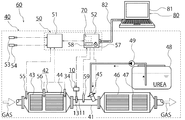
- FIG. 2 illustrates an engine 40 that includes a urea water control unit (hereinafter, “DCU”) 52 as an in-vehicle electronic computer that stores a cleaning program 70 according to an embodiment of the present invention.
- the cleaning program 70 for the NOx sensor 10 is a program that eliminates the influence of disturbance on the oxygen concentration in the reference air chamber 21 of the NOx sensor 10.
- the disturbance can be exemplified by a change in the oxygen concentration in the reference air chamber 21 and the entry of moisture or hydrocarbons into the reference air chamber 21.
- the NOx sensor 10 includes a sensor main body 13 made of an oxygen ion conductive solid electrolyte body 12 such as zirconia (ZrO 2 ) disposed inside a housing 11.
- the sensor body 13 includes a sensor element 14 and a heater 15 disposed adjacent to the sensor element 14.
- an introduction chamber 17, an adjustment chamber 18, and a measurement chamber 19 are disposed in order from the exhaust gas introduction port 16 of the sensor element 14 to the back.
- the measurement chamber 19 is in communication.
- An outside air introduction path 20 for introducing outside air is disposed outside the exhaust passage 41 of the solid electrolyte body 12.
- a reference air chamber 21 communicating with the outside air introduction path 20 is disposed in the solid electrolyte body 12.
- the sensor element 14 includes a first pump cell 22, a first oxygen partial pressure detection cell 23, a second pump cell 24, a second oxygen partial pressure detection cell 25, a measurement pump cell 26, a third oxygen partial pressure detection cell 27, and A reference pump cell 28 is provided.
- the first pump cell 22 includes a first pump electrode 29 disposed inside the adjustment chamber 18, a second pump electrode 30 disposed outside the sensor element 14, and the first pump electrode 29 and the second pump electrode 30.
- the solid electrolyte body 12 is sandwiched.
- the first oxygen partial pressure detection cell 23 includes a first pump electrode 29, a reference electrode 31 disposed inside the reference air chamber 21, and the solid electrolyte body 12 sandwiched between the first pump electrode 29 and the reference electrode 31. It is comprised by.
- the second pump cell 24 includes a second pump electrode 30, a third pump electrode 32 disposed inside the measurement chamber 19, and the solid electrolyte body 12 sandwiched between the second pump electrode 30 and the third pump electrode 32. It is configured.
- the second oxygen partial pressure detection cell 25 includes a reference electrode 31, a third pump electrode 32, and the solid electrolyte body 12 sandwiched between the reference electrode 31 and the third pump electrode 32.
- the measurement pump cell 26 includes a second pump electrode 30, a measurement electrode 33 arranged inside the measurement chamber 19, and the solid electrolyte body 12 sandwiched between the second pump electrode 30 and the measurement electrode 33.
- the third oxygen partial pressure detection cell 27 includes a reference electrode 31, a measurement electrode 33, and the solid electrolyte body 12 sandwiched between the reference electrode 31 and the measurement electrode 33.
- the reference pump cell 28 includes a second pump electrode 30, a reference electrode 31, and the solid electrolyte body 12 sandwiched between the second pump electrode 30 and the reference electrode 31.
- the NOx sensor 10 includes a heater power supply 35 that supplies power to the heater 15, a first power supply 36 a that supplies power to the first pump cell 22, and a second power supply that supplies power to the second pump cell 24.
- a reference power source 38 is provided.
- this NOx sensor 10 when detecting the concentration of nitrogen oxide in the exhaust gas, first, power is supplied to the heater 15 from the heater power source 35, and the sensor element 14 is heated. Thereby, the electrical conductivity of the oxygen ion of the solid electrolyte body 12 is improved by raising the temperature of the sensor element 14 to a predetermined measurement temperature Tmax.
- the switch 37 When the temperature of the sensor element 14 rises to the measured temperature Tmax, the switch 37 is turned on, a predetermined reference pump current I3 is supplied to the reference pump cell 28, and the oxygen concentration of the reference air chamber 21 is set to a predetermined reference oxygen concentration. While maintaining at ⁇ 0, the reference air chamber 21 is cleaned by the reference electrode 31.
- This cell electromotive force V ⁇ b> 3 indicates the partial pressure of oxygen in the reference air chamber 21 and the exhaust passage 41.
- the second power source 36b is controlled based on the electromotive force V1 detected by the second oxygen partial pressure detection cell 25.
- the second pump current I1 in the second pump cell 24 is controlled, and the second pump cell 24 performs the oxygen pumping operation of the measurement chamber 19.
- the oxygen partial pressure in the atmosphere in the measurement chamber 19 is controlled to a low oxygen partial pressure value that does not substantially affect the measurement of NOx.
- the second pump current I1 of the second pump cell 24 is input as a control signal to the first oxygen partial pressure detection cell 23, and the electromotive force V0 is controlled, so that the atmosphere in the measurement chamber 19 is controlled.
- the gradient of the oxygen partial pressure is controlled so as to be always constant.
- the third power source 36c is controlled so that the electromotive force V2 in the third oxygen partial pressure detection cell 27 is constant. Accordingly, the measurement pump cell 26 performs a pumping operation of oxygen in which NOx is reduced or decomposed around the measurement electrode 33 in the measurement chamber 19. Thus, the amount of oxygen generated around the measurement electrode 33 is proportional to the concentration of NOx in the gas to be measured. Therefore, the concentration of NOx in the exhaust gas is calculated by detecting the pump current I2 in the measurement pump cell 26.
- an oxidation catalyst 43 In the post-treatment device 42, an oxidation catalyst 43, a collection device 44, a urea water injection valve 45, an SCR catalyst 46, and an ammonia slip catalyst 47 are arranged in this order from the upstream side of the exhaust passage 41.
- the oxidation catalyst 43 oxidizes unburned hydrocarbons and carbon monoxide in the exhaust gas and oxidizes nitrogen monoxide to generate nitrogen dioxide.
- the collecting device 44 nitric oxide is oxidized by the supported catalyst to generate nitrogen dioxide, and particulate matter in the exhaust gas is collected. Further, in the collection device 44, the particulate matter is oxidized and removed by reacting the collected particulate matter with nitrogen dioxide.
- nitrogen oxides in the exhaust gas whose temperature has increased due to the oxidation reaction between the oxidation catalyst 43 and the collection device 44 are generated by hydrolysis of urea water injected from the urea water injection valve 45. It is reduced by each SCR reaction using ammonia as a reducing agent.
- the urea water injected from the urea water injection valve 45 is stored in the urea water tank 48.
- the urea water stored in the urea water tank 48 is pumped by a pressure pump 49 and transferred to the urea water injection valve 45 via a pipe.
- the engine 40 includes a control unit 50 as a unit of an in-vehicle electronic computer that controls the engine 40.
- the control unit 50 includes an engine control device (hereinafter referred to as ECM) 51 that controls the fuel injection amount and a DCU 52 that controls the injection of urea water in the aftertreatment device 42.
- ECM engine control device
- An ignition-on sensor 53, a vehicle speed sensor 54, an exhaust temperature sensor 55, and a differential pressure sensor 56 are connected to the ECM 51.
- the DCU 52 is provided with a soak timer 57 that acquires the soak time that is the stop time of the vehicle and a counter 58 that counts the number of times the ignition is turned on, and the NOx sensor 10 and the exhaust gas temperature sensor 59 are connected.
- each sensor etc. is an example and is not limited to this structure.
- the engine 40 is mounted on the vehicle 60.
- An inspection device 80 is provided in a service station that inspects and maintains the vehicle 60.
- the inspection device 80 includes an outside electronic computer 81 and a communication device 82 that connects the outside electronic computer 81 and the DCU 52.
- the external electronic computer 81 is connected to the DCU 52 by a communication device 82 and is configured by a computer capable of transmitting / receiving data to / from each other and includes a CPU, a memory, a storage medium, an input device, and an output device.
- Examples of the communication device 82 include an optical cable, a coaxial cable, a TP cable, a serial cable, and a parallel cable.
- the cleaning program 70 is stored in the storage medium of the DCU 52 provided as an in-vehicle electronic computer.
- the cleaning program 70 is configured such that cleaning control is executed when a predetermined cleaning time t1 is reached.
- the cleaning program 70 causes the DCU 52 to execute step S20 as a starting procedure when the cleaning time t1 is reached in step S10.
- the control unit 34 is caused to execute steps S30 to S40 as a cleaning procedure.
- the NOx sensor 10 cleaning method performed by executing the cleaning program 70 causes the current flowing through the reference pump cell 28 to be larger than the reference pump current I3 when the predetermined cleaning time t1 is reached.
- the cleaning pump current I4 set to the current value is used, and the oxygen concentration in the reference air chamber 21 is set to the cleaning oxygen concentration ⁇ 1 set to a concentration higher than the reference oxygen concentration ⁇ 0.
- the reference pump current I3 is lowered to suppress the deterioration of the reference electrode 31. Further, by reducing the reference pump current I3, the heater 15 is prevented from being deteriorated due to the oxygen in the reference air chamber 21 flowing into the heater. This improves the durability of the NOx sensor 10 during normal use.
- the current flowing through the reference pump cell 28 is changed to the cleaning pump current I4 to oxidize and remove hydrocarbons, carbon monoxide, and water on the reference electrode 31, and the reference air chamber 21.
- the oxygen concentration in the purified oxygen concentration ⁇ 1 to discharge oxygen from the reference air chamber 21 to the outside air introduction path 20
- hydrocarbons, carbon monoxide, and water are discharged from the reference air chamber 21.
- the cleaning program 70 the engine 40 including the DCU 52 storing the cleaning program 70, and the cleaning method of the NOx sensor 10, the durability of the NOx sensor 10 is not impaired. Improve robustness and reliability against disturbances.
- the cleaning program 70 is started when the cleaning time t1 is reached.
- the first cleaning time t1 in this embodiment is when the vehicle 60 stops at the service station and the vehicle 60 is inspected by the inspection device 80 provided at the service station. More specifically, during the cleaning time t1, the vehicle 60 stops at the service station, the outside computer 81 of the inspection device 80 is connected to the DCU 52 by the communication device 82, and the inspection command transmitted from the outside computer 81 is sent to the DCU 52. This is when the received step S10 is performed.
- step S10 when the cleaning time t1 is reached in step S10, the DCU 52 is caused to execute step S20 for transmitting a start command for causing the control unit 34 of the NOx sensor 10 to perform cleaning control to the control unit 34.
- step S30 for setting the current flowing through the reference pump cell 28 from the reference pump current I3 to the cleaning pump current I4 is performed.
- the controller 34 is caused to execute.
- step S40 in which the reference power source 38 is controlled to supply the cleaning pump current I4 to the reference pump cell 28.
- the cleaning pump current I4 is derived from the reference pump current I3 based on the partial pressure of oxygen in the reference air chamber 21 and the exhaust passage 41, the volume of the reference air chamber 21 and the size of the reference electrode 31. Is also set to a high value.
- the cleaning pump current I4 has a value that does not reduce the durability of the solid electrolyte body 12 and the reference electrode 31 constituting the sensor element 14 in a short-term use for cleaning, and the reference air chamber.
- the oxygen concentration of 21 is set to a value that makes the purified oxygen concentration ⁇ 1 set to a concentration higher than the reference oxygen concentration ⁇ 0.
- the oxygen partial pressures in the reference air chamber 21 and the exhaust passage 41 can be obtained from the cell electromotive force V3 of the reference pump cell 28 when the switch 37 is turned off. Further, the cleaning pump current I4 becomes larger as the volume of the reference air chamber 21 is larger. For example, the value of the cleaning pump current I4 is 2 to 5 times the value of the reference pump current I3.
- step S40 the DCU 52 is caused to execute step S50 for obtaining the resistance value R of the reference pump cell 28 via the control unit 34.
- step S60 the DCU 52 is caused to execute step S60 for determining whether or not the resistance value R is equal to or greater than a predetermined end determination value Ra.
- step S60 If the resistance value R is smaller than the end determination value Ra in step S60, the process returns to step S30 and the energization of the cleaning pump current I4 is continued. On the other hand, when the resistance value R becomes equal to or greater than the end determination value Ra in step S60, the DCU 52 is caused to execute step S70 for transmitting an end command for stopping the cleaning control to the control unit 34.
- the end determination value Ra is set to a value for determining that the influence of disturbance has been eliminated by the cleaning control in step S40.
- the end determination value Ra is preferably set based on a resistance value R1 at which the electromotive force V3 becomes the oxygen partial pressure of the reference air chamber 21 and the exhaust passage 41 when the reference pump current I3 is supplied to the reference pump cell 28. .
- control unit 34 receives the termination command transmitted in step S70, when the switch 37 is turned on, the current to be passed through the reference pump cell 28 is set from the cleaning pump current I4 to the reference pump current I3.
- the controller 34 is caused to execute.
- control unit 34 is caused to execute step S90 in which the reference power source 38 is controlled and the reference pump current I3 is supplied to the reference pump cell 28, and the program ends.
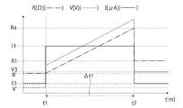
- FIG. 4 shows an example of the relationship between the elapsed time and the resistance value R, voltage value V, and current value I in the reference pump cell 28.
- the time when step S90 is started is assumed to be t2.
- the oxygen concentration in the reference air chamber 21 of the NOx sensor 10 cannot maintain the reference oxygen concentration ⁇ 0 due to disturbance. That is, the voltage value V ′ at this time is smaller than the cell electromotive force V3 based on the partial pressure of oxygen in the reference air chamber 21 and the exhaust passage 41, and the resistance value R ′ is also reduced accordingly.
- the inspection command transmitted from the electronic computer 81 outside the vehicle is received by the DCU 52 and the cleaning time t1 is reached, the cleaning program 70 is started.
- step S40 when step S40 is started, the cleaning pump current I4 flows through the reference pump cell 28. Thereby, the exclusion of the influence of the disturbance is started.
- the applied voltage V increases with the current value I.
- the resistance value R of the reference pump cell 28 also increases.
- step S90 is started at time t2.
- the period ⁇ t1 between the time t1 and the time t2 is a period in which the control unit 34 is performing the cleaning control. This period ⁇ t1 is sufficient on average, but may be several hours depending on the driving state of the vehicle 60.
- the NOx sensor 10 is cleaned until the resistance value R of the reference pump cell 28 when the current flowing through the reference pump cell 28 is set to the cleaning pump current I4 is equal to or higher than the predetermined end determination value Ra.
- the influence of the disturbance is completely eliminated, and the inside of the reference air chamber 21 is cleaned.
- the cleaning control can be ended, so that the time during which the cleaning pump current I4 flows can be shortened, and the durability of the NOx sensor 10 can be reduced. It is advantageous for improvement.
- a period ⁇ t1 may be determined in advance, and step S70 may be executed when the period ⁇ t1 has elapsed.
- a period ⁇ t1 is determined so that the resistance value R of the reference pump cell 28 when the current flowing through experiments and tests is set to the cleaning pump current I4 is equal to or greater than a predetermined end determination value Ra.
- the influence of the disturbance may remain, but the inspection work of the vehicle 60 can be completed quickly.
- the cleaning time t1 is set when the vehicle 60 is inspected as described above, the NOx sensor 10 can be periodically cleaned, so that the NOx sensor 10 can be kept in a good state for a long period of time. It is advantageous to maintain.
- the second cleaning time t1 is set when the traveling distance L1 of the vehicle 60 is equal to or greater than the predetermined cleaning traveling distance La. It is also possible to cause the DCU 52 to execute the time setting procedure.
- the cleaning travel distance La is set to a travel distance that requires the NOx sensor 10 to be cleaned when the vehicle 60 travels in advance through experiments and tests.
- the cleaning travel distance La is set to 5000 km to 30000 km.
- the cleaning program 70 is always executed while the vehicle 60 is traveling.
- the ECM 51 is accessed, and the DCU 52 is caused to execute step S ⁇ b> 100 in which the ECM 51 acquires the travel distance L ⁇ b> 1 of the vehicle 60 acquired from the detection value of the vehicle speed sensor 54.
- step S110 for determining whether or not the acquired travel distance L1 is equal to or greater than the cleaning travel distance La. If the travel distance L1 is shorter than the cleaning travel distance La in step S110, the process returns to step S100. On the other hand, when the travel distance L1 is equal to or greater than the cleaning travel distance La, the time when the determination is performed is set as the cleaning time t1, and step S20 is executed.
- the cleaning time t1 is set when the travel distance L1 becomes equal to or greater than the cleaning travel distance La, the NOx sensor 10 is periodically cleaned based on the travel distance L1 of the vehicle 60. Therefore, it is advantageous to maintain the NOx sensor 10 in a good state.
- the third cleaning time t1 is set at the start of starting the engine 40 after the soak time ⁇ t2 of the vehicle 60 is equal to or longer than a predetermined long-time ⁇ ta. It is also possible to cause the DCU 52 to execute.
- the long-term ⁇ ta is set to a period in which the NOx sensor 10 needs to be cleaned when the vehicle 60 is stopped in advance by experiments or tests.
- the long-term ⁇ ta is set to 7 days to 1 month.
- the cleaning program 70 is executed when the vehicle 60 is started.
- the start time of the vehicle 60 is set when the ignition on sensor 53 detects ignition on.
- the DCU 52 is caused to execute step S ⁇ b> 200 for acquiring the soak time ⁇ t ⁇ b> 2 of the vehicle 60 acquired by the soak timer 57 provided in the DCU 52.
- the soak time is a time during which the target value is kept constant in program control.
- the target value is set to stop the vehicle 60. That is, the soak time ⁇ t2 of the vehicle 60 here is a time after the vehicle is stopped, and is a time from the ignition off to the ignition on.
- step S210 the DCU 52 is caused to execute step S210 for determining whether or not the acquired soak time ⁇ t2 is longer than or equal to ⁇ ta.
- step S210 when the soak time ⁇ t2 is shorter than the long-term ⁇ ta, the cleaning program 70 ends.
- the DCU 52 is caused to execute step S220 for setting the start time of the engine 40 to the cleaning time t1. Then, when the start of the engine 40 is started in step S230, step S20 is executed.
- the cleaning time t1 is set at the start of starting of the engine 40 when the soak time ⁇ t2 is longer than ⁇ ta for a long time, the NOx sensor 10 is cleaned when the vehicle 60 is used after long-term storage.
- the number determination value Na is set to the number of times to determine whether the vehicle 60 is immediately after production. For example, the number determination value Na is set to 100 times.
- the DCU 52 is caused to execute step S ⁇ b> 300 for acquiring the ignition ON frequency Nig acquired by the counter 58 provided in the DCU 52.
- step S310 the DCU 52 is caused to execute step S310 for determining whether or not the obtained ignition on number Nig is less than the number determination value Na.
- step S310 when the ignition ON number Nig is equal to or larger than the number determination value Na, the cleaning program 70 ends.
- step S320 the DCU 52 is caused to execute step S320 for setting the start time of the engine 40 to the cleaning time t1. Then, when the start of the engine 40 is started in step S330, step S20 is executed.
- the NOx sensor 10 By determining whether or not the vehicle 60 is immediately after production based on the number of ignition on times Nig, the influence of moisture and humidity condensed in the reference air chamber 21 during use after long-term storage immediately after production is eliminated, and the NOx sensor 10 is improved. It is advantageous to maintain a stable state.
- step S400 for setting the start time of the engine 40 to the cleaning time t1. Then, when the start of the engine 40 is started in step S410, step S20 is executed.
- the cleaning control period ⁇ t1 performed at the third and fourth cleaning times t1 is set to several tens of minutes, and the cleaning control period ⁇ t1 performed at the fifth cleaning time t1 is several times. Set to minutes.
- the cleaning performed at the third and fourth cleaning times t1 in consideration of the durability of the NOx sensor 10.
- the period is shorter than the control period, it is more advantageous for improving the durability of the NOx sensor 10.
- the DCU 52 it is possible to cause the DCU 52 to execute a time setting procedure for setting the sixth cleaning time t1 to the light-off period ⁇ t3 during which the heater 15 of the NOx sensor 10 is energized.
- FIG. 9 is a graph showing the relationship between the heating time t of the heater 15 and the temperature T of the sensor element 14 at that time when the NOx concentration is detected by the NOx sensor 10.
- the energization start time of the heater 15 is t3
- the time to reach the preheating temperature Tpre is t4
- the time to reach the measurement temperature Tmax is t5
- the end time of the light-off period ⁇ t3 is defined as P1.
- the temperature is raised to the preheating temperature Tpre set to a temperature lower than the measurement temperature Tmax before the temperature rises to the measurement temperature Tmax at which the sensor element 14 is activated.
- the preheating temperature is set to several tens of degrees.
- the light-off period ⁇ t3 is a period from time t4 to time t6, which is a period until each electrode including the reference electrode 31 provided in the sensor element 14 is stabilized.
- the cleaning time t1 is set during the light-off period ⁇ t3, it is preferably between the time t4 at which the light-off period ⁇ t3 starts and the time t5 at which the measured temperature Tmax is reached.
- the cleaning time t1 is provided before the activation of the solid electrolyte body 12, a voltage is applied in a state in which no current flows, so that the durability of the solid electrolyte body 12 may be reduced. Therefore, it is preferable to set the activation point P1 at which the solid electrolyte body 12 is activated near the time t5 as the cleaning time t1.
- the control unit 34 that has received the dew point (dew point) information acquired from the detection value of the exhaust gas temperature sensor 59 from the DCU 52 sets the light-off period ⁇ t3 based on the dew point information. Then, it is executed when energization of the heater 15 is started.
- control unit 34 is accessed, and the DCU 52 is caused to execute step S500 for acquiring the light-off period ⁇ t3 set by the control unit 34.
- step S510 for setting the cleaning time t1 at the activation point P1 of the acquired light-off period ⁇ t3. Then, when the activation point P1 during the light-off period ⁇ t3 is reached in step S520, step S20 is executed.
- the reference air chamber 21 is cleaned early when the oxygen concentration in the reference air chamber 21 is unstable, so that the exhaust gas performance is improved.
- the early activation performance of the extremely important NOx sensor 10 can be improved without impairing durability.
- the cleaning control started during the light-off period ⁇ t3 is performed for a certain period after the temperature of the sensor element 14 rises to the measurement temperature Tmax and the NOx sensor 10 starts detecting the NOx concentration of the exhaust gas. It is desirable that
- the cleaning control period ⁇ t1 in FIG. 9 it is preferable to set the cleaning control period ⁇ t1 in FIG. 9 to a predetermined period.
- the cleaning control period ⁇ t1 performed in the sixth cleaning time t1 is about 10 minutes.
- the DCU 52 it is possible to cause the DCU 52 to execute a time setting procedure for setting the seventh cleaning time t1 to the start time t7 of post-processing control while the vehicle 60 is traveling.
- Post-treatment control refers to regeneration control of the collection device 44 and purge control of the SCR catalyst 46. That is, the start time t7 of the post-processing control is the start time of either the regeneration control of the collection device 44 or the purge control of the SCR catalyst 46.
- the cleaning program 70 is executed when the engine 40 is started.
- the regeneration control start time of the collection device 44 started based on the detection value of the differential pressure sensor 56 connected to the ECM 51, and the detection value of the exhaust temperature sensor 55
- the DCU 52 is caused to execute step S600 for obtaining any start time t7 of the start time of the purge control of the SCR catalyst 46 started based on the above.
- step S610 that sets the cleaning time t1 to the acquired start time t7. Then, when the post-processing control start time t7 is reached in step S620, step S20 is executed.
- the cleaning control performed at the seventh cleaning time t1 it is preferable that the cleaning control is continued for several minutes after the end of the post-processing control.
- this post-processing control can also be applied to rich combustion control of a NOx adsorption reduction catalyst (LNT catalyst) that is not provided in the engine 40 of the embodiment.
- LNT catalyst NOx adsorption reduction catalyst
Landscapes
- Engineering & Computer Science (AREA)
- Chemical & Material Sciences (AREA)
- Combustion & Propulsion (AREA)
- Mechanical Engineering (AREA)
- General Engineering & Computer Science (AREA)
- Health & Medical Sciences (AREA)
- Life Sciences & Earth Sciences (AREA)
- Chemical Kinetics & Catalysis (AREA)
- Molecular Biology (AREA)
- Electrochemistry (AREA)
- Physics & Mathematics (AREA)
- Analytical Chemistry (AREA)
- Biochemistry (AREA)
- General Health & Medical Sciences (AREA)
- General Physics & Mathematics (AREA)
- Immunology (AREA)
- Pathology (AREA)
- Exhaust Gas After Treatment (AREA)
- Combined Controls Of Internal Combustion Engines (AREA)
Abstract
予め定められた清浄化時間t1になった時に、清浄化プログラム70が、清浄化制御を制御部34に行わせる開始指令を制御部34へ発信する開始手順をDCU52に実行させて、その開始指令により、基準ポンプセル28に流れる電流を基準ポンプ電流I3から基準ポンプ電流I3よりも大きい電流値に設定された清浄化ポンプ電流I4にする清浄化制御を行う清浄化手順を制御部34に実行させることで、NOxセンサの耐久性を損なうことなく、外乱に対するロバスト性や信頼性を向上する。
Description
本発明は、NOxセンサの清浄化プログラム及び内燃機関、並びにNOxセンサの清浄化方法に関し、より詳細には、NOxセンサの耐久性を損なうことなく、外乱に対するロバスト性や信頼性を向上するNOxセンサの清浄化プログラム及び内燃機関、並びにNOxセンサの清浄化方法に関する。
ディーゼルエンジンは、排気ガス中のNOx(窒素酸化物)を浄化するために排気通路に配置したNOxセンサで排気ガス中のNOx濃度を検出し、その検出値に基づいて尿素水の噴射量の調節及び、触媒などの自己診断を行っている。
このNOxセンサは、原理上、ジルコニアなどの酸素イオン伝導性の固体電解質層から構成されたセンサ素子に、一定の基準酸素濃度に維持された基準空気室と、その基準空気室に配置された基準電極とを有している。そして、この基準電極とセンサ素子の外側に配置されたポンプ電極とから基準空気室の内部の酸素濃度を基準酸素濃度に維持する基準ポンプセルが構成されている。
このNOxセンサは、外乱などにより、基準空気室の酸素濃度を基準酸素濃度に維持できない場合には、動作不良となって、NOxセンサの測定するNOx濃度が不正になる。なお、ここでいう外乱には、基準空気室の酸素濃度の変化、基準空気室への水分や炭化水素の進入などを例示可能である。
しかし、外乱への耐性の向上のために、基準電極に流れる基準ポンプ電流を増加させると、基準電極の劣化が促進して、NOxセンサの制御不良を生じる。また、基準空気室の酸素がヒータに回り込みヒータの劣化が促進して、センサ素子が十分に加熱されない。
これに関して、例えば日本出願の特開2009-288082号公報(特許文献1)に記載されているように、センサのポンプ電流の増減を制御することが提案されている。この制御では、エンジンの運転状態から算出された排気ガスの成分に基づいてポンプ電流を変化させ、炭化水素などの成分が増加した場合には、ポンプ電流を増加させることで、NOxセンサの信頼性を確保している。
しかし、上記の制御では、車両の長期保管後に基準空気室に水分が凝縮した場合や、NOxセンサのヒータが加熱された場合などには対応しないので、長期的にNOxセンサが良好な状態に維持されない。
また、基準空気室の酸素濃度が基準酸素濃度に維持されていても、排気ガスの成分によっては、基準ポンプ電流が増加することになり、基準電極の劣化やヒータの劣化が進行してしまう。
本発明は、上記の問題を鑑みてなされたものであり、その課題は、NOxセンサの耐久性を損なうことなく、外乱に対するロバスト性や信頼性を向上するNOxセンサの清浄化プログラム及び内燃機関、並びにNOxセンサの清浄化方法を提供することである。
上記の課題を解決するための本発明のNOxセンサの清浄化プログラムは、車両に搭載された内燃機関の排気通路に配置され、センサ素子の内側に外気に連通した基準空気室に配置された基準電極と、該センサ素子の外側に配置された基準ポンプ電極とから該基準空気室の内部への酸素の汲み出しを行う基準ポンプセルが構成され、該基準ポンプセルに流れる電流を予め定められた基準ポンプ電流に調節する制御を行う制御部を備えたNOxセンサの清浄化プログラムにおいて、予め定められた清浄化時間になった時に、清浄化制御を行わせる開始指令を該制御部へ発信する開始手順を前記車両に搭載された車載用電子計算機に実行させ、前記開始指令により、前記基準ポンプセルに流れる電流を前記基準ポンプ電流から該基準ポンプ電流よりも大きい電流値に設定された清浄化ポンプ電流にする前記清浄化制御を行う清浄化手順を前記制御部に実行させることを特徴とするものである。
また、上記の課題を解決するための本発明の内燃機関は、上記に記載のNOxセンサの清浄化プログラムが記録された車載用電子計算機を備えたことを特徴とするものである。
また、上記の課題を解決するための本発明のNOxセンサの清浄化方法は、センサ素子の内側の外気に連通した基準空気室に配置された基準電極と、該センサ素子の外側に配置されたポンプ電極とから構成された基準ポンプセルに流れる電流を予め定めた基準ポンプ電流に調節して、前記基準空気室の酸素濃度を予め定められた基準酸素濃度に維持するNOxセンサの清浄化方法において、予め定めた清浄化時間になった時に、前記基準ポンプセルに流れる電流を、前記基準ポンプ電流よりも大きい電流値に設定された清浄化ポンプ電流にして、前記基準空気室を前記基準酸素濃度よりも大きい濃度に設定された清浄化酸素濃度にすることを特徴とする方法である。
本発明のNOxセンサの清浄化プログラム及び内燃機関、並びにNOxセンサの清浄化方法によれば、予め定めた清浄化時間になったときに、基準ポンプセルに流れる電流を基準ポンプ電流よりも高い清浄化ポンプ電流にすることで、通常使用時には、基準ポンプ電流を低くしてNOxセンサの耐久性を向上すると共に、清浄化ポンプ電流を流すことで、基準ポンプセルと基準空気室とを清浄化し、NOxセンサを良好な状態に維持する。
これにより、NOxセンサの耐久性を損なうことなく、外乱に対するロバスト性や信頼性を向上する。
以下、本発明のNOxセンサの清浄化プログラム及び内燃機関、並びにNOxセンサの清浄化方法について説明する。図1は、NOxセンサ10の構成を例示し、図2は、本発明の実施形態の清浄化プログラム70を記憶した車載用電子計算機として尿素水制御装置(以下、DCU)52を備えたエンジン40の構成を例示している。このNOxセンサ10の清浄化プログラム70は、NOxセンサ10の基準空気室21の酸素濃度を、外乱による影響を排除するプログラムである。なお、この外乱とは、基準空気室21の酸素濃度の変化、基準空気室21への水分や炭化水素の進入などを例示可能である。
図1に示すように、NOxセンサ10は、ハウジング11の内部に、ジルコニア(ZrO2)などの酸素イオン伝導性の固体電解質体12により構成されたセンサ本体13が配置されている。このセンサ本体13は、センサ素子14と、このセンサ素子14に隣接して配置されたヒータ15と、を備えている。
固体電解質体12の排気通路41側には、センサ素子14の排気ガスの導入口16から奥に向って導入室17、調整室18、及び測定室19が順に配置されており、導入口16から測定室19までが連通している。また、固体電解質体12の排気通路41の外側には、外気を導入する外気導入路20が配置されている。加えて、固体電解質体12には、その外気導入路20に連通した基準空気室21が配置されている。
また、センサ素子14には、第一ポンプセル22、第一酸素分圧検出セル23、第二ポンプセル24、第二酸素分圧検出セル25、測定ポンプセル26、第三酸素分圧検出セル27、及び基準ポンプセル28が設けられている。
第一ポンプセル22は、調整室18の内部に配置された第一ポンプ電極29と、センサ素子14の外側に配置された第二ポンプ電極30と、第一ポンプ電極29及び第二ポンプ電極30に挟持された固体電解質体12とにより構成されている。第一酸素分圧検出セル23は、第一ポンプ電極29と、基準空気室21の内部に配置された基準電極31と、第一ポンプ電極29及び基準電極31に挟持された固体電解質体12とにより構成されている。第二ポンプセル24は、第二ポンプ電極30と、測定室19の内部に配置された第三ポンプ電極32と、第二ポンプ電極30及び第三ポンプ電極32に挟持された固体電解質体12とにより構成されている。第二酸素分圧検出セル25は、基準電極31と、第三ポンプ電極32と、基準電極31及び第三ポンプ電極32に挟持された固体電解質体12とにより構成されている。測定ポンプセル26は、第二ポンプ電極30と、測定室19の内部に配置された測定電極33と、第二ポンプ電極30及び測定電極33に挟持された固体電解質体12とにより構成されている。第三酸素分圧検出セル27は、基準電極31と、測定電極33と、基準電極31及び測定電極33に挟持された固体電解質体12とにより構成されている。基準ポンプセル28は、第二ポンプ電極30と、基準電極31と、第二ポンプ電極30及び基準電極31に挟持された固体電解質体12とにより構成されている。
また、このNOxセンサ10は、制御部34の内部に、ヒータ15に電力を供給するヒータ電源35、第一ポンプセル22に電力を供給する第一電源36a、第二ポンプセル24に電力を供給する第二電源36b、測定ポンプセル26に電力を供給する第三電源36c、基準ポンプセル28の基準ポンプ電流I3の通電とセル起電力V3の測定の動作とを切り換えるスイッチ37、及び基準ポンプセル28に電力を供給する基準電源38を備えている。
このNOxセンサ10においては、排気ガス中の窒素酸化物の濃度を検出するに際に、先ず、ヒータ15にヒータ電源35から電力が供給されて、センサ素子14が加熱される。これにより、センサ素子14の温度を予め定められた測定温度Tmaxまで昇温することで、固体電解質体12の酸素イオンの導電性を高めている。
センサ素子14の温度が測定温度Tmaxまで上昇すると、スイッチ37をオンにして、基準ポンプセル28に予め定められた基準ポンプ電流I3を流し、基準空気室21の酸素濃度を予め設定された基準酸素濃度ρ0に維持すると共に、基準電極31での基準空気室21の清浄化が行われている。
次いで、スイッチ37をオフにして、基準ポンプセル28にてセル起電力V3が検出される。このセル起電力V3は、基準空気室21と排気通路41との酸素分圧を示している。
次いで、第二酸素分圧検出セル25にて検出される起電力V1に基づいて、第二電源36bが制御される。これに伴って、第二ポンプセル24における第二ポンプ電流I1が制御されて、第二ポンプセル24が測定室19の酸素のポンピング作動を行う。これにより、測定室19内の雰囲気中の酸素分圧を、NOxの測定に実質的に影響がない低い酸素分圧値に制御するようになっている。
また、この第二ポンプセル24の第二ポンプ電流I1は、制御信号として、第一酸素分圧検出セル23に入力され、その起電力V0が制御されることにより、測定室19内の雰囲気中の酸素分圧の勾配が、常に一定となるように制御されている。
次いで、第三酸素分圧検出セル27における起電力V2が一定となるように第三電源36cが制御される。これに伴って、測定ポンプセル26が測定室19内の測定電極33の周りでNOxが還元又は分解された酸素のポンピング作動を行う。このように測定電極33の周りにおいて発生する酸素の量は、被測定ガス中のNOxの濃度に比例する。従って、測定ポンプセル26におけるポンプ電流I2を検出することで、排気ガス中のNOxの濃度が算出される。
次に、上記のNOxセンサ10を排気通路41に配置したエンジン40について説明する。このエンジン40においては、図示しない筒内から排出された排気ガスが、排気通路41に配置された後処理装置42により浄化されて大気へと放出されている。
後処理装置42には、排気通路41の上流側から順に、酸化触媒43、捕集装置44、尿素水噴射弁45、SCR触媒46、及びアンモニアスリップ触媒47が配置されている。排気ガスがこの後処理装置42を通過すると、酸化触媒43では、排気ガス中の未燃炭化水素と一酸化炭素とが酸化されると共に、一酸化窒素が酸化されて二酸化窒素が生成される。次いで、捕集装置44では、担持された触媒によって一酸化窒素が酸化されて二酸化窒素が生成されると共に、排気ガス中の微粒子状物質が捕集される。また、この捕集装置44では、捕集した微粒子状物質と二酸化窒素とを反応させることで微粒子状物質が酸化除去される。次いで、SCR触媒46では、酸化触媒43と捕集装置44との酸化反応で温度が上昇した排気ガス中の窒素酸化物が、尿素水噴射弁45から噴射された尿素水の加水分解により生じたアンモニアを還元剤とした各SCR反応によって還元される。
尿素水噴射弁45から噴射される尿素水は尿素水タンク48に貯蔵されている。その尿素水タンク48に貯蔵された尿素水は、圧送ポンプ49により圧送され、配管を経由して尿素水噴射弁45へ移送されている。
また、このエンジン40においては、エンジン40を制御する車載用電子計算機のユニットとして制御ユニット50を備えている。この制御ユニット50は、燃料の噴射量を制御するエンジン制御装置(以下、ECM)51や後処理装置42における尿素水の噴射を制御するDCU52を有している。このECM51にはイグニッションオンセンサ53、車速センサ54、排気温度センサ55、及び差圧センサ56が接続されている。また、DCU52には、車両の停止時間であるソーク時間を取得するソークタイマ57とイグニッションオン回数をカウントするカウンタ58とが設けられており、NOxセンサ10及び排気ガス温度センサ59が接続されている。なお、各センサなどは一例であり、この構成に限定されない。
そして、このエンジン40は、車両60に搭載されている。また、この車両60の点検や整備を行うサービスステーションには、点検装置80が備えられている。この点検装置80は、車外電子計算機81と、車外電子計算機81及びDCU52を接続する通信機82とを有している。
車外電子計算機81は通信機82によりDCU52に接続されて、相互にデータを送受信可能なコンピュータで構成され、CPU、メモリ、記憶媒体、入力装置、及び出力装置を有している。通信機82としては、光ケーブル、同軸ケーブル、TPケーブル、シリアルケーブル、及びパラレルケーブルなどを例示可能である。
このようなエンジン40においては、車載電子計算機として備えられたDCU52の記憶媒体に清浄化プログラム70が記憶されている。この清浄化プログラム70は、予め定められた清浄化時間t1になったときに清浄化制御が実行されように構成されている。
図3に示すように、この清浄化プログラム70は、ステップS10で清浄化時間t1になった時に、開始手順としてステップS20をDCU52に実行させる。次いで、清浄化手順としてステップS30~ステップS40を制御部34に実行させる。
つまり、清浄化プログラム70を実行することで行われるNOxセンサ10の清浄化方法は、予め定められた清浄化時間t1になった時に、基準ポンプセル28に流れる電流を、基準ポンプ電流I3よりも大きい電流値に設定された清浄化ポンプ電流I4にして、基準空気室21の酸素濃度を基準酸素濃度ρ0よりも大きい濃度に設定された清浄化酸素濃度ρ1にする方法である。
つまり、通常使用時には、基準ポンプ電流I3を低くして基準電極31の劣化を抑制する。また、基準ポンプ電流I3を低くすることで、基準空気室21の酸素がヒータに回り込むことによるヒータ15の劣化を防止する。これにより、通常使用時のNOxセンサ10の耐久性を向上する。
一方、清浄化時間t1になった時には、基準ポンプセル28に流れる電流を清浄化ポンプ電流I4にして、基準電極31上で炭化水素、一酸化炭素、及び水を酸化除去すると共に、基準空気室21の酸素濃度を清浄化酸素濃度ρ1にすることで、基準空気室21から酸素を外気導入路20に排出することで、炭化水素、一酸化炭素、及び水を基準空気室21から排出する。これにより、外乱の影響を排除して基準空気室21を清浄化し、NOxセンサ10を良好な状態に維持する。
以上のことから、上記の清浄化プログラム70、及びその清浄化プログラム70を記憶したDCU52を備えたエンジン40、並びにNOxセンサ10の清浄化方法によれば、NOxセンサ10の耐久性を損なうことなく、外乱に対するロバスト性や信頼性を向上する。
次に、この清浄化プログラム70についての詳細を説明する。
この清浄化プログラム70は、清浄化時間t1になったときに開始される。この実施形態の第一の清浄化時間t1は、車両60がサービスステーションに停車し、サービスステーションに設けられた点検装置80による車両60の点検時である。詳しく説明すると、清浄化時間t1は、車両60がサービスステーションに停車し、点検装置80の車外電子計算機81が通信機82によってDCU52に接続され、車外電子計算機81から発信された点検指令がDCU52に受信されたステップS10が行われた時である。
次いで、ステップS10で清浄化時間t1になると、NOxセンサ10の制御部34に清浄化制御を行わせる開始指令を制御部34へ発信するステップS20をDCU52に実行させる。
次いで、ステップS20で発信された開始指令を制御部34が受信すると、スイッチ37をオンにしたときに、基準ポンプセル28に流す電流を基準ポンプ電流I3から清浄化ポンプ電流I4に設定するステップS30を制御部34に実行させる。次いで、基準電源38を制御させてその清浄化ポンプ電流I4を基準ポンプセル28に通電するステップS40を制御部34に実行させる。
図4に示すように、清浄化ポンプ電流I4は、基準空気室21及び排気通路41の酸素分圧と、その基準空気室21の容積及び基準電極31の大きさとに基づいて基準ポンプ電流I3よりも高い値に設定されている。この清浄化ポンプ電流I4は、清浄化の為の短期間の使用においてはセンサ素子14を構成する固体電解質体12や基準電極31の耐久性を低下させることの無い値で、且つ、基準空気室21の酸素濃度を基準酸素濃度ρ0よりも大きい濃度に設定された清浄化酸素濃度ρ1にする値に設定されている。基準空気室21及び排気通路41の酸素分圧は、スイッチ37をオフにしたときの基準ポンプセル28のセル起電力V3から取得可能である。また、この清浄化ポンプ電流I4は基準空気室21の容積が大きいほど大きい値となる。例えば、清浄化ポンプ電流I4の値は基準ポンプ電流I3の値の2倍~5倍である。
なお、基準ポンプセル28に流れる電流値を基準ポンプ電流I3から清浄化ポンプ電流I4にした際に、基準空気室21及び排気通路41の酸素分圧が変化する。この酸素分圧の変化によりセル起電力V3も変化するが、そのセル起電力V3の変化に伴って、第二酸素分圧検出セル25、及び第三酸素分圧セル27のそれぞれの酸素分圧(各起電力V1、V2)が変化しないように、各セル22~27における電流と電圧を変化させることが望ましい。
次いで、ステップS40を制御部34に実行させている最中に、制御部34を経由して基準ポンプセル28の抵抗値Rを取得するステップS50をDCU52に実行させる。次いで、抵抗値Rが予め定められた終了判定値Ra以上になるか否かを判定するステップS60をDCU52に実行させる。
ステップS60で抵抗値Rが終了判定値Raよりも小さい場合には、ステップS30へ戻り、清浄化ポンプ電流I4の通電を続ける。一方、ステップS60で抵抗値Rが終了判定値Ra以上になった場合には、清浄化制御を停止させる終了指令を制御部34へ発信するステップS70をDCU52に実行させる。
終了判定値Raは、ステップS40における清浄化制御によって外乱による影響が排除されたことを判定する値に設定される。この終了判定値Raは基準ポンプセル28に基準ポンプ電流I3を流した場合に、起電力V3が基準空気室21及び排気通路41の酸素分圧となる抵抗値R1に基づいて設定されることが好ましい。
次いで、ステップS70で発信された終了指令を制御部34が受信すると、スイッチ37をオンにしたときに、基準ポンプセル28に流す電流を清浄化ポンプ電流I4から基準ポンプ電流I3に設定するステップS80を制御部34に実行させる。次いで、基準電源38を制御させてその基準ポンプ電流I3を基準ポンプセル28に通電するステップS90を制御部34に実行させて、このプログラムは終了する。
図4は、経過時間と基準ポンプセル28における抵抗値R、電圧値V、及び電流値Iとの関係の一例を示している。ここで、ステップS90が開始された時間をt2とする。
サービスステーションに到着時には外乱によってNOxセンサ10の基準空気室21の酸素濃度は基準酸素濃度ρ0を維持できていない状態である。つまり、このときの電圧値V’は基準空気室21及び排気通路41の酸素分圧に基づいたセル起電力V3よりも小さくなり、それに伴って抵抗値R’も小さくなっている。車外電子計算機81から発信された点検指令がDCU52に受信されて、清浄化時間t1になると清浄化プログラム70が開始される。
次いで、ステップS40が開始されると基準ポンプセル28には清浄化ポンプ電流I4が流れる。これにより、外乱の影響の排除が開始される。印加電圧Vは電流値Iに応じ増加する。一方で、外乱の影響の排除が進むに連れて酸素分圧に応じた起電力が生じる為に、その印加電圧Vは、さらに上昇していく。そのため、基準ポンプセル28の抵抗値Rも上昇していく。
次いで、抵抗値Rが終了判定値Ra以上となると、時間t2でステップS90が開始される。
この時間t1と時間t2との間の期間Δt1が制御部34に清浄化制御を実行させている期間となる。この期間Δt1は平均的には十分程度であるが、車両60の運転状態によっては数時間となることもある。
このように、基準ポンプセル28に流れる電流を清浄化ポンプ電流I4にした際の基準ポンプセル28の抵抗値Rが予め定められた終了判定値Ra以上になるまで、NOxセンサ10の清浄化を行うことで、外乱による影響を完全に排除して、基準空気室21の内部を清浄化する。
また、基準ポンプセル28の抵抗値Rが終了判定値Ra以上になったときに、清浄化制御を終了できるので、清浄化ポンプ電流I4が流れる時間を短縮可能になり、NOxセンサ10の耐久性の向上には有利となる。
なお、ステップS60の判定手順に代えて、期間Δt1を予め定めておき、その期間Δt1が経過したときにステップS70を実行させるようにしてもよい。この場合には、予め実験や試験により流れる電流を清浄化ポンプ電流I4にした際の基準ポンプセル28の抵抗値Rが予め定められた終了判定値Ra以上になるような期間Δt1を求めておく。このようにステップS60の代わりに求めた期間Δt1を用いると、外乱による影響が残る場合があるが、車両60の点検作業を早く完了させられる。
また、上記のように、車両60の点検時に清浄化時間t1が設定されることで、定期的にNOxセンサ10を清浄化可能になるので、長期間に渡ってNOxセンサ10を良好な状態に維持するには有利となる。
また、上記の清浄化プログラム70においては、車両60の走行中には、第二の清浄化時間t1を車両60の走行距離L1が予め定められた清浄化走行距離La以上になった時に設定する時間設定手順をDCU52に実行させることも可能になる。
清浄化走行距離Laは、予め実験や試験により車両60を走行させた場合に、NOxセンサ10の清浄化が必要になる走行距離に設定されている。例えば、この清浄化走行距離Laは、5000km~30000kmに設定される。
この場合には、清浄化プログラム70は、車両60の走行中に常に実行している。
図5に示すように、時間設定手順においては、ECM51にアクセスして、ECM51が車速センサ54の検出値から取得していた車両60の走行距離L1を取得するステップS100をDCU52に実行させる。
次いで、取得した走行距離L1が清浄化走行距離La以上か否かを判定するステップS110をDCU52に実行させる。このステップS110で、走行距離L1が清浄化走行距離Laより短い場合には、ステップS100へ戻る。一方、走行距離L1が清浄化走行距離La以上の場合には、その判定を行った時を清浄化時間t1として、ステップS20を実行させる。
走行距離L1が清浄化走行距離La以上になった時に清浄化時間t1が設定されることで、車両60の走行距離L1に基づいて定期的にNOxセンサ10を清浄化するので、長期間に渡ってNOxセンサ10を良好な状態に維持するには有利となる。
また、上記の清浄化プログラム70においては、第三の清浄化時間t1を車両60のソーク時間Δt2が予め定められた長期間Δta以上になった後のエンジン40の始動開始時に設定する時間設定手順をDCU52に実行させることも可能である。
長期間Δtaは、予め実験や試験により車両60を停止した場合に、NOxセンサ10の清浄化が必要になる期間に設定されている。例えば、この長期間Δtaは、7日~1ヶ月に設定される。
この場合には、清浄化プログラム70は、車両60の始動時に実行される。この車両60の始動時は、イグニッションオンセンサ53でイグニッションオンを検出したときに設定されている。
図6に示すように、DCU52に設けられたソークタイマ57の取得していた車両60のソーク時間Δt2を取得するステップS200をDCU52に実行させる。なお、ソーク時間とはプログラム制御においては目標値を一定にしている時間のことである。このステップS200では目標値を車両60の停車としている。つまり、ここでいう車両60のソーク時間Δt2とは、車両が停止されてからの時間のことであり、イグニッションオフからイグニッションオンまでの時間のことである。
次いで、取得したソーク時間Δt2が長期間Δta以上か否かを判定するステップS210をDCU52に実行させる。このステップS210で、ソーク時間Δt2が長期間Δtaより短い場合には、清浄化プログラム70は終了する。一方、ソーク時間Δt2が長期間Δta以上の場合には、エンジン40の始動開始時を清浄化時間t1に設定するステップS220をDCU52に実行させる。そして、ステップS230でエンジン40の始動が開始されるとステップS20を実行させる。
ソーク時間Δt2が長期間Δta以上になった場合のエンジン40の始動開始時に清浄化時間t1が設定されることで、車両60の長期保管後の使用時にNOxセンサ10を清浄化するので、保管中に基準空気室21に凝縮した水分や湿度の影響を排除して、NOxセンサ10を良好な状態に維持するには有利となる。
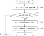
また、上記の清浄化プログラム70においては、第四の清浄化時間t1を車両60のイグニッションオン回数Nigが生産直後を示すように定められた回数判定値Na未満であると判定された後のエンジン40の始動開始時に設定する時間設定手順をDCU52に実行させることも可能である。
回数判定値Naは、車両60が生産直後か否かを判定する回数に設定されている。例えば、この回数判定値Naは、100回に設定される。
図7に示すように、DCU52に設けられたカウンタ58の取得していたイグニッションオン回数Nigを取得するステップS300をDCU52に実行させる。
次いで、取得したイグニッションオン回数Nigが回数判定値Na未満か否かを判定するステップS310をDCU52に実行させる。このステップS310で、イグニッションオン回数Nigが回数判定値Na以上の場合には、清浄化プログラム70は終了する。一方、イグニッションオン回数Nigが回数判定値Na未満の場合には、エンジン40の始動開始時を清浄化時間t1に設定するステップS320をDCU52に実行させる。そして、ステップS330でエンジン40の始動が開始されるとステップS20を実行させる。
イグニッションオン回数Nigにより車両60の生産直後か否かを判定することで、生産直後の長期保管後の使用時に基準空気室21に凝縮した水分や湿度の影響を排除して、NOxセンサ10を良好な状態に維持するには有利となる。
また、上記の清浄化プログラム70においては、第五の清浄化時間t1をエンジン40の始動開始時ごとに設定する時間設定手順をDCU52に実行させることも可能である。
図8に示すように、イグニッションオンセンサ53でイグニッションオンを検出したときに、エンジン40の始動開始時を清浄化時間t1に設定するステップS400をDCU52に実行させる。そして、ステップS410でエンジン40の始動が開始されるとステップS20を実行させる。
このように、エンジン40の始動開始時にNOxセンサ10の清浄化を毎回実施することで、長期間に渡ってNOxセンサ10を良好な状態に維持するには有利となる。
なお、第三~第五の清浄化時間t1においては、第三及び第四の清浄化時間t1で実施される清浄化制御の期間Δt1と、第五の清浄化時間t1で実施される清浄化制御の期間Δt1とを異なる期間に設定することが好ましい。例えば、第三及び第四の清浄化時間t1で実施される清浄化制御の期間Δt1を数十分間に設定し、第五の清浄化時間t1で実施される清浄化制御の期間Δt1を数分間に設定する。特に、第五の清浄化時間t1で実施される清浄化制御はその回数も多くなるため、NOxセンサ10の耐久性を考慮して第三及び第四の清浄化時間t1で実施される清浄化制御の期間よりも短い期間とすると、よりNOxセンサ10の耐久性の向上には有利となる。
また、上記の清浄化プログラム70においては、第六の清浄化時間t1をNOxセンサ10のヒータ15に通電中のライトオフ期間Δt3に設定する時間設定手順をDCU52に実行させることも可能である。
図9は、NOxセンサ10でNOx濃度を検出する際の、ヒータ15の加熱時間tとそのときのセンサ素子14の温度Tとの関係を示したグラフである。ここで、ヒータ15の通電開始時間をt3、予熱温度Tpreになる時間をt4、測定温度Tmaxになる時間をt5、ライトオフ期間Δt3の終了時間で、且つNOxセンサ10でNOx値を出力可能になった時間をt6、固体電解質体12が活性化したとみなせる活性化ポイントをP1とする。
ヒータ15によりセンサ素子14を加熱する際には、センサ素子14が活性化する測定温度Tmaxに昇温する前に、測定温度Tmaxよりも低い温度に設定された予熱温度Tpreに昇温している。このように、測定温度Tmaxに昇温する前に、予熱温度Tpreに昇温することで、センサ素子14の内部に入った、又は付着した水分を蒸発させている。例えば、この予熱温度は、数十度に設定されている。
ライトオフ期間Δt3とは、時間t4から時間t6までの期間であり、センサ素子14に設けられた基準電極31を含む各電極が安定するまでの期間のことをいう。清浄化時間t1をこのライトオフ期間Δt3の期間中に設定する場合には、ライトオフ期間Δt3が開始される時間t4と測定温度Tmaxに到達する時間t5の間が好ましい。特に、固体電解質体12の活性前に清浄化時間t1を設けると電流が流れない状態で電圧印加されるため固体電解質体12の耐久性を低下させる恐れがある。そのため、時間t5の近傍で固体電解質体12が活性化したとみなせる活性化ポイントP1を清浄化時間t1に設定することが好ましい。
この場合には、清浄化プログラム70は、DCU52から排気ガス温度センサ59の検出値から取得した露点(デュウポイント)情報を受信した制御部34が、その露点情報に基づいてライトオフ期間Δt3を設定して、ヒータ15の通電が開始されると実行される。
図10に示すように、制御部34へアクセスして、制御部34で設定されたライトオフ期間Δt3を取得するステップS500をDCU52に実行させる。
次いで、取得したライトオフ期間Δt3の活性化ポイントP1に清浄化時間t1を設定するステップS510をDCU52に実行させる。そして、ステップS520でライトオフ期間Δt3の期間中の活性化ポイントP1になった時に、ステップS20を実行させる。
ライトオフ期間Δt3の期間中に清浄化時間t1が設定されることで、基準空気室21の酸素濃度が不安定なときに、基準空気室21を早期に清浄化するので、排気ガス性能改善に極めて重要なNOxセンサ10の早期活性化性能を、耐久性を損なうことなく向上できる。
このライトオフ期間Δt3の期間中に開始された清浄化制御は、センサ素子14の温度が測定温度Tmaxまで上昇し、NOxセンサ10により排気ガスのNOx濃度の検出が開始された後も一定期間行われることが望ましい。
図9における清浄化制御の期間Δt1を予め定められた期間とすることが好ましい。例えば、この第六の清浄化時間t1で実施される清浄化制御の期間Δt1は、10分程度である。
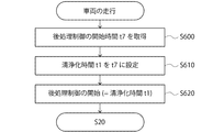
また、上記の清浄化プログラム70においては、第七の清浄化時間t1を車両60の走行中の後処理制御の開始時間t7に設定する時間設定手順をDCU52に実行させることも可能である。
後処理制御とは、捕集装置44の再生制御及びSCR触媒46のパージ制御のことである。つまり、後処理制御の開始時間t7とは、捕集装置44の再生制御及びSCR触媒46のパージ制御のいずれかの開始時間のことである。
この場合には、清浄化プログラム70は、エンジン40の始動時に実行される。
図11に示すように、ECM51へアクセスして、ECM51に接続された差圧センサ56の検出値に基づいて開始される捕集装置44の再生制御の開始時間、及び排気温度センサ55の検出値に基づいて開始されるSCR触媒46のパージ制御の開始時間のいずれかの開始時間t7を取得するステップS600をDCU52に実行させる。
次いで、清浄化時間t1を取得した開始時間t7に設定するステップS610をDCU52に実行させる。そして、そのステップS620で後処理制御の開始時間t7になった時に、ステップS20を実行させる。
後処理制御の開始時間t7に清浄化時間t1が設定されることで、後処理制御によって増加する炭化水素が基準空気室21に回り込んでも、その炭化水素を基準電極31で酸化して、基準空気室21を清浄化するので、後処理制御による外乱の影響を排除して、NOxセンサ10を良好な状態に維持するには有利となる。
なお、この第七の清浄化時間t1で実施される清浄化制御においては、後処理制御の終了後から数分後まで継続されることが好ましい。
なお、この後処理制御には、実施形態のエンジン40には設けられていないNOx吸着還元触媒(LNT触媒)のリッチ燃焼制御にも適用可能である。
10 NOxセンサ
14 センサ素子
15 ヒータ
21 基準空気室
28 基準ポンプセル
30 第二ポンプ電極
31 基準電極
34 制御部
37 スイッチ
38 基準電源
40 エンジン
41 排気通路
42 後処理装置
50 制御ユニット
51 ECM
52 DCU
60 車両
70 清浄化プログラム
I3 基準ポンプ電流
I4 清浄化ポンプ電流
t1 清浄化時間
ρ0 基準酸素濃度
ρ1 清浄化酸素濃度
14 センサ素子
15 ヒータ
21 基準空気室
28 基準ポンプセル
30 第二ポンプ電極
31 基準電極
34 制御部
37 スイッチ
38 基準電源
40 エンジン
41 排気通路
42 後処理装置
50 制御ユニット
51 ECM
52 DCU
60 車両
70 清浄化プログラム
I3 基準ポンプ電流
I4 清浄化ポンプ電流
t1 清浄化時間
ρ0 基準酸素濃度
ρ1 清浄化酸素濃度
Claims (12)
- 車両に搭載された内燃機関の排気通路に配置され、センサ素子の内側に外気に連通した基準空気室に配置された基準電極と、該センサ素子の外側に配置された基準ポンプ電極とから該基準空気室の内部への酸素の汲み出しを行う基準ポンプセルが構成され、該基準ポンプセルに流れる電流を予め定められた基準ポンプ電流に調節する制御を行う制御部を備えたNOxセンサの清浄化プログラムにおいて、
予め定められた清浄化時間になった時に、清浄化制御を行わせる開始指令を該制御部へ発信する開始手順を前記車両に搭載された車載用電子計算機に実行させ、
前記開始指令により、前記基準ポンプセルに流れる電流を前記基準ポンプ電流から該基準ポンプ電流よりも大きい電流値に設定された清浄化ポンプ電流にする前記清浄化制御を行う清浄化手順を前記制御部に実行させることを特徴とするNOxセンサの清浄化プログラム。 - 前記基準ポンプ電流の値を、前記基準空気室の酸素濃度を予め定められた基準酸素濃度に維持する値に設定すると共に、
前記清浄化ポンプ電流の値を、前記基準空気室の酸素濃度を前記基準酸素濃度よりも大きい濃度に設定された清浄化酸素濃度にする値に設定した請求項1に記載のNOxセンサの清浄化プログラム。 - 前記清浄化手順を前記制御部に実行させている最中には、
前記制御部を経由して前記基準ポンプセルにおける抵抗値を取得する抵抗値取得手順と、
取得した前記抵抗値が予め定めた終了判定値以上になるか否かを判定する判定手順と、
前記抵抗値が前記終了判定値以上になったときに、前記制御部に前記清浄化制御を停止する制御を行わせる終了指令を前記制御部へ発信する終了手順と、を前記車載用電子計算機に実行させ、
前記終了指令により、前記清浄化制御を停止する停止手順を前記制御部に実行させる請求項1又は2に記載のNOxセンサの清浄化プログラム。 - 前記車両の点検時には、前記車載用電子計算機に接続された車外電子計算機からの点検指令を該車載用電子計算機が受信した時を前記清浄化時間に設定する時間設定手順を、該車載用電子計算機に実行させる請求項1~3のいずれか1項に記載のNOxセンサの清浄化プログラム。
- 前記車両の走行中には、前記車両に搭載された該車両の走行距離を取得する走行距離取得手段から該走行距離を取得する走行距離取得手順と、取得した該走行距離が前記清浄化走行距離以上か否かを判定する走行距離判定手順と、該走行距離が該清浄化走行距離以上になった時を前記清浄化時間に設定する時間設定手順とを前記車載用電子計算機に実行させる請求項1~4のいずれか1項に記載のNOxセンサの清浄化プログラム。
- 前記車両の始動時には、該車両に搭載された該車両のソーク時間を取得するソーク時間取得手段から該ソーク時間を取得するソーク時間取得手順と、取得した該ソーク時間が予め定められた長期間以上か否かを判定するソーク時間判定手順と、該ソーク時間が該長期間以上になったと判定した場合の前記内燃機関の始動時を前記清浄化時間に設定する時間設定手順とを前記車載用電子計算機に実行させる請求項1~5のいずれか1項に記載のNOxセンサの清浄化プログラム。
- 前記車両の始動時には、該車両に搭載された高電圧回路への通電回数を取得する通電回数取得手段から該通電回数を取得する通電回数取得手順と、取得した該通電回数が予め定められた回数判定値未満か否かを判定する通電回数判定手順と、該通電回数が該回数判定値未満であると判定した場合の前記内燃機関の始動時を前記清浄化時間に設定する時間設定手順とを前記車載用電子計算機に実行させる請求項1~6のいずれか1項に記載のNOxセンサの清浄化プログラム。
- 前記内燃機関の始動時を前記清浄化時間に設定する時間設定手順を前記車載用電子計算機に実行させる請求項1~7のいずれか1項に記載のNOxセンサの清浄化プログラム。
- 前記NOxセンサが前記センサ素子を加熱する電熱式のヒータを有し、
前記ヒータによる前記センサ素子の加熱が開始されたときには、前記制御部が前記ヒータに通電して前記センサ素子を予め定めた測定温度まで昇温する制御を行うライトオフ期間を取得するライトオフ期間取得手順と、取得した該ライトオフ期間中に前記清浄化時間を設定する時間設定手順とを前記車載用電子計算機に実行させる請求項1~8のいずれか1項に記載のNOxセンサの清浄化プログラム。 - 前記車両の走行中には、前記排気通路に配置された捕集装置の再生制御、選択的還元触媒のパージ制御、及びNOx吸着還元触媒のリッチ燃焼制御のいずれかの後処理制御の開始時間を取得する後処理時間取得手順と、取得した該開始時間を前記清浄化時間に設定する時間設定手順とを前記車載用電子計算機に実行させる請求項1~9のいずれか1項に記載のNOxセンサの清浄化プログラム。
- 請求項1~10のいずれか1項に記載のNOxセンサの清浄化プログラムが記録された車載用電子計算機を備えたことを特徴とする内燃機関。
- センサ素子の内側の外気に連通した基準空気室に配置された基準電極と、該センサ素子の外側に配置されたポンプ電極とから構成された基準ポンプセルに流れる電流を予め定めた基準ポンプ電流に調節して、前記基準空気室の酸素濃度を予め定められた基準酸素濃度に維持するNOxセンサの清浄化方法において、
予め定めた清浄化時間になった時に、前記基準ポンプセルに流れる電流を、前記基準ポンプ電流よりも大きい電流値に設定された清浄化ポンプ電流にして、前記基準空気室の酸素濃度を前記基準酸素濃度よりも大きい濃度に設定された清浄化酸素濃度にすることを特徴とするNOxセンサの清浄化方法。
Priority Applications (3)
| Application Number | Priority Date | Filing Date | Title |
|---|---|---|---|
| CN201580064365.3A CN107002588B (zh) | 2014-11-27 | 2015-11-06 | 非易失性计算机可读介质和内燃机、以及NOx传感器的清洁化方法 |
| US15/531,396 US10774707B2 (en) | 2014-11-27 | 2015-11-06 | NOx sensor purification program, internal combustion engine, and NOx sensor purification method |
| EP15863879.1A EP3225826B1 (en) | 2014-11-27 | 2015-11-06 | Nox sensor purification program, internal combustion engine, and nox sensor purification method |
Applications Claiming Priority (2)
| Application Number | Priority Date | Filing Date | Title |
|---|---|---|---|
| JP2014240493A JP2016102699A (ja) | 2014-11-27 | 2014-11-27 | NOxセンサの清浄化プログラム及び内燃機関、並びにNOxセンサの清浄化方法 |
| JP2014-240493 | 2014-11-27 |
Publications (1)
| Publication Number | Publication Date |
|---|---|
| WO2016084584A1 true WO2016084584A1 (ja) | 2016-06-02 |
Family
ID=56074154
Family Applications (1)
| Application Number | Title | Priority Date | Filing Date |
|---|---|---|---|
| PCT/JP2015/081326 WO2016084584A1 (ja) | 2014-11-27 | 2015-11-06 | NOxセンサの清浄化プログラム及び内燃機関、並びにNOxセンサの清浄化方法 |
Country Status (5)
| Country | Link |
|---|---|
| US (1) | US10774707B2 (ja) |
| EP (1) | EP3225826B1 (ja) |
| JP (1) | JP2016102699A (ja) |
| CN (1) | CN107002588B (ja) |
| WO (1) | WO2016084584A1 (ja) |
Cited By (1)
| Publication number | Priority date | Publication date | Assignee | Title |
|---|---|---|---|---|
| WO2022210346A1 (ja) * | 2021-03-31 | 2022-10-06 | 日本碍子株式会社 | センサ素子及びガスセンサ |
Families Citing this family (2)
| Publication number | Priority date | Publication date | Assignee | Title |
|---|---|---|---|---|
| JP7006366B2 (ja) * | 2018-02-23 | 2022-01-24 | いすゞ自動車株式会社 | 窒素酸化物センサ用ヒータ制御装置 |
| JP7314734B2 (ja) * | 2019-09-17 | 2023-07-26 | 株式会社デンソーウェーブ | 流体加熱装置 |
Citations (5)
| Publication number | Priority date | Publication date | Assignee | Title |
|---|---|---|---|---|
| JP2000180400A (ja) * | 1998-12-15 | 2000-06-30 | Toyota Motor Corp | 酸素濃度検出装置 |
| JP2009074884A (ja) * | 2007-09-20 | 2009-04-09 | Toyota Motor Corp | 排気ガスセンサの素子温度制御装置 |
| JP2010237044A (ja) * | 2009-03-31 | 2010-10-21 | Ngk Insulators Ltd | ガスセンサの製造方法、ガスセンサ、およびガスセンサに備わる積層構造 |
| US20140202135A1 (en) * | 2013-01-18 | 2014-07-24 | Ford Global Technologies, Llc | Methods and systems for humidity detection via an exhaust gas sensor |
| JP2015200643A (ja) * | 2014-03-31 | 2015-11-12 | 日本碍子株式会社 | ガスセンサ |
Family Cites Families (4)
| Publication number | Priority date | Publication date | Assignee | Title |
|---|---|---|---|---|
| DE4333231A1 (de) * | 1993-09-30 | 1995-04-06 | Bosch Gmbh Robert | Verfahren zum Betrieb einer Sauerstoffsonde mit interner Referenzatmosphäre |
| JP4983726B2 (ja) | 2008-05-29 | 2012-07-25 | トヨタ自動車株式会社 | ガス濃度センサの暖機制御装置 |
| US8940144B2 (en) * | 2008-07-10 | 2015-01-27 | Robert Bosch Gmbh | Sensor element and method for determining gas components in gas mixtures, and use thereof |
| JP5367044B2 (ja) * | 2011-10-13 | 2013-12-11 | 株式会社日本自動車部品総合研究所 | ガスセンサ素子および内燃機関用ガスセンサ |
-
2014
- 2014-11-27 JP JP2014240493A patent/JP2016102699A/ja active Pending
-
2015
- 2015-11-06 CN CN201580064365.3A patent/CN107002588B/zh active Active
- 2015-11-06 US US15/531,396 patent/US10774707B2/en active Active
- 2015-11-06 WO PCT/JP2015/081326 patent/WO2016084584A1/ja active Application Filing
- 2015-11-06 EP EP15863879.1A patent/EP3225826B1/en active Active
Patent Citations (5)
| Publication number | Priority date | Publication date | Assignee | Title |
|---|---|---|---|---|
| JP2000180400A (ja) * | 1998-12-15 | 2000-06-30 | Toyota Motor Corp | 酸素濃度検出装置 |
| JP2009074884A (ja) * | 2007-09-20 | 2009-04-09 | Toyota Motor Corp | 排気ガスセンサの素子温度制御装置 |
| JP2010237044A (ja) * | 2009-03-31 | 2010-10-21 | Ngk Insulators Ltd | ガスセンサの製造方法、ガスセンサ、およびガスセンサに備わる積層構造 |
| US20140202135A1 (en) * | 2013-01-18 | 2014-07-24 | Ford Global Technologies, Llc | Methods and systems for humidity detection via an exhaust gas sensor |
| JP2015200643A (ja) * | 2014-03-31 | 2015-11-12 | 日本碍子株式会社 | ガスセンサ |
Cited By (1)
| Publication number | Priority date | Publication date | Assignee | Title |
|---|---|---|---|---|
| WO2022210346A1 (ja) * | 2021-03-31 | 2022-10-06 | 日本碍子株式会社 | センサ素子及びガスセンサ |
Also Published As
| Publication number | Publication date |
|---|---|
| US10774707B2 (en) | 2020-09-15 |
| US20170342881A1 (en) | 2017-11-30 |
| JP2016102699A (ja) | 2016-06-02 |
| EP3225826A4 (en) | 2018-08-08 |
| CN107002588A (zh) | 2017-08-01 |
| EP3225826A1 (en) | 2017-10-04 |
| EP3225826B1 (en) | 2019-11-06 |
| CN107002588B (zh) | 2020-04-28 |
Similar Documents
| Publication | Publication Date | Title |
|---|---|---|
| EP3477291B1 (en) | Gas sensor and method for measuring concentrations of plurality of target components in gas to be measured | |
| JP6757794B2 (ja) | 排ガス浄化システム及び排ガス浄化方法 | |
| US10605763B2 (en) | Method of reducing output degradation of gas sensor | |
| US9416708B2 (en) | Method for determining HC-conversion efficiency of a catalyst, a diagnostic device configured to carry out the method as well as a motor vehicle having such a catalyst | |
| US9494096B2 (en) | Method and apparatus for determining the efficiency of an exhaust gas purification device | |
| US20160202210A1 (en) | Gas sensor control device | |
| JP5093672B2 (ja) | NOxセンサの劣化判定制御装置及び劣化回復制御装置 | |
| WO2016084584A1 (ja) | NOxセンサの清浄化プログラム及び内燃機関、並びにNOxセンサの清浄化方法 | |
| JP2018162740A (ja) | NOxセンサの異常検出装置 | |
| JP4095138B2 (ja) | 内燃機関用炭化水素センサの感度の決定方法および装置 | |
| JP2018200227A (ja) | ガスセンサ制御装置 | |
| JP5067663B2 (ja) | NOxセンサの異常診断装置 | |
| JP2009175014A (ja) | NOxセンサ及びその劣化診断装置 | |
| US8266953B2 (en) | Method and apparatus for detecting abnormality of nitrogen oxide purifying catalyst | |
| JP7125281B2 (ja) | アンモニア検出装置 | |
| JP4894748B2 (ja) | ガス濃度検出装置 | |
| JP2019211414A (ja) | NOxセンサ制御装置及びNOxセンサ制御方法 | |
| JP5900518B2 (ja) | NOxセンサの制御装置 | |
| JP5550610B2 (ja) | 粒子状物質検出センサ | |
| JP2020134297A (ja) | ガスセンサ制御装置 | |
| US11035283B2 (en) | Control apparatus | |
| JP2005140742A (ja) | センサの劣化診断装置 | |
| JP4739104B2 (ja) | センサ制御装置 | |
| US20190219537A1 (en) | Control device | |
| JP6004059B2 (ja) | NOxセンサの制御装置 |
Legal Events
| Date | Code | Title | Description |
|---|---|---|---|
| 121 | Ep: the epo has been informed by wipo that ep was designated in this application |
Ref document number: 15863879 Country of ref document: EP Kind code of ref document: A1 |
|
| REEP | Request for entry into the european phase |
Ref document number: 2015863879 Country of ref document: EP |
|
| WWE | Wipo information: entry into national phase |
Ref document number: 15531396 Country of ref document: US |
|
| NENP | Non-entry into the national phase |
Ref country code: DE |