WO2016080002A1 - Propulsion device for neighboring-twin-screw ship having shaft brackets, and ship - Google Patents
Propulsion device for neighboring-twin-screw ship having shaft brackets, and ship Download PDFInfo
- Publication number
- WO2016080002A1 WO2016080002A1 PCT/JP2015/053372 JP2015053372W WO2016080002A1 WO 2016080002 A1 WO2016080002 A1 WO 2016080002A1 JP 2015053372 W JP2015053372 W JP 2015053372W WO 2016080002 A1 WO2016080002 A1 WO 2016080002A1
- Authority
- WO
- WIPO (PCT)
- Prior art keywords
- propeller
- starboard
- port
- ship
- shaft
- Prior art date
Links
Images


Classifications
-
- B—PERFORMING OPERATIONS; TRANSPORTING
- B63—SHIPS OR OTHER WATERBORNE VESSELS; RELATED EQUIPMENT
- B63H—MARINE PROPULSION OR STEERING
- B63H5/00—Arrangements on vessels of propulsion elements directly acting on water
- B63H5/07—Arrangements on vessels of propulsion elements directly acting on water of propellers
- B63H5/08—Arrangements on vessels of propulsion elements directly acting on water of propellers of more than one propeller
-
- B—PERFORMING OPERATIONS; TRANSPORTING
- B63—SHIPS OR OTHER WATERBORNE VESSELS; RELATED EQUIPMENT
- B63B—SHIPS OR OTHER WATERBORNE VESSELS; EQUIPMENT FOR SHIPPING
- B63B3/00—Hulls characterised by their structure or component parts
- B63B3/14—Hull parts
- B63B3/42—Shaft brackets
-
- B—PERFORMING OPERATIONS; TRANSPORTING
- B63—SHIPS OR OTHER WATERBORNE VESSELS; RELATED EQUIPMENT
- B63H—MARINE PROPULSION OR STEERING
- B63H25/00—Steering; Slowing-down otherwise than by use of propulsive elements; Dynamic anchoring, i.e. positioning vessels by means of main or auxiliary propulsive elements
- B63H25/06—Steering by rudders
- B63H25/38—Rudders
-
- B—PERFORMING OPERATIONS; TRANSPORTING
- B63—SHIPS OR OTHER WATERBORNE VESSELS; RELATED EQUIPMENT
- B63H—MARINE PROPULSION OR STEERING
- B63H5/00—Arrangements on vessels of propulsion elements directly acting on water
- B63H5/07—Arrangements on vessels of propulsion elements directly acting on water of propellers
- B63H5/16—Arrangements on vessels of propulsion elements directly acting on water of propellers characterised by being mounted in recesses; with stationary water-guiding elements; Means to prevent fouling of the propeller, e.g. guards, cages or screens
-
- Y—GENERAL TAGGING OF NEW TECHNOLOGICAL DEVELOPMENTS; GENERAL TAGGING OF CROSS-SECTIONAL TECHNOLOGIES SPANNING OVER SEVERAL SECTIONS OF THE IPC; TECHNICAL SUBJECTS COVERED BY FORMER USPC CROSS-REFERENCE ART COLLECTIONS [XRACs] AND DIGESTS
- Y02—TECHNOLOGIES OR APPLICATIONS FOR MITIGATION OR ADAPTATION AGAINST CLIMATE CHANGE
- Y02T—CLIMATE CHANGE MITIGATION TECHNOLOGIES RELATED TO TRANSPORTATION
- Y02T70/00—Maritime or waterways transport
- Y02T70/10—Measures concerning design or construction of watercraft hulls
Definitions
- the present invention relates to a propulsion device for a proximity biaxial ship having a shaft bracket and a ship.
- This application claims priority in Japanese Patent Application No. 2014-233258 for which it applied on November 18, 2014, and uses the content here.
- a marine vessel propulsion apparatus generally obtains propulsive force by rotating a propeller by a main engine.
- the ship includes one main engine and one propeller
- the degree of load acting on only one propeller increases.
- it is necessary to increase the rotation speed of the propeller or increase the diameter of the propeller.
- cavitation which is a phenomenon in which bubbles are generated in water, may occur excessively.
- the hull vibrates through the stern bottom.
- cavitation may cause erosion of the propeller, which adversely affects the durability of the propeller.
- Examples of arranging two propellers at the stern include an overlapping propeller (OLP) system, an interlock propeller system, and a system in which propellers are arranged in parallel on the left and right.
- OLP overlapping propeller
- the two propellers are arranged to be shifted back and forth so that at least a part of the two propellers overlap when viewed from the stern.
- the propulsion performance can be improved by about 5 to 10% from that of a single-axle ship.
- the wings of the other propeller are placed between the wings of one propeller.
- the propellers are arranged at the same position in the captain direction.
- the propeller arranged at the rear of the OLP system moves between the fast flow accelerated by the forward propeller and the slow flow near the center of the ship width direction (ship width direction) during one rotation. Pass alternately. Therefore, the load applied to the propeller blades of the rear propeller varies greatly. As a result, in the biaxial ship using the OLP method, the bearing force acting on the propeller shaft bearing of the rear propeller may be excessive as compared with the monoaxial ship. In addition, since the rotation of the front propeller newly forms a high-speed rotational flow, the rear propeller needs to operate in a very complicated flow, and the range in which cavitation occurs inevitably increases. End up. As a result, excessive vibration may occur.
- the rotation of both propellers must be controlled so that the wings of one propeller and the other propeller do not interfere with each other, making rotation control difficult. Also, if the wing of one propeller interferes with the wing of the other propeller, the propeller will be damaged.
- An object of the present invention is to provide a propulsion device for a close-biaxial ship having a shaft bracket that can improve propulsion performance while suppressing the occurrence of cavitation, erosion, and the like, and a ship.
- a propulsion device for a proximity biaxial ship having a shaft bracket includes a port propeller and a starboard propeller provided on a stern hull, and the stern behind the port propeller and the starboard propeller.
- the propeller of the port propeller and the starboard propeller A shaft bracket that rotatably supports the shaft, and a distance between a tip of the propeller wing of the port propeller and a tip of the propeller wing of the starboard propeller on the center side in the ship width direction is greater than 0 m and 1.0 m or less.
- the direction of rotation of the port propeller and the starboard propeller is determined by the port propeller and the right propeller. Characterized in that it is the outer loop that rotates outward from the ship width direction center side in the upper part of the propeller.
- starboard propellers and port propellers are placed close to the center of the ship width direction (referred to as the proximity biaxial method), so the vertical vortex near the center of the ship width direction can be efficiently recovered and propelled.
- the performance can be improved.
- the starboard propeller and the port propeller do not interfere with each other unlike the interlock propeller system. Since the starboard propeller and the port propeller are arranged in parallel, risks such as excessive bearing force, cavitation range expansion, and erosion in the rear propeller can be significantly suppressed as compared with the OLP method.
- the propulsion device for a proximity biaxial ship having the shaft bracket, when the propeller diameter of the port propeller and the starboard propeller is Dp, the center position of the port propeller and the starboard propeller, and the port propeller and the starboard propeller You may make it the distance with the front edge of the said rudder in center height be 1.0 Dp or less.
- the rudder front edge can be brought close to the starboard propeller and port propeller, and the wake from the starboard propeller and port propeller can be reliably applied to the control surface. Thereby, the steering effect and the propulsion performance can be improved.
- the stern hull may have a uniaxial stern type stern structure.
- the effect in each aspect mentioned above can be show
- the stern type stern structure can strengthen the inward vertical vortex near the center in the width direction of the ship, compared to the case with the skeg, which is a biaxial stern structure.
- the flow can be efficiently collected to improve the propulsion performance.
- the shaft bracket includes a shaft support portion that rotatably supports the propeller shaft of the port propeller and the starboard propeller, the shaft support portion, and the stern hull.
- the strut imparts a flow in a direction opposite to the rotation direction of the port propeller and starboard propeller, so that the velocity in the rotation direction of the flow relative to the port propeller and starboard propeller (10R) is relatively Rise. Accordingly, it becomes possible to exert more thrust in the forward direction in the starboard propeller (10R) and the port propeller, and the propulsion performance can be improved.
- the shaft bracket In the propulsion device for a proximity biaxial ship having the shaft bracket, the shaft bracket includes a shaft support portion that rotatably supports the propeller shaft of the port propeller and the starboard propeller, the shaft support portion, and the stern hull.
- a strut to be connected, and the shaft support portion includes one or more fins extending radially on an outer peripheral portion of a lower portion thereof, and each of the fins with respect to a lower portion of the port propeller and the starboard propeller.
- the port propeller and the starboard propeller may be formed so as to give a flow in a direction opposite to the rotation direction.
- the fins impart a flow in a direction opposite to the rotation direction of the port and the starboard propellers, so that the speed of the flow in the rotation direction relative to the port and the starboard propellers is relatively increased.
- the starboard propeller and the port propeller can exhibit more thrust in the forward direction, and the propulsion performance can be improved.
- a ship is provided with a propulsion device for a proximity biaxial ship having the shaft bracket according to any one of the above aspects.
- the propulsion performance can be improved by arranging the starboard propeller and the port propeller in the vicinity of the center in the ship width direction. Risks such as bearing forces, cavitation and erosion in starboard and port propellers can be greatly reduced.
- the propulsion performance can be improved while suppressing the occurrence of cavitation, erosion, and the like.
- FIG. 1 is a bottom view showing a configuration of a propulsion device for a close-biaxial ship having a shaft bracket according to a first embodiment.
- FIG. 2 is a side view showing the configuration of the propulsion device.
- a biaxial ship (a ship, a close biaxial ship) 1 having a uniaxial stern type stern structure, which is a kind of multi-axis ship will be described as an example.
- the propulsion device of the biaxial ship 1 of this embodiment includes a starboard propeller 10 ⁇ / b> R, a port propeller 10 ⁇ / b> L, and a rudder 40.
- the starboard propeller 10R is provided below the starboard side of the bottom 4 of the stern hull 3, which is the stern of the hull.
- the starboard propeller 10R is connected to one end of the starboard propeller shaft 12R.
- a starboard main aircraft 18R is provided on the starboard side inside the stern hull 3.
- the starboard propeller shaft 12R penetrates into the stern hull 3 through a boshing 11R provided on the ship bottom 4, and the other end is connected to the starboard main engine 18R.
- the starboard main machine 18R rotates the starboard propeller 10R via the starboard propeller shaft 12R.
- the port propeller 10L is provided below the port side of the bottom 4 of the stern hull 3.
- the port propeller 10L is connected to one end of the port propeller shaft 12L.
- a port main engine 18L is provided on the port side inside the stern hull 3.
- the port propeller shaft 12L penetrates into the stern hull 3 through a boshing 11L provided on the ship bottom 4, and the other end is connected to the port main engine 18L.
- the port side main machine 18L rotates the port side propeller 10L via the port side propeller shaft 12L.
- the starboard propeller shaft 12R and the portside propeller shaft 12L have rear end portions protruding rearward from the stern hull 3 at the front of the starboard propeller 10R and the portside propeller 10L, and the shaft brackets 13R and 13L. It is supported rotatably by.
- the shaft brackets 13R and 13L have a cylindrical support portions 14R and 14L that rotatably support the starboard propeller shaft 12R and the port propeller shaft 12L, and extend upward in a V shape from the cylindrical support portions 14R and 14L. Includes a plurality of struts 15R, 16R, 15L, and 16L connected to the bottom 4 of the stern hull 3.
- the starboard propeller 10R and the starboard propeller 10L are arranged symmetrically with respect to the center C in the width direction of the ship with a distance that does not interfere with each other. That is, this biaxial ship 1 is not an OLP method or an interlock propeller method but a method in which the starboard propeller 10R and the port propeller 10L are arranged in parallel.
- the distance between the starboard propeller 10R and the portside propeller 10L is represented by the distance d between the propeller chips, which is the distance between the outermost periphery of the starboard propeller 10R and the outermost periphery of the portside propeller 10L on the ship width direction center C side.
- the distance d between the propeller tips is set to be as small as possible so that there is no fear of contact between the propeller blades and the starboard propeller 10R and the port propeller 10L can be arranged close to the center C in the ship width so that the vertical vortex can be captured. Is preferred.
- the distance d between the propeller chips is determined as follows.
- the twin-screw ship 1 is a system in which the starboard propeller 10R and the portside propeller 10L are arranged in parallel, the distance d between the propeller chips is set to be larger than 0 m.
- the distance d between propeller chips is preferably 0.1 m or more. This is to prevent the starboard propeller 10R and the port propeller 10L from interfering with each other even when processing errors and assembly errors are taken into account.
- the distance d between the propeller chips is preferably set to 1.0 m or less, more preferably 0.5 m or less. This is because the propulsion performance can be further improved by capturing the vertical vortex near the center C in the width direction of the ship by reducing the distance d between the propeller chips as much as possible.
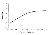
- FIG. 3 is a graph showing the relationship between the distance d between the propeller chips of the left and right sides of the ship according to the first embodiment of the present invention and the propulsion performance of the ship.
- the horizontal axis indicates the value of the distance d between the propeller chips of the starboard propeller 10R and the port propeller 10L.
- the vertical axis represents the propulsion performance index of the ship, and shows a normalized value assuming that the propulsion performance is 1.0 when the same stern hull 3 is propelled by a pair of propellers and main engine.
- the propulsion performance is horsepower performance, and the smaller the horsepower required to produce the same speed, the better the performance, that is, the better the fuel economy performance.
- the propulsion performance in order to improve the propulsion performance as compared with the uniaxial ship, the propulsion performance needs to be 1.0 or less. Therefore, the upper limit of the distance d between the propeller chips is preferably set to 1.0 m.
- FIG. 4 is a conceptual diagram schematically showing the relationship between the starboard propeller 10R, the port propeller 10L, and the vortex.
- longitudinal vortices V ⁇ b> 2 and V ⁇ b> 1 are generated in a region 80 in the vicinity of the center line C in the ship width direction.
- the rotation direction of the starboard propeller 10R and port propeller 10L of the twin-screw ship is at the upper part of the starboard propeller 10R and port propeller 10L.
- the outer rotations R2 and R1 rotate outward from the center C in the ship width direction.
- the starboard propeller 10R and the starboard propeller 10L can efficiently collect the longitudinal vortices V1 and V2 in the range of the regions S2 and S1 overlapping the region 80. And, as the distance d between the propeller chips is reduced, the combined area of the region S2 and the region S1 is increased, so that the propulsion performance can be further improved.
- the center height of the starboard propeller 10R and the portside propeller 10L need not be the same position. However, considering the maneuverability of the biaxial ship 1, the same position is preferable.
- the position of the tip portion 9 at the same height as the starboard propeller 10R and the starboard propeller 10L in the stern hull 3 is closer to the bow side than the position of the bow side end of the rotation surface of the starboard propeller 10R and the starboard propeller 10L. Preferably there is.
- the rudder 40 is provided behind the starboard propeller 10R and the starboard propeller 10L and on the center C in the ship width direction.
- the rudder 40 is disposed on the rear side (stern side) of the starboard propeller 10R and the starboard propeller 10L.
- the rudder 40 has a wing cross-sectional shape and is attached to a rudder shaft 41 that extends vertically downward from the bottom 4 of the stern hull 3.
- the rudder 40 rotates around the vertical axis together with the rudder shaft 41 to change the course direction of the biaxial ship 1.
- the front edge 40f of the rudder 40, the starboard propeller 10R, and the starboard propeller 10L be as close as possible. This is because the fast flow generated by the starboard propeller 10R and the portside propeller 10L flows into the rudder 40, and the steering effect is improved.
- the propeller diameters of the starboard propeller 10R and the starboard propeller 10L are Dp
- the distance L from the front edge 40fp is preferably 1.0 Dp or less.
- the starboard propeller 10R and the port propeller 10L are arranged close to the center C in the width direction of the ship.
- the longitudinal vortex in the vicinity of the center C in the width direction can be efficiently recovered, and the propulsion performance can be improved.
- the starboard propeller 10R and the starboard propeller 10L do not interfere with each other unlike the interlock propeller system. Thereby, the biaxial ship 1 can be easily manufactured.
- the distance L between the center position Pc of the port propeller 10L and the starboard propeller 10R and the front edge 40fp of the rudder 40 at the center height Ph of the port propeller 10L and the starboard propeller 10R was made to be 1.0 Dp or less.
- the front edge 40fp of the rudder 40 can be brought close to the starboard propeller 10R and the starboard propeller 10L, and the wake from the starboard propeller 10R and the starboard propeller 10L can flow into the rudder 40.
- the steering effect can be improved.
- the stern hull 3 can exhibit the above-described functions and effects particularly remarkably when the stern hull 3 has a uniaxial stern type stern structure.
- the uniaxial stern type stern structure can strengthen the inward vertical vortex in the vicinity of the center C in the width direction of the ship, compared with the case of having a skeg which is a biaxial stern type stern structure.
- the flow can be efficiently collected to improve the propulsion performance.
- the stern hull 3 of the biaxial ship 1 has a uniaxial stern structure, but the present invention is not limited to this.
- a skeg extending along the center C in the width direction may be provided in front of the rudder 40.
- FIG. 5 is a bottom view showing a configuration of a propulsion device for a close-biaxial ship having a shaft bracket according to a second embodiment of the present invention.
- FIG. 6 is an enlarged view of a main part of FIG. 5 and shows a cross-sectional shape of the strut of the shaft bracket.
- the biaxial ship 1 in this embodiment includes a starboard propeller 10 ⁇ / b> R and a port propeller 10 ⁇ / b> L provided in the same configuration as the first embodiment, and a rudder 40. I have.
- the starboard propeller shaft 12R and the starboard propeller shaft 12L are rotatably supported by the shaft brackets 13R and 13L in front of the starboard propeller 10R and the starboard propeller 10L.
- the struts 25R, 26R, 25L, and 26L of the shaft brackets 13R and 13L have a blade cross-sectional shape that is orthogonal to the direction extending from the ship bottom 4 toward the cylindrical support portions 14R and 14L. ing.
- the struts 25R, 26R, 25L, and 26L are formed to give a flow in a direction opposite to the rotational direction of the starboard propeller 10R and the port propeller 10L to the upper portions of the starboard propeller 10R and the port propeller 10L.
- the starboard propeller 10R and the port propeller 10L rotate outwardly from the ship width direction center C toward the outside R2, R1 at the upper part of the starboard propeller 10R and the port propeller 10L. Therefore, the struts 25R, 26R, 25L, and 26L are provided such that flows FR1 and FL1 are generated from the outer side in the ship width direction toward the center C side in the ship width direction at the upper part of the starboard propeller 10R and the port propeller 10L. Specifically, the struts 25R, 26R, 25L, and 26L are inclined so as to gradually approach the center C in the ship width direction from the front edge portions 25f and 26f toward the rear edge portions 25r and 26r rather than the propeller axial direction Sp. Is formed.
- the struts 25R, 26R, 25L, and 26L of the shaft brackets 13R and 13L have the blade cross-sectional shape, and the outer periphery R2, Flows FR1 and FL1 from the outer side in the ship width direction opposite to the rotation direction of the starboard propeller 10R and the port propeller 10L to the upper side of the ship width direction center C side are given to the upper portions of the starboard propeller 10R and the port propeller 10L rotating at R1. . Thereby, the speed of the rotation direction of the flow with respect to the port propeller 10L and the starboard propeller 10R is relatively increased.
- the wake that has passed through the struts 25R, 26R, 25L, and 26L of the shaft brackets 13R and 13L can be efficiently collected by the starboard propeller 10R and the portside propeller 10L, and the propulsion performance can be improved.
- the starboard propeller 10R and the port propeller 10L are arranged close to the ship width direction center C as in the first embodiment, so the ship width direction center C The nearby vertical vortex can be efficiently recovered, and the propulsion performance can be improved. Further, the starboard propeller 10R and the starboard propeller 10L do not interfere with each other unlike the interlock propeller system. Thereby, the biaxial ship 1 can be easily manufactured. Since the starboard propeller 10R and the port propeller 10L are arranged in parallel, risks such as excessive bearing force, expansion of the cavitation range, and occurrence of erosion in the rear propeller can be significantly suppressed as compared with the OLP method. Thus, according to the biaxial ship 1, it becomes possible to improve propulsion performance, suppressing generation
- the distance between the starboard propeller shaft 12R and the port propeller shaft 12L is gradually decreased toward the rear of the hull so as to have a horizontal rake.
- the starboard propeller shaft 12R, the starboard propeller shaft 12L, the port main machine 18L, and the starboard main machine 18R may be arranged by inclining the propeller axis direction Sp with respect to the center C of the ship width direction.
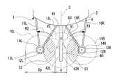
- FIG. 8 is a rear view of a propulsion device for a close-biaxial ship having a shaft bracket according to a third embodiment of the present invention.
- the biaxial ship 1 in this embodiment includes a starboard propeller 10 ⁇ / b> R and a port propeller 10 ⁇ / b> L provided in the same configuration as in the second embodiment, and a rudder 40.
- the starboard propeller shaft 12R and the starboard propeller shaft 12L are rotatably supported by the shaft brackets 13R and 13L in front of the starboard propeller 10R and the starboard propeller 10L.
- the cylindrical support portions 14R and 14L of the shaft brackets 13R and 13L are provided with one or more (four in the present embodiment) fins 45 extending radially on the outer peripheral portion of the lower portion thereof. .
- each fin 45 orthogonal to the direction extending from the cylindrical support portions 14R and 14L toward the outer peripheral side is the blade cross-sectional shape. Furthermore, each fin 45 is formed so as to give a flow in a direction opposite to the rotational direction of the starboard propeller 10R and the port propeller 10L to the lower portions of the starboard propeller 10R and the port propeller 10L. That is, the starboard propeller 10R and the starboard propeller 10L rotate from the outside toward the center C in the ship width direction at the lower part of the starboard propeller 10R and the port propeller 10L.
- the fins 45 are formed so that flows FR2 and FL2 are generated from the ship width direction center C side toward the ship width direction outer side in the lower part of the starboard propeller 10R and the port propeller 10L. Specifically, each fin 45 gradually moves away from the ship width direction center C toward the outer side in the ship width direction at the lower portion of the starboard propeller 10R and the port propeller 10L from the front edge portion 45f toward the rear edge portion 45r. Thus, it is formed to be inclined.
- the fins 45 provided on the shaft brackets 13R and 13L have a wing cross-sectional shape, and the starboard propeller 10R and the port propeller are provided.
- a spiral flow FR2, FL2 from the ship width direction center C side opposite to the rotation direction of the starboard propeller 10R and the port propeller 10L to the outer side in the ship width direction can be applied to the lower part of 10L.
- the speed of the rotation direction of the flow with respect to the port propeller 10L and the starboard propeller 10R is relatively increased.
- the wake that has passed through the fins 45 of the shaft brackets 13R, 13L can be efficiently recovered by the starboard propeller 10R and the port propeller 10L, and the propulsion performance can be improved.
- the starboard propeller 10R and the port propeller 10L are arranged close to the vicinity of the center C in the width direction as in the first and second embodiments.
- the vertical vortex in the vicinity of the direction center C can be efficiently recovered, and the propulsion performance can be improved.
- the starboard propeller 10R and the starboard propeller 10L do not interfere with each other unlike the interlock propeller system.
- the biaxial ship 1 can be easily manufactured. Since the starboard propeller 10R and the port propeller 10L are arranged in parallel, risks such as excessive bearing force, expansion of the cavitation range, and occurrence of erosion in the rear propeller can be significantly suppressed as compared with the OLP method.
- the struts 25R, 26R, 25L, and 26L are the same as those in the second embodiment.
- the struts 15R, 16R, and the like are not limited to the above. 15L and 16L may be provided.
Abstract
Description
本願は、2014年11月18日に出願された特願2014-233258号について優先権を主張し、その内容をここに援用する。 The present invention relates to a propulsion device for a proximity biaxial ship having a shaft bracket and a ship.
This application claims priority in Japanese Patent Application No. 2014-233258 for which it applied on November 18, 2014, and uses the content here.
船舶が一機の主機と一基のプロペラとを備えた、いわゆる一軸船の場合、船舶が大型化すると、一基のみのプロペラに作用する荷重度が増加する。十分な推進力を得るには、プロペラの回転速度を高めたり、プロペラの径を大きくしたりする必要がある。これにより、プロペラの周速が速くなるので、プロペラ翼端近傍の圧力が下がって、水中に気泡が生じる現象であるキャビテーションが過大に発生することがある。キャビテーションが発生すると、船尾船底を通じて船体が振動する。また、キャビテーションによってプロペラにエロージョンが生じることがあり、プロペラの耐久性に悪影響を及ぼす。 A marine vessel propulsion apparatus generally obtains propulsive force by rotating a propeller by a main engine.
In the case of a so-called single-shaft ship in which the ship includes one main engine and one propeller, when the ship is enlarged, the degree of load acting on only one propeller increases. In order to obtain sufficient thrust, it is necessary to increase the rotation speed of the propeller or increase the diameter of the propeller. As a result, since the peripheral speed of the propeller is increased, the pressure in the vicinity of the propeller blade tip decreases, and cavitation, which is a phenomenon in which bubbles are generated in water, may occur excessively. When cavitation occurs, the hull vibrates through the stern bottom. In addition, cavitation may cause erosion of the propeller, which adversely affects the durability of the propeller.
このうち、OLP方式では、二基のプロペラを前後にずらして配置し、船尾から見た場合に二基のプロペラの少なくとも一部が重なるように配置する。OLP方式を採用することで推進性能が一軸船から5~10%程度改善できる。
インターロックプロペラ方式では、一方のプロペラの翼と翼との間に他方のプロペラの翼が入るように配置する。
プロペラを左右並列する方式では、プロペラを船長方向の同じ位置に並べて配置する。 Examples of arranging two propellers at the stern include an overlapping propeller (OLP) system, an interlock propeller system, and a system in which propellers are arranged in parallel on the left and right.
Among these, in the OLP system, the two propellers are arranged to be shifted back and forth so that at least a part of the two propellers overlap when viewed from the stern. By adopting the OLP method, the propulsion performance can be improved by about 5 to 10% from that of a single-axle ship.
In the interlock propeller system, the wings of the other propeller are placed between the wings of one propeller.
In the system in which the propellers are arranged side by side, the propellers are arranged at the same position in the captain direction.
また、前方のプロペラの回転により、速度の速い回転流が新たに形成されるため、後方のプロペラは非常に複雑な流れの中で動作する必要があり、必然的にキャビテーションが発生する範囲が広がってしまう。その結果、過大な振動が発生する恐れがある。更に、前方のプロペラのプロペラ翼の先端からチップボルテックスキャビテーション(翼端渦キャビテーション)を発生した場合、発生した気泡が後方のプロペラのプロペラ翼面上で破裂するなどして、そのプロペラ翼にエロージョンを発生させる可能性もある。 However, when the OLP method is used, the propeller arranged at the rear of the OLP system moves between the fast flow accelerated by the forward propeller and the slow flow near the center of the ship width direction (ship width direction) during one rotation. Pass alternately. Therefore, the load applied to the propeller blades of the rear propeller varies greatly. As a result, in the biaxial ship using the OLP method, the bearing force acting on the propeller shaft bearing of the rear propeller may be excessive as compared with the monoaxial ship.
In addition, since the rotation of the front propeller newly forms a high-speed rotational flow, the rear propeller needs to operate in a very complicated flow, and the range in which cavitation occurs inevitably increases. End up. As a result, excessive vibration may occur. In addition, when tip vortex cavitation is generated from the tip of the propeller blade of the front propeller, the generated bubbles burst on the propeller blade surface of the rear propeller, causing erosion to the propeller blade. There is also a possibility of generating.
このように構成することで、舵の前縁を右舷プロペラおよび左舷プロペラに近づけることができ、右舷プロペラおよび左舷プロペラからの後流を舵面に確実に当てることができる。これによって、舵効きおよび推進性能を向上させることができる。 In the propulsion device for a proximity biaxial ship having the shaft bracket, when the propeller diameter of the port propeller and the starboard propeller is Dp, the center position of the port propeller and the starboard propeller, and the port propeller and the starboard propeller You may make it the distance with the front edge of the said rudder in center height be 1.0 Dp or less.
By configuring in this way, the rudder front edge can be brought close to the starboard propeller and port propeller, and the wake from the starboard propeller and port propeller can be reliably applied to the control surface. Thereby, the steering effect and the propulsion performance can be improved.
このような構成によれば、一軸船型の船尾構造を有する場合において、上記した各態様における作用効果を特に顕著に奏することができる。また、一軸船型の船尾構造は、二軸船型の船尾構造であるスケグを備える場合に比較し、船幅方向中心の近傍における内回りの縦渦を強めることができ、外回りに回転する右舷プロペラおよび左舷プロペラにおいて、流れを効率よく回収して推進性能を向上させることができる。 In the propulsion device for a proximity biaxial ship having the shaft bracket, the stern hull may have a uniaxial stern type stern structure.
According to such a structure, when it has a uniaxial stern type stern structure, the effect in each aspect mentioned above can be show | played especially notably. In addition, the stern type stern structure can strengthen the inward vertical vortex near the center in the width direction of the ship, compared to the case with the skeg, which is a biaxial stern structure. In the propeller, the flow can be efficiently collected to improve the propulsion performance.
このように構成することで、ストラットにより、左舷プロペラおよび右舷プロペラの回転方向とは反対方向の流れが付与されるので、左舷プロペラおよび右舷プロペラ(10R)に対する流れの回転方向の速度が相対的に高まる。これによって、右舷プロペラ(10R)および左舷プロペラにおいて、より多くの前進方向の推力を発揮させることが可能となり、推進性能を向上させることができる。 In the propulsion device for a proximity biaxial ship having the shaft bracket, the shaft bracket includes a shaft support portion that rotatably supports the propeller shaft of the port propeller and the starboard propeller, the shaft support portion, and the stern hull. Connecting struts, wherein the struts are configured to give a flow in a direction opposite to the rotation direction of the port propellers and starboard propellers to the upper portions of the port propellers and starboard propellers. May be.
With this configuration, the strut imparts a flow in a direction opposite to the rotation direction of the port propeller and starboard propeller, so that the velocity in the rotation direction of the flow relative to the port propeller and starboard propeller (10R) is relatively Rise. Accordingly, it becomes possible to exert more thrust in the forward direction in the starboard propeller (10R) and the port propeller, and the propulsion performance can be improved.
このように構成することで、フィンにより、左舷プロペラおよび右舷プロペラの回転方向とは反対方向の流れが付与されるので、左舷プロペラおよび右舷プロペラに対する流れの回転方向の速度が相対的に高まる。これによって、右舷プロペラおよび左舷プロペラにおいて、より多くの前進方向の推力を発揮させることが可能となり、推進性能を向上させることができる。 In the propulsion device for a proximity biaxial ship having the shaft bracket, the shaft bracket includes a shaft support portion that rotatably supports the propeller shaft of the port propeller and the starboard propeller, the shaft support portion, and the stern hull. A strut to be connected, and the shaft support portion includes one or more fins extending radially on an outer peripheral portion of a lower portion thereof, and each of the fins with respect to a lower portion of the port propeller and the starboard propeller. The port propeller and the starboard propeller may be formed so as to give a flow in a direction opposite to the rotation direction.
With this configuration, the fins impart a flow in a direction opposite to the rotation direction of the port and the starboard propellers, so that the speed of the flow in the rotation direction relative to the port and the starboard propellers is relatively increased. As a result, the starboard propeller and the port propeller can exhibit more thrust in the forward direction, and the propulsion performance can be improved.
このような構成によれば、右舷プロペラおよび左舷プロペラを船幅方向中心の近傍に近接させて配置することで、推進性能の向上を図ることができる。右舷プロペラおよび左舷プロペラにおけるベアリングフォース、キャビテーション、エロージョンの発生などのリスクを大幅に抑制することができる。 According to a second aspect of the present invention, a ship is provided with a propulsion device for a proximity biaxial ship having the shaft bracket according to any one of the above aspects.
According to such a configuration, the propulsion performance can be improved by arranging the starboard propeller and the port propeller in the vicinity of the center in the ship width direction. Risks such as bearing forces, cavitation and erosion in starboard and port propellers can be greatly reduced.
(第一実施形態)
図1は、第一実施形態のシャフトブラケットを有する近接二軸船の推進装置の構成を示す下面図である。図2は、推進装置の構成を示す側面図である。
ここでは、船舶として、多軸船の一種である一軸船型の船尾構造を有する二軸船(船舶、近接二軸船)1を例に説明する。
図1に示すように、この実施形態の二軸船1の推進装置は、右舷プロペラ10Rと、左舷プロペラ10Lと、舵40と、を備えている。 Hereinafter, a propulsion device for a close-biaxial ship having a shaft bracket according to an embodiment of the present invention and a ship will be described with reference to the drawings.
(First embodiment)
FIG. 1 is a bottom view showing a configuration of a propulsion device for a close-biaxial ship having a shaft bracket according to a first embodiment. FIG. 2 is a side view showing the configuration of the propulsion device.
Here, a biaxial ship (a ship, a close biaxial ship) 1 having a uniaxial stern type stern structure, which is a kind of multi-axis ship, will be described as an example.
As shown in FIG. 1, the propulsion device of the
左舷プロペラ10Lは、船尾船体3の船底4の左舷側の下方に設けられている。左舷プロペラ10Lは、左舷プロペラ軸12Lの一端に接続されている。船尾船体3の内部の左舷側には、左舷主機18Lが設けられている。左舷プロペラ軸12Lは、船底4に設けられたボッシング11Lを通して船尾船体3内部に貫通し、他端が左舷主機18Lに接続されている。左舷主機18Lは、左舷プロペラ軸12Lを介して左舷プロペラ10Lを回転させる。 The
The
シャフトブラケット13R、13Lは、右舷プロペラ軸12R、左舷プロペラ軸12Lを回転自在に支持する筒状支持部14R、14Lと、筒状支持部14R、14Lから上方に向けてV字状に延び、上端が船尾船体3の船底4に接続された複数のストラット15R、16R、15L、16Lと、を備えている。 As shown in FIGS. 1 and 2, the
The
ここで、右舷プロペラ10Rと左舷プロペラ10Lとの距離を、船幅方向中心C側における右舷プロペラ10Rの最外周部と左舷プロペラ10Lの最外周部との間隔であるプロペラチップ間距離dで表す。プロペラチップ間距離dは、プロペラ翼同士の接触の恐れがなく、かつ、縦渦を捉えられるように右舷プロペラ10Rと左舷プロペラ10Lとを船幅方向中心Cに近く配置できるよう、なるべく小さく設定するのが好ましい。プロペラチップ間距離dは、以下のようにして決定される。 The
Here, the distance between the
図3において、横軸は、右舷プロペラ10Rと左舷プロペラ10Lとのプロペラチップ間距離dの値を示している。縦軸は、船舶の推進性能指標であり、同じ船尾船体3に一組のプロペラおよび主機で推進させる一軸船とした場合の推進性能を1.0として正規化した値を示している。ここで、推進性能は馬力性能のことであり、同一速力を出すために必要な馬力が小さいほど性能が良い、すなわち燃費性能が良いことになる。従って、縦軸の推進性能指標の数値が小さくなるほど推進性能が良く、数値が大きくなるほど推進性能が悪い。したがって、一軸船と比較して推進性能を向上させるためには、推進性能を1.0以下にする必要がある。したがって、プロペラチップ間距離dの上限を、1.0mと設定するのが好ましい。 FIG. 3 is a graph showing the relationship between the distance d between the propeller chips of the left and right sides of the ship according to the first embodiment of the present invention and the propulsion performance of the ship.
In FIG. 3, the horizontal axis indicates the value of the distance d between the propeller chips of the
右舷プロペラ10Rと左舷プロペラ10Lは、その領域80と重なる領域S2、S1の範囲で、効率良く縦渦V1,V2を回収できる。そして、プロペラチップ間距離dを小さくすればするほど、領域S2及び領域S1を併せた面積が大きくなるため、推進性能をより向上させることができる。 This is explained, for example, as follows. FIG. 4 is a conceptual diagram schematically showing the relationship between the
The
舵40は、右舷プロペラ10Rおよび左舷プロペラ10Lよりも後方側(船尾側)に配置されている。舵40は、翼断面形状で、船尾船体3の船底4から鉛直下方に延びる舵軸41に取り付けられている。舵40は、舵軸41とともに鉛直軸線回りに回転し、二軸船1の針路方向を変更する。 The
The
このようにして、二軸船1によれば、キャビテーションやエロージョンなどの発生を抑制しつつ、推進性能を向上させることが可能となる。 Therefore, according to the propulsion device and the vessel of the proximity biaxial ship having the shaft bracket of the first embodiment described above, the
Thus, according to the
なお、上記第一実施形態では、二軸船1の船尾船体3が、一軸船型の船尾構造を有するものとしたが、これに限らない。船尾船体3において、舵40の前方に、船幅方向中心Cに沿って延びるスケグを備えるようにしてもよい。 (Modification of the first embodiment)
In the first embodiment, the
次に、本発明にかかるシャフトブラケットを有する近接二軸船の推進装置および船舶の第二実施形態について説明する。以下に説明する第二実施形態においては、第一実施形態とシャフトブラケット13R、13Lの構成のみが異なるので、第一実施形態と同一部分に同一符号を付して説明するとともに、重複説明を省略する。
図5は、本発明の第二実施形態のシャフトブラケットを有する近接二軸船の推進装置の構成を示す下面図である。図6は、図5の要部拡大図であり、シャフトブラケットのストラットの断面形状を示す図である。図7は、本発明の第二実施形態のシャフトブラケットを有する近接二軸船の推進装置を後方から見た図である。
図5、図6、図7に示すように、この実施形態における二軸船1は、上記第一実施形態と同様の構成で設けられた右舷プロペラ10Rおよび左舷プロペラ10Lと、舵40と、を備えている。 (Second embodiment)
Next, a propulsion device for a proximity biaxial ship having a shaft bracket according to the present invention and a second embodiment of the ship will be described. In the second embodiment described below, since only the configuration of the
FIG. 5 is a bottom view showing a configuration of a propulsion device for a close-biaxial ship having a shaft bracket according to a second embodiment of the present invention. FIG. 6 is an enlarged view of a main part of FIG. 5 and shows a cross-sectional shape of the strut of the shaft bracket. FIG. 7 is a rear view of a propulsion device for a close-biaxial ship having a shaft bracket according to a second embodiment of the present invention.
As shown in FIGS. 5, 6, and 7, the
このようにして、二軸船1によれば、キャビテーションやエロージョンなどの発生を抑制しつつ、推進性能を向上させることが可能となる。 Further, according to the propulsion device of the
Thus, according to the
次に、本発明にかかるシャフトブラケットを有する近接二軸船の推進装置および船舶の第三実施形態について説明する。以下に説明する第三実施形態においては、第二実施形態とシャフトブラケット13R、13Lの構成のみが異なるので、第二実施形態と同一部分に同一符号を付して説明するとともに、重複説明を省略する。
図8は、本発明の第三実施形態のシャフトブラケットを有する近接二軸船の推進装置を後方から見た図である。
図8に示すように、この実施形態における二軸船1は、上記第二実施形態と同様の構成で設けられた右舷プロペラ10Rおよび左舷プロペラ10Lと、舵40と、を備えている。 (Third embodiment)
Next, a propulsion device for a proximity biaxial ship having a shaft bracket according to the present invention and a third embodiment of the ship will be described. In the third embodiment described below, since only the configuration of the
FIG. 8 is a rear view of a propulsion device for a close-biaxial ship having a shaft bracket according to a third embodiment of the present invention.
As shown in FIG. 8, the
このようにして、二軸船1によれば、キャビテーションやエロージョンなどの発生を抑制しつつ、推進性能を向上させることが可能となる。 Further, according to the propulsion device of the
Thus, according to the
なお、本発明は、上述した実施形態に限定されるものではなく、本発明の趣旨を逸脱しない範囲において、上述した実施形態に種々の変更を加えたものを含む。すなわち、実施形態で挙げた具体的な形状や構成等は一例にすぎず、適宜変更が可能である。 (Other variations)
Note that the present invention is not limited to the above-described embodiments, and includes various modifications made to the above-described embodiments without departing from the spirit of the present invention. That is, the specific shapes, configurations, and the like given in the embodiment are merely examples, and can be changed as appropriate.
3 船尾船体
4 船底
9 先端部
10L 左舷プロペラ
10R 右舷プロペラ
11L,11R ボッシング
12L 左舷プロペラ軸
12R 右舷プロペラ軸
13R,13L シャフトブラケット
14R,14L 筒状支持部
15R,15L、16R,16L、25R,25L、26R,26L ストラット
18L 左舷主機
18R 右舷主機
40 舵
40f、40fp 前縁
41 舵軸
45 フィン
80 領域
C 船幅方向中心
d プロペラチップ間距離
Ls 基準線
V1,V2 縦渦 1 Biaxial ship (ship, adjacent biaxial ship)
3
Claims (6)
- 船尾船体に設けられた左舷プロペラおよび右舷プロペラと、
前記左舷プロペラおよび前記右舷プロペラの後方において、前記船尾船体の船幅方向中心に配置された1つの舵、または左舷舵および右舷舵からなる2つの舵と、
前記左舷プロペラおよび前記右舷プロペラの前方にそれぞれ設けられ、前記左舷プロペラおよび前記右舷プロペラのプロペラ軸を回転自在に支持するシャフトブラケットと、を備え、
前記船幅方向中心側における前記左舷プロペラのプロペラ翼の先端と前記右舷プロペラのプロペラ翼の先端との距離は、0mより大きく1.0m以下とされ、
前記左舷プロペラおよび前記右舷プロペラの回転方向は、前記左舷プロペラおよび前記右舷プロペラの上部において船幅方向中心側から外側に向かって回転する外回りとされているシャフトブラケットを有する近接二軸船の推進装置。 Port and starboard propellers on the stern hull,
Behind the port propeller and starboard propeller, one rudder arranged at the center of the stern hull width direction, or two rudders consisting of a port rudder and a starboard rudder,
A shaft bracket provided in front of the port propeller and the starboard propeller, respectively, and rotatably supporting a propeller shaft of the port propeller and the starboard propeller;
The distance between the tip of the propeller wing of the port propeller and the tip of the propeller wing of the starboard propeller at the center in the width direction of the ship is greater than 0 m and 1.0 m or less.
The propulsion device for a close-biaxial ship having a shaft bracket that rotates outwardly from the center in the width direction of the ship at the upper part of the port propeller and the starboard propeller in the rotation direction of the port propeller and the starboard propeller. . - 前記左舷プロペラおよび前記右舷プロペラのプロペラ直径をDpとしたとき、前記左舷プロペラ及び前記右舷プロペラの中心位置と、前記左舷プロペラおよび前記右舷プロペラの中心高さにおける前記舵の前縁との距離が、1.0Dp以下である請求項1に記載のシャフトブラケットを有する近接二軸船の推進装置。 When the propeller diameter of the port propeller and starboard propeller is Dp, the distance between the center position of the port propeller and starboard propeller and the leading edge of the rudder at the center height of the port propeller and starboard propeller is: The propulsion device for a close-biaxial ship having a shaft bracket according to claim 1, wherein the propulsion device has a shaft bracket of 1.0 Dp or less.
- 前記船尾船体は、一軸船型の船尾構造を有する請求項1又は2に記載のシャフトブラケットを有する近接二軸船の推進装置。 3. A propulsion device for a proximity biaxial ship having a shaft bracket according to claim 1 or 2, wherein the stern hull has a uniaxial stern type stern structure.
- 前記シャフトブラケットは、前記左舷プロペラおよび前記右舷プロペラの前記プロペラ軸を回転自在に支持する軸支持部と、前記軸支持部と船尾船体とを接続するストラットと、を備え、
前記ストラットは、前記左舷プロペラおよび前記右舷プロペラの上部に対し、前記左舷プロペラおよび前記右舷プロペラの回転方向とは反対方向の流れを与えるように形成されている請求項1から3の何れか一項に記載のシャフトブラケットを有する近接二軸船の推進装置。 The shaft bracket includes a shaft support portion that rotatably supports the propeller shaft of the port propeller and the starboard propeller, and a strut that connects the shaft support portion and the stern hull.
The strut is formed so as to give a flow in a direction opposite to a rotational direction of the port propeller and the starboard propeller to an upper portion of the port propeller and the starboard propeller. A propulsion device for a close-biaxial ship having the shaft bracket described in 1. - 前記シャフトブラケットは、前記左舷プロペラおよび前記右舷プロペラの前記プロペラ軸を回転自在に支持する軸支持部と、前記軸支持部と船尾船体とを接続するストラットと、を備え、
前記軸支持部は、その下部の外周部に、放射状に延びる1枚以上のフィンを備え、前記各フィンは、前記左舷プロペラおよび前記右舷プロペラの下部に対し、前記左舷プロペラおよび前記右舷プロペラの回転方向とは反対方向の流れを与えるように形成されている請求項1から4の何れか一項に記載のシャフトブラケットを有する近接二軸船の推進装置。 The shaft bracket includes a shaft support portion that rotatably supports the propeller shaft of the port propeller and the starboard propeller, and a strut that connects the shaft support portion and the stern hull.
The shaft support portion includes one or more radially extending fins on an outer peripheral portion of a lower portion thereof, and the fins rotate the port propeller and the starboard propeller with respect to the lower portions of the port propeller and the starboard propeller. The propulsion device for a close-biaxial ship having a shaft bracket according to any one of claims 1 to 4, wherein the propulsion device has a shaft bracket according to any one of claims 1 to 4. - 請求項1から5の何れか一項に記載のシャフトブラケットを有する近接二軸船の推進装置を備える船舶。 A ship equipped with a propulsion device for a close-biaxial ship having the shaft bracket according to any one of claims 1 to 5.
Priority Applications (4)
| Application Number | Priority Date | Filing Date | Title |
|---|---|---|---|
| US14/907,757 US20160325810A1 (en) | 2014-11-18 | 2015-02-06 | Propulsion device for proximity twin-screw vessel having shaft bracket and ship |
| CN201580001416.8A CN105813939A (en) | 2014-11-18 | 2015-02-06 | Propulsion device for neighboring-twin-screw ship having shaft brackets, and ship |
| EP15823304.9A EP3045382B1 (en) | 2014-11-18 | 2015-02-06 | Propulsion device for neighboring-twin-screw ship having shaft brackets, and ship |
| KR1020167002329A KR101891006B1 (en) | 2014-11-18 | 2015-02-06 | Propulsion device for proximity twin-screw vessel having shaft bracket and ship |
Applications Claiming Priority (2)
| Application Number | Priority Date | Filing Date | Title |
|---|---|---|---|
| JP2014-233258 | 2014-11-18 | ||
| JP2014233258A JP6226241B2 (en) | 2014-11-18 | 2014-11-18 | Proximity biaxial ship propulsion device with shaft bracket, ship |
Publications (1)
| Publication Number | Publication Date |
|---|---|
| WO2016080002A1 true WO2016080002A1 (en) | 2016-05-26 |
Family
ID=56013571
Family Applications (1)
| Application Number | Title | Priority Date | Filing Date |
|---|---|---|---|
| PCT/JP2015/053372 WO2016080002A1 (en) | 2014-11-18 | 2015-02-06 | Propulsion device for neighboring-twin-screw ship having shaft brackets, and ship |
Country Status (6)
| Country | Link |
|---|---|
| US (1) | US20160325810A1 (en) |
| EP (1) | EP3045382B1 (en) |
| JP (1) | JP6226241B2 (en) |
| KR (1) | KR101891006B1 (en) |
| CN (2) | CN105813939A (en) |
| WO (1) | WO2016080002A1 (en) |
Families Citing this family (2)
| Publication number | Priority date | Publication date | Assignee | Title |
|---|---|---|---|---|
| JP6246960B1 (en) * | 2017-01-25 | 2017-12-13 | 三菱重工業株式会社 | Ship propulsion device and ship |
| CN109334925A (en) * | 2018-10-22 | 2019-02-15 | 谭国祯 | Vector push type submarine |
Citations (8)
| Publication number | Priority date | Publication date | Assignee | Title |
|---|---|---|---|---|
| JPS4737316B1 (en) * | 1968-10-26 | 1972-09-20 | ||
| JPS59202991A (en) * | 1983-05-02 | 1984-11-16 | Mitsubishi Heavy Ind Ltd | Shaft bracket having slanted wing cross section |
| JPS6072800U (en) * | 1983-10-27 | 1985-05-22 | 三菱重工業株式会社 | Botting structure with fins for multi-shaft ships |
| JPH0315300U (en) * | 1989-06-27 | 1991-02-15 | ||
| WO2006095774A1 (en) | 2005-03-11 | 2006-09-14 | Kabushiki Kaisha Kawasaki Zosen | Stern structure of ship |
| US7798875B1 (en) * | 2006-10-20 | 2010-09-21 | Brunswick Corporation | Helical marine strut |
| JP2011098678A (en) * | 2009-11-09 | 2011-05-19 | Mitsubishi Heavy Ind Ltd | Propulsion device for marine vessel |
| JP2011121569A (en) * | 2009-12-14 | 2011-06-23 | Mitsubishi Heavy Ind Ltd | Propulsion performance improving device of ship |
Family Cites Families (3)
| Publication number | Priority date | Publication date | Assignee | Title |
|---|---|---|---|---|
| US2974628A (en) * | 1958-10-20 | 1961-03-14 | Robert W Erlbacher | Twisted strut construction for marine bearing with forwardly mounted propeller |
| JP4707569B2 (en) * | 2006-01-17 | 2011-06-22 | 流体テクノ有限会社 | Ship thrust-enhancing shaft bracket |
| JP2011098639A (en) * | 2009-11-05 | 2011-05-19 | Mitsubishi Heavy Ind Ltd | Stern structure of marine vessel |
-
2014
- 2014-11-18 JP JP2014233258A patent/JP6226241B2/en active Active
-
2015
- 2015-02-06 US US14/907,757 patent/US20160325810A1/en not_active Abandoned
- 2015-02-06 EP EP15823304.9A patent/EP3045382B1/en active Active
- 2015-02-06 CN CN201580001416.8A patent/CN105813939A/en active Pending
- 2015-02-06 WO PCT/JP2015/053372 patent/WO2016080002A1/en active Application Filing
- 2015-02-06 KR KR1020167002329A patent/KR101891006B1/en active IP Right Grant
- 2015-02-06 CN CN202010248964.3A patent/CN111516841A/en active Pending
Patent Citations (8)
| Publication number | Priority date | Publication date | Assignee | Title |
|---|---|---|---|---|
| JPS4737316B1 (en) * | 1968-10-26 | 1972-09-20 | ||
| JPS59202991A (en) * | 1983-05-02 | 1984-11-16 | Mitsubishi Heavy Ind Ltd | Shaft bracket having slanted wing cross section |
| JPS6072800U (en) * | 1983-10-27 | 1985-05-22 | 三菱重工業株式会社 | Botting structure with fins for multi-shaft ships |
| JPH0315300U (en) * | 1989-06-27 | 1991-02-15 | ||
| WO2006095774A1 (en) | 2005-03-11 | 2006-09-14 | Kabushiki Kaisha Kawasaki Zosen | Stern structure of ship |
| US7798875B1 (en) * | 2006-10-20 | 2010-09-21 | Brunswick Corporation | Helical marine strut |
| JP2011098678A (en) * | 2009-11-09 | 2011-05-19 | Mitsubishi Heavy Ind Ltd | Propulsion device for marine vessel |
| JP2011121569A (en) * | 2009-12-14 | 2011-06-23 | Mitsubishi Heavy Ind Ltd | Propulsion performance improving device of ship |
Also Published As
| Publication number | Publication date |
|---|---|
| CN111516841A (en) | 2020-08-11 |
| KR101891006B1 (en) | 2018-09-28 |
| JP6226241B2 (en) | 2017-11-08 |
| CN105813939A (en) | 2016-07-27 |
| EP3045382A1 (en) | 2016-07-20 |
| EP3045382A4 (en) | 2017-11-29 |
| US20160325810A1 (en) | 2016-11-10 |
| KR20160072088A (en) | 2016-06-22 |
| JP2016097687A (en) | 2016-05-30 |
| EP3045382B1 (en) | 2020-08-12 |
Similar Documents
| Publication | Publication Date | Title |
|---|---|---|
| JPWO2015114916A1 (en) | Steering device and steering method thereof | |
| JP2014040169A (en) | Contra-rotating propeller propulsion system ship | |
| JP5582761B2 (en) | Ship propulsion device | |
| KR20180026363A (en) | Vessel | |
| JP5453625B2 (en) | Ship with biaxial propeller | |
| JP6226241B2 (en) | Proximity biaxial ship propulsion device with shaft bracket, ship | |
| JP6422020B2 (en) | Twin skeg ship | |
| JP6246960B1 (en) | Ship propulsion device and ship | |
| JP6554743B2 (en) | Closed biaxial ship with finned rudder, ship | |
| KR101159205B1 (en) | Rudder for ship and ship including the same | |
| WO2018025644A1 (en) | Ship | |
| WO2021014919A1 (en) | Stern fin | |
| JP7422839B2 (en) | rudder | |
| JP6493691B2 (en) | Ship | |
| JP2005239083A (en) | Pod type propulsion unit and vessel provided with this | |
| JP7107668B2 (en) | rudder | |
| JP2022147294A (en) | Vessel propulsion device and vessel | |
| JP2011031858A (en) | Pod propelling device | |
| JP2022141345A (en) | steering gear | |
| JP2020185810A (en) | Rudder and ship with it | |
| JP2012045968A (en) | Rudder for ship, ship and method for designing the ship | |
| JP2011098696A (en) | Propulsion device and ship using the same | |
| JP2011098702A (en) | Propulsion device and ship using the same | |
| JP2014151773A (en) | Twin-skeg type hull structure |
Legal Events
| Date | Code | Title | Description |
|---|---|---|---|
| REEP | Request for entry into the european phase |
Ref document number: 2015823304 Country of ref document: EP |
|
| WWE | Wipo information: entry into national phase |
Ref document number: 14907757 Country of ref document: US Ref document number: 2015823304 Country of ref document: EP |
|
| WWE | Wipo information: entry into national phase |
Ref document number: 1020167002329 Country of ref document: KR |
|
| 121 | Ep: the epo has been informed by wipo that ep was designated in this application |
Ref document number: 15823304 Country of ref document: EP Kind code of ref document: A1 |
|
| NENP | Non-entry into the national phase |
Ref country code: DE |