WO2016076342A1 - Dispositif d'affichage tête haute - Google Patents
Dispositif d'affichage tête haute Download PDFInfo
- Publication number
- WO2016076342A1 WO2016076342A1 PCT/JP2015/081683 JP2015081683W WO2016076342A1 WO 2016076342 A1 WO2016076342 A1 WO 2016076342A1 JP 2015081683 W JP2015081683 W JP 2015081683W WO 2016076342 A1 WO2016076342 A1 WO 2016076342A1
- Authority
- WO
- WIPO (PCT)
- Prior art keywords
- mirror
- head
- display device
- display
- shielding
- Prior art date
Links
- 229910052751 metal Inorganic materials 0.000 claims description 49
- 239000002184 metal Substances 0.000 claims description 49
- 229920005989 resin Polymers 0.000 claims description 38
- 239000011347 resin Substances 0.000 claims description 38
- XAGFODPZIPBFFR-UHFFFAOYSA-N aluminium Chemical group [Al] XAGFODPZIPBFFR-UHFFFAOYSA-N 0.000 claims description 17
- 229910052782 aluminium Inorganic materials 0.000 claims description 16
- 239000000463 material Substances 0.000 claims description 15
- 230000003287 optical effect Effects 0.000 claims description 13
- 230000003313 weakening effect Effects 0.000 claims description 3
- 239000004744 fabric Substances 0.000 claims 1
- 229920000515 polycarbonate Polymers 0.000 description 6
- 239000004417 polycarbonate Substances 0.000 description 6
- 230000000903 blocking effect Effects 0.000 description 5
- 238000002844 melting Methods 0.000 description 4
- 230000008018 melting Effects 0.000 description 4
- 238000000034 method Methods 0.000 description 4
- 230000005855 radiation Effects 0.000 description 4
- 238000012546 transfer Methods 0.000 description 4
- 239000006059 cover glass Substances 0.000 description 3
- 238000013461 design Methods 0.000 description 3
- 238000010586 diagram Methods 0.000 description 3
- 230000000694 effects Effects 0.000 description 3
- 238000000465 moulding Methods 0.000 description 3
- 229910000838 Al alloy Inorganic materials 0.000 description 2
- 239000012790 adhesive layer Substances 0.000 description 2
- 238000007796 conventional method Methods 0.000 description 2
- 239000011521 glass Substances 0.000 description 2
- 239000005020 polyethylene terephthalate Substances 0.000 description 2
- 229920000139 polyethylene terephthalate Polymers 0.000 description 2
- 239000000758 substrate Substances 0.000 description 2
- 206010037660 Pyrexia Diseases 0.000 description 1
- 229920000122 acrylonitrile butadiene styrene Polymers 0.000 description 1
- 239000000853 adhesive Substances 0.000 description 1
- 230000001070 adhesive effect Effects 0.000 description 1
- 238000013459 approach Methods 0.000 description 1
- 230000015556 catabolic process Effects 0.000 description 1
- 238000006731 degradation reaction Methods 0.000 description 1
- 238000004512 die casting Methods 0.000 description 1
- 239000003822 epoxy resin Substances 0.000 description 1
- 238000002347 injection Methods 0.000 description 1
- 239000007924 injection Substances 0.000 description 1
- 239000004973 liquid crystal related substance Substances 0.000 description 1
- 230000000873 masking effect Effects 0.000 description 1
- 239000003973 paint Substances 0.000 description 1
- 229920000647 polyepoxide Polymers 0.000 description 1
- -1 polyethylene terephthalate Polymers 0.000 description 1
- 238000007788 roughening Methods 0.000 description 1
- 238000003892 spreading Methods 0.000 description 1
- 238000003860 storage Methods 0.000 description 1
- 229920001187 thermosetting polymer Polymers 0.000 description 1
Images


Classifications
-
- B—PERFORMING OPERATIONS; TRANSPORTING
- B60—VEHICLES IN GENERAL
- B60K—ARRANGEMENT OR MOUNTING OF PROPULSION UNITS OR OF TRANSMISSIONS IN VEHICLES; ARRANGEMENT OR MOUNTING OF PLURAL DIVERSE PRIME-MOVERS IN VEHICLES; AUXILIARY DRIVES FOR VEHICLES; INSTRUMENTATION OR DASHBOARDS FOR VEHICLES; ARRANGEMENTS IN CONNECTION WITH COOLING, AIR INTAKE, GAS EXHAUST OR FUEL SUPPLY OF PROPULSION UNITS IN VEHICLES
- B60K35/00—Instruments specially adapted for vehicles; Arrangement of instruments in or on vehicles
-
- G—PHYSICS
- G02—OPTICS
- G02B—OPTICAL ELEMENTS, SYSTEMS OR APPARATUS
- G02B27/00—Optical systems or apparatus not provided for by any of the groups G02B1/00 - G02B26/00, G02B30/00
- G02B27/01—Head-up displays
Definitions
- the present invention relates to a head-up display device with a measure against sunlight.
- Patent Document 1 As shown in FIG. 1 of Patent Document 1, the image light beam emitted upward from the HUD display (2) (the numbers in parentheses indicate the symbols described in Patent Document 1. The same applies hereinafter) It hits the inner surface of (5) and is reflected and imaged in front of the driver (Patent Document 1, paragraph [0012]). When not in use, external light (sunlight) is prevented from reaching the HUD display (2) by blocking the optical path with the shutter (4). Thus, damage to the HUD display (2) can be prevented (Patent Document 1, paragraph [0006]).
- the head-up display device becomes expensive and large. Moreover, since the shutter (4) is open when not in use, that is, during operation, it is not possible to prevent sunlight from entering at this time. There is a need for a structure that can prevent the incidence of sunlight at all times, including during operation.
- a reflective polarizing film (21) (the numbers in parentheses indicate the symbols described in Patent Document 2. The same applies hereinafter) is interposed in the optical path. Due to the presence of the reflective polarizing film (21), the temperature of the liquid crystal shell (16) does not rise even when sunlight (b) is incident (Patent Document 2, paragraph [0013]). In addition, the reflective polarizing film (21) is stuck on the upper surface of the glass substrate (22).
- Patent Document 2 it is possible to always take measures against sunlight.
- the reflective polarizing film (21) and the glass substrate (22) are essential, the head-up display device is likely to be expensive and large.
- the head-up display device is required to be reduced in size and cost, a device capable of taking measures against sunlight without using a shutter or a reflective polarizing film is desired.
- JP 2003-237411 A Japanese Patent No. 4114194
- This invention makes it a subject to provide the head-up display apparatus which can take a sunlight countermeasure, without using a shutter and a reflective polarizing film.
- the inventors of the present invention tried to improve the head-up display device described in FIG. 1 of Patent Document 2 previously proposed by the inventors.
- the improved apparatus 100 will be described with reference to FIG.
- a head-up display device 100 shown in FIG. 1 is a primary improvement type device, and in contrast to the device described in Patent Document 2, between the concave mirror 101 and the plane mirror 102, the shielding plate 104 and the optical path 103 are very close to each other.
- the shielding plate 105 is extended.
- the sunlight 106 is reflected by the concave mirror 101, hits the shielding plate 104, stops, and does not have to worry about reaching the display 107.
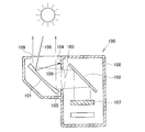
- the present inventors have made further improvements, completed a secondary improved device, and succeeded in taking good solar countermeasures. That is, the head-up display device 10 shown in FIG. 2 is a basic configuration diagram of the secondary improvement device.
- the head-up display device 10 includes a display 13 that is disposed on the light source 11 and emits display light 12, and a first mirror that reflects the display light 12 emitted from the display 13.
- a case 20 for storage is a case 20 for storage.
- the first concave mirror 14 has a curvature (reciprocal of the radius) that causes the reflected display light 15 to cross up and down before reaching the second concave mirror 16, and the second concave mirror 16 receives the received display light. Plays a reflective role. That is, the first concave mirror 14 has a curvature such that the focal point of the first concave mirror 14 is located between the first concave mirror 14 and the second concave mirror 16. In other words, the distance from the first concave mirror 14 to the second concave mirror 16 is set longer than the focal length of the first concave mirror 14.
- the case 20 includes a first shielding part 23 and a second shielding part 24 that extend to the vicinity of the crossing point 22 that crosses the optical path 21 between the first and second concave mirrors 14 and 16.
- the lower end (front end) of the first shielding part 23 connects at least the upper end part P1 of the reflection area of the display light 12 in the first concave mirror 14 and the upper end part P2 of the reflection area of the display light 15 in the second concave mirror 16. It is located on the cross point 22 side (lower side) with respect to the elliptical line segment L1.
- the upper end (front end) of the second shielding part 24 connects at least the lower end part P3 of the reflection area of the display light 12 in the first concave mirror 14 and the lower end part P4 of the reflection area of the display light 15 in the second concave mirror 16. It is located closer to the cross point 22 (upper side) than the ellipse segment L2.
- first and second shielding parts 23 and 24 extend so that their tips approach each other. The closer the tips are, the higher the shielding property of the external light 25, which is desirable. That is, it is desirable that the tips of each other are close to the cross point 22 (focal point).
- the end of the reflection region coincides with the end of the mirror surface formed in a concave shape. If a masking tape or the like is provided on the mirror surface, the exposed end of the mirror surface can be referred to as the end of the reflection region.
- first and second shielding parts 23 and 24 play a role of blocking outside light
- other parts of the case 20 parts away from the shielding parts 23 and 24, for example, bottom parts, hereinafter referred to as general parts 26. Higher temperature. Therefore, it is desired that the first and second shielding parts 23 and 24 have higher heat resistance than the general part 26 of the case 20.
- the heat-resistant temperature there is a correlation between the heat-resistant temperature and the melting temperature. That is, if the melting temperature is high, the heat resistant temperature is high, and if the melting temperature is low, the heat resistant temperature tends to be low. Table 1 lists the melting temperature as a reference value for the heat-resistant temperature. The heat-resistant temperature is shown only for the epoxy resin that is a thermosetting resin.
- Combination Example 1 and Combination Example 2 were obtained by combining resins. In combination example 3, resin and light metal were combined.
- the first and second shielding parts 23 and 24 are made of aluminum die-cast products, but the aluminum die-cast products are integrated into the general part 26 of the case 20 by insert molding, bonding, screwing or an equivalent bonding method. To do.
- the thermal conductivity may be increased.
- the thermal conductivity is increased, the movement of heat is promoted, and as a result, the temperatures of the first and second shielding parts 23 and 24 are lowered.
- the strength against heat of the first and second shielding parts 23 and 24 can be increased.
- first and second shielding portions 23 and 24 are reflective surfaces, reflected light is generated, and the reflected light returns to the second concave mirror 16 and is reflected and strikes the first and second shielding portions 23 and 24. It is worried that it goes to the first concave mirror 14 without.
- anti-reflection treatment films 27 and 27 that weaken or block the reflection of external light are formed on the first and second shielding portions 23 and 24 at least at the site where the external light 25 hits.
- the antireflection treatment film 27 is suitably black alumite if the base material is black paint and aluminum.
- the antireflection treatment may be a treatment for roughening a sandblasted surface.
- the invention according to claim 1 includes the display 13 that emits the display light 12, the first mirror 14 that reflects the display light 12 emitted from the display 13, and the first mirror 14.
- the first mirror 14 Is a first concave mirror having a curvature that causes the reflected display light 15 to cross up and down before reaching the second mirror 16, and the second mirror 16 reflects the received display light.
- the case 20 includes a first shielding portion 23 and a second shielding portion 24 that extend to the vicinity of the cross point 2 that crosses the optical path 21 between the first and second concave mirrors. ,in front The outside light 25 that enters the case 20 from the outside of the case 20, is reflected by the second concave mirror, and travels toward the first concave mirror is shielded by the first and second shielding portions 23 and 24. .
- the first and second shielding portions 23 and 24 are formed of a material having a higher thermal conductivity than the general portion 26 of the case 20.
- the first and second shielding portions 23 and 24 are formed of a material having a heat resistant temperature higher than that of the general portion 26 of the case 20.
- the first and second shielding portions 23, 24 are subjected to an antireflection treatment for weakening or blocking the reflection of the external light at least at the site where the external light hits.
- the case 20 includes a center frame that supports the first and second concave mirrors 14 and 16 and includes a second shielding part 24, and a first shielding part 23 that is attached on the center frame.
- An upper cover and a lower cover attached under the center frame.
- the center frame is a metal molded product
- the lower cover is a resin molded product
- the upper cover is a resin molded product or a metal molded product.
- the metal molded product is an aluminum die-cast product.
- the case includes a center frame that supports the first and second concave mirrors and includes a second shielding portion, and an upper cover that is attached on the center frame and includes the first shielding portion.
- the upper cover is a resin molded product, A metal plate is disposed on at least the upper surface of the first shielding part, The density of the resin used for the material of the resin molded product is smaller than the density of the metal plate, The heat resistance temperature of the metal plate is higher than the heat resistance temperature of the resin.
- the first mirror is a first concave mirror having a curvature that causes the reflected display light to cross up and down before reaching the second mirror. At the crossing point where the light crosses, the width of the optical path becomes small.
- the first shielding portion and the second shielding portion are extended near the cross point, and external light such as sunlight is shielded by the first shielding portion and the second shielding portion. Most of the outside light is shielded by the first and second shielding parts, and cannot reach the first concave mirror or the display part. Therefore, according to the present invention, there is provided a head-up display device capable of taking measures against sunlight without using a shutter or a reflective polarizing film.
- the first and second shielding parts are formed of a material having a higher thermal conductivity than the general part of the case. Since the heat conductivity is high, heat transfer in the first and second shielding portions can be promoted, and the temperature of the first and second shielding portions can be lowered. That is, it is possible to suppress heat from staying in the first and second shielding portions that are likely to become high temperature.
- the first and second shielding portions are formed of a material having a heat resistant temperature higher than that of the general portion of the case.
- the first and second shielding portions are subjected to an antireflection treatment for weakening or blocking the reflection of the external light at least at the site where the external light hits. There is no fear that the external light hitting the first and second shielding parts will return to the second concave mirror.
- the case includes a center frame that supports the first and second concave mirrors and includes a second shielding portion, an upper cover that is mounted on the center frame and includes the first shielding portion, and a center frame. A lower cover, which is mounted underneath. If the first concave mirror and the second concave mirror are attached to separate covers, it is necessary to adjust the optical axis in consideration of the dimensional error of each cover, and this adjustment becomes troublesome. In the present invention, since the first concave mirror and the second concave mirror are attached to a common center frame, the optical axes of the first concave mirror and the second concave mirror can be easily adjusted.
- the center frame is a metal molded product
- the lower cover is a resin molded product
- the upper cover is a resin molded product or a metal molded product. If it is a metal molded product, it is rich in rigidity. Since the first and second concave mirrors are attached to the rigid center frame, the optical axis is well maintained.
- a metal molded product generally has a higher heat resistant temperature and higher thermal conductivity than a resin molded product.
- the metal molded product is an aluminum die-cast product.
- the metal molded product may be a metal press product, but the shape of the press product cannot be complicated. If it is a cast product, it can be a complicated shape, but it is difficult to reduce the thickness. In this respect, die-cast products can be thinned and thinned, and are suitable for complex shapes. In addition, if aluminum, it is lightweight and the weight of the apparatus can be reduced.
- a metal plate is disposed on the upper surface of the first shielding part which is a resin molded product.
- a 1st shielding part is a site
- external light strikes the upper surface of the first shielding part.
- sunlight is given.
- High heat resistance is calculated
- the overall head-up display device is desired to be lightweight.
- the resin used for the upper cover has a lower density (lower) than the metal plate. For this reason, the weight of the head-up display device can be reduced by using the upper cover as a resin molded product.
- the metal plate has a higher heat resistance temperature (heat resistance) than the resin used for the upper cover. For this reason, heat resistance can be improved by arrange
- FIG. 3 is a basic configuration diagram of a second improved product, that is, a head-up display device according to the present invention.
- 1 is an exploded view of a head-up display device according to Embodiment 1 of the present invention. It is sectional drawing of the head-up display apparatus which concerns on Example 1 of this invention. It is a figure explaining the shielding effect of the 1st and 2nd shielding part. It is a figure explaining the heat flow in the 1st, 2nd shielding part. It is a figure explaining the example of a change of a center frame. It is sectional drawing of the head-up display apparatus which concerns on Example 2 of this invention. It is a disassembled perspective view of an upper cover and a metal plate. It is a figure explaining the example of a change of a metal plate.
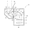
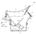
- the case 20 includes a center frame 30 that supports the first and second concave mirrors 14 and 16 and includes a second shielding portion 24, and the center frame 30.
- the upper cover 50 is provided with the first shielding portion 23 attached thereto, and the lower cover 55 is attached under the center frame 30.
- the center frame 30 is an aluminum die-cast product having mounting flanges 31 and 31 on the outer periphery and a second shielding part 24 extending obliquely upward inside.
- a stay 32 is welded to the center frame 30, and the first concave mirror 14 is fixed to the stay 32 with an adhesive layer 33.
- the second concave mirror 16 is fixed to the stays 34 to 36 welded to the inner surface of the center frame 30 with adhesive layers 37 to 39.
- the center frame 30 is an aluminum die-cast product, the strength is much higher than that of a resin molded product, and the rigidity is high. Since the first and second concave mirrors 14 and 16 and the display 13 are collectively attached to the rigid center frame 30, it is difficult to adjust these optical axes. Furthermore, the rigid center frame 30 is attached to the vehicle by attachment flanges 31 and 31. If the cover is entirely made of resin, the rigidity may be insufficient and the optical axis may need to be readjusted. On the other hand, since the head-up display device 10 of the embodiment is rich in rigidity, the concern is small.
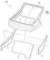
- the upper cover 50 is, for example, a polycarbonate molded product, and includes a cover glass 51 on the upper surface and integrally includes a first shielding portion 23 that extends obliquely downward.
- the lower cover 55 is a bottomed cylindrical body that opens upward, and is, for example, an ABS resin molded product and includes a printed circuit board 56.
- the lower cover 55 is attached to the center frame 30 with screws 57 and 57 from below, and the upper cover 50 is attached with screws 52 from above.
- the head-up display device 10 shown in FIG. 4 is completed.
- the display light 12 emitted from the display unit 13 is reflected by the first concave mirror 14, and the display light 15 reflected by the first concave mirror 14 passes between the first and second shielding parts 23 and 24,
- the second concave mirror 16 is reached.
- the display light 17 reflected by the second concave mirror 16 rises and reaches the vehicle windshield 66 (projection unit 66 on which the reflected display light 17 is projected).
- the external light 25 represented by sunlight passes through the cover glass 51, is reflected by the second concave mirror 16, and is reflected by the first shielding unit 23. Shielded. Since the 1st shielding part 23 is a polycarbonate excellent in heat resistance, the intensity
- the external light 25 passes through the cover glass 51, is reflected by the second concave mirror 16, and is shielded by the second shielding part 24, as shown in FIG. Since the 2nd shielding part 24 is aluminum which is further excellent in heat resistance, the intensity
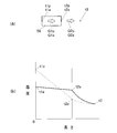
- PC resin has a thermal conductivity of about 0.2 W / m / K.
- ADC12 aluminum die-cast product
- FIG. 6A is a diagram for explaining a very simple heat transfer model, in which one end of a polycarbonate (PC) resin rod 59 has a high temperature t1p and a lower temperature t2p than the other end t1p (t2p is higher than the atmospheric temperature t3).
- PC polycarbonate
- Q1p is calculated by the following equation: thermal conductivity ⁇ p ⁇ bar length ⁇ (t1p ⁇ t2p).
- Q2p is calculated by the heat transfer coefficient cp ⁇ (t2p ⁇ t3).
- one end of the rod 59 of the aluminum die-cast product is in a thermally steady state at a high temperature t1a and a temperature t2a lower than t1a at the other end (t2a is higher than the atmospheric temperature t3).
- the heat Q1a flowing inside the bar 59 is equal to the heat Q2a released from the other end of the bar 59 to the atmosphere.
- Q1a is calculated as follows: thermal conductivity ⁇ a ⁇ bar length ⁇ (t1a ⁇ t2a).
- Q2a is calculated by the heat transfer coefficient ca ⁇ (t2a ⁇ t3).
- the first shielding part 23 is also made of the same aluminum die cast as the second shielding part 24 or light metal.
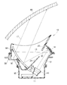
- an aluminum die-cast product 63 in which heat radiation fins 61 are integrally formed on the first shielding part 23 is manufactured in advance, and the aluminum die-cast product 63 is placed in a cavity of a molding die, and a PC resin 64 is placed in the cavity.
- injection so-called insert molding can be performed.
- the heat is transmitted through the first shielding part 23 and reaches the radiation fin 61. Since the radiation fin 61 has a large heat radiation area, it actively releases heat toward the atmosphere.
- the entire upper cover 50 may be made of aluminum die casting or light metal. ⁇ Example 2>
- FIG. 8 shows a cross-sectional configuration of the head-up display device of the second embodiment.
- FIG. 8 is shown corresponding to FIG.
- a metal plate 71 is disposed on the upper surface of the first shielding part 23.
- Other basic configurations are the same as those of the head-up display device 10 according to the first embodiment (see FIG. 4).
- omitted about the part which is common in Example 1, while using a code
- the upper cover 50A is a resin molded product, and for example, a mixed resin material of polycarbonate and polyethylene terephthalate (PET) can be used.
- PET polyethylene terephthalate
- Aluminum or aluminum alloy can be used for the material of the metal plate 71.
- the resin used as the material of the resin molded product is smaller than the density of the metal used for the metal plate 71.
- the heat resistance temperature of the resin used for the material is lower than the heat resistance temperature of the metal used for the metal plate 71. That is, the heat resistance temperature of the metal plate 71 is higher than the heat resistance temperature of the resin. If these conditions are satisfied, an arbitrary material can be selected as the resin or metal.
- the metal plates 71 are attached to the upper cover 50A.
- the metal plates 71 are respectively attached to the upper surface of the first shielding portion 23 and the inner surfaces of the left and right side surfaces of the upper cover 50A extending forward from the left and right ends of the upper surface. These can be referred to as design surfaces that are visible from the outside. That is, the metal plate 71 is disposed on the design surface. The design property can be further improved by spreading the metal plate 71 on the visible portion.
- the metal plate 71 can be disposed on the upper cover 50A by an arbitrary method such as sticking with a double-sided tape, bonding with an adhesive, screwing with a screw, or locking with a fixing hook.
- a metal plate 71 is disposed on the upper surface of the first shielding part 23 that is a resin molded product.
- the 1st shielding part 23 is a site
- sunlight is given. High heat resistance is required for the first shielding part 23 that is exposed to sunlight.
- the head-up display device 10A as a whole is desired to be lightweight.
- the resin used for the upper cover 50 ⁇ / b> A has a density smaller (lower) than that of the metal plate 71.
- the weight of the head-up display device 10A can be reduced by using the upper cover 50A as a resin molded product.
- the metal plate 71 has a heat resistant temperature (heat resistance) higher than that of the resin used for the upper cover 50A. For this reason, heat resistance can be improved by arrange
- FIG. 10 shows a modified example of the head-up display device 10B in which the metal plate 71B is modified. That is, the metal plate 71B can be configured by a single plate. Even in this case, the predetermined effect of the present invention can be obtained. Moreover, when comprised by 1 sheet, since the seam of metal plates does not exist compared with the case where comprised by several board, designability can be improved more.
- the head-up display device of the present invention is suitable for a passenger car, but may be applied to general vehicles, ships, and aircraft. That is, the present invention is not limited to the examples as long as the operations and effects of the present invention are exhibited.
- the head-up display device of the present invention is suitable for a vehicle including a windshield.
Landscapes
- Physics & Mathematics (AREA)
- Engineering & Computer Science (AREA)
- General Physics & Mathematics (AREA)
- Optics & Photonics (AREA)
- Chemical & Material Sciences (AREA)
- Combustion & Propulsion (AREA)
- Transportation (AREA)
- Mechanical Engineering (AREA)
- Instrument Panels (AREA)
Abstract
La présente invention a pour but de fournir un dispositif d'affichage tête haute capable de contrer la lumière du soleil sans utiliser d'obturateur ni de film polarisant de type à réflexion. Un premier miroir concave (14) présente une courbure pour amener la lumière d'affichage réfléchie (15) à le croiser verticalement avant d'atteindre un second miroir (16), et un second miroir concave (16) sert à réfléchir la lumière d'affichage reçue. Un boîtier (20) est pourvu d'un premier écran (23) et d'un second écran (24) s'étendant à proximité d'un point d'intersection (22) pour prendre en sandwich un trajet de lumière (21) entre les premier et second miroirs concaves (14, 16). Les premier et second écrans (23, 24) peuvent empêcher la lumière externe (25) d'entrer dans le boîtier (20) depuis l'extérieur du boîtier (20) et de poursuivre vers le premier miroir concave (14) après avoir été réfléchie par le second miroir concave (16).
Priority Applications (3)
| Application Number | Priority Date | Filing Date | Title |
|---|---|---|---|
| EP15858147.0A EP3220186B1 (fr) | 2014-11-12 | 2015-11-11 | Dispositif d'affichage tête haute |
| US15/526,078 US10114218B2 (en) | 2014-11-12 | 2015-11-11 | Head up display device |
| CN201580061256.6A CN107111133A (zh) | 2014-11-12 | 2015-11-11 | 平视显示装置 |
Applications Claiming Priority (4)
| Application Number | Priority Date | Filing Date | Title |
|---|---|---|---|
| JP2014-229919 | 2014-11-12 | ||
| JP2014229919 | 2014-11-12 | ||
| JP2015212180A JP6579319B2 (ja) | 2014-11-12 | 2015-10-28 | ヘッドアップディスプレイ装置 |
| JP2015-212180 | 2015-10-28 |
Publications (1)
| Publication Number | Publication Date |
|---|---|
| WO2016076342A1 true WO2016076342A1 (fr) | 2016-05-19 |
Family
ID=55954421
Family Applications (1)
| Application Number | Title | Priority Date | Filing Date |
|---|---|---|---|
| PCT/JP2015/081683 WO2016076342A1 (fr) | 2014-11-12 | 2015-11-11 | Dispositif d'affichage tête haute |
Country Status (1)
| Country | Link |
|---|---|
| WO (1) | WO2016076342A1 (fr) |
Cited By (2)
| Publication number | Priority date | Publication date | Assignee | Title |
|---|---|---|---|---|
| WO2017195740A1 (fr) * | 2016-05-09 | 2017-11-16 | 日本精機株式会社 | Dispositif d'affichage tête haute |
| JP2018120029A (ja) * | 2017-01-23 | 2018-08-02 | 日本精機株式会社 | ヘッドアップディスプレイ装置 |
Citations (3)
| Publication number | Priority date | Publication date | Assignee | Title |
|---|---|---|---|---|
| JPS62275845A (ja) * | 1986-05-23 | 1987-11-30 | Nissan Motor Co Ltd | 車両用表示装置 |
| JPH09159986A (ja) * | 1995-12-13 | 1997-06-20 | Kansei Corp | 車両用情報表示装置 |
| JP2004226469A (ja) * | 2003-01-20 | 2004-08-12 | Denso Corp | 車両用ヘッドアップディスプレイ装置 |
-
2015
- 2015-11-11 WO PCT/JP2015/081683 patent/WO2016076342A1/fr active Application Filing
Patent Citations (3)
| Publication number | Priority date | Publication date | Assignee | Title |
|---|---|---|---|---|
| JPS62275845A (ja) * | 1986-05-23 | 1987-11-30 | Nissan Motor Co Ltd | 車両用表示装置 |
| JPH09159986A (ja) * | 1995-12-13 | 1997-06-20 | Kansei Corp | 車両用情報表示装置 |
| JP2004226469A (ja) * | 2003-01-20 | 2004-08-12 | Denso Corp | 車両用ヘッドアップディスプレイ装置 |
Non-Patent Citations (1)
| Title |
|---|
| See also references of EP3220186A4 * |
Cited By (2)
| Publication number | Priority date | Publication date | Assignee | Title |
|---|---|---|---|---|
| WO2017195740A1 (fr) * | 2016-05-09 | 2017-11-16 | 日本精機株式会社 | Dispositif d'affichage tête haute |
| JP2018120029A (ja) * | 2017-01-23 | 2018-08-02 | 日本精機株式会社 | ヘッドアップディスプレイ装置 |
Similar Documents
| Publication | Publication Date | Title |
|---|---|---|
| JP6579319B2 (ja) | ヘッドアップディスプレイ装置 | |
| JP6642172B2 (ja) | ヘッドアップディスプレイ装置 | |
| JP6769481B2 (ja) | ヘッドアップディスプレイ装置 | |
| JP6819679B2 (ja) | ヘッドアップディスプレイ装置 | |
| JP6563711B2 (ja) | ヘッドアップディスプレイ装置 | |
| JP2018198145A (ja) | 発熱装置 | |
| US20190285884A1 (en) | Display device and apparatus | |
| WO2016076342A1 (fr) | Dispositif d'affichage tête haute | |
| US20180215239A1 (en) | Vehicular optical system | |
| JP7115471B2 (ja) | ヘッドアップディスプレイ装置 | |
| WO2019151482A1 (fr) | Dispositif d'affichage tête haute | |
| JP2016055713A (ja) | 車両用ヘッドアップディスプレイ装置 | |
| JP2011246056A (ja) | 車載カメラ | |
| JP2015169816A (ja) | 光学部品の結露防止構造、及び、ヘッドアップディスプレイ装置 | |
| CN114660817B (zh) | 抬头显示器、交通工具及抬头显示方法 | |
| JP2018087775A (ja) | 車両用表示装置 | |
| JP7068223B2 (ja) | ヘッドアップディスプレイ | |
| JP2019003102A (ja) | 表示装置 | |
| JP2019174781A (ja) | 反射光学素子およびステレオカメラ装置 | |
| JP2018198375A (ja) | 発熱装置 | |
| JP2019008090A (ja) | ヘッドアップディスプレイ装置 | |
| WO2020166306A1 (fr) | Composant optique et dispositif d'affichage d'image l'utilisant | |
| JP6428078B2 (ja) | 車両用ヘッドアップディスプレイ装置 | |
| JP2018198144A (ja) | 発熱装置 | |
| JP2019185012A (ja) | 撮影装置 |
Legal Events
| Date | Code | Title | Description |
|---|---|---|---|
| 121 | Ep: the epo has been informed by wipo that ep was designated in this application |
Ref document number: 15858147 Country of ref document: EP Kind code of ref document: A1 |
|
| WWE | Wipo information: entry into national phase |
Ref document number: 15526078 Country of ref document: US |
|
| NENP | Non-entry into the national phase |
Ref country code: DE |
|
| REEP | Request for entry into the european phase |
Ref document number: 2015858147 Country of ref document: EP |