WO2016076324A1 - 内燃機関の冷却制御装置及びその冷却制御方法 - Google Patents
内燃機関の冷却制御装置及びその冷却制御方法 Download PDFInfo
- Publication number
- WO2016076324A1 WO2016076324A1 PCT/JP2015/081639 JP2015081639W WO2016076324A1 WO 2016076324 A1 WO2016076324 A1 WO 2016076324A1 JP 2015081639 W JP2015081639 W JP 2015081639W WO 2016076324 A1 WO2016076324 A1 WO 2016076324A1
- Authority
- WO
- WIPO (PCT)
- Prior art keywords
- cooling
- internal combustion
- combustion engine
- temperature
- radiator fan
- Prior art date
- Legal status (The legal status is an assumption and is not a legal conclusion. Google has not performed a legal analysis and makes no representation as to the accuracy of the status listed.)
- Ceased
Links
Images




Classifications
-
- F—MECHANICAL ENGINEERING; LIGHTING; HEATING; WEAPONS; BLASTING
- F01—MACHINES OR ENGINES IN GENERAL; ENGINE PLANTS IN GENERAL; STEAM ENGINES
- F01P—COOLING OF MACHINES OR ENGINES IN GENERAL; COOLING OF INTERNAL-COMBUSTION ENGINES
- F01P7/00—Controlling of coolant flow
- F01P7/02—Controlling of coolant flow the coolant being cooling-air
- F01P7/026—Thermostatic control
-
- F—MECHANICAL ENGINEERING; LIGHTING; HEATING; WEAPONS; BLASTING
- F01—MACHINES OR ENGINES IN GENERAL; ENGINE PLANTS IN GENERAL; STEAM ENGINES
- F01P—COOLING OF MACHINES OR ENGINES IN GENERAL; COOLING OF INTERNAL-COMBUSTION ENGINES
- F01P11/00—Component parts, details, or accessories not provided for in, or of interest apart from, groups F01P1/00 - F01P9/00
- F01P11/14—Indicating devices; Other safety devices
- F01P11/16—Indicating devices; Other safety devices concerning coolant temperature
-
- F—MECHANICAL ENGINEERING; LIGHTING; HEATING; WEAPONS; BLASTING
- F01—MACHINES OR ENGINES IN GENERAL; ENGINE PLANTS IN GENERAL; STEAM ENGINES
- F01P—COOLING OF MACHINES OR ENGINES IN GENERAL; COOLING OF INTERNAL-COMBUSTION ENGINES
- F01P1/00—Air cooling
- F01P1/06—Arrangements for cooling other engine or machine parts
-
- F—MECHANICAL ENGINEERING; LIGHTING; HEATING; WEAPONS; BLASTING
- F01—MACHINES OR ENGINES IN GENERAL; ENGINE PLANTS IN GENERAL; STEAM ENGINES
- F01P—COOLING OF MACHINES OR ENGINES IN GENERAL; COOLING OF INTERNAL-COMBUSTION ENGINES
- F01P3/00—Liquid cooling
- F01P3/20—Cooling circuits not specific to a single part of engine or machine
-
- F—MECHANICAL ENGINEERING; LIGHTING; HEATING; WEAPONS; BLASTING
- F01—MACHINES OR ENGINES IN GENERAL; ENGINE PLANTS IN GENERAL; STEAM ENGINES
- F01P—COOLING OF MACHINES OR ENGINES IN GENERAL; COOLING OF INTERNAL-COMBUSTION ENGINES
- F01P5/00—Pumping cooling-air or liquid coolants
- F01P5/10—Pumping liquid coolant; Arrangements of coolant pumps
- F01P5/12—Pump-driving arrangements
-
- F—MECHANICAL ENGINEERING; LIGHTING; HEATING; WEAPONS; BLASTING
- F01—MACHINES OR ENGINES IN GENERAL; ENGINE PLANTS IN GENERAL; STEAM ENGINES
- F01P—COOLING OF MACHINES OR ENGINES IN GENERAL; COOLING OF INTERNAL-COMBUSTION ENGINES
- F01P7/00—Controlling of coolant flow
- F01P7/02—Controlling of coolant flow the coolant being cooling-air
- F01P7/04—Controlling of coolant flow the coolant being cooling-air by varying pump speed, e.g. by changing pump-drive gear ratio
-
- F—MECHANICAL ENGINEERING; LIGHTING; HEATING; WEAPONS; BLASTING
- F01—MACHINES OR ENGINES IN GENERAL; ENGINE PLANTS IN GENERAL; STEAM ENGINES
- F01P—COOLING OF MACHINES OR ENGINES IN GENERAL; COOLING OF INTERNAL-COMBUSTION ENGINES
- F01P7/00—Controlling of coolant flow
- F01P7/14—Controlling of coolant flow the coolant being liquid
- F01P7/16—Controlling of coolant flow the coolant being liquid by thermostatic control
- F01P7/164—Controlling of coolant flow the coolant being liquid by thermostatic control by varying pump speed
-
- F—MECHANICAL ENGINEERING; LIGHTING; HEATING; WEAPONS; BLASTING
- F02—COMBUSTION ENGINES; HOT-GAS OR COMBUSTION-PRODUCT ENGINE PLANTS
- F02D—CONTROLLING COMBUSTION ENGINES
- F02D41/00—Electrical control of supply of combustible mixture or its constituents
- F02D41/02—Circuit arrangements for generating control signals
- F02D41/04—Introducing corrections for particular operating conditions
- F02D41/042—Introducing corrections for particular operating conditions for stopping the engine
-
- F—MECHANICAL ENGINEERING; LIGHTING; HEATING; WEAPONS; BLASTING
- F01—MACHINES OR ENGINES IN GENERAL; ENGINE PLANTS IN GENERAL; STEAM ENGINES
- F01P—COOLING OF MACHINES OR ENGINES IN GENERAL; COOLING OF INTERNAL-COMBUSTION ENGINES
- F01P5/00—Pumping cooling-air or liquid coolants
- F01P5/10—Pumping liquid coolant; Arrangements of coolant pumps
- F01P5/12—Pump-driving arrangements
- F01P2005/125—Driving auxiliary pumps electrically
-
- F—MECHANICAL ENGINEERING; LIGHTING; HEATING; WEAPONS; BLASTING
- F01—MACHINES OR ENGINES IN GENERAL; ENGINE PLANTS IN GENERAL; STEAM ENGINES
- F01P—COOLING OF MACHINES OR ENGINES IN GENERAL; COOLING OF INTERNAL-COMBUSTION ENGINES
- F01P2031/00—Fail safe
- F01P2031/30—Cooling after the engine is stopped
-
- F—MECHANICAL ENGINEERING; LIGHTING; HEATING; WEAPONS; BLASTING
- F02—COMBUSTION ENGINES; HOT-GAS OR COMBUSTION-PRODUCT ENGINE PLANTS
- F02D—CONTROLLING COMBUSTION ENGINES
- F02D29/00—Controlling engines, such controlling being peculiar to the devices driven thereby, the devices being other than parts or accessories essential to engine operation, e.g. controlling of engines by signals external thereto
- F02D29/02—Controlling engines, such controlling being peculiar to the devices driven thereby, the devices being other than parts or accessories essential to engine operation, e.g. controlling of engines by signals external thereto peculiar to engines driving vehicles; peculiar to engines driving variable pitch propellers
-
- F—MECHANICAL ENGINEERING; LIGHTING; HEATING; WEAPONS; BLASTING
- F02—COMBUSTION ENGINES; HOT-GAS OR COMBUSTION-PRODUCT ENGINE PLANTS
- F02M—SUPPLYING COMBUSTION ENGINES IN GENERAL WITH COMBUSTIBLE MIXTURES OR CONSTITUENTS THEREOF
- F02M26/00—Engine-pertinent apparatus for adding exhaust gases to combustion-air, main fuel or fuel-air mixture, e.g. by exhaust gas recirculation [EGR] systems
- F02M26/13—Arrangement or layout of EGR passages, e.g. in relation to specific engine parts or for incorporation of accessories
- F02M26/22—Arrangement or layout of EGR passages, e.g. in relation to specific engine parts or for incorporation of accessories with coolers in the recirculation passage
- F02M26/23—Layout, e.g. schematics
- F02M26/28—Layout, e.g. schematics with liquid-cooled heat exchangers
-
- F—MECHANICAL ENGINEERING; LIGHTING; HEATING; WEAPONS; BLASTING
- F02—COMBUSTION ENGINES; HOT-GAS OR COMBUSTION-PRODUCT ENGINE PLANTS
- F02M—SUPPLYING COMBUSTION ENGINES IN GENERAL WITH COMBUSTIBLE MIXTURES OR CONSTITUENTS THEREOF
- F02M26/00—Engine-pertinent apparatus for adding exhaust gases to combustion-air, main fuel or fuel-air mixture, e.g. by exhaust gas recirculation [EGR] systems
- F02M26/65—Constructional details of EGR valves
- F02M26/72—Housings
- F02M26/73—Housings with means for heating or cooling the EGR valve
-
- F—MECHANICAL ENGINEERING; LIGHTING; HEATING; WEAPONS; BLASTING
- F02—COMBUSTION ENGINES; HOT-GAS OR COMBUSTION-PRODUCT ENGINE PLANTS
- F02N—STARTING OF COMBUSTION ENGINES; STARTING AIDS FOR SUCH ENGINES, NOT OTHERWISE PROVIDED FOR
- F02N11/00—Starting of engines by means of electric motors
- F02N11/08—Circuits specially adapted for starting of engines
- F02N11/0814—Circuits specially adapted for starting of engines comprising means for controlling automatic idle-start-stop
Definitions
- the present invention relates to a cooling control apparatus and a cooling control method for controlling cooling an internal combustion engine by circulating cooling water by an electric pump and supplying cooling air to a radiator by an electric fan.
- Patent Document 1 Since the cooling performance of the internal combustion engine (engine) is affected by the outside air temperature, in Patent Document 1, after stopping the engine, in addition to the temperature of the cooling water and the voltage of the battery, the electric pump and the electric The fan is being controlled. In Patent Document 1, when the ignition switch is turned off, the electric pump and the electric fan are operated, and after the electric pump is stopped, the electric fan is stopped.
- Patent Document 1 does not consider the detection error of the water temperature sensor at the time of restart from the idle stop and the delay in detection response to the temperature change of the water temperature sensor. For this reason, there is still room for improvement from the viewpoint of achieving both improvement in cooling effect and reduction in power consumption.
- the water temperature sensor cannot accurately measure the water temperature if the cooling water is not flowing due to temperature variations in the pipes or the like, if the electric pump is stopped while the engine is stopped, the detection error increases at the time of restart.
- the time constant of the temperature change of the cylinder head portion is about three times as fast as the detected temperature of the water temperature sensor, the detection response of the water temperature sensor is delayed with respect to the temperature drop due to engine stop. As a result, when the engine is restarted, the ignition timing is excessively corrected in the retarding direction in order to avoid knocking, and torque is reduced and fuel consumption is deteriorated.
- the present invention has been made in view of the above circumstances, and an object of the present invention is to provide a cooling control device for an internal combustion engine and a cooling control method therefor capable of reducing power consumption while improving the cooling effect. It is in.
- a cooling control apparatus for an internal combustion engine includes an electric pump that circulates a cooling medium in a cooling medium passage formed in the internal combustion engine, a radiator that cools the cooling medium, and a radiator fan.
- the radiator fan and the electric pump are driven to cool the internal combustion engine, and the temperature of the cooling medium is lower than when the engine is stopped.
- the radiator fan is stopped while the pump is operating.
- the cooling control method for an internal combustion engine according to the present invention includes an electric pump that circulates a cooling medium in a cooling medium passage formed in the internal combustion engine, a radiator that cools the cooling medium, and a radiator fan.
- a cooling control method for driving the radiator fan and the electric pump to cool the internal combustion engine when the internal combustion engine is stopped after warm-up is completed, and the temperature of the cooling medium is Stopping the radiator fan when the electric pump is operating when the electric pump is lower than when stopped.
- the cooling effect can be improved by driving the radiator fan and the electric pump.
- the electric fan that consumes less power is operated to circulate the cooling medium, and the radiator fan that consumes more power is stopped. Consumption can be reduced.
- by continuing to drive the electric pump it is possible to suppress a decrease in temperature detection accuracy of the water temperature sensor, and it is possible to suppress the influence of the difference in time constant of the temperature change by continuously circulating the cooling water. As a result, excessive correction of the ignition timing at the time of engine restart can be reduced, and a decrease in torque and a deterioration in fuel consumption can be suppressed.
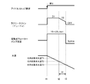
- FIG. 6 is a timing chart for explaining a third control operation of the water pump and the radiator fan during idle stop in the cooling control apparatus shown in FIG. 1.
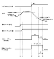
- FIG. 5 is a timing chart of each signal in a modification example of the first control operation shown in FIG. 2.
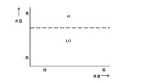
- FIG. It is a characteristic view which shows the relationship between the vehicle speed and water temperature of the modification of the 1st control action shown in FIG.
- FIG. 5 is a timing chart of each signal in a modified example of the second control operation shown in FIG. 4.
- FIG. 6 is a characteristic diagram illustrating a relationship between a vehicle speed and a water temperature in a modified example of the second control operation illustrated in FIG. 4. It is a characteristic view which shows the relationship between a water pump flow volume and a cylinder head flow velocity. It is a characteristic view for demonstrating the relationship between a water pump flow volume and a radiator fan drive voltage. It is a timing chart for demonstrating the cooling effect in the past and this invention.
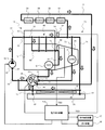
- FIG. 1 shows a configuration example of a cooling control apparatus for an internal combustion engine according to an embodiment of the present invention.
- a vehicle engine (internal combustion engine) 10 includes a cylinder head 11 and a cylinder block 12.
- a transmission 20 as an example of a power transmission device is connected to an output shaft of the engine 10, and an output of the transmission 20 is output. It is transmitted to drive wheels (not shown).
- the cooling device of the engine 10 is a water-cooled cooling device that circulates cooling water (cooling medium), and is a flow control valve 30 that is operated by an electric actuator, and an electric water pump (electric pump) that is driven by an electric motor. 40, a radiator 50, a radiator fan 53, a cooling water passage (cooling medium passage) 60 provided in the engine 10, a pipe 70 connecting them, and the like.
- a cooling water inlet 13 provided at one end of the cylinder head 11 in the cylinder arrangement direction and a cooling water outlet 14 provided at the other end of the cylinder head 11 in the cylinder arrangement direction are connected to the engine 10.
- a head-side cooling water passage 61 extending in the cylinder head 11 is provided.
- the engine 10 has a cooling water passage 60 that branches from the head side cooling water passage 61 to the cylinder block 12, extends into the cylinder block 12, and enters a cooling water outlet 15 provided in the cylinder block 12.
- a block-side cooling water passage 62 to be connected is provided.
- the coolant outlet 15 of the cylinder block 12 is provided at the same end in the cylinder arrangement direction as the side where the coolant outlet 14 is provided.
- the coolant is supplied to the cylinder block 12 via the cylinder head 11, and the coolant that has passed only the cylinder head 11 is discharged from the coolant outlet 14 and flows into the cylinder head 11 before the cylinder block 11.
- the cooling water that has passed through 12 is discharged from the cooling water outlet 15.
- One end of the first coolant pipe 71 is connected to the coolant outlet 14 of the cylinder head 11, and the other end of the first coolant pipe 71 is connected to the coolant inlet 51 of the radiator 50.
- One end of the second cooling water pipe 72 is connected to the cooling water outlet 15 of the cylinder block 12, and the other end of the second cooling water pipe 72 is the four inlet ports 31 to 34 (inflow side) of the flow control valve 30. Are connected to the first inlet port 31.
- An oil cooler (O / C) 16 for cooling the lubricating oil of the engine 10 is provided in the middle of the second cooling water pipe 72, and the oil cooler 16 is a cooling water flowing through the second cooling water pipe 72. Between the engine and the lubricating oil of the engine 10.
- the third cooling water pipe 73 has one end connected to the first cooling water pipe 71 and the other end connected to the second inlet port 32 of the flow control valve 30.
- the third cooling water pipe 73 is provided with an oil warmer (O / W) 21 for heating the hydraulic oil of the transmission 20 in the middle.
- the oil warmer 21 exchanges heat between the coolant flowing in the third coolant pipe 73 and the hydraulic oil of the transmission 20. That is, the coolant that has passed through the cylinder head 11 is diverted and guided to the water-cooled oil warmer 21, and the hydraulic oil is heated in the oil warmer 21.
- the fourth cooling water pipe 74 has one end connected to the first cooling water pipe 71 and the other end connected to the third inlet port 33 of the flow control valve 30.
- Various heat exchange devices are provided in the fourth cooling water pipe 74.
- a heater core 91 for heating the vehicle, a water-cooled EGR cooler (ERG / C) 92 that constitutes the exhaust gas recirculation device of the engine 10, and the exhaust gas recirculation device are also constructed in this order from the upstream side.
- An exhaust gas recirculation control valve (EGR / V) 93 for adjusting the exhaust gas recirculation amount and a throttle valve 94 for adjusting the intake air amount of the engine 10 are provided.
- the heater core 91 is a device that heats the conditioned air by exchanging heat between the cooling water in the fourth cooling water pipe 74 and the conditioned air.
- the EGR cooler 92 is a device that causes heat exchange between the exhaust gas recirculated to the intake system of the engine 10 by the exhaust gas recirculation device and the cooling water in the fourth cooling water pipe 74 to lower the temperature of the recirculated exhaust gas. It is. Further, the exhaust gas recirculation control valve 93 and the throttle valve 94 are configured to be heated by exchanging heat with the cooling water in the fourth cooling water pipe 74. As a result, the moisture contained in the exhaust and intake air is prevented from freezing around the exhaust gas recirculation control valve 93 and the throttle valve 94.
- the fifth cooling water pipe 75 has one end connected to the cooling water outlet 52 of the radiator 50 and the other end connected to the fourth inlet port 34 of the flow control valve 30.
- the flow control valve 30 has one outlet port 35, and one end of a sixth cooling water pipe 76 is connected to the outlet port 35.
- the other end of the sixth cooling water pipe 76 is connected to the suction port 41 of the water pump 40.
- One end of a seventh cooling water pipe 77 is connected to the discharge port 42 of the water pump 40, and the other end of the seventh cooling water pipe 77 is connected to the cooling water inlet 13 of the cylinder head 11.
- the flow control valve 30 includes four inlet ports 31 to 34 and one outlet port 35, and cooling water pipes 72, 73, 74, and 75 are connected to the inlet ports 31 to 34, respectively.
- a sixth cooling water pipe 76 is connected to the outlet port 35.
- the flow control valve 30 is, for example, a rotary flow path switching valve, and a rotor provided with a flow path is fitted into a stator in which a plurality of ports 31 to 35 are formed, and the rotor is an electric actuator such as an electric motor.
- the rotor is rotationally driven to change the angular position of the rotor, thereby connecting the openings of the stator.
- the opening area ratio of the four inlet ports 31 to 34 changes according to the rotor angle, and the desired opening area ratio (flow rate ratio) can be controlled by selecting the rotor angle.
- the rotor flow path and the like are adapted.
- the head-side cooling water passage 61 and the first cooling water pipe 71 constitute a first cooling liquid line that passes through the cylinder head 11 and the radiator 50
- the block-side cooling water passage 62 and the second cooling water pipe. 72 constitutes a second coolant line that bypasses the radiator 50 via the cylinder block 12.
- the head-side cooling water passage 61 and the fourth cooling water pipe 74 constitute a third cooling liquid line that bypasses the radiator 50 via the cylinder head 11 and the heater core 91.
- the head-side cooling water passage 61 and the third cooling water pipe 73 constitute a fourth coolant line that bypasses the radiator 50 via the cylinder head 11 and the oil warmer 21 of the transmission 20.
- the eighth cooling water pipe 78 forms a bypass line that branches from the first coolant line between the cylinder head 11 and the radiator 50, bypasses the radiator 50, and joins to the outflow side of the flow control valve 30.
- the flow rate control valve 30 has the above-described first coolant line, second coolant line, third coolant line, and fourth coolant line connected to the inflow side, and the outflow side is the suction side of the water pump 40. Connected to.
- This flow control valve 30 adjusts the outlet opening area of each cooling liquid line, thereby supplying cooling water to the first cooling liquid line, the second cooling liquid line, the third cooling liquid line, and the fourth cooling liquid line.
- This is a flow path switching mechanism that controls the amount (distribution ratio).
- the flow control valve 30 includes a plurality of flow path switching patterns, and is configured to be switched to one of these flow path switching patterns by changing the rotor angle with an electric actuator. That is, the flow control valve 30 closes all the inlet ports 31 to 34 within a predetermined angle range from the reference angular position where the rotor angle is regulated by the stopper.
- the state where all the inlet ports 31 to 34 are closed includes a state where the opening area of each of the inlet ports 31 to 34 is zero and a state where the minimum opening area is larger than zero (a state where a leakage flow rate is generated). Shall be included.
- the third inlet port 33 to which the outlet of the heater core coolant line is connected opens to a certain degree of opening, and thereafter the rotor angle
- the constant flow rate is maintained with respect to the increase of.
- the first inlet port 31 to which the outlet of the block coolant line is connected opens, and the opening area of the first inlet port 31 is It gradually increases as the rotor angle increases.
- the second inlet port 32 to which the outlet of the power transmission system coolant line is connected is opened to a certain degree of opening at an angular position larger than the angle at which the first inlet port 31 opens, and then the rotor angle increases. To maintain the constant opening. Furthermore, the fourth inlet port 34 to which the outlet of the radiator coolant line is connected opens at an angular position larger than the angle at which the second inlet port 32 opens to a certain opening, and the opening area of the fourth inlet port 34 is: It increases gradually as the rotor angle increases.
- a water temperature sensor (first temperature sensor) 81 that detects the temperature of the cooling water in the first cooling water pipe 71, that is, the temperature of the cooling water near the outlet of the cylinder head 11, is provided in the vicinity of the cooling water outlet 14.
- the water temperature detection signal TW1 of the water temperature sensor 81 is input to an electronic control device (controller, control unit) 100 including a microcomputer. Then, the electronic control unit 100 outputs operation signals to the water pump 40 and the flow rate control valve 30 to control the discharge amount of the water pump 40 and the flow rate ratio by the flow rate control valve 30.
- the water temperature sensor may be only the water temperature sensor 81 that detects the temperature of the cooling water near the outlet of the cylinder head 11, but in this example, the temperature of the cooling water in the second cooling water pipe 72 near the cooling water outlet 15 is further detected.
- a water temperature sensor (second temperature sensor) 82 is also provided.
- the water temperature detection signal TW2 of the water temperature sensor 82 is input to the electronic control unit 100, and the discharge rate of the water pump 40 and the flow rate ratio by the flow control valve 30 are controlled in consideration of the water temperature detection signal TW2 in addition to the water temperature detection signal TW1. It is like that.
- the temperature of the cylinder block 12 can be controlled and the friction of the engine 10 can be reduced, thereby improving the fuel consumption. Can do.
- the electronic control device 100 has a function of controlling the fuel injection device 17 and the ignition device 18 of the engine 10, and has an idle stop control function of temporarily stopping the engine 10 when waiting for a vehicle signal.
- An electronic control device having a control function of the engine 10 is provided separately from the electronic control device 100, and the electronic control device 100 for engine control, the cooling system electronic control device 100 for controlling the water pump 40 and the flow control valve 30 is provided. Can be configured to communicate with each other.
- the electronic control unit 100 sequentially switches the rotor angle (flow path switching pattern) of the flow control valve 30 as the engine 10 warms up, and discharges water from the water pump 40 and cooling air from the radiator fan 53. It has a function to change.
- the temperature of the cylinder head 11 and the temperature of the cylinder block 12 are controlled to their respective targets.
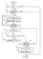
- FIG. 2 shows a first control operation during idle stop.
- IS idle stop
- the cooling water temperature (water temperature) detected by the water temperature sensor is the idle stop cooling request water temperature (IS)
- T1 the idle stop cooling request water temperature
- a first temperature sensor 81 for detecting the temperature of the coolant having a large temperature change near the outlet of the cylinder head 11 may be used.
- the outlet of the cylinder block 12 may be used.
- step S2 If it is determined in step S2 that the coolant temperature detected by the temperature sensors 81 and 82 is higher than or equal to the IS cooling request water temperature T1, the radiator fan 53 is driven at high speed (HI) (step S3). Further, the electric water pump (WP) 40 is driven so as to discharge the cooling water at a flow rate 15 to 25 (first predetermined flow rate) smaller than the discharge amount required in the idling operation of the internal combustion engine (step S4). . On the other hand, when it is determined that the cooling water temperature detected by the temperature sensors 81 and 82 is lower than the IS cooling request water temperature T1, the cooling is unnecessary and the process is terminated.
- HI high speed
- step S5 it is determined whether or not the water temperature is lower than the IS cooling required water temperature T2 (T2 ⁇ T1) (step S5). If it is determined to be low, the radiator fan 53 is switched to low speed (LO) drive (step S6). If it is determined that it is higher or equal, the process returns to step S3 to drive the radiator fan 53 at a high speed and drive the water pump 40 to discharge cooling water at a flow rate of 15 to 25 L / min for cooling.
- T2 ⁇ T1 the IS cooling required water temperature
- step S7 it is determined whether or not the water temperature has risen. If it is determined that the water temperature has risen, the radiator fan 53 is driven at a high speed for a predetermined time (step S8). If it is determined in step S7 that the water temperature has not risen, it is determined whether or not the water temperature is lower than the IS cooling request water temperature T3 (T3 ⁇ T2) (step S9). If it is determined that it is higher or equal, the radiator fan 53 is stopped (OFF) (step S10), and the water pump 40 is driven to discharge cooling water at a flow rate of 3 L / min (second predetermined flow rate). Cooling is performed (step S11). At this time, the discharge flow rate of the water pump 40 is set larger than the minimum dischargeable flow rate. If it is determined in step S9 that the water temperature is lower than the IS cooling request water temperature T3, the process returns to step S6 and the operations of steps S6 to S9 are repeated.
- the radiator fan 53 is driven at a high speed, and the water pump 40 is driven to discharge cooling water at a flow rate of 15 to 25 L / min.
- the radiator fan 53 is switched to low speed driving.
- the radiator fan 53 is stopped (OFF) and the water pump 40 is switched to drive for discharging cooling water at a flow rate of 3 L / min. If the water temperature rises between time t2 and time t3 ( ⁇ t), the radiator fan 53 is switched to high speed driving for a predetermined time.
- the water pump 40 (electric type) that consumes less power is used.
- the radiator fan 53 that consumes a large amount of power in a state where the pump) is operated and the cooling water (cooling medium) is circulated, the power consumption can be reduced while improving the cooling effect.
- the water pump 40 is continuously driven so as to discharge the cooling water with a low flow rate, so that the cooling water temperature rises due to the residual heat.
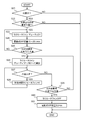
- FIG. 4 shows a second control operation of the water pump 40 and the radiator fan 53 during idle stop.
- IS idle stop
- the cooling water temperature detected by the temperature sensors 81 and 82 is the idle stop cooling required water temperature (IS)
- T1 the idle stop cooling required water temperature
- step S22 when it is determined that the cooling water temperature detected by the temperature sensors 81 and 82 is higher than or equal to the IS cooling request water temperature T1, the radiator fan 53 is driven with the duty D1 (step S23).
- the duty D1 is set to be large in order to drive the radiator fan 53 at high speed.
- the water pump 40 is driven so as to discharge the cooling water at a flow rate of 15 to 25 L / min (step S24).
- the cooling is unnecessary and the process is terminated.
- step S25 it is determined whether or not the water temperature is lower than the IS cooling required water temperature T2 (T2 ⁇ T1) (step S25). If it is determined to be low, the radiator fan 53 is decelerated toward the duty D2 (step S26). If it is determined that it is higher or equal, the process returns to step S23 to drive at high speed with the duty D1 of the radiator fan 53 and to cool the water pump 40 by discharging cooling water at a flow rate of 15 to 25 L / min. I do.
- step S27 it is determined whether or not the water temperature has risen. If it is determined that the water temperature has risen, the radiator fan is driven at a high speed for a predetermined time (step S28). If it is determined in step S27 that the water temperature has not risen, it is determined whether the water temperature is lower than the IS cooling request water temperature T3 (T3 ⁇ T2) (step S29). If it is determined to be higher or equal, the radiator fan 53 is stopped (step S30), and the water pump 40 is driven to discharge cooling water at a flow rate of 3 L / min for cooling (step S31). If it is determined in step S29 that the water temperature is lower than the IS cooling request water temperature T3, the process returns to step S26 and the operations in steps S26 to S29 are repeated.
- the water pump 40 is continuously driven so as to discharge the cooling water with a low flow rate, so that the cooling water temperature is prevented from rising due to residual heat, and the cooling water is suppressed. It is possible to suppress a decrease in the temperature detection accuracy of the water temperature sensor due to temperature variations in the pipe. As a result, excessive correction of the ignition timing at the time of engine restart can be reduced, and a reduction in torque and deterioration in fuel consumption can be suppressed. In addition, quietness can be improved by the early stop of the radiator fan during idle stop. Moreover, the pre-ignition at the time of high water temperature restart can also be suppressed.
- FIG. 6 shows a third control operation.
- the cooling control apparatus includes an electronic control thermostat
- the wax is energized to control the thermo-opening water temperature (control water temperature). ).
- the electronic control thermostat is energized under the control of the electronic control device 100, and then the lift amount of the electronic control thermostat increases (time t1). As a result, the thermo-opening water temperature decreases.
- the water temperature is higher than the IS cooling request water temperature T1, so that the radiator fan 53 is driven at high speed by the electronic control unit 100 and the water pump 40 is cooled at a flow rate of 15 to 25 L / min. Driven to discharge water.
- the radiator fan 53 When the water temperature becomes lower than the IS cooling request water temperature T2 at time t3, the radiator fan 53 is switched to low speed driving. When the water temperature becomes lower than the IS cooling request water temperature T3 at time t4, the radiator fan 53 is stopped (OFF), and the water pump 40 is switched to drive so as to discharge the cooling water at a flow rate of 3 L / min.
- the third control operation in addition to the water pump 40 and the radiator fan 53, by controlling the valve opening water temperature of the electronically controlled thermostat, the cooling effect is improved more than the first and second control operations. Power consumption can be reduced.
- FIG. 7a shows a modification of the first control operation shown in FIG.
- the first modification not only performs drive control of the water pump 40 and the radiator fan 53 at the time of idling stop, but also performs pre-cooling in preparation for re-acceleration after idling stop at the time of vehicle deceleration. Is what you do.
- the throttle is closed at time t5
- the radiator fan 53 is driven at a high speed and the water pump 40 discharges the cooling water at a flow rate of 15 to 25 L / min. Driven.
- the control of the radiator fan 53 at this time is determined according to the water temperature and the vehicle speed. For example, as shown by a broken line in FIG. 7b, the radiator fan 53 is driven at a high speed if the water temperature is higher than a predetermined value, and is driven at a low speed if low.
- the radiator fan 53 When the water temperature becomes lower than the IS cooling required water temperature T6 at time t6 (T6 ⁇ T5), the radiator fan 53 is switched to low speed driving. At time t7, when the throttle is opened, the flow rate of the water pump 40 is increased and the water temperature starts to rise.
- power consumption can be reduced while improving the cooling effect by performing pre-cooling in preparation for re-acceleration after idle stop. That is, when the radiator fan 53 is stopped while the vehicle is running before the idle stop, the cooling fan after the idle stop is shortened by starting the operation of the radiator fan after the vehicle is decelerated until it stops. And pre-ignition at the time of early automatic start can be suppressed. In addition, the operation time of the radiator fan during idle stop can be shortened, and quietness can be improved.
- FIG. 8a shows a modification of the second control operation shown in FIG.
- the second modification not only performs drive control of the water pump 40 and the radiator fan 53 at the time of idling stop, but also performs pre-cooling in preparation for re-acceleration after idling stop at the time of vehicle deceleration. Is what you do.
- the throttle is closed at time t5
- the radiator fan 53 is driven with the duty D2 and the water pump 40 discharges the cooling water at a flow rate of 15 to 25 L / min. Driven by.
- the control of the radiator fan 53 at this time is determined according to the water temperature and the vehicle speed. For example, as shown by the broken line in FIG. 8b, when the duty is large (duty is large), the water temperature is determined regardless of the vehicle speed, and the duty is small. In (DUTY small), the water temperature increases as the vehicle speed increases.
- the radiator fan 53 is switched to drive at the duty D1.
- the flow rate of the water pump 40 is increased and the water temperature starts to rise. According to such a control method, power consumption can be reduced while improving the cooling effect by performing pre-cooling in preparation for re-acceleration after idle stop.
- FIG. 9 shows the relationship between the water pump flow rate and the cylinder head flow velocity.
- the flow rate and the flow velocity are basically in a proportional relationship, it is known that the heat dissipation effect is slowed even if the flow velocity is increased. Specifically, it is said that the heat dissipation effect slows down when the flow velocity is 0.7 m / sec or more. Therefore, in the above-described embodiment, as shown by the broken line, the water pump flow rate (15 to 25 L / min) when the flow velocity is 0.7 m / sec is experimentally obtained, and the water pump 40 is set to this flow rate during idling stop. did.
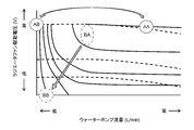
- FIG. 10 shows the relationship between the water pump flow rate and the radiator fan drive voltage in the present invention.
- the solid line shows the change in the water temperature after 60 seconds from the idle stop, and is the change when the initial temperature is different.
- the broken line has shown the change of the sum of the power consumption of the radiator fan 53 and the water pump 40.
- FIG. 10 Even if the flow rate of the water pump 40 is increased as shown in a region AA surrounded by a broken line, the cooling effect does not change much, and only the power consumption increases. Moreover, even if the water pump 40 is stopped as shown in the area AB after the water temperature is lowered, the reduction in power consumption is small.
- the flow rate of the water pump 40 is set as shown in the area BA surrounded by the alternate long and short dash line, and then the radiator fan is stopped. As shown in the area BA, the flow rate of the water pump 40 is reduced, and the driving voltage of the radiator fan 53 is lowered to reduce the power consumption. Further, as shown in the timing chart of FIG. 11, the ignition timing can be advanced by cooling even during idling stop, and fuel efficiency can be improved also in this respect. For example, it is assumed that the accelerator is closed at time t11, the idle stop is performed between times t12 and t13, and the accelerator operation is performed from time t13.
- the change in the cooling water temperature at this time is maintained as a high temperature state as indicated by a broken line when it is not cooled, but decreases as indicated by a solid line due to cooling by the radiator fan 53 and the water pump 40. This corrects the ignition timing to advance, increasing the torque and improving the fuel efficiency.
- the present invention is not limited to such a system configuration.
- Any cooling control device for an internal combustion engine including an electric pump that circulates the cooling medium in a cooling medium passage formed in the internal combustion engine, a radiator that cools the cooling medium, and a radiator fan can be applied.
- the case where the first temperature sensor 81 detects the temperature of the cooling water near the outlet of the cylinder head 11 and the second temperature sensor 82 detects the temperature of the cooling water near the outlet of the cylinder block 12 has been described as an example. As long as the temperature of the cooling water can be detected, it may be provided elsewhere. Furthermore, although the cooling apparatus provided with the flow control valve 30 operated by the electric actuator has been described as an example, the cooling apparatus can be applied to other structures as long as it is a water cooling type cooling apparatus.
- SYMBOLS 10 ... Engine (internal combustion engine), 20 ... Transmission, 30 ... Flow control valve, 40 ... Water pump (electric pump), 50 ... Radiator, 53 ... Radiator fan, 60 ... Cooling water passage (cooling medium passage), 81 , 82 ... temperature sensor (water temperature sensor), 100 ... electronic control unit
Landscapes
- Engineering & Computer Science (AREA)
- Chemical & Material Sciences (AREA)
- Combustion & Propulsion (AREA)
- Mechanical Engineering (AREA)
- General Engineering & Computer Science (AREA)
- Combined Controls Of Internal Combustion Engines (AREA)
- Control Of Vehicle Engines Or Engines For Specific Uses (AREA)
Abstract
本発明は、電動式ポンプにより冷却水を循環させ、且つ電動ファンでラジエータへ冷却風を供給して内燃機関を冷却するための制御を行う冷却制御装置に関する。この冷却制御装置は、内燃機関に形成された冷却媒体通路に冷却媒体を循環させる電動式ポンプと、冷却媒体を冷却するラジエータ及びラジエータファンと、を備える。内燃機関が暖機完了後に停止するときに、ラジエータファンと電動式ポンプを駆動して内燃機関を冷却し、冷却媒体の温度が、機関停止したときよりも低下した場合に、電動式ポンプが作動している状態で、ラジエータファンを停止させる。
Description
本発明は、電動式ポンプにより冷却水を循環させ、且つ電動ファンでラジエータへ冷却風を供給して内燃機関を冷却するための制御を行う冷却制御装置及びその冷却制御方法に関する。
内燃機関(エンジン)の冷却性能は外気温の影響を受けるので、特許文献1では、エンジンの停止後に、冷却水の温度及びバッテリの電圧に加え、外気温の違いを加味して電動ポンプと電動ファンを制御している。この特許文献1では、イグニションスイッチがオフになると、電動式ポンプと電動ファンを作動させ、電動式ポンプを停止させた後に電動ファンを停止させる。
しかしながら、上記特許文献1の技術は、アイドルストップからの再始動時の水温センサの検出誤差や、水温センサの温度変化に対する検出応答の遅れについては考慮していない。このため、冷却効果の向上と電力消費の低減を両立させる、という観点からはまだ改良の余地がある。すなわち、水温センサは、配管内の温度ばらつきなどにより、冷却水が流動していないと正確な水温が測れないため、エンジン停止中に電動式ポンプを停止させると再始動時に検出誤差が大きくなる。また、シリンダヘッド部の温度変化の時定数は、水温センサの検知温度に対して3倍程度も速いため、エンジン停止による温度低下に対して水温センサの検出応答が遅れる。この結果、エンジンが再始動されたときに、ノック回避のために点火時期が遅角方向に過剰補正され、トルクが低下したり燃費が悪化したりする。
本発明は上記のような事情に鑑みてなされたもので、その目的とするところは、冷却効果を向上しつつ電力消費の低減が図れる内燃機関の冷却制御装置及びその冷却制御方法を提供することにある。
そのため、本発明の内燃機関の冷却制御装置は、内燃機関に形成された冷却媒体通路に冷却媒体を循環させる電動式ポンプと、前記冷却媒体を冷却するラジエータ及びラジエータファンと、を備え、前記内燃機関が暖機完了後に停止するときに、前記ラジエータファンと前記電動式ポンプを駆動して前記内燃機関を冷却し、前記冷却媒体の温度が、機関停止したときよりも低下した場合に、前記電動式ポンプが作動している状態で、前記ラジエータファンを停止させる。
また、本発明の内燃機関の冷却制御方法は、内燃機関に形成された冷却媒体通路に冷却媒体を循環させる電動式ポンプと、前記冷却媒体を冷却するラジエータ及びラジエータファンと、を備えた内燃機関の冷却制御方法であって、前記内燃機関が暖機完了後に停止したときに、前記ラジエータファンと前記電動式ポンプを駆動して前記内燃機関を冷却することと、前記冷却媒体の温度が、機関停止したときよりも低下した場合に、前記電動式ポンプが作動している状態で、前記ラジエータファンを停止させること、とを具備する。
また、本発明の内燃機関の冷却制御方法は、内燃機関に形成された冷却媒体通路に冷却媒体を循環させる電動式ポンプと、前記冷却媒体を冷却するラジエータ及びラジエータファンと、を備えた内燃機関の冷却制御方法であって、前記内燃機関が暖機完了後に停止したときに、前記ラジエータファンと前記電動式ポンプを駆動して前記内燃機関を冷却することと、前記冷却媒体の温度が、機関停止したときよりも低下した場合に、前記電動式ポンプが作動している状態で、前記ラジエータファンを停止させること、とを具備する。
本発明によれば、内燃機関が暖機完了後に停止するときに、ラジエータファンと電動式ポンプを駆動することで冷却効果を向上させることができる。また、冷却媒体の温度が機関停止するときよりも低下したときに、電力消費の少ない電動式ポンプを作動させて冷却媒体を循環させた状態で、電力消費の大きいラジエータファンを停止させることで電力消費の低減が図れる。しかも、電動式ポンプを駆動し続けることで、水温センサの温度検出精度の低下を抑制できると共に、冷却水を循環させ続けることで、温度変化の時定数の違いの影響を抑制できる。これによって、機関再始動時の点火時期の過剰補正を軽減し、トルクの低下や燃費の悪化を抑制できる。
以下、本発明の実施形態について図面を参照して説明する。
図1は、本発明の実施形態に係る内燃機関の冷却制御装置の構成例を示している。車両用のエンジン(内燃機関)10は、シリンダヘッド11及びシリンダブロック12を有し、エンジン10の出力軸には、動力伝達装置の一例としての変速機20が接続され、変速機20の出力が図示しない駆動輪に伝達される。
エンジン10の冷却装置は、冷却水(冷却媒体)を循環させる水冷式冷却装置であり、電気式アクチュエータによって動作する流量制御弁30、電動モータで駆動される電動式のウォーターポンプ(電動式ポンプ)40、ラジエータ50、ラジエータファン53、エンジン10に設けた冷却水通路(冷却媒体通路)60、これらを接続する配管70などで構成される。
エンジン10には、冷却水通路60として、シリンダヘッド11の気筒配列方向の一方端に設けた冷却水入口13と、シリンダヘッド11の気筒配列方向の他方端に設けた冷却水出口14とを接続し、シリンダヘッド11内に延設されるヘッド側冷却水通路61を設けている。
また、エンジン10には、冷却水通路60として、ヘッド側冷却水通路61から分岐してシリンダブロック12に至り、シリンダブロック12内に延設されて、シリンダブロック12に設けた冷却水出口15に接続されるブロック側冷却水通路62を設けている。シリンダブロック12の冷却水出口15は、冷却水出口14が設けられる側と同じ気筒配列方向の端部に設けられる。
また、エンジン10には、冷却水通路60として、ヘッド側冷却水通路61から分岐してシリンダブロック12に至り、シリンダブロック12内に延設されて、シリンダブロック12に設けた冷却水出口15に接続されるブロック側冷却水通路62を設けている。シリンダブロック12の冷却水出口15は、冷却水出口14が設けられる側と同じ気筒配列方向の端部に設けられる。
このように、シリンダブロック12には、シリンダヘッド11を経由して冷却水が供給され、シリンダヘッド11のみを通過した冷却水は冷却水出口14から排出され、シリンダヘッド11に流入した後シリンダブロック12内を通過した冷却水は冷却水出口15から排出される。
シリンダヘッド11の冷却水出口14には、第1冷却水配管71の一端が接続され、第1冷却水配管71の他端は、ラジエータ50の冷却水入口51に接続される。
シリンダヘッド11の冷却水出口14には、第1冷却水配管71の一端が接続され、第1冷却水配管71の他端は、ラジエータ50の冷却水入口51に接続される。
シリンダブロック12の冷却水出口15には、第2冷却水配管72の一端が接続され、第2冷却水配管72の他端は、流量制御弁30の4つの入口ポート31~34(流入側)のうちの第1入口ポート31に接続される。
第2冷却水配管72の途中には、エンジン10の潤滑油を冷却するためのオイルクーラー(O/C)16を設けてあり、オイルクーラー16は、第2冷却水配管72内を流れる冷却水とエンジン10の潤滑油との間で熱交換を行う。
第2冷却水配管72の途中には、エンジン10の潤滑油を冷却するためのオイルクーラー(O/C)16を設けてあり、オイルクーラー16は、第2冷却水配管72内を流れる冷却水とエンジン10の潤滑油との間で熱交換を行う。
また、第3冷却水配管73は、一端が第1冷却水配管71に接続され、他端が流量制御弁30の第2入口ポート32に接続される。この第3冷却水配管73は途中には、変速機20の作動油を加熱するためのオイルウォーマー(O/W)21が設けられる。
オイルウォーマー21は、第3冷却水配管73内を流れる冷却水と変速機20の作動油との間で熱交換を行う。つまり、シリンダヘッド11を通過した冷却水を分流させて水冷式のオイルウォーマー21に導き、オイルウォーマー21において作動油を加熱させる。
オイルウォーマー21は、第3冷却水配管73内を流れる冷却水と変速機20の作動油との間で熱交換を行う。つまり、シリンダヘッド11を通過した冷却水を分流させて水冷式のオイルウォーマー21に導き、オイルウォーマー21において作動油を加熱させる。
更に、第4冷却水配管74は、一端が第1冷却水配管71に接続され、他端が流量制御弁30の第3入口ポート33に接続される。
第4冷却水配管74には、各種の熱交換デバイスが設けられている。
第4冷却水配管74には、各種の熱交換デバイスが設けられている。
上記の熱交換デバイスとして、上流側から順に、車両暖房用のヒータコア(Heater)91、エンジン10の排気還流装置を構成する水冷式のEGRクーラ(ERG/C)92、同じく排気還流装置を構成する排気還流量を調整するための排気還流制御弁(EGR/V)93、及びエンジン10の吸入空気量を調整するスロットルバルブ(Throttle)94が設けられている。
ヒータコア91は、第4冷却水配管74内の冷却水と空調空気との間で熱交換を行わせ、空調空気を暖めるデバイスである。
ヒータコア91は、第4冷却水配管74内の冷却水と空調空気との間で熱交換を行わせ、空調空気を暖めるデバイスである。
EGRクーラ92は、排気還流装置によってエンジン10の吸気系に還流される排気と第4冷却水配管74内の冷却水との間で熱交換を行わせ、還流される排気の温度を低下させるデバイスである。
また、排気還流制御弁93及びスロットルバルブ94は、第4冷却水配管74内の冷却水との間で熱交換を行うことで暖められるように構成される。これにより排気中や吸気中に含まれる水分が、排気還流制御弁93、スロットルバルブ94の周辺で凍結することを抑制する。
また、排気還流制御弁93及びスロットルバルブ94は、第4冷却水配管74内の冷却水との間で熱交換を行うことで暖められるように構成される。これにより排気中や吸気中に含まれる水分が、排気還流制御弁93、スロットルバルブ94の周辺で凍結することを抑制する。
このように、シリンダヘッド11を通過した冷却水を分流させて、ヒータコア91、EGRクーラ92、排気還流制御弁93、及びスロットルバルブ94に導き、これらとの間での熱交換を行わせる。
また、第5冷却水配管75は、一端がラジエータ50の冷却水出口52に接続され、他端が流量制御弁30の第4入口ポート34に接続される。
また、第5冷却水配管75は、一端がラジエータ50の冷却水出口52に接続され、他端が流量制御弁30の第4入口ポート34に接続される。
流量制御弁30は、1つの出口ポート35を有し、この出口ポート35には、第6冷却水配管76の一端が接続される。第6冷却水配管76の他端は、ウォーターポンプ40の吸込口41に接続される。
そして、ウォーターポンプ40の吐出口42には第7冷却水配管77の一端が接続され、第7冷却水配管77の他端は、シリンダヘッド11の冷却水入口13に接続される。
そして、ウォーターポンプ40の吐出口42には第7冷却水配管77の一端が接続され、第7冷却水配管77の他端は、シリンダヘッド11の冷却水入口13に接続される。
また、第3冷却水配管73、第4冷却水配管74が接続される部分よりも下流側の第1冷却水配管71に一端が接続され、他端が第6冷却水配管76に接続される第8冷却水配管78を設けている。
流量制御弁30は、前述したように、4つの入口ポート31~34と1つの出口ポート35とを備え、入口ポート31~34には冷却水配管72,73,74,75がそれぞれ接続され、出口ポート35に第6冷却水配管76が接続される。
流量制御弁30は、前述したように、4つの入口ポート31~34と1つの出口ポート35とを備え、入口ポート31~34には冷却水配管72,73,74,75がそれぞれ接続され、出口ポート35に第6冷却水配管76が接続される。
流量制御弁30は、例えば回転式の流路切換バルブであり、複数のポート31~35が形成されたステータに、流路が設けられたロータを嵌装し、ロータを電動モータなどの電動アクチュエータで回転駆動してロータの角度位置を変更することで、ステータの各開口を接続する構成である。
そして、係る回転式の流量制御弁30では、ロータ角度に応じて4つの入口ポート31~34の開口面積割合が変化し、ロータ角度の選定によって所望の開口面積割合(流量割合)に制御できるようにロータの流路などが適合される。
そして、係る回転式の流量制御弁30では、ロータ角度に応じて4つの入口ポート31~34の開口面積割合が変化し、ロータ角度の選定によって所望の開口面積割合(流量割合)に制御できるようにロータの流路などが適合される。
上記構成において、ヘッド側冷却水通路61と第1冷却水配管71とによって、シリンダヘッド11及びラジエータ50を経由する第1冷却液ラインが構成され、ブロック側冷却水通路62と第2冷却水配管72とによって、シリンダブロック12を経由しラジエータ50を迂回する第2冷却液ラインが構成される。
また、ヘッド側冷却水通路61と第4冷却水配管74とによって、シリンダヘッド11及びヒータコア91を経由しラジエータ50を迂回する第3冷却液ラインが構成される。ヘッド側冷却水通路61と第3冷却水配管73とによって、シリンダヘッド11及び変速機20のオイルウォーマー21を経由しラジエータ50を迂回する第4冷却液ラインが構成される。
また、ヘッド側冷却水通路61と第4冷却水配管74とによって、シリンダヘッド11及びヒータコア91を経由しラジエータ50を迂回する第3冷却液ラインが構成される。ヘッド側冷却水通路61と第3冷却水配管73とによって、シリンダヘッド11及び変速機20のオイルウォーマー21を経由しラジエータ50を迂回する第4冷却液ラインが構成される。
更に、第8冷却水配管78によって、シリンダヘッド11とラジエータ50との間の第1冷却液ラインから分岐し、ラジエータ50を迂回して流量制御弁30の流出側に合流するバイパスラインが構成される。
つまり、流量制御弁30は、上述した第1冷却液ライン、第2冷却液ライン、第3冷却液ライン及び第4冷却液ラインがそれぞれ流入側に接続され、流出側はウォーターポンプ40の吸引側に接続される。この流量制御弁30は、各冷却液ラインの出口開口面積を調整することで、第1冷却液ライン、第2冷却液ライン、第3冷却液ライン及び第4冷却液ラインへの冷却水の供給量(分配割合)を制御する流路切り替え機構である。
つまり、流量制御弁30は、上述した第1冷却液ライン、第2冷却液ライン、第3冷却液ライン及び第4冷却液ラインがそれぞれ流入側に接続され、流出側はウォーターポンプ40の吸引側に接続される。この流量制御弁30は、各冷却液ラインの出口開口面積を調整することで、第1冷却液ライン、第2冷却液ライン、第3冷却液ライン及び第4冷却液ラインへの冷却水の供給量(分配割合)を制御する流路切り替え機構である。
流量制御弁30は、複数の流路切替えパターンを備え、電動アクチュエータでロータ角度を変更することで、これらの流路切替えパターンのいずれかに切り替わる構成になっている。
すなわち、流量制御弁30は、ロータ角度がストッパで規制される基準角度位置から所定角度範囲内では、入口ポート31~34を全て閉じる。
なお、これら入口ポート31~34を全て閉じる状態は、各入口ポート31~34の開口面積を零とする状態の他、零よりも大きい最小開口面積とする状態(漏れ流量が発生する状態)を含むものとする。
すなわち、流量制御弁30は、ロータ角度がストッパで規制される基準角度位置から所定角度範囲内では、入口ポート31~34を全て閉じる。
なお、これら入口ポート31~34を全て閉じる状態は、各入口ポート31~34の開口面積を零とする状態の他、零よりも大きい最小開口面積とする状態(漏れ流量が発生する状態)を含むものとする。
上記入口ポート31~34を全て閉じられる角度よりもロータ角度を増加させると、ヒータコア冷却液ラインの出口が接続される第3入口ポート33が一定開度にまで開くようになり、その後、ロータ角度の増大に対して前記一定の流量を保持する。
第3入口ポート33が一定開度にまで開く角度から更にロータ角度を増大させると、ブロック冷却液ラインの出口が接続される第1入口ポート31が開き出し、第1入口ポート31の開口面積は、ロータ角度の増大に応じて漸増する。
第3入口ポート33が一定開度にまで開く角度から更にロータ角度を増大させると、ブロック冷却液ラインの出口が接続される第1入口ポート31が開き出し、第1入口ポート31の開口面積は、ロータ角度の増大に応じて漸増する。
第1入口ポート31が開き出する角度よりもより大きな角度位置で、動力伝達系冷却液ラインの出口が接続される第2入口ポート32が一定開度まで開き、その後、ロータ角度の増大に対して前記一定開度を保持する。
更に、第2入口ポート32が一定開度まで開く角度よりも大きな角度位置で、ラジエータ冷却液ラインの出口が接続される第4入口ポート34が開き出し、第4入口ポート34の開口面積は、ロータ角度の増大に応じて漸増する。
更に、第2入口ポート32が一定開度まで開く角度よりも大きな角度位置で、ラジエータ冷却液ラインの出口が接続される第4入口ポート34が開き出し、第4入口ポート34の開口面積は、ロータ角度の増大に応じて漸増する。
冷却水出口14の近傍に、第1冷却水配管71内の冷却水温度、つまり、シリンダヘッド11の出口付近の冷却水の温度を検出する水温センサ(第1温度センサ)81を設けている。水温センサ81の水温検出信号TW1は、マイクロコンピュータを備える電子制御装置(コントローラ、制御ユニット)100に入力される。そして、電子制御装置100は、ウォーターポンプ40及び流量制御弁30に操作信号を出力して、ウォーターポンプ40の吐出量、流量制御弁30による流量割合を制御する。
水温センサは、シリンダヘッド11の出口付近の冷却水の温度を検出する水温センサ81のみでも良いが、本例では更に冷却水出口15近傍の第2冷却水配管72内の冷却水温度を検出する水温センサ(第2温度センサ)82も設けている。水温センサ82の水温検出信号TW2は、電子制御装置100に入力され、水温検出信号TW1に加えて水温検出信号TW2も考慮してウォーターポンプ40の吐出量、流量制御弁30による流量割合を制御するようになっている。
このように、シリンダブロック12の出口付近の冷却水の温度を検出する水温センサ82を設けることで、シリンダブロック12の温度コントロールが可能となり、エンジン10のフリクション低減を図れるため、燃費を向上することができる。
また、電子制御装置100は、エンジン10の燃料噴射装置17、点火装置18を制御する機能を有し、また、車両の信号待ちの場合などにエンジン10を一時的に停止させるアイドルストップ制御機能を有している。
なお、エンジン10の制御機能を有する電子制御装置を、電子制御装置100とは別に設け、機関制御用の電子制御装置と、ウォーターポンプ40及び流量制御弁30を制御する冷却系の電子制御装置100との間で相互通信が行われるよう構成することができる。
なお、エンジン10の制御機能を有する電子制御装置を、電子制御装置100とは別に設け、機関制御用の電子制御装置と、ウォーターポンプ40及び流量制御弁30を制御する冷却系の電子制御装置100との間で相互通信が行われるよう構成することができる。
更に、電子制御装置100は、エンジン10の暖機の進行に伴って、流量制御弁30のロータ角度(流路切替えパターン)を順次切替えると共に、ウォーターポンプ40の吐出量とラジエータファン53による冷却風を変化させる機能を有する。そして、シリンダヘッド11の温度とシリンダブロック12の温度とをそれぞれの目標に制御するようになっている。
次に、電子制御装置100によるウォーターポンプ40とラジエータファン53の制御について詳しく説明する。図2は、アイドルストップ時の第1の制御動作を示している。まず、アイドルストップ(IS)要求があるか否かを判定し(ステップS1)、アイドルストップ要求がある場合には、水温センサで検出した冷却水温度(水温)が、アイドルストップ冷却要求水温(IS冷却要求水温)T1より高いか等しいか否かを判定する(ステップS2)。水温センサには、シリンダヘッド11の出口付近の温度変化の大きい冷却水の温度を検出する第1温度センサ81を用いても良いし、この第1温度センサ81に加えて、シリンダブロック12の出口付近で冷却水の温度を検出する第2温度センサ82の検出温度を考慮しても良い。ここでは、温度センサ81,82を用いるものとして説明する。アイドルストップ要求がない場合には終了し、運転シーンやエンジン10の状態に応じた冷却動作を行う。
ステップS2において、温度センサ81,82で検出した冷却水温度が、IS冷却要求水温T1より高いか等しいと判定された場合には、ラジエータファン53を高速(HI)駆動する(ステップS3)。また、電動式ウォーターポンプ(WP)40を、内燃機関のアイドル運転で要求される吐出量よりも少ない流量15~25(第1所定流量)で冷却水を吐出するように駆動する(ステップS4)。
一方、温度センサ81,82で検出した冷却水温度が、IS冷却要求水温T1より低いと判定された場合には、冷却は不要であるので終了する。
一方、温度センサ81,82で検出した冷却水温度が、IS冷却要求水温T1より低いと判定された場合には、冷却は不要であるので終了する。
ステップS5では、水温がIS冷却要求水温T2(T2<T1)より低いか否かを判定する(ステップS5)。低いと判定された場合には、ラジエータファン53を低速(LO)駆動に切り換える(ステップS6)。高いか等しいと判定された場合には、ステップS3に戻ってラジエータファン53を高速駆動すると共に、ウォーターポンプ40を流量15~25L/minで冷却水を吐出するように駆動して冷却を行う。
次のステップS7で水温が上昇したか否かを判定し、上昇したと判定されると所定時間ラジエータファン53を高速駆動する(ステップS8)。ステップS7で水温が上昇していないと判定されると、水温がIS冷却要求水温T3(T3<T2)より低いか否かを判定する(ステップS9)。高いか等しいと判定された場合には、ラジエータファン53を停止(OFF)し(ステップS10)、ウォーターポンプ40を流量3L/min(第2所定流量)で冷却水を吐出するように駆動して冷却を行う(ステップS11)。この際、ウォーターポンプ40の吐出流量は、最低吐出可能流量よりも大きくする。ステップS9で水温がIS冷却要求水温T3より低いと判定された場合には、ステップS6に戻りステップS6~S9の動作を繰り返す。
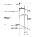
上述した第1の制御動作では、図3のタイミングチャートに示すように、時刻t1に、電子制御装置100からアイドルストップ要求が有り、この時の水温がIS冷却要求水温T1より高いと、ラジエータファン53が高速で駆動されると共に、ウォーターポンプ40が流量15~25L/minで冷却水を吐出するように駆動される。時刻t2に、水温がIS冷却要求水温T2より低くなると、ラジエータファン53が低速駆動に切り換えられる。そして、時刻t3に、水温がIS冷却要求水温T3より低くなると、ラジエータファン53が停止(OFF)されると共に、ウォーターポンプ40が流量3L/minで冷却水を吐出する駆動に切り換えられる。
なお、時刻t2~t3間(Δt)で水温が上昇する場合には、ラジエータファン53が所定時間高速駆動に切り換えられる。
なお、時刻t2~t3間(Δt)で水温が上昇する場合には、ラジエータファン53が所定時間高速駆動に切り換えられる。
上述した第1の制御動作によれば、冷却水(冷却媒体)がアイドルストップ(機関停止)するときよりも低いIS冷却要求水温T3まで低下したときに、電力消費の少ないウォーターポンプ40(電動式ポンプ)を作動させて冷却水(冷却媒体)を循環させた状態で、電力消費の大きいラジエータファン53を停止させることで、冷却効果を向上しつつ電力消費の低減が図れる。
しかも、エンジン(内燃機関)が暖機完了後にアイドルストップ(機関停止)するときに、ウォーターポンプ40を低流量の冷却水を吐出するように駆動し続けることで、残熱により冷却水温が上昇するのを抑制しつつ、冷却水の配管内の温度ばらつきによる水温センサの温度検出精度の低下を抑制できる。これらにより、エンジン再始動時の点火時期の過剰補正を軽減し、トルクの低下や燃費の悪化を抑制できる。
しかも、エンジン(内燃機関)が暖機完了後にアイドルストップ(機関停止)するときに、ウォーターポンプ40を低流量の冷却水を吐出するように駆動し続けることで、残熱により冷却水温が上昇するのを抑制しつつ、冷却水の配管内の温度ばらつきによる水温センサの温度検出精度の低下を抑制できる。これらにより、エンジン再始動時の点火時期の過剰補正を軽減し、トルクの低下や燃費の悪化を抑制できる。
加えて、アイドルストップ時のラジエータファンの早期停止による静粛性の向上も図れる。また、高水温再始動時のプレイグニッションも抑制できる。
なお、上記第1の制御動作では、ラジエータファンを3段切り換えする例を説明したが、更に段数を増やしてきめ細かな制御を行うようにしても良いのはもちろんである。
なお、上記第1の制御動作では、ラジエータファンを3段切り換えする例を説明したが、更に段数を増やしてきめ細かな制御を行うようにしても良いのはもちろんである。
図4は、アイドルストップ時のウォーターポンプ40とラジエータファン53の第2の制御動作を示している。まず、アイドルストップ(IS)要求があるか否かを判定し(ステップS21)、アイドルストップ要求がある場合には、温度センサ81,82で検出した冷却水温度が、アイドルストップ冷却要求水温(IS冷却要求水温)T1より高いか等しいか否かを判定する(ステップS22)。アイドルストップ要求がない場合には終了し、運転シーンやエンジン10の状態に応じた冷却動作を行う。
ステップS22において、温度センサ81,82で検出した冷却水温度が、IS冷却要求水温T1より高いか等しいと判定された場合には、ラジエータファン53をデューティD1で駆動する(ステップS23)。デューティD1は、ラジエータファン53を高速で駆動するためにデューティが大きく設定される。また、ウォーターポンプ40を流量15~25L/minで冷却水を吐出するように駆動する(ステップS24)。
一方、温度センサ81,82で検出した冷却水温度が、IS冷却要求水温T1より低いと判定された場合には、冷却は不要であるので終了する。
一方、温度センサ81,82で検出した冷却水温度が、IS冷却要求水温T1より低いと判定された場合には、冷却は不要であるので終了する。
ステップS25では、水温がIS冷却要求水温T2(T2<T1)より低いか否かを判定する(ステップS25)。低いと判定された場合には、ラジエータファン53をデューティD2に向かって減速する(ステップS26)。高いか等しいと判定された場合には、ステップS23に戻ってラジエータファン53のデューティD1で高速駆動すると共に、ウォーターポンプ40を流量15~25L/minで冷却水を吐出するように駆動して冷却を行う。
次のステップS27で水温が上昇したか否かを判定し、上昇したと判定されると所定時間ラジエータファンを高速駆動する(ステップS28)。ステップS27で水温が上昇していないと判定されると、水温がIS冷却要求水温T3(T3<T2)より低いか否かを判定する(ステップS29)。高いか等しいと判定された場合には、ラジエータファン53を停止し(ステップS30)、ウォーターポンプ40を流量3L/minで冷却水を吐出するように駆動して冷却を行う(ステップS31)。ステップS29で水温がIS冷却要求水温T3より低いと判定された場合には、ステップS26に戻りステップS26~S29の動作を繰り返す。
上述した第2の制御動作では、図5のタイミングチャートに示すように、時刻t1に、電子制御装置100からアイドルストップ要求が有り、この時の水温がIS冷却要求水温T1より高いと、ラジエータファン53が第1のデューティD1で駆動されると共に、ウォーターポンプ40が流量15~25L/minで冷却水を吐出するように駆動される。時刻t2に、水温がIS冷却要求水温T2より低くなると、ラジエータファン53を駆動する信号のデューティが第2のデューティD2に切り換えられる。そして、時刻t3に、水温がIS冷却要求水温T3より低くなると、ラジエータファン53が停止されると共に、ウォーターポンプ40が流量3L/minで冷却水を吐出する駆動に切り換えられる。
なお、時刻t2~t3間(Δt)で水温が上昇する場合には、ラジエータファン53を駆動する信号のデューティD2を所定時間大きくする。
なお、時刻t2~t3間(Δt)で水温が上昇する場合には、ラジエータファン53を駆動する信号のデューティD2を所定時間大きくする。
上述した第2の制御動作であっても、基本的には第1の制御動作と同様な作用効果が得られる。すなわち、冷却水がアイドルストップするときよりも低いIS冷却要求水温T3まで低下したときに、電力消費の少ない電動式のウォーターポンプ40を作動させて冷却水を循環させた状態で、電力消費の大きいラジエータファン53を停止させることで、冷却効果を向上しつつ電力消費の低減が図れる。
また、エンジンが暖機完了後にアイドルストップするときに、ウォーターポンプ40を低流量の冷却水を吐出するように駆動し続けることで、残熱により冷却水温が上昇するのを抑制しつつ、冷却水の配管内の温度ばらつきによる水温センサの温度検出精度の低下を抑制できる。これらにより、エンジン再始動時の点火時期の過剰補正を軽減し、トルクの低下や燃費の悪化を抑制できる。
加えて、アイドルストップ時のラジエータファンの早期停止による静粛性の向上も図れる。また、高水温再始動時のプレイグニッションも抑制できる。
加えて、アイドルストップ時のラジエータファンの早期停止による静粛性の向上も図れる。また、高水温再始動時のプレイグニッションも抑制できる。
図6は、第3の制御動作を示しており、冷却制御装置が電子制御サーモスタットを備えている場合に、アイドルストップ状態で冷却要求があると、ワックスに通電してサーモ開弁水温(制御水温)を下げるものである。水温がIS冷却要求サーモ開弁水温に到達すると(時刻t0)、電子制御装置100の制御により電子制御サーモスタットに通電され、その後電子制御サーモスタットのリフト量が増大する(時刻t1)。これによって、サーモ開弁水温が低下する。時刻t2にアイドルストップ要求が有ると、水温がIS冷却要求水温T1よりも高いことから、電子制御装置100によりラジエータファン53が高速駆動されると共に、ウォーターポンプ40が流量15~25L/minで冷却水を吐出するように駆動される。
時刻t3に、水温がIS冷却要求水温T2より低くなると、ラジエータファン53が低速駆動に切り換えられる。そして、時刻t4に、水温がIS冷却要求水温T3より低くなると、ラジエータファン53が停止(OFF)されると共に、ウォーターポンプ40が流量3L/minで冷却水を吐出するように駆動に切り換えられる。
上記第3の制御動作によれば、ウォーターポンプ40とラジエータファン53に加えて、電子制御サーモスタットの開弁水温を制御することで、第1、第2の制御動作よりも冷却効果を向上しつつ電力消費の低減が図れる。
上記第3の制御動作によれば、ウォーターポンプ40とラジエータファン53に加えて、電子制御サーモスタットの開弁水温を制御することで、第1、第2の制御動作よりも冷却効果を向上しつつ電力消費の低減が図れる。
図7aは、図2に示した第1の制御動作の変形例を示している。本変形例1は、第1の制御動作と同様にアイドルストップ時にウォーターポンプ40とラジエータファン53の駆動制御を行うだけでなく、車両の減速時に、アイドルストップ後の再加速に備えた先行冷却を行うものである。時刻t5にスロットルが閉じられると、水温がIS冷却要求水温T5よりも高ければ、ラジエータファン53が高速で駆動されると共に、ウォーターポンプ40が流量15~25L/minで冷却水を吐出するように駆動される。このときのラジエータファン53の制御は水温と車速に応じて決定し、例えば図7bに破線で示すように、所定値よりも水温が高ければ高速回転、低ければ低速回転で駆動する。
時刻t6に、水温がIS冷却要求水温T6より低くなると(T6<T5)、ラジエータファン53が低速駆動に切り換えられる。そして、時刻t7に、スロットルが開くと、ウォーターポンプ40の流量が増大され、水温は上昇を始める。
このような制御方法によれば、アイドルストップ後の再加速に備えた先行冷却を行うことで、冷却効果を向上しつつ電力消費の低減が図れる。すなわち、アイドルストップ前の車両走行中にラジエータファン53が停止している場合に、車両が減速してから停止するまでにラジエータファンの作動を開始することで、アイドルストップ後の冷却期間を短縮することができ、早期自動始動時のプレイグニッションを抑制することができる。また、アイドルストップ中のラジエータファンの作動時間が短縮でき、静粛性も向上できる。
このような制御方法によれば、アイドルストップ後の再加速に備えた先行冷却を行うことで、冷却効果を向上しつつ電力消費の低減が図れる。すなわち、アイドルストップ前の車両走行中にラジエータファン53が停止している場合に、車両が減速してから停止するまでにラジエータファンの作動を開始することで、アイドルストップ後の冷却期間を短縮することができ、早期自動始動時のプレイグニッションを抑制することができる。また、アイドルストップ中のラジエータファンの作動時間が短縮でき、静粛性も向上できる。
図8aは、図4に示した第2の制御動作の変形例を示している。本変形例2は、第2の制御動作と同様にアイドルストップ時にウォーターポンプ40とラジエータファン53の駆動制御を行うだけでなく、車両の減速時に、アイドルストップ後の再加速に備えた先行冷却を行うものである。時刻t5にスロットルが閉じられると、水温がIS冷却要求水温T5よりも高ければ、ラジエータファン53がデューティD2で駆動されると共に、ウォーターポンプ40が流量15~25L/minで冷却水を吐出するように駆動される。このときのラジエータファン53の制御は水温と車速に応じて決定し、例えば図8bに破線で示すように、デューティが大きい場合(DUTY大)には車速に拘わらず水温で決まり、デューティが小さい場合(DUTY小)には車速の上昇に伴って水温が増大する。
時刻t6に、水温がIS冷却要求水温T6より低くなると(T6<T5)、ラジエータファン53がデューティD1での駆動に切り換えられる。そして、時刻t7に、スロットルが開くと、ウォーターポンプ40の流量が増大され、水温は上昇を始める。
このような制御方法によれば、アイドルストップ後の再加速に備えた先行冷却を行うことで、冷却効果を向上しつつ電力消費の低減が図れる。
このような制御方法によれば、アイドルストップ後の再加速に備えた先行冷却を行うことで、冷却効果を向上しつつ電力消費の低減が図れる。
図9は、ウォーターポンプ流量とシリンダヘッド流速との関係を示している。基本的に流量と流速は比例関係にあるが、流速を速めても放熱効果は鈍化することが知られている。具体的には、流速が0.7m/sec以上では放熱効果が鈍化すると言われている。そこで、上述した実施形態では、破線で示すように流速が0.7m/secのときのウォーターポンプ流量(15~25L/min)を実験的に求め、アイドルストップ時にウォーターポンプ40をこの流量に設定した。
図10は、本発明におけるウォーターポンプ流量とラジエータファン駆動電圧との関係を示している。ここでは、実線でアイドルストップから60sec経過後の水温の変化を示しており、初期温度が異なる場合の変化である。また、破線はラジエータファン53とウォーターポンプ40の消費電力の和の変化を示している。ウォーターポンプ40の流量を、破線で囲んだ領域AAに示すように大きくしても冷却効果はあまり変わらず、電力消費が大きくなるのみである。また、水温低下後に、領域ABに示すようにウォーターポンプ40を停止させても消費電力の低下は小さい。
これに対し、本発明では、冷却効果の向上と消費電力の削減を狙うため、一点鎖線で囲んだ領域BAに示すようにウォーターポンプ40の流量を設定し、その後ラジエータファンを停止させることで、領域BAに示すようにウォーターポンプ40の流量を低下させ、且つラジエータファン53の駆動電圧を下げて消費電力を削減している。
また、図11のタイミングチャートに示すように、アイドルストップ中にも冷却することにより、点火時期を進角することができ、この点からも燃費の向上が図れる。例えば時刻t11にアクセルが閉じられ、時刻t12,t13間にアイドルストップし、時刻t13からアクセル操作が行われるものとする。
また、図11のタイミングチャートに示すように、アイドルストップ中にも冷却することにより、点火時期を進角することができ、この点からも燃費の向上が図れる。例えば時刻t11にアクセルが閉じられ、時刻t12,t13間にアイドルストップし、時刻t13からアクセル操作が行われるものとする。
このときの冷却水温度の変化は、冷却されない場合には破線で示すように高温状態を維持するのに対し、ラジエータファン53とウォーターポンプ40による冷却によって実線で示すように低下する。これによって、点火時期が進角する補正が行われ、トルクが上昇し、燃費も向上する。
なお、上述した実施形態では、シリンダヘッド11の温度とシリンダブロック12の温度とをそれぞれの目標に制御する例を示したが、このようなシステム構成に限定されるものではない。内燃機関に形成された冷却媒体通路に冷却媒体を循環させる電動式ポンプと、冷却媒体を冷却するラジエータ及びラジエータファンと、を備えた内燃機関の冷却制御装置であれば適用可能である。
また、第1温度センサ81でシリンダヘッド11の出口付近の冷却水の温度、第2温度センサ82でシリンダブロック12の出口付近で冷却水の温度を検出する場合を例に取って説明したが、冷却水の温度が検出できれば他の場所に設けても良い。
更に、電気式アクチュエータによって動作する流量制御弁30を備えた冷却装置を例に取って説明したが、水冷式冷却装置であれば他の構造にも適用できる。
更に、電気式アクチュエータによって動作する流量制御弁30を備えた冷却装置を例に取って説明したが、水冷式冷却装置であれば他の構造にも適用できる。
10…エンジン(内燃機関)、20…変速機、30…流量制御弁、40…ウォーターポンプ(電動式ポンプ)、50…ラジエータ、53…ラジエータファン、60…冷却水通路(冷却媒体通路)、81,82…温度センサ(水温センサ)、100…電子制御装置
Claims (19)
- 内燃機関に形成された冷却媒体通路に冷却媒体を循環させる電動式ポンプと、
前記冷却媒体を冷却するラジエータ及びラジエータファンと、を備えた内燃機関の冷却制御装置であって、
前記内燃機関が暖機完了後に停止するときに、前記ラジエータファンと前記電動式ポンプを駆動して前記内燃機関を冷却し、
前記冷却媒体の温度が、機関停止したときよりも低下した場合に、前記電動式ポンプが作動している状態で、前記ラジエータファンを停止させる、内燃機関の冷却制御装置。 - 前記機関停止が、前記内燃機関が搭載された車両の速度の低下に伴って自動的に機関の作動を停止する自動停止であって、車両走行中に前記ラジエータファンが停止している場合は、車両が減速してから停止するまでに前記ラジエータファンの作動を開始する、請求項1に記載の内燃機関の冷却制御装置。
- 前記電動式ポンプは、前記機関自動停止中に、前記内燃機関のアイドル運転で要求される吐出量よりも少ない第1所定流量の冷却媒体を吐出する、請求項2に記載の内燃機関の冷却制御装置。
- 前記冷却媒体温度の低下量に応じて、前記電動式ポンプを前記第1所定流量よりも少ない第2所定流量の冷却媒体を吐出するように駆動する、請求項3に記載の内燃機関の冷却制御装置。
- 前記機関停止が、前記内燃機関が搭載された車両の速度の低下に伴って自動的に機関の作動を停止する自動停止であって、前記内燃機関に対して自動停止要求があったときに、
前記冷却媒体の温度が自動停止時の第1冷却要求温度よりも高いか等しい場合に、前記ラジエータファンを高速駆動すると共に、前記電動式ポンプから前記内燃機関の自動停止時に要求される第1所定流量の冷却媒体を吐出して冷却し、
前記冷却媒体の温度が第1冷却要求温度よりも低い第2冷却要求温度に低下したときに、前記ラジエータファンを低速駆動に切り換え、
前記冷却媒体の温度が前記第2冷却要求温度よりも低く、且つ自動停止するときよりも低い第3冷却要求温度に低下したときに、前記ラジエータファンを停止させ、前記電動式ポンプから前記内燃機関の自動停止運転で要求される吐出量よりも少ない第2所定流量の冷却媒体を吐出して冷却する、請求項1に記載の内燃機関の冷却制御装置。 - 前記車両の減速時に、自動停止運転後の再加速に備えた先行冷却を行う、請求項5に記載の内燃機関の冷却制御装置。
- 前記先行冷却は、スロットルが閉じられたときに、前記冷却媒体が第4冷却要求温度よりも高ければ、前記ラジエータファンが高速で駆動されると共に、前記ウォーターポンプが第1所定流量で冷却水を吐出するように駆動され、
前記冷却媒体が前記第4冷却要求温度よりも低い第5冷却要求温度よりも低くなったときに、前記ラジエータファンが低速駆動に切り換えられ、
前記スロットルが開くと、前記電動ポンプの流量が増大される、請求項6に記載の内燃機関の冷却制御装置。 - 前記ラジエータファンの制御は水温と車速に応じて決定され、所定値よりも水温が高ければ高速回転、低ければ低速回転で駆動する、請求項7に記載の内燃機関の冷却制御装置。
- 前記機関停止が、前記内燃機関が搭載された車両の速度の低下に伴って自動的に機関の作動を停止する自動停止であって、前記内燃機関に対して自動停止要求があったときに、
前記冷却媒体の温度が自動停止時の第1冷却要求温度よりも高いか等しい場合に、前記ラジエータファンを第1のデューティで駆動すると共に、前記電動式ポンプから前記内燃機関の自動停止時に要求される第1所定流量の冷却媒体を吐出して冷却し、
前記冷却媒体の温度が第1冷却要求温度よりも低い第2冷却要求温度に低下したときに、前記ラジエータファンを前記第1のデューティよりも小さい第2のデューティによる駆動に切り換え、
前記冷却媒体の温度が前記第2冷却要求温度よりも低く、且つ自動停止するときよりも低い第3冷却要求温度に低下したときに、前記ラジエータファンを停止させ、前記電動式ポンプから前記内燃機関の自動停止運転で要求される吐出量よりも少ない第2所定流量の冷却媒体を吐出して冷却する、請求項1に記載の内燃機関の冷却制御装置。 - 前記車両の減速時に、自動停止運転後の再加速に備えた先行冷却を行う、請求項9に記載の内燃機関の冷却制御装置。
- 前記先行冷却は、スロットルが閉じられたときに、前記冷却媒体が第4冷却要求温度よりも高ければ、前記ラジエータファンが第2のデューティで駆動されると共に、前記ウォーターポンプが第1所定流量で冷却水を吐出するように駆動され、
前記冷却媒体が前記第4冷却要求温度よりも低い第5冷却要求温度よりも低くなったときに、前記ラジエータファンが停止され、
前記スロットルが開くと、前記電動ポンプの流量が増大される、請求項10に記載の内燃機関の冷却制御装置。 - 前記ラジエータファンの制御は水温と車速に応じて決定され、所定値よりも水温が高ければ高速回転、低ければ低速回転で駆動する、請求項11に記載の内燃機関の冷却制御装置。
- 電子制御サーモスタットを更に備え、前記内燃機関が搭載された車両の速度の低下に伴って自動的に機関の作動を停止する自動停止状態で冷却要求があった場合に、前記電子制御サーモスタットの制御水温を下げる、請求項1に記載の内燃機関の冷却制御装置。
- 前記電子制御サーモスタットの制御水温は、ワックスに通電してサーモ開弁温度を下げるものである、請求項13に記載の内燃機関の冷却制御装置。
- 前記電子制御サーモスタットのサーモ開弁温度は、前記冷却媒体の温度が自動停止時の第1冷却要求温度よりも低く、且つ前記ラジエータファンを低速駆動に切り換える第2冷却要求温度よりも高い、請求項14に記載の内燃機関の冷却制御装置。
- 内燃機関に形成された冷却媒体通路に冷却媒体を循環させる電動式ポンプと、前記冷却媒体を冷却するラジエータ及びラジエータファンと、を備えた内燃機関の冷却制御方法であって、
前記内燃機関が暖機完了後に停止したときに、前記ラジエータファンと前記電動式ポンプを駆動して前記内燃機関を冷却することと、
前記冷却媒体の温度が、機関停止したときよりも低下した場合に、前記電動式ポンプが作動している状態で、前記ラジエータファンを停止させること、
とを具備する内燃機関の冷却制御方法。 - 前記機関停止が、前記内燃機関が搭載された車両の速度の低下に伴って自動的に機関の作動を停止する自動停止であって、車両走行中に前記ラジエータファンが停止している場合は、車両が減速してから停止するまでに前記ラジエータファンの作動を開始する、請求項16に記載の内燃機関の冷却制御方法。
- 前記電動式ポンプは、前記機関自動停止中に、前記内燃機関のアイドル運転で要求される吐出量よりも少ない第1所定流量の冷却媒体を吐出する、請求項17に記載の内燃機関の冷却制御方法。
- 前記冷却媒体温度の低下量に応じて、前記電動式ポンプを前記第1所定流量よりも少ない第2所定流量の冷却媒体を吐出するように駆動する、請求項18に記載の内燃機関の冷却制御方法。
Priority Applications (3)
| Application Number | Priority Date | Filing Date | Title |
|---|---|---|---|
| CN201580061275.9A CN107109999B (zh) | 2014-11-12 | 2015-11-10 | 内燃机的冷却控制装置及其冷却控制方法 |
| DE112015005126.0T DE112015005126B4 (de) | 2014-11-12 | 2015-11-10 | Kühlungsregelungsvorrichtung für einen Verbrennungsmotor und Kühlungsregelungsverfahren dafür |
| US15/512,586 US10174664B2 (en) | 2014-11-12 | 2015-11-10 | Cooling control apparatus for internal combustion engine and cooling control method therefor |
Applications Claiming Priority (2)
| Application Number | Priority Date | Filing Date | Title |
|---|---|---|---|
| JP2014229530A JP6378055B2 (ja) | 2014-11-12 | 2014-11-12 | 内燃機関の冷却制御装置 |
| JP2014-229530 | 2014-11-12 |
Publications (1)
| Publication Number | Publication Date |
|---|---|
| WO2016076324A1 true WO2016076324A1 (ja) | 2016-05-19 |
Family
ID=55954407
Family Applications (1)
| Application Number | Title | Priority Date | Filing Date |
|---|---|---|---|
| PCT/JP2015/081639 Ceased WO2016076324A1 (ja) | 2014-11-12 | 2015-11-10 | 内燃機関の冷却制御装置及びその冷却制御方法 |
Country Status (5)
| Country | Link |
|---|---|
| US (1) | US10174664B2 (ja) |
| JP (1) | JP6378055B2 (ja) |
| CN (1) | CN107109999B (ja) |
| DE (1) | DE112015005126B4 (ja) |
| WO (1) | WO2016076324A1 (ja) |
Cited By (1)
| Publication number | Priority date | Publication date | Assignee | Title |
|---|---|---|---|---|
| JP2019033622A (ja) * | 2017-08-09 | 2019-02-28 | 株式会社Subaru | 冷却制御装置 |
Families Citing this family (17)
| Publication number | Priority date | Publication date | Assignee | Title |
|---|---|---|---|---|
| JP6135684B2 (ja) * | 2015-01-26 | 2017-05-31 | マツダ株式会社 | エンジンの冷却装置 |
| JP6181119B2 (ja) * | 2015-08-04 | 2017-08-16 | アイシン精機株式会社 | エンジン冷却装置 |
| JP6417315B2 (ja) * | 2015-12-17 | 2018-11-07 | 日立オートモティブシステムズ株式会社 | 車両用内燃機関の冷却装置 |
| JP6505613B2 (ja) * | 2016-01-06 | 2019-04-24 | 日立オートモティブシステムズ株式会社 | 車両用内燃機関の冷却装置、冷却装置の制御装置、冷却装置用流量制御弁、及び、車両用内燃機関の冷却装置の制御方法 |
| JP6795987B2 (ja) * | 2017-01-18 | 2020-12-02 | 日野自動車株式会社 | 電動車両用冷却装置 |
| JP6844477B2 (ja) * | 2017-09-12 | 2021-03-17 | トヨタ自動車株式会社 | 内燃機関の制御装置 |
| JP6806016B2 (ja) * | 2017-09-25 | 2020-12-23 | トヨタ自動車株式会社 | エンジン冷却装置 |
| DE102017123469A1 (de) * | 2017-10-10 | 2019-04-11 | Volkswagen Aktiengesellschaft | Verfahren zum Betreiben einer Brennkraftmaschine, Brennkraftmaschine und Kraftfahrzeug |
| KR102487183B1 (ko) * | 2017-12-20 | 2023-01-10 | 현대자동차 주식회사 | 차량용 냉각 시스템 |
| JP7024631B2 (ja) * | 2018-07-04 | 2022-02-24 | トヨタ自動車株式会社 | 車両の暖房装置 |
| WO2021166117A1 (ja) * | 2020-02-19 | 2021-08-26 | 日立建機株式会社 | 車両用熱交換システム及びダンプトラック |
| US11274595B1 (en) | 2020-09-17 | 2022-03-15 | Ford Global Technologies, Llc | System and method for engine cooling system |
| CN113323902B (zh) * | 2021-06-18 | 2022-09-09 | 中国第一汽车股份有限公司 | 车辆冷却风扇的控制信息确定方法、运行控制方法及装置 |
| JP7735837B2 (ja) * | 2021-12-10 | 2025-09-09 | スズキ株式会社 | 車両の送風機制御装置 |
| JP7552636B2 (ja) * | 2022-03-22 | 2024-09-18 | トヨタ自動車株式会社 | 車両用冷却装置 |
| CN115492674B (zh) * | 2022-09-26 | 2024-10-15 | 长城汽车股份有限公司 | 电动水泵和散热风扇的控制方法及装置 |
| DE102023003504A1 (de) * | 2023-08-25 | 2025-02-27 | Mercedes-Benz Group AG | Verfahren zum Betreiben eines Kraftfahrzeugs sowie Kraftfahrzeug |
Citations (5)
| Publication number | Priority date | Publication date | Assignee | Title |
|---|---|---|---|---|
| JP2011179460A (ja) * | 2010-03-03 | 2011-09-15 | Denso Corp | エンジン冷却システムの制御装置 |
| JP2012102621A (ja) * | 2010-11-08 | 2012-05-31 | Nippon Thermostat Co Ltd | 内燃機関の冷却装置 |
| JP2012197706A (ja) * | 2011-03-18 | 2012-10-18 | Hitachi Automotive Systems Ltd | 内燃機関の冷却制御装置 |
| JP2013019297A (ja) * | 2011-07-11 | 2013-01-31 | Toyota Motor Corp | エンジンの冷却系および制御装置 |
| JP2013044281A (ja) * | 2011-08-24 | 2013-03-04 | Toyota Motor Corp | 内燃機関の冷却装置 |
Family Cites Families (6)
| Publication number | Priority date | Publication date | Assignee | Title |
|---|---|---|---|---|
| DE3424580C1 (de) | 1984-07-04 | 1985-11-07 | Audi AG, 8070 Ingolstadt | Kühlsystem für eine flüssigkeitsgekühlte Brennkraftmaschine |
| JP4277046B2 (ja) * | 2007-02-28 | 2009-06-10 | トヨタ自動車株式会社 | 内燃機関の冷却装置 |
| DE102009023724A1 (de) | 2009-06-03 | 2010-12-09 | Bayerische Motoren Werke Aktiengesellschaft | Verfahren zum Kühlen von Getriebeöl sowie Fahrzeug mit einem Getriebeölkreislauf, der thermisch an einen Kühlkreislauf eines Verbrennungsmotors des Fahrzeugs gekoppelt ist |
| DE102011004998B4 (de) | 2010-03-03 | 2017-12-14 | Denso Corporation | Steuerungsvorrichtung für ein Maschinenkühlsystem eines Hybridfahrzeugs |
| US20110246007A1 (en) * | 2010-03-30 | 2011-10-06 | Hyundai Motor Company | Apparatus for controlling electric water pump of hybrid vehicle and method thereof |
| JP5725831B2 (ja) | 2010-12-15 | 2015-05-27 | 愛三工業株式会社 | エンジンの冷却装置 |
-
2014
- 2014-11-12 JP JP2014229530A patent/JP6378055B2/ja not_active Expired - Fee Related
-
2015
- 2015-11-10 WO PCT/JP2015/081639 patent/WO2016076324A1/ja not_active Ceased
- 2015-11-10 DE DE112015005126.0T patent/DE112015005126B4/de not_active Expired - Fee Related
- 2015-11-10 US US15/512,586 patent/US10174664B2/en not_active Expired - Fee Related
- 2015-11-10 CN CN201580061275.9A patent/CN107109999B/zh not_active Expired - Fee Related
Patent Citations (5)
| Publication number | Priority date | Publication date | Assignee | Title |
|---|---|---|---|---|
| JP2011179460A (ja) * | 2010-03-03 | 2011-09-15 | Denso Corp | エンジン冷却システムの制御装置 |
| JP2012102621A (ja) * | 2010-11-08 | 2012-05-31 | Nippon Thermostat Co Ltd | 内燃機関の冷却装置 |
| JP2012197706A (ja) * | 2011-03-18 | 2012-10-18 | Hitachi Automotive Systems Ltd | 内燃機関の冷却制御装置 |
| JP2013019297A (ja) * | 2011-07-11 | 2013-01-31 | Toyota Motor Corp | エンジンの冷却系および制御装置 |
| JP2013044281A (ja) * | 2011-08-24 | 2013-03-04 | Toyota Motor Corp | 内燃機関の冷却装置 |
Cited By (2)
| Publication number | Priority date | Publication date | Assignee | Title |
|---|---|---|---|---|
| JP2019033622A (ja) * | 2017-08-09 | 2019-02-28 | 株式会社Subaru | 冷却制御装置 |
| US10815868B2 (en) | 2017-08-09 | 2020-10-27 | Subaru Corporation | Cooling control device |
Also Published As
| Publication number | Publication date |
|---|---|
| DE112015005126T5 (de) | 2017-08-03 |
| US20170292435A1 (en) | 2017-10-12 |
| JP6378055B2 (ja) | 2018-08-22 |
| CN107109999A (zh) | 2017-08-29 |
| DE112015005126B4 (de) | 2019-02-07 |
| CN107109999B (zh) | 2019-07-12 |
| JP2016094833A (ja) | 2016-05-26 |
| US10174664B2 (en) | 2019-01-08 |
Similar Documents
| Publication | Publication Date | Title |
|---|---|---|
| JP6378055B2 (ja) | 内燃機関の冷却制御装置 | |
| JP6266393B2 (ja) | 内燃機関の冷却装置 | |
| US10054033B2 (en) | Cooling apparatus for internal combustion engine | |
| JP6417315B2 (ja) | 車両用内燃機関の冷却装置 | |
| CN106103931B (zh) | 内燃机的冷却装置以及冷却装置的控制方法 | |
| US10605150B2 (en) | Cooling device for internal combustion engine of vehicle and control method thereof | |
| JP6473105B2 (ja) | 車両用内燃機関の冷却装置及び冷却装置の制御方法 | |
| WO2015155964A1 (ja) | 内燃機関の冷却装置 | |
| JP6306529B2 (ja) | 車両用内燃機関の冷却装置及び制御方法 | |
| JP2018016299A (ja) | 船舶の冷却システムを動作させるための方法 | |
| US20150240701A1 (en) | Coolant control device | |
| WO2016043229A1 (ja) | 冷却システムの制御装置及び冷却システムの制御方法 | |
| CA2987374A1 (en) | Vehicle air-conditioning system | |
| JP2018053720A (ja) | 内燃機関の冷却システム |
Legal Events
| Date | Code | Title | Description |
|---|---|---|---|
| 121 | Ep: the epo has been informed by wipo that ep was designated in this application |
Ref document number: 15858461 Country of ref document: EP Kind code of ref document: A1 |
|
| DPE1 | Request for preliminary examination filed after expiration of 19th month from priority date (pct application filed from 20040101) | ||
| WWE | Wipo information: entry into national phase |
Ref document number: 15512586 Country of ref document: US |
|
| WWE | Wipo information: entry into national phase |
Ref document number: 112015005126 Country of ref document: DE |
|
| 122 | Ep: pct application non-entry in european phase |
Ref document number: 15858461 Country of ref document: EP Kind code of ref document: A1 |