WO2016076201A1 - ステージ及び基板処理装置 - Google Patents
ステージ及び基板処理装置 Download PDFInfo
- Publication number
- WO2016076201A1 WO2016076201A1 PCT/JP2015/081187 JP2015081187W WO2016076201A1 WO 2016076201 A1 WO2016076201 A1 WO 2016076201A1 JP 2015081187 W JP2015081187 W JP 2015081187W WO 2016076201 A1 WO2016076201 A1 WO 2016076201A1
- Authority
- WO
- WIPO (PCT)
- Prior art keywords
- temperature
- heat exchange
- plate
- hole
- exchange medium
- Prior art date
- Legal status (The legal status is an assumption and is not a legal conclusion. Google has not performed a legal analysis and makes no representation as to the accuracy of the status listed.)
- Ceased
Links
Images







Classifications
-
- H—ELECTRICITY
- H01—ELECTRIC ELEMENTS
- H01J—ELECTRIC DISCHARGE TUBES OR DISCHARGE LAMPS
- H01J37/00—Discharge tubes with provision for introducing objects or material to be exposed to the discharge, e.g. for the purpose of examination or processing thereof
- H01J37/32—Gas-filled discharge tubes
- H01J37/32431—Constructional details of the reactor
- H01J37/32715—Workpiece holder
- H01J37/32724—Temperature
-
- H—ELECTRICITY
- H10—SEMICONDUCTOR DEVICES; ELECTRIC SOLID-STATE DEVICES NOT OTHERWISE PROVIDED FOR
- H10P—GENERIC PROCESSES OR APPARATUS FOR THE MANUFACTURE OR TREATMENT OF DEVICES COVERED BY CLASS H10
- H10P72/00—Handling or holding of wafers, substrates or devices during manufacture or treatment thereof
- H10P72/70—Handling or holding of wafers, substrates or devices during manufacture or treatment thereof for supporting or gripping
-
- H—ELECTRICITY
- H01—ELECTRIC ELEMENTS
- H01J—ELECTRIC DISCHARGE TUBES OR DISCHARGE LAMPS
- H01J37/00—Discharge tubes with provision for introducing objects or material to be exposed to the discharge, e.g. for the purpose of examination or processing thereof
- H01J37/32—Gas-filled discharge tubes
- H01J37/32431—Constructional details of the reactor
- H01J37/32715—Workpiece holder
-
- H—ELECTRICITY
- H10—SEMICONDUCTOR DEVICES; ELECTRIC SOLID-STATE DEVICES NOT OTHERWISE PROVIDED FOR
- H10P—GENERIC PROCESSES OR APPARATUS FOR THE MANUFACTURE OR TREATMENT OF DEVICES COVERED BY CLASS H10
- H10P50/00—Etching of wafers, substrates or parts of devices
- H10P50/20—Dry etching; Plasma etching; Reactive-ion etching
- H10P50/24—Dry etching; Plasma etching; Reactive-ion etching of semiconductor materials
- H10P50/242—Dry etching; Plasma etching; Reactive-ion etching of semiconductor materials of Group IV materials
-
- H—ELECTRICITY
- H10—SEMICONDUCTOR DEVICES; ELECTRIC SOLID-STATE DEVICES NOT OTHERWISE PROVIDED FOR
- H10P—GENERIC PROCESSES OR APPARATUS FOR THE MANUFACTURE OR TREATMENT OF DEVICES COVERED BY CLASS H10
- H10P72/00—Handling or holding of wafers, substrates or devices during manufacture or treatment thereof
- H10P72/04—Apparatus for manufacture or treatment
- H10P72/0402—Apparatus for fluid treatment
- H10P72/0418—Apparatus for fluid treatment for etching
- H10P72/0421—Apparatus for fluid treatment for etching for drying etching
-
- H—ELECTRICITY
- H10—SEMICONDUCTOR DEVICES; ELECTRIC SOLID-STATE DEVICES NOT OTHERWISE PROVIDED FOR
- H10P—GENERIC PROCESSES OR APPARATUS FOR THE MANUFACTURE OR TREATMENT OF DEVICES COVERED BY CLASS H10
- H10P72/00—Handling or holding of wafers, substrates or devices during manufacture or treatment thereof
- H10P72/04—Apparatus for manufacture or treatment
- H10P72/0431—Apparatus for thermal treatment
- H10P72/0432—Apparatus for thermal treatment mainly by conduction
-
- H—ELECTRICITY
- H10—SEMICONDUCTOR DEVICES; ELECTRIC SOLID-STATE DEVICES NOT OTHERWISE PROVIDED FOR
- H10P—GENERIC PROCESSES OR APPARATUS FOR THE MANUFACTURE OR TREATMENT OF DEVICES COVERED BY CLASS H10
- H10P72/00—Handling or holding of wafers, substrates or devices during manufacture or treatment thereof
- H10P72/04—Apparatus for manufacture or treatment
- H10P72/0431—Apparatus for thermal treatment
- H10P72/0434—Apparatus for thermal treatment mainly by convection
-
- H—ELECTRICITY
- H10—SEMICONDUCTOR DEVICES; ELECTRIC SOLID-STATE DEVICES NOT OTHERWISE PROVIDED FOR
- H10P—GENERIC PROCESSES OR APPARATUS FOR THE MANUFACTURE OR TREATMENT OF DEVICES COVERED BY CLASS H10
- H10P72/00—Handling or holding of wafers, substrates or devices during manufacture or treatment thereof
- H10P72/06—Apparatus for monitoring, sorting, marking, testing or measuring
- H10P72/0602—Temperature monitoring
-
- H—ELECTRICITY
- H10—SEMICONDUCTOR DEVICES; ELECTRIC SOLID-STATE DEVICES NOT OTHERWISE PROVIDED FOR
- H10P—GENERIC PROCESSES OR APPARATUS FOR THE MANUFACTURE OR TREATMENT OF DEVICES COVERED BY CLASS H10
- H10P72/00—Handling or holding of wafers, substrates or devices during manufacture or treatment thereof
- H10P72/70—Handling or holding of wafers, substrates or devices during manufacture or treatment thereof for supporting or gripping
- H10P72/72—Handling or holding of wafers, substrates or devices during manufacture or treatment thereof for supporting or gripping using electrostatic chucks
-
- H—ELECTRICITY
- H10—SEMICONDUCTOR DEVICES; ELECTRIC SOLID-STATE DEVICES NOT OTHERWISE PROVIDED FOR
- H10P—GENERIC PROCESSES OR APPARATUS FOR THE MANUFACTURE OR TREATMENT OF DEVICES COVERED BY CLASS H10
- H10P72/00—Handling or holding of wafers, substrates or devices during manufacture or treatment thereof
- H10P72/70—Handling or holding of wafers, substrates or devices during manufacture or treatment thereof for supporting or gripping
- H10P72/76—Handling or holding of wafers, substrates or devices during manufacture or treatment thereof for supporting or gripping using mechanical means, e.g. clamps or pinches
- H10P72/7604—Handling or holding of wafers, substrates or devices during manufacture or treatment thereof for supporting or gripping using mechanical means, e.g. clamps or pinches the wafers being placed on a susceptor, stage or support
- H10P72/7616—Handling or holding of wafers, substrates or devices during manufacture or treatment thereof for supporting or gripping using mechanical means, e.g. clamps or pinches the wafers being placed on a susceptor, stage or support characterised by a coating, a hardness or a material
-
- H—ELECTRICITY
- H10—SEMICONDUCTOR DEVICES; ELECTRIC SOLID-STATE DEVICES NOT OTHERWISE PROVIDED FOR
- H10P—GENERIC PROCESSES OR APPARATUS FOR THE MANUFACTURE OR TREATMENT OF DEVICES COVERED BY CLASS H10
- H10P72/00—Handling or holding of wafers, substrates or devices during manufacture or treatment thereof
- H10P72/70—Handling or holding of wafers, substrates or devices during manufacture or treatment thereof for supporting or gripping
- H10P72/76—Handling or holding of wafers, substrates or devices during manufacture or treatment thereof for supporting or gripping using mechanical means, e.g. clamps or pinches
- H10P72/7604—Handling or holding of wafers, substrates or devices during manufacture or treatment thereof for supporting or gripping using mechanical means, e.g. clamps or pinches the wafers being placed on a susceptor, stage or support
- H10P72/7624—Handling or holding of wafers, substrates or devices during manufacture or treatment thereof for supporting or gripping using mechanical means, e.g. clamps or pinches the wafers being placed on a susceptor, stage or support characterised by the mechanical construction of the susceptor, stage or support
-
- H—ELECTRICITY
- H01—ELECTRIC ELEMENTS
- H01J—ELECTRIC DISCHARGE TUBES OR DISCHARGE LAMPS
- H01J2237/00—Discharge tubes exposing object to beam, e.g. for analysis treatment, etching, imaging
- H01J2237/20—Positioning, supporting, modifying or maintaining the physical state of objects being observed or treated
- H01J2237/2001—Maintaining constant desired temperature
-
- H—ELECTRICITY
- H01—ELECTRIC ELEMENTS
- H01J—ELECTRIC DISCHARGE TUBES OR DISCHARGE LAMPS
- H01J2237/00—Discharge tubes exposing object to beam, e.g. for analysis treatment, etching, imaging
- H01J2237/32—Processing objects by plasma generation
- H01J2237/33—Processing objects by plasma generation characterised by the type of processing
- H01J2237/334—Etching
Definitions
- Embodiments described herein relate generally to a stage and a substrate processing apparatus.
- the substrate processing apparatus has a stage for supporting the substrate in a processing container that can be decompressed.
- the stage may have a function of controlling the temperature of the substrate.
- An example of such a stage is described in Patent Document 1.
- Patent Document 1 describes a temperature control device including a mounting table, a chiller unit, a heating unit, a flow path switching unit, and a controller.
- the mounting table includes a first refrigerant passage extending along a circumferential direction of the mounting table in a central region of the mounting table, and extending along a circumferential direction of the mounting table in a peripheral region of the mounting table.
- a second refrigerant passage is formed.
- the chiller unit has a delivery port and a return port, and the delivery port is connected to the entrance of the first refrigerant passage via the first flow path.
- the return port of the chiller unit is connected to the outlet of the second refrigerant passage through the second flow path.
- a heating unit for heating the refrigerant flowing through the first flow path is connected to the middle position of the first flow path.
- a channel switching unit is connected to an intermediate position of the second channel.
- This flow path switching unit has a plurality of valves for switching the connection relationship between the first refrigerant path and the second refrigerant path.
- the controller controls the operation of the heating unit and the opening / closing of the valve of the flow path switching unit, whereby the temperature of the refrigerant supplied to the first refrigerant path and the second refrigerant path is individually adjusted.
- a stage according to an aspect of the present invention includes a plurality of first plates each having a plate having a front surface and a back surface on which a substrate is placed, and an opening end that extends toward a different region of the back surface and faces the back surface. And a plurality of flow paths through which the heat exchange medium discharged from the plurality of first tubes flows.
- a plurality of adjusting mechanisms configured to deform according to the temperature of the heat exchange medium in the flow path and adjust the conductance of the flow path according to the temperature.
- the conductance of the plurality of flow paths is adjusted to conductance according to the temperature of the heat exchange medium flowing in the plurality of flow paths by deforming the adjustment mechanism.
- the conductance of the flow path is changed by the adjustment mechanism, the flow rate of the heat exchange medium flowing in the flow path is changed.
- the flow rate of the heat exchange medium changes, the amount of heat exchanged between the plate and the heat exchange medium changes. Therefore, the temperature of the stage can be corrected by adjusting the conductance of the plurality of flow paths to the conductance according to the temperature of the heat exchange medium. Further, in this stage, since the adjusting mechanism is arranged in the flow path, the stage temperature can be corrected in a short time when the temperature of the heat exchange medium changes due to disturbance.
- each of the plurality of adjustment mechanisms may be formed of a bimetal structure in which at least a part thereof is bonded to two plate materials having different coefficients of thermal expansion.
- the conductance of the plurality of flow paths can be adjusted to the conductance according to the temperature of the heat exchange medium.
- each of the plurality of adjusting mechanisms is a first annular plate provided between the first tube and the partition wall so as to be rotatable about the central axis of the first tube.
- the first annular plate in which a first through hole penetrating in the thickness direction is formed at a radial position that is separated from the central axis by a predetermined distance, and fixedly disposed so as to face the first annular plate.
- a second annular plate having a second through-hole formed in the radial direction at a predetermined distance from the central axis and penetrating in the thickness direction, and a heat exchange medium.
- the first annular plate is rotated about the central axis so that the relative distance between the first through hole and the second through hole in the circumferential direction changes with respect to the central axis by deformation according to the temperature. And a deforming part.
- the relative distance between the first through hole and the second through hole in the circumferential direction with respect to the central axis is changed according to the temperature of the heat exchange medium.
- the relative distance becomes the smallest, that is, when the first through hole is disposed on the second through hole, the heat exchange medium discharged from the opening end is transferred to the first through hole and the first through hole. 2 can pass through the through-hole, and the conductance of the flow path is increased.
- the relative distance increases that is, when the first through hole is not positioned on the second through hole, the flow of the heat exchange medium is blocked by the first annular plate, and the conductance of the flow path is reduced. Lower.
- the conductance of a flow path can be changed according to the change of the temperature of a heat exchange medium.
- the second annular plate is further formed with a third through hole penetrating in the plate thickness direction at a radial position spaced apart from the central axis by a predetermined distance. Is arranged at one position in the circumferential direction with respect to the circumferential position where the first through hole is arranged at the reference temperature, and the third through hole is the first through hole at the reference temperature. May be arranged at a position on the other side in the circumferential direction with respect to a circumferential position where the is arranged.
- the first through hole is disposed on the second through hole or the third through hole. For this reason, in the said embodiment, when the temperature of a stage rises from reference temperature by disturbance, or when it falls, it adjusts so that the conductance of a flow path may become large. Therefore, according to the embodiment, it is possible to correct the stage temperature to the reference temperature.
- each of the adjustment mechanisms is a plate-like body provided along the outer surface of the first tube, and the plate-like member is fixed to the outer surface of the first tube; A second end portion that is not fixed to the outer surface of the first tube, and the distance between the other end portion and the first tube changes according to the temperature of the heat exchange medium. It may be.
- the cross-sectional area of the flow path is set according to the temperature of the heat exchange medium. Can be changed. Therefore, according to the above embodiment, the conductance of the flow path can be changed according to the temperature of the heat exchange medium.
- a substrate processing apparatus includes a processing container and the above-described stage provided in the processing container.
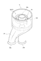
- FIG. 3A is a perspective view from above of the heat exchanger according to the embodiment
- FIG. 3B is a perspective view from below of the heat exchanger according to the embodiment.
- It is a perspective view of one cell part among a plurality of cell parts.
- It is a perspective view of a channel part.
- (A) is the perspective view of the adjustment mechanism of one Embodiment
- (b) is the top view which looked at (a) from upper direction.
- A) is the perspective view of the adjustment mechanism of one Embodiment
- (b) is the top view which looked at (a) from upper direction.
- FIG. 1 is a cross-sectional view schematically showing a plasma processing apparatus 50 which is an example of a substrate processing apparatus.
- the plasma processing apparatus 50 is a capacitively coupled parallel plate plasma etching apparatus, and includes a substantially cylindrical processing container 52.
- the processing container 52 is made of, for example, aluminum whose surface is anodized.
- the processing container 52 is grounded.
- a stage ST is disposed on the bottom of the processing container 52. As shown in FIG. 1, the stage ST includes a plate 2, a case 4, a heat exchanger 6, and a flow path portion 8. The stage ST will be described in detail with reference to FIG. FIG. 2 is an exploded perspective view of the stage ST.
- the stage ST shown in FIG. 2 is used as a mounting table for supporting the substrate in the processing container 52.
- the plate 2 has a disc shape and is made of a metal such as aluminum.
- the plate 2 has a front surface 2a and a back surface 2b.
- a substrate W can be placed on the surface 2 a of the plate 2.
- the case 4 is made of, for example, a metal such as stainless steel, and has a side wall 4a and a bottom wall 4b.
- the side wall 4a has a cylindrical shape and defines an accommodation space AS therein.
- the side wall 4a extends along the cylindrical axis direction and supports the plate 2 from below.
- the bottom wall 4b is connected to the lower end of the side wall 4a.
- An O-ring 10 that extends annularly along the upper end surface 4c may be provided on the upper end surface 4c of the side wall 4a.
- the plate 2 is airtightly fixed to the upper end surface 4c via an O-ring 10 by screwing, for example.
- the accommodation space AS is defined from above by the stage.
- a supply pipe 12 and a recovery pipe 14 are provided on the side wall 4a.
- the supply pipe 12 extends along the radial direction of the side wall 4 a and communicates with the accommodation space AS through the first opening 16.
- the collection pipe 14 extends along the radial direction of the side wall 4 a and communicates with the accommodation space AS through the second opening 18.
- FIG. 3A is a perspective view from above of the heat exchanger 6, and FIG. 3B is a perspective view from below.
- the heat exchanger 6 includes a partition wall 20, a plurality of first tubes 22, and a plurality of second tubes 24.
- the heat exchanger 6 is a plurality of regions on the back surface 2b of the plate 2, is two-dimensionally distributed, and individually supplies a heat exchange medium to the plurality of regions that are not included in each other. The medium is configured to be collected.
- the partition wall 20 has a substantially cylindrical shape as a whole, and has a plurality of substantially cylindrical columnar cell portions C. These cell parts C are coupled to each other.
- the plurality of cell portions C respectively define a plurality of spaces S having a circular cross-sectional shape. That is, the partition walls 20 are two-dimensionally distributed below the plate 2 and form a plurality of spaces S that are not included in each other.
- FIG. 4 is a perspective view of the cell portion C from above.
- Each of the plurality of first tubes 22 extends through a substantially central position of the corresponding space S in plan view.
- the plurality of first tubes 22 extend substantially parallel to each other toward the back surface 2b of the plate 2 (see FIG. 2).
- Each of the plurality of first tubes 22 is surrounded by a partition wall 20 that defines a surrounding space.
- Each of the plurality of first tubes 22 has a first opening end 22a and a second opening end 22b.
- the first opening end 22a is disposed so as to face the back surface 2b.
- the second opening end 22 b is located on the opposite side of the first opening end 22 a and is located below the space S.
- the plurality of first pipes 22 function as pipes that receive a heat exchange medium from a heat exchange medium supply device 42 described later and discharge the heat exchange medium from the first opening end 22a.
- the plurality of second tubes 24 are connected to the partition wall 20 so as to communicate with the plurality of spaces S, respectively.
- An opening 24 a is provided at the lower end of each of the plurality of second tubes 24.
- the plurality of second tubes 24 are discharged from the first open ends 22a of the plurality of first tubes 22, and the heat exchange medium collected in the space S surrounding the first tubes 22 is discharged to the outside. It functions as a tube.
- the space S surrounding the plurality of first tubes 22 has a plurality of flow paths FC for guiding the heat exchange medium discharged from the plurality of first opening ends 22a to the corresponding second tubes 24, respectively.
- the first pipe 22, the partition wall 20 that defines the space S surrounding the first pipe, and the second pipe 24 that communicates with the space S constitute a heat exchange unit. is doing. Therefore, the heat exchanger 6 has a plurality of heat exchange units arranged two-dimensionally so as not to be included in each other.
- Such a heat exchanger 6 can be configured with a resin as a main component.
- the heat exchanger 6 is formed using a 3D printer.
- a plurality of adjustment mechanisms 100 are provided in the plurality of spaces S, respectively. Each of these adjustment mechanisms 100 is deformed by the temperature of the heat exchange medium so that the conductance of the flow path FC becomes a conductance according to the temperature of the heat exchange medium flowing in the flow path FC. Details of the adjustment mechanism 100 will be described later.
- FIG. 5 is a perspective view of the flow path portion 8.
- the flow path portion 8 is disposed below the heat exchanger 6, and has a flow path for supplying a heat exchange medium to the heat exchanger 6 and a flow for recovering the heat exchange medium from the heat exchanger 6. Provide a road.
- the flow path portion 8 is a substantially cylindrical block body, and has an upper surface 8a and a side surface 8b. Further, the flow path portion 8 has a first aggregate portion 29 and a second aggregate portion 30 that protrude from the side surface 8b. A plurality of first flow paths 26 and a plurality of second flow paths 28 penetrating through the inside of the flow path portion 8 are formed. That is, the flow path portion 8 is formed with a plurality of small-diameter cavities that penetrate the interior of the flow path portion 8 from the upper surface 8a toward the first collective portion 29 or the second collective portion 30. These cavities constitute a plurality of first flow paths 26 and a plurality of second flow paths 28.
- the plurality of first flow paths 26 each have one end portion 26a and the other end portion 26b. These one end portions 26 a are formed at positions corresponding to the plurality of first tubes 22 of the heat exchanger 6 on the upper surface 8 a of the flow path portion 8, and the second openings of the plurality of first tubes 22. Each is connected to the end 22b. The other end portions 26 b of the plurality of first flow paths 26 are collected locally in the first collecting portion 29.
- the first collecting portion 29 is formed at a position corresponding to the first opening 16 of the case 4 and faces the first opening 16 in a state of being accommodated in the case 4.
- the plurality of second flow paths 28 each have one end 28a and the other end 28b.
- One end portions 28a of the plurality of second flow paths 28 are formed at positions corresponding to the openings 24a of the plurality of second tubes 24 of the heat exchanger 6 on the upper surface 8a of the flow path section 8, respectively.
- the second pipe 24 is connected to the opening 24a.
- the other end portions 28 b of the plurality of second flow paths 28 are collected locally in the second collecting portion 30.
- the second collecting portion 30 is formed at a position corresponding to the second opening 18 of the case 4, and faces the second opening 18 in a state of being accommodated in the case 4.
- the flow path portion 8 can be configured with resin as a main component.
- An electrostatic chuck 54 is provided on the surface 2a of the plate 2 of the stage ST.
- the electrostatic chuck 54 has a structure in which an electrode 56 that is a conductive film is disposed between a pair of insulating layers or insulating sheets.
- a DC power source 58 is electrically connected to the electrode 56.
- the electrostatic chuck 54 can electrostatically hold the substrate W by an electrostatic force such as a Coulomb force generated by a DC voltage from a DC power source 58.
- the supply pipe 12 and the recovery pipe 14 of the case 4 are connected to one end of a first pipe 40a and a second pipe 40b, respectively (see FIG. 2).
- the other ends of the first pipe 40a and the second pipe 40b are connected to a supply port and a recovery port of a heat exchange medium supply device 42 provided outside the processing container 52, respectively.
- the heat exchange medium supply device 42 adjusts the temperature of the heat exchange medium recovered from the second pipe 40b through the recovery port to the target temperature of the stage ST, and supplies the heat exchange medium adjusted to the target temperature of the stage ST. It supplies to the 1st piping 40a through a mouth. For example, when the target temperature of the stage ST is 50 ° C., the heat exchange medium adjusted to 50 ° C.
- the heat exchange medium is a fluid that circulates in the stage ST for the purpose of exchanging heat with the plate 2 and includes a refrigerant that absorbs heat from the plate 2 and a heat medium that gives heat to the plate 2. It is.
- the heat exchange medium for example, water, a fluorinated liquid, or the like is used.
- the heat exchange medium supplied from the heat exchange medium supply device 42 passes through the first pipe 40 a, the supply pipe 12, the plurality of first flow paths 26, and the first opening ends 22 a of the plurality of first pipes 22. It is discharged toward the back surface 2b of the plate 2. Then, the heat exchange medium recovered in the plurality of second tubes 24 is returned to the heat exchange medium supply device 42 via the plurality of second flow paths 28, the recovery tubes 14, and the second piping 40b. As described above, the heat exchange medium circulates between the heat exchange medium supply device 42 and the stage ST, so that the temperature of the substrate W placed on the electrostatic chuck 54 is controlled to be the target temperature.
- the temperature of the heat exchange medium supplied from the heat exchange medium supply device 42 can be controlled by a control unit Cnt described later.
- an upper electrode 60 is provided in the processing container 52.
- the upper electrode 60 is disposed opposite to the plate 2 above the plate 2 functioning as a lower electrode, and the plate 2 and the upper electrode 60 are provided substantially parallel to each other.
- the upper electrode 60 functions as a means for generating plasma together with the lower electrode.
- a processing space PS for performing plasma etching on the substrate W is defined between the upper electrode 60 and the plate 2, for example.
- the upper electrode 60 is supported on the upper portion of the processing container 52 through an insulating shielding member 62.
- the upper electrode 60 can include an electrode plate 64 and an electrode support 66.
- the electrode plate 64 faces the processing space PS and defines a plurality of gas discharge holes 64a.
- the electrode plate 64 can be made of a low resistance conductor or semiconductor with little Joule heat.
- the electrode plate 64 is grounded.
- the electrode support 66 supports the electrode plate 64 in a detachable manner, and may be made of a conductive material such as aluminum.
- the electrode support 66 may have a water cooling structure.
- a gas diffusion chamber 66a is provided inside the electrode support 66.
- a plurality of gas flow holes 66b communicating with the gas discharge holes 64a extend downward from the gas diffusion chamber 66a.
- the electrode support 66 is formed with a gas introduction port 66c for introducing a processing gas into the gas diffusion chamber 66a, and a gas supply pipe 68 is connected to the gas introduction port 66c.
- a gas source 70 is connected to the gas supply pipe 68 via a valve 72 and a mass flow controller (MFC) 74.
- An FCS may be provided instead of the MFC.
- the gas source 70 is a processing gas source.
- the processing gas from the gas source 70 reaches the gas diffusion chamber 66a from the gas supply pipe 68, and is discharged into the processing space PS through the gas flow hole 66b and the gas discharge hole 64a.
- the gas supply pipe 68 and the gas source 70 function as a means for supplying gas.
- the plasma processing apparatus 50 may further include a ground conductor 52a.
- the ground conductor 52 a is a substantially cylindrical ground conductor, and is provided so as to extend above the height position of the upper electrode 60 from the side wall of the processing container 52.
- a deposition shield 76 is detachably provided along the inner wall of the processing container 52.
- the deposition shield 76 is also provided on the outer periphery of the stage ST.
- the deposition shield 76 prevents the etching by-product (depot) from adhering to the processing container 52, and may be configured by coating an aluminum material with ceramics such as Y 2 O 3 .
- an exhaust plate 78 is provided between the stage ST and the inner wall of the processing container 52.
- the exhaust plate 78 can be configured by, for example, coating an aluminum material with ceramics such as Y 2 O 3 .
- an exhaust port 52 e is provided in the processing container 52.
- An exhaust device 80 is connected to the exhaust port 52e via an exhaust pipe 53.
- the exhaust device 80 includes a vacuum pump such as a turbo molecular pump, and can reduce the pressure in the processing container 52 to a desired degree of vacuum.
- a loading / unloading port 52 g for the substrate W is provided on the side wall of the processing container 52, and the loading / unloading port 52 g can be opened and closed by a gate valve 81.
- the plasma processing apparatus 50 further includes a high frequency power supply HFG, a high frequency power supply LFG, a matching unit MU1, and a matching unit MU2.
- the high frequency power supply HFG generates high frequency power for plasma generation, and supplies high frequency power of 27 MHz or higher, for example, 40 MHz, to the plate 2 via the matching unit MU1.
- the matching unit MU1 has a circuit that matches the internal (or output) impedance of the high-frequency power supply HFG to the load impedance.
- the high frequency power supply LFG generates a high frequency bias power for ion attraction, and supplies a high frequency bias power of 13.56 MHz or less, for example, 3 MHz to the plate 2 via the matching unit MU2.
- the matching unit MU2 includes a circuit that matches the internal (or output) impedance of the high-frequency power supply LFG to the load impedance.
- the lower electrode may be provided separately from the plate 2.
- the plasma processing apparatus 50 may further include a control unit Cnt.
- the control unit Cnt is a computer including a processor, a storage unit, an input device, a display device, and the like, and controls each unit of the plasma processing apparatus 50, such as a power supply system, a gas supply system, and a drive system.
- an operator can perform command input operations and the like to manage the plasma processing apparatus 50 using the input device, and the operating status of the plasma processing apparatus 50 is visualized by the display device. Can be displayed.
- the storage unit of the control unit Cnt causes the respective components of the plasma processing apparatus 50 to execute processes according to a control program for controlling various processes executed by the plasma processing apparatus 50 by the processor and processing conditions.
- a program for processing, that is, a processing recipe is stored.
- FIG. 6A is a perspective view of the adjustment mechanism 100 according to an embodiment.
- FIG. 6A a part of the partition wall 20 of the heat exchanger 6 is cut away.
- FIG. 6B is a plan view of FIG. 6A viewed from above.
- the adjusting mechanism 100 is disposed in a flow path FC formed between the partition wall 20 and the first tube 22 as shown in FIG.
- the adjustment mechanism 100 adjusts the conductance of the flow path FC to the conductance according to the temperature of the heat exchange medium by deforming according to the temperature of the heat exchange medium flowing in the flow path FC. More specifically, the adjustment mechanism 100 operates in either the steady mode or the first correction mode in which the conductance of the flow channel FC is different depending on the temperature of the heat exchange medium flowing in the flow channel FC. .
- the adjustment mechanism 100 includes a first annular plate 102, a second annular plate 104, and a deformation portion 106.
- the first annular plate 102 and the second annular plate 104 are annular plate members in which a center hole is formed, and the first tube 22 and the partition wall 20 in a state where the first tube 22 is inserted into the center hole. Between.
- the first annular plate 102 and the second annular plate 104 can be made of any material such as resin or metal.
- the first annular plate 102 is disposed between the first tube 22 and the partition wall 20 so as to be rotatable about the central axis Z of the first tube 22.
- a first through hole 102a penetrating in the plate thickness direction is formed at a radial position that is separated from the central axis Z of the first annular plate 102 by a predetermined distance d.
- the first through hole 102a has a circular shape with a diameter D.
- a second annular plate 104 is provided below the first annular plate 102.
- the second annular plate 104 is an annular plate member having the same diameter as that of the first annular plate 102, and is fixedly disposed coaxially with the first annular plate 102.
- a second through-hole 104a penetrating in the plate thickness direction is formed at a radial position separated from the central axis Z of the second annular plate 104 by a predetermined distance d. That is, the second through-hole 104a is formed at a position through which the first through-hole 102a passes when viewed from the center axis Z direction when the first annular plate 102 rotates around the center axis Z. .
- the second through hole 104a has a circular shape with the same diameter as the first through hole 102a, that is, a diameter D.
- the first annular plate 102 and the second annular plate 104 face each other through a gap CL.
- the distance between the first annular plate 102 and the second annular plate 104, that is, the width w of the gap CL is smaller than the diameter D of the first through hole 102a and the second through hole 104a. .
- a deforming portion 106 is provided above the first annular plate 102.
- the deforming portion 106 is deformed by the temperature, and the first annular plate is changed such that the relative distance between the first through hole 102a and the second through hole 104a in the circumferential direction changes with respect to the central axis Z. It has a function of rotating 102 around the central axis Z.
- the deformable portion 106 is a belt-like body formed by bonding a curved plate material having a relatively high thermal expansion coefficient and a curved plate material having a relatively low thermal expansion coefficient. It is spirally wound around the first tube 22 so as to face the outside. That is, the deformable portion 106 is composed of a bimetallic structure in which two plate materials having different thermal expansion coefficients are bonded together.
- the deformation part 106 has one end and the other end. One end of the deformable portion 106 is fixed to the outer surface of the first tube 22. The other end of the deforming portion 106 is connected to the first annular plate 102 via a connecting portion 106C.
- the deformed portion 106 is deformed such that when the temperature increases, the outer curved plate material of the deformable portion 106 expands as compared with the inner curved plate material, and the curvature increases. That is, when the temperature of the deforming portion 106 increases, the deforming portion 106 deforms so as to shrink inward when viewed from the central axis Z direction. On the other hand, when the temperature is lowered, the deforming portion 106 is deformed so that the curved plate material on the outer side of the deformable portion 106 contracts as compared with the curved plate material on the inner side and the curvature becomes smaller. That is, when the temperature of the deforming portion 106 decreases, the deforming portion 106 deforms so as to spread outward as viewed from the central axis Z.
- the steady mode is an operation mode for maintaining the temperature of the stage ST.
- the adjustment mechanism 100 operates as a steady mode when the deforming unit 106 is in a steady state.
- the deforming unit 106 enters a steady state when the temperature of the deforming unit 106 matches the target temperature (reference temperature) of the stage ST.
- the first through hole 102a is arranged at a position that does not overlap the second through hole 104a when viewed from the central axis Z direction.
- the heat exchange medium that is discharged from the first open end 22a of the first pipe 22 and flows through the flow path FC flows through the first through hole 102a, the gap CL, The second pipe 24 is recovered through the two through holes 104a. Since the width w of the gap CL between the first annular plate 102 and the second annular plate 104 is smaller than the diameter D of the first through hole 102a and the second through hole 104a, the first through hole 102a When arranged in a position that does not overlap with the second through-hole 104a when viewed from the central axis Z direction, the cross-sectional area of the flow path of the heat exchange medium is small. Therefore, when the adjustment mechanism 100 is operating in the steady mode, the conductance of the heat exchange medium flow path FC becomes smaller than when the adjustment mechanism 100 is set to a first correction mode described later.
- FIG. 7A is a perspective view of the adjustment mechanism 100 operating in the first correction mode
- FIG. 7B is a plan view of FIG. 7A viewed from above.
- the first correction mode is an operation mode for returning the temperature of the stage ST from the first temperature lower than the target temperature of the stage ST to the target temperature.
- the adjustment mechanism 100 operates in the first operation mode when the temperature of the deforming portion 106 reaches a first temperature lower than the target temperature of the stage ST.
- the first through hole 102a is arranged at a position overlapping the second through hole 104a when viewed from the central axis Z direction.
- the deforming portion 106 deforms so as to spread outward around the central axis Z. Due to such deformation, the position of the connecting portion 106C connected to the end of the deformable portion 106 is opposite to the winding direction of the deformable portion 106 in the circumferential direction of the first annular plate 102 (that is, FIG. 7B). (Clockwise direction). Along with this, the first annular plate 102 rotates in the direction opposite to the winding direction of the deformable portion 106, and the first through hole 102a moves in a direction approaching the second through hole 104a. As a result, the first through hole 102a is arranged at a position overlapping the second through hole 104a when viewed from the central axis Z direction.
- the heat exchange medium discharged from the first opening end 22a of the first tube 22 and flowing through the flow path FC is in contact with the first annular plate 102 and the first annular plate 102. Without passing through the clearance CL between the two annular plates 104, the second pipe 24 is recovered through the first through hole 102a and the second through hole 104a. Therefore, when the first through hole 102a is disposed on the second through hole 104a, the cross-sectional area of the flow path of the heat exchange medium is increased. Therefore, when the adjustment mechanism 100 is operating in the first correction mode, the conductance of the flow path FC of the heat exchange medium is greater than when the adjustment mechanism 100 is operating in the steady mode.
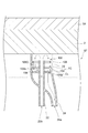
- FIG. 8 is a cross-sectional view schematically showing the flow of the heat exchange medium in the heat exchanger 6 when the adjustment mechanism 100 is operating in the steady mode.
- the heat exchange medium supplied into the stage ST from the first opening 16 by the heat exchange medium supply device 42 passes through the plurality of first flow paths 26 of the flow path section 8 and passes through the second opening end 22b. Respectively flow into the plurality of first tubes 22.
- the heat exchange medium flowing in from the second opening end 22b moves upward along the plurality of first tubes 22, and is discharged from the first opening end 22a toward the back surface 2b of the plate 2.
- the heat exchange medium released from the first opening end 22a exchanges heat with the plate 2 by contacting the back surface 2b of the plate 2 facing the first opening end 22a.
- the heat exchange medium that has exchanged heat with the plate 2 moves downward through the flow path FC.
- the heat exchange medium flowing through the flow path FC passes through the first through hole 102a, the gap CL between the first annular plate 102 and the second annular plate 104, and the second through hole 104a.
- the heat exchange medium that has flowed into the second pipe 24 is discharged to the outside of the space S from the opening 24 a of the second pipe 24.
- the heat exchange medium discharged from the space S is returned to the heat exchange medium supply device 42 via the plurality of second flow paths 28 and the second openings 18 connected to the openings 24a.
- FIG. 9 is a cross-sectional view schematically showing the flow of the heat exchange medium in the heat exchanger 6 when the adjustment mechanism 100 is operating in the first correction mode.
- the first through hole 102a is arranged at a position overlapping the second through hole 104a when viewed from the central axis Z direction. That is, the adjustment mechanism 100 is set to the first correction mode.
- the heat exchange medium flowing through the flow path FC is between the first annular plate 102 and the second annular plate 104. It will flow to the 2nd pipe
- the heat exchange medium The amount of heat given to the stage ST will increase. That is, when the adjustment mechanism 100 operates in the first correction mode, heating is performed so as to return the temperature of the stage ST to the target temperature. When the temperature of the stage ST is returned to the target temperature by this heating, the deforming portion 106 returns to the steady state, and the adjustment mechanism 100 operates again in the steady mode.
- the adjustment mechanism 100 adjusts the flow rate of the heat exchange medium so that the temperature of the stage ST is returned to the target temperature. Since this adjustment is performed inside the flow path FC of the heat exchanger 6, even if the temperature of the stage ST is lowered due to a disturbance, the temperature of the stage ST is corrected to the target temperature in a short time. It becomes possible. Furthermore, in the above-described stage ST, the conductance of the flow path FC is adjusted by the adjustment mechanism 100 being deformed according to the temperature of the heat exchange medium flowing inside the flow path FC, so that the control is not performed from the outside. It becomes possible to autonomously control the temperature of the stage ST.
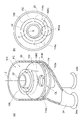
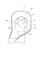
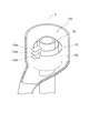
- FIG. 10A is a perspective view showing an adjustment mechanism 110 according to another embodiment.
- FIG. 10B is a plan view from above of FIG.
- the description same as the above-mentioned adjustment mechanism 100 is abbreviate
- the adjustment mechanism 110 includes a second annular plate 114 instead of the second annular plate 104.
- a second through hole 114a and a third through hole 114b are formed at a radial position spaced from the central axis Z of the second annular plate 114 by a predetermined distance d. That is, the second through hole 114a and the third through hole 114b pass through the first through hole 102a when viewed from the central axis Z when the first annular plate 102 rotates around the central axis Z. Formed in position.
- the 2nd through-hole 114a and the 3rd through-hole 114b are exhibiting the same diameter as the 1st through-hole 102a, ie, the circle of diameter D.
- the adjustment mechanism 110 is one of a steady mode, a first correction mode, and a second correction mode in which the conductance of the flow channel FC differs according to the temperature of the heat exchange medium flowing in the flow channel FC. Operates in operation mode.
- the adjustment mechanism 110 operates as a steady mode when the deformation unit 106 is in a steady state.
- the adjustment mechanism 110 operates in the first correction mode when the deforming unit 106 reaches a first temperature lower than the target temperature of the stage ST, and the adjusting unit 110 has a first temperature higher than the target temperature of the stage ST. When the temperature reaches 2, the operation is performed in the second correction mode.
- the steady mode is an operation mode for maintaining the temperature of the stage ST.
- the first through hole 102a is formed with the second through hole 114a and the second through hole as viewed from the central axis Z direction. 3 between the through holes 114b.
- the second through hole 114a is disposed at one position in the circumferential direction with respect to the circumferential position where the first through hole 102a is disposed at the target temperature (reference temperature).
- the three through holes 114b are arranged at the other side position in the circumferential direction with respect to the circumferential position where the first through hole 102a is arranged at the target temperature.
- the first through hole 102a When the first through hole 102a is disposed at a position that does not overlap the second through hole 104a when viewed from the central axis Z direction, the first through hole 102a is discharged from the first opening end 22a of the first tube 22 and is flowed.
- the heat exchange medium flowing through the FC passes through the first through hole 102a and the gap CL, and is collected in the second tube 24 through the second through hole 114a or the third through hole 114b.
- the width w of the gap CL between the first annular plate 102 and the second annular plate 104 is smaller than the diameter D of the first through hole 102a and the second through hole 104a.
- the cross-sectional area of the flow path of the heat exchange medium is small. Therefore, when the adjustment mechanism 110 is operating in the steady mode, the conductance of the flow path FC of the heat exchange medium is smaller than when the adjustment mechanism 110 is set to the first or second correction mode described later.
- FIG. 11A is a perspective view of the adjustment mechanism 100 operating in the first correction mode
- FIG. 11B is a plan view of FIG. 11A viewed from above.
- the first correction mode is an operation mode for returning the temperature of the stage ST from the first temperature lower than the target temperature of the stage ST to the target temperature.
- the first through hole 102a is disposed at a position overlapping the second through hole 114a when viewed from the central axis Z direction.
- the deforming portion 106 moves outward as viewed from the central axis Z. Deforms to spread. Due to such deformation, the position of the connecting portion 106C connected to the end of the deformable portion 106 is opposite to the winding direction of the deformable portion 106 in the circumferential direction of the first annular plate 102 (that is, FIG. 11B). (Clockwise direction). Along with this, the first annular plate 102 rotates in the direction opposite to the winding direction of the deformable portion 106, and the first through hole 102a moves in a direction approaching the second through hole 104a. As a result, the first through hole 102a is disposed at a position overlapping the second through hole 114a when viewed from the central axis Z direction.
- the adjustment mechanism 110 When the adjustment mechanism 110 is operating in the first correction mode, the heat exchange medium discharged from the first opening end 22a of the first pipe 22 and flowing through the flow path FC is in contact with the first annular plate 102 and the first annular plate 102. Without passing through the gap CL between the second annular plate 104, the second pipe 24 is recovered through the first through hole 102a and the second through hole 114a. Therefore, when the first through hole 102a is disposed on the second through hole 114a, the cross-sectional area of the flow path of the heat exchange medium is increased. Therefore, when the adjustment mechanism 110 is operating in the first correction mode, the conductance of the flow path FC of the heat exchange medium is greater than when the adjustment mechanism 110 is operating in the steady mode.
- the flow rate of the heat exchange medium flowing through the flow path FC increases.
- the amount of heat exchange between the heat exchange medium and the stage ST increases.
- the heat exchange medium set to the target temperature of the stage ST gives heat to the stage ST that is the first temperature.
- the heat exchange medium The amount of heat given to the stage ST will increase. That is, when the adjustment mechanism 110 operates in the first correction mode, the stage ST is heated so that the temperature of the stage ST returns to the target temperature. By this heating, the temperature of the stage ST is corrected so as to approach the target temperature.
- the deforming unit 106 returns to the steady state, and the adjustment mechanism 110 again operates in the steady mode.
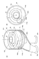
- FIG. 12A is a perspective view of the adjustment mechanism 110 operating in the second correction mode
- FIG. 12B is a plan view of FIG. 12A viewed from above.
- the second correction mode is an operation mode for returning the temperature of the stage ST from the second temperature higher than the target temperature of the stage ST to the target temperature.
- the first through hole 102a is arranged at a position overlapping the third through hole 114b when viewed from the central axis Z direction.
- the deforming portion 106 is deformed so as to be contracted inward as viewed from the central axis Z. Due to such deformation, the position of the connecting portion 106C connected to the end of the deformable portion 106 is set in the winding direction of the deformable portion 106 in the circumferential direction of the first annular plate 102 (ie, the counterclockwise of FIG. 12B). Move around).
- the first annular plate 102 rotates in the same direction as the winding direction of the deformable portion 106, and the first through hole 102 a is in the circumferential direction around the central axis Z with respect to the third through hole 114 b. Move in the direction of approach. As a result, the first through hole 102a is disposed on the third through hole 114b.
- the adjustment mechanism 110 When the adjustment mechanism 110 is operating in the second correction mode, the heat exchange medium discharged from the first opening end 22a of the first pipe 22 and flowing through the flow path FC is in contact with the first annular plate 102 and the first annular plate 102. Without passing through the gap CL between the two annular plates 104, the second pipe 24 is recovered through the first through hole 102a and the third through hole 114b. Therefore, when the first through hole 102a is disposed on the third through hole 114b, the cross-sectional area of the flow path of the heat exchange medium is increased. Therefore, when the adjustment mechanism 110 is operating in the second correction mode, the conductance of the heat exchange medium flow path FC is greater than when the adjustment mechanism 110 is operating in the steady mode.
- the flow rate of the heat exchange medium flowing through the flow path FC increases.
- the amount of heat exchange between the heat exchange medium and the stage ST increases.
- the heat exchange medium set at the target temperature of the stage ST takes heat away from the stage ST that is the second temperature.
- the heat exchange medium is removed.
- the amount of heat taken away from the stage ST will increase. That is, when the adjustment mechanism 110 operates in the second correction mode, the stage ST is cooled so that the temperature of the stage ST is returned to the target temperature. By this cooling, the temperature of the stage ST is corrected so as to approach the target temperature.
- the deforming unit 106 returns to the steady state, and the adjustment mechanism 110 operates again in the steady mode.
- the temperature of the stage ST can be set to the target temperature in a short time by increasing the flow rate of the heat exchange medium. It becomes possible to correct. Further, according to the adjustment mechanism 110, both when the temperature of the stage ST becomes a first temperature lower than the target temperature and when the temperature of the stage ST becomes a second temperature higher than the target temperature. Thus, the temperature of the stage ST can be corrected to the target temperature.
- FIG. 13 is a perspective view showing an adjustment mechanism 120 according to still another embodiment.
- the outer edge of the first tube 22 may have a rectangular cross-sectional shape.
- the partition wall 20 can define a space having a rectangular cross-sectional shape between the partition wall 20 and the first tube 22.
- the adjustment mechanism 120 is composed of a plurality of plate-like bodies 124.
- the plate-like bodies 124 are provided along the four outer surfaces of the first tube 22.
- the plate-like body 124 is configured such that the distance between the other end 124b described later and the first tube 22 changes according to the temperature of the heat exchange medium.
- These plate-like bodies 124 are plate-like members obtained by laminating a plate material having a relatively high thermal expansion coefficient and a plate material having a relatively low thermal expansion coefficient. It arrange
- Each of the plurality of plate-like bodies 124 has one end portion 124a and the other end portion 124b.
- One end portion 124 a of the plate-like body 124 is fixed to the upper portion of the outer surface of the first tube 22.
- the other end 124b of the plate-like body 124 is located below the one end 124a.
- the other end 124b is free without being fixed to the outer surface of the first tube 22.
- These plate-like bodies 124 are in a steady state when the temperature thereof matches the target temperature of the stage ST. In this steady state, as shown in FIG. 13, each of the plurality of plate-like bodies 124 is curved so as to gradually approach the partition wall 20 as it approaches the other end 124b from the one end 124a.
- the plate material provided on the first tube 22 side of the plate-like body 124 expands as compared with the plate material provided on the partition wall 20 side so that the curvature increases.
- the plate material provided on the first tube 22 side of the plate-like body 124 contracts as compared with the plate material provided on the partition wall 20 side, thereby reducing the curvature. It deforms as follows.
- the flow of the heat exchange medium inside the stage ST when the temperature of the stage ST is lowered due to a disturbance will be described with reference to FIG.
- FIG. 14B when the substrate W having a temperature lower than the target temperature of the stage ST is placed on the stage ST, the temperature of the plate 2 decreases. Along with this, the heat of the heat exchange medium discharged toward the plate 2 is taken away by the plate 2, and the temperature of the heat exchange medium flowing through the flow path FC becomes lower than the target temperature of the stage ST. Thereby, the plate-like body 124 arranged in the flow path FC is cooled by the heat exchange medium. When the plate-like body 124 is cooled, the plate-like body 124 is deformed so that the curvature toward the partition wall 20 is reduced.
- the flow rate of the heat exchange medium flowing through the flow path FC increases.
- the amount of heat given from the heat exchange medium to the stage ST increases. Therefore, when the temperature of the stage ST becomes lower than the target temperature, the temperature of the stage ST is corrected so as to approach the target temperature.
- the plate-like body 124 returns to the steady state, and the flow rate of the heat exchange medium is reduced again.
- the temperature of the stage ST can be set to the target temperature in a short time by increasing the flow rate of the heat exchange medium. It becomes possible to correct.
- FIG. 15 is a perspective view showing an adjusting mechanism 130 according to still another embodiment.
- the description same as the above-mentioned adjustment mechanism 100 is abbreviate
- the adjusting mechanism 130 includes a deforming portion 132 instead of the first annular plate 102, the second annular plate 104, and the deforming portion 106.
- the deformable portion 132 is a strip-shaped plate material in which a curved plate material having a relatively high thermal expansion coefficient and a curved plate material having a relatively low thermal expansion coefficient are bonded to each other, and the curved plate material having a relatively high thermal expansion coefficient is disposed inside. It is wound spirally around the first tube 22 so as to face. That is, the deformable portion 132 has a bimetallic structure in which two plate materials having different thermal expansion coefficients are bonded together.
- the deformation part 132 has one end and the other end. One end of the deformable portion 132 is fixed to the outer surface of the first tube 22. Further, the deformable portion 132 is provided with a first projecting plate portion 132 a, a second projecting plate portion 132 b, and a third projecting plate portion 132 c provided so as to project toward the partition wall 20. The first projecting plate portion 132 a is provided near one end of the deformable portion 132, and the third projecting plate portion 132 c is provided at the other end of the deformable portion 132.
- the second protruding plate portion 132 b is provided between the first protruding plate portion 132 a and the third protruding plate portion 132 c in the length direction of the deformable portion 132. Further, the first protruding plate portion 132a, the second protruding plate portion 132b, and the third protruding plate portion 132c are provided at different positions in the height direction.
- the adjustment mechanism 130 operates in one of the steady mode and the first correction mode according to the temperature of the heat exchange medium flowing in the flow path FC.
- the adjustment mechanism 130 operates as a steady mode when the deforming portion 132 is in a steady state.
- the adjustment mechanism 130 operates in the first correction mode when the deforming unit 132 reaches a first temperature lower than the target temperature of the stage ST.
- the steady mode is an operation mode for maintaining the temperature of the stage ST.
- the first projecting plate portion 132a, the second projecting plate portion 132b, and the third projecting plate portion 132c are arranged at positions that do not overlap each other when viewed from the direction of the central axis Z. Is done.
- the flow of the heat exchange medium in the flow path FC is hindered by each of the first protruding plate portion 132a, the second protruding plate portion 132b, and the third protruding plate portion 132c.
- the conductance of the flow path FC becomes smaller than the first correction mode described later.
- FIG. 16 is a perspective view of the adjustment mechanism 100 operating in the first correction mode.
- the first correction mode is an operation mode for returning the temperature of the stage ST from the first temperature lower than the target temperature of the stage ST to the target temperature.
- the first projecting plate portion 132a, the second projecting plate portion 132b, and the third projecting plate portion 132c are disposed so as to overlap each other when viewed from the central axis Z direction.
- the deformable portion 132 is seen from the center axis Z direction. Deforms to shrink. As a result of such deformation, as shown in FIG. 16, the first projecting plate portion 132a, the second projecting plate portion 132b, and the third projecting plate portion 132c overlap each other when viewed from the central axis Z direction. Be placed.
- the flow of the heat exchange medium in the flow path FC is hindered only by the first projecting plate portion 132a, so that the conductance of the flow path FC of the heat exchange medium compared to the steady mode. Becomes larger.
- the conductance of the heat exchange medium increases, the flow rate of the heat exchange medium flowing through the flow path FC increases.
- the amount of heat exchange between the heat exchange medium and the stage ST increases. Therefore, when the adjustment mechanism 110 operates in the first correction mode, the stage ST is heated so that the temperature of the stage ST returns to the target temperature. By this heating, the temperature of the stage ST is corrected so as to approach the target temperature.
- the deforming unit 132 returns to the steady state, and the adjustment mechanism 130 operates again in the steady mode.
- the temperature of the stage ST can be set to the target temperature in a short time by increasing the flow rate of the heat exchange medium. It becomes possible to correct.
- the stage of various embodiments is applied to the plasma processing apparatus, but the target to which the stage is applied is not limited to the plasma processing apparatus, and can be applied to any substrate processing apparatus. .
- the adjusting mechanisms 100, 120, and 130 described above are configured to increase the conductance of the flow path FC when the temperature of the heat exchange medium is lower than the temperature of the stage ST.
- the conductance of the flow path FC may be increased when the temperature is higher than the temperature of the stage ST.
- Such a configuration can be realized, for example, by designing the bimetal structure so that the deformation direction corresponding to the temperature change is opposite to that in the above-described embodiment.
Landscapes
- Physics & Mathematics (AREA)
- Engineering & Computer Science (AREA)
- Plasma & Fusion (AREA)
- Chemical & Material Sciences (AREA)
- Analytical Chemistry (AREA)
- Drying Of Semiconductors (AREA)
- Container, Conveyance, Adherence, Positioning, Of Wafer (AREA)
Abstract
Description
Claims (6)
- 基板が載置される表面と裏面とを有するプレートと、
各々が前記裏面の異なる領域に向けて延びて、前記裏面に対面する開口端を提供する複数の第1の管と、
前記複数の第1の管をそれぞれ囲む複数の空間を画成する隔壁であり、該複数の空間がそれぞれ前記複数の第1の管から吐出される熱交換媒体が流れる複数の流路を構成する、該隔壁と、
前記複数の流路にそれぞれ連通するよう前記隔壁に接続された複数の第2の管と、
前記複数の流路内にそれぞれ設けられた複数の調整機構であり、各々が対応の流路の熱交換媒体の温度に応じて変形して該流路のコンダクタンスを該温度に応じて調整するように構成された該複数の調整機構と、
を備えるステージ。 - 前記複数の調整機構の各々は、少なくともその一部が熱膨張率の異なる2枚の板材を貼り合わせたバイメタル構造体から構成されている、
請求項1に記載のステージ。 - 前記複数の調整機構の各々は、
前記第1の管の中心軸線を中心に回転可能なように、前記第1の管と前記隔壁との間に設けられた第1の環状板であり、前記中心軸線から所定の距離だけ離間した径方向の位置に板厚方向に貫通する第1の貫通孔が形成された該第1の環状板と、
前記第1の環状板に対面するように固定配置された第2の環状板であり、前記中心軸線から前記所定の距離だけ離間した径方向の位置に板厚方向に貫通する第2の貫通孔が形成された該第2の環状板と、
前記熱交換媒体の温度に応じて変形して、前記中心軸線に対して周方向における前記第1の貫通孔と前記第2の貫通孔との相対的距離が変化するように、前記第1の環状板を前記中心軸線を中心に回転させる変形部と、
を含む、請求項1又は2に記載のステージ。 - 前記第2の環状板には、前記中心軸線から前記所定の距離だけ離間した径方向の位置に板厚方向に貫通する第3の貫通孔が更に形成されており、
前記第2の貫通孔は、基準温度において前記第1の貫通孔が配置される前記周方向の位置に対して該周方向において一方側の位置に配置されており、
前記第3の貫通孔は、基準温度において前記第1の貫通孔が配置される前記周方向の位置に対して該周方向において他方側の位置に配置されている、
請求項3に記載のステージ。 - 前記調整機構の各々は、前記第1の管の外側面に沿って設けられた板状体であり、
前記板状体は、前記第1の管の外側面に固定された一端部と、前記第1の管の外側面に対して固定されていない他端部と、を有し、前記熱交換媒体の温度に応じて該他端部と前記第1の管との距離が変化するように構成されている、
請求項1又は2に記載のステージ。 - 処理容器と、
前記処理容器内に設けられた、請求項1~5の何れか一項に記載のステージと、
を備える基板処理装置。
Priority Applications (3)
| Application Number | Priority Date | Filing Date | Title |
|---|---|---|---|
| JP2016559009A JP6529512B2 (ja) | 2014-11-12 | 2015-11-05 | ステージ及び基板処理装置 |
| US15/526,723 US10658160B2 (en) | 2014-11-12 | 2015-11-05 | Stage and substrate processing apparatus |
| KR1020177012546A KR102000852B1 (ko) | 2014-11-12 | 2015-11-05 | 스테이지 및 기판 처리 장치 |
Applications Claiming Priority (2)
| Application Number | Priority Date | Filing Date | Title |
|---|---|---|---|
| JP2014-229995 | 2014-11-12 | ||
| JP2014229995 | 2014-11-12 |
Publications (1)
| Publication Number | Publication Date |
|---|---|
| WO2016076201A1 true WO2016076201A1 (ja) | 2016-05-19 |
Family
ID=55954290
Family Applications (1)
| Application Number | Title | Priority Date | Filing Date |
|---|---|---|---|
| PCT/JP2015/081187 Ceased WO2016076201A1 (ja) | 2014-11-12 | 2015-11-05 | ステージ及び基板処理装置 |
Country Status (4)
| Country | Link |
|---|---|
| US (1) | US10658160B2 (ja) |
| JP (1) | JP6529512B2 (ja) |
| KR (1) | KR102000852B1 (ja) |
| WO (1) | WO2016076201A1 (ja) |
Families Citing this family (2)
| Publication number | Priority date | Publication date | Assignee | Title |
|---|---|---|---|---|
| JP7306195B2 (ja) * | 2019-09-27 | 2023-07-11 | 東京エレクトロン株式会社 | 基板を処理する装置及びステージをクリーニングする方法 |
| US12474721B2 (en) | 2022-12-16 | 2025-11-18 | Hamilton Sundstrand Corporation | Controlling flow of a fluid using thermally deformable channel |
Citations (6)
| Publication number | Priority date | Publication date | Assignee | Title |
|---|---|---|---|---|
| JPH03212934A (ja) * | 1990-01-18 | 1991-09-18 | Tokyo Electron Sagami Ltd | 縦型熱処理装置 |
| JPH0513350A (ja) * | 1991-07-03 | 1993-01-22 | Tokyo Electron Yamanashi Kk | 基板処理装置 |
| JPH07224386A (ja) * | 1994-02-10 | 1995-08-22 | Anelva Corp | 基板保持機構 |
| JPH0845909A (ja) * | 1994-07-26 | 1996-02-16 | Sony Corp | 試料台 |
| JPH1154482A (ja) * | 1997-08-05 | 1999-02-26 | Hitachi Ltd | 半導体装置の製造方法および装置ならびにワークの処理方法 |
| JP2000182959A (ja) * | 1998-12-10 | 2000-06-30 | Canon Inc | 機能性部材の製造装置、機能性部材の製造方法及び機能性部材 |
Family Cites Families (9)
| Publication number | Priority date | Publication date | Assignee | Title |
|---|---|---|---|---|
| JPS60107116A (ja) * | 1983-11-16 | 1985-06-12 | Mitsubishi Electric Corp | 流量調整器 |
| US5591269A (en) * | 1993-06-24 | 1997-01-07 | Tokyo Electron Limited | Vacuum processing apparatus |
| JPH10284382A (ja) * | 1997-04-07 | 1998-10-23 | Komatsu Ltd | 温度制御装置 |
| CN1207939C (zh) * | 1999-09-29 | 2005-06-22 | 东京电子株式会社 | 多区电阻加热器 |
| JP2002025758A (ja) * | 2000-05-02 | 2002-01-25 | Ibiden Co Ltd | ホットプレートユニット |
| US7789962B2 (en) * | 2005-03-31 | 2010-09-07 | Tokyo Electron Limited | Device and method for controlling temperature of a mounting table, a program therefor, and a processing apparatus including same |
| JP4551256B2 (ja) | 2005-03-31 | 2010-09-22 | 東京エレクトロン株式会社 | 載置台の温度制御装置及び載置台の温度制御方法及び処理装置及び載置台温度制御プログラム |
| WO2009153735A1 (en) * | 2008-06-18 | 2009-12-23 | Brusa Elektronik Ag | Cooling system, in particular for electronic structural units |
| DE102011100706A1 (de) | 2011-05-06 | 2012-11-08 | GM Global Technology Operations LLC (n. d. Gesetzen des Staates Delaware) | Regelbarer Wärmetauscher für eine Kraftfahrzeug-Klimaanlage |
-
2015
- 2015-11-05 US US15/526,723 patent/US10658160B2/en active Active
- 2015-11-05 KR KR1020177012546A patent/KR102000852B1/ko active Active
- 2015-11-05 JP JP2016559009A patent/JP6529512B2/ja active Active
- 2015-11-05 WO PCT/JP2015/081187 patent/WO2016076201A1/ja not_active Ceased
Patent Citations (6)
| Publication number | Priority date | Publication date | Assignee | Title |
|---|---|---|---|---|
| JPH03212934A (ja) * | 1990-01-18 | 1991-09-18 | Tokyo Electron Sagami Ltd | 縦型熱処理装置 |
| JPH0513350A (ja) * | 1991-07-03 | 1993-01-22 | Tokyo Electron Yamanashi Kk | 基板処理装置 |
| JPH07224386A (ja) * | 1994-02-10 | 1995-08-22 | Anelva Corp | 基板保持機構 |
| JPH0845909A (ja) * | 1994-07-26 | 1996-02-16 | Sony Corp | 試料台 |
| JPH1154482A (ja) * | 1997-08-05 | 1999-02-26 | Hitachi Ltd | 半導体装置の製造方法および装置ならびにワークの処理方法 |
| JP2000182959A (ja) * | 1998-12-10 | 2000-06-30 | Canon Inc | 機能性部材の製造装置、機能性部材の製造方法及び機能性部材 |
Also Published As
| Publication number | Publication date |
|---|---|
| US20170316923A1 (en) | 2017-11-02 |
| JP6529512B2 (ja) | 2019-06-12 |
| JPWO2016076201A1 (ja) | 2017-08-17 |
| US10658160B2 (en) | 2020-05-19 |
| KR102000852B1 (ko) | 2019-07-16 |
| KR20170070115A (ko) | 2017-06-21 |
Similar Documents
| Publication | Publication Date | Title |
|---|---|---|
| JP6018606B2 (ja) | 温度制御可能なステージを含むシステム、半導体製造装置及びステージの温度制御方法 | |
| US10332772B2 (en) | Multi-zone heated ESC with independent edge zones | |
| US11978614B2 (en) | Substrate processing apparatus | |
| KR102311554B1 (ko) | 스테이지, 스테이지의 제조 방법, 열교환기 | |
| JP2018160462A (ja) | 温度制御機能を備えるマルチプレナムシャワーヘッド | |
| US12191122B2 (en) | Electrostatic chuck with spatially tunable RF coupling to a wafer | |
| TWI614590B (zh) | 流量調整裝置及處理裝置 | |
| KR102863314B1 (ko) | 기판 지지 어셈블리, 플라즈마 처리 장치, 및 플라즈마 처리 방법 | |
| CN103993293A (zh) | 带温度控制的多室喷头 | |
| US10763764B2 (en) | Stage and substrate processing apparatus | |
| CN105023823A (zh) | 等离子体生成单元以及包括其的基板处理装置 | |
| WO2016076201A1 (ja) | ステージ及び基板処理装置 | |
| US11804363B2 (en) | Chamber components for gas delivery modulation | |
| JP6545330B2 (ja) | ステージ、ステージの製造方法 | |
| KR20210018145A (ko) | 배치대 및 기판 처리 장치 | |
| KR20250078382A (ko) | 기판 처리 장치 | |
| KR20220134477A (ko) | 온도 제어 장치, 기판 처리 장치 및 압력 제어 방법 |
Legal Events
| Date | Code | Title | Description |
|---|---|---|---|
| 121 | Ep: the epo has been informed by wipo that ep was designated in this application |
Ref document number: 15859351 Country of ref document: EP Kind code of ref document: A1 |
|
| ENP | Entry into the national phase |
Ref document number: 2016559009 Country of ref document: JP Kind code of ref document: A |
|
| ENP | Entry into the national phase |
Ref document number: 20177012546 Country of ref document: KR Kind code of ref document: A |
|
| NENP | Non-entry into the national phase |
Ref country code: DE |
|
| WWE | Wipo information: entry into national phase |
Ref document number: 15526723 Country of ref document: US |
|
| 122 | Ep: pct application non-entry in european phase |
Ref document number: 15859351 Country of ref document: EP Kind code of ref document: A1 |