WO2016075744A1 - プロジェクタ及び映像表示方法 - Google Patents
プロジェクタ及び映像表示方法 Download PDFInfo
- Publication number
- WO2016075744A1 WO2016075744A1 PCT/JP2014/079758 JP2014079758W WO2016075744A1 WO 2016075744 A1 WO2016075744 A1 WO 2016075744A1 JP 2014079758 W JP2014079758 W JP 2014079758W WO 2016075744 A1 WO2016075744 A1 WO 2016075744A1
- Authority
- WO
- WIPO (PCT)
- Prior art keywords
- video
- image
- luminance level
- unit
- projector
- Prior art date
- Legal status (The legal status is an assumption and is not a legal conclusion. Google has not performed a legal analysis and makes no representation as to the accuracy of the status listed.)
- Ceased
Links
Images











Classifications
-
- H—ELECTRICITY
- H04—ELECTRIC COMMUNICATION TECHNIQUE
- H04N—PICTORIAL COMMUNICATION, e.g. TELEVISION
- H04N9/00—Details of colour television systems
- H04N9/12—Picture reproducers
- H04N9/31—Projection devices for colour picture display, e.g. using electronic spatial light modulators [ESLM]
- H04N9/3179—Video signal processing therefor
- H04N9/3185—Geometric adjustment, e.g. keystone or convergence
-
- H—ELECTRICITY
- H04—ELECTRIC COMMUNICATION TECHNIQUE
- H04N—PICTORIAL COMMUNICATION, e.g. TELEVISION
- H04N5/00—Details of television systems
- H04N5/74—Projection arrangements for image reproduction, e.g. using eidophor
-
- H—ELECTRICITY
- H04—ELECTRIC COMMUNICATION TECHNIQUE
- H04N—PICTORIAL COMMUNICATION, e.g. TELEVISION
- H04N9/00—Details of colour television systems
- H04N9/12—Picture reproducers
- H04N9/31—Projection devices for colour picture display, e.g. using electronic spatial light modulators [ESLM]
- H04N9/3179—Video signal processing therefor
- H04N9/3188—Scale or resolution adjustment
-
- H—ELECTRICITY
- H04—ELECTRIC COMMUNICATION TECHNIQUE
- H04N—PICTORIAL COMMUNICATION, e.g. TELEVISION
- H04N9/00—Details of colour television systems
- H04N9/77—Circuits for processing the brightness signal and the chrominance signal relative to each other, e.g. adjusting the phase of the brightness signal relative to the colour signal, correcting differential gain or differential phase
-
- G—PHYSICS
- G06—COMPUTING OR CALCULATING; COUNTING
- G06F—ELECTRIC DIGITAL DATA PROCESSING
- G06F3/00—Input arrangements for transferring data to be processed into a form capable of being handled by the computer; Output arrangements for transferring data from processing unit to output unit, e.g. interface arrangements
- G06F3/01—Input arrangements or combined input and output arrangements for interaction between user and computer
- G06F3/048—Interaction techniques based on graphical user interfaces [GUI]
- G06F3/0481—Interaction techniques based on graphical user interfaces [GUI] based on specific properties of the displayed interaction object or a metaphor-based environment, e.g. interaction with desktop elements like windows or icons, or assisted by a cursor's changing behaviour or appearance
- G06F3/0482—Interaction with lists of selectable items, e.g. menus
-
- G—PHYSICS
- G06—COMPUTING OR CALCULATING; COUNTING
- G06F—ELECTRIC DIGITAL DATA PROCESSING
- G06F3/00—Input arrangements for transferring data to be processed into a form capable of being handled by the computer; Output arrangements for transferring data from processing unit to output unit, e.g. interface arrangements
- G06F3/01—Input arrangements or combined input and output arrangements for interaction between user and computer
- G06F3/048—Interaction techniques based on graphical user interfaces [GUI]
- G06F3/0484—Interaction techniques based on graphical user interfaces [GUI] for the control of specific functions or operations, e.g. selecting or manipulating an object, an image or a displayed text element, setting a parameter value or selecting a range
- G06F3/04847—Interaction techniques to control parameter settings, e.g. interaction with sliders or dials
Definitions
- the present invention relates to a projector for projecting and displaying an image on a projection surface and an image display method, and more particularly to a technique for suitably reducing the blur of the projected image.
- a projector is installed on a horizontal surface such as a desk or a ceiling, and projects an image on a screen attached to a vertical surface such as a wall.
- the attitude of the projector is adjusted so that a clear image can be projected on the screen.
- not all projectors can be installed so that the installation surface and the screen surface are in a vertical relationship.
- the projector installed on the ceiling is projected onto the screen in front of the auditorium so that the image is distorted in a trapezoidal shape.
- portable projectors used in meeting rooms and the like often project from a desk, but they are not necessarily projected onto a vertical wall surface and are often displayed in a distorted manner as well.
- a technique for adjusting this so as to eliminate the distortion and form a rectangle is keystone correction (keystone correction).
- keystone correction keystone correction
- a trapezoidal image is converted into a rectangular shape by performing a geometric conversion operation such as reduction or enlargement on the projected video signal.
- Patent Document 1 discloses a technique for reducing the geometric blur of enlargement / reduction operation at the time of keystone correction by sharpness processing. Specifically, it is described that the screen is divided into a plurality of areas, and an adjustment value for sharpness adjustment is set for each divided area, and the sharpness adjustment of each area is performed based on the adjustment value.
- the projector lens is designed so that it is uniformly focused on the screen if the distance to the screen and the angle of projection are appropriate (hereinafter referred to as a reference setting).
- a reference setting the image of the portion exceeding the depth of field of the lens among the images in the rectangle is blurred due to the focus shift. That is, the range in which a suitable image can be obtained even when keystone correction is performed is extremely limited.
- the reference setting is used, if the lens design or accuracy is not appropriate, there is a problem that blur occurs at the edge of the screen due to a difference in projection distance from the center of the screen and aberration.
- the blur due to the difference in the projection distance when performing the keystone correction is particularly remarkable in the ultra-short projection projector and the wide-angle short projection projector in which the projection angle is steep at the screen edge of the projected image.
- projection mapping is often performed in the projection onto a three-dimensional object.
- a difference in focal length due to depth occurs, and thus there is a problem that blurring due to focus shift occurs when there is a distance difference greater than the depth of field.
- the present invention is to provide a projector and a video display method that suitably reduce video blur caused by the resolution of a projection optical system such as a focus shift of a lens.
- a video processing unit that performs video processing on the input video signal, and a video signal that has been video processed by the video processing unit are input to generate an optical image.
- the video correction unit changes the black luminance level of the video signal.
- an image display method for projecting and displaying an image on a projection surface, an image processing step for performing image processing on an input image signal, and an optical image by an image display element by inputting the image processing image signal.
- An optical image generation step for generating the image, and a projection step for projecting the generated optical image onto the projection surface by the projection optical system.
- the image processing step in order to reduce blur of the image projected by the projection optical system, It has a video correction function for changing the black luminance level of the video signal.
- the present invention it is possible to suitably reduce image blur caused by the resolution of the projection optical system such as a lens focus shift.
- FIG. 3 is a diagram illustrating a configuration of a projector according to the first embodiment.
- amendment part in FIG. The figure explaining the relationship between the focus by a convex lens, and a real image.
- FIG. 3 is a diagram for explaining a video signal correction method according to the first embodiment.
- FIG. 10 is a diagram illustrating a configuration of a video correction unit according to the second embodiment.
- FIG. 10 is a diagram illustrating a configuration of a video correction unit according to the third embodiment.
- FIG. 10 is a diagram illustrating a configuration of a video correction unit according to a fourth embodiment.
- FIG. 10 is a diagram illustrating a configuration of a video correction unit according to a fifth embodiment. The figure which shows the PSF data in a lens shift.
- FIG. 10 is a diagram illustrating a configuration of a video correction unit according to the second embodiment.
- FIG. 10 is a diagram illustrating a configuration of a video correction unit according to the third embodiment.
- FIG. 10 is a diagram illustrating a configuration of a video correction unit according to a fourth embodiment.
- FIG. 10 is a diagram illustrating a configuration of a video correction unit according to a fifth embodiment.
- FIG. 10 is a diagram illustrating a configuration of a video correction unit according to a sixth embodiment.
- Embodiment 1 describes a projector that performs resolution restoration processing by despreading process calculation.
- FIG. 1 is a diagram illustrating a configuration of a projector according to the first embodiment.
- the projector 1 receives a video input signal 100 output from a broadcast wave or a PC, inputs a display control signal 103 to a video processing unit 10 that processes the video signal, and a liquid crystal panel that is a video display element. It is comprised with the optical unit 20 which produces
- the video processing unit 10 receives the video input signal 100 and converts the internal video signal 101 into an internal video signal 101 by converting the internal video signal 101 by, for example, a decoder of compressed video signal, IP conversion, scaler, keystone correction, and the like.
- a video correction unit 12 that inputs and performs resolution restoration processing by a despreading process calculation described later and converts it into a corrected video signal 102, and the corrected video signal 102 are input.
- the timing control unit 13 for generating 103 is configured.
- the optical unit 20 receives the light source (lamp) 21 that generates the illumination light 201 and the display control signal 103 output from the video processing unit 10, adjusts the gradation of the illumination light 201 for each pixel, and the optical image 202.
- the projector 1 has a function of displaying a menu screen for a user to operate adjustment of brightness (brightness), contrast, hue, keystone, etc. of an image to be projected, input signal switching, and the like. Based on the above, the function of each unit is controlled by a control unit (not shown).
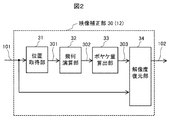
- FIG. 2 is a diagram showing the configuration of the video correction unit 12 in FIG.
- An image correction unit 30 (corresponding to reference numeral 12 in FIG. 1) includes a position acquisition unit 31 that acquires a pixel position 301 that matches the input signal in the projection optical system from the optical unit 20 to the screen 2, and each image signal in the image signal.
- a position acquisition unit 31 that acquires a pixel position 301 that matches the input signal in the projection optical system from the optical unit 20 to the screen 2, and each image signal in the image signal.
- a geometric calculation unit 32 that calculates a position 302 where the image light rays intersect on the lens
- a blur amount calculation unit 33 that calculates a blur amount 303 from the position 302 on the lens.
- a resolution restoration unit 34 that performs a despreading operation based on the internal video signal 101 and the blur amount 303.
- the geometric calculation unit 32 calculates the position 302 where the light rays intersect on the lens according to the Gaussian imaging formula from the pixel position 301 on the LCD 22 and the optical axis distance assumed from the set focus and zoom.
- the Gaussian imaging formula is expressed by Equation 1 where a is the distance from the object to the lens, b is the distance from the lens to the real image, and f is the focal point.
- FIG. 3 is a diagram for explaining the relationship between the focal point by the convex lens and the real image.
- the distance b to the real image 42 is determined by Equation 1.
- the object 41 is an image on the LCD 22, and the real image 42 is an image projected on the screen 2.
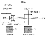
- FIG. 4A is a diagram showing the principle of the projected image in the projector.
- the image of the projector 1 is imaged by the illumination light generated from the lamp 21 through the LCD 22. This image is formed in accordance with the size and position of the screen 2 using the focus and zoom functions of the lens 23.
- the LCD image 51 in the figure is assumed to display a point P1 at the center of the screen.
- the point P1 is imaged on the screen 2 as a point P2 like the screen image 52. At that time, when the screen 2 is within the range of the depth of field D, the image blur is not felt.
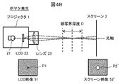
- FIG. 4B is a diagram illustrating the generation of a blurred image by the projector.
- the point P1 of the LCD image 51 is imaged as a point P2 'spread on the screen 2 like the screen image 52'. This causes image blur.
- the imaging blur in the camera will be described.
- a focus shift occurs with a digital camera.
- the light passes through the lens of the digital camera, is diffused by defocusing, and becomes a blurred image when it reaches a CCD (Charge-Coupled Device) image sensor.
- CCD Charge-Coupled Device
- Equation 2 the blur generation process expressed by Equation 2 is called a diffusion process.
- the photographed blurred image I (x, y) is restored to the actual image (original image) by following the diffusion process of Equation 2 in reverse. This relationship is expressed by Equation 3, and the process of reversing the diffusion process is called a despreading process.
- Equation 4 a function of a distribution that spreads like a point P ⁇ b> 2 ′ in FIG. 4B is called a point spread function (PSF).
- PSF point spread function
- Equation 5 the convolution product of the function f (x, y) and the function g (x, y) is generally expressed as Equation 5.
- Equation 6 Focusing on the fact that the convolution product is represented by multiplication when Fourier transformed, and when both sides of Equation 4 are Fourier transformed, Equation 6 is obtained.
- Equation 6 The upper line in the equation indicates the Fourier transform. After dividing Equation 6 by P (x, y) (with an overline), the original actual video I 0 (x, y) is obtained by performing inverse Fourier transform.
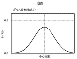
- FIG. 5 is a diagram showing a Gaussian distribution, and a general irradiance distribution of light such as a pinhole shows characteristics of the Gaussian distribution with respect to the optical axis. If the diffusion process K t of Equation 2 follows a Gaussian distribution G t (x, y), Equation 2 becomes Equation 7.
- FIG. 6 is a diagram showing the LoG distribution.
- the method for restoring the blurred image expressed by the convolution product is called deconvolution, and is effective for restoring the imaging blur in the camera.
- the restoration of the blurred image in the projector 1 will be described.
- the video signal to be photographed includes a diffusion process due to the defocus of the lens.
- the video signal is converted into an optical system, and then the diffusion process is performed by the lens.
- the corrected image by the image correcting unit 30 is set as I C, and as a result of the lens diffusion calculation K t in the optical system, an ideal image I 0 without blur is projected onto the screen. That is, these relationships are expressed as Equation 12.
- the resolution restoration unit 34 of the video correction unit 30 can reduce the blur due to the defocusing of the projected video 203 by performing the inverse diffusion process calculation K- t in advance on the original video I 0 (x, y). it can.
- the despreading process calculation K- t for an ideal image without blur is overcorrected, and thus a negative value is generated in the signal level. In order to deal with this negative value, correction by a gain ⁇ and an offset ⁇ is introduced as will be described later.
- FIG. 7A is a diagram illustrating a video signal correction method according to the first embodiment.
- the brightness level is displayed.
- the graph of the corrected video I C represents the luminance level calculated using Equation 13, and the graph of the projected video I S is the luminance level obtained by superimposing a Gaussian distribution (that is, PSF) assuming the blur ratio on the corrected video I C. Represents.
- PSF Gaussian distribution
- FIG. 7B is a diagram illustrating a state where blur occurs without correction for comparison.
- the graph of (a) shows the luminance distribution (luminance level) of the video 51 input to the LCD 22 in FIG. 4B. Since this image is not made correction in the image correction unit 30, equal to the input image I 0.
- the graph of (b) shows the luminance distribution (luminance value) of the blurred image 52 ′ displayed on the screen 2 in FIG. 4B.
- the luminance value on the screen 2 is measured by a surface luminance meter or the like.
- the input image 51 on the LCD 22 spreads in a Gaussian distribution in the projected image 52 ′ on the screen 2, and blur occurs.
- the correction image I C which is calculated using Equation 13 includes a negative value in the luminance level as shown in Figure 7A.
- the negative value of the video signal cannot be expressed by the light intensity. Therefore, the high dynamic range and the minus correction are expressed by introducing the correction of the gain ⁇ and the offset ⁇ as shown in Equation 14.
- the luminance level distribution on the vertical axis is moved to the positive side by the offset ⁇ so that the luminance level takes only a positive value.
- the gain is adjusted by ⁇ so as to match the original luminance level.
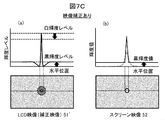
- FIG. 7C is a diagram illustrating the effect of offset and gain adjustment in correction.
- Graph (a) the video 51 is input to the LCD 22 ', that is, the luminance level of the corrected video I C.
- the black luminance level for expressing a negative value is raised by an offset ⁇ , and the white luminance level is adjusted by adjusting the gain ⁇ .
- the graph of (b) shows the luminance distribution (luminance value) of the video 52 (projected video I S ) projected on the screen 2. Blur on the screen is reduced by correction including despreading calculation. At this time, the introduction of offset and gain adjustment has the effect of increasing the black luminance value and obtaining an image with a high dynamic range.
- the blur amount calculation unit 33 obtains the blur amount as a standard deviation when the diffusion process follows a Gaussian distribution.
- the standard deviation is obtained by measuring the PSF on the optical axis with a surface luminance meter or the optical characteristics of the lens at the position where the focus shift occurs as shown in FIG. 4B, and performing linear interpolation according to the projection distance of each screen. You may approximate.
- the above is the method for reducing the image blur in the projector.
- the blur reduction function of this embodiment is added to the menu function of the projector.
- the menu function of the projector for example, adjustment of screen brightness, contrast, hue, keystone, input switching, and the like are provided for the user to select and set.
- FIG. 8A is a diagram showing an example of a blur reduction menu display.
- the name of this function is “blurring removal” 61 and several options are provided.
- the ideal value of gain ⁇ in equation 14 is a and the ideal value of offset ⁇ is b
- the option is “strong”
- the blur reduction function is activated (on), and the offset ⁇ at that time is set to the ideal value b.
- the gain ⁇ is 1 / (a + b).
- the blur reduction function is not operated (OFF).
- the user can execute the blur reduction function at a desired level according to the type of video and the projection environment.
- FIG. Brightness is a function for adjusting the brightness of the screen image, and the adjustment can be “brighter” or “darker”.
- this adjustment there are a method of adjusting (dimming) the luminance value of the light source and a method of adjusting the luminance level by video signal processing without changing the luminance of the light source.
- a method for adjusting the luminance level in the latter video signal processing will be described.
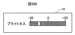
- FIG. 8B is a diagram showing an example of menu display for brightness adjustment.
- the name of this function is “Brightness” 62
- the brightness adjustment level is normally positive and negative, and can be adjusted stepwise from +30 to ⁇ 30 as an example.
- the luminance level of the video signal is changed.
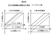
- ⁇ ′ represents the brightness adjustment level, which is set at the adjustment level in FIG. 8B.
- (A) is a case where the brightness is adjusted in the positive direction, that is, a direction in which the image is brightened
- (b) is a case where the brightness is adjusted in the negative direction, that is, a direction in which the image is darkened.
- (A) is a case where the brightness adjustment ⁇ ′ in the positive direction is interlocked, but the brightness adjustment and the blur reduction function are the same processing, so that ⁇ ′ and ⁇ are not applied twice. Use the larger value. That is, ⁇ is adopted when the offset value ⁇ is larger than the brightness adjustment level ⁇ ′, and ⁇ ′ is adopted when ⁇ ′ is larger than ⁇ .
- (B) is a case where it is linked with the brightness adjustment ⁇ ′ in the negative direction, but in order to execute the blur reduction function, the offset value ⁇ is preferentially adopted. In both cases (a) and (b), the offset value ⁇ is the lower limit of brightness adjustment.
- the brightness adjustment function and the brightness adjustment function linked with the blur reduction function described above are executed by the control unit of the projector by switching appropriately according to the user setting state for the menu function.
- the brightness adjustment has been described above as an example, but the same applies to, for example, image contrast adjustment, that is, input / output line inclination adjustment. That is, ⁇ ′ is adopted if the contrast adjustment level ⁇ ′ is greater than the gain value ⁇ of the present embodiment, and ⁇ is employed if the gain value ⁇ of the present embodiment is greater than the contrast adjustment level ⁇ ′. That is, the gain value ⁇ in this embodiment is the lower limit value of the contrast adjustment level.
- the configuration of the first embodiment it is possible to provide a projector that suitably reduces image blur due to lens focus shift.
- the configuration of a projector provided with resolution restoration processing by despreading calculation has been described.
- a configuration for improving the accuracy of the despreading calculation by matching the luminance level correction of the video signal by the despreading process calculation with the luminance value after applying the projection optical system, that is, the irradiation luminance value will be described.
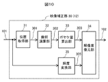
- FIG. 10 is a diagram illustrating a configuration of the image correcting unit 30 (12) of the projector in the second embodiment.
- the brightness conversion unit 35 is added to FIG. 2 of the first embodiment.
- the video correction unit 30 adds a luminance conversion unit 35 that converts the luminance level from the internal video signal 101 to the effective luminance signal 305. Yes.
- the resolution restoration unit 34 performs a despreading operation based on the blur amount 303 and the effective luminance signal 305.
- the luminance conversion unit 35 uses a conversion table in order to convert the luminance level from the internal video signal 101 to the effective luminance signal 305.
- This conversion table is created by, for example, the optical characteristics (for example, gamma characteristics) of the lamp 21 and the LCD panel 22, or is created by measuring all the R, G, and B gradations with a luminance radiation spectroluminometer or the like. .
- the conversion calculation from the internal video signal 101 to the irradiation luminance value is L.
- the resolution restoration unit 34 performs L inverse transformation on the internal video signal 101 in order to calculate the inverse diffusion calculation and the diffusion effect by the lens with the same characteristics. This is the above conversion table.
- an arithmetic expression obtained by adding an inverse transformation L ⁇ 1 of L to Expression 14 is Expression 15.
- the configuration of the second embodiment in a projector having a large difference between the internal video signal and the irradiation luminance due to the gamma characteristic or the like, it is possible to improve the accuracy of reducing the image blur due to the defocus of the lens.
- FIG. 11 is a diagram illustrating a configuration of the image correcting unit 30 (12) of the projector in the third embodiment.
- a kernel calculation unit 36 and a PSF map 37 are added instead of the blur amount calculation unit 33.
- the video correction unit 30 interpolates a PSF map 37 prepared in advance according to optical characteristics from the lens position and a convolution kernel 307 calculated from the PSF map 37. And a kernel calculation unit 36 that outputs the amount of blur 303.
- the resolution restoration unit 34 performs a despreading operation based on the internal video signal 101 and the blur amount 303.
- Example 1 a convex lens is taken as an example, and it is assumed that light parallel to the optical axis passes through the lens after passing through the lens. Therefore, blurring of the image is caused by a focus shift.
- an actual lens has an aberration, light does not collect at the focal point.
- the light may spread in a circular shape.
- Aberrations include Seidel's five aberrations and chromatic aberration, and tailing and color shift occur at positions away from the optical axis.
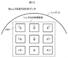
- the blur information that is, the spot diagram can be calculated or observed in advance from the lens design data. Therefore, the PSF at each lens position is mapped to the data table (PSF map 37).
- coefficients that can be converted into functions are mapped to data tables, and those with complex characteristics are mapped as convolution kernels.
- this information is held at pixel positions on all the lenses, the amount of data increases. For example, if there is symmetry, the symmetrical portion is deleted. Further, as shown in FIG. 12, data may be thinned out by linear interpolation from the intersections of the center and vertex and the horizontal axis, and the vertical axis and each side of the rectangle. If the chromatic aberration is large, PSF calculated for each wavelength of R, G, and B may be used.
- the PSF map 37 of FIG. 11 holds a data table to which PSF is mapped, and interpolates the thinned data by the kernel calculation unit 36. Further, the calculation of PSF in the resolution restoration unit 34 may use Formula 4, that is, Formula 6 on the premise of Fourier transform.
- the configuration of the third embodiment it is possible to improve the accuracy of reducing the image blur caused by the aberration of the lens.
- Embodiment 4 In Embodiment 4, the case where iris adjustment and lamp brightness adjustment are added to the configuration of each embodiment, and the case where dynamic control using a video histogram is performed will be described.
- FIG. 13 is a diagram illustrating a configuration of the image correcting unit 30 (12) of the projector in the fourth embodiment.
- a histogram acquisition unit 38 is further provided, and an iris adjustment and lamp brightness adjustment value 310 is input.
- the video correction unit 30 includes a position acquisition unit 31, a geometric calculation unit 32, a kernel calculation unit 36 that outputs a blur amount 303 using the PSF map 37, and luminance conversion that converts the internal video signal 101 into the effective luminance signal 305.
- a histogram acquisition unit 38 that acquires a histogram of the internal video signal 101 and outputs histogram information (frequency information) 308 is provided, and an iris adjustment value and a lamp luminance adjustment value 310 are input.
- the resolution restoration unit 34 receives the histogram information 308 of the video signal, the iris adjustment value, and the lamp luminance adjustment value 310, and performs a despreading operation.
- the resolution restoration unit 34 lowers the ⁇ value and the ⁇ value in Expression 15 because the irradiated image becomes dark when the F value is increased by iris adjustment or the light amount is decreased by lamp brightness adjustment. Accordingly, priority is given to widening the dynamic range so as not to cause blurring due to weakening of the contrast of the image. Conversely, when the F value is decreased by iris adjustment or the light amount is increased by luminance adjustment, the ⁇ value and ⁇ value in Expression 15 are increased, and the blur reduction function by despreading calculation is prioritized.
- the video is often a presentation video composed of characters and figures. Increase the value.
- the input video is uniformly distributed in the halftone, it is often a picture such as a photograph. Therefore, the overall contrast is prioritized by lowering the ⁇ and ⁇ values.
- the configuration of the fourth embodiment it is possible to effectively reduce image blur by dynamically setting parameters for despreading calculation using iris and lamp luminance adjustment and image histogram information.
- Example 5 describes a case where dynamic control by lens shift adjustment is performed in the configuration of each example.
- FIG. 14 is a diagram illustrating a configuration of the image correcting unit 30 (12) of the projector according to the fifth embodiment.
- the video display position information 311 by lens shift is further input.
- the video correction unit 30 is connected to the position acquisition unit 31, the geometric calculation unit 32, the PSF map 37, the kernel calculation unit 36 that inputs video display position information 311 by lens shift, and the effective luminance signal 305 from the internal video signal 101.
- the resolution restoration unit 34 receives the blur amount 303 and the effective luminance signal 305 and performs a despreading operation.
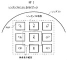
- Example 3 the blur information, that is, the spot diagram, is calculated or observed in advance based on the lens design data, and the PSF at each lens position is stored in the PSF map 37.
- a PSF map 37 including a lens shift range is prepared, and from the PSF at the intersection of the center and the vertex and the horizontal axis, and the vertical axis and the side, Linear interpolation is limited to the video display range.
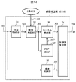
- FIG. 16 is a diagram illustrating a configuration of the image correcting unit 30 (12) of the projector in the sixth embodiment.
- a configuration in which a set value 312 for trapezoidal correction is input is input.
- the video correction unit 30 includes a position acquisition unit 31, a geometric calculation unit 32 that inputs a trapezoidal correction setting value 312, a kernel calculation unit 36 that outputs a blur amount 303 using the PSF map 37, and an internal video signal 101.
- the geometric calculation unit 32 calculates the distance ratio between the distance to the screen and the optical axis according to the trapezoidal correction setting value 312 together with the position where the image light beams intersect on the lens (reference numeral 302).
- the resolution restoration unit 34 receives the blur amount 303 and the effective luminance signal 305 and performs a despreading operation.
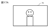
- FIG. 17A shows a case where keystone correction is not performed in the example of the internal video 71 of the projector 1.
- the same rectangular image as the input video signal 100 is displayed on the liquid crystal panel 22.
- FIG. 17B shows an image 72 obtained by projecting the internal image 71 of FIG. 17A onto the screen 2 by adding an elevation angle to the optical axis of the projector 1.
- the image 72 on the screen 2 has a shape in which the upper part spreads in a trapezoidal shape and extends upward, and so-called trapezoidal distortion occurs.
- the input signal processing unit 11 reduces the vertical direction of the input video signal 100 and geometrically converts it into a trapezoidal image opposite to the screen image.
- This correction is called keystone correction or keystone correction.
- the amount of keystone correction is set according to the magnitude of the keystone distortion.
- FIG. 18A shows a case where keystone correction is performed in the example of the internal image 73 of the projector 1.
- the trapezoidal region 73a is the original image
- the hatched region 73b at the end is no signal (black).
- 18B shows an image 74 obtained by projecting the image 73 of FIG. 18A onto the screen 2 by adding an elevation angle to the optical axis of the projector 1.
- the projected image 74 has a trapezoidal shape
- the hatched area 74b at the end is not visually recognized because there is no signal. Therefore, the original image is displayed on the rectangular area 74a on the screen 2.
- FIG. 19A is a ray diagram when the light is projected from the projector 1 onto the projection surface 2 perpendicular to the optical axis. When projected onto the vertical projection surface 2, it is assumed that light rays are suitably projected and no trapezoidal distortion occurs.
- FIG. 19B is a ray diagram when the projector 1 projects the optical axis with an elevation angle ⁇ . It can be seen that on the projection surface 2 ′ to which the elevation angle ⁇ is added, the distance between the light rays increases and the projection distance becomes longer toward the upper side.
- the geometric calculation unit 32 receives the trapezoidal correction set value 312 and calculates the distance to the screen 2 and the distance ratio between the optical axis, and using this, the pixels in the video signal pass through the lens 23 to the screen 2. When projected, the position 302 where the light rays intersect on the lens is calculated.
- the blur information that is, the spot diagram is calculated or observed in advance based on the lens design data, and the PSF at each lens position is stored in the PSF map 37.
- the kernel calculation unit 36 superimposes a PSF calculation of a focus shift due to a difference in distance to the screen 2 on the PSF, and performs linear interpolation, for example. According to the configuration of the sixth embodiment, it is possible to improve the accuracy of reducing the image blur that occurs due to the keystone correction.
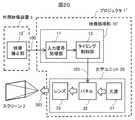
- the video correction unit 12 ′ is configured by an external video device 3 such as a PC. It can also be connected.
- the projector has been described as an example.
- the present invention is also effective in projection optical system equipment such as a head-mounted display and a head-up display having the same components in principle.
- 1 projector
- 2 Screen (projection surface)
- 3 External video device
- 10 Video processing unit
- 11 input signal processing unit
- 12 image correction unit
- 13 Timing control unit
- 20 Optical unit
- 21 Light source (lamp)
- 22 Liquid crystal panel (LCD)
- 23 Lens
- 31 Position acquisition unit
- 32 Geometric operation unit
- 33 blur amount calculation unit
- 34 Resolution restoration unit
- 35 luminance conversion unit
- 36 Kernel calculation unit
- 37 PSF map
- 38 Histogram acquisition unit.
Landscapes
- Engineering & Computer Science (AREA)
- Multimedia (AREA)
- Signal Processing (AREA)
- Physics & Mathematics (AREA)
- Geometry (AREA)
- Projection Apparatus (AREA)
- Controls And Circuits For Display Device (AREA)
- Transforming Electric Information Into Light Information (AREA)
- Control Of Indicators Other Than Cathode Ray Tubes (AREA)
Abstract
Description

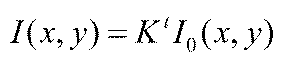
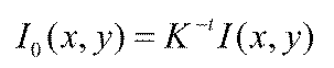







図7Aは、実施例1における映像信号の補正方法を説明する図である。この図では、映像補正部30への入力映像I0、映像補正部300からの補正映像IC、スクリーン2における投射映像ISについて、入力映像I0を点映像とした場合の水平位置での輝度レベルを表示している。


図17Aは、プロジェクタ1の内部映像71の例で台形補正を施さない場合を示す。後述する台形補正を施さない場合、液晶パネル22上においては入力映像信号100と同じ矩形状の映像となる。図17Bは、図17Aの内部映像71をプロジェクタ1の光軸に仰角を加えてスクリーン2へ投射した映像72を示す。この場合、スクリーン2上での映像72は、上部が台形状に広がり、また上方へと伸びた形状となり、いわゆる台形歪が発生している。
実施例6の構成によれば、台形補正に伴って発生する映像ボヤケの低減の精度を向上することができる。
2:スクリーン(投射面)、
3:外部映像装置、
10:映像処理部、
11:入力信号処理部、
12,30:映像補正部、
13:タイミング制御部、
20:光学ユニット、
21:光源(ランプ)、
22:液晶パネル(LCD)、
23:レンズ、
31:位置取得部、
32:幾何演算部、
33:ボヤケ量算出部、
34:解像度復元部、
35:輝度変換部、
36:カーネル算出部、
37:PSFマップ、
38:ヒストグラム取得部。
Claims (14)
- 映像を投射面に投射して表示するプロジェクタにおいて、
入力された映像信号に映像処理を行う映像処理部と、
前記映像処理部で映像処理した映像信号を入力して光学像を生成する映像表示素子と、
該映像表示素子で生成した光学像を前記投射面に投射する投射光学系と、を備え、
前記映像処理部は、前記投射光学系により投射される映像のボヤケを低減するための映像補正部を有し、該映像補正部では映像信号の黒輝度レベルを変更することを特徴とするプロジェクタ。 - 請求項1に記載のプロジェクタにおいて、
前記映像処理部には、さらに、映像のブライトネスを調整するために映像信号の黒輝度レベルを変更する機能を有し、
前記投射面に表示する映像の状態をユーザが設定するためのメニュー画面を表示し、ユーザ操作に基づいて前記映像処理部を制御する制御部を備え、
前記メニュー画面には、前記映像ボヤケを低減するために前記映像補正部の動作のオン・オフを設定する第1の設定項目と、前記ブライトネスを調整するために映像信号の黒輝度レベルを設定する第2の設定項目とが含まれており、
前記制御部は、前記第1の設定項目と前記第2の設定項目のユーザ設定状態に応じて、
前記第1の設定項目がオフの状態には、前記映像補正部の動作に伴う黒輝度レベルの変更は行わず、前記第2の設定項目に基づいて黒輝度レベルの変更する第1の状態と、
前記第1の設定項目がオンの状態には、前記映像補正部の動作に伴う黒輝度レベルの変更と前記第2の設定項目に基づく黒輝度レベルの変更とを連動させて映像信号の黒輝度レベルを変更する第2の状態と、
を切替えることを特徴とするプロジェクタ。 - 請求項1または2に記載のプロジェクタにおいて、
前記映像補正部は、
映像信号中の各画素が前記投射光学系により前記投射面へ投射される際に、前記投射面上に生じる映像のボヤケ量を算出するボヤケ量算出部と、
前記入力映像信号に対し、逆拡散過程演算を行うことで映像ボヤケを低減し解像度を復元する解像度復元部と、を備えることを特徴とするプロジェクタ。 - 請求項3に記載のプロジェクタにおいて、
前記解像度復元部は前記逆拡散過程演算を行う際、映像信号の負値を表現するため輝度レベルの0値すなわち黒輝度レベルに対しオフセットを加算するとともに、元の白輝度レベルに合わせるため輝度レベルのゲインを調整することを特徴とするプロジェクタ。 - 請求項3に記載のプロジェクタにおいて、
前記映像補正部は、前記映像表示素子及びこれに照明光を供給する光源の光学特性に基づき、入力する映像信号から実効輝度信号に輝度レベルを変換する輝度変換部を備え、
前記解像度復元部は、前記輝度変換部にて変換した実効輝度信号に対し、前記逆拡散過程演算を行うことを特徴とするプロジェクタ。 - 請求項3に記載のプロジェクタにおいて、
前記ボヤケ量算出部は、前記投射光学系を構成するレンズの収差により発生するボヤケ量をデータテーブルとして保持し、該データテーブルを用いてデータ補間することで各画素位置でのボヤケ量を算出することを特徴とするプロジェクタ。 - 請求項4に記載のプロジェクタにおいて、
前記解像度復元部は、前記投射光学系を構成するレンズのアイリス調整値や光源の輝度調整値を入力し、照射される光量が低下する場合には、前記映像信号の黒輝度レベルに対し加算するオフセットを減らすことを特徴とするプロジェクタ。 - 請求項4に記載のプロジェクタにおいて、
前記映像補正部は、入力する映像信号のヒストグラムを取得するヒストグラム取得部を備え、
前記解像度復元部は、前記ヒストグラム取得部からのヒストグラム情報に応じて、白黒の頻度もしくは高コントラストの2値の頻度が高い場合は、前記映像信号の黒輝度レベルに対し加算するオフセットを増やすことを特徴とするプロジェクタ。 - 請求項6に記載のプロジェクタにおいて、
前記ボヤケ量算出部は、前記レンズのレンズシフト調整による映像表示位置情報を入力し、前記データテーブルには、前記レンズシフト調整によりシフトする映像表示範囲を包含するように前記ボヤケ量のデータを保持することを特徴とするプロジェクタ。 - 請求項3に記載のプロジェクタにおいて、
前記映像補正部は、前記投射面へ投射される映像の台形歪を補正するための台形補正設定値を入力し、前記投射光学系において映像光線がレンズ上で交わる位置とともに前記台形補正設定値により前記投射面までの距離と光軸との距離比とを算出する幾何演算部を備え、
前記ボヤケ量算出部は、前記幾何演算部の算出結果に基づき前記ボヤケ量を算出することを特徴とするプロジェクタ。 - 映像を投射面に投射して表示する映像表示方法において、
入力された映像信号に映像処理を行う映像処理ステップと、
前記映像処理した映像信号を入力し映像表示素子にて光学像を生成する光学像生成ステップと、
前記生成した光学像を投射光学系により前記投射面に投射する投射ステップと、を備え、
前記映像処理ステップでは、前記投射光学系により投射される映像のボヤケを低減するため、映像信号の黒輝度レベルを変更する映像補正機能を有することを特徴とする映像表示方法。 - 請求項11に記載の映像表示方法において、
前記映像処理ステップでは、さらに、映像のブライトネスを調整するために映像信号の黒輝度レベルを変更する機能を有し、
前記投射面に表示する映像の状態をユーザが設定するためのメニュー画面を表示し、ユーザ操作に基づいて前記映像処理ステップを制御する制御ステップを備え、
前記メニュー画面には、前記映像ボヤケを低減するために前記映像補正機能の動作のオン・オフを設定する第1の設定項目と、前記ブライトネスを調整するために映像信号の黒輝度レベルを設定する第2の設定項目とが含まれており、
前記第1の設定項目と前記第2の設定項目のユーザ設定状態に応じて、
前記第1の設定項目がオフの状態には、前記映像補正機能の動作に伴う黒輝度レベルの変更は行わず、前記第2の設定項目に基づいて黒輝度レベルの変更する第1の状態と、
前記第1の設定項目がオンの状態には、前記映像補正機能の動作に伴う黒輝度レベルの変更と前記第2の設定項目に基づく黒輝度レベルの変更とを連動させて映像信号の黒輝度レベルを変更する第2の状態と、
を切替えることを特徴とする映像表示方法。 - 請求項11または12に記載の映像表示方法において、
前記映像補正機能では、
映像信号中の各画素が前記投射光学系により前記投射面へ投射される際に、前記投射面上に生じる映像のボヤケ量を算出するボヤケ量算出ステップと、
前記入力映像信号に対し、逆拡散過程演算を行うことで映像ボヤケを低減し解像度を復元する解像度復元ステップと、を備えることを特徴とする映像表示方法。 - 請求項13に記載の映像表示方法において、
前記解像度復元ステップでは前記逆拡散過程演算を行う際、映像信号の負値を表現するため輝度レベルの0値すなわち黒輝度レベルに対しオフセットを加算するとともに、元の白輝度レベルに合わせるため輝度レベルのゲインを調整することを特徴とする映像表示方法。
Priority Applications (4)
| Application Number | Priority Date | Filing Date | Title |
|---|---|---|---|
| PCT/JP2014/079758 WO2016075744A1 (ja) | 2014-11-10 | 2014-11-10 | プロジェクタ及び映像表示方法 |
| US15/522,619 US9955131B2 (en) | 2014-11-10 | 2014-11-10 | Projector and image display method |
| JP2016558463A JP6469130B2 (ja) | 2014-11-10 | 2014-11-10 | プロジェクタ及び映像表示方法 |
| CN201480083268.4A CN107079127B (zh) | 2014-11-10 | 2014-11-10 | 投影仪以及影像显示方法 |
Applications Claiming Priority (1)
| Application Number | Priority Date | Filing Date | Title |
|---|---|---|---|
| PCT/JP2014/079758 WO2016075744A1 (ja) | 2014-11-10 | 2014-11-10 | プロジェクタ及び映像表示方法 |
Publications (1)
| Publication Number | Publication Date |
|---|---|
| WO2016075744A1 true WO2016075744A1 (ja) | 2016-05-19 |
Family
ID=55953857
Family Applications (1)
| Application Number | Title | Priority Date | Filing Date |
|---|---|---|---|
| PCT/JP2014/079758 Ceased WO2016075744A1 (ja) | 2014-11-10 | 2014-11-10 | プロジェクタ及び映像表示方法 |
Country Status (4)
| Country | Link |
|---|---|
| US (1) | US9955131B2 (ja) |
| JP (1) | JP6469130B2 (ja) |
| CN (1) | CN107079127B (ja) |
| WO (1) | WO2016075744A1 (ja) |
Cited By (4)
| Publication number | Priority date | Publication date | Assignee | Title |
|---|---|---|---|---|
| JP2016197145A (ja) * | 2015-04-02 | 2016-11-24 | 株式会社東芝 | 画像処理装置および画像表示装置 |
| CN109901355A (zh) * | 2019-04-19 | 2019-06-18 | 深圳市当智科技有限公司 | 基于对比度加直方图的多元化投影仪自动对焦方法 |
| WO2019187511A1 (ja) * | 2018-03-29 | 2019-10-03 | ソニー株式会社 | 信号処理装置、情報処理方法、プログラム |
| JP2023151368A (ja) * | 2022-03-31 | 2023-10-16 | セイコーエプソン株式会社 | 頭部装着型表示装置 |
Families Citing this family (9)
| Publication number | Priority date | Publication date | Assignee | Title |
|---|---|---|---|---|
| JP5924020B2 (ja) * | 2012-02-16 | 2016-05-25 | セイコーエプソン株式会社 | プロジェクター、及び、プロジェクターの制御方法 |
| WO2016157671A1 (ja) * | 2015-03-27 | 2016-10-06 | ソニー株式会社 | 情報処理装置、情報処理方法、プログラム、及び画像表示装置 |
| JP6702600B2 (ja) * | 2016-02-03 | 2020-06-03 | Necディスプレイソリューションズ株式会社 | プロジェクター及びフォーカス調整方法 |
| WO2019172100A1 (ja) * | 2018-03-08 | 2019-09-12 | キヤノン株式会社 | 映像表示装置 |
| WO2019230108A1 (ja) * | 2018-05-28 | 2019-12-05 | ソニー株式会社 | 画像処理装置、画像処理方法 |
| US11394941B2 (en) * | 2018-05-28 | 2022-07-19 | Sony Corporation | Image processing device and image processing method |
| CN110996082B (zh) * | 2019-12-17 | 2021-11-09 | 成都极米科技股份有限公司 | 投影调节方法、装置、投影仪及可读存储介质 |
| JP7559803B2 (ja) * | 2022-06-09 | 2024-10-02 | セイコーエプソン株式会社 | 画像処理方法、プログラム、およびプロジェクター |
| CN115002434B (zh) * | 2022-08-02 | 2022-11-01 | 深圳市大屏影音技术有限公司 | 一种基于视觉分析的影音设备监管系统及方法 |
Citations (3)
| Publication number | Priority date | Publication date | Assignee | Title |
|---|---|---|---|---|
| JP2002366121A (ja) * | 2001-06-12 | 2002-12-20 | Matsushita Electric Ind Co Ltd | 映像表示装置および映像表示方法 |
| JP2005277969A (ja) * | 2004-03-25 | 2005-10-06 | Seiko Epson Corp | 画像処理装置、画像投射装置、方法、プログラムおよび記録媒体 |
| JP2009042838A (ja) * | 2007-08-06 | 2009-02-26 | Ricoh Co Ltd | 画像投影方法および画像投影装置 |
Family Cites Families (13)
| Publication number | Priority date | Publication date | Assignee | Title |
|---|---|---|---|---|
| JP3690402B2 (ja) * | 2003-03-28 | 2005-08-31 | セイコーエプソン株式会社 | 画像処理システム、プロジェクタ、プログラム、情報記憶媒体および画像処理方法 |
| JP5223452B2 (ja) * | 2008-05-20 | 2013-06-26 | 株式会社リコー | プロジェクタ及び投影画像形成方法及び車両用ヘッドアップディスプレイ装置 |
| JP5271631B2 (ja) * | 2008-08-07 | 2013-08-21 | Hoya株式会社 | 画像処理ユニット、撮像装置、合成画像作成プログラム |
| KR20100099008A (ko) * | 2009-03-02 | 2010-09-10 | 삼성전자주식회사 | 오토 포커싱 제어 방법 및 장치, 이를 이용한 디지털 촬영 장치 |
| JP5504806B2 (ja) | 2009-10-01 | 2014-05-28 | セイコーエプソン株式会社 | 画像処理装置、プロジェクター、画像処理方法およびプログラム |
| CN102129154A (zh) * | 2010-01-15 | 2011-07-20 | 上海三鑫科技发展有限公司 | 微型投影机及其调整方法 |
| CN101866096B (zh) * | 2010-05-04 | 2012-01-11 | 北京航空航天大学 | 一种基于模糊控制的多投影仪图像拼接自动边缘融合方法 |
| JP2012151670A (ja) * | 2011-01-19 | 2012-08-09 | Renesas Electronics Corp | 画像投影システム及び半導体集積回路 |
| CN102625043B (zh) * | 2011-01-25 | 2014-12-10 | 佳能株式会社 | 图像处理设备、成像设备和图像处理方法 |
| US8983221B2 (en) * | 2011-08-29 | 2015-03-17 | Panasonic Intellectual Property Management Co., Ltd. | Image processing apparatus, imaging apparatus, and image processing method |
| CN103974011B (zh) * | 2013-10-21 | 2017-07-11 | 浙江大学 | 一种投影图像模糊消除方法 |
| JP6327922B2 (ja) * | 2014-04-25 | 2018-05-23 | キヤノン株式会社 | 画像処理装置、画像処理方法、およびプログラム |
| JP6525718B2 (ja) * | 2015-05-11 | 2019-06-05 | キヤノン株式会社 | 画像処理装置、その制御方法、および制御プログラム |
-
2014
- 2014-11-10 JP JP2016558463A patent/JP6469130B2/ja active Active
- 2014-11-10 CN CN201480083268.4A patent/CN107079127B/zh active Active
- 2014-11-10 US US15/522,619 patent/US9955131B2/en active Active
- 2014-11-10 WO PCT/JP2014/079758 patent/WO2016075744A1/ja not_active Ceased
Patent Citations (3)
| Publication number | Priority date | Publication date | Assignee | Title |
|---|---|---|---|---|
| JP2002366121A (ja) * | 2001-06-12 | 2002-12-20 | Matsushita Electric Ind Co Ltd | 映像表示装置および映像表示方法 |
| JP2005277969A (ja) * | 2004-03-25 | 2005-10-06 | Seiko Epson Corp | 画像処理装置、画像投射装置、方法、プログラムおよび記録媒体 |
| JP2009042838A (ja) * | 2007-08-06 | 2009-02-26 | Ricoh Co Ltd | 画像投影方法および画像投影装置 |
Cited By (5)
| Publication number | Priority date | Publication date | Assignee | Title |
|---|---|---|---|---|
| JP2016197145A (ja) * | 2015-04-02 | 2016-11-24 | 株式会社東芝 | 画像処理装置および画像表示装置 |
| WO2019187511A1 (ja) * | 2018-03-29 | 2019-10-03 | ソニー株式会社 | 信号処理装置、情報処理方法、プログラム |
| JPWO2019187511A1 (ja) * | 2018-03-29 | 2021-04-15 | ソニー株式会社 | 信号処理装置、情報処理方法、プログラム |
| CN109901355A (zh) * | 2019-04-19 | 2019-06-18 | 深圳市当智科技有限公司 | 基于对比度加直方图的多元化投影仪自动对焦方法 |
| JP2023151368A (ja) * | 2022-03-31 | 2023-10-16 | セイコーエプソン株式会社 | 頭部装着型表示装置 |
Also Published As
| Publication number | Publication date |
|---|---|
| CN107079127A (zh) | 2017-08-18 |
| JPWO2016075744A1 (ja) | 2017-09-28 |
| US20170318270A1 (en) | 2017-11-02 |
| JP6469130B2 (ja) | 2019-02-13 |
| US9955131B2 (en) | 2018-04-24 |
| CN107079127B (zh) | 2019-11-29 |
Similar Documents
| Publication | Publication Date | Title |
|---|---|---|
| JP6469130B2 (ja) | プロジェクタ及び映像表示方法 | |
| JP3735158B2 (ja) | 画像投影システム、画像処理装置 | |
| US7529424B2 (en) | Correction of optical distortion by image processing | |
| CN103283214B (zh) | 摄像机、畸变校正装置以及畸变校正方法 | |
| RU2707066C1 (ru) | Устройство обработки изображения, устройство создания изображения, их способы управления и программа | |
| JP3908255B2 (ja) | 画像投影システム | |
| CN103200409B (zh) | 多投影仪显示系统的颜色校正方法 | |
| JP2012151670A (ja) | 画像投影システム及び半導体集積回路 | |
| WO2005002240A1 (ja) | 表示特性補正データの算出方法、表示特性補正データの算出プログラム、表示特性補正データの算出装置 | |
| JP2015097350A (ja) | 画像処理装置およびマルチプロジェクションシステム | |
| CN107197134B (zh) | 一种用于多个鱼眼镜头的图像的曝光调整方法和装置 | |
| JP6371092B2 (ja) | 映像処理装置及びそれを用いたプロジェクタ装置 | |
| JP2003032580A (ja) | プロジェクタによって投写される画像の画像処理 | |
| WO2018159162A1 (ja) | 画像処理装置およびその制御方法及びプログラム | |
| CN104956661A (zh) | 图像拾取装置、图像处理装置、图像处理方法和非暂时性计算机可读存储介质 | |
| US20050162620A1 (en) | Image processing apparatus | |
| JP2017156581A (ja) | 投影装置及びその制御方法 | |
| TWI703868B (zh) | 投影亮度和對比的自動調整系統及方法 | |
| JP6794983B2 (ja) | 情報処理装置、情報処理方法、プログラム、及び画像表示装置 | |
| JP2020191034A (ja) | 画像処理装置、撮像装置、レンズ装置、画像処理システム、画像処理方法、および、プログラム | |
| US10868953B2 (en) | Image processing device capable of notifying an effect of emphasizing a subject before performing imaging, control method thereof, and medium | |
| JP2005354680A (ja) | 画像投影システム | |
| US20170339381A1 (en) | Image processing apparatus and image processing method | |
| JP2004032665A (ja) | 画像投影システム | |
| US8545025B2 (en) | Image processing apparatus, projector, image processing method, and program |
Legal Events
| Date | Code | Title | Description |
|---|---|---|---|
| 121 | Ep: the epo has been informed by wipo that ep was designated in this application |
Ref document number: 14905939 Country of ref document: EP Kind code of ref document: A1 |
|
| ENP | Entry into the national phase |
Ref document number: 2016558463 Country of ref document: JP Kind code of ref document: A |
|
| WWE | Wipo information: entry into national phase |
Ref document number: 15522619 Country of ref document: US |
|
| NENP | Non-entry into the national phase |
Ref country code: DE |
|
| 122 | Ep: pct application non-entry in european phase |
Ref document number: 14905939 Country of ref document: EP Kind code of ref document: A1 |