WO2016072025A1 - 加振ユニット、ターゲット供給装置および極端紫外光生成装置 - Google Patents
加振ユニット、ターゲット供給装置および極端紫外光生成装置 Download PDFInfo
- Publication number
- WO2016072025A1 WO2016072025A1 PCT/JP2014/079625 JP2014079625W WO2016072025A1 WO 2016072025 A1 WO2016072025 A1 WO 2016072025A1 JP 2014079625 W JP2014079625 W JP 2014079625W WO 2016072025 A1 WO2016072025 A1 WO 2016072025A1
- Authority
- WO
- WIPO (PCT)
- Prior art keywords
- vibration
- target
- vibration transmission
- excitation
- supply device
- Prior art date
- Legal status (The legal status is an assumption and is not a legal conclusion. Google has not performed a legal analysis and makes no representation as to the accuracy of the status listed.)
- Ceased
Links
Images









Classifications
-
- H—ELECTRICITY
- H05—ELECTRIC TECHNIQUES NOT OTHERWISE PROVIDED FOR
- H05G—X-RAY TECHNIQUE
- H05G2/00—Apparatus or processes specially adapted for producing X-rays, not involving X-ray tubes, e.g. involving generation of a plasma
- H05G2/001—Production of X-ray radiation generated from plasma
- H05G2/002—Supply of the plasma generating material
- H05G2/0023—Constructional details of the ejection system
Definitions
- the present disclosure relates to an excitation unit, a target supply device, and an extreme ultraviolet light generation device that irradiates laser light to generate extreme ultraviolet (EUV) light.
- EUV extreme ultraviolet
- the EUV light generation apparatus includes an LPP (Laser Produced Plasma) system using plasma generated by irradiating a target material with laser light, and a DPP (Discharge Produced Plasma) using plasma generated by discharge.
- LPP Laser Produced Plasma
- DPP discharge Produced Plasma
- Three types of devices have been proposed: a device of the system and a device of SR (Synchrotron Radiation) method using orbital radiation.
- An excitation unit is an excitation unit (310, 320) that applies vibration to a target material (271) supplied into a target channel (FL), and the target channel is disposed inside the excitation unit (310, 320).
- the vibration transmission rate of the vibration transmission member may be smaller than the vibration attenuation rate of the first member.
- a target supply device includes a first member that includes a target flow path therein, a vibration transmission member that contacts the first member, an electrical contact from the outside that contacts the vibration transmission member, and An excitation unit including a piezoelectric member that vibrates in response to a signal, and the vibration attenuation factor of the vibration transmission member may be smaller than the vibration attenuation factor of the first member.
- a target supply device includes a first member including a target flow path therein, a vibration transmission member that contacts the first member, a contact that contacts the vibration transmission member, and An excitation unit including a piezoelectric member that vibrates in response to an electrical signal, and a contact shape between the first member and the vibration transmission member is a concave shape (313) that brings the contact position closer to the target channel. , 343, 363, 373, 391, 392, 393, 395).
- a target supply device includes a first member (265, 331) including a target flow channel therein and a second member (260) that stores a target material supplied to the target flow channel. ) And a vibration transmission member that contacts the first member, and a piezoelectric member that contacts the vibration transmission member and vibrates in response to an electric signal from the outside, and the first member
- the contact area between the second member and the target material may be smaller than the contact area between the second member and the target material.
- An extreme ultraviolet light generation device includes a chamber, any one of the target supply devices that supply the target material into the chamber, and the target material supplied into the chamber. You may provide the laser apparatus which irradiates a laser beam, and the collector mirror which condenses and outputs the extreme ultraviolet light radiated
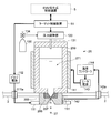
- FIG. 1 is a diagram schematically showing a configuration of an exemplary LPP type EUV light generation system.
- FIG. 2 is a schematic diagram illustrating an example of a target supply device including the target supply unit illustrated in FIG. 1.
- FIG. 3 is a diagram illustrating a schematic configuration when the nozzle member, the nozzle holder, and the vibration unit illustrated in FIG. 2 are viewed from below.
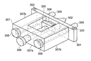
- FIG. 4 is a perspective view showing an example of the vibration unit shown in FIG.
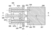
- FIG. 5 is a horizontal sectional view of the vibration unit shown in FIG.
- FIG. 6 is a vertical sectional view of the vibration unit shown in FIG. FIG.
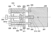
- FIG. 7 is a horizontal sectional view illustrating a schematic configuration example of the vibration unit according to the first embodiment.
- FIG. 8 is a horizontal cross-sectional view illustrating a schematic configuration example of the vibration unit according to the second embodiment.
- FIG. 9 is a horizontal cross-sectional view illustrating an example of attachment of the vibration unit according to the third embodiment.
- FIG. 10 is a vertical sectional view of the mounting example shown in FIG.
- FIG. 11 is a diagram illustrating an example of a material that can be selected as a material for the vibration transmitting member in the third embodiment.
- FIG. 12 is a cross-sectional view illustrating a schematic shape of the vibration pin according to the first modification of the vibration pin.
- FIG. 13 is a cross-sectional view illustrating a schematic shape of a vibration pin according to a second modification of the vibration pin.
- FIG. 14 is a cross-sectional view illustrating a schematic shape of a vibration pin according to a third modification of the vibration pin.
- FIG. 15 is a cross-sectional view illustrating a schematic shape of a vibration pin according to a fourth modification of the vibration pin.
- FIG. 16 is a cross-sectional view illustrating a schematic shape according to a first modification of the contact form between the vibration pin and the vibration hole.
- FIG. 17 is a cross-sectional view illustrating a schematic shape according to a second modification of the contact form between the vibration pin and the vibration hole.
- FIG. 18 is a cross-sectional view illustrating a schematic shape according to a third modified example of the contact form between the vibration pin and the vibration hole.
- FIG. 18 is a cross-sectional view illustrating a schematic shape according to a fourth modification of the contact form between the vibration pin and the vibration hole.
- Outline Embodiments of the present disclosure relate to an excitation unit used in a target supply device for supplying a target material for EUV light generation in the form of a droplet, and a target supply device and an EUV light generation device including the vibration unit. It may be. More specifically, the embodiment relates to an excitation unit that applies vibration for changing the target material jetted from the nozzle into a droplet form to the tip of the nozzle, and a target supply apparatus and EUV light including the vibration unit. It may relate to a generation device. However, the present disclosure is not limited to these matters, and may be related to all matters for changing the jetted liquid into a droplet form.
- FIG. 1 schematically shows a configuration of an exemplary LPP type EUV light generation system.
- the EUV light generation apparatus 1 may be used together with at least one laser apparatus 3.
- a system including the EUV light generation apparatus 1 and the laser apparatus 3 is referred to as an EUV light generation system 11.
- the EUV light generation apparatus 1 may include a chamber 2 and a target supply unit 26.
- the chamber 2 may be sealable.
- the target supply unit 26 may be attached so as to penetrate the wall of the chamber 2, for example.
- the material of the target substance supplied from the target supply unit 26 may include, but is not limited to, tin, terbium, gadolinium, lithium, xenon, or a combination of any two or more thereof.
- the wall of the chamber 2 may be provided with at least one through hole.
- a window 21 may be provided in the through hole, and the pulse laser beam 32 output from the laser device 3 may pass through the window 21.
- an EUV collector mirror 23 having a spheroidal reflecting surface may be disposed.
- the EUV collector mirror 23 may have first and second focal points.
- On the surface of the EUV collector mirror 23, for example, a multilayer reflective film in which molybdenum and silicon are alternately laminated may be formed.
- the EUV collector mirror 23 is preferably arranged such that, for example, the first focal point thereof is located in the plasma generation region 25 and the second focal point thereof is located at the intermediate focal point (IF) 292.
- a through hole 24 may be provided at the center of the EUV collector mirror 23, and the pulse laser beam 33 may pass through the through hole 24.
- the EUV light generation apparatus 1 may include an EUV light generation control apparatus 5, a target sensor 4, and the like.
- the target sensor 4 may have an imaging function and may be configured to detect the presence, trajectory, position, speed, and the like of the target 27.
- the EUV light generation apparatus 1 may include a connection unit 29 that allows the inside of the chamber 2 and the inside of the exposure apparatus 6 to communicate with each other.
- a wall 291 in which an aperture 293 is formed may be provided inside the connection portion 29.
- the wall 291 may be arranged such that its aperture 293 is located at the second focal position of the EUV collector mirror 23.
- the EUV light generation apparatus 1 may include a laser beam traveling direction control unit 34, a laser beam focusing mirror 22, a target recovery unit 28 for recovering the target 27, and the like.
- the laser beam traveling direction control unit 34 may include an optical element for defining the traveling direction of the laser beam and an actuator for adjusting the position, posture, and the like of the optical element.
- the pulsed laser beam 31 output from the laser device 3 passes through the window 21 as the pulsed laser beam 32 through the laser beam traveling direction control unit 34 and enters the chamber 2. May be.
- the pulse laser beam 32 may travel along the at least one laser beam path into the chamber 2, be reflected by the laser beam collector mirror 22, and irradiate at least one target 27 as the pulse laser beam 33.
- the target supply unit 26 may be configured to output the target 27 toward the plasma generation region 25 inside the chamber 2.
- the target 27 may be irradiated with at least one pulse included in the pulse laser beam 33.
- the target 27 irradiated with the pulsed laser light is turned into plasma, and radiation light 251 can be emitted from the plasma.
- the EUV light 252 included in the radiation light 251 may be selectively reflected by the EUV collector mirror 23.
- the EUV light 252 reflected by the EUV collector mirror 23 may be condensed at the intermediate condensing point 292 and output to the exposure apparatus 6.
- a single target 27 may be irradiated with a plurality of pulses included in the pulse laser beam 33.
- the EUV light generation control device 5 may be configured to control the entire EUV light generation system 11.
- the EUV light generation controller 5 may be configured to process image data of the target 27 imaged by the target sensor 4. Further, the EUV light generation control device 5 may be configured to control the timing at which the target 27 is output, the output direction of the target 27, and the like. Further, the EUV light generation control device 5 may be configured to control, for example, the oscillation timing of the laser device 3, the traveling direction of the pulse laser light 32, the condensing position of the pulse laser light 33, and the like.
- the various controls described above are merely examples, and other controls may be added as necessary.
- the “droplet” may be a molten droplet of the target material.
- the shape may be substantially spherical.
- the “plasma generation region” may be a three-dimensional space preset as a space where plasma is generated.
- FIG. 2 is a schematic diagram illustrating an example of a target supply device including the target supply unit illustrated in FIG.
- FIG. 3 is a diagram illustrating a schematic configuration when the nozzle member, the nozzle holder, and the vibration unit illustrated in FIG. 2 are viewed from the output direction of the target.
- the target supply device includes a tank unit (first or second member) 260, a nozzle member 266, a pressure regulator 120, a temperature controller 144, a target control device 51, and an excitation unit. 111 and a piezoelectric power source 112 may be included.
- tin (Sn) as the target material 271 may be stored.
- the material of the tank part 260 may be a material having low reactivity with tin.
- the material having a low reactivity with tin may be, for example, molybdenum (Mo).
- the nozzle member 266 may have a nozzle hole 267 having a hole diameter of 3 to 6 ⁇ m.
- the material of the nozzle member 266 may be a material having low reactivity with tin (for example, Mo).
- the nozzle member 266 may be fixed to the bottom of the tank portion 260 by a nozzle holder (first member) 265.
- the material of the nozzle holder 265 may be a material having low reactivity with tin (for example, Mo). Surface sealing may be performed between the nozzle member 266 and the nozzle holder 265 and between the tank portion 260 and the nozzle member 266, respectively.
- An inert gas cylinder 130 may be connected to the pressure regulator 120.
- a valve 134 that can be controlled by the pressure regulator 120 may be provided on the gas pipe between the cylinder 130 and the pressure regulator 120.
- the pressure regulator 120 may be communicated with the inside of the tank portion 260 via the introduction pipe 131.
- the pressure regulator 120 may introduce the inert gas supplied from the cylinder 130 into the tank unit 260 through the introduction pipe 131.
- the temperature controller 144 may be connected to the temperature sensor 142 and the heater power supply 143.
- the temperature sensor 142 may be arranged to measure the temperature of the tank unit 260 or the nozzle holder 265.
- the heater power supply 143 may be electrically connected to the heater 141.
- the heater power supply 143 may supply current to the heater 141 in accordance with control from the temperature controller 144.
- the heater 141 may be arranged so as to heat the target material 271 in the tank unit 260.
- the heater 141 may be disposed on the outer surface of the tank unit 260.
- the temperature sensor 142 and the temperature controller 144 may be electrically connected via an introduction terminal 142 a provided on the partition wall of the chamber 2.
- the introduction terminal 142 a may electrically insulate the connection line between the temperature sensor 142 and the temperature controller 144 from the chamber 2 while maintaining the airtightness of the chamber 2.
- the piezo power supply 112 may be connected to the target control device 51 and the vibration unit 111.
- the piezo power supply 112 and the vibration unit 111 may be electrically connected via an introduction terminal 111 a provided on the partition wall of the chamber 2.
- the introduction terminal 111a may electrically insulate the connection line between the piezoelectric power source 112 and the vibration unit 111 from the chamber 2 while maintaining the airtightness of the chamber 2.
- the vibration unit 111 may be provided on the side surface of the nozzle holder 265.
- the vibration units 111 may be arranged so as to have a line-symmetric relationship with respect to an axis passing through the center of the nozzle hole 267. Details of each excitation unit 111 will be described later.
- the target control device 51 may be connected to the vibration unit 111, the temperature controller 144, the pressure regulator 120, and the EUV light generation control device 5.
- the inside of the tank unit 260 may be communicated with the nozzle hole 267 via a target channel provided at the bottom of the tank unit 260.
- a filter (not shown) for filtering the circulating target material 271 may be disposed in the target channel.
- the target control device 51 shown in FIG. 2 may execute the following processing when a droplet output preparation signal is input from the EUV light generation control device 5 or the control unit of the external device.
- the target control device 51 may first control the temperature controller 144 so that the target material 271 in the tank portion 260 has a temperature equal to or higher than the melting point.
- the temperature controller 144 may drive the heater power supply 143 so that the detected value of the temperature sensor 142 is equal to or higher than a predetermined temperature.
- the predetermined temperature may be a temperature equal to or higher than the melting point of tin (temperature 232 ° C.).
- the predetermined temperature may be a temperature range.
- the temperature range may be 240 ° C. to 290 ° C., for example.
- the target control device 51 may determine whether or not the detected value of the temperature sensor 142 is maintained at a predetermined temperature or higher for a predetermined time. When the predetermined temperature or higher is maintained for a predetermined time, the target control device 51 may notify the EUV light generation control device 5 or the control unit of the external device that the preparation for droplet output has been completed. Thereafter, the target control device 51 may stand by until a droplet output signal for requesting the output of the droplet 27 is input.
- the target control device 51 may control the pressure regulator 120 to increase the pressure in the tank unit 260 to a predetermined pressure.
- the predetermined pressure may be, for example, about 10 MPa (megapascal).
- the target control device 51 may control the pressure regulator 120 to maintain the pressure in the tank unit 260 at a predetermined pressure.
- the jet of the target material 271 may be output from the nozzle hole 267.
- the target control device 51 may control the piezo power supply 112 so that the jet of the target material 271 discharged from the nozzle hole 267 changes to a droplet having a predetermined size and a predetermined cycle.
- a voltage having a predetermined waveform may be applied from the piezoelectric power source 112 to the excitation unit 111.
- the vibration generated in the vibration unit 111 to which a voltage having a predetermined waveform is applied may be transmitted to the target material 271 via the nozzle holder 265, the nozzle member 266, and the tank unit 260.
- the jet of the target material 271 may be divided and changed into droplets having a predetermined size and a predetermined cycle.
- FIG. 4 is a perspective view showing an example of the vibration unit shown in FIG. 5 is a cross-sectional view of a plane including the central axes of the two first bolts 308 of the vibration unit shown in FIG. 4, and FIG. 6 is a vertical axis perpendicular to the cross section of FIG. It is sectional drawing in the surface containing. 5 shows an example of the cross-sectional structure of the BB plane shown in FIG. 6, and FIG. 6 shows an example of the cross-sectional structure of the AA plane shown in FIG.
- 4 to 6 includes two first bolts 308, a second bolt 306, a pressurizing frame 307, a pressing member 305, a piezo element 304, and a vibration transmitting member 301. May be included.
- the pressurizing frame 307 may be a frame member of the vibration unit 300.
- the pressurizing frame 307 may include one arm portion 307b located on both sides and a central beam portion 307a that connects the other arm portion 307b.
- the vibration transmitting member 301 may be disposed between the pressurizing frame 307 and the nozzle holder 265. At the center of the vibration transmitting member 301, a truncated cone-shaped protrusion 302 having a narrow tip side may be provided. The tip of the protrusion 302 may contact the side surface of the nozzle holder 265. The contact area between the tip of the protrusion 302 and the side surface of the nozzle holder 265 may be smaller than the area of any one surface of the piezo element 304.
- the two first bolts 308 may fix the pressurizing frame 307 and the vibration transmitting member 301 to the side surface of the nozzle holder 265. Therefore, a screw portion may be formed at the tip 309 of the shaft portion of the first bolt 308. Two screw holes into which the tips 309 of the shaft portions of the two first bolts 308 are screwed may be provided on the side surface of the nozzle holder 265.
- the two arm portions 307b and the vibration transmitting member 301 in the pressurizing frame 307 may be provided with two through holes into which the two first bolts 308 are respectively inserted.
- the second bolt 306 may be an adjusting member that adjusts the pressure for pressing the piezo element 304 and the vibration transmitting member 301 against the nozzle holder 265. Therefore, a screw hole for screwing the second bolt 306 may be provided in the central beam portion 307 a of the pressurizing frame 307.
- the vibration transmitting member 301 may be urged toward the nozzle holder 302 by the second bolt 306 screwed into the pressurizing frame 307.
- a piezo element 304 and a pressing member 305 may be disposed between the second bolt 306 and the vibration transmission member 301.
- the second bolt 306 may press the protrusion 302 of the vibration transmission member 301 against the nozzle holder 265 while pressing the piezo element 304 against the vibration transmission member 301 via the pressing member 305.
- the piezo element 304 may be a piezoelectric member that vibrates in response to an external electric signal.
- the piezo element 304 may be connected to the piezo power source 112 (see FIG. 2) by a wiring (not shown).
- the piezo element 304 may be a piezoelectric element using lead zirconate titanate.
- the vibration transmission member 301 may be provided with a cooling water pipe 303.
- the cooling water pipe 303 may be connected to a cooling water temperature adjusting device (not shown).
- the mounting position of the vibration unit 300 is not limited to the side surface of the nozzle holder 265.
- the vibration unit 300 may be attached to the side surface of the tank unit 260.
- the vibration unit 300 may be attached at any location as long as the target material 271 existing in the target flow path FL from the tank portion 260 to the nozzle hole 267 can be vibrated.
- the pressurizing force that presses the protrusion 302 of the vibration transmitting member 301 against the nozzle holder 265, and the piezo element 304 by the pressing member 305 and the vibration transmitting member 301.
- the pressurization pressure (the pressurization to the piezo element 304) may be applied by the second bolt 306.
- the vibration transmitting member is formed by screwing the first bolt 308 in a state of being inserted into the through hole of the arm portion 307 b and the vibration transmitting member 301 in the pressurizing frame 307 into the screw hole of the nozzle holder 265.
- a pressurizing force that presses 301 against the nozzle holder 265 may be applied to both side ends of the vibration transmitting member 301.
- the pressurizing force that presses the protruding portion 302 against the nozzle holder 265 is near the center of the vibration transmitting member 301 via the pressing member 305 and the piezoelectric element 304. May be given.
- a pressurizing force that sandwiches the piezo element 304 between the pressing member 305 and the vibration transmitting member 301 may be applied.
- the pressurization applied by the second bolt 306 may be a pressurization that presses the protrusion 302 of the vibration transmitting member 301 against the nozzle holder 265.
- the aforementioned pressurization can be adjusted by adjusting the screwing torque of the first bolt 308 and the second bolt 306. At this time, the screwing torques of the first bolt 308 and the second bolt 306 are adjusted so that the vibration generated in the piezo element 304 reaches the target material 271 in the tank portion 260 via the protrusion 302 of the vibration transmitting member 301. May be.
- the piezo element 304 may generate vibration by expanding and contracting based on a voltage having a predetermined waveform applied from the piezo power source 112.
- the generated vibration may be transmitted to the target material 271 in the target flow path FL via the projection 302 of the vibration transmitting member 301, the nozzle holder 265, the nozzle member 266, the tank portion 260, and the like.
- the jet of the target material 271 discharged from the nozzle hole 267 can be changed into droplets having a predetermined size and a predetermined cycle.
- the vibration transmission member 301 may be cooled with cooling water flowing through the cooling water pipe 303. Thereby, the temperature of the piezo element 304 may be suppressed to be equal to or higher than the Curie point due to heat from the heater 141 transmitted via the tank unit 260, the nozzle holder 265, and the like.
- the Curie point of the piezo element 304 may be in the range of 150 ° C. to 350 ° C.
- the volume of the target 27 output in a droplet shape may be reduced.
- the hole diameter of the nozzle hole 267 (hereinafter referred to as nozzle diameter) may be reduced.
- the nozzle diameter is reduced in the target supply device including the vibration unit 300, there is a possibility that the droplet generation cycle becomes unstable. This is considered to be because when the nozzle diameter is reduced, the vibration frequency to be transmitted to the target material 271 increases in order to stably generate droplets.
- the vibration frequency necessary for stable droplet generation when the nozzle diameter is ⁇ 10 ⁇ m is 1.5 MHz (megahertz)
- the vibration frequency necessary when the nozzle diameter is ⁇ 6 ⁇ m can be 3 MHz.
- the vibration with a frequency of 1.5 MHz can be transmitted to the target material 271 relatively well.
- the high frequency vibration required when the nozzle diameter is reduced cannot be transmitted to the target material 271 with sufficient amplitude.
- the generation of droplets is easily affected by disturbance, and as a result, the generation cycle of droplets can be unstable.
- an excitation unit capable of transmitting relatively high-frequency vibrations with sufficient amplitude is exemplified.
- a material having a relatively low vibration attenuation factor may be used for a member that is located on a path for transmitting the generated vibration to the target material 271 and that does not contact the target material 271.
- the material having a relatively low vibration attenuation rate is a member located on the path for transmitting the generated vibration to the target material 271 and having a lower vibration attenuation rate than the material of the member in contact with the target material 271.
- the nozzle holder 265, the nozzle member 266, and the tank unit 260 may be used as members that are located on a path that transmits the generated vibration to the target material 271 and that are in contact with the target material 271.
- the member located on the path for transmitting the generated vibration to the target material 271 and not in contact with the target material 271 may be, for example, a vibration transmission member.
- FIG. 7 is a cross-sectional view illustrating a schematic configuration example of the vibration unit according to the first embodiment. 7 shows a structural example of a cross section corresponding to FIG. Moreover, in the following description, about the structure similar to the vibration unit 300, the same code
- the vibration transmission member 301 may be replaced with a vibration transmission member 311 in the same configuration as the vibration unit 300.
- the vibration transmission member 311 may have the same configuration as that of the vibration transmission member 301, and the protrusion 302 may be replaced with the vibration pin 312.
- the vibration pin 312 may be integrated with another configuration of the vibration transmission member 311 or may be a separate member.
- the excitation pin 312 may have a cylindrical shape.
- the circular cross-sectional area of the excitation pin 312 may be smaller than the area of any one surface of the piezo element 304.
- the vibration pin 312 may be formed of a material having a vibration attenuation rate lower than that of the material of the nozzle holder 265, the tank unit 260, or the like.
- the logarithmic vibration damping factor may be 0.03.
- stainless steel having a logarithmic vibration attenuation factor of 0.01 ( ⁇ 0.03) may be used as the material of the excitation pin 312.
- the material of the other configuration of the vibration transmitting member 311 may be formed of a material having a vibration damping rate lower than that of the nozzle holder 265, the tank portion 260, and the like.
- a vibration hole 313 may be provided in a contact portion of the nozzle holder 265 with the vibration transmission member 311.
- the tip of the vibration pin 312 may contact the bottom of the vibration hole 313.
- the excitation hole 313 may have a concave shape from the side surface of the nozzle holder 265 toward the target flow path FL. That is, the excitation hole 313 may have a shape that brings the contact position between the excitation pin 312 and the nozzle holder 265 closer to the target flow path FL.
- the shortest distance between the contact surface (that is, the bottom of the excitation hole 313) and the target flow path FL may be 2 to 5 mm, for example. More preferably, the shortest distance may be 3 mm.
- the opening shape of the excitation hole 312 is not limited to a circle, and various shapes such as a triangle and a rectangle can be applied. Further, the excitation hole 312 may be a groove formed on one side surface of the nozzle holder 265.
- the mounting position of the vibration unit 310 is not limited to the side surface of the nozzle holder 265.
- the vibration unit 310 may be attached to the side surface of the tank unit 260.
- the excitation hole 313 may also be formed on the side surface of the tank portion 260. That is, the vibration unit 310 may be attached to any location as long as the vibration can be applied to the target material 271 existing in the target flow path FL.
- the vibration hole 313 may be formed corresponding to the mounting position of the vibration unit 310.
- vibration generated in the piezo element 304 is caused by vibration pins 312 and nozzle holders of the vibration transmission member 311. It may be transmitted to the target material 271 in the target flow path FL via H.265, the nozzle member 266, the tank portion 260, and the like. Thereby, the jet of the target material 271 ejected from the nozzle hole 267 may be divided and changed into droplets having a predetermined size and a predetermined cycle.
- the nozzle holder 265, the tank unit 260, and the like are added to the vibration transmission member 311 that is a part of the transmission path to the target material 271 of the generated vibration.
- a material having a vibration damping rate lower than the vibration damping rate may be used. Thereby, vibration generated in the piezo element 304 can be efficiently transmitted to the target material 271 in the target flow path FL.
- the vibration transmission member 311 vibrates more than the vibration transmission member 311 in the vibration transmission path from the piezo element 304 to the target material 271.
- a section with a large attenuation rate can be shortened. Thereby, vibrations can be transmitted to the target material 271 more efficiently.
- the excitation pin 312 when the excitation pin 312 is integrated with another configuration of the vibration transmission member 311, the number of components on the vibration transmission path can be reduced, so that vibration attenuation occurring at the component joint portion can be reduced. Thereby, vibrations can be transmitted to the target material 271 more efficiently.
- the temperature of the first bolt 308 in the vibration unit 300 can also rise due to the heat.
- the first bolt 308 can be at substantially the same temperature as the tank portion 260 and the like.
- the vibration transmission member 301 is cooled by the cooling water flowing through the cooling water flow path 303, the temperature can be several tens of degrees.
- the vibration unit 300 assembled at room temperature is heated in a state where it is assembled to the nozzle holder 265, the tank unit 260, etc.
- the first bolt 308 expands in the extending direction due to heat.
- the pressurizing pressure that presses the vibration transmitting member 301 against the nozzle holder 265, the tank portion 260, and the like, and the pressurizing pressure that sandwiches the piezo element 304 may be reduced or fluctuated.
- the first bolt 308 that rises in temperature extends in the extending direction due to thermal expansion, whereas the thermal expansion of the vibration transmission member 301 and the pressurizing frame 307 that are cooled can be suppressed.
- the force with which the first bolt 308 presses the pressurizing frame 307 and the vibration transmitting member 301 against the nozzle holder 265, the tank portion 260, and the like may be reduced.
- the pressurization which the frame 307 for pressurization gives to the vibration transmission member 301 may fall.
- the pressure applied to the vibration transmission member 301 by the second bolt 306 via the pressing member 305 and the piezo element 304 can also be reduced.
- the pressurization that sandwiches the piezo element 304 between the pressing member 305 and the vibration transmitting member 301 can be reduced. Due to these factors, the vibration transmission efficiency when the vibration generated in the piezo element 304 is transmitted to the target material 271 can be reduced.
- Such loosening due to thermal expansion can be eliminated by adjusting the screwing torque of the first bolt 308 and the second bolt 306.
- a tool such as a torque wrench that rotates each bolt, the frictional force between the screw portion and the screw hole, and the like. Therefore, the pressure applied to the vibration transmission member 301 by the first bolt 308 and the pressure applied to the vibration transmission member 301 and the piezo element 304 by the second bolt 306 may vary for each vibration unit 300. .
- Embodiment 2 exemplifies a vibration unit that can suppress a decrease in pressurization due to thermal expansion of a member.
- a configuration based on the vibration unit 310 illustrated in FIG. 7 is illustrated, but other embodiments illustrated in the present disclosure can be used as a base as well.
- FIG. 8 is a cross-sectional view illustrating a schematic configuration example of a vibration unit according to the second embodiment. 8 shows a structural example of a cross section corresponding to FIG. Moreover, in the following description, about the structure similar to the vibration unit 310, the same code
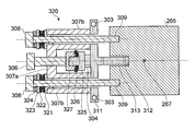
- the vibration unit 320 has the same configuration as that of the vibration unit 310 shown in FIG. 7, and includes first and second elastic members 322 and 326, first and second bases. 321 and 327, washers 323, and shims 324 may further be provided. Further, the pressing member 305 in the vibration unit 310 may be replaced with the pressing member 325.
- the first elastic member 322 may be disposed between the head of the first bolt 308 and the pressurizing frame 307.
- a first pedestal 321 may be disposed between the elastic member 322 and the pressurizing frame 307.
- a washer 323 and one or more shims 324 may be disposed between the elastic member 322 and the head of the first bolt 308.
- the second pedestal 327 may be disposed at the tip of the shaft portion of the second bolt 306.
- the second pedestal 327 and the pressing member 325 may have a convex part and a concave part that fit together.
- the second elastic member 326 may be disposed between the second pedestal 327 and the pressing member 325.
- the first elastic member 322 may be a ring-shaped member that can be inserted into the shaft portion of the first bolt 308.
- the second elastic member 326 may be a ring-shaped member that can be inserted into the convex portion of the second pedestal 327 or the pressing member 325.
- These first and second elastic members 322 and 326 may be disc springs, for example.
- the 1st base 321 and the 2nd base 327 may hold
- the fluctuation of the pressure applied to the piezo element 304 can be mitigated by the elastic force and stroke of the first and second elastic members 322 and 326.
- each elastic force and stroke may be adjusted by adjusting the number of sheets, the overlapping direction, hardness, etc.
- the load (preload) given in advance to the first elastic member 322 and the second elastic member 326 may be adjusted by adjusting the screwing torque of the first bolt 308 and the second bolt 306. Further, when the shim 324 is interposed between the first bolt 308 and the first elastic member 322, the preload and the stroke of the first elastic member 322 are adjusted by adjusting the thickness and the number of the shims 324. It may be adjusted.
- the pressure applied to the vibration transmission member 311 (vibration pin 312) and the pressure applied to the piezo element 304 are, for example, the surface pressure between the vibration pin 312 and the nozzle holder 265 is determined by the piezoelectric element 304 and the vibration transmission member 311. It may be adjusted so as to be larger than the surface pressure between. At that time, the surface pressure between the piezo element 304 and the vibration transmitting member 311 may be adjusted to about 30 MPa, for example.
- the vibration unit 320 according to the second embodiment is applied to the vibration transmission member 311 (vibration pin 312) when heated for the output of the target 27. Fluctuations in pressure and pressure applied to the piezo element 304 can be suppressed.
- the pressure applied to the vibration transmitting member 311 (excitation pin 312) and the pressure applied to the piezo element 304 can be reduced.
- the degree of freedom of adjustment can be greatly improved. Thereby, it is possible to accurately adjust the pressure applied to the vibration transmitting member 311 (excitation pin 312) and the pressure applied to the piezoelectric element 304. For this reason, the mechanical difference that the transmission efficiency of the vibration generated in the piezo element 304 is different for each excitation unit 300 can be reduced.
- bolt 306) of the vibration unit 320 may be comprised with a material with a comparatively small thermal expansion coefficient.
- the material of a material having a relatively small thermal expansion coefficient may be, for example, invar, an alloy mainly composed of nickel, or the like.
- first bolt 308 and the second bolt 306 may be made of a material having a relatively low thermal conductivity.
- the material having a relatively low thermal conductivity may be a ceramic such as aluminum nitride, silicon carbide, or boron nitride.
- the configuration in which the vibration unit 310 or 320 is attached to the nozzle holder 265 or the tank unit 260 is exemplified.
- the attachment position of the vibration unit is not limited to the nozzle holder 265 or the tank portion 260.
- other attachment positions of the vibration unit are illustrated.
- a configuration based on the vibration unit 320 illustrated in FIG. 8 is illustrated, but other embodiments illustrated in the present disclosure can be used as a base as well.
- FIG. 9 is a cross-sectional view illustrating an attachment example of the vibration unit according to the third embodiment.
- FIG. 9 shows a structural example of a cross section corresponding to FIG.
- the mounting position of the vibration unit is different from that in FIG. 10 is a cross-sectional view of the mounting example shown in FIG. 9 shows an example of the cross-sectional structure of the DD plane shown in FIG. 10, and
- FIG. 10 shows an example of the cross-sectional structure of the CC plane shown in FIG.
- the same components as those shown in FIG. 8 are denoted by the same reference numerals, and redundant description is omitted.
- a vibration transmission member (first or third member) 331 may be disposed between the tank portion 260 and the nozzle holder 265. Therefore, a convex portion or a concave portion that fits with the concave portion or the convex portion of the vibration transmitting member 331 may be provided at the bottom of the tank portion 260. Further, the nozzle holder 265 may be provided with a recess or projection that fits with the projection or recess of the vibration transmitting member 331. A surface seal may be sealed between the tank portion 260 and the vibration transmission member 331 and between the vibration transmission member 331 and the nozzle holder 265.
- the vibration transmission member 331 may be provided with a flow path that communicates with the target flow path FL of the tank portion 260 and extends the target flow path FL to the nozzle member 266 of the nozzle holder 265.
- the channel is referred to as a target channel FL without being distinguished from the target channel FL.
- the contact area between the vibration transmission member 331 and the target material 271, that is, the inner surface area of the target flow path FL in the vibration transmission member 331 may be smaller than the contact area with the target material 271 in the tank portion 260. Therefore, the vibration transmission member 331 may be a member having a smaller volume than the tank portion 260.
- the material of the vibration transmission member 331 may be a material having low reactivity with the target material 271.
- the material of the vibration transmitting member 331 may be a material having a thermal expansion coefficient close to that of the tank portion 260 or the like. Therefore, for example, when the material of the tank portion 260 is molybdenum, molybdenum may be used as the material of the vibration transmission member 331.
- the material of the vibration transmission member 331 may be a material having a vibration attenuation factor lower than that of the tank part 260 or the nozzle holder 265.
- Examples of materials that can be selected as the material of the vibration transmitting member 331 are shown in the table of FIG. Among the materials listed in FIG. 11, molybdenum, silicon carbide, tungsten carbide, aluminum nitride, zirconium boride, and boron carbide have a possibility of being particularly effective as a material for the vibration transmission member 331.
- the side surface of the vibration transmission member 331 may be provided with two screw holes into which the tips 309 of the two first bolts 308 in the vibration unit 320 are screwed.
- the vibration unit 320 may be fixed to the vibration transmission member 331 by screwing the tips 309 of the two first bolts 308 into these two screw holes.
- a vibration hole 313 corresponding to the vibration pin 312 may be provided on the side surface of the vibration transmission member 331.
- the vibration generated in the piezo element 304 passes from the vibration pin 312 of the vibration transmission member 311 to the target material 271 in the target flow path FL via the vibration transmission member 331. May be communicated. Thereby, the jet of the target material 271 ejected from the nozzle hole 267 may be divided and changed into droplets having a predetermined size and a predetermined cycle.
- the vibration generated in the vibration unit 320 can be directly transmitted to the vibration transmission member 331 that directly contacts the target material 271 in the target flow path FL. Thereby, vibration can be more efficiently transmitted to the target material 271 in the target flow path FL.
- vibration transmitting member 331 is made of a material having a low vibration attenuation rate, vibration can be more efficiently transmitted to the target material 271 in the target flow path FL.
- the vibration transmission member 331 can be suppressed from consuming vibration energy due to vibration of the entire member by being a member smaller than the tank portion 260.
- the contact area with the target material 271 can be reduced, the density of vibration energy transmitted to the contact surface with the target material 271 can be increased. Thereby, vibration can be more efficiently transmitted to the target material 271 in the target flow path FL.
- the tip portion of the vibration pin 312 may have a tapered shape that has a smaller cross-sectional area than the cross-sectional area on the base side.
- the cross-sectional area at this time may be a cross-sectional area in a plane perpendicular to the extending direction of the excitation pin 312.
- the excitation pin 312 is a substantially cylinder, the cross-sectional area of a cylinder may be sufficient.
- FIG. 12 is a cross-sectional view illustrating a schematic shape of a vibration pin according to a first modification.
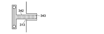
- the tip end portion 343 of the excitation pin 342 may have a tapered shape, so that the cross-sectional area thereof may be reduced.
- FIG. 13 is a cross-sectional view showing a schematic shape of an excitation pin according to a second modification.
- the tapered shape of the taper is not limited to the tip portion, and may be a shape with respect to the entire excitation pin 352.
- FIG. 14 is a cross-sectional view illustrating a schematic shape of an excitation pin according to a third modification.
- the excitation pin 362 may include a tip portion 363 that is narrower than the trunk portion on the root side.
- a narrower substantially cylindrical tip 363 may be provided through a stepped step.
- FIG. 15 is a cross-sectional view illustrating a schematic shape of a vibration pin according to a fourth modified example.
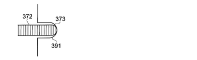
- the tip 373 of the excitation pin 372 may have a convex curved shape.
- the convex curved surface may be various curved surfaces such as a spherical surface, a spheroid surface, and a hyperboloid surface.
- the contact between the vibration hole 313 and the tip 373 may be a point contact substantially.
- the tip surface of the excitation pin 312 and the bottom surface of the excitation hole 313 may be flat. In that case, the tip of the vibration pin 312 and the bottom surface of the vibration hole 313 can substantially form surface contact. However, it is not limited to this. For example, as illustrated in the fourth modification shown in FIG. 15, the tip of the vibration pin and the bottom surface of the vibration hole may form a point contact or a line contact.
- FIG. 16 is a cross-sectional view illustrating an example of a contact form between a vibration pin and a vibration hole according to a first modification.
- the shape of the bottom surface of the excitation hole 391 that receives it may be a concave curved surface shape.
- the convex curved surface and the concave curved surface may be various curved surfaces such as a spherical surface, a spheroid surface, and a hyperboloid surface.
- the concave curved surface on the bottom surface of the excitation hole 391 may be a shape closer to a plane than the convex curved surface of the tip portion 373.
- the radius of curvature of the convex spherical surface of the tip portion 373 is larger than the curvature radius of the concave spherical surface of the bottom surface of the excitation hole 391. It may be small.
- FIG. 17 is a cross-sectional view illustrating an example of a contact form between a vibration pin and a vibration hole according to a second modification.
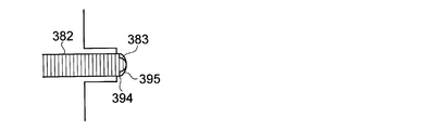
- the portion having the convex curved surface in the tip portion 383 of the excitation pin 382 may be a part of the tip surface.
- the portion having the concave curved surface on the inner surface of the excitation hole 392 may be a part of the bottom surface.
- the concave curved surface on the bottom surface of the excitation hole 392 may be a shape closer to a plane than the convex curved surface of the tip portion 383.
- the contact form between the excitation pin and the excitation hole is substantially the same. Since point contact is achieved, the contact area between the vibration transmission member 311 serving as a vibration transmission unit and the nozzle holder 265 or the tank unit 260 (or the vibration transmission member 331) can be significantly reduced. As a result, vibration can be transmitted more efficiently.
- FIG. 18 is a cross-sectional view illustrating an example of a contact form between a vibration pin and a vibration hole according to a third modification.
- the bottom surface of the excitation hole 393 has multipoint contact or line contact with the peripheral portion of the tip portion 373 in addition to the surface that makes point contact with the most distal portion of the tip portion 373 of the excitation pin 372.
- the positioning part 394 to be formed may be included.
- the vibration pin 372 may have the same shape as the vibration pin 372 illustrated in FIG.
- the positioning part 394 may be a stepped step extending around the bottom surface of the excitation hole 393.
- the positioning portion 394 may hold the vibration pin 372 at a correct position with respect to the vibration hole 393 by contacting the peripheral portion of the tip portion 373.
- FIG. 19 is a cross-sectional view showing an example of a contact form between a vibration pin and a vibration hole according to a fourth modification.
- the surface that makes point contact with the foremost portion of the tip 373 of the excitation pin 372 may be a concave curved surface.
- the vibration pin 382 may have the same shape as the vibration pin 382 illustrated in FIG.
- the positioning part 394 in the fourth modification may form multipoint contact, line contact, or surface contact with the periphery of the body portion of the vibration pin 382.
- the shape of the positioning portion 394 is not limited to the above-described step.
- the shape of the positioning portion 394 may be designed based on a predetermined fit tolerance with respect to the outer shape of the opposing excitation pin.
- excitation holes 321 ... first base, 322 ... first elastic member, 323 ... washer, 324 ... Shim, 326 ... Second elastic member, 327 ... Second base, 331 ... Vibration transmitting member, 394 ... Positioning portion
Landscapes
- Physics & Mathematics (AREA)
- Optics & Photonics (AREA)
- Engineering & Computer Science (AREA)
- Plasma & Fusion (AREA)
- X-Ray Techniques (AREA)
- Exposure And Positioning Against Photoresist Photosensitive Materials (AREA)
Abstract
本開示の一態様による加振ユニットは、ターゲット流路(FL)内に供給されたターゲット材料(271)に振動を与える加振ユニット(310,320)であって、前記ターゲット流路を内部に含む第1部材(265,260,331)に接触する振動伝達部材(311,321)と、前記振動伝達部材に接触し、外部からの電気信号に応じて振動する圧電部材(304)と、を備えてもよい。前記振動伝達部材の振動減衰率は、前記第1部材の振動減衰率よりも小さくてもよい。
Description
本開示は、極端紫外(EUV)光を生成するためにレーザ光に照射される加振ユニット、ターゲット供給装置および極端紫外光生成装置に関する。
近年、半導体プロセスの微細化に伴って、半導体プロセスの光リソグラフィにおける転写パターンの微細化が急速に進展している。次世代においては、70nm~45nmの微細加工、さらには32nm以下の微細加工が要求されるようになる。このため、例えば32nm以下の微細加工の要求に応えるべく、波長13nm程度の極端紫外(EUV)光を生成するための装置と縮小投影反射光学系(reduced projection reflective optics)とを組み合わせた露光装置の開発が期待されている。
EUV光生成装置としては、ターゲット物質にレーザ光を照射することによって生成されるプラズマを用いたLPP(Laser Produced Plasma)方式の装置と、放電によって生成されるプラズマを用いたDPP(Discharge Produced Plasma)方式の装置と、軌道放射光を用いたSR(Synchrotron Radiation)方式の装置との3種類の装置が提案されている。
本開示の一態様による加振ユニットは、ターゲット流路(FL)内に供給されたターゲット材料(271)に振動を与える加振ユニット(310,320)であって、前記ターゲット流路を内部に含む第1部材(265,260,331)に接触する振動伝達部材(311,321)と、前記振動伝達部材に接触し、外部からの電気信号に応じて振動する圧電部材(304)と、を備え、前記振動伝達部材の振動減衰率は、前記第1部材の振動減衰率よりも小さくてもよい。
また、本開示の他の態様によるターゲット供給装置は、ターゲット流路を内部に含む第1部材と、前記第1部材に接触する振動伝達部材と、前記振動伝達部材に接触し、外部からの電気信号に応じて振動する圧電部材とを備える加振ユニットと、を備え、前記振動伝達部材の振動減衰率は、前記第1部材の振動減衰率よりも小さくてもよい。
また、本開示のさらに他の態様によるターゲット供給装置は、ターゲット流路を内部に含む第1部材と、前記第1部材に接触する振動伝達部材と、前記振動伝達部材に接触し、外部からの電気信号に応じて振動する圧電部材とを備える加振ユニットと、を備え、前記第1部材と前記振動伝達部材との接触位置には、当該接触位置を前記ターゲット流路に近づける凹形状(313,343,363,373,391,392,393,395)が設けられていてもよい。
また、本開示のさらに他の態様によるターゲット供給装置は、ターゲット流路を内部に含む第1部材(265,331)と、前記ターゲット流路へ供給されるターゲット材料を貯留する第2部材(260)と、前記第1部材に接触する振動伝達部材と、前記振動伝達部材に接触し、外部からの電気信号に応じて振動する圧電部材とを備える加振ユニットと、を備え、前記第1部材と前記ターゲット材料との接触面積は、前記第2部材と前記ターゲット材料との接触面積よりも小さくてもよい。
また、本開示のさらに他の態様による極端紫外光生成装置は、チャンバと、前記チャンバ内へ前記ターゲット物質を供給する上記いずれかのターゲット供給装置と、前記チャンバ内へ供給された前記ターゲット物質へレーザ光を照射するレーザ装置と、前記レーザ光が照射されることで生成された前記ターゲット物質のプラズマから放射した極端紫外光を集光して出力するコレクタミラーと、を備えてもよい。
本開示のいくつかの実施形態を、単なる例として、添付の図面を参照して以下に説明する。
図1は、例示的なLPP方式のEUV光生成システムの構成を概略的に示す図である。
図2は、図1に示すターゲット供給部を含むターゲット供給装置の一例を示す模式図である。
図3は、図2に示すノズル部材、ノズルホルダおよび加振ユニットを下方から見たときの概略構成を示す図である。
図4は、図2に示す加振ユニットの一例を示す斜視図である。
図5は、図4に示す加振ユニットの水平断面図である。
図6は、図4に示す加振ユニットの垂直断面図である。
図7は、実施形態1にかかる加振ユニットの概略構成例を示す水平断面図である。
図8は、実施形態2にかかる加振ユニットの概略構成例を示す水平断面図である。
図9は、実施形態3にかかる加振ユニットの取り付け例を示す水平断面図である。
図10は、図9に示す取り付け例の垂直断面図である。
図11は、実施形態3において振動伝達部材の材料として選択し得る材料の例を示す図である。
図12は、加振ピンの第1変形例にかかる加振ピンの概略形状を示す断面図である。
図13は、加振ピンの第2変形例にかかる加振ピンの概略形状を示す断面図である。
図14は、加振ピンの第3変形例にかかる加振ピンの概略形状を示す断面図である。
図15は、加振ピンの第4変形例にかかる加振ピンの概略形状を示す断面図である。
図16は、加振ピンと加振穴との接触形態の第1変形例にかかる概略形状を示す断面図である。
図17は、加振ピンと加振穴との接触形態の第2変形例にかかる概略形状を示す断面図である。
図18は、加振ピンと加振穴との接触形態の第3変形例にかかる概略形状を示す断面図である。
図18は、加振ピンと加振穴との接触形態の第4変形例にかかる概略形状を示す断面図である。
内容
1.概要
2.極端紫外光生成装置の全体説明
2.1 構成
2.2 動作
3.用語の説明
4.加振ユニットを含むターゲット供給装置
4.1 構成
4.2 動作
5.加振ユニット:比較例
5.1 構成
5.2 動作
5.3 課題
6.加振ユニット:実施形態1
6.1 構成
6.2 動作
6.3 作用
7.加振ユニット:実施形態2
7.1 構成
7.2 動作
7.3 作用
8.加振ユニット:実施形態3
8.1 構成
8.2 動作
8.3 作用
9.加振ピンの変形例
9.1 第1変形例
9.2 第2変形例
9.3 第3変形例
9.4 第4変形例
9.5 変形例による作用
10.加振ピンと加振穴との接触形態の変形例
10.1 第1変形例
10.2 第2変形例
10.3 第1および第2変形例による作用
10.4 第3変形例
10.5 第4変形例
10.3 第3および第4変形例による作用
1.概要
2.極端紫外光生成装置の全体説明
2.1 構成
2.2 動作
3.用語の説明
4.加振ユニットを含むターゲット供給装置
4.1 構成
4.2 動作
5.加振ユニット:比較例
5.1 構成
5.2 動作
5.3 課題
6.加振ユニット:実施形態1
6.1 構成
6.2 動作
6.3 作用
7.加振ユニット:実施形態2
7.1 構成
7.2 動作
7.3 作用
8.加振ユニット:実施形態3
8.1 構成
8.2 動作
8.3 作用
9.加振ピンの変形例
9.1 第1変形例
9.2 第2変形例
9.3 第3変形例
9.4 第4変形例
9.5 変形例による作用
10.加振ピンと加振穴との接触形態の変形例
10.1 第1変形例
10.2 第2変形例
10.3 第1および第2変形例による作用
10.4 第3変形例
10.5 第4変形例
10.3 第3および第4変形例による作用
以下、本開示の実施形態について、図面を参照しながら詳しく説明する。以下に説明される実施形態は、本開示のいくつかの例を示すものであって、本開示の内容を限定するものではない。また、各実施形態で説明される構成及び動作の全てが本開示の構成及び動作として必須であるとは限らない。なお、同一の構成要素には同一の参照符号を付して、重複する説明を省略する。
1.概要
本開示の実施形態は、EUV光生成用のターゲット材料をドロップレットの形態で供給するためのターゲット供給装置に用いられる加振ユニット、およびそれを備えたターゲット供給装置およびEUV光生成装置に関するものであってよい。より具体的には、実施形態は、ノズルからジェット状に噴出したターゲット材料をドロップレットの形態に変化させるための振動をノズル先端に与える加振ユニット、およびそれを備えたターゲット供給装置およびEUV光生成装置に関するものであってもよい。ただし、本開示はこれらの事項に限定されず、ジェット状に噴出した液体をドロップレットの形態に変化させるためのあらゆる事項に関連するものであってよい。
本開示の実施形態は、EUV光生成用のターゲット材料をドロップレットの形態で供給するためのターゲット供給装置に用いられる加振ユニット、およびそれを備えたターゲット供給装置およびEUV光生成装置に関するものであってよい。より具体的には、実施形態は、ノズルからジェット状に噴出したターゲット材料をドロップレットの形態に変化させるための振動をノズル先端に与える加振ユニット、およびそれを備えたターゲット供給装置およびEUV光生成装置に関するものであってもよい。ただし、本開示はこれらの事項に限定されず、ジェット状に噴出した液体をドロップレットの形態に変化させるためのあらゆる事項に関連するものであってよい。
2.EUV光生成システムの全体説明
2.1 構成
図1に、例示的なLPP方式のEUV光生成システムの構成を概略的に示す。EUV光生成装置1は、少なくとも1つのレーザ装置3と共に用いられてもよい。本願においては、EUV光生成装置1及びレーザ装置3を含むシステムを、EUV光生成システム11と称する。図1に示し、かつ、以下に詳細に説明するように、EUV光生成装置1は、チャンバ2、ターゲット供給部26を含んでもよい。チャンバ2は、密閉可能であってもよい。ターゲット供給部26は、例えば、チャンバ2の壁を貫通するように取り付けられてもよい。ターゲット供給部26から供給されるターゲット物質の材料は、スズ、テルビウム、ガドリニウム、リチウム、キセノン、又は、それらの内のいずれか2つ以上の組合せを含んでもよいが、これらに限定されない。
2.1 構成
図1に、例示的なLPP方式のEUV光生成システムの構成を概略的に示す。EUV光生成装置1は、少なくとも1つのレーザ装置3と共に用いられてもよい。本願においては、EUV光生成装置1及びレーザ装置3を含むシステムを、EUV光生成システム11と称する。図1に示し、かつ、以下に詳細に説明するように、EUV光生成装置1は、チャンバ2、ターゲット供給部26を含んでもよい。チャンバ2は、密閉可能であってもよい。ターゲット供給部26は、例えば、チャンバ2の壁を貫通するように取り付けられてもよい。ターゲット供給部26から供給されるターゲット物質の材料は、スズ、テルビウム、ガドリニウム、リチウム、キセノン、又は、それらの内のいずれか2つ以上の組合せを含んでもよいが、これらに限定されない。
チャンバ2の壁には、少なくとも1つの貫通孔が設けられていてもよい。その貫通孔には、ウインドウ21が設けられてもよく、ウインドウ21をレーザ装置3から出力されるパルスレーザ光32が透過してもよい。チャンバ2の内部には、例えば、回転楕円面形状の反射面を有するEUV集光ミラー23が配置されてもよい。EUV集光ミラー23は、第1及び第2の焦点を有し得る。EUV集光ミラー23の表面には、例えば、モリブデンとシリコンとが交互に積層された多層反射膜が形成されていてもよい。EUV集光ミラー23は、例えば、その第1の焦点がプラズマ生成領域25に位置し、その第2の焦点が中間集光点(IF)292に位置するように配置されるのが好ましい。EUV集光ミラー23の中央部には貫通孔24が設けられていてもよく、貫通孔24をパルスレーザ光33が通過してもよい。
EUV光生成装置1は、EUV光生成制御装置5、ターゲットセンサ4等を含んでもよい。ターゲットセンサ4は、撮像機能を有してもよく、ターゲット27の存在、軌跡、位置、速度等を検出するよう構成されてもよい。
また、EUV光生成装置1は、チャンバ2の内部と露光装置6の内部とを連通させる接続部29を含んでもよい。接続部29内部には、アパーチャ293が形成された壁291が設けられてもよい。壁291は、そのアパーチャ293がEUV集光ミラー23の第2の焦点位置に位置するように配置されてもよい。
さらに、EUV光生成装置1は、レーザ光進行方向制御部34、レーザ光集光ミラー22、ターゲット27を回収するためのターゲット回収部28等を含んでもよい。レーザ光進行方向制御部34は、レーザ光の進行方向を規定するための光学素子と、この光学素子の位置、姿勢等を調整するためのアクチュエータとを備えてもよい。
2.2 動作
図1を参照に、レーザ装置3から出力されたパルスレーザ光31は、レーザ光進行方向制御部34を経て、パルスレーザ光32としてウインドウ21を透過してチャンバ2内に入射してもよい。パルスレーザ光32は、少なくとも1つのレーザ光経路に沿ってチャンバ2内に進み、レーザ光集光ミラー22で反射されて、パルスレーザ光33として少なくとも1つのターゲット27に照射されてもよい。
図1を参照に、レーザ装置3から出力されたパルスレーザ光31は、レーザ光進行方向制御部34を経て、パルスレーザ光32としてウインドウ21を透過してチャンバ2内に入射してもよい。パルスレーザ光32は、少なくとも1つのレーザ光経路に沿ってチャンバ2内に進み、レーザ光集光ミラー22で反射されて、パルスレーザ光33として少なくとも1つのターゲット27に照射されてもよい。
ターゲット供給部26は、ターゲット27をチャンバ2内部のプラズマ生成領域25に向けて出力するよう構成されてもよい。ターゲット27には、パルスレーザ光33に含まれる少なくとも1つのパルスが照射されてもよい。パルスレーザ光が照射されたターゲット27はプラズマ化し、そのプラズマから放射光251が放射され得る。放射光251に含まれるEUV光252は、EUV集光ミラー23によって選択的に反射されてもよい。EUV集光ミラー23によって反射されたEUV光252は、中間集光点292で集光され、露光装置6に出力されてもよい。なお、1つのターゲット27に、パルスレーザ光33に含まれる複数のパルスが照射されてもよい。
EUV光生成制御装置5は、EUV光生成システム11全体の制御を統括するよう構成されてもよい。EUV光生成制御装置5は、ターゲットセンサ4によって撮像されたターゲット27のイメージデータ等を処理するよう構成されてもよい。また、EUV光生成制御装置5は、例えば、ターゲット27が出力されるタイミング、ターゲット27の出力方向等を制御するよう構成されてもよい。さらに、EUV光生成制御装置5は、例えば、レーザ装置3の発振タイミング、パルスレーザ光32の進行方向、パルスレーザ光33の集光位置等を制御するよう構成されてもよい。上述の様々な制御は単なる例示に過ぎず、必要に応じて他の制御が追加されてもよい。
3.用語の説明
本開示において使用される用語について、以下のように定義する。
「ドロップレット」とは、溶融したターゲット材料の液滴であってもよい。その形状は、略球形であってもよい。
「プラズマ生成領域」とは、プラズマが生成される空間として予め設定された3次元空間であってもよい。
本開示において使用される用語について、以下のように定義する。
「ドロップレット」とは、溶融したターゲット材料の液滴であってもよい。その形状は、略球形であってもよい。
「プラズマ生成領域」とは、プラズマが生成される空間として予め設定された3次元空間であってもよい。
4.加振ユニットを含むターゲット供給装置
つづいて、図1に示すターゲット供給部26を含むターゲット供給装置の一例を、図面を参照して詳細に説明する。
つづいて、図1に示すターゲット供給部26を含むターゲット供給装置の一例を、図面を参照して詳細に説明する。
4.1 構成
図2は、図1に示すターゲット供給部を含むターゲット供給装置の一例を示す模式図である。図3は、図2に示すノズル部材、ノズルホルダおよび加振ユニットをターゲットの出力方向から見たときの概略構成を示す図である。
図2は、図1に示すターゲット供給部を含むターゲット供給装置の一例を示す模式図である。図3は、図2に示すノズル部材、ノズルホルダおよび加振ユニットをターゲットの出力方向から見たときの概略構成を示す図である。
図2に示すように、ターゲット供給装置は、タンク部(第1または第2部材)260と、ノズル部材266と、圧力調節器120と、温度コントローラ144と、ターゲット制御装置51と、加振ユニット111と、ピエゾ電源112とを含んでいてもよい。
タンク部260内には、ターゲット材料271である錫(Sn)が貯蔵されてもよい。タンク部260の材質は、錫との反応性が低い材質であってもよい。錫との反応性が低い材質の材料は、たとえばモリブデン(Mo)であってもよい。
ノズル部材266には、3~6μmの孔径のノズル孔267が形成されていてもよい。ノズル部材266の材質は、錫との反応性が低い材質(たとえばMo)であってもよい。ノズル部材266は、ノズルホルダ(第1部材)265によってタンク部260の底部に固定されてもよい。ノズルホルダ265の材質は、錫との反応性が低い材質(たとえばMo)であってもよい。ノズル部材266とノズルホルダ265との間、および、タンク部260とノズル部材266との間は、それぞれ面シールされていてもよい。
圧力調節器120には、不活性ガスのボンベ130が接続されてもよい。ボンベ130と圧力調整器120との間のガス配管上には、圧力調整器120によって制御可能なバルブ134が設けられてもよい。圧力調節器120は、導入管131を介してタンク部260内に連通していてもよい。圧力調節器120は、ボンベ130から供給された不活性ガスを、導入管131を介してタンク部260内に導入してもよい。
温度コントローラ144は、温度センサ142とヒータ電源143とに接続されてもよい。温度センサ142は、タンク部260またはノズルホルダ265の温度を計測するように配置されていてもよい。ヒータ電源143は、ヒータ141に電気的に接続されていてもよい。ヒータ電源143は、温度コントローラ144からの制御に従って、ヒータ141に電流を供給してもよい。ヒータ141は、タンク部260内のターゲット材料271を加熱するように配置されていてもよい。たとえば、ヒータ141は、タンク部260の外側面に配置されていてもよい。
温度センサ142と温度コントローラ144とは、チャンバ2の隔壁に設けられた導入端子142aを介して電気的に接続されていてもよい。導入端子142aは、チャンバ2の気密性を維持しつつ、温度センサ142と温度コントローラ144との接続ラインをチャンバ2から電気的に絶縁してもよい。
ピエゾ電源112は、ターゲット制御装置51と、加振ユニット111とに接続されていてもよい。ピエゾ電源112と加振ユニット111とは、同じくチャンバ2の隔壁に設けられた導入端子111aを介して電気的に接続されていてもよい。導入端子111aは、チャンバ2の気密性を維持しつつ、ピエゾ電源112と加振ユニット111との接続ラインをチャンバ2から電気的に絶縁してもよい。
図2および図3に示すように、加振ユニット111は、ノズルホルダ265の側面に設けられてもよい。加振ユニット111が複数配置される場合、加振ユニット111は、ノズル孔267の中心を通る軸に対して線対称の関係となるように配置されてもよい。各加振ユニット111の詳細については、後述する。
また、図2に示すように、ターゲット制御装置51は、加振ユニット111と、温度コントローラ144と、圧力調節器120と、EUV光生成制御装置5とに接続されていてもよい。
タンク部260の内部は、タンク部260の底部に設けられたターゲット流路を介してノズル孔267に連通していてもよい。ターゲット流路には、流通するターゲット材料271を濾過するための不図示のフィルタが配置されてもよい。
4.2 動作
図2に示すターゲット制御装置51は、EUV光生成制御装置5または外部装置の制御部からドロップレット出力準備信号が入ると以下の処理を実行してもよい。
図2に示すターゲット制御装置51は、EUV光生成制御装置5または外部装置の制御部からドロップレット出力準備信号が入ると以下の処理を実行してもよい。
すなわち、ターゲット制御装置51は、まず、タンク部260内のターゲット材料271が融点以上の温度となるように、温度コントローラ144を制御してもよい。これに対し、温度コントローラ144は、温度センサ142の検出値が所定の温度以上となるよう、ヒータ電源143を駆動してもよい。所定の温度は、たとえばターゲット材料271として錫(Sn)を使用した場合、錫の融点(温度232℃)以上の温度であってもよい。また、所定の温度は、温度範囲であってもよい。温度範囲は、たとえば240℃~290℃であってもよい。
つづいて、ターゲット制御装置51は、温度センサ142の検出値が所定時間、所定の温度以上を維持しているか否かを判定してもよい。所定の温度以上が所定時間維持されている場合、ターゲット制御装置51は、EUV光生成制御装置5または外部装置の制御部にドロップレットの出力準備が完了したことを通知してもよい。その後、ターゲット制御装置51は、ドロップレット27の出力を要求するドロップレット出力信号が入力されるまで待機してもよい。
つぎに、ターゲット制御装置51は、ドロップレット出力信号が入力されると、圧力調整器120を制御して、タンク部260内の圧力を所定圧力まで昇圧してもよい。所定圧力は、たとえば10MPa(メガパスカル)程度であってもよい。また、ターゲット制御装置51は、圧力調整器120を制御して、タンク部260内の圧力を所定圧力に維持してもよい。タンク部260内の圧力が所定圧力に維持された状態では、ノズル孔267からターゲット材料271のジェットが出力されてもよい。
つづいて、ターゲット制御装置51は、ノズル孔267から吐出するターゲット材料271のジェットが所定サイズおよび所定周期のドロップレットに変化するように、ピエゾ電源112を制御してもよい。これにより、ピエゾ電源112から加振ユニット111に、所定波形の電圧が印加されてもよい。所定波形の電圧が印加された加振ユニット111で発生した振動は、ノズルホルダ265、ノズル部材266およびタンク部260を介してターゲット材料271に伝達してもよい。その結果、ターゲット材料271のジェットが分断され、所定サイズおよび所定周期のドロップレットに変化してもよい。
5.加振ユニット:比較例
つづいて、図2および図3に示す加振ユニット111の一例について、図面を参照して詳細に説明する。
つづいて、図2および図3に示す加振ユニット111の一例について、図面を参照して詳細に説明する。
5.1 構成
図4は、図2に示す加振ユニットの一例を示す斜視図である。図5は、図4に示す加振ユニットの2本の第1ボルト308の中心軸を含む面における断面図であり、図6は、図5の断面と垂直かつ、第2ボルト306の中心軸を含む面における断面図である。なお、図5は、図6に示すB-B面の断面構造の一例を示し、図6は、図5に示すA-A面の断面構造の一例を示す。
図4は、図2に示す加振ユニットの一例を示す斜視図である。図5は、図4に示す加振ユニットの2本の第1ボルト308の中心軸を含む面における断面図であり、図6は、図5の断面と垂直かつ、第2ボルト306の中心軸を含む面における断面図である。なお、図5は、図6に示すB-B面の断面構造の一例を示し、図6は、図5に示すA-A面の断面構造の一例を示す。
図4~図6に例示する加振ユニット300は、2本の第1ボルト308と、第2ボルト306と、与圧用フレーム307と、押さえ部材305と、ピエゾ素子304と、振動伝達部材301とを含んでもよい。
与圧用フレーム307は、加振ユニット300のフレーム部材であってもよい。この与圧用フレーム307は、両側に位置する一方のアーム部307bと、他方のアーム部307bを連結する中央の梁部307aとを含んでもよい。
振動伝達部材301は、与圧用フレーム307とノズルホルダ265との間に配置されてもよい。振動伝達部材301の中央部には、先端側が細い円錐台状の突起部302が設けられてもよい。突起部302の先端は、ノズルホルダ265の側面に接触してもよい。突起部302の先端とノズルホルダ265の側面との接触面積は、ピエゾ素子304の何れか1つの面の面積よりも小さくてもよい。
2本の第1ボルト308は、与圧用フレーム307と振動伝達部材301とを、ノズルホルダ265の側面に固定してもよい。そこで、第1ボルト308の軸部の先端309には、ねじ部が形成されていてもよい。ノズルホルダ265の側面には、2つの第1ボルト308の軸部の先端309が螺合される2つのねじ穴が設けられていてもよい。与圧用フレーム307における2つのアーム部307bおよび振動伝達部材301には、2本の第1ボルト308をそれぞれ嵌挿するための2つの貫通孔が設けられていてもよい。
第2ボルト306は、ピエゾ素子304および振動伝達部材301をノズルホルダ265に押し付ける圧力を調整する調整部材であってもよい。そこで、与圧用フレーム307における中央の梁部307aには、第2ボルト306を螺合するためのねじ穴が設けられていてもよい。
振動伝達部材301は、与圧用フレーム307に螺合された第2ボルト306によってノズルホルダ302側へ付勢されてもよい。第2ボルト306振動伝達部材301との間には、ピエゾ素子304および押さえ部材305が配置されてもよい。第2ボルト306は、押さえ部材305を介してピエゾ素子304を振動伝達部材301へ押し付けつつ、振動伝達部材301の突起部302をノズルホルダ265へ押し付けてもよい。
ピエゾ素子304は、外部からの電気信号に応じて振動する圧電部材であってもよい。このピエゾ素子304は、図示しない配線によってピエゾ電源112(図2参照)に接続されてもよい。ピエゾ素子304は、チタン酸ジルコン酸鉛を用いた圧電素子であってよい。また、振動伝達部材301には、冷却水配管303が設けられてもよい。冷却水配管303は、図示しない冷却水温度調節装置に接続されてもよい。
なお、加振ユニット300の取り付け位置は、ノズルホルダ265の側面に限られない。たとえば、加振ユニット300がタンク部260の側面に取り付けられてもよい。すなわち、加振ユニット300は、タンク部260内からノズル孔267までのターゲット流路FL内に存在するターゲット材料271に振動を与えられる位置であれば、いかなる場所に取り付けられてもよい。
5.2 動作
図4~図6に示す加振ユニット300では、振動伝達部材301の突起部302をノズルホルダ265へ押し付ける与圧、および、ピエゾ素子304を押さえ部材305と振動伝達部材301とで挟み込む与圧(ピエゾ素子304への与圧)が、第2ボルト306によって与えられてもよい。
図4~図6に示す加振ユニット300では、振動伝達部材301の突起部302をノズルホルダ265へ押し付ける与圧、および、ピエゾ素子304を押さえ部材305と振動伝達部材301とで挟み込む与圧(ピエゾ素子304への与圧)が、第2ボルト306によって与えられてもよい。
具体的には、与圧用フレーム307におけるアーム部307bの貫通孔および振動伝達部材301の貫通孔に嵌挿された状態の第1ボルト308をノズルホルダ265のねじ穴にねじ込むことで、振動伝達部材301をノズルホルダ265へ押し付ける与圧が振動伝達部材301の両側端に与えられてもよい。
また、第2ボルト306を与圧用フレーム307の梁部307aにねじ込むことで、突起部302をノズルホルダ265へ押し付ける与圧が押さえ部材305およびピエゾ素子304を介して振動伝達部材301の中央付近に与えられてもよい。また、同様にして、ピエゾ素子304を押さえ部材305と振動伝達部材301とで挟み込む与圧が与えられてもよい。なお、第2ボルト306によって与えられる与圧は、振動伝達部材301の突起部302をノズルホルダ265に押し付ける与圧であってもよい。
上記した与圧は、第1ボルト308および第2ボルト306のねじ込みトルクを調整することによって、調節され得る。その際、ピエゾ素子304で発生した振動が振動伝達部材301の突起部302を介してタンク部260内のターゲット材料271に到達するように、第1ボルト308および第2ボルト306のねじ込みトルクが調整されてもよい。
ピエゾ素子304は、ピエゾ電源112から印加された所定波形の電圧に基づいて伸縮することで、振動を発生してもよい。発生した振動は、振動伝達部材301の突起部302、ノズルホルダ265、ノズル部材266、タンク部260等を介して、ターゲット流路FL内のターゲット材料271に伝達してもよい。それにより、ノズル孔267から吐出するターゲット材料271のジェットが所定サイズおよび所定周期のドロップレットに変化し得る。
振動伝達部材301は、冷却水配管303を流れる冷却水で冷却されてもよい。それにより、タンク部260、ノズルホルダ265等を介して伝達するヒータ141からの熱によってピエゾ素子304の温度がキュリー点以上になることが抑制されてもよい。なお、ピエゾ素子304のキュリー点は、150℃から350℃の範囲であってもよい。
5.3 課題
ここで、EUV光生成装置1のチャンバ2内において発生するターゲット材料271のデブリを低減するためには、ドロップレット状に出力されるターゲット27の体積を小さくするとよい。微小なドロップレットを出力するためには、ノズル孔267の孔径(以下、ノズル径という)を小さくするとよい。
ここで、EUV光生成装置1のチャンバ2内において発生するターゲット材料271のデブリを低減するためには、ドロップレット状に出力されるターゲット27の体積を小さくするとよい。微小なドロップレットを出力するためには、ノズル孔267の孔径(以下、ノズル径という)を小さくするとよい。
ただし、たとえば加振ユニット300を含むターゲット供給装置においてノズル径を小さくすると、ドロップレットの生成周期が不安定になる可能性が存在する。これは、ノズル径を小さくした場合、ドロップレットを安定して生成するためにターゲット材料271に伝達されるべき振動周波数が上昇するためと考えらえる。
たとえば、ノズル径がΦ10μmの場合に安定したドロップレット生成に必要な振動周波数が1.5MHz(メガヘルツ)であるとすると、ノズル径がΦ6μmの場合に必要な振動周波数は3MHzとなり得る。
周波数1.5MHzの振動は、ターゲット材料271まで比較的良好に伝達され得る。しかしながら、ノズル径を小さくした場合に必要となる高周波の振動は、十分な振幅でターゲット材料271に伝達できない場合が存在し得る。その場合、ターゲット材料271のジェットを分断する力が弱くなるため、ドロップレットの生成が外乱の影響を受け易く、その結果、ドロップレットの生成周期が不安定になり得る。
そこで以下の実施形態では、比較的高周波の振動を十分な振幅で伝達し得る加振ユニットを例示する。
6.加振ユニット:実施形態1
まず、実施形態1にかかる加振ユニットについて、図面を参照して詳細に説明する。
まず、実施形態1にかかる加振ユニットについて、図面を参照して詳細に説明する。
上述したように、ノズルホルダ265やタンク部260など、ターゲット材料271と接触する部材は、ターゲット材料271との反応性が低いことが望ましい。そのため、それらの材質の選択に制限がかかり、必ずしも効率的に振動を伝達し得る最良の材料を選択できるとは限らない。そこで実施形態1では、発生した振動をターゲット材料271まで伝達する経路上に位置する部材であってターゲット材料271と接触しない部材に、比較的振動減衰率が低い材質が用いられてもよい。
ここで、比較的振動減衰率が低い材質とは、発生した振動をターゲット材料271まで伝達する経路上に位置する部材であってターゲット材料271に接触する部材の材質よりも振動減衰率が低い材質であってもよい。発生した振動をターゲット材料271まで伝達する経路上に位置する部材であってターゲット材料271に接触する部材とは、たとえばノズルホルダ265、ノズル部材266、タンク部260であってもよい。一方、発生した振動をターゲット材料271まで伝達する経路上に位置する部材であってターゲット材料271と接触しない部材とは、たとえば振動伝達部材であってもよい。
6.1 構成
図7は、実施形態1にかかる加振ユニットの概略構成例を示す断面図である。なお、図7は、図5に対応する断面の構造例を示している。また、以下の説明において、加振ユニット300と同様の構成については、同一の符号を付し、重複する説明を省略する。
図7は、実施形態1にかかる加振ユニットの概略構成例を示す断面図である。なお、図7は、図5に対応する断面の構造例を示している。また、以下の説明において、加振ユニット300と同様の構成については、同一の符号を付し、重複する説明を省略する。
図7に示すように、実施形態1にかかる加振ユニット310は、加振ユニット300と同様の構成において、振動伝達部材301が振動伝達部材311に置き換えられてもよい。
振動伝達部材311は、振動伝達部材301と同様の構成において、突起部302が加振ピン312に置き換えられてもよい。この加振ピン312は、振動伝達部材311の他の構成と一体であってもよいし、別々の部材であってもよい。
加振ピン312は、円柱形状であってもよい。加振ピン312の円形の断面積は、ピエゾ素子304の何れか1つの面の面積よりも小さくてもよい。
加振ピン312は、ノズルホルダ265やタンク部260等の材質よりも振動減衰率の低い材質で形成されてもよい。ノズルホルダ265やタンク部260等の材料としてモリブデンが用いられた場合、その対数振動減衰率は0.03であり得る。その場合、加振ピン312の材料には、たとえば対数振動減衰率が0.01(<0.03)であるステンレス等が用いられてもよい。また、振動伝達部材311の他の構成の材質もノズルホルダ265やタンク部260等の材質よりも振動減衰率の低い材質で形成されてもよい。
また、ノズルホルダ265における振動伝達部材311との接触部分には、加振穴313が設けられていてもよい。加振ピン312の先端は、加振穴313の底と接触してもよい。加振穴313は、ノズルホルダ265の側面からターゲット流路FLに向かう凹形状であってもよい。すなわち、加振穴313は、加振ピン312とノズルホルダ265との接触位置をターゲット流路FLに近づける形状であってもよい。接触面(すなわち、加振穴313の底)とターゲット流路FLとの最短距離は、たとえば2~5mmであってもよい。より好ましくは、最短距離は3mmであってもよい。
加振穴312の開口形状には、円形に限らず、三角形や四角形など、種々の形状を適用することができる。また、加振穴312は、ノズルホルダ265の1つの側面に形成された溝であってもよい。
なお、加振ユニット300と同様、加振ユニット310の取り付け位置は、ノズルホルダ265の側面に限られない。たとえば、加振ユニット310がタンク部260の側面に取り付けられてもよい。その場合、加振穴313もタンク部260の側面に形成されるとよい。すなわち、加振ユニット310は、ターゲット流路FL内に存在するターゲット材料271に振動を与えられる位置であれば、いかなる場所に取り付けられてもよい。加振穴313は、加振ユニット310の取り付け位置に対応して形成されるとよい。
6.2 動作
図7に示す加振ユニット310では、図4~図6に示す加振ユニット300と同様に、ピエゾ素子304で発生した振動が、振動伝達部材311の加振ピン312、ノズルホルダ265、ノズル部材266、タンク部260等を介して、ターゲット流路FL内のターゲット材料271に伝達されてもよい。それにより、ノズル孔267から噴出するターゲット材料271のジェットが分断され、所定サイズおよび所定周期のドロップレットに変化してもよい。
図7に示す加振ユニット310では、図4~図6に示す加振ユニット300と同様に、ピエゾ素子304で発生した振動が、振動伝達部材311の加振ピン312、ノズルホルダ265、ノズル部材266、タンク部260等を介して、ターゲット流路FL内のターゲット材料271に伝達されてもよい。それにより、ノズル孔267から噴出するターゲット材料271のジェットが分断され、所定サイズおよび所定周期のドロップレットに変化してもよい。
6.3 作用
以上のように、実施形態1にかかる加振ユニット310では、発生した振動のターゲット材料271までの伝達経路の一部である振動伝達部材311に、ノズルホルダ265やタンク部260等の振動減衰率よりも低い振動減衰率の材質が用いられてもよい。それにより、ピエゾ素子304で発生した振動がターゲット流路FL内のターゲット物質271に効率的に伝達され得る。
以上のように、実施形態1にかかる加振ユニット310では、発生した振動のターゲット材料271までの伝達経路の一部である振動伝達部材311に、ノズルホルダ265やタンク部260等の振動減衰率よりも低い振動減衰率の材質が用いられてもよい。それにより、ピエゾ素子304で発生した振動がターゲット流路FL内のターゲット物質271に効率的に伝達され得る。
また、加振ピン312とノズルホルダ265との接触面をターゲット流路FLに近づける加振穴313を設けることで、ピエゾ素子304からターゲット材料271までの振動伝達経路における振動伝達部材311よりも振動減衰率の大きい区間が短縮され得る。それにより、振動がより効率的にターゲット材料271まで伝達され得る。
さらに、加振ピン312が振動伝達部材311の他の構成と一体である場合には、振動伝達経路上の部品点数を削減することができるため、部品接合部で生じる振動減衰が低減され得る。それにより、振動がより効率的にターゲット材料271まで伝達され得る。
以上の結果、ノズル径を小さくした場合でも、高周波の振動を十分な振幅でターゲット材料271に伝達し得る。それにより、ドロップレットを安定して生成し得る。
なお、その他の構成、動作および作用は、上述した加振ユニット300と同様であってよい。
7.加振ユニット:実施形態2
つぎに、実施形態2にかかる加振ユニットについて、図面を用いて詳細に説明する。
つぎに、実施形態2にかかる加振ユニットについて、図面を用いて詳細に説明する。
たとえば図4~図6に示す構成において、ターゲット27の出力のためにタンク部260やノズルホルダ265等を加熱する場合、その熱によって加振ユニット300における第1ボルト308の温度も上昇し得る。その結果、第1ボルト308がタンク部260等とほぼ同じ温度となり得る。一方で、振動伝達部材301は冷却水流路303を流れる冷却水によって冷却されるため、その温度は数十度であり得る。
このように大きな温度差が発生し得る構成では、室温で組み立てた加振ユニット300をノズルホルダ265やタンク部260等に組み付けた状態で加熱すると、熱によって第1ボルト308が延在方向に膨張することで各部材間の接触面圧が低下し得る。そして、振動伝達部材301をノズルホルダ265やタンク部260等に押し付ける与圧やピエゾ素子304を挟み込む与圧が低下または変動する場合があり得る。
具体的には、温度上昇する第1ボルト308が熱膨張によって延在方向に伸びるのに対して、冷却されている振動伝達部材301および与圧用フレーム307の熱膨張は抑制され得る。それにより、第1ボルト308が与圧用フレーム307および振動伝達部材301をノズルホルダ265やタンク部260等に押し付ける力が低下し得る。このため、与圧用フレーム307が振動伝達部材301に与える与圧が低下し得る。また、同様に、第2ボルト306が押さえ部材305およびピエゾ素子304を介して振動伝達部材301に与える与圧も低下し得る。さらに、ピエゾ素子304を押さえ部材305と振動伝達部材301とで挟み込む与圧も低下し得る。それらの要因により、ピエゾ素子304で発生した振動がターゲット材料271へ伝達する際の振動伝達効率が低下し得る。
このような熱膨張による緩みは、第1ボルト308や第2ボルト306のねじ込みトルクを調整することで解消し得る。しかしながら、各ボルトを回すトルクレンチ等の工具の精度や、ねじ部とねじ穴との摩擦力等には、ばらつきが存在し得る。そのため、第1ボルト308によって振動伝達部材301に与えられる与圧と、第2ボルト306によって振動伝達部材301やピエゾ素子304に与えられる与圧とが、加振ユニット300ごとにばらつく可能性がある。その結果、ピエゾ素子304で発生した振動の伝達効率に、加振ユニット300ごとの機差が生じる場合がある。
そこで実施形態2では、部材の熱膨張による与圧の低下を抑制し得る加振ユニットを例示する。なお、実施形態2では、図7に示す加振ユニット310をベースとした構成を例示するが、本開示で例示する他の実施形態も同様にベースとして用いることが可能である。
7.1 構成
図8は、実施形態2にかかる加振ユニットの概略構成例を示す断面図である。なお、図8は、図7に対応する断面の構造例を示している。また、以下の説明において、加振ユニット310と同様の構成については、同一の符号を付し、重複する説明を省略する。
図8は、実施形態2にかかる加振ユニットの概略構成例を示す断面図である。なお、図8は、図7に対応する断面の構造例を示している。また、以下の説明において、加振ユニット310と同様の構成については、同一の符号を付し、重複する説明を省略する。
図8に示すように、実施形態2にかかる加振ユニット320は、図7に示す加振ユニット310と同様の構成に加え、第1および第2弾性部材322および326、第1および第2台座321および327、ワッシャ323、およびシム324をさらに備えてもよい。また、加振ユニット310における押さえ部材305が押さえ部材325に置き換えられてもよい。
第1弾性部材322は、第1ボルト308の頭部と与圧用フレーム307との間に配置されてもよい。弾性部材322と与圧用フレーム307との間には、第1台座321が配置されてもよい。一方、弾性部材322と第1ボルト308の頭部との間には、ワッシャ323と1つ以上のシム324とが配置されてもよい。
第2ボルト306の軸部の先端には、第2台座327が配置されてもよい。第2台座327と押さえ部材325とは、互いに嵌合する凸部および凹部を有してもよい。第2弾性部材326は、第2台座327と押さえ部材325との間に配置されてもよい。
第1弾性部材322は、第1ボルト308の軸部に嵌挿可能なリング状の部材であってもよい。同様に、第2弾性部材326は、第2台座327または押さえ部材325の凸部に嵌挿可能なリング状の部材であってもよい。これら第1および第2弾性部材322および326は、たとえば皿ばねであってもよい。また、第1台座321および第2台座327は、それぞれ第1弾性部材322または第2弾性部材326を変形可能に保持してもよい。
7.2 動作
図8に示す加振ユニット320では、振動伝達部材311の両側端へ与えられる与圧の各部の熱膨張差に起因した変動(たとえば与圧の低下)が、第1弾性部材322の弾性力およびストロークによって緩和され得る。
図8に示す加振ユニット320では、振動伝達部材311の両側端へ与えられる与圧の各部の熱膨張差に起因した変動(たとえば与圧の低下)が、第1弾性部材322の弾性力およびストロークによって緩和され得る。
また、振動伝達部材311の中央付近(すなわち、加振ピン312)へ与えられる与圧の変動(たとえば与圧力の低下)が、第1および第2弾性部材322および326の弾性力およびストロークによって緩和され得る。
さらに、ピエゾ素子304に与えられる与圧の変動が、第1および第2弾性部材322および326の弾性力およびストロークによって緩和され得る。
なお、第1弾性部材322および第2弾性部材326に皿ばねを用いた場合、その枚数、重ねる方向、硬さ等を調整することで、それぞれの弾性力およびストロークが調整されてもよい。
第1弾性部材322および第2弾性部材326に予め与えておく負荷(プリロード)は、第1ボルト308および第2ボルト306のねじ込みトルクを調整することで調節されてもよい。また、第1ボルト308および第1弾性部材322のように、それぞれの間にシム324が介在する場合、シム324の厚さや枚数を調整することで、第1弾性部材322に対するプリロードおよびそのストロークが調整されてもよい。
振動伝達部材311(加振ピン312)への与圧とピエゾ素子304への与圧とは、たとえば加振ピン312とノズルホルダ265との間の面圧がピエゾ素子304と振動伝達部材311との間の面圧よりも大きくなるように、調整されてもよい。その際、ピエゾ素子304と振動伝達部材311との間の面圧は、たとえば30MPa程度に調整されてもよい。
7.3 作用
以上のような構成を備えることで、実施形態2にかかる加振ユニット320では、ターゲット27の出力のために加熱した際に、振動伝達部材311(加振ピン312)への与圧やピエゾ素子304への与圧が変動することが抑制され得る。
以上のような構成を備えることで、実施形態2にかかる加振ユニット320では、ターゲット27の出力のために加熱した際に、振動伝達部材311(加振ピン312)への与圧やピエゾ素子304への与圧が変動することが抑制され得る。
また、変形(ストローク)可能な第1および第2弾性部材322および326やシム324等を用いることで、振動伝達部材311(加振ピン312)への与圧やピエゾ素子304への与圧の調整自由度が大幅に向上し得る。それにより、振動伝達部材311(加振ピン312)への与圧やピエゾ素子304への与圧を精度よく調整することが可能となる。このため、ピエゾ素子304で発生した振動の伝達効率が、加振ユニット300ごとに異なるという機差を低減し得る。
なお、加振ユニット320の各部(特に第1ボルト308および第2ボルト306)は、熱膨張係数の比較的小さな材質で構成されてもよい。熱膨張係数の比較的小さな材質の材料は、たとえばインバーやニッケルを主成分とした合金等であってもよい。
また、第1ボルト308および第2ボルト306が熱伝導率の比較的低い材質で構成されてもよい。熱伝導率の比較的低い材質の材料は、たとえば窒化アルミニウム、炭化ケイ素、窒化ホウ素等のセラミックであってもよい。
なお、その他の構成、動作および作用は、上述した実施形態と同様であってよい。
8.加振ユニット:実施形態3
つぎに、実施形態3にかかる加振ユニットについて、図面を用いて詳細に説明する。
つぎに、実施形態3にかかる加振ユニットについて、図面を用いて詳細に説明する。
上述した実施形態では、加振ユニット310または320がノズルホルダ265またはタンク部260に取り付けられた構成が例示された。ただし、加振ユニットの取り付け位置は、ノズルホルダ265またはタンク部260に限られない。実施形態3では、加振ユニットの他の取り付け位置を例示する。なお、実施形態3では、図8に示す加振ユニット320をベースとした構成を例示するが、本開示で例示する他の実施形態も同様にベースとして用いることが可能である。
8.1 構成
図9は、実施形態3にかかる加振ユニットの取り付け例を示す断面図である。図9は、図8に相当する断面の構造例を示している。但し加振ユニットの取り付け位置が図8の場合と異なる。図10は、図9に示す取り付け例の断面図である。なお、図9は、図10に示すD-D面の断面構造の一例を示し、図10は、図9に示すC-C面の断面構造の一例を示す。なお、以下の説明において、図8に示す構成と同様の構成については、同一の符号を付し、重複する説明を省略する。
図9は、実施形態3にかかる加振ユニットの取り付け例を示す断面図である。図9は、図8に相当する断面の構造例を示している。但し加振ユニットの取り付け位置が図8の場合と異なる。図10は、図9に示す取り付け例の断面図である。なお、図9は、図10に示すD-D面の断面構造の一例を示し、図10は、図9に示すC-C面の断面構造の一例を示す。なお、以下の説明において、図8に示す構成と同様の構成については、同一の符号を付し、重複する説明を省略する。
図9および図10に示すように、タンク部260とノズルホルダ265との間に、振動伝達部材(第1または第3部材)331が配置されてもよい。そこで、タンク部260の底部には、振動伝達部材331の凹部または凸部と嵌合する凸部または凹部が設けられてもよい。また、ノズルホルダ265には、振動伝達部材331の凸部または凹部と嵌合する凹部または凸部が設けられてもよい。タンク部260と振動伝達部材331との間、および、振動伝達部材331とノズルホルダ265との間は、面シールによって封止されてもよい。
振動伝達部材331には、タンク部260のターゲット流路FLと連通し、ターゲット流路FLをノズルホルダ265のノズル部材266まで延長する流路が設けられてもよい。以下、当該流路をターゲット流路FLと区別せずターゲット流路FLと呼称する。
振動伝達部材331とターゲット材料271との接触面積、すなわち、振動伝達部材331内のターゲット流路FLの内表面積は、タンク部260内におけるターゲット材料271との接触面積よりも小さくてもよい。そこで、振動伝達部材331は、タンク部260よりも体積の小さな部材であってよい。
振動伝達部材331の材質は、ターゲット材料271と反応性が低い材質であってもよい。また、振動伝達部材331の材質は、タンク部260等の材質と熱膨張率が近い材質であってもよい。そこで、たとえばタンク部260の材料をモリブデンとした場合、振動伝達部材331の材料にモリブデンが用いられてもよい。
また、振動伝達部材331の材質は、タンク部260またはノズルホルダ265の材質よりも振動減衰率の低い材質であってもよい。振動伝達部材331の材料として選択し得る材料の例を図11の表に示す。図11に列挙する材料のうち、モリブデン、炭化ケイ素、炭化タングステン、窒化アルミニウム、ホウ化ジルコニウムおよび炭化ホウ素は、振動伝達部材331の材料として特に有効である可能性を有する。
振動伝達部材331の側面には、加振ユニット320における2つの第1ボルト308の先端309が螺合する2つのねじ穴が設けられてもよい。加振ユニット320は、これら2つのねじ穴に2つの第1ボルト308の先端309を螺合することで、振動伝達部材331に固定されてもよい。また、振動伝達部材331の側面には、加振ピン312に対応する加振穴313が設けられてもよい。
8.2 動作
図9および図10に示す構成では、ピエゾ素子304で発生した振動が、振動伝達部材311の加振ピン312から振動伝達部材331を経て、ターゲット流路FL内のターゲット材料271に伝達されてもよい。それにより、ノズル孔267から噴出するターゲット材料271のジェットが分断され、所定サイズおよび所定周期のドロップレットに変化してもよい。
図9および図10に示す構成では、ピエゾ素子304で発生した振動が、振動伝達部材311の加振ピン312から振動伝達部材331を経て、ターゲット流路FL内のターゲット材料271に伝達されてもよい。それにより、ノズル孔267から噴出するターゲット材料271のジェットが分断され、所定サイズおよび所定周期のドロップレットに変化してもよい。
8.3 作用
以上のように、実施形態3にかかる構成では、加振ユニット320で発生した振動が、ターゲット流路FL内のターゲット材料271に直接接触する振動伝達部材331に直接伝達され得る。それにより、より効率的に振動をターゲット流路FL内のターゲット材料271に伝達し得る。
以上のように、実施形態3にかかる構成では、加振ユニット320で発生した振動が、ターゲット流路FL内のターゲット材料271に直接接触する振動伝達部材331に直接伝達され得る。それにより、より効率的に振動をターゲット流路FL内のターゲット材料271に伝達し得る。
また、振動伝達部材331を振動減衰率の低い材質とすることでも、より効率的に振動をターゲット流路FL内のターゲット材料271に伝達し得る。
さらに、振動伝達部材331は、タンク部260よりも小さな部材とすることで部材全体が振動することで振動エネルギーを消費してしまうことを抑制し得る。また、ターゲット材料271との接触面積を小さく構成可能なので、ターゲット材料271との接触面に伝達される振動エネルギーの密度を高くなり得る。それにより、より効率的に振動をターゲット流路FL内のターゲット材料271に伝達し得る。
なお、その他の構成、動作および作用は、上述した実施形態と同様であってよい。
9.加振ピンの変形例
つづいて、上記の実施形態において例示した加振ピン312の変形例について、以下に図面を参照して詳細に説明する。
つづいて、上記の実施形態において例示した加振ピン312の変形例について、以下に図面を参照して詳細に説明する。
加振ピン312の先端部分は、根元側の断面積と比較して小さい断面積となるような、先細りの形状を有してもよい。この際の断面積とは、加振ピン312の延在方向に対して垂直な面における断面積であってもよい。また、加振ピン312が略円筒である場合、円筒の断面積であってもよい。
9.1 第1変形例
図12は、第1変形例にかかる加振ピンの概略形状を示す断面図である。図12に示すように、加振ピン342の先端部343は、テーパ形状を有することで、その断面積が縮小されていてもよい。
図12は、第1変形例にかかる加振ピンの概略形状を示す断面図である。図12に示すように、加振ピン342の先端部343は、テーパ形状を有することで、その断面積が縮小されていてもよい。
9.2 第2変形例
図13は、第2変形例にかかる加振ピンの概略形状を示す断面図である。図13に示すように、先細りのテーパ形状は、先端部分に限らず、加振ピン352の全体に対する形状であってもよい。
図13は、第2変形例にかかる加振ピンの概略形状を示す断面図である。図13に示すように、先細りのテーパ形状は、先端部分に限らず、加振ピン352の全体に対する形状であってもよい。
9.3 第3変形例
図14は、第3変形例にかかる加振ピンの概略形状を示す断面図である。図14に示すように、加振ピン362は、根元側の胴体部分よりも細い先端部363を備えてもよい。たとえば加振ピン362が略円筒である場合、階段状の段差を経てより細い略円筒の先端部363が設けられてもよい。
図14は、第3変形例にかかる加振ピンの概略形状を示す断面図である。図14に示すように、加振ピン362は、根元側の胴体部分よりも細い先端部363を備えてもよい。たとえば加振ピン362が略円筒である場合、階段状の段差を経てより細い略円筒の先端部363が設けられてもよい。
9.4 第4変形例
図15は、第4変形例にかかる加振ピンの概略形状を示す断面図である。図15に示すように、加振ピン372の先端部373は、凸状曲面形状であってもよい。凸状曲面は、球面、回転楕円面、双曲面等、種々の曲面であってもよい。この場合、加振穴313と先端部373との接触は、実質的に点接触であってもよい。
図15は、第4変形例にかかる加振ピンの概略形状を示す断面図である。図15に示すように、加振ピン372の先端部373は、凸状曲面形状であってもよい。凸状曲面は、球面、回転楕円面、双曲面等、種々の曲面であってもよい。この場合、加振穴313と先端部373との接触は、実質的に点接触であってもよい。
9.5 変形例による作用
以上で例示した変形例によれば、振動伝達部である振動伝達部材311とノズルホルダ265またはタンク部260(あるいは振動伝達部材331)との接触面積を縮小することが可能となるため、より効率的に振動を伝達することが可能となる。
以上で例示した変形例によれば、振動伝達部である振動伝達部材311とノズルホルダ265またはタンク部260(あるいは振動伝達部材331)との接触面積を縮小することが可能となるため、より効率的に振動を伝達することが可能となる。
なお、単純に加振ピンを細くした場合、加振ピン自体の剛性が低下し、それにより、加振ピン312において振動が減衰してしまう場合がある。そこで、上述した変形例のように、加振ピンの胴体部分の剛性を維持しつつ、接触部分近傍の断面積を縮小した構成とすることで、加振ピンの剛性低下を抑制しつつ、より効率的な振動伝達が可能となる。
10.加振ピンと加振穴との接触形態の変形例
つづいて、上記の実施形態において例示した加振ピン312と加振穴313との接触形態の変形例について、以下に図面を参照して詳細に説明する。
つづいて、上記の実施形態において例示した加振ピン312と加振穴313との接触形態の変形例について、以下に図面を参照して詳細に説明する。
上述した実施形態では、加振ピン312の先端面および加振穴313の底面が平面であってもよい。その場合、加振ピン312の先端と加振穴313の底面とは、実質的に面接触を形成し得る。ただし、これに限定されるものではない。たとえば図15に示す第4変形例で例示したように、加振ピンの先端と加振穴の底面とは、点接触あるいは線接触を形成してもよい。
10.1 第1変形例
図16は、第1変形例にかかる加振ピンと加振穴との接触形態の一例を示す断面図である。図16に示すように、加振ピン372の先端部373が凸状曲面形状である場合、それを受ける加振穴391の底面の形状は、凹状曲面形状であってもよい。凸状曲面および凹状曲面は、球面、回転楕円面、双曲面等、種々の曲面であってもよい。
図16は、第1変形例にかかる加振ピンと加振穴との接触形態の一例を示す断面図である。図16に示すように、加振ピン372の先端部373が凸状曲面形状である場合、それを受ける加振穴391の底面の形状は、凹状曲面形状であってもよい。凸状曲面および凹状曲面は、球面、回転楕円面、双曲面等、種々の曲面であってもよい。
加振穴391の底面の凹状曲面は、先端部373の凸状曲面よりも平面に近い形状であってもよい。たとえば先端部373の凸状曲面および加振穴391の底面の凹状曲面がともに球面である場合、先端部373の凸状球面の曲率半径が加振穴391の底面の凹状球面の曲率半径よりも小さくてもよい。
10.2 第2変形例
図17は、第2変形例にかかる加振ピンと加振穴との接触形態の一例を示す断面図である。図17に示すように、加振ピン382の先端部383において、凸状曲面を有する部分は、その先端面の一部であってもよい。同様に、加振穴392の内面において、凹状曲面を有する部分は、その底面の一部であってもよい。図17に示す形態例においても、加振穴392の底面の凹状曲面は、先端部383の凸状曲面よりも平面に近い形状であってもよい。
図17は、第2変形例にかかる加振ピンと加振穴との接触形態の一例を示す断面図である。図17に示すように、加振ピン382の先端部383において、凸状曲面を有する部分は、その先端面の一部であってもよい。同様に、加振穴392の内面において、凹状曲面を有する部分は、その底面の一部であってもよい。図17に示す形態例においても、加振穴392の底面の凹状曲面は、先端部383の凸状曲面よりも平面に近い形状であってもよい。
10.3 第1および第2変形例による作用
加振ピンと加振穴との接触形態の第1および第2変形例によれば、加振ピンと加振穴の底面との接触形態が実質的に点接触となるため、振動伝達部である振動伝達部材311とノズルホルダ265またはタンク部260(あるいは振動伝達部材331)との接触面積を大幅に縮小することが可能となる。その結果、より効率的に振動を伝達することが可能となる。
加振ピンと加振穴との接触形態の第1および第2変形例によれば、加振ピンと加振穴の底面との接触形態が実質的に点接触となるため、振動伝達部である振動伝達部材311とノズルホルダ265またはタンク部260(あるいは振動伝達部材331)との接触面積を大幅に縮小することが可能となる。その結果、より効率的に振動を伝達することが可能となる。
10.4 第3変形例
図18は、第3変形例にかかる加振ピンと加振穴との接触形態の一例を示す断面図である。図18に示すように、加振穴393の底面は、加振ピン372の先端部373における最先端の部分と点接触する面以外に、先端部373の周囲部分と多点接触または線接触を形成する位置決め部394を含んでもよい。その際、加振ピン372には、図16に例示した加振ピン372と同様の形状が用いられてもよい。
図18は、第3変形例にかかる加振ピンと加振穴との接触形態の一例を示す断面図である。図18に示すように、加振穴393の底面は、加振ピン372の先端部373における最先端の部分と点接触する面以外に、先端部373の周囲部分と多点接触または線接触を形成する位置決め部394を含んでもよい。その際、加振ピン372には、図16に例示した加振ピン372と同様の形状が用いられてもよい。
位置決め部394は、加振穴393の底面の周囲に亘る階段状の段差であってもよい。この位置決め部394は、先端部373の周囲部分と接触することで、加振ピン372を加振穴393に対する正しい位置に保定してもよい。
10.5 第4変形例
図19は、第4変形例にかかる加振ピンと加振穴との接触形態の一例を示す断面図である。図19に示す加振穴395のように、図18に示す加振穴393において、加振ピン372の先端部373における最先の部分と点接触する面は、凹状曲面であってもよい。その際、加振ピン382には、図17に例示した加振ピン382と同様の形状が用いられてもよい。
図19は、第4変形例にかかる加振ピンと加振穴との接触形態の一例を示す断面図である。図19に示す加振穴395のように、図18に示す加振穴393において、加振ピン372の先端部373における最先の部分と点接触する面は、凹状曲面であってもよい。その際、加振ピン382には、図17に例示した加振ピン382と同様の形状が用いられてもよい。
第4変形例における位置決め部394は、加振ピン382の胴体部分の周囲と多点接触、線接触または面接触を形成してもよい。
10.3 第3および第4変形例による作用
このように、加振ピンを加振穴に対して位置決めする位置決め部394を設けることで、加振ピンの位置ずれを抑制し、加振穴内面との接触部を一定範囲内に規制することが可能となる。それにより、加振ピンから加振穴内面への振動伝達位置が組み付けばらつきによって変動することを抑制し得る。その結果、組み付けばらつきによる振動伝達の機差が低減され得る。
このように、加振ピンを加振穴に対して位置決めする位置決め部394を設けることで、加振ピンの位置ずれを抑制し、加振穴内面との接触部を一定範囲内に規制することが可能となる。それにより、加振ピンから加振穴内面への振動伝達位置が組み付けばらつきによって変動することを抑制し得る。その結果、組み付けばらつきによる振動伝達の機差が低減され得る。
なお、位置決め部394の形状は、上記した段差に限られない。たとえば、対向する加振ピンの外形に対して所定のはめあい公差に基づいて、位置決め部394の形状が設計されてもよい。
上記の説明は、制限ではなく単なる例示を意図したものである。従って、添付の特許請求の範囲を逸脱することなく本開示の実施形態に変更を加えることができることは、当業者には明らかであろう。
本明細書及び添付の特許請求の範囲全体で使用される用語は、「限定的でない」用語と解釈されるべきである。例えば、「含む」又は「含まれる」という用語は、「含まれるものとして記載されたものに限定されない」と解釈されるべきである。「有する」という用語は、「有するものとして記載されたものに限定されない」と解釈されるべきである。また、本明細書、及び添付の特許請求の範囲に記載される不定冠詞「1つの」は、「少なくとも1つ」又は「1又はそれ以上」を意味すると解釈されるべきである。
2…チャンバ、26…ターゲット供給部、27…ドロップレット、51…ターゲット制御装置、112…ピエゾ電源、260…タンク部、265…ノズルホルダ、266…ノズル部材、267…ノズル孔、305,325…押さえ部材、306…第1ボルト、307…与圧用フレーム、307a…梁部、307b…アーム部、308…第2ボルト、310,320…加振ユニット、311,321…振動伝達部材、312,342,352,362,372,382…加振ピン、313,343,363,373,391,392,393,395…加振穴、321…第1台座、322…第1弾性部材、323…ワッシャ、324…シム、326…第2弾性部材、327…第2台座、331…振動伝達部材、394…位置決め部
Claims (18)
- ターゲット流路(FL)内に供給されたターゲット材料(271)に振動を与える加振ユニット(310,320)であって、
前記ターゲット流路を内部に含む第1部材(265,260,331)に接触する振動伝達部材(311,321)と、
前記振動伝達部材に接触し、外部からの電気信号に応じて振動する圧電部材(304)と、
を備え、
前記振動伝達部材の振動減衰率は、前記第1部材の振動減衰率よりも小さい
加振ユニット。 - 前記圧電部材を前記振動伝達部材に押し付ける圧力を与える第1弾性部材(326)と、
前記第1弾性部材が前記圧電部材に与える前記圧力を調整する調整部材(306)と、
をさらに備える
請求項1に記載の加振ユニット。 - 前記第1弾性部材は、皿ばね(326)を含み、
前記調整部材は、前記圧電部材との間に前記第1弾性部材を介在させるボルト(306)を含む
請求項2に記載の加振ユニット。 - 前記振動伝達部材は、前記第1部材と接触する加振ピン(342,352,362,372,382)を含み、
前記加振ピンの少なくとも先端(343,352,363,373,383)は、縮径している
請求項1に記載の加振ユニット。 - 前記加振ピンの少なくとも先端は、テーパ形状(343,352)または凸状球面形状(373,383)である
請求項4に記載の加振ユニット。 - ターゲット流路を内部に含む第1部材と、
前記第1部材に接触する振動伝達部材と、前記振動伝達部材に接触し、外部からの電気信号に応じて振動する圧電部材とを備える加振ユニットと、
を備え、
前記振動伝達部材の振動減衰率は、前記第1部材の振動減衰率よりも小さい
ターゲット供給装置。 - ターゲット流路を内部に含む第1部材と、
前記第1部材に接触する振動伝達部材と、前記振動伝達部材に接触し、外部からの電気信号に応じて振動する圧電部材とを備える加振ユニットと、
を備え、
前記第1部材における前記振動伝達部材との接触位置には、当該接触位置を前記ターゲット流路に近づける凹形状(313,343,363,373,391,392,393,395)が形成されている
ターゲット供給装置。 - 前記振動伝達部材は、前記第1部材と接触する加振ピン(342,352,362,372,382)を含み、
前記加振ピンの少なくとも先端(343,352,363,373,383)は、前記凹形状内部に配置される。
請求項7に記載のターゲット供給装置。 - ターゲット流路を内部に含む第1部材(265,331)と、
前記ターゲット流路へ供給されるターゲット材料を貯留する第2部材(260)と、
前記第1部材に接触する振動伝達部材と、前記振動伝達部材に接触し、外部からの電気信号に応じて振動する圧電部材とを備える加振ユニットと、
を備え、
前記第1部材と前記ターゲット材料との接触面積は、前記第2部材と前記ターゲット材料との接触面積よりも小さい
ターゲット供給装置。 - 前記第1部材と前記振動伝達部材との前記接触位置から前記ターゲット流路までの最短距離は、2mm以上5mm以下である
請求項6に記載のターゲット供給装置。 - 前記第1部材は、前記ターゲット材料を貯留するタンク部(260)である
請求項8に記載のターゲット供給装置。 - 前記第1部材は、前記ターゲット流路を通過した前記ターゲット材料を出力するノズル部材を保持するノズルホルダ(265)である
請求項8に記載のターゲット供給装置。 - 前記振動伝達部材の振動減衰率は、前記第2部材の振動減衰率よりも小さく、
前記第1部材の振動減衰率は、前記第2部材の振動減衰率よりも小さい
請求項9に記載のターゲット供給装置。 - 前記ターゲット流路を通過した前記ターゲット材料を出力するノズル部材を保持する第3部材(331)をさらに備え、
前記第3部材は、前記第2部材と前記第1部材の間に配置され、前記第2部材から前記第1部材への前記ターゲット流路を形成する
請求項9に記載のターゲット供給装置。 - 前記凹形状の底面の少なくとも一部は、凹状曲面形状(391,392,395)である
請求項8に記載のターゲット供給装置。 - 前記振動伝達部材は、前記第1部材と接触する加振ピンを含み、
前記加振ピンの少なくとも先端は、凸状球面形状(373,383)であり、
前記凹状曲面形状は、前記凸状球面形状よりも平面に近い形状である
請求項15に記載のターゲット供給装置。 - 前記振動伝達部材は、前記第1部材と接触する加振ピンを含み、
前記凹形状の底面は、前記加振ピンの前記凹形状に対する位置を位置決めする位置決め部(394)を含む
請求項8に記載のターゲット供給装置。 - チャンバと、
前記チャンバ内へ前記ターゲット物質を供給する請求項8に記載のターゲット供給装置と、
前記チャンバ内へ供給された前記ターゲット物質へレーザ光を照射するレーザ装置と、
前記レーザ光が照射されることで生成された前記ターゲット物質のプラズマから放射した極端紫外光を集光して出力するコレクタミラーと、
を備える
極端紫外光生成装置。
Priority Applications (4)
| Application Number | Priority Date | Filing Date | Title |
|---|---|---|---|
| PCT/JP2014/079625 WO2016072025A1 (ja) | 2014-11-07 | 2014-11-07 | 加振ユニット、ターゲット供給装置および極端紫外光生成装置 |
| JP2016557783A JPWO2016072431A1 (ja) | 2014-11-07 | 2015-11-04 | 加振ユニットおよびターゲット供給装置 |
| PCT/JP2015/081084 WO2016072431A1 (ja) | 2014-11-07 | 2015-11-04 | 加振ユニットおよびターゲット供給装置 |
| US15/480,454 US20170215266A1 (en) | 2014-11-07 | 2017-04-06 | Vibrator unit and target supply device |
Applications Claiming Priority (1)
| Application Number | Priority Date | Filing Date | Title |
|---|---|---|---|
| PCT/JP2014/079625 WO2016072025A1 (ja) | 2014-11-07 | 2014-11-07 | 加振ユニット、ターゲット供給装置および極端紫外光生成装置 |
Publications (1)
| Publication Number | Publication Date |
|---|---|
| WO2016072025A1 true WO2016072025A1 (ja) | 2016-05-12 |
Family
ID=55908777
Family Applications (2)
| Application Number | Title | Priority Date | Filing Date |
|---|---|---|---|
| PCT/JP2014/079625 Ceased WO2016072025A1 (ja) | 2014-11-07 | 2014-11-07 | 加振ユニット、ターゲット供給装置および極端紫外光生成装置 |
| PCT/JP2015/081084 Ceased WO2016072431A1 (ja) | 2014-11-07 | 2015-11-04 | 加振ユニットおよびターゲット供給装置 |
Family Applications After (1)
| Application Number | Title | Priority Date | Filing Date |
|---|---|---|---|
| PCT/JP2015/081084 Ceased WO2016072431A1 (ja) | 2014-11-07 | 2015-11-04 | 加振ユニットおよびターゲット供給装置 |
Country Status (3)
| Country | Link |
|---|---|
| US (1) | US20170215266A1 (ja) |
| JP (1) | JPWO2016072431A1 (ja) |
| WO (2) | WO2016072025A1 (ja) |
Families Citing this family (3)
| Publication number | Priority date | Publication date | Assignee | Title |
|---|---|---|---|---|
| WO2019167234A1 (ja) | 2018-03-01 | 2019-09-06 | ギガフォトン株式会社 | ターゲット供給装置、極端紫外光生成装置及び電子デバイスの製造方法 |
| WO2019180826A1 (ja) * | 2018-03-20 | 2019-09-26 | ギガフォトン株式会社 | ターゲット供給装置、極端紫外光生成装置及び電子デバイスの製造方法 |
| WO2019207768A1 (ja) * | 2018-04-27 | 2019-10-31 | ギガフォトン株式会社 | ターゲット供給装置、極端紫外光生成装置及び電子デバイスの製造方法 |
Citations (3)
| Publication number | Priority date | Publication date | Assignee | Title |
|---|---|---|---|---|
| JP2010182555A (ja) * | 2009-02-06 | 2010-08-19 | Komatsu Ltd | 極端紫外光源装置 |
| JP2012169359A (ja) * | 2011-02-10 | 2012-09-06 | Komatsu Ltd | ターゲット供給装置及び極端紫外光生成装置 |
| JP2013168221A (ja) * | 2012-02-14 | 2013-08-29 | Gigaphoton Inc | ターゲット供給装置 |
-
2014
- 2014-11-07 WO PCT/JP2014/079625 patent/WO2016072025A1/ja not_active Ceased
-
2015
- 2015-11-04 WO PCT/JP2015/081084 patent/WO2016072431A1/ja not_active Ceased
- 2015-11-04 JP JP2016557783A patent/JPWO2016072431A1/ja active Pending
-
2017
- 2017-04-06 US US15/480,454 patent/US20170215266A1/en not_active Abandoned
Patent Citations (3)
| Publication number | Priority date | Publication date | Assignee | Title |
|---|---|---|---|---|
| JP2010182555A (ja) * | 2009-02-06 | 2010-08-19 | Komatsu Ltd | 極端紫外光源装置 |
| JP2012169359A (ja) * | 2011-02-10 | 2012-09-06 | Komatsu Ltd | ターゲット供給装置及び極端紫外光生成装置 |
| JP2013168221A (ja) * | 2012-02-14 | 2013-08-29 | Gigaphoton Inc | ターゲット供給装置 |
Also Published As
| Publication number | Publication date |
|---|---|
| WO2016072431A1 (ja) | 2016-05-12 |
| US20170215266A1 (en) | 2017-07-27 |
| JPWO2016072431A1 (ja) | 2017-08-17 |
Similar Documents
| Publication | Publication Date | Title |
|---|---|---|
| US10627640B2 (en) | Optical element angle adjustment device and extreme ultraviolet light generation device | |
| JP4564369B2 (ja) | 極端紫外光源装置 | |
| JP6189041B2 (ja) | チャンバ及び極端紫外光生成装置 | |
| JP2013140771A (ja) | ターゲット供給装置 | |
| JP5789443B2 (ja) | ターゲット供給装置、そのノズルのクリーニング機構、および、そのノズルのクリーニング方法 | |
| JP6448661B2 (ja) | 極端紫外光生成装置 | |
| JP5511705B2 (ja) | ターゲット供給装置及び極端紫外光生成装置 | |
| JP6480466B2 (ja) | 加振ユニット及びターゲット供給装置 | |
| JP6101704B2 (ja) | 液滴発生器ステアリングシステム | |
| US8779402B2 (en) | Target supply device | |
| WO2016072431A1 (ja) | 加振ユニットおよびターゲット供給装置 | |
| JP2010182555A (ja) | 極端紫外光源装置 | |
| US9233782B2 (en) | Target supply device | |
| WO2017042974A1 (ja) | 極端紫外光生成装置 | |
| JP6734918B2 (ja) | タンク、ターゲット生成装置、及び、極端紫外光生成装置 | |
| US10009991B2 (en) | Target supply apparatus and EUV light generating apparatus | |
| US10028366B2 (en) | Extreme UV light generation device and target recovery apparatus | |
| WO2020068598A1 (en) | Target formation apparatus | |
| WO2019180826A1 (ja) | ターゲット供給装置、極端紫外光生成装置及び電子デバイスの製造方法 | |
| JP5955372B2 (ja) | 極端紫外光源装置 | |
| JPWO2014119200A1 (ja) | ミラー装置 |
Legal Events
| Date | Code | Title | Description |
|---|---|---|---|
| 121 | Ep: the epo has been informed by wipo that ep was designated in this application |
Ref document number: 14905285 Country of ref document: EP Kind code of ref document: A1 |
|
| WD | Withdrawal of designations after international publication |
Designated state(s): JP |
|
| NENP | Non-entry into the national phase |
Ref country code: DE |
|
| 122 | Ep: pct application non-entry in european phase |
Ref document number: 14905285 Country of ref document: EP Kind code of ref document: A1 |