WO2016068144A1 - リニアアクチュエータ - Google Patents
リニアアクチュエータ Download PDFInfo
- Publication number
- WO2016068144A1 WO2016068144A1 PCT/JP2015/080280 JP2015080280W WO2016068144A1 WO 2016068144 A1 WO2016068144 A1 WO 2016068144A1 JP 2015080280 W JP2015080280 W JP 2015080280W WO 2016068144 A1 WO2016068144 A1 WO 2016068144A1
- Authority
- WO
- WIPO (PCT)
- Prior art keywords
- linear actuator
- yoke
- tube
- groove
- rod
- Prior art date
- Legal status (The legal status is an assumption and is not a legal conclusion. Google has not performed a legal analysis and makes no representation as to the accuracy of the status listed.)
- Ceased
Links
Images


Classifications
-
- H—ELECTRICITY
- H02—GENERATION; CONVERSION OR DISTRIBUTION OF ELECTRIC POWER
- H02K—DYNAMO-ELECTRIC MACHINES
- H02K41/00—Propulsion systems in which a rigid body is moved along a path due to dynamo-electric interaction between the body and a magnetic field travelling along the path
- H02K41/02—Linear motors; Sectional motors
- H02K41/03—Synchronous motors; Motors moving step by step; Reluctance motors
- H02K41/031—Synchronous motors; Motors moving step by step; Reluctance motors of the permanent magnet type
-
- H—ELECTRICITY
- H02—GENERATION; CONVERSION OR DISTRIBUTION OF ELECTRIC POWER
- H02K—DYNAMO-ELECTRIC MACHINES
- H02K7/00—Arrangements for handling mechanical energy structurally associated with dynamo-electric machines, e.g. structural association with mechanical driving motors or auxiliary dynamo-electric machines
- H02K7/08—Structural association with bearings
Definitions
- the present invention relates to a linear actuator that expands and contracts in the axial direction by electromagnetic force.
- JP2008-253009A discloses an electric actuator in which a stator having a plurality of iron cores and armature coils is provided inside a stationary main body.
- the stator may rotate inside the stationary main body due to vibration or the like.
- the linear actuator includes a main body portion provided with a plurality of coils held by a cylindrical yoke on the inner side, a rod movable in the axial direction in the yoke, and the rod A plurality of permanent magnets held side by side in the axial direction and disposed so as to face the plurality of coils, and a rotation preventing member that prevents relative rotation between the main body and the yoke.
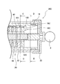
- FIG. 1 is an axial sectional view of a linear actuator according to a first embodiment of the present invention in a contracted state.
- 2A is an enlarged view of a main part of FIG. 2B is a cross-sectional view taken along the line AA in FIG. 2A.
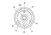
- 2C is a cross-sectional view taken along the line BB in FIG. 2A.
- FIG. 3A is an enlarged view of a main part of an axial sectional view in a contracted state of a linear actuator according to a second embodiment of the present invention.
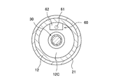
- 3B is a cross-sectional view taken along the line CC in FIG. 3A.
- 3C is a cross-sectional view taken along the line DD in FIG. 3A.
- FIG. 4A is an enlarged view of an essential part of an axial sectional view of a linear actuator according to a third embodiment of the present invention in a contracted state.
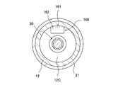
- 4B is a cross-sectional view taken along line EE in FIG. 4A.
- FIG. 1 is an axial cross-sectional view of the linear actuator 100 in a contracted state
- FIG. 2A is an enlarged view of a main part of FIG. 1
- FIG. 2B is a cross-sectional view along AA in FIG. 2A
- FIG. 2B is a sectional view taken along line BB in FIG. 2A.
- the linear actuator 100 is fixed to the end of the first tube 10 as a main body, the second tube 20 slidably provided on the outer periphery of the first tube 10, and the permanent magnet 31. And a yoke 40 that is provided so as to be fitted in the first tube 10 and holds the coil 41 facing the permanent magnet 31.
- a thrust (electromagnetic force) for driving the rod 30 in the axial direction is generated according to the current flowing in the coil 41, and the first tube 10 and the second tube 20 are relatively displaced based on this thrust.
- the linear actuator 100 expands and contracts from the most contracted position shown in FIG.
- the first tube 10 includes a cylindrical base portion 11, an inner tube 12 fixed to one end of the base portion 11, and a guide tube 13 fixed to the other end of the base portion 11.
- the base part 11 is a cylindrical member that is open at both ends.
- a pair of trunnion shafts 1 projecting in the radial direction are fixed to the outer periphery of the base portion 11.
- the linear actuator 100 is rotatably supported with respect to the external member by pivotally supporting the pair of trunnion shafts 1 on an external member (not shown).
- the second tube 20 includes a cylindrical outer tube 21 that is open at both ends, and a cap 22 that is attached to one end of the outer tube 21. One end of the second tube 20 is closed by a cap 22. The other end of the second tube 20 is an open end into which the inner tube 12 of the first tube 10 is inserted.
- a connecting member 2 connected to an external member (not shown) is fixed to the outer surface of the cap 22.
- the inner tube 12 is slidably inserted inside the outer tube 21 in a state of being installed on the base portion 11.
- One end of the inner tube 12 is fitted and fixed to the inner peripheral surface 11 ⁇ / b> A of the base portion 11, and is cantilevered by the base portion 11.
- the linear actuator 100 includes a first linear guide portion 15 and a second linear guide portion 25 that support the first tube 10 and the second tube 20 so as to be capable of relative displacement in the axial direction.
- An annular first bearing 14 is provided on the outer periphery of the free end of the inner tube 12.
- the bearing surface (outer peripheral surface) 14 ⁇ / b> A of the first bearing 14 is in sliding contact with the inner peripheral surface 21 ⁇ / b> A of the outer tube 21.
- the first linear guide portion 15 includes an outer peripheral surface 12 ⁇ / b> A of the inner tube 12 and a bearing surface 14 ⁇ / b> A of the first bearing 14.
- An annular second bearing 23 is provided on the inner periphery of the outer tube 21 on the opening end side.
- the bearing surface (inner peripheral surface) 23 ⁇ / b> A of the second bearing 23 is in sliding contact with the outer peripheral surface 12 ⁇ / b> A of the inner tube 12.
- the second linear guide portion 25 includes an inner peripheral surface 21 ⁇ / b> A of the outer tube 21 and a bearing surface 23 ⁇ / b> A of the second bearing 23.
- the bearing surface 14A of the first bearing 14 is in sliding contact with the inner peripheral surface 21A of the outer tube 21.
- the bearing surface 23 ⁇ / b> A of the second bearing 23 is in sliding contact with the outer peripheral surface 12 ⁇ / b> A of the inner tube 12.
- the outer peripheral surface 12A of the inner tube 12 and the inner peripheral surface 21A of the outer tube 21 face each other through the first bearing 14 and the second bearing 23 without any gap.
- the guide tube 13 is a cylindrical member that is open at both ends.
- An annular projecting portion 13 ⁇ / b> A that projects inward is formed at the end portion of the guide tube 13 on the base portion 11 side.
- a rod guide 50 fixed to the end of the rod 30 is slidably provided in the guide tube 13.
- the rod 30 is a rod-shaped member having a hollow portion 30A.
- One end of the rod 30 is fixed to the inside of the cap 22 constituting the end of the second tube 20.
- the other end of the rod 30 is fixed to the rod guide 50 described above.
- a plurality of permanent magnets 31 are held side by side in the axial direction.
- the permanent magnet 31 is formed in a cylindrical shape and is magnetized so that the N pole and the S pole are positioned in the axial direction.
- Adjacent permanent magnets 31 are arranged so that the same poles face each other.
- a yoke 32 is provided between the adjacent permanent magnets 31. Note that the yoke 32 is not necessarily provided, and the adjacent permanent magnets 31 may contact each other.
- a cylindrical yoke 40 is provided on the inner peripheral surface 12B of the inner tube 12.
- the yoke 40 has an insertion hole 45 through which the rod 30 is inserted in the axial direction.
- a plurality of coils 41 are built in the yoke 40.
- the yoke 40 is obtained by winding a coil 41 in a space formed on a contact surface of adjacent annular members, and laminating these annular members in the axial direction and integrating them.
- the plurality of coils 41 are arranged in parallel along the axial direction so as to face the permanent magnet 31.
- the inner tube 12 is formed with an annular protrusion 12C that protrudes inward.
- the yoke 40 is inserted into the inner tube 12 so as to come into contact with the protruding portion 12C.
- the protruding portion 12C of the inner tube 12 is provided with a through hole 12D. Further, a recess 40A is provided on the end surface of the yoke 40 on the protruding portion 12C side at a position facing the through hole 12D.
- the detent member 60 includes a pin 61 and a flange-shaped attachment portion 62.
- the pin 61 is inserted into the recess 40 ⁇ / b> A provided in the yoke 40 through the through hole 12 ⁇ / b> D provided in the protrusion 12 ⁇ / b> C.
- the mounting portion 62 is attached to the protruding portion 12C by a screw (not shown). Thereby, the relative rotation between the inner tube 12 and the yoke 40 is prevented by the rotation preventing member 60.
- the rotation prevention member 60 is attached to the protrusion part 12C with a screw, it is not restricted to this, You may attach to the protrusion part 12C by adhesion
- the rotation preventing member 60 may be a member that directly attaches the pin 61 to the projecting portion 12 ⁇ / b> C without providing the attaching portion 62.
- the pin 61 is not limited to a cylindrical shape, and may be a prismatic shape or a hollow shape.
- the rotation preventing member 60 is attached to the protruding portion 12C, but may be attached to the base portion 11 or the end portion of the inner tube 12 on the base portion 11 side. Alternatively, the anti-rotation member 60 may be attached to both of them.
- a plurality of grooves 42 are provided on the outer peripheral surface of the yoke 40 in the axial direction.
- wirings 44 from the plurality of coils 41 are accommodated.
- channel 42 is provided in three places, it is not restricted to this, Arbitrary numbers, such as four places, can be provided.
- the cross-sectional shape of the groove 42 is not limited to the arc shape, and may be a triangular shape or a quadrangular shape.
- the groove 42 may be provided on the inner peripheral surface 12 ⁇ / b> B of the inner tube 12 instead of the configuration in which the groove 42 is provided on the outer peripheral surface of the yoke 40.
- the grooves 42 may be provided on both the outer peripheral surface of the yoke 40 and the inner peripheral surface 12B of the inner tube 12.
- the wiring 44 from the plurality of coils 41 is drawn out through the groove 42 and the opening 11 ⁇ / b> B provided in the base portion 11.
- the wiring 44 drawn out to the outside is connected to a controller (not shown).
- the controller controls the thrust generated by the linear actuator 100 and the thrust generation direction (stretching direction) by controlling the magnitude and phase of the current supplied to the coil 41.
- the linear actuator 100 when a current in a predetermined direction is supplied to the coil 41, a thrust force that drives the rod 30 in one direction (rightward in FIG. 1) is generated.
- the rod 30 is driven in one direction, the outer tube 21 of the second tube 20 moves while sliding with respect to the inner tube 12 of the first tube 10, and the linear actuator 100 extends.
- the rod guide 50 comes into contact with the side surface of the protruding portion 13A, and further movement of the rod 30 is restricted.
- the protruding portion 13A functions as a stopper portion.
- the open end of the outer tube 21 comes into contact with the end of the base portion 11, and further movement of the rod 30 is restricted.
- the open end of the outer tube 21 functions as a stopper portion.
- the rotation preventing member 60 is attached to the inner tube 12, and the pin 61 of the rotation preventing member 60 is inserted into the recess 40 ⁇ / b> A provided in the yoke 40, so that vibration is generated by the operation of the linear actuator 100.
- the yoke 40 does not rotate with respect to the first tube 10.
- the anti-rotation member 60 is attached to the inner tube 12, and the pin 61 of the anti-rotation member 60 is inserted into the recess 40A provided in the yoke 40. Thereby, relative rotation between the first tube 10 and the yoke 40 can be prevented.
- FIG. 3A is an enlarged view of an essential part of an axial sectional view in a contracted state of a linear actuator according to a second embodiment of the present invention
- FIG. 3B is a CC sectional view in FIG. 3A
- FIG. It is DD sectional drawing in FIG. 3A.
- the second embodiment is different from the first embodiment in that the pin 161 is inserted into the groove 42 instead of the recess 40A.
- the anti-rotation member 160 includes a pin 161 and a flange-shaped attachment portion 162.
- the pin 161 of the rotation preventing member 160 is inserted into the groove 42 provided on the outer periphery of the yoke 40 through the through hole 12D provided in the protruding portion 12C.
- the anti-rotation member 160 has an attachment portion 162 attached to the protruding portion 12C by a screw (not shown). Thereby, relative rotation between the inner tube 12 and the yoke 40 is prevented by the rotation preventing member 160.
- the rotation preventing member 160 may be one that directly attaches the pin 161 to the protruding portion 12C without providing the attachment portion 162. Further, the rotation preventing member 160 is attached to the protruding portion 12C by a screw, but is not limited thereto, and may be attached to the protruding portion 12C by adhesion, welding, press fitting, or the like.
- the pin 161 is not limited to a cylindrical shape, but may be a prismatic shape, a hollow shape, or the same shape as the cross section of the groove 42.
- the groove 42 in which the wiring 44 from the coil 41 is accommodated is used as a recess into which the pin 161 is inserted, it is not necessary to provide the yoke 40 with a recess into which the pin 161 is inserted. Therefore, the man-hour for processing a recessed part can be reduced. In addition, since no new recess is formed in the yoke 40, the influence on the magnetic characteristics of the yoke 40 is reduced.
- FIG. 4A is an enlarged view of a principal part of an axial sectional view in a contracted state of a linear actuator according to a third embodiment of the present invention
- FIG. 4B is an EE sectional view in FIG. 4A.
- the groove 213 is provided in the inner peripheral surface 12B of the inner tube 12, and the pin 161 is inserted into the space 270 formed by the groove 42 provided in the yoke 40 and the groove 213 provided in the inner tube 12. This is different from the second embodiment.
- the inner circumferential surface 12B of the inner tube 12 is provided with a plurality of grooves 213 in the axial direction.
- the groove 213 is provided at a position facing the groove 42 provided in the yoke 40.
- the anti-rotation member 260 includes a pin 261 and a flange-shaped attachment portion 262.
- the pin 261 of the rotation preventing member 260 is inserted into the space 270 formed by the groove 42 provided in the yoke 40 and the groove 213 provided in the inner tube 12 through the through hole 12D provided in the protruding portion 12C. Is done.
- the anti-rotation member 260 has an attachment portion 262 attached to the protruding portion 12C with a screw (not shown). Thereby, the relative rotation between the inner tube 12 and the yoke 40 is prevented by the rotation preventing member 260.
- the groove 213 penetrates the protruding portion 12C and is formed so as to communicate the space 280 formed by the inner tube 12 and the outer tube 21 with the internal space 11C of the base portion 11.
- the linear actuator 300 configured as described above, when the linear actuator 300 extends, the air in the internal space 11C of the base portion 11 is sucked into the space 280 through the groove 213.
- the linear actuator 300 contracts, air is discharged from the space 280 through the groove 213 to the internal space 11 ⁇ / b> C of the base portion 11. Therefore, the groove 213 functions as a respiratory passage.
- channel 213 are provided in three places, it is not restricted to this, Arbitrary numbers, such as four places, can be provided.
- channel 213 is not restricted to circular arc shape, A triangle shape and square shape may be sufficient.
- the pin 261 is not limited to a cylindrical shape, but may be a prismatic shape, a hollow shape, or a shape that is the same as the cross section of the space 270.
- the pin 261 is inserted into the space 270 formed by the groove 42 provided in the yoke 40 and the groove 213 provided in the inner tube 12, the pin 161 is inserted into the space formed only by the groove 42.
- the pins 261 can be made thicker than those. Thereby, since the strength of the pin 261 is improved, the reliability of the anti-rotation member 260 is improved.
- the wiring 44 is located in the space 270 formed by the groove 42 and the groove 213, so that the wiring 44 is not caught on the inner peripheral surface of the inner tube 12 and is smooth. Can be inserted into. Furthermore, since the groove 213 functions as a respiratory passage, the operation reliability of the linear actuator 300 is further improved.
Landscapes
- Engineering & Computer Science (AREA)
- Power Engineering (AREA)
- Physics & Mathematics (AREA)
- Chemical & Material Sciences (AREA)
- Combustion & Propulsion (AREA)
- Electromagnetism (AREA)
- Linear Motors (AREA)
Priority Applications (2)
| Application Number | Priority Date | Filing Date | Title |
|---|---|---|---|
| US15/518,788 US20170250597A1 (en) | 2014-10-29 | 2015-10-27 | Linear actuator |
| EP15855360.2A EP3214744A4 (en) | 2014-10-29 | 2015-10-27 | Linear actuator |
Applications Claiming Priority (2)
| Application Number | Priority Date | Filing Date | Title |
|---|---|---|---|
| JP2014220169A JP5965963B2 (ja) | 2014-10-29 | 2014-10-29 | リニアアクチュエータ |
| JP2014-220169 | 2014-10-29 |
Publications (1)
| Publication Number | Publication Date |
|---|---|
| WO2016068144A1 true WO2016068144A1 (ja) | 2016-05-06 |
Family
ID=55857479
Family Applications (1)
| Application Number | Title | Priority Date | Filing Date |
|---|---|---|---|
| PCT/JP2015/080280 Ceased WO2016068144A1 (ja) | 2014-10-29 | 2015-10-27 | リニアアクチュエータ |
Country Status (4)
| Country | Link |
|---|---|
| US (1) | US20170250597A1 (https=) |
| EP (1) | EP3214744A4 (https=) |
| JP (1) | JP5965963B2 (https=) |
| WO (1) | WO2016068144A1 (https=) |
Families Citing this family (1)
| Publication number | Priority date | Publication date | Assignee | Title |
|---|---|---|---|---|
| KR102790979B1 (ko) * | 2023-03-06 | 2025-04-04 | 주식회사 팔복인더스트리 | 진동 저감형 리니어 액추에이터 |
Citations (3)
| Publication number | Priority date | Publication date | Assignee | Title |
|---|---|---|---|---|
| JP2002345184A (ja) * | 2001-05-17 | 2002-11-29 | Tsurumi Mfg Co Ltd | 水中モータにおけるステータコアの回り止め構造 |
| JP2005020903A (ja) * | 2003-06-26 | 2005-01-20 | Tanashin Denki Co | 可動磁石型リニアモータ用のコイル配線部材 |
| JP2012065452A (ja) * | 2010-09-16 | 2012-03-29 | Kayaba Ind Co Ltd | リニアアクチュエータ |
-
2014
- 2014-10-29 JP JP2014220169A patent/JP5965963B2/ja active Active
-
2015
- 2015-10-27 EP EP15855360.2A patent/EP3214744A4/en not_active Withdrawn
- 2015-10-27 US US15/518,788 patent/US20170250597A1/en not_active Abandoned
- 2015-10-27 WO PCT/JP2015/080280 patent/WO2016068144A1/ja not_active Ceased
Patent Citations (3)
| Publication number | Priority date | Publication date | Assignee | Title |
|---|---|---|---|---|
| JP2002345184A (ja) * | 2001-05-17 | 2002-11-29 | Tsurumi Mfg Co Ltd | 水中モータにおけるステータコアの回り止め構造 |
| JP2005020903A (ja) * | 2003-06-26 | 2005-01-20 | Tanashin Denki Co | 可動磁石型リニアモータ用のコイル配線部材 |
| JP2012065452A (ja) * | 2010-09-16 | 2012-03-29 | Kayaba Ind Co Ltd | リニアアクチュエータ |
Non-Patent Citations (1)
| Title |
|---|
| See also references of EP3214744A4 * |
Also Published As
| Publication number | Publication date |
|---|---|
| EP3214744A1 (en) | 2017-09-06 |
| US20170250597A1 (en) | 2017-08-31 |
| EP3214744A4 (en) | 2018-05-30 |
| JP2016086618A (ja) | 2016-05-19 |
| JP5965963B2 (ja) | 2016-08-10 |
Similar Documents
| Publication | Publication Date | Title |
|---|---|---|
| JP5530319B2 (ja) | リニアアクチュエータ | |
| JP5927266B2 (ja) | リニアアクチュエータ | |
| JP5927058B2 (ja) | リニアアクチュエータ及び溝加工方法 | |
| US9525329B2 (en) | Linear actuator | |
| JP2012065451A (ja) | リニアアクチュエータ | |
| JP5927063B2 (ja) | リニアアクチュエータ及びリニアアクチュエータのチューブ組立方法 | |
| JP5933379B2 (ja) | リニアアクチュエータ | |
| JP5965963B2 (ja) | リニアアクチュエータ | |
| JP6585894B2 (ja) | リニアアクチュエータ | |
| JP6364317B2 (ja) | リニアアクチュエータ | |
| JP5948391B2 (ja) | リニアアクチュエータ | |
| JP6360774B2 (ja) | リニアアクチュエータ | |
| JP5948390B2 (ja) | リニアアクチュエータ | |
| WO2017047388A1 (ja) | リニアモータ及びそれを備えるリニアアクチュエータ |
Legal Events
| Date | Code | Title | Description |
|---|---|---|---|
| 121 | Ep: the epo has been informed by wipo that ep was designated in this application |
Ref document number: 15855360 Country of ref document: EP Kind code of ref document: A1 |
|
| WWE | Wipo information: entry into national phase |
Ref document number: 15518788 Country of ref document: US |
|
| NENP | Non-entry into the national phase |
Ref country code: DE |
|
| REEP | Request for entry into the european phase |
Ref document number: 2015855360 Country of ref document: EP |