WO2016067815A1 - Conditionneur d'air - Google Patents
Conditionneur d'air Download PDFInfo
- Publication number
- WO2016067815A1 WO2016067815A1 PCT/JP2015/077564 JP2015077564W WO2016067815A1 WO 2016067815 A1 WO2016067815 A1 WO 2016067815A1 JP 2015077564 W JP2015077564 W JP 2015077564W WO 2016067815 A1 WO2016067815 A1 WO 2016067815A1
- Authority
- WO
- WIPO (PCT)
- Prior art keywords
- compressor
- air conditioner
- refrigerant gas
- detection sensor
- abnormality
- Prior art date
Links
Images


Classifications
-
- F—MECHANICAL ENGINEERING; LIGHTING; HEATING; WEAPONS; BLASTING
- F24—HEATING; RANGES; VENTILATING
- F24F—AIR-CONDITIONING; AIR-HUMIDIFICATION; VENTILATION; USE OF AIR CURRENTS FOR SCREENING
- F24F11/00—Control or safety arrangements
- F24F11/30—Control or safety arrangements for purposes related to the operation of the system, e.g. for safety or monitoring
- F24F11/32—Responding to malfunctions or emergencies
- F24F11/36—Responding to malfunctions or emergencies to leakage of heat-exchange fluid
-
- F—MECHANICAL ENGINEERING; LIGHTING; HEATING; WEAPONS; BLASTING
- F25—REFRIGERATION OR COOLING; COMBINED HEATING AND REFRIGERATION SYSTEMS; HEAT PUMP SYSTEMS; MANUFACTURE OR STORAGE OF ICE; LIQUEFACTION SOLIDIFICATION OF GASES
- F25B—REFRIGERATION MACHINES, PLANTS OR SYSTEMS; COMBINED HEATING AND REFRIGERATION SYSTEMS; HEAT PUMP SYSTEMS
- F25B13/00—Compression machines, plants or systems, with reversible cycle
-
- F—MECHANICAL ENGINEERING; LIGHTING; HEATING; WEAPONS; BLASTING
- F25—REFRIGERATION OR COOLING; COMBINED HEATING AND REFRIGERATION SYSTEMS; HEAT PUMP SYSTEMS; MANUFACTURE OR STORAGE OF ICE; LIQUEFACTION SOLIDIFICATION OF GASES
- F25B—REFRIGERATION MACHINES, PLANTS OR SYSTEMS; COMBINED HEATING AND REFRIGERATION SYSTEMS; HEAT PUMP SYSTEMS
- F25B49/00—Arrangement or mounting of control or safety devices
- F25B49/02—Arrangement or mounting of control or safety devices for compression type machines, plants or systems
- F25B49/022—Compressor control arrangements
-
- F—MECHANICAL ENGINEERING; LIGHTING; HEATING; WEAPONS; BLASTING
- F25—REFRIGERATION OR COOLING; COMBINED HEATING AND REFRIGERATION SYSTEMS; HEAT PUMP SYSTEMS; MANUFACTURE OR STORAGE OF ICE; LIQUEFACTION SOLIDIFICATION OF GASES
- F25B—REFRIGERATION MACHINES, PLANTS OR SYSTEMS; COMBINED HEATING AND REFRIGERATION SYSTEMS; HEAT PUMP SYSTEMS
- F25B2400/00—General features or devices for refrigeration machines, plants or systems, combined heating and refrigeration systems or heat-pump systems, i.e. not limited to a particular subgroup of F25B
- F25B2400/12—Inflammable refrigerants
-
- F—MECHANICAL ENGINEERING; LIGHTING; HEATING; WEAPONS; BLASTING
- F25—REFRIGERATION OR COOLING; COMBINED HEATING AND REFRIGERATION SYSTEMS; HEAT PUMP SYSTEMS; MANUFACTURE OR STORAGE OF ICE; LIQUEFACTION SOLIDIFICATION OF GASES
- F25B—REFRIGERATION MACHINES, PLANTS OR SYSTEMS; COMBINED HEATING AND REFRIGERATION SYSTEMS; HEAT PUMP SYSTEMS
- F25B2500/00—Problems to be solved
- F25B2500/22—Preventing, detecting or repairing leaks of refrigeration fluids
- F25B2500/222—Detecting refrigerant leaks
-
- F—MECHANICAL ENGINEERING; LIGHTING; HEATING; WEAPONS; BLASTING
- F25—REFRIGERATION OR COOLING; COMBINED HEATING AND REFRIGERATION SYSTEMS; HEAT PUMP SYSTEMS; MANUFACTURE OR STORAGE OF ICE; LIQUEFACTION SOLIDIFICATION OF GASES
- F25B—REFRIGERATION MACHINES, PLANTS OR SYSTEMS; COMBINED HEATING AND REFRIGERATION SYSTEMS; HEAT PUMP SYSTEMS
- F25B2600/00—Control issues
- F25B2600/02—Compressor control
-
- F—MECHANICAL ENGINEERING; LIGHTING; HEATING; WEAPONS; BLASTING
- F25—REFRIGERATION OR COOLING; COMBINED HEATING AND REFRIGERATION SYSTEMS; HEAT PUMP SYSTEMS; MANUFACTURE OR STORAGE OF ICE; LIQUEFACTION SOLIDIFICATION OF GASES
- F25B—REFRIGERATION MACHINES, PLANTS OR SYSTEMS; COMBINED HEATING AND REFRIGERATION SYSTEMS; HEAT PUMP SYSTEMS
- F25B2600/00—Control issues
- F25B2600/11—Fan speed control
Definitions
- the present invention relates to an air conditioner in which a flammable refrigerant is used.
- Refrigerant gas detection sensor may deteriorate when it comes into contact with high concentration refrigerant. Therefore, if the operation is started without replacing the refrigerant gas detection sensor after the gas leakage is detected by the refrigerant gas detection sensor and the operation is stopped, the refrigerant gas detection sensor may not be able to properly detect the gas leakage.
- an object of the present invention is to provide an air conditioner that can prevent the operation from being continued in a state where the refrigerant gas detection sensor is deteriorated.
- An air conditioner is an air conditioner that includes an outdoor unit having a compressor and an indoor unit connected to the outdoor unit, and uses a combustible refrigerant, and includes a refrigerant gas detection sensor, Control means for stopping the compressor when an abnormality occurs when the refrigerant gas is detected by the refrigerant gas detection sensor in a state where the compressor is in operation, and the control means includes the refrigerant After the compressor is stopped when refrigerant gas is detected by the gas detection sensor, the operation of the compressor is not started until an operation for canceling the abnormality is performed.
- An air conditioner according to a second aspect of the present invention is the air conditioner according to the first aspect of the invention, further comprising notification means for notifying that the abnormality has occurred, wherein the notification means is operated to cancel the abnormality. It is characterized by continuing notification until.
- An air conditioner according to a third aspect of the present invention is the air conditioner according to the first or second aspect of the invention, further comprising a controller that performs an operation on the operation of the air conditioner, and the operation for canceling the abnormality is performed on the controller. It is a special operation.
- the operation for canceling the abnormality is a special operation for the controller, so the refrigerant gas detection sensor is not replaced. Thus, it is possible to prevent the user from performing an operation to cancel the abnormality.
- the refrigerant gas detection sensor since the operation of the compressor is not started until the operation for canceling the abnormality is performed after the compressor is stopped by detecting the refrigerant gas by the refrigerant gas detection sensor, the refrigerant gas detection sensor It is possible to prevent the operation of the air conditioner from being continued in a state where the air conditioner has deteriorated.
- the compressor when the compressor is stopped by detecting the refrigerant gas by the refrigerant gas detection sensor, it is notified that an abnormality has occurred, and the notification is continued until the abnormality is canceled. It is possible to inform the user that the operation of the compressor is not started due to the occurrence of an abnormality.
- the operation for canceling the abnormality is a special operation for the controller, so the refrigerant gas detection sensor is not replaced. Thus, it is possible to prevent the user from performing an operation to cancel the abnormality.
- FIG. 5 is a cross-sectional view taken along line VV shown in FIG. 3. It is a perspective view when the front panel is removed from the indoor unit. It is a figure which shows the control block of an indoor unit. It is a figure explaining operation
- the air conditioner of the present embodiment includes a compressor 1, a four-way switching valve 2 having a discharge side of the compressor 1 connected to one end, and one end at the other end of the four-way switching valve 2.
- the connected outdoor heat exchanger 3, the electric expansion valve 4 having one end connected to the other end of the outdoor heat exchanger 3, and the other end of the electric expansion valve 4 having one end via a closing valve 12 and a communication pipe L ⁇ b> 1.
- One end of the connected indoor heat exchanger 5 is connected to the other end of the indoor heat exchanger 5 via the closing valve 13, the connecting pipe L 2, and the four-way switching valve 2, and the other end is connected to the suction side of the compressor 1.
- an accumulator 6 connected thereto.
- the compressor 1, the four-way switching valve 2, the outdoor heat exchanger 3, the electric expansion valve 4, the indoor heat exchanger 5 and the accumulator 6 constitute a refrigerant circuit.
- the air conditioner also includes an outdoor fan 7 disposed in the vicinity of the outdoor heat exchanger 3 and an indoor fan 8 disposed in the vicinity of the indoor heat exchanger 5.
- the compressor 1, the four-way switching valve 2, the outdoor heat exchanger 3, the electric expansion valve 4, the accumulator 6, and the outdoor fan 7 are disposed in the outdoor unit 10, and the indoor heat exchanger 5 and the indoor fan 8 are Are arranged in the indoor unit 20.
- the high-pressure refrigerant discharged from the compressor 1 passes through the four-way switching valve 2 to the room. Enters heat exchanger 5.
- the refrigerant condensed in the indoor heat exchanger 5 enters the outdoor heat exchanger 3 after being decompressed by the electric expansion valve 4.
- the refrigerant evaporated in the outdoor heat exchanger 3 returns to the suction side of the compressor 1 through the four-way switching valve 2 and the accumulator 6.
- the refrigerant circulates through the refrigerant circuit constituted by the compressor 1, the indoor heat exchanger 5, the electric expansion valve 4, the outdoor heat exchanger 3, and the accumulator 6, and the refrigeration cycle is executed.
- the indoor fan 8 heats the room by circulating the room air through the indoor heat exchanger 5.
- the high-pressure refrigerant discharged from the compressor 1 is four-way.
- the outdoor heat exchanger 3 is entered through the switching valve 2.
- the refrigerant condensed in the outdoor heat exchanger 3 is reduced in pressure by the electric expansion valve 4 and then enters the indoor heat exchanger 5.
- the refrigerant evaporated in the indoor heat exchanger 5 returns to the suction side of the compressor 1 through the four-way switching valve 2 and the accumulator 6.
- a flammable refrigerant in this air conditioner, a flammable refrigerant is used.
- the “flammable refrigerant” includes a flammable refrigerant and a slightly flammable refrigerant.
- R32 which is a slightly flammable refrigerant is used, but R290 may be used, for example.
- a refrigerant having a specific gravity greater than that of air is used.
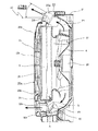
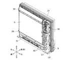
- the indoor unit 20 is a floor-standing indoor unit, and is attached to the front side of the bottom frame 21 and a substantially rectangular bottom frame 21 whose rear side is attached to the wall surface of the room.
- a front grille 22 having a substantially rectangular opening 22c on the front surface, and a front panel 23 attached to cover the opening 22c of the front grill 22.
- a casing 20 a is formed by the bottom frame 21, the front grille 22, and the front panel 23.
- An upper air outlet 22 a is provided in the upper part of the front grill 22, and a lower air outlet 22 b is provided in the lower part of the front grill 22.
- An upper and lower flap 24 that changes the airflow direction of the airflow blown from the upper air outlet 22a in the vertical direction is provided in the upper air outlet passage P1 that communicates with the upper air outlet 22a.
- a flap motor 24 a (see FIG. 7) is connected to the upper and lower flaps 24.
- the upper and lower flaps 24 can be rotated around a rotation axis along the horizontal direction by driving a flap motor 24a.
- the upper and lower flaps 24 rotate in the vertical air direction control range shown in FIG. 4 and blow out cold air or warm air forward and obliquely upward from the upper air outlet 22a.
- the upper air outlet 22a is closed as shown in FIG.
- a display unit 52 is provided on the upper portion of the front grill 22.
- the display unit 52 displays the operation state of the indoor unit 20, and when the operation is stopped due to leakage of refrigerant gas in the indoor unit 20, information indicating that the operation has been stopped due to an abnormality is displayed. .
- the shutter 30 that opens and closes the lower outlet 22b and the airflow direction of the airflow blown from the lower outlet 22b in the left-right direction are changed.
- Left and right flaps 31 are arranged.
- a shutter motor 30 b is connected to the shutter 30. As shown in FIG. 4, the shutter 30 rotates around a shaft 30a along the horizontal direction by driving the shutter motor 30b.
- the shutter 30 stops at the position A indicated by the alternate long and short dash line, opens the lower outlet 22b, stops at the position B indicated by the alternate long and short dashed line, and closes the lower outlet 22b.
- the left and right flaps 31 are manually adjusted in the direction of the flaps.
- an upper suction port 23a is provided on the upper side of the front panel 23
- a lower suction port 23b is provided on the lower side of the front panel 23
- lateral sides are provided on the left and right side surfaces of the front panel 23.
- a suction port 23c (only the right side is shown in FIG. 2) is provided.
- a fan motor 26 is fixed substantially at the center of the bottom frame 21.
- the indoor fan 8 to which the shaft of the fan motor 26 is connected is disposed on the bottom frame 21 so that the shaft is in the front-rear direction.
- the indoor fan 8 is a turbo fan that blows air sucked from the front side outward in the radial direction with respect to the shaft.
- the bottom frame 21 has a bell mouth 27 formed on the front side of the indoor fan 8.
- the indoor heat exchanger 5 is disposed on the front side of the bell mouth 27, and the front grill 22 is attached to the front side of the indoor heat exchanger 5.
- a front panel 23 is attached to the front side of the front grill 22.
- a filter 25 is attached to the opening 22 c of the front grill 22.
- the fan motor 26 is driven and the indoor fan 8 is rotated. Then, the room air is sucked into the indoor unit 20 from the upper suction port 23a, the lower suction port 23b, and the side suction port 23c by the rotation of the indoor fan 8, and is sucked into the indoor unit 20. After the heat is exchanged in the indoor heat exchanger 5, the air is blown out into the room from the upper outlet 22a and the lower outlet 22b. When the shutter 30 closes the lower air outlet 22b, the room air sucked into the indoor unit 20 is blown out only from the upper air outlet 22a.
- a drain pan 28 for receiving and draining condensed water from the air generated in the indoor heat exchanger 5 is disposed below the indoor heat exchanger 5.
- an electrical component box 50 is disposed on the right outside (longitudinal direction outside) and above the indoor heat exchanger 5.
- a refrigerant gas detection sensor 9 is detachably attached below the electrical component box 50. The refrigerant gas detection sensor 9 is disposed on the right outside (longitudinal direction outside) of the indoor heat exchanger 5 and the drain pan 28.
- the refrigerant gas having a specific gravity greater than that of the air flows downward and reaches the drain pan 28. Since the refrigerant gas that has reached the drain pan 28 flows from the left end side to the right end side of the drain pan 28, the refrigerant gas that has reached the drain pan 28 tends to overflow from the drain pan 28 on the refrigerant gas detection sensor 9 side in the longitudinal direction. The overflowing refrigerant gas stays at the bottom of the indoor unit 20 and leaks from the indoor unit 20 to the outside.
- a control unit 51 is housed in the electrical component box 50, and controls each component necessary for air conditioning operation and the like of the air conditioner. As shown in FIG. 7, the fan motor 26, the refrigerant gas detection sensor 9, the flap motor 24 a, the shutter motor 30 b, the compressor 1, the display unit 52, and the controller 53 are connected to the control unit 51.
- the control unit 51 controls the indoor fan 8, the upper and lower flaps 24, and the shutter 30, determines the presence or absence of refrigerant leakage based on the detection result of the refrigerant gas detected by the refrigerant gas detection sensor 9, Is detected, the compressor 1 is stopped or the display unit 52 displays that there is an abnormality.
- the controller 53 performs, for example, an operation for starting / stopping the operation of the air conditioner or an operation for canceling an abnormality when the operation is abnormally stopped due to refrigerant leakage, and the operation content is supplied to the control unit 51. Is done.
- the abnormality canceling operation for the controller 53 is an abnormality canceling operation indicating that the refrigerant gas detection sensor has been replaced, and the abnormality canceling operation is performed by the user without replacing the refrigerant gas detection sensor 9. In order to prevent this, for example, it is a special operation dedicated to a service person for an air conditioner.
- the special operation may be, for example, an operation that is not performed by the user's normal operation (for example, a long press of the operation button) or an operation that is not performed by the user's normal operation (for example, a long press of the operation button).
- An operation that can be performed after switching the screen of the controller 53 can be considered. Therefore, in the air conditioner of this embodiment, even when the operation is abnormally stopped due to refrigerant leakage, even if the breaker of the power source to which the air conditioner is connected is turned off, The operation of the compressor 1 is not started until an abnormality canceling operation for the controller 53 is performed.
- the refrigerant gas detection sensor 9 is a sensor that detects leaked refrigerant gas, and is disposed at the same height as the drain pan 28 or below the drain pan 28 as shown in FIG. Further, the drain pan 28 is disposed on the right outer side (longitudinal direction outer side) and on the back (rear side) of the drain pan 28 and the indoor heat exchanger 5.
- a semiconductor sensor, a contact combustion sensor, an electrochemical sensor, or the like is used as the refrigerant gas detection sensor.
- step S1 when the air conditioner is in operation, the presence or absence of refrigerant leakage is repeatedly determined based on the detection result of the refrigerant gas detected by the refrigerant gas detection sensor 9 (step S1). If it is determined that a refrigerant leak has been detected (S1: YES), the compressor is stopped as an abnormality (step S2), and the fact that the compressor has been stopped due to an abnormality is displayed on the display unit 52 (step S3).
- step S4 when the compressor is stopped as an abnormality, the operation of the compressor 1 is not started until the refrigerant gas detection sensor 9 is replaced. It is repeatedly determined whether or not an abnormality canceling operation has been performed (step S4). If it is determined that an abnormality canceling operation has been performed on the controller 53 (S4: YES), it is not displayed on the display unit 52 that the compressor has been stopped due to an abnormality (step S5).
- step S6 it is repeatedly determined whether or not the operation start operation has been performed on the controller 53 (step S6). If it is determined that the operation start operation has been performed (S6: YES), the operation of the compressor is started (step S7).
- the air conditioner of this embodiment has the following characteristics.
- the operation of the compressor 1 is not started until the operation for canceling the abnormality is performed after the compressor 1 is stopped by detecting the refrigerant gas by the refrigerant gas detection sensor 9. Therefore, it is possible to prevent the operation of the air conditioner from being continued in a state where the refrigerant gas detection sensor 9 has deteriorated.
- the compressor 1 when the compressor 1 is stopped by detecting the refrigerant gas by the refrigerant gas detection sensor 9, it is displayed on the display unit 52 that an abnormality has occurred. Since the operation is continued until the abnormality canceling operation is performed on 53, it is possible to notify the user that the operation of the compressor 1 is not started due to the occurrence of the abnormality.
- the abnormality canceling operation is a special operation for the controller 53. It is possible to prevent the user from performing an abnormality canceling operation without replacing the refrigerant gas detection sensor 9.
- the case where the operation of the compressor is not started after the refrigerant gas is detected by the refrigerant gas detection sensor and the compressor is stopped until the abnormality is released to the controller is described.
- the abnormality canceling operation indicating that the detection sensor has been replaced is not limited to the operation on the controller.
- the case where an abnormality has occurred when refrigerant leakage is detected is displayed on the display unit, and the display is continued until the abnormality is canceled.
- an abnormality has occurred. It may be notified by a method different from the display, or may not be notified that an abnormality has occurred.
- the abnormality canceling operation is a special operation for the controller.
- the special operation method may be changed.
- the refrigerant gas detection sensor is arranged in the indoor unit, but the present invention is not limited to this. Therefore, the refrigerant gas detection sensor may be arranged in the outdoor unit, and the effect of the present invention can be obtained in the air conditioner having the refrigerant gas detection sensor.
- the indoor unit may be an indoor unit other than the floor-standing indoor unit or a wall-mounted indoor unit.
- the present invention it is possible to prevent the operation from being continued in a state where the gas leak detection sensor is deteriorated.
Landscapes
- Engineering & Computer Science (AREA)
- Mechanical Engineering (AREA)
- General Engineering & Computer Science (AREA)
- Physics & Mathematics (AREA)
- Thermal Sciences (AREA)
- Chemical & Material Sciences (AREA)
- Combustion & Propulsion (AREA)
- Air Conditioning Control Device (AREA)
Abstract
La présente invention concerne un conditionneur d'air pouvant continuer à fonctionner même lorsqu'un capteur de détection de fuite de gaz se détériore. Le présent conditionneur d'air est équipé d'une unité extérieure comportant un compresseur et d'une unité intérieure reliée à l'unité extérieure, fait intervenir un réfrigérant inflammable et est en outre équipé d'un capteur de détection de gaz réfrigérant et d'une unité de commande permettant l'arrêt du compresseur lorsque le compresseur est en fonctionnement et qu'une anomalie est déterminée comme s'étant produite lors de la détection d'un gaz réfrigérant par le capteur de détection de gaz réfrigérant. En outre, l'unité de commande arrête le compresseur lorsque le capteur de détection de gaz réfrigérant détecte le gaz réfrigérant et, ensuite, ne lance le compresseur que lorsqu'une opération de suppression de l'anomalie a été effectuée.
Priority Applications (5)
| Application Number | Priority Date | Filing Date | Title |
|---|---|---|---|
| AU2015338330A AU2015338330B2 (en) | 2014-10-31 | 2015-09-29 | Air conditioner |
| EP15855188.7A EP3249311B1 (fr) | 2014-10-31 | 2015-09-29 | Conditionneur d'air |
| ES15855188T ES2773695T3 (es) | 2014-10-31 | 2015-09-29 | Acondicionador de aire |
| CN201580058212.8A CN107110541B (zh) | 2014-10-31 | 2015-09-29 | 空调机 |
| US15/522,894 US11248816B2 (en) | 2014-10-31 | 2015-09-29 | Air conditioner |
Applications Claiming Priority (2)
| Application Number | Priority Date | Filing Date | Title |
|---|---|---|---|
| JP2014223397A JP6020534B2 (ja) | 2014-10-31 | 2014-10-31 | 空気調和機 |
| JP2014-223397 | 2014-10-31 |
Publications (1)
| Publication Number | Publication Date |
|---|---|
| WO2016067815A1 true WO2016067815A1 (fr) | 2016-05-06 |
Family
ID=55857161
Family Applications (1)
| Application Number | Title | Priority Date | Filing Date |
|---|---|---|---|
| PCT/JP2015/077564 WO2016067815A1 (fr) | 2014-10-31 | 2015-09-29 | Conditionneur d'air |
Country Status (7)
| Country | Link |
|---|---|
| US (1) | US11248816B2 (fr) |
| EP (1) | EP3249311B1 (fr) |
| JP (1) | JP6020534B2 (fr) |
| CN (1) | CN107110541B (fr) |
| AU (1) | AU2015338330B2 (fr) |
| ES (1) | ES2773695T3 (fr) |
| WO (1) | WO2016067815A1 (fr) |
Families Citing this family (10)
| Publication number | Priority date | Publication date | Assignee | Title |
|---|---|---|---|---|
| US10119738B2 (en) | 2014-09-26 | 2018-11-06 | Waterfurnace International Inc. | Air conditioning system with vapor injection compressor |
| JPWO2016157538A1 (ja) * | 2015-04-03 | 2017-04-27 | 三菱電機株式会社 | 冷凍サイクル装置 |
| US11118821B2 (en) * | 2017-01-19 | 2021-09-14 | Mitsubishi Electric Corporation | Refrigeration cycle apparatus |
| JP6929747B2 (ja) * | 2017-09-25 | 2021-09-01 | 東芝キヤリア株式会社 | 空気調和機 |
| JP7085405B2 (ja) * | 2018-05-15 | 2022-06-16 | 三菱重工サーマルシステムズ株式会社 | 熱源システム、制御装置、熱源システム運転方法及びプログラム |
| US11662128B2 (en) | 2018-07-09 | 2023-05-30 | Crane Payment Innovations, Inc. | Refrigerant leak detector for a vending machine |
| US11592215B2 (en) | 2018-08-29 | 2023-02-28 | Waterfurnace International, Inc. | Integrated demand water heating using a capacity modulated heat pump with desuperheater |
| US11231198B2 (en) | 2019-09-05 | 2022-01-25 | Trane International Inc. | Systems and methods for refrigerant leak detection in a climate control system |
| JP7436784B2 (ja) * | 2019-09-30 | 2024-02-22 | ダイキン工業株式会社 | 空気調和機 |
| US11512867B2 (en) | 2020-03-12 | 2022-11-29 | Johnson Controls Tyco IP Holdings LLP | Refrigerant detection and control of HVAC system |
Citations (3)
| Publication number | Priority date | Publication date | Assignee | Title |
|---|---|---|---|---|
| JPH06180166A (ja) * | 1992-12-09 | 1994-06-28 | Toshiba Corp | 空気調和機 |
| JP2000356387A (ja) * | 1999-06-11 | 2000-12-26 | Corona Corp | 空気調和機の制御装置 |
| JP2011117655A (ja) * | 2009-12-02 | 2011-06-16 | Toshiba Carrier Corp | 空気調和機 |
Family Cites Families (11)
| Publication number | Priority date | Publication date | Assignee | Title |
|---|---|---|---|---|
| US3412570A (en) * | 1965-05-24 | 1968-11-26 | George H. Pruett Sr. | Radiation sensitive system for detecting refrigerant leaks |
| US4787212A (en) * | 1987-10-19 | 1988-11-29 | Hessey John C | Air conditioner with automatic shutdown |
| US5215643A (en) * | 1988-02-24 | 1993-06-01 | Matsushita Electric Works, Ltd. | Electrochemical gas sensor |
| JP2523191B2 (ja) * | 1989-09-01 | 1996-08-07 | 富士機械製造株式会社 | シ―ケンス制御装置 |
| JPH11230648A (ja) * | 1998-02-13 | 1999-08-27 | Matsushita Electric Ind Co Ltd | 可燃性冷媒を用いた冷凍機器の冷媒漏洩警報装置 |
| US6085530A (en) * | 1998-12-07 | 2000-07-11 | Scroll Technologies | Discharge temperature sensor for sealed compressor |
| US6907748B2 (en) * | 2003-02-28 | 2005-06-21 | Delphi Technologies, Inc. | HVAC system with refrigerant venting |
| EP2370749B1 (fr) * | 2008-11-26 | 2013-07-03 | Delphi Technologies, Inc. | Système de détection de fuite de réfrigérant |
| JP2012013348A (ja) | 2010-07-02 | 2012-01-19 | Panasonic Corp | 空気調和機 |
| JP5968629B2 (ja) | 2012-01-25 | 2016-08-10 | 株式会社クボタ | サイロおよびサイロの運転方法 |
| JP5812081B2 (ja) * | 2013-11-12 | 2015-11-11 | ダイキン工業株式会社 | 室内機 |
-
2014
- 2014-10-31 JP JP2014223397A patent/JP6020534B2/ja active Active
-
2015
- 2015-09-29 EP EP15855188.7A patent/EP3249311B1/fr active Active
- 2015-09-29 CN CN201580058212.8A patent/CN107110541B/zh active Active
- 2015-09-29 ES ES15855188T patent/ES2773695T3/es active Active
- 2015-09-29 US US15/522,894 patent/US11248816B2/en active Active
- 2015-09-29 AU AU2015338330A patent/AU2015338330B2/en active Active
- 2015-09-29 WO PCT/JP2015/077564 patent/WO2016067815A1/fr active Application Filing
Patent Citations (3)
| Publication number | Priority date | Publication date | Assignee | Title |
|---|---|---|---|---|
| JPH06180166A (ja) * | 1992-12-09 | 1994-06-28 | Toshiba Corp | 空気調和機 |
| JP2000356387A (ja) * | 1999-06-11 | 2000-12-26 | Corona Corp | 空気調和機の制御装置 |
| JP2011117655A (ja) * | 2009-12-02 | 2011-06-16 | Toshiba Carrier Corp | 空気調和機 |
Non-Patent Citations (1)
| Title |
|---|
| See also references of EP3249311A4 * |
Also Published As
| Publication number | Publication date |
|---|---|
| US11248816B2 (en) | 2022-02-15 |
| EP3249311B1 (fr) | 2019-12-04 |
| CN107110541A (zh) | 2017-08-29 |
| JP2016090111A (ja) | 2016-05-23 |
| EP3249311A1 (fr) | 2017-11-29 |
| JP6020534B2 (ja) | 2016-11-02 |
| EP3249311A4 (fr) | 2018-11-07 |
| ES2773695T3 (es) | 2020-07-14 |
| AU2015338330B2 (en) | 2017-06-22 |
| US20170328620A1 (en) | 2017-11-16 |
| CN107110541B (zh) | 2018-08-07 |
Similar Documents
| Publication | Publication Date | Title |
|---|---|---|
| JP6020534B2 (ja) | 空気調和機 | |
| US10126012B2 (en) | Air conditioner | |
| JP5804027B2 (ja) | 空気調和機の室内機 | |
| JP6248898B2 (ja) | 空気調和機 | |
| WO2016088653A1 (fr) | Climatiseur | |
| WO2016067818A1 (fr) | Unité intérieure de conditionneur d'air | |
| JP6519360B2 (ja) | 空気調和装置の室内機 | |
| WO2016067816A1 (fr) | Unité intérieure de climatiseur | |
| JP5892199B2 (ja) | 空調室内機 | |
| ES2806647T3 (es) | Acondicionador de aire | |
| JP2016125694A (ja) | 空気調和装置の室内機 | |
| JPWO2017187562A1 (ja) | 冷凍サイクル装置 | |
| JP2010145010A (ja) | 床置き形空気調和機 | |
| JP4209912B2 (ja) | 空気調和機 | |
| JP2015094512A (ja) | 床置型空気調和機の室内機 | |
| JP6914794B2 (ja) | 空気調和機 | |
| JPWO2017037841A1 (ja) | 冷凍サイクル装置及びその設置方法 | |
| JP2008116081A (ja) | 空気調和機 | |
| JP2016090112A (ja) | 空気調和機 |
Legal Events
| Date | Code | Title | Description |
|---|---|---|---|
| 121 | Ep: the epo has been informed by wipo that ep was designated in this application |
Ref document number: 15855188 Country of ref document: EP Kind code of ref document: A1 |
|
| WWE | Wipo information: entry into national phase |
Ref document number: 15522894 Country of ref document: US |
|
| NENP | Non-entry into the national phase |
Ref country code: DE |
|
| REEP | Request for entry into the european phase |
Ref document number: 2015855188 Country of ref document: EP |
|
| WWE | Wipo information: entry into national phase |
Ref document number: 2015338330 Country of ref document: AU |