WO2016063352A1 - モータ制御装置及びロボットシステム - Google Patents
モータ制御装置及びロボットシステム Download PDFInfo
- Publication number
- WO2016063352A1 WO2016063352A1 PCT/JP2014/077974 JP2014077974W WO2016063352A1 WO 2016063352 A1 WO2016063352 A1 WO 2016063352A1 JP 2014077974 W JP2014077974 W JP 2014077974W WO 2016063352 A1 WO2016063352 A1 WO 2016063352A1
- Authority
- WO
- WIPO (PCT)
- Prior art keywords
- connector
- control device
- motor control
- substrate
- wall portion
- Prior art date
- Legal status (The legal status is an assumption and is not a legal conclusion. Google has not performed a legal analysis and makes no representation as to the accuracy of the status listed.)
- Ceased
Links
Images



Classifications
-
- H—ELECTRICITY
- H01—ELECTRIC ELEMENTS
- H01R—ELECTRICALLY-CONDUCTIVE CONNECTIONS; STRUCTURAL ASSOCIATIONS OF A PLURALITY OF MUTUALLY-INSULATED ELECTRICAL CONNECTING ELEMENTS; COUPLING DEVICES; CURRENT COLLECTORS
- H01R13/00—Details of coupling devices of the kinds covered by groups H01R12/70 or H01R24/00 - H01R33/00
- H01R13/46—Bases; Cases
- H01R13/516—Means for holding or embracing insulating body, e.g. casing, hoods
-
- H—ELECTRICITY
- H01—ELECTRIC ELEMENTS
- H01R—ELECTRICALLY-CONDUCTIVE CONNECTIONS; STRUCTURAL ASSOCIATIONS OF A PLURALITY OF MUTUALLY-INSULATED ELECTRICAL CONNECTING ELEMENTS; COUPLING DEVICES; CURRENT COLLECTORS
- H01R13/00—Details of coupling devices of the kinds covered by groups H01R12/70 or H01R24/00 - H01R33/00
- H01R13/46—Bases; Cases
- H01R13/533—Bases, cases made for use in extreme conditions, e.g. high temperature, radiation, vibration, corrosive environment, pressure
-
- H—ELECTRICITY
- H01—ELECTRIC ELEMENTS
- H01R—ELECTRICALLY-CONDUCTIVE CONNECTIONS; STRUCTURAL ASSOCIATIONS OF A PLURALITY OF MUTUALLY-INSULATED ELECTRICAL CONNECTING ELEMENTS; COUPLING DEVICES; CURRENT COLLECTORS
- H01R13/00—Details of coupling devices of the kinds covered by groups H01R12/70 or H01R24/00 - H01R33/00
- H01R13/58—Means for relieving strain on wire connection, e.g. cord grip, for avoiding loosening of connections between wires and terminals within a coupling device terminating a cable
-
- H—ELECTRICITY
- H02—GENERATION; CONVERSION OR DISTRIBUTION OF ELECTRIC POWER
- H02P—CONTROL OR REGULATION OF ELECTRIC MOTORS, ELECTRIC GENERATORS OR DYNAMO-ELECTRIC CONVERTERS; CONTROLLING TRANSFORMERS, REACTORS OR CHOKE COILS
- H02P29/00—Arrangements for regulating or controlling electric motors, appropriate for both AC and DC motors
Definitions
- the disclosed embodiment relates to a motor control device and a robot system.
- Patent Document 1 includes a housing, an opening / closing panel that is rotatably supported on one side surface of the housing, and a connector that is provided on a step surface of a step portion of the opening / closing panel and is connected to a connection cable.
- a robot controller is described.
- the cable connection between the robot control device and the robot can have various connection configurations depending on the number of axes of the robot and the configuration of the external device.
- the connection configuration of the cable is uniquely determined, and it is not possible to flexibly cope with various connection configurations.
- the present invention has been made in view of such problems, and an object thereof is to provide a motor control device and a robot system that can flexibly cope with various cable connection configurations.
- a motor control device that controls a motor, the housing including a plurality of wall portions, and disposed on at least one of the wall portions, A connector to which wiring related to motor control is connected, a connector case that is fixed to the wall portion where the connector is disposed, covers the connector, is fixed to the connector case, and connects the connector case and an external device A motor control device having a cable holding member that holds an end portion of the cable to be applied is applied.
- a robot system including the motor control device and a robot controlled by the motor control device.
- a motor control apparatus which controls a motor, Comprising: The housing
- a motor control device having a connector to which wiring is connected and means for classifying the wiring connected to the connector for each cable for connecting to an external device is applied.
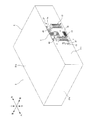
- the motor control device 1 of this embodiment is a control device that controls an external device including a motor such as an industrial robot.
- the motor control device 1 includes a device main body 2 and a connector case 4.
- the apparatus main body 2 has a substantially rectangular parallelepiped housing 21 that forms the outline thereof.
- the housing 21 includes a front wall portion 21a, a rear wall portion 21b (see FIG. 4 and the like), a left wall portion 21c, a right wall portion 21d (see FIG. 4 and the like), an upper wall portion 21e, and a lower wall portion 21f ( 4).
- the horizontal direction is also referred to as “width direction”
- the vertical direction is also referred to as “height direction”
- the front-rear direction is also referred to as “depth direction”.
- the shape of the housing 21 is not limited to a substantially rectangular parallelepiped shape, and may be another shape.
- a plurality of connectors 12, 13, 14, and 15 to which wiring related to motor control is connected are arranged near the center in the width direction of the front wall 21 a of the housing 21.
- Motor power lines for supplying power to a motor are connected to the connectors 12 and 13 (hereinafter also referred to as “first connectors 12 and 13”).
- a brake wire for outputting a signal to a brake of a motor (not shown) is connected to the connector 14 (hereinafter also referred to as “second connector 14”).
- An encoder communication line for inputting / outputting a signal to / from an encoder (not shown) is connected to the connector 15 (hereinafter also referred to as “third connector 15”).
- vent hole 5 is provided Near the central portion in the width direction of the front wall portion 21a of the housing 21, a vent hole 5 is provided.
- the vent hole 5 is substantially T-shaped, and a part thereof is disposed above the first connectors 12 and 13, and a part thereof is disposed between the first connectors 12 and 13.
- the connector case 4 is a metal substantially rectangular parallelepiped box formed smaller than the housing 21 of the apparatus main body 2, and includes a front wall 41a, a rear wall 41b (see FIG. 8), a left wall 41c, A wall 41d (see FIG. 8), an upper wall 41e, and a lower wall 41f (not shown) are provided.
- the connector case 4 is fixed to a wall portion of the housing 21 where the connector is disposed, in this example, the front wall portion 21a, and covers the connectors 12, 13, 14, and 15 while exposing the vent hole 5.
- the wall portion of the connector case 4, in this example, the front wall portion 41 a is provided with a cable holding member 7 that holds the ends of the cables 81, 82, and 83 that connect the connector case 4 and an external device. Details of the cable holding member 7 will be described later.
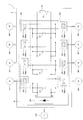
- the motor control device 1 is a kind of power conversion device that converts power input from an external power source into predetermined power and outputs it to a load. Specifically, the motor control device 1 converts AC power input from the three-phase AC power source 100 into another AC power, for example, eight three-phase AC motors M1, M2, M3, M4, M5, M6. M7 and M8 (hereinafter collectively referred to as “motor M”) to control the operation. That is, the motor control device 1 is a motor control device capable of 8-axis control.
- the robot when a 6-axis robot is controlled by the motor control device 1, for example, the robot is controlled by 6 axes out of the 8 controllable axes, and the remaining 2 axes, for example, travel of the robot, rotation of a work target work, etc. It is possible to control the attached equipment of the robot to be performed.
- the number of axes that can be controlled by the motor control device 1, that is, the number of motors M is not limited to eight, and may be any other number.
- the external power source is not limited to the three-phase AC power source, and may be another power source.
- the load is not limited to the three-phase AC motor, and may be another load.
- the motor control device 1 includes a diode module DM, for example, four capacitors C1, C2, C3, C4 (hereinafter collectively referred to as “capacitor C”), for example, eight power modules PM1, PM2, PM3, PM4, PM5, PM6. PM7, PM8 (hereinafter collectively referred to as “power module PM”), a regenerative resistor R that is an example of a resistor, and a plurality of electronic components.
- the diode module DM includes a diode, rectifies three-phase AC power input from the AC power supply 100, and outputs DC power to the DC buses P and N.
- the capacitors C1 to C4 are connected across the DC buses P and N, and smooth the DC voltage rectified by the diode module DM.
- Each of the power modules PM1 to PM8 includes a plurality of switching elements SW (only one is shown in FIG. 3) configured by semiconductor elements such as IGBTs.
- Each of the power modules PM1 to PM8 converts DC power into predetermined three-phase AC power and outputs it to the three-phase AC motors M1 to M8.
- the diodes of the diode module DM, the capacitors C1 to C4, the switching elements SW of the power modules PM1 to PM8, and the like constitute a power conversion circuit 40.
- a series circuit of the regenerative resistor R and the switch Q is connected between the DC buses P and N.
- the switch Q includes a semiconductor element such as a MOSFET, for example.
- the circuit configuration of the motor control device 1 described above is merely an example, and a circuit configuration other than the above may be used.
- the resistor is not limited to the regenerative resistor R, and may be another resistor such as a dynamic brake.
- the number of power modules PM is not limited to eight, and may be another number.
- the present invention is not limited to the case where two power modules PM are connected in parallel to one capacitor C.
- One power module PM is connected to one capacitor C, or three or more power modules PM are connected in parallel. May be connected.
- the number of capacitors C is not limited to four, and may be other numbers.
- a reactor may be installed instead of the capacitor C.
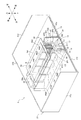
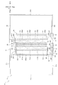
- FIGS. 4, 5, and 6 Internal structure of the device body> Next, an example of the internal structure of the device main body 2 of the motor control device 1 will be described with reference to FIGS. 4, 5, and 6. Note that the housing 21 of the apparatus main body 2 is omitted in FIG. 4 from the illustration of the upper wall portion 21e and the front wall portion 21a, in FIG. 5, the illustration of the upper wall portion 21e is omitted, and in FIG. The illustration of the front wall portion 21a is omitted. Also, in FIGS. 4 to 6, illustrations of the components other than the main part of the apparatus main body 2 are omitted as appropriate.
- the housing 21 of the apparatus body 2 includes a first substrate 30, two second substrates 32 and 34, a third substrate 36, the capacitors C1 to C4, and the power module PM1.
- a plurality of electronic components including PM8 and regenerative resistor R, three heat sinks 50, 52, 54, a fan 60, and the like are housed.
- the housing 21 is formed with two vent holes, that is, the above-described vent hole 5 for intake and the vent hole 6 for exhaust (see FIG. 5).
- the first connector 12, 13, the second connector 14, and the third connector 15 are disposed on the housing 21. In FIGS. 4 to 6, the connectors 12 to 15 are shown in a simplified manner for the sake of complexity.
- the surface of one side is the component surface 30a in which components are arrange
- the first substrate 30 has a substantially rectangular shape, and the dimension in the plate surface direction is substantially equal to the inner dimension of the lower wall portion 21f of the housing 21.
- substrate 30 is being fixed to the lower wall part 21f in the lower part in the housing 21 so that the component surface 30a may become an upper surface and the solder surface 30b may become a lower surface.
- the second substrates 32 and 34 are erected on the component surface 30a of the first substrate 30 so as to face each other via a connector or the like (not shown).
- each of the second substrates 32 and 34 has a substantially rectangular shape, and each dimension in the longitudinal direction is substantially equal to the inner dimension in the depth direction of the casing 21, and each dimension in the short direction is a height of the casing 21. A little smaller than the inner dimension in the vertical direction.
- the second substrates 32 and 34 are arranged so that the longitudinal direction of each of the first substrates 30 is along the depth direction and the short side direction is along the height direction, and the second substrate 32 and 34 are spaced apart from each other with a predetermined gap in the width direction.
- the right surface 32a of the second substrate 32 and the left surface 34a of the second substrate 34 are disposed to face each other in the width direction.
- the right surface 32a is also referred to as “opposing surface 32a”
- the left surface 34a is also referred to as “facing surface 34a”.
- the third substrate 36 is erected on the component surface 30a of the first substrate 30 via a connector or the like (not shown).
- the third substrate 36 has a substantially rectangular shape, the dimension in the longitudinal direction is substantially equal to the inner dimension in the depth direction of the casing 21, and the dimension in the short direction is the inner dimension in the height direction of the casing 21. A little smaller than the dimensions.
- the third substrate 36 has a longitudinal direction along the depth direction and a short side direction along the height direction, and is spaced apart from the second substrate 32 to the left with a predetermined gap in the width direction. 32 is arranged to face each other substantially in parallel.
- the third substrate 36 has a right surface 36 a that faces the second substrate 32.
- substrate does not need to be a single board
- the first substrate 30 is not limited to a single-sided substrate, and may be a double-sided substrate in which components are arranged on both sides, a multilayer substrate in which a plurality of substrates are stacked, or the like.
- the position of the third substrate 36 is not limited to the left side of the second substrate 32, and may be the right side of the second substrate 34 positioned on the right side.
- the vent hole 5 is formed in the vicinity of the center portion in the width direction of the front wall portion 21a so as to be disposed between the second substrates 32 and 34 in the width direction.
- the vent 6 is formed in the vicinity of the central portion in the width direction of the rear wall 21b so as to be disposed between the second substrates 32 and 34 in the width direction.
- the vents 5 and 6 are arranged to face each other in the depth direction, and communicate with a wind tunnel 70 (see FIG. 6) in the casing 21 to be described later.
- the vent 5 has a substantially center in the width direction of the front wall 21 a so as to avoid interference with the first connectors 12, 13 and the second connector 14, etc. disposed on the front wall 21 a. It is formed in a substantially T shape in a substantially upper half of the part.
- the vent hole 5 is formed in a honeycomb shape having a large number of vent holes 5a having an appropriate shape (for example, circular, hexagonal, etc.).
- the upper part of the vent hole 5 is close to the upper end of the front wall part 21a, and the lower end of the vent hole 5 is located at a substantially central part in the height direction of the front wall part 21a.
- the vent 6 is formed in a substantially square shape or a substantially circular shape.
- the vent hole 6 is also formed in a honeycomb shape like the vent hole 5.
- vent holes 5 and 6 is not limited to the above, and may be various shapes other than the T-shape such as a square shape, a circular shape, and a triangular shape.
- a plurality of vent holes 5 and 6 may be formed.
- the vent holes 5 and 6 may be formed in wall parts other than the front wall part 21a and the rear wall part 21b.
- the fan 60 is disposed inside the vent hole 6 between the second substrates 32 and 34, and a cooling channel 75 (see FIG. 6) for cooling the power modules PM1 to PM8, the capacitors C1 to C4, and the regenerative resistor R. It blows to the wind tunnel 70 (refer to the one-dot chain line in FIG. 6) including the two-dot chain line.
- the wind tunnel 70 and the cooling flow path 75 therein are formed to extend in the depth direction (details will be described later).
- the fan 60 is an exhaust fan, and the air that has been sucked into the wind tunnel 70 (inside the casing 21) from the air vent 5 by using the air vent 5 as the air inlet and the air vent 6 as the air outlet 6 To the outside of the wind tunnel 70 (outside the housing 21). Therefore, when the fan 60 blows air to the wind tunnel 70, air mainly flows from the vent 5 toward the vent 6 in the wind tunnel 70.
- the fan 60 is not limited to an exhaust fan, and may be an intake fan. Moreover, the fan 60 is not limited to the case where it is installed inside the vent 6, and may be installed inside the vent 5, or may be installed outside the vent. Further, the number of fans is not limited to one and may be two or more. Further, for example, when it is not necessary to perform forced cooling using a fan because the amount of heat generated by the electronic component is not so large, the fan need not be installed.
- the heat sinks 50 and 52 are heat sinks for cooling the power modules PM1 to PM8, and are disposed along the opposing surfaces 32a and 34a of the second substrates 32 and 34.
- the heat sink 50 is disposed along the facing surface 32a of the second substrate 32, and includes a heat sink base 501 on which the power modules PM1 to PM4 are installed, and a plurality of fins 502.
- the heat sink 52 is disposed along the facing surface 34a of the second substrate 34, and includes a heat sink base 521 on which the power modules PM5 to PM8 are installed, and a plurality of fins 522.
- the heat sink base 501 is fixed to the second substrate 32 via spacers SP1 disposed at the four corners, for example. Further, the heat sink base 521 is fixed to the second substrate 34 via spacers SP2 arranged at the four corners, for example.
- the heat sink bases 501 and 521 are arranged so that their upper end positions substantially coincide with the upper end positions of the second substrates 32 and 34 in the height direction.
- the heat sink bases 501 and 521 are not limited to being fixed to the second substrates 32 and 34, and may be fixed to other members.
- the heat sink bases 501 and 521 may be fixed to the first substrate 30, and the second substrates 32 and 34 may be fixed to the heat sink bases 501 and 521.
- the plurality of fins 502 protrude from the heat sink base 501 along the width direction, that is, to the right.
- the plurality of fins 522 protrude from the heat sink base 521 along the width direction, that is, toward the left. That is, the fins 502 and 522 protrude from the heat sink bases 501 and 521 in a direction approaching each other.
- the heat sink 54 is a heat sink that cools the regenerative resistor R.
- the heat sink 54 is disposed above the second substrates 32 and 34, and includes a heat sink base 541 on which the regenerative resistor R is installed, and a plurality of fins 542.
- the heat sink base 541 has a substantially rectangular shape, and its longitudinal dimension is slightly smaller than the depth dimension of the heat sink bases 501 and 521, and its lateral dimension is larger than the arrangement interval of the second substrates 32 and 34. Is also big.
- the heat sink base 541 is disposed in parallel with the first substrate 30 above the second substrates 32 and 34 so that the longitudinal direction thereof is along the depth direction and the short side direction is along the width direction, and a support member (not shown). To the housing 21. That is, the heat sink base 541 is disposed to face the first substrate 30 in the height direction.
- the heat sink base 541 is not limited to being fixed to the housing 21 and may be fixed to other members. Further, the heat sink base 541 does not necessarily have to be arranged in parallel with the first substrate 30. Further, the shape and dimensions of the heat sink base 541 are not limited to the above shapes and dimensions.
- the plurality of fins 542 protrude from the heat sink base 541 toward the first substrate 30 between the fins 502 and 522, that is, downward. Specifically, the fins 542 protrude from the heat sink base 541 to the vicinity of the upper end portions of the capacitors C1 to C4 installed on the component surface 30a of the first substrate 30.
- the wind tunnel 70 is surrounded by the first substrate 30 and the second substrates 32 and 34 in the housing 21 and is a space between the component surface 30a of the first substrate 30 and the heat sink base 541 (one point in FIG. 6). A space surrounded by a chain line).
- the fan 60 blows air to the wind tunnel 70.
- the power modules PM1 to PM8 are disposed on the opposing surfaces 32a and 34a of the second substrates 32 and 34, and are installed on the heat sink bases 501 and 521, respectively. That is, the power modules PM1 to PM4 connected to each of the capacitors C1 to C4 and the power modules PM5 to PM8 connected to each of the capacitors C1 to C4 are connected to the opposing surfaces 32a, In 34a, it is opposingly arranged in the width direction.
- the power modules PM1 to PM4 are arranged on the opposing surface 32a of the second substrate 32 along the plate surface direction of the first substrate 30, that is, along the depth direction, and the left surface 501a of the heat sink base 501 is arranged. Is installed.
- the power modules PM1 to PM4 are mechanically and electrically connected to the second substrate 32 by attaching each of the pin-shaped terminals t to the second substrate 32 (see FIG. 6).
- the power modules PM5 to PM8 are arranged on the opposing surface 34a of the second substrate 34 along the plate surface direction of the first substrate 30, that is, along the depth direction, and are installed on the right surface 521a of the heat sink base 521. ing.
- the power modules PM5 to PM8 are mechanically and electrically connected to the second substrate 34 by attaching each of the pin-shaped terminals t to the second substrate 34 (see FIG. 6).
- the capacitors C1 to C4 are arranged side by side along the depth direction on the component surface 30a of the first substrate 30 between the second substrates 32 and 34.
- the capacitors C1 to C4 have, for example, a substantially columnar shape, and protrude between the heat sink bases 501 and 521 from the first substrate 30 toward the heat sink 54, that is, upward. 30 component surfaces 30a.
- the capacitors C1 to C4 are arranged between two power modules PM connected to the capacitor C and arranged to face each other in the width direction. That is, the capacitor C1 is disposed between the power modules PM1 and PM5. The capacitor C2 is disposed between the power modules PM2 and PM6. The capacitor C3 is disposed between the power modules PM3 and PM7. The capacitor C4 is disposed between the power modules PM4 and PM8.
- the number, arrangement, shape, etc. of the capacitors C1 to C4 are not limited to the above.
- the regenerative resistor R is formed in a plate shape, for example, and is disposed above each of the second substrates 32 and 34 so as to face the component surface 30a of the first substrate 30.
- the regenerative resistor R is installed such that its main heat radiating surface Ra is in contact with the upper surface 541 a of the heat sink base 541. Note that the number, arrangement, shape, and the like of the regenerative resistor R are not limited to the above.
- the heat sink bases 501, 521, 541 including the space where the fins 502, 522, 542 in the casing 21 are disposed are surrounded by the upper ends of the capacitors C 1 to C 4.
- a space (a space surrounded by a two-dot chain line in FIG. 6) forms the cooling flow path 75.
- the first connectors 12 and 13 are motor power connectors for outputting the three-phase AC power converted by the power modules PM1 to PM8 to the motors M1 to M8.
- the first connectors 12 and 13 have a rectangular parallelepiped shape that is long in the height direction. Is formed.
- the first connector 12 is fixed to the lower part of the right surface 32 a (opposing surface 32 a) of the front end portion of the second substrate 32, and a part is exposed forward from the front wall portion 21 a of the housing 21.
- the first connector 12 is connected to the power modules PM1 to PM4 via an electric circuit (not shown) provided on the second substrate 32.
- the first connector 13 is fixed to the lower part of the right surface 34c (surface opposite to the facing surface 34a) of the front end portion of the second substrate 34, and a part thereof is exposed forward from the front wall portion 21a of the housing 21. Yes.
- the first connector 13 is connected to the power modules PM5 to PM8 via an electric circuit (not shown) provided on the second substrate 34.
- the first connector 12 is disposed at a position corresponding to the front end portion of the second substrate 32 on the front wall portion 21 a of the housing 21, and the first connector 13 is connected to the second substrate 34 on the front wall portion 21 a of the housing 21. It arrange
- the first connectors 12 and 13 are arranged in parallel at the left and right positions sandwiching the lower half of the vent hole 5 of the front wall portion 21a.
- Each of the first connectors 12 and 13 includes a plurality of terminals, in this example, 12 terminals (4 axes ⁇ 3 phases, that is, terminals for 4 axes).
- 12 terminals 4 axes ⁇ 3 phases, that is, terminals for 4 axes.
- 18 of the 24 terminals of the connectors 12 and 13 (6 axes ⁇ 3 Phase) is used as a terminal for supplying power to the motors of the six joint axes of the six-axis robot, and the remaining six terminals (two axes ⁇ three phases) are terminals for supplying power to the motor of the accessory device. Used as.
- the second connector 14 is a brake connector for the motors M1 to M8 in this example, and is formed in a rectangular parallelepiped shape that is long in the width direction, for example.
- the second connector 14 is fixed to the front end portion of the component surface 30 a of the first substrate 30, and a part is exposed forward from the front wall portion 21 a of the housing 21.
- the second connector 14 is connected to a brake electric circuit (not shown) for the motors M1 to M8 via an electric circuit (not shown) provided on the first substrate 30.
- the second connector 14 is disposed at a position opposite to the vent 5 between the first connectors 12 and 13 of the front wall portion 21a.
- the upper end portion of the second connector 14 is located between the first connectors 12 and 13, and the lower end portion of the second connector 14 is close to the lower end of the front wall portion 21a.
- the second connector 14 includes a plurality of terminals, that is, 16 control terminals for electromagnetic brakes (that is, terminals for eight axes) included in each of the eight motors in this example.
- the third connector 15 is an encoder connector for the motors M1 to M8 in this example.
- the third connector 15 is fixed to a lower portion of the right surface 36 a of the front end portion of the third substrate 36, and a part thereof is exposed forward from the front wall portion 21 a of the housing 21.
- the third connector 15 is connected to an encoder electrical circuit (not shown) for the motors M1 to M8 via an electrical circuit (not shown) provided on the third substrate 36.
- the third connector 15 is arranged outside the two first connectors 12 and 13 on the front wall portion 21a, in this example, on the left side of the connector 12.
- the third connector 15 includes 16 terminals for communication with the encoders of the motors M1 to M8 (that is, terminals for eight axes, not shown).
- the connectors 12, 13, 14, 15 are electrically connected to the respective boards by attaching, for example, pin-like terminals (not shown) to the corresponding boards 32, 34, 30, 36. At the same time, it is directly fixed to the front end of each substrate. Note that, instead of the pin-shaped terminal, the connection may be made using a relatively short wiring.
- Connector case structure An example of the structure of the connector case will be described with reference to FIGS. 7 and 8 in addition to FIGS.
- the connector case 4 is a substantially rectangular parallelepiped box. As described above, the front wall portion 41a, the rear wall portion 41b, the left wall portion 41c, the right wall portion 41d, the upper wall portion 41e, And the lower wall part 41f which is not shown in figure is provided.
- the shape of the connector case 4 is not limited to a substantially rectangular parallelepiped shape, and may be other shapes.
- the rear wall 41 b (corresponding to an example of the first wall) of the connector case 4 has openings 44 and 45 at positions corresponding to the first connectors 12 and 13 in the second connector 14.
- An opening 46 is formed at a corresponding position
- an opening 47 is formed at a position corresponding to the third connector 15. Portions exposed forward from the front wall portion 21 a of the connectors 12, 13, 14, 15 are accommodated in the connector case 4 through these openings 44, 45, 46, 47.
- the rear wall portion 41b of the connector case 4 and the remaining wall portions (corresponding to an example of the second wall portion), the front wall portion 41a, the left wall portion 41c, the right wall portion 41d, the upper wall portion 41e, and the lower wall portion 41f However, a closed space for accommodating the connectors 12, 13, 14, and 15 is formed.
- a plurality of screw holes 49 are formed in the rear wall portion 41 b of the connector case 4.
- a plurality of through holes 51 are formed at positions corresponding to the screw holes 49 in the front wall portion 21 a of the housing 21 of the apparatus main body 2.
- the connector case 4 is fixed to the front wall portion 21a by fastening a fixing screw (not shown) inserted through the through hole 51 into the screw hole 49, and is removed from the front wall portion 21a by loosening the fixing screw. Thereby, the connector case 4 can be attached to and detached from the front wall portion 21a.
- the connector case 4 When the connector case 4 is fixed to the front wall portion 21a, the rear wall 41b of the connector case 4 and the front wall portion 21a of the housing 21 are in contact (contacted) so that there is almost no gap between them. In addition, you may fix the connector case 4 using fixing means other than a screw.
- the connector case 4 has a shape that forms a flow path of air flowing through the vent hole 5 of the housing 21. Specifically, a concave portion 42 corresponding to the shape of the vent hole 5 is formed across the upper wall portion 41e and the rear wall portion 41b at a substantially central portion in the width direction of the end portion on the housing 21 side of the connector case 4. Yes. As shown in FIGS. 7 and 8, the recess 42 is formed between a substantially rectangular right surface portion 42 a and a left surface portion 42 b that are opposed to each other with an interval in the width direction, and between the front ends of the right surface portion 42 a and the left surface portion 42 b.
- a substantially rectangular front surface portion 42c that connects, and a substantially rectangular lower surface portion 42d that connects the lower surfaces of the right surface portion 42a, the left surface portion 42b, and the front surface portion 42c are provided.
- the distance between the right surface portion 42a and the left surface portion 42b is substantially the same as the widthwise dimension of the portion of the vent hole 5 disposed between the first connectors 12 and 13.
- the concave portion 42 faces the vent hole 5 of the front wall portion 21a to form a substantially rectangular parallelepiped-shaped air flow path.
- the said shape of the recessed part 42 is an example, and can be formed in various shapes according to the shape of the vent hole 5.
- the dimension in the height direction of the connector case 4 is set to be smaller than the dimension in the height direction of the housing 21, and there is a gap between the upper wall portion 41 e of the connector case 4 and the upper wall portion 21 e of the housing 21. Is formed. A part of the vent 5 is arranged in the gap portion of the front wall portion 21a, so that a flow path of air flowing through the vent 5 can be secured together with the concave portion 42.
- the front wall 41 a of the connector case 4 is a cable that holds the ends of the cables 81, 82, and 83 that connect the connector case 4 and an external device that is controlled by the motor control device 1.
- a holding member 7 is provided.
- cable glands 76, 77, 78 are used as the cable holding member 7.
- the cable 81 is a cable that connects the connector case 4 and an external device (for example, a robot or the like, which may be a relay box) that is a main control target.
- an external device for example, a robot or the like, which may be a relay box
- the cable 82 is a cable that connects the connector case 4 and other external devices to be controlled (for example, robot accessory devices, etc., which may be relay boxes, etc.). Motor power lines and brake lines are wired.
- the cable 83 is a cable that connects the connector case 4 and an encoder (may be a relay box or the like). In the cable 83, encoder communication lines corresponding to the number of encoders that perform communication are wired.
- a plurality of (two in this example) panels 72 and 73 are attached to the front wall portion 41 a of the connector case 4.
- These panels 72 and 73 are, for example, metal rectangular plate members.
- the number, material, shape, etc. of the panel are not limited to the above.
- a plurality of through holes 74 (not shown in FIG. 1) are formed at, for example, the four corners of each panel 72 and 73.
- screw holes are formed at positions corresponding to the through holes 74 in the front wall portion 41 a of the connector case 4.
- the panels 72 and 73 are fixed to the front wall portion 41a of the connector case 4 by fastening a fixing screw (not shown) inserted through the through hole 74 into the screw hole, and loosening the fixing screw to fix the front wall portion 41a. Removed from. Thus, the panels 72 and 73 can be attached to and detached from the connector case 4.
- the panels 72 and 73 may be fixed using fixing means other than screws.
- the cable gland 76 is attached to the end 81 a of the cable 81 and fixed to the panel 72. As a result, the end 81 a of the cable 81 is held by the connector case 4 via the cable gland 76 and the panel 72.
- the cable gland 77 is attached to the end portion 82 a of the cable 82 and is fixed to the panel 72. As a result, the end portion 82 a of the cable 82 is held by the connector case 4 via the cable gland 77 and the panel 72.
- the cable gland 78 is attached to the end 83 a of the cable 83 and is fixed to the panel 73. As a result, the end 83 a of the cable 83 is held by the connector case 4 via the panel 73.
- the two cable glands 76 and 77 are fixed to the panel 72.
- the present invention is not limited to this.
- one cable gland may be fixed to one panel, or three cable glands 76, 77, 78 may be fixed to one panel.
- the cable glands 76 and 77 corresponding to the same type of cables 81 and 82 are combined into one panel 72 to correspond to different types of cables 83.
- each connector 12, 13, 14, 15 is illustrated as the number corresponding to the number of axes in order to prevent complication.
- each of the first connectors 12 and 13 is connected to twelve (4 axes ⁇ three phases) motor power lines, but here each is illustrated as four motor power lines Cm.
- 16 brake wires are connected to the second connector 14, but here, they are shown as 8 brake wires Cb.
- the third connector 15 is connected with eight (for eight axes) encoder communication lines Ce.
- the example shown in FIG. 9 is an example of wiring when the 6-axis robot is controlled by, for example, the motor control device 1 and the robot accessory is controlled by the remaining 2 axes, as described above.
- the cable 82 is a cable connected to a 2-axis accessory device
- the cable 83 is an encoder cable for 8 axes.
- Each of the eight encoder communication lines Ce connected to the third connector 15 includes a cable 81 held by the cable gland 76, a cable 82 held by the cable gland 77, and a cable system held by the cable gland 78. It is divided into wiring.
- two of the four motor power lines Cm of the first connector 12 are added to the four motor power lines Cm of the first connector 13 to provide six (six axis) motors. It is wired in the cable 81 as the power line Cm.
- six of the eight brake lines Cb of the second connector 14 are wired in the cable 81.
- motor power lines Cm and brake lines Cb for six axes are wired in the cable 81, respectively.
- the remaining two of the four motor power lines Cm of the first connector 12 are wired in the cable 82, and the remaining two of the eight brake lines Cb of the second connector 14 are cable 82. Wired inside. Thereby, the motor power line Cm and the brake line Cb for two axes are respectively wired in the cable 82.
- the eight encoder communication lines Ce of the third connector 15 are wired in the cable 83 as they are as the eight-axis encoder communication lines Ce.
- the above-described wiring division in the connector case 4 is an example, and the present invention is not limited to this.
- the cable 81 and the cable 82 are used to divide the number of axes into other than 6 axes and 2 axes (for example, 7 axes, 1 axis, 5 axes, 3 axes, etc.), or the cable 82 is not necessary when there is no attached device.
- the cable 83 in the connector case 4 can be flexibly changed according to the specifications and configuration of the external device to be controlled, such as a plurality of cables 83. It is. In that case, by changing the plates 72 and 73 to a plate corresponding to the desired cable configuration, the cable gland attached to the connector case 4 is changed, and the cable connection configuration between the connector case 4 and the external device can be easily made. It is possible to change.
- the motor power line Cm, the brake line Cb, and the encoder communication line Ce correspond to an example of wiring related to motor control. Further, the connector case 4 corresponds to an example of a means for dividing each cable.
- the motor control device 1 is arranged on the housing 21 having the plurality of wall portions 21a to 21f and the front wall portion 21a of the housing 21 and is related to the control of the motor M.
- Cable glands 76, 77 as a cable holding member 7 that holds the ends 81a, 82a, 83a of the cables 81, 82, 83 that are fixed to the case 4 and the connector case 4 and connect the connector case 4 to an external device.
- the plurality of wirings Cm, Cb, and Ce connected to the connectors 12, 13, 14, and 15 are connected to the system inside the connector case 4 (each of the cables 81, 82, and 83 held by the cable holding member 7). It can be divided into wiring. And since the wiring mode in the connector case 4 can be freely changed, it is possible to flexibly cope with various cable connection configurations according to the specifications and configurations of the external device.
- the connector case 4 is provided integrally with the housing 21, a relay box for changing the cable connection configuration is not required, and the system configuration can be made compact. Furthermore, by providing the connector case 4, it is possible to physically protect the connection parts between the connectors 12, 13, 14, 15 and the wirings Cm, Cb, Ce, and to flow into and out of the housing 21 through the connector arrangement part. It is possible to reduce the influence of incoming noise (for example, noise generated in the switching element SW of the power module PM and leaking to the outside of the casing 21 or noise entering the casing 21 from an external device).
- incoming noise for example, noise generated in the switching element SW of the power module PM and leaking to the outside of the casing 21 or noise entering the casing 21 from an external device.
- the connector case 4 can be attached to and detached from the front wall portion 21 a of the housing 21.
- the connector case 4 can be removed from the housing 21 for connecting the wirings Cm, Cb, and Ce to the connectors 12 to 15 and the workability can be improved.
- the connector case 4 can be removed from the housing 21 and miniaturized, so that convenience can be improved.
- the vent hole 5 is formed in the front wall portion 21 a to which the connector case 4 of the housing 21 is fixed, and the connector case 4 forms a flow path of air flowing through the vent hole 5.
- the connector case 4 can be prevented from closing the vent hole 5 of the housing 21, and air can flow smoothly into the housing 21. Therefore, the connector case 4 can be installed in the casing 21 while ensuring the cooling performance of the motor control device 1.
- the connector case 4 has the following effects because the connector case 4 has a recess 42 corresponding to the shape of the vent 5 at the end on the housing 21 side. That is, since the concave portion 42 is formed at the end portion of the connector case 4 on the housing 21 side, the cable holding member 7 (the cable gland 76 is attached to the front wall portion 41a that is the end portion on the opposite side of the housing 21 of the connector case 4. , 77, 78) can be concentrated. Thereby, workability
- the connector case 4 is fixed so that the rear wall portion 41 b contacts the front wall portion 21 a of the housing 21.
- a gap is provided between the openings 44, 45, 46, 47 formed in the front wall 21 a of the housing 21 and the connectors 12, 13, 14, 15 to allow dimensional tolerances.
- noise generated inside the casing 21 for example, noise generated in the switching element SW
- leaks to the outside through the gap, or noise from the outside of the casing 21 enters the inside. is there.
- the rear wall portion 41b of the connector case 4 is fixed in contact with the front wall portion 21a of the housing 21, the gap between the rear wall portion 41b and the front wall portion 21a is eliminated, and the inside of the connector case 4 Can be a substantially sealed space. As a result, it is possible to shield the noise generated inside the casing 21 and the noise from the outside by the connector case 4, and the influence of noise can be further reduced.
- the cable holding member 7 (cable glands 76, 77, 78) is fixed to the panels 72, 73 that can be attached to and detached from the front wall portion 41a of the connector case 4.
- the cable holding member 7 can be easily replaced by replacing the panels 72 and 73. Therefore, the type and number of cables can be easily changed according to the specifications and configuration of the external device.
- the board 32 with the connector 12 connected to the front end the board 34 with the connector 13 connected to the front end, the board 30 with the connector 14 connected to the front end, and the connector 15 at the front end.
- the distance between each connector and the corresponding board can be shortened, so that the wiring distance between the boards 32, 34, 30, 36 and the connectors 12, 13, 14, 15 within the housing 21 can be reduced. It can be shortened and wiring in the housing 21 can be reduced.
- the wiring in the housing 21 can be further reduced because there is no need to route the wiring.
- the first connectors 12 and 13 are connected to the front end portions of the second substrates 32 and 24, and are arranged in parallel with the front wall portion 21 a of the housing 21. , At least a portion is formed on the front wall portion 21a so as to be positioned between the two first connectors 12 and 13. As a result, air can flow through the vent 5 to the wind tunnel 70 surrounded by the first substrate 30 and the two second substrates 32 and 34 inside the housing 21.
- the electronic components that generate heat disposed on the second substrates 32 and 34 can be simultaneously and efficiently cooled.
- the second connector 14 is disposed at a position opposite to the vent hole 5 with respect to the two first connectors 12 and 13. Accordingly, the positions of the two first connectors 12 and 13, the second connector 14, and the vent hole 5 on the front wall portion 21 a of the casing 21 are arranged in the arrangement configuration of the boards 32, 34, 30 and the wind tunnel 70. It can be optimized accordingly. Further, since the two first connectors 12 and 13 and the second connector 14 can be intensively arranged at positions close to each other, the connector case 4 can be reduced in size.
- the third connector 15 is fixed to the front end portion of the third substrate 36 and disposed outside the two first connectors 12 and 13.
- substrate 36 can be arrange
- by optimizing the arrangement configuration of the plurality of substrates 30, 32, 34, and 36 according to the amount of heat generated the first substrate 30 and the first substrate 30 and the first substrate 30 are reduced while reducing the influence of heat on the third substrate 36.
- the electronic components of the two substrates 32 and 34 can be efficiently cooled.
- the cable holding member 7 that holds the ends 81a, 82a, and 83a of the cables 81, 82, and 83 is the cable gland.
- the present invention is not limited to this and may be a connector.
- An example of this modification is shown in FIG. In FIG. 10, the same components as those in FIG. 7 described above are denoted by the same reference numerals, and description thereof will be omitted as appropriate.
- connectors 84, 85, and 86 are used as the cable holding member 7A.
- a plurality (two in this example) of panels 72A and 73A are attached to the front wall portion 41a of the connector case 4.
- the panels 72A and 73A can be attached to and detached from the connector case 4 with fixing screws (not shown).
- Connectors 84 and 85 are fixed to the panel 72A, and a connector 86 is fixed to the panel 73A.
- the above-described cable 81 is attached to the connector 84 via a connector (not shown). As a result, the end portion 81a of the cable 81 is held by the connector case 4A via the connector 84 and the panel 72A.
- the above-described cable 82 is attached to the connector 85 via a connector (not shown). As a result, the end portion 82a of the cable 82 is held by the connector case 4A via the connector 85 and the panel 72A.
- the above-described cable 83 is attached to the connector 86 via a connector (not shown). As a result, the end 83a of the cable 83 is held by the connector case 4A via the connector 86 and the panel 73A.
- the wiring divided in the connector case 4 is connected to the inside of each of the connectors 84, 85, 86. That is, in the example shown in FIG. 9, the motor power line Cm and brake line Cb for six axes are connected to the inside of the connector 84, respectively, and the motor power line Cm and brake for two axes are connected to the inside of the connector 85. Lines Cb are connected to each other, and encoder communication lines Ce for eight axes are connected to the inside of the connector 86, respectively.
- the plurality of wirings Cm, Cb, Ce connected to the connectors 12, 13, 14, 15 can be divided into wirings within the connector case 4 for each system, etc.
- the cable holding member 7A is constituted by the connectors 84, 85, and 86, so that the cable (not shown) provided at the end of the cable is simply inserted into the corresponding connector 84, 85, and 86. The end of the cable can be held by the connector case 4A, and the holding work of the end of the cable is further facilitated.
- the recess 42 is formed at the end of the connector case 4 on the case 21 side in order to form a flow path for air flowing through the vent 5 of the front wall portion 21a of the case 21, but the connector case
- the shape of the air flow path 4 is not limited to this.
- the connector case 4 may be cylindrical and provided with a through hole.
- FIG. 11 An example of this modification is shown in FIG. In FIG. 11, the same components as those in FIG. 7 and the like described above are denoted by the same reference numerals, and description thereof will be omitted as appropriate.
- the end 81a of the cable 81 is held by the cable gland 76 on the left wall 41c, and the cable 82 is connected to the right wall 41d by cable glands 77 and 78 (not shown). , 83 are held.
- the panel (only the panel 72B is shown in FIG. 11) to which each cable gland is fixed is detachable from the connector case 4B.
- the connector case 4B is provided with, for example, a rectangular tube-shaped through hole 48 having an opening 48a in the front wall portion 41a and an opening 48b in the rear wall portion 41b.
- the shape of the through hole 48 may be a shape other than a rectangular tube (for example, a cylindrical shape).
- the through hole 48 is formed so that the connectors 12, 13, 14, and 15 disposed on the front wall portion 21a of the housing 21 are not located in the opening 48b, in other words, all of the connectors 12, 13, 14, and 15 are used. Is accommodated in the connector case 4B on the outer peripheral side of the through hole 48. If a part of the connector (for example, the second connector 14) is located outside the opening 48b and exposed to the outside through the through hole 48, the opening 46 is used to prevent noise leakage. It is preferable that the gap between the first connector 14 and the second connector 14 is sealed with a sealing material or the like of an appropriate material.
- This modification also has the same effect as the above embodiment.
- the concave portion 42 of the connector case 4 is formed in a substantially rectangular parallelepiped shape, in other words, the front surface portion 42c is formed along the substantially vertical direction, but the shape of the concave portion 42 is not limited to this.
- it may be a connector case 4C in which a recess 42C is formed by inclining the front surface portion 42c so that the lower end portion of the front surface portion 42c is located on the rear side of the upper end portion.
- Robot system Next, an example of a robot system that controls a robot using the motor control device 1 according to the embodiment will be described with reference to FIG.
- the robot system 110 includes a motor control device 1 as a robot controller and a robot 120 controlled by the motor control device 1.
- the robot 120 includes an arm 130.
- the robot 120 and the motor control device 1 are connected to each other via the above-described cables 81 and 83 so that they can communicate with each other.
- the motor control device 1 may be provided on the robot 120 side, for example, on the arm 130 portion of the robot 120.
- the illustration of the accessory device and the cable 82 for running the robot 120 and rotating the work target work is omitted.
- the robot 120 is a so-called 6-axis robot.
- the arm 130 of the robot 120 includes a fixed portion 131, a plurality of (in this example, five) link members L1 to L5, and the most proximal end of the arm 130 among these five link members L1 to L5.
- a plurality of (six in this example) joint mechanisms S1 to S1 that refractably connect the link member L1 positioned on the side and the fixing portion 131 and adjacent link members among the five link members L1 to L5.
- S6 and actuators A1 to A6 that generate driving force to the link members L1 to L5 to be driven and the six joint mechanisms S1 to S6, respectively.
- an elastic member (not shown).
- the actuators A1 to A6 are so-called AC servo motors that are used as power sources for general industrial machines.
- the actuators A1 to A6 have a stator and a rotor, and output a rotational force.
- a brake for braking the rotor At a predetermined reduction ratio to amplify the torque of the motor, a brake for braking the rotor, and an encoder for detecting the rotational position of the rotating body such as the rotating shaft of the motor. .
- connection relationship between the stator and rotor of the motor provided in the actuators A1 to A6, the fixed portion 131, and the link members L1 to L6 is as follows. That is, the stator of the motor provided in the actuator A1 is connected to the fixing portion 131, and the rotor of the motor is connected to the link member L1. A stator located on the proximal end side of the arm 130 of the motor provided in the actuator A2 is connected to the link member L1, and a rotor located on the distal end side of the arm 130 of the motor is connected to the link member L2.
- a stator located on the proximal end side of the arm 130 of the motor provided in the actuator A3 is connected to the link member L2, and a rotor located on the distal end side of the arm 130 of the motor is connected to the link member L3.
- the A stator located on the proximal end side of the arm 130 of the motor provided in the actuator A4 is connected to the link member L3, and a rotor located on the distal end side of the arm 130 of the motor is connected to the link member L4.
- the stator located on the proximal end side of the arm 130 of the motor provided in the actuator A5 is connected to the link member L4, and the rotor located on the distal end side of the arm 130 of the motor is connected to the link member L5.
- a stator located on the proximal end side of the arm 130 of the motor provided in the actuator A6 is connected to the link member L5, and a rotor located on the distal end side of the arm 130 of the motor is connected to the link member L6.
- the motor control device 1 supplies power to the six motors of the actuators A1 to A6 through a plurality of motor power lines Cm wired in the cable 81. In addition, the motor control device 1 outputs a signal to the six brakes of the actuators A1 to A6 via a plurality of brake lines Cb wired in the cable 81 to control on / off of the brake. In addition, the motor control device 1 communicates with the six encoders of the actuators A1 to A6 via a plurality of encoder communication lines Ce wired in the cable 83.
- the robot 120 may be a robot other than 6 axes, such as a 4-axis robot or a 7-axis robot.
Landscapes
- Engineering & Computer Science (AREA)
- Power Engineering (AREA)
- Manipulator (AREA)
Abstract
【課題】多様なケーブル接続構成に柔軟に対応可能とする。 【解決手段】モータを制御するモータ制御装置1は、複数の壁部21a~21fを備えた筐体21と、筐体21の前壁部21aに配置され、モータM1~M8の制御に関わる配線が接続されるコネクタ12~15と、コネクタ12~15が配置された前壁部21aに固定され、コネクタ12~15を覆うコネクタケース4と、コネクタケース4に固定され、コネクタケース4と外部機器とを接続するケーブル81,82,83の端部81a,82a,83aを保持するケーブル保持部材7と、を有する。
Description
開示の実施形態は、モータ制御装置及びロボットシステムに関する。
特許文献1には、筐体と、筐体の一側面に回動可能に支持された開閉パネルと、開閉パネルの段差部の段差面に設けられ接続ケーブルと接続されるコネクタと、を備えたロボット制御装置が記載されている。
ロボット制御装置とロボット間のケーブル接続は、ロボットの軸数や外部装置の構成等に応じて多様な接続構成が考えられる。しかしながら、上記従来技術のロボット制御装置では筐体のパネルの表面にコネクタが設置されるので、ケーブルの接続構成が一意に決まってしまい、多様な接続構成に柔軟に対応することができなかった。
本発明はこのような問題点に鑑みてなされたものであり、多様なケーブル接続構成に柔軟に対応することが可能なモータ制御装置及びロボットシステムを提供することを目的とする。
上記課題を解決するため、本発明の一の観点によれば、モータを制御するモータ制御装置であって、複数の壁部を備えた筐体と、少なくとも1つの前記壁部に配置され、前記モータの制御に関わる配線が接続されるコネクタと、前記コネクタが配置された前記壁部に固定され、前記コネクタを覆うコネクタケースと、前記コネクタケースに固定され、前記コネクタケースと外部機器とを接続するケーブルの端部を保持するケーブル保持部材と、を有するモータ制御装置が適用される。
上記課題を解決するため、本発明の別の観点によれば、上記モータ制御装置と、該モータ制御装置によって制御されるロボットと、を有するロボットシステムが提供される。
また、本発明の別の観点によれば、モータを制御するモータ制御装置であって、複数の壁部を備えた筐体と、少なくとも1つの前記壁部に配置され、前記モータの制御に関わる配線が接続されるコネクタと、前記コネクタに接続された前記配線を、外部機器と接続するためのケーブルごとに区分けする手段と、を有するモータ制御装置が適用される。
本発明によれば、多様なケーブル接続構成に柔軟に対応することができる。
以下、一実施の形態について図面を参照しつつ説明する。なお、以下において、説明の便宜上、「前」「後」「左」「右」「上」「下」等の方向を記載する場合があるが、これらの方向は図面中に注記された各方向にそれぞれ対応する。但し、これらの記載はモータ制御装置等の各構成の位置関係を限定するものではない。
<1.モータ制御装置の外部構造>
図1及び図2を用いて、本実施形態に係るモータ制御装置の外部構造の一例について説明する。本実施形態のモータ制御装置1は、例えば産業用ロボット等のモータを備えた外部機器を制御する制御装置である。
図1及び図2を用いて、本実施形態に係るモータ制御装置の外部構造の一例について説明する。本実施形態のモータ制御装置1は、例えば産業用ロボット等のモータを備えた外部機器を制御する制御装置である。
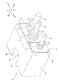
図1及び図2に示すように、モータ制御装置1は、装置本体2と、コネクタケース4とを備える。装置本体2は、その外郭を構成する略直方体状の筺体21を有する。筺体21は、前壁部21a、後壁部21b(図4等を参照)、左壁部21c、右壁部21d(図4等を参照)、上壁部21e、及び、下壁部21f(図4等を参照)を備える。以下では、モータ制御装置1において、左右方向を「幅方向」、上下方向を「高さ方向」、前後方向を「奥行き方向」ともいう。なお、筺体21の形状は、略直方体状に限定されるものではなく、他の形状であってもよい。
図2に示すように、筐体21の前壁部21aの幅方向中央部近傍には、モータの制御に関わる配線が接続される複数のコネクタ12,13,14,15が配置される。コネクタ12,13(以下、「第1コネクタ12,13」ともいう)には、図示しないモータに電力を供給するためのモータパワー線が接続される。コネクタ14(以下、「第2コネクタ14」ともいう)には、図示しないモータのブレーキに信号を出力するためのブレーキ線が接続される。コネクタ15(以下、「第3コネクタ15」ともいう)には、図示しないエンコーダとの間で信号の入出力を行うためのエンコーダ通信線が接続される。
筺体21の前壁部21aの幅方向中央部近傍には、通気口5が設けられている。この例では、通気口5は略T字形状であり、その一部が第1コネクタ12,13よりも上方に配置され、その一部が第1コネクタ12,13の間に配置されている。
コネクタケース4は、装置本体2の筐体21よりも小さく形成された金属製の略直方体状の箱体で、前壁部41a、後壁部41b(図8参照)、左壁部41c、右壁部41d(図8参照)、上壁部41e、及び、図示しない下壁部41fを備える。コネクタケース4は、筐体21のコネクタが配置された壁部、この例では前壁部21aに固定され、通気口5を露出させつつコネクタ12,13,14,15を覆う。コネクタケース4の壁部、この例では前壁部41aには、コネクタケース4と外部機器とを接続するケーブル81,82,83の端部を保持するケーブル保持部材7が設けられている。ケーブル保持部材7の詳細については後述する。
<2.モータ制御装置の回路構成>
まず、図3を用いて、モータ制御装置の回路構成の一例について説明する。
まず、図3を用いて、モータ制御装置の回路構成の一例について説明する。
図3に示すように、モータ制御装置1は、外部電源から入力される電力を所定の電力に変換して負荷に出力する一種の電力変換装置である。具体的には、モータ制御装置1は、3相交流電源100から入力される交流電力を別の交流電力に変換し、例えば8つの3相交流モータM1,M2,M3,M4,M5,M6,M7,M8(以下「モータM」と総称する。)に出力して、動作を制御する。つまり、モータ制御装置1は、8軸制御可能なモータ制御装置である。したがって、モータ制御装置1により例えば6軸ロボットを制御する場合、制御可能な8軸のうちの6軸でロボットを制御し、残りの2軸で例えばロボットの走行や作業対象のワークの回転等を行うロボットの付属機器を制御することが可能である。
なお、モータ制御装置1の制御可能な軸数、つまりモータMの数は、8つに限定されるものではなく、他の数であってもよい。また、外部電源は、3相交流電源に限定されるものではなく、他の電源であってもよい。また、負荷は、3相交流モータに限定されるものではなく、他の負荷であってもよい。
モータ制御装置1は、ダイオードモジュールDM、例えば4つのコンデンサC1,C2,C3,C4(以下「コンデンサC」と総称する。)、例えば8つのパワーモジュールPM1,PM2,PM3,PM4,PM5,PM6,PM7,PM8(以下「パワーモジュールPM」と総称する。)、抵抗器の一例である回生抵抗R、及びスイッチQを含む、複数の電子部品を有する。
ダイオードモジュールDMは、ダイオードを備え、交流電源100から入力される3相交流電力を整流し、直流バスP、Nに直流電力を出力する。コンデンサC1~C4は、直流バスP,Nに渡って接続され、ダイオードモジュールDMが整流した直流電圧を平滑する。パワーモジュールPM1~PM8は、例えばIGBT等の半導体素子で構成される複数のスイッチング素子SW(図3中では1つのみ図示)を備える。そして、パワーモジュールPM1~PM8は、それぞれ、直流電力を所定の3相交流電力に変換し、3相交流モータM1~M8に出力する。上記ダイオードモジュールDMのダイオード、コンデンサC1~C4、及びパワーモジュールPM1~PM8のスイッチング素子SW等は、電力変換回路40を構成する。
また、直流バスP,N間には、上記回生抵抗R及びスイッチQの直列回路が接続されている。スイッチQは、例えばMOSFET等の半導体素子を備え、例えばモータMの急減速時や急停止時等にオンされることで、モータMから直流バスP,Nに入力される回生電力が回生抵抗Rにより消費されるようにする。回生抵抗Rは、スイッチQがオンされた場合に回生電力を消費する。
なお、上記で説明したモータ制御装置1の回路構成は、あくまで一例であり、上記以外の回路構成であってもよい。例えば、抵抗器は、回生抵抗Rに限定されるものではなく、ダイナミックブレーキ等の他の抵抗器であってもよい。また、パワーモジュールPMの数は、8つに限定されるものではなく、他の数であってもよい。また、1つのコンデンサCに2つのパワーモジュールPMが並列に接続される場合に限定されるものではなく、1つのコンデンサCに1つのパワーモジュールPMが接続されたり3つ以上のパワーモジュールPMが並列に接続されてもよい。また、コンデンサCの数は、4つに限定されるものではなく、他の数であってもよい。また、コンデンサCに代えてリアクトルを設置してもよい。
<3.装置本体の内部構造>
次に、図4、図5、及び図6を参照しつつ、モータ制御装置1の装置本体2の内部構造の一例について説明する。なお、装置本体2の筺体21は、図4中では、上壁部21e及び前壁部21aの図示を省略し、図5中では、上壁部21eの図示を省略し、図6中では、前壁部21aの図示を省略している。また、図4~図6中では、装置本体2の要部以外の構成の図示を適宜省略している。
次に、図4、図5、及び図6を参照しつつ、モータ制御装置1の装置本体2の内部構造の一例について説明する。なお、装置本体2の筺体21は、図4中では、上壁部21e及び前壁部21aの図示を省略し、図5中では、上壁部21eの図示を省略し、図6中では、前壁部21aの図示を省略している。また、図4~図6中では、装置本体2の要部以外の構成の図示を適宜省略している。
図4~図6に示すように、装置本体2の筺体21には、第1基板30と、2つの第2基板32,34と、第3基板36と、上記コンデンサC1~C4、パワーモジュールPM1~PM8、及び回生抵抗R等を含む複数の電子部品と、3つのヒートシンク50,52,54と、ファン60等が収納されている。また、筺体21には、2つの通気口、すなわち吸気用の上記通気口5と、排気用の通気口6とが形成されている(図5参照)。また、筺体21には、上記第1コネクタ12,13、第2コネクタ14、及び、第3コネクタ15が配置されている。なお、図4~図6では、煩雑防止のため、コネクタ12~15について簡略化して図示している。
(3-1.基板)
図6に示すように、第1基板30は、その一方側の面が、部品が配置される部品面30a、その他方側の面が、半田付けが行われる半田面30bである。第1基板30は、略長方形状を備え、その板面方向の寸法が、筺体21の下壁部21fの内寸法とほぼ等しい。そして、第1基板30は、部品面30aが上面、半田面30bが下面となるように、筺体21内の下部において下壁部21fに固定されている。
図6に示すように、第1基板30は、その一方側の面が、部品が配置される部品面30a、その他方側の面が、半田付けが行われる半田面30bである。第1基板30は、略長方形状を備え、その板面方向の寸法が、筺体21の下壁部21fの内寸法とほぼ等しい。そして、第1基板30は、部品面30aが上面、半田面30bが下面となるように、筺体21内の下部において下壁部21fに固定されている。
第2基板32,34は、第1基板30の部品面30aに図示しないコネクタ等を介して互いに対向するように立設されている。具体的には、第2基板32,34は、略長方形状を備え、各々の長手方向の寸法が筺体21の奥行き方向の内寸法とほぼ等しく、各々の短手方向の寸法が筺体21の高さ方向の内寸法よりも少し小さい。そして、第2基板32,34は、各々の長手方向が奥行き方向、各々の短手方向が高さ方向に沿いつつ、幅方向に所定の空隙を空けて離間するように、第1基板30の幅方向中央部近傍において平行に対向配置されている。つまり、第2基板32,34は、第2基板32の右面32aと第2基板34の左面34aとが幅方向に対向配置されている。なお、以下では、右面32aを「対向面32a」、左面34aを「対向面34a」ともいう。
第3基板36は、第1基板30の部品面30aに図示しないコネクタ等を介して立設されている。具体的には、第3基板36は、略長方形状を備え、その長手方向の寸法が筺体21の奥行き方向の内寸法とほぼ等しく、その短手方向の寸法が筺体21の高さ方向の内寸法よりも少し小さい。そして、第3基板36は、長手方向が奥行き方向、短手方向が高さ方向に沿いつつ、第2基板32と幅方向に所定の空隙を空けて左方に離間するように、第2基板32と略平行に対向配置されている。第3基板36は、第2基板32と対向する右面36aを有する。
なお、第1基板30、第2基板32,34、及び第3基板36の形状や寸法は、上記に限定されるものではない。また、各基板は単一の基板である必要はなく、複数の基板で構成されてもよい。また、第1基板30は、片面基板である場合に限定されるものではなく、両面に部品が配置される両面基板や、複数の基板が積層された多層基板等であってもよい。また、第3基板36の位置は、第2基板32の左方に限定されるものではなく、右方に位置する第2基板34の右方であってもよい。
(3-2.通気口、ファン)
図5に示すように、通気口5は、幅方向において第2基板32,34間に配置されるように、前壁部21aの幅方向中央部近傍に形成されている。通気口6は、幅方向において第2基板32,34間に配置されるように、後壁部21bの幅方向中央部近傍に形成されている。つまり、通気口5,6は、奥行き方向に対向配置されており、筐体21内の後述する風洞70(図6参照)に連通している。
図5に示すように、通気口5は、幅方向において第2基板32,34間に配置されるように、前壁部21aの幅方向中央部近傍に形成されている。通気口6は、幅方向において第2基板32,34間に配置されるように、後壁部21bの幅方向中央部近傍に形成されている。つまり、通気口5,6は、奥行き方向に対向配置されており、筐体21内の後述する風洞70(図6参照)に連通している。
図2に示すように、通気口5は、前壁部21aに配置された第1コネクタ12,13及び第2コネクタ14等との干渉を回避するように、前壁部21aの幅方向略中央部の略上半部に略T字形状に形成されている。通気口5は、適宜の形状(例えば円形、六角形等)である多数の通気穴5aを備えたハニカム状に形成されている。通気口5の上部は、前壁部21aの上端に近接し、通気口5の下端は、前壁部21aの高さ方向略中央部に位置している。一方、図示は省略するが、通気口6は略四角形状又は略円形状に形成されている。通気口6も、通気口5と同様にハニカム状に形成されている。
なお、通気口5,6の形状は上記に限定されるものではなく、例えば四角形状、円形状、三角形状等、T字状以外の種々の形状とすることができる。また、通気口5,6を各々複数形成してもよい。また、前壁部21aや後壁部21b以外の他の壁部に通気口5,6が形成されてもよい。
ファン60は、第2基板32,34間の通気口6の内側に配置され、上記パワーモジュールPM1~PM8、コンデンサC1~C4、及び回生抵抗Rを冷却するための冷却流路75(図6の二点鎖線参照)を含む風洞70(図6の一点鎖線参照)に送風する。風洞70及びその内部の冷却流路75は、奥行き方向に延びるように形成されている(詳細は後述)。
具体的には、ファン60は、排気ファンであり、通気口5を吸気口、通気口6を排気口として、通気口5から風洞70内(筺体21内)に吸気された空気を通気口6から風洞70外(筺体21外)に排気する。したがって、ファン60が風洞70に送風すると、風洞70内では、主に通気口5から通気口6に向けて空気が流れる。
なお、ファン60は、排気ファンに限定されるものではなく、吸気ファンであってもよい。また、ファン60は、通気口6の内側に設置される場合に限定されるものではなく、通気口5の内側に設置されてもよいし、通気口の外側に設置されてもよい。また、ファンの数は1つに限定されるものではなく、2つ以上であってもよい。また、例えば電子部品の発熱量があまり大きくない等により、ファンを用いた強制冷却を行わなくてもよい場合には、ファンを設置しなくてもよい。
(3-3.ヒートシンク、風洞)
ヒートシンク50,52は、上記パワーモジュールPM1~PM8を冷却するヒートシンクであり、第2基板32,34の対向面32a,34aに沿って配置されている。具体的には、ヒートシンク50は、第2基板32の対向面32aに沿って配置され、上記パワーモジュールPM1~PM4が設置されるヒートシンクベース501と、複数のフィン502とを有する。また、ヒートシンク52は、第2基板34の対向面34aに沿って配置され、上記パワーモジュールPM5~PM8が設置されるヒートシンクベース521と、複数のフィン522とを有する。
ヒートシンク50,52は、上記パワーモジュールPM1~PM8を冷却するヒートシンクであり、第2基板32,34の対向面32a,34aに沿って配置されている。具体的には、ヒートシンク50は、第2基板32の対向面32aに沿って配置され、上記パワーモジュールPM1~PM4が設置されるヒートシンクベース501と、複数のフィン502とを有する。また、ヒートシンク52は、第2基板34の対向面34aに沿って配置され、上記パワーモジュールPM5~PM8が設置されるヒートシンクベース521と、複数のフィン522とを有する。
ヒートシンクベース501は、例えばその四隅に配置されるスペーサSP1を介して第2基板32に固定されている。また、ヒートシンクベース521は、例えばその四隅に配置されるスペーサSP2を介して第2基板34に固定されている。ヒートシンクベース501,521は、高さ方向において各々の上端位置が第2基板32,34の上端位置とほぼ一致するように、配置されている。
なお、ヒートシンクベース501,521は、第2基板32,34に固定される場合に限定されるものではなく、他の部材に固定されてもよい。例えば、ヒートシンクベース501,521が第1基板30に固定され、それらヒートシンクベース501,521に第2基板32,34が固定されてもよい。
複数のフィン502は、ヒートシンクベース501から幅方向に沿って、つまり右方に向けて突出している。また、複数のフィン522は、ヒートシンクベース521から幅方向に沿って、つまり左方に向けて突出している。つまり、フィン502,522は、ヒートシンクベース501,521から互いに近づく方向に突出している。
一方、ヒートシンク54は、上記回生抵抗Rを冷却するヒートシンクである。ヒートシンク54は、第2基板32,34の上方に配置され、上記回生抵抗Rが設置されるヒートシンクベース541と、複数のフィン542とを有する。
ヒートシンクベース541は、略長方形状を備え、その長手方向の寸法が上記ヒートシンクベース501,521の奥行き方向の寸法よりも少し小さく、その短手方向の寸法が第2基板32,34の配置間隔よりも大きい。そして、ヒートシンクベース541は、その長手方向が奥行き方向、その短手方向が幅方向に沿うように、第2基板32,34の上方に第1基板30と平行に配置され、支持部材(図示せず)を介して筐体21に固定されている。つまり、ヒートシンクベース541は、第1基板30と高さ方向に対向配置されている。
なお、ヒートシンクベース541は、筐体21に固定される場合に限定されるものではなく、他の部材に固定されてもよい。また、ヒートシンクベース541は、必ずしも第1基板30と平行に配置されなくてもよい。また、ヒートシンクベース541の形状及び寸法は、上記形状及び寸法に限定されるものではない。
複数のフィン542は、上記フィン502,522間でヒートシンクベース541から第1基板30に向けて、つまり下方に向けて突出している。具体的には、フィン542は、ヒートシンクベース541から、第1基板30の部品面30aに設置されたコンデンサC1~C4の上端部近傍まで突出している。
風洞70は、筐体21内の、第1基板30と第2基板32,34とで囲まれ、且つ第1基板30の部品面30aとヒートシンクベース541との間の空間(図6中の一点鎖線で囲まれた空間)として形成されている。上記ファン60は、この風洞70に送風している。
(3-4.電子部品、冷却流路)
上記パワーモジュールPM1~PM8は、第2基板32,34の対向面32a,34aに配置され、ヒートシンクベース501,521の各々に設置されている。つまり、上記コンデンサC1~C4の各々に接続されるパワーモジュールPM1~PM4と、上記コンデンサC1~C4の各々に接続されるパワーモジュールPM5~PM8とが、第2基板32,34の対向面32a,34aにおいて幅方向に対向配置されている。
上記パワーモジュールPM1~PM8は、第2基板32,34の対向面32a,34aに配置され、ヒートシンクベース501,521の各々に設置されている。つまり、上記コンデンサC1~C4の各々に接続されるパワーモジュールPM1~PM4と、上記コンデンサC1~C4の各々に接続されるパワーモジュールPM5~PM8とが、第2基板32,34の対向面32a,34aにおいて幅方向に対向配置されている。
具体的には、パワーモジュールPM1~PM4は、第2基板32の対向面32aに、第1基板30の板面方向に沿って、つまり奥行き方向に沿って並べて配置され、ヒートシンクベース501の左面501aに設置されている。そして、パワーモジュールPM1~PM4は、各々の例えばピン状の端子tが第2基板32に取り付けられることで、第2基板32に機械的及び電気的に接続される(図6参照)。また、パワーモジュールPM5~PM8は、第2基板34の対向面34aに、第1基板30の板面方向に沿って、つまり奥行き方向に沿って並べて配置され、ヒートシンクベース521の右面521aに設置されている。そして、パワーモジュールPM5~PM8は、各々の例えばピン状の端子tが第2基板34に取り付けられることで、第2基板34に機械的及び電気的に接続される(図6参照)。
また、上記コンデンサC1~C4は、第2基板32,34間で、第1基板30の部品面30aに奥行き方向に沿って並べて配置されている。具体的には、コンデンサC1~C4は、例えば略円柱形状を備え、ヒートシンクベース501,521間で、第1基板30からヒートシンク54に向けて、つまり上方に向けて突出するように、第1基板30の部品面30aに設置されている。
図5に示すように、コンデンサC1~C4は、幅方向に対向配置された、当該コンデンサCに接続される2つのパワーモジュールPMの間に配置されている。つまり、コンデンサC1は、パワーモジュールPM1,PM5の間に配置されている。また、コンデンサC2は、パワーモジュールPM2,PM6の間に配置されている。また、コンデンサC3は、パワーモジュールPM3,PM7の間に配置されている。また、コンデンサC4は、パワーモジュールPM4,PM8の間に配置されている。なお、コンデンサC1~C4の数や配置、形状等は、上記に限定されるものではない。
また、上記回生抵抗Rは、例えば板状に形成されており、第1基板30の部品面30aと対向するように、第2基板32,34の各々の上方に配置される。回生抵抗Rは、その主たる放熱面Raがヒートシンクベース541の上面541aに接触しつつ設置されている。なお、回生抵抗Rの数や配置、形状等は、上記に限定されるものではない。
図6に示すように、本実施形態では、筐体21内のフィン502,522,542が配置された空間を含む、ヒートシンクベース501,521,541とコンデンサC1~C4の上端部で囲まれた空間(図6の二点鎖線で囲まれた空間)が、上記冷却流路75を形成している。
(3-5.コネクタ)
第1コネクタ12,13は、この例ではパワーモジュールPM1~PM8で変換された3相交流電力をモータM1~M8へ出力するためのモータパワー用コネクタであり、例えば高さ方向に長い直方体形状に形成されている。第1コネクタ12は、第2基板32の前端部の右面32a(対向面32a)の下部に固定され、一部が筐体21の前壁部21aから前方に露出している。第1コネクタ12は、第2基板32に設けられた図示しない電気回路を介してパワーモジュールPM1~PM4と接続されている。第1コネクタ13は、第2基板34の前端部の右面34c(対向面34aとは反対側の面)の下部に固定され、一部が筐体21の前壁部21aから前方に露出されている。第1コネクタ13は、第2基板34に設けられた図示しない電気回路を介してパワーモジュールPM5~PM8と接続されている。
第1コネクタ12,13は、この例ではパワーモジュールPM1~PM8で変換された3相交流電力をモータM1~M8へ出力するためのモータパワー用コネクタであり、例えば高さ方向に長い直方体形状に形成されている。第1コネクタ12は、第2基板32の前端部の右面32a(対向面32a)の下部に固定され、一部が筐体21の前壁部21aから前方に露出している。第1コネクタ12は、第2基板32に設けられた図示しない電気回路を介してパワーモジュールPM1~PM4と接続されている。第1コネクタ13は、第2基板34の前端部の右面34c(対向面34aとは反対側の面)の下部に固定され、一部が筐体21の前壁部21aから前方に露出されている。第1コネクタ13は、第2基板34に設けられた図示しない電気回路を介してパワーモジュールPM5~PM8と接続されている。
第1コネクタ12は、筐体21の前壁部21aにおいて第2基板32の前端部に対応する位置に配置され、第1コネクタ13は、筐体21の前壁部21aにおいて第2基板34の前端部に対応する位置に配置される。第1コネクタ12,13は、前壁部21aの通気口5の下半部を挟んだ左右の位置に並列に配置されている。
第1コネクタ12,13の各々は、複数の端子、この例では12の端子(4軸×3相。すなわち4軸分の端子)を備える。前述のように、例えばモータ制御装置1により6軸ロボットを制御し、残りの2軸でロボットの付属機器を制御する場合、コネクタ12,13の24の端子のうち18の端子(6軸×3相)は、6軸ロボットの6つの関節軸のモータへの電力供給用の端子として使用され、残りの6つの端子(2軸×3相)は、付属機器のモータへの電力供給用の端子として使用される。
第2コネクタ14は、この例ではモータM1~M8のブレーキ用コネクタであり、例えば幅方向に長い直方体形状に形成されている。第2コネクタ14は、第1基板30の部品面30aの前端部に固定され、一部が筐体21の前壁部21aから前方に露出されている。第2コネクタ14は、第1基板30に設けられた図示しない電気回路を介してモータM1~M8用の図示しないブレーキ用電気回路と接続されている。
第2コネクタ14は、前壁部21aの第1コネクタ12,13間の通気口5とは反対側の位置に配置されている。第2コネクタ14の上端部は、第1コネクタ12,13の間に位置し、第2コネクタ14の下端部は、前壁部21aの下端に近接している。第2コネクタ14は、複数の端子、この例では8つのモータの各々が有する電磁ブレーキ用の16の制御用の端子(すなわち8軸分の端子)を備える。
第3コネクタ15は、この例ではモータM1~M8のエンコーダ用コネクタである。第3コネクタ15は、第3基板36の前端部の右面36aの下部に固定され、一部が筐体21の前壁部21aから前方に露出されている。第3コネクタ15は、第3基板36に設けられた図示しない電気回路を介してモータM1~M8用の図示しないエンコーダ用電気回路と接続されている。
第3コネクタ15は、前壁部21aにおける2つの第1コネクタ12,13の外側、この例ではコネクタ12の左側の位置に配置される。第3コネクタ15は、この例ではモータM1~M8の各々が有するエンコーダとの通信用の16の端子(すなわち8軸分の端子。図示省略)を備える。
なお、上記コネクタ12,13,14,15は、対応する基板32,34,30,36に対して例えばピン状の端子(図示省略)が取り付けられることで、各基板に電気的に接続されると共に、各基板の前端部に直接的に固定される。なお、ピン状の端子の代わりに、比較的短い配線を用いて接続されてもよい。
また、以上のコネクタ12~15の配置や数は一例であり、図2等に示す配置態様に限定されるものではない。
<4.コネクタケースの構造>
上記図1及び図2に加え、さらに図7及び図8を用いて、コネクタケースの構造の一例について説明する。
上記図1及び図2に加え、さらに図7及び図8を用いて、コネクタケースの構造の一例について説明する。
(4-1.コネクタケースの形状)
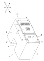
図7に示すように、コネクタケース4は略直方体形状の箱体であり、前述のように、前壁部41a、後壁部41b、左壁部41c、右壁部41d、上壁部41e、及び、図示しない下壁部41fを備える。なお、コネクタケース4の形状は、略直方体形状に限定されるものではなく、他の形状としてもよい。
図7に示すように、コネクタケース4は略直方体形状の箱体であり、前述のように、前壁部41a、後壁部41b、左壁部41c、右壁部41d、上壁部41e、及び、図示しない下壁部41fを備える。なお、コネクタケース4の形状は、略直方体形状に限定されるものではなく、他の形状としてもよい。
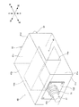
図8に示すように、コネクタケース4の後壁部41b(第1壁部の一例に相当)には、第1コネクタ12,13に対応する位置に開口44,45が、第2コネクタ14に対応する位置に開口46が、第3コネクタ15に対応する位置に開口47がそれぞれ形成されている。コネクタ12,13,14,15の前壁部21aから前方に露出した部分は、これら開口44,45,46,47を介してコネクタケース4内に収容される。コネクタケース4の後壁部41bと残りの壁部(第2壁部の一例に相当)である前壁部41a、左壁部41c、右壁部41d、上壁部41e、下壁部41fとが、コネクタ12,13,14,15を収容する閉空間を形成する。
コネクタケース4の後壁部41bには、複数のねじ孔49が形成されている。一方、装置本体2の筐体21の前壁部21aにおける上記ねじ孔49に対応する位置には、複数の貫通孔51が形成されている。コネクタケース4は、上記貫通孔51に挿通された図示しない固定ねじが上記ねじ孔49に締結されることで前壁部21aに固定され、固定ねじを緩めることで前壁部21aから取り外される。これにより、コネクタケース4は前壁部21aに着脱可能である。コネクタケース4が前壁部21aに固定された際には、コネクタケース4の後部壁41bと筐体21の前壁部21aとは、その間にほぼ隙間がないように接触(密着)する。なお、ねじ以外の固定手段を用いてコネクタケース4を固定してもよい。
コネクタケース4は、筐体21の通気口5を流れる空気の流路を形成する形状を有している。具体的には、コネクタケース4の筐体21側端部の幅方向略中央部に、通気口5の形状に応じた凹部42が上壁部41eと後壁部41bとに亘って形成されている。図7及び図8に示すように、凹部42は、幅方向に間隔を空けて対向配置された略矩形状の右面部42a及び左面部42bと、右面部42a及び左面部42bの前端の間を繋ぐ略矩形状の前面部42cと、右面部42a、左面部42b及び前面部42cの下端の間を繋ぐ略矩形状の下面部42dとを備える。右面部42aと左面部42bとの間隔は、通気口5の第1コネクタ12,13間に配置される部分の幅方向寸法と略一致している。
図1に示すように、コネクタケース4が筐体21の前壁部21aに固定された際に、凹部42が前壁部21aの通気口5に相対し、略直方体形状の空気流路を形成する。なお、凹部42の上記形状は一例であり、通気口5の形状に応じた種々の形状に形成することができる。
なお、コネクタケース4の高さ方向の寸法は筐体21の高さ方向寸法より小さく設定されており、コネクタケース4の上壁部41eと筐体21の上壁部21eとの間には隙間が形成される。通気口5の一部は、前壁部21aの上記隙間部分に配置されることで、上記凹部42とあわせて、通気口5を流れる空気の流路を確保できる構造となっている。
(4-2.コネクタケースのケーブル保持構造)
次に、コネクタケース4によるケーブルの保持構造の一例ついて説明する。図7に示すように、コネクタケース4の前壁部41aには、コネクタケース4とモータ制御装置1の制御対象である外部機器とを接続するケーブル81,82,83の端部を保持するケーブル保持部材7が設けられている。本実施形態では、ケーブル保持部材7として、例えばケーブルグランド76,77,78が使用される。
次に、コネクタケース4によるケーブルの保持構造の一例ついて説明する。図7に示すように、コネクタケース4の前壁部41aには、コネクタケース4とモータ制御装置1の制御対象である外部機器とを接続するケーブル81,82,83の端部を保持するケーブル保持部材7が設けられている。本実施形態では、ケーブル保持部材7として、例えばケーブルグランド76,77,78が使用される。
ケーブル81は、コネクタケース4と主たる制御対象である外部機器(例えばロボット等。中継ボックス等でもよい)とを接続するケーブルであり、ケーブル81内には外部機器の軸数に応じたモータパワー線及びブレーキ線が配線される。ケーブル82は、コネクタケース4と他の制御対象である外部機器(例えばロボットの付属機器等。中継ボックス等でもよい)とを接続するケーブルであり、ケーブル82内には外部機器の軸数に応じたモータパワー線及びブレーキ線が配線される。ケーブル83は、コネクタケース4とエンコーダ(中継ボックス等でもよい)とを接続するケーブルであり、ケーブル83内には通信するエンコーダの数に応じたエンコーダ通信線が配線される。
図7に示すように、コネクタケース4の前壁部41aには、複数(この例では2つ)のパネル72,73(板部材の一例に相当)が取り付けられている。これらパネル72,73は、例えば金属製の四角形状の板部材である。なお、パネルの数、材質、形状等は上記に限定されるものではない。各パネル72,73の例えば四隅には、複数の貫通孔74(図1では図示省略)が形成されている。一方、コネクタケース4の前壁部41aにおける上記貫通孔74に対応する位置には、図示しないねじ孔が形成されている。パネル72,73は、上記貫通孔74に挿通された図示しない固定ねじが上記ねじ孔に締結されることでコネクタケース4の前壁部41aに固定され、固定ねじを緩めることで前壁部41aから取り外される。これにより、パネル72,73はコネクタケース4に着脱可能である。なお、ねじ以外の固定手段を用いてパネル72,73を固定してもよい。
ケーブルグランド76は、ケーブル81の端部81aに取り付けられ、パネル72に固定される。これにより、ケーブル81の端部81aがケーブルグランド76及びパネル72を介してコネクタケース4に保持される。ケーブルグランド77は、ケーブル82の端部82aに取り付けられ、パネル72に固定される。これにより、ケーブル82の端部82aがケーブルグランド77及びパネル72を介してコネクタケース4に保持される。ケーブルグランド78は、ケーブル83の端部83aに取り付けられ、パネル73に固定される。これにより、ケーブル83の端部83aがパネル73を介してコネクタケース4に保持される。
なお、上記ではパネル72に2つのケーブルグランド76,77を固定したが、これに限定されるものではない。例えば、1つのパネルに1つのケーブルグランドを固定してもよいし、1つのパネルに3つのケーブルグランド76,77,78を固定してもよい。なお、本実施形態では、同種類のケーブル81,82(モータパワー線とブレーキ線が配線されるケーブル)に対応するケーブルグランド76,77を1つのパネル72にまとめ、異なる種類のケーブル83に対応するケーブルグランド78については別のパネル73に分けることで、ケーブルグランドを種別ごとに区分けすることが可能となり、管理が容易となる。
(4-3.コネクタケース内の配線)
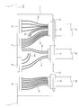
次に、図9を用いてコネクタケース内における配線の一例について説明する。なお、図9では、煩雑防止のため、各コネクタ12,13,14,15に接続される配線の本数を、軸数に対応する本数として図示している。例えば第1コネクタ12,13には各々12本(4軸×3相)のモータパワー線が接続されるが、ここでは各々4本のモータパワー線Cmとして図示している。同様に第2コネクタ14には16本(8軸分)のブレーキ線が接続されるが、ここでは8本のブレーキ線Cbとして図示している。第3コネクタ15には、8本(8軸分)のエンコーダ通信線Ceが接続されている。
次に、図9を用いてコネクタケース内における配線の一例について説明する。なお、図9では、煩雑防止のため、各コネクタ12,13,14,15に接続される配線の本数を、軸数に対応する本数として図示している。例えば第1コネクタ12,13には各々12本(4軸×3相)のモータパワー線が接続されるが、ここでは各々4本のモータパワー線Cmとして図示している。同様に第2コネクタ14には16本(8軸分)のブレーキ線が接続されるが、ここでは8本のブレーキ線Cbとして図示している。第3コネクタ15には、8本(8軸分)のエンコーダ通信線Ceが接続されている。
図9に示す例は、前述のように、例えばモータ制御装置1により6軸ロボットを制御し、残りの2軸でロボットの付属機器を制御する場合の配線の一例であり、ケーブル81は6軸のロボットへ接続されるケーブル、ケーブル82は2軸の付属機器に接続されるケーブル、ケーブル83は8軸分のエンコーダケーブルである。図9に示すように、コネクタケース4の内部では、第1コネクタ12,13に接続された計8本のモータパワー線Cm、第2コネクタ14に接続された8本のブレーキ線Cb、及び、第3コネクタ15に接続された8本のエンコーダ通信線Ceが、ケーブルグランド76に保持されたケーブル81、ケーブルグランド77に保持されたケーブル82、ケーブルグランド78に保持されたケーブル83のケーブル系統ごとに区分けして配線されている。
具体的には、第1コネクタ13の4本のモータパワー線Cmに、第1コネクタ12の4本のモータパワー線Cmのうちの2本が加えられて、6本(6軸分)のモータパワー線Cmとしてケーブル81内に配線される。また、第2コネクタ14の8本のブレーキ線Cbのうちの6本がケーブル81内に配線される。これにより、ケーブル81内には6軸分のモータパワー線Cm及びブレーキ線Cbがそれぞれ配線される。
また、第1コネクタ12の4本のモータパワー線Cmのうちの残りの2本がケーブル82内に配線され、第2コネクタ14の8本のブレーキ線Cbのうちの残りの2本がケーブル82内に配線される。これにより、ケーブル82内には2軸分のモータパワー線Cm及びブレーキ線Cbがそれぞれ配線される。
また、第3コネクタ15の8本のエンコーダ通信線Ceは、8軸分のエンコーダ通信線Ceとしてそのままケーブル83内に配線される。
なお、以上のコネクタケース4内における配線の区分けは一例であり、これに限定されるものではない。例えば、ケーブル81とケーブル82により6軸と2軸以外(例えば7軸と1軸、5軸と3軸等)に軸数を区分けしたり、付属の機器が無い場合にはケーブル82を不要としたり、エンコーダ通信線を区分けする場合にはケーブル83を複数とする等、制御対象である外部機器の仕様や構成等に応じてコネクタケース4内での配線の区分けを柔軟に変更することが可能である。その際には、プレート72,73を所望のケーブル構成に対応したプレートに変更することで、コネクタケース4に取り付けられるケーブルグランドを変更し、コネクタケース4と外部機器とのケーブル接続構成を容易に変更することが可能である。
以上において、モータパワー線Cm、ブレーキ線Cb、及びエンコーダ通信線Ceが、モータの制御に関わる配線の一例に相当する。また、コネクタケース4がケーブルごとに区分けする手段の一例に相当する。
<5.実施形態の効果>
以上説明したように、本実施形態のモータ制御装置1は、複数の壁部21a~21fを備えた筐体21と、筐体21の前壁部21aに配置され、モータMの制御に関わる配線Cm,Cb,Ceが接続されるコネクタ12,13,14,15と、コネクタ12,13,14,15が配置された前壁部21aに固定され、コネクタ12,13,14,15を覆うコネクタケース4と、コネクタケース4に固定され、コネクタケース4と外部機器とを接続するケーブル81,82,83の端部81a,82a,83aを保持するケーブル保持部材7としてのケーブルグランド76,77,78と、を有する。
以上説明したように、本実施形態のモータ制御装置1は、複数の壁部21a~21fを備えた筐体21と、筐体21の前壁部21aに配置され、モータMの制御に関わる配線Cm,Cb,Ceが接続されるコネクタ12,13,14,15と、コネクタ12,13,14,15が配置された前壁部21aに固定され、コネクタ12,13,14,15を覆うコネクタケース4と、コネクタケース4に固定され、コネクタケース4と外部機器とを接続するケーブル81,82,83の端部81a,82a,83aを保持するケーブル保持部材7としてのケーブルグランド76,77,78と、を有する。
これにより、コネクタ12,13,14,15に接続された複数の配線Cm,Cb,Ceを、コネクタケース4の内部で系統ごと(ケーブル保持部材7により保持されたケーブル81,82,83ごと)に区分けして配線することができる。そして、コネクタケース4内の配線態様は自由に変更できるので、外部装置の仕様や構成等に応じて多様なケーブル接続構成に柔軟に対応することができる。
また、コネクタケース4が筐体21に一体的に設けられるので、ケーブル接続構成を変更するための中継ボックス等が不要となり、システム構成をコンパクト化できる。さらに、コネクタケース4を設けることで、コネクタ12,13,14,15と配線Cm,Cb,Ceとの接続部分を物理的に保護できると共に、コネクタ配置部分を介して筐体21の内外に流出入するノイズ(例えばパワーモジュールPMのスイッチング素子SWで発生し筐体21の外部に漏れ出すノイズや、外部機器から筐体21内に侵入するノイズ等)の影響を低減できる。
また、本実施形態では特に、コネクタケース4が筐体21の前壁部21aに着脱可能である。これにより、コネクタ12~15に対する配線Cm,Cb,Ceの接続作業等についてコネクタケース4を筐体21から取り外して行うことができるので、作業性を向上できる。また、例えばモータ制御装置1の持ち運びや保管の際等には、コネクタケース4を筐体21から取り外して小型化できるので、利便性を向上できる。
また、本実施形態では特に、筐体21のコネクタケース4が固定された前壁部21aに通気口5が形成されており、コネクタケース4は、通気口5を流れる空気の流路を形成する形状を有する。これにより、コネクタケース4が筐体21の通気口5を閉塞するのを防止でき、筐体21内に空気を円滑に流すことができる。したがって、モータ制御装置1の冷却性能を確保しつつ、筐体21にコネクタケース4を設置することができる。
また、本実施形態では特に、コネクタケース4には、筐体21側の端部に通気口5の形状に応じた凹部42が形成されているので、次の効果を奏する。すなわち、コネクタケース4の筐体21側の端部に凹部42を形成するので、コネクタケース4の筐体21とは反対側の端部である前壁部41aにケーブル保持部材7(ケーブルグランド76,77,78)を集中して配置できる。これにより、ケーブルの引き回しやケーブル保持部材7の交換等の作業性を向上できる。
また、本実施形態では特に、コネクタケース4は、後壁部41bが筐体21の前壁部21aに接触するように固定されている。これにより、次の効果を奏する。すなわち、筐体21の前壁部21aに形成された開口44,45,46,47とコネクタ12,13,14,15との間には、寸法公差等を許容するために隙間が設けられる場合がある。このため、当該隙間を介して筐体21の内部で発生するノイズ(例えばスイッチング素子SWで発生するノイズ)が外部に漏れ出したり、筐体21の外部からのノイズが内部に侵入する可能性がある。
本実施形態では、コネクタケース4の後壁部41bを筐体21の前壁部21aに接触させて固定するので、後壁部41bと前壁部21aとの隙間をなくし、コネクタケース4の内部を略密閉空間とすることができる。その結果、上述の筐体21内部で発生するノイズや外部からのノイズをコネクタケース4により遮蔽することが可能となり、ノイズの影響をさらに低減できる。
また、本実施形態では特に、ケーブル保持部材7(ケーブルグランド76,77,78)は、コネクタケース4の前壁部41aに着脱可能なパネル72,73に固定されている。これにより、パネル72,73を交換することで、ケーブル保持部材7を容易に交換することができる。したがって、外部装置の仕様や構成等に応じてケーブルの種類や本数を容易に変更することができる。
また、本実施形態では特に、コネクタ12が前端部に接続された基板32、コネクタ13が前端部に接続された基板34、コネクタ14が前端部に接続された基板30、コネクタ15が前端部に接続された基板36をさらに有し、コネクタ12,13,14,15は、筐体21の前壁部21aにおいて基板32,34,30,36の前端部に対応する位置に配置される。これにより、各コネクタと対応する基板との距離を短くすることができるので、筐体21の内部において基板32,34,30、36とコネクタ12,13,14,15との間の配線距離を短縮でき、筐体21内の配線を削減できる。特に、各コネクタについてピン端子等を用いて各基板に対して直接的に固定した場合には、配線を引き回す必要が無くなるので、筐体21内の配線をさらに削減できる。
また、本実施形態では特に、第1コネクタ12,13が第2基板32,24の各々の前端部に接続され、筐体21の前壁部21aに並列に配置されており、通気口5が、少なくとも一部が2つの第1コネクタ12,13の間に位置するように前壁部21aに形成されている。これにより、筐体21の内部において、第1基板30と2つの第2基板32,34とで囲まれた風洞70に通気口5を介して空気を流すことができるので、第1基板30や第2基板32,34に配置された発熱する電子部品を同時且つ効率的に冷却することができる。
また、本実施形態では特に、第2コネクタ14が、2つの第1コネクタ12,13に対し通気口5とは反対側の位置に配置されている。これにより、筐体21の前壁部21aにおける2つの第1コネクタ12,13と、第2コネクタ14と、通気口5の位置を、各基板32,34,30と風洞70等の配置構成に応じて最適化することができる。また、2つの第1コネクタ12,13と第2コネクタ14とを近傍する位置に集中的に配置することができるので、コネクタケース4を小型化できる。
また、本実施形態では特に、第3コネクタ15が、第3基板36の前端部に固定され、2つの第1コネクタ12,13の外側に配置されている。これにより、第3基板36を2つの第2基板32,34の外側に配置できるので、第3基板36に配置された電子部品等への熱の影響を低減できる。またこのように、複数の基板30,32,34,36の配置構成を発熱量等に応じて最適化することで、第3基板36への熱の影響を低減しつつ第1基板30及び第2基板32,34の電子部品を効率的に冷却することができる。
<6.変形例>
なお、開示の実施形態は、上記に限られるものではなく、その趣旨及び技術的思想を逸脱しない範囲内で種々の変形が可能である。以下、そのような変形例を説明する。
なお、開示の実施形態は、上記に限られるものではなく、その趣旨及び技術的思想を逸脱しない範囲内で種々の変形が可能である。以下、そのような変形例を説明する。
(6-1.ケーブル保持部材をコネクタとする場合)
上記実施形態では、ケーブル81,82,83の端部81a,82a,83aを保持するケーブル保持部材7をケーブルグランドとしたが、これに限定されるものではなく、コネクタとしてもよい。本変形例の一例を図10に示す。なお、図10において前述の図7と同様の構成には同符号を付し、適宜説明を省略する。
上記実施形態では、ケーブル81,82,83の端部81a,82a,83aを保持するケーブル保持部材7をケーブルグランドとしたが、これに限定されるものではなく、コネクタとしてもよい。本変形例の一例を図10に示す。なお、図10において前述の図7と同様の構成には同符号を付し、適宜説明を省略する。
図10に示すように、本変形例では、ケーブル保持部材7Aとして、例えばコネクタ84,85,86が使用される。コネクタケース4の前壁部41aには、複数(この例では2つ)のパネル72A,73A(板部材の一例に相当)が取り付けられている。パネル72A,73Aは、図示しない固定ねじによりコネクタケース4に着脱可能である。パネル72Aにはコネクタ84,85が固定され、パネル73Aにはコネクタ86が固定されている。
コネクタ84には、前述のケーブル81が図示しないコネクタを介して装着される。これにより、ケーブル81の端部81aがコネクタ84及びパネル72Aを介してコネクタケース4Aに保持される。コネクタ85には、前述のケーブル82が図示しないコネクタを介して装着される。これにより、ケーブル82の端部82aがコネクタ85及びパネル72Aを介してコネクタケース4Aに保持される。コネクタ86には、前述のケーブル83が図示しないコネクタを介して装着される。これにより、ケーブル83の端部83aがコネクタ86及びパネル73Aを介してコネクタケース4Aに保持される。
コネクタ84,85,86の各々の内側には、コネクタケース4内で区分けされた配線がそれぞれ接続される。すなわち、前述の図9に示す例では、コネクタ84の内側には6軸分のモータパワー線Cm及びブレーキ線Cbがそれぞれ接続され、コネクタ85の内側には2軸分のモータパワー線Cm及びブレーキ線Cbがそれぞれ接続され、コネクタ86の内側には8軸分のエンコーダ通信線Ceがそれぞれ接続される。
本変形例によっても、コネクタ12,13,14,15に接続された複数の配線Cm,Cb,Ceを、コネクタケース4の内部で系統ごとに区分けして配線することができる等、上記実施形態と同様の効果を奏する。また、本変形例では、ケーブル保持部材7Aをコネクタ84,85,86で構成しているので、ケーブルの端部に設けられた図示しないコネクタを対応するコネクタ84,85,86に差し込むだけでケーブルの端部をコネクタケース4Aに保持させることができ、ケーブルの端部の保持作業が一層容易になる等の効果もある。
(6-2.コネクタケースの空気流路を貫通穴とする場合)
上記実施形態では、筐体21の前壁部21aの通気口5を流れる空気の流路を形成するために、コネクタケース4の筐体21側の端部に凹部42を形成したが、コネクタケース4の空気流路の形状はこれに限定されるものではない。例えば、コネクタケース4を筒状として貫通穴を設けてもよい。本変形例の一例を図11に示す。なお、図11において前述の図7等と同様の構成には同符号を付し、適宜説明を省略する。
上記実施形態では、筐体21の前壁部21aの通気口5を流れる空気の流路を形成するために、コネクタケース4の筐体21側の端部に凹部42を形成したが、コネクタケース4の空気流路の形状はこれに限定されるものではない。例えば、コネクタケース4を筒状として貫通穴を設けてもよい。本変形例の一例を図11に示す。なお、図11において前述の図7等と同様の構成には同符号を付し、適宜説明を省略する。
図11に示すように、本変形例のコネクタケース4Bでは、左壁部41cにケーブルグランド76によってケーブル81の端部81aが保持され、右壁部41dに図示しないケーブルグランド77,78によってケーブル82,83の端部が保持されている。なお、各ケーブルグランドが固定されたパネル(図11ではパネル72Bのみ図示)がコネクタケース4Bに着脱可能である点は、前述の実施形態と同様である。
また、コネクタケース4Bには、前壁部41aに開口部48aを有し、後壁部41bに開口部48bを有する例えば角筒状の前後方向の貫通穴48が設けられている。なお、貫通穴48の形状は、角筒状以外の形状(例えば円筒状)でもよい。貫通穴48は、コネクタケース4Bの後壁部41bが筐体21の前壁部21aに接触するように取り付けられた際に、開口部48bが前壁部21aの通気口5の全部又は一部を覆うように位置しており、通気口5を流れる空気の流路を形成する。
上記貫通穴48は、筐体21の前壁部21aに配置された各コネクタ12,13,14,15が開口部48b内に位置しないように、言い換えればコネクタ12,13,14,15の全てが貫通穴48の外周側のコネクタケース4B内に収容されるように形成される。なお、上記コネクタの一部(例えば第2コネクタ14)が開口部48b内に位置することにより、貫通穴48を介して外部に露出する場合には、ノイズの漏洩を防止するために、開口46と第2コネクタ14との隙間を適宜の材質のシール材等でシールするのが好ましい。
本変形例によっても、上記実施形態と同様の効果を奏する。
(6-3.凹部の前面部を傾斜させる場合)
以上の実施形態では、コネクタケース4の凹部42を略直方体状に、言い換えれば前面部42cを略上下方向に沿うように形成したが、凹部42の形状はこれに限定されるものではない。例えば、図12に示すように、前面部42cの下端部が上端部よりも後側に位置するように前面部42cを傾斜させた凹部42Cが形成されたコネクタケース4Cとしてもよい。これにより、凹部42C内に流入する空気の抵抗を低減し、ファン60による風量を増加できる効果を得る。
以上の実施形態では、コネクタケース4の凹部42を略直方体状に、言い換えれば前面部42cを略上下方向に沿うように形成したが、凹部42の形状はこれに限定されるものではない。例えば、図12に示すように、前面部42cの下端部が上端部よりも後側に位置するように前面部42cを傾斜させた凹部42Cが形成されたコネクタケース4Cとしてもよい。これにより、凹部42C内に流入する空気の抵抗を低減し、ファン60による風量を増加できる効果を得る。
<7.ロボットシステム>
次に、図13を用いて、上記実施形態に係るモータ制御装置1を用いてロボットを制御するロボットシステムの一例について説明する。
次に、図13を用いて、上記実施形態に係るモータ制御装置1を用いてロボットを制御するロボットシステムの一例について説明する。
図13に示すように、ロボットシステム110は、ロボットコントローラとしてのモータ制御装置1と、モータ制御装置1によって制御されるロボット120とを有する。ロボット120は、アーム130を備える。これらロボット120及びモータ制御装置1は、前述のケーブル81,83を介して相互通信可能に接続されている。なお、モータ制御装置1を、例えばロボット120のアーム130部分に設置する等、ロボット120側に設けてもよい。また、図13では、ロボット120の走行や作業対象のワークの回転等を行う付属機器及びケーブル82の図示を省略している。
ロボット120は、いわゆる6軸ロボットである。具体的には、ロボット120のアーム130は、固定部131と、複数(この例では5個)のリンク部材L1~L5と、これら5個のリンク部材L1~L5のうちアーム130の最も基端側に位置するリンク部材L1と固定部131、及び、これら5個のリンク部材L1~L5のうち隣接するリンク部材同士、を屈折可能に連結する複数(この例では6個)の関節機構S1~S6と、これら6個の関節機構S1~S6にそれぞれ設けられ、駆動対象のリンク部材L1~L5への駆動力を発生するアクチュエータA1~A6と、上記6個の関節機構S1~S6にそれぞれ設けられた図示しない弾性部材とを有している。
アクチュエータA1~A6は、この例では一般産業用機械の動力源として用いられる、いわゆるACサーボモータであり、固定子及び回転子を有し、回転力を出力するモータと、モータの出力(回転速度)を所定の減速比で減速することにより、モータのトルクを増幅する減速機と、回転子を制動するブレーキと、モータの回転軸等の回転体の回転位置を検出するエンコーダとを備えている。
アクチュエータA1~A6に備えられたモータの固定子及び回転子と、固定部131及びリンク部材L1~L6との連結関係は次のとおりである。すなわち、アクチュエータA1に備えられたモータの固定子が固定部131に連結され、当該モータの回転子がリンク部材L1に連結される。アクチュエータA2に備えられたモータのアーム130の基端側に位置する固定子がリンク部材L1に連結され、当該モータのアーム130の先端側に位置する回転子がリンク部材L2に連結される。同様に、アクチュエータA3に備えられたモータのアーム130の基端側に位置する固定子がリンク部材L2に連結され、当該モータのアーム130の先端側に位置する回転子がリンク部材L3に連結される。アクチュエータA4に備えられたモータのアーム130の基端側に位置する固定子がリンク部材L3に連結され、当該モータのアーム130の先端側に位置する回転子がリンク部材L4に連結される。アクチュエータA5に備えられたモータのアーム130の基端側に位置する固定子がリンク部材L4に連結され、当該モータのアーム130の先端側に位置する回転子がリンク部材L5に連結される。アクチュエータA6に備えられたモータのアーム130の基端側に位置する固定子がリンク部材L5に連結され、当該モータのアーム130の先端側に位置する回転子がリンク部材L6に連結される。
モータ制御装置1は、上記アクチュエータA1~A6の6つのモータに対し、ケーブル81内に配線された複数のモータパワー線Cmを介して電力を供給する。また、モータ制御装置1は、上記アクチュエータA1~A6の6つのブレーキに対し、ケーブル81内に配線された複数のブレーキ線Cbを介して信号を出力し、ブレーキのオン・オフを制御する。また、モータ制御装置1は、上記アクチュエータA1~A6の6つのエンコーダに対し、ケーブル83内に配線された複数のエンコーダ通信線Ceを介して通信を行う。
なお、以上では、モータ制御装置1が6軸ロボットを制御する場合を一例として説明したが、ロボット120は、4軸ロボット、7軸ロボット等、6軸以外のロボットであってもよい。
以上の説明において、「垂直」「平行」「平面」等の記載がある場合には、当該記載は厳密な意味ではない。すなわち、それら「垂直」「平行」「平面」とは、設計上、製造上の公差、誤差が許容され、「実質的に垂直」「実質的に平行」「実質的に平面」という意味である。
また、以上の説明において、外観上の寸法や大きさが「同一」「等しい」「異なる」等の記載がある場合は、当該記載は厳密な意味ではない。すなわち、それら「同一」「等しい」「異なる」とは、設計上、製造上の公差、誤差が許容され、「実質的に同一」「実質的に等しい」「実質的に異なる」という意味である。
また、以上既に述べた以外にも、上記実施形態や各変形例による手法を適宜組み合わせて利用しても良い。
その他、一々例示はしないが、上記実施形態や各変形例は、その趣旨を逸脱しない範囲内において、種々の変更が加えられて実施されるものである。
1 モータ制御装置
4 コネクタケース
4A コネクタケース
4B コネクタケース
4C コネクタケース
5 通気口
7 ケーブル保持部材
7A ケーブル保持部材
12 コネクタ、第1コネクタ
13 コネクタ、第1コネクタ
14 コネクタ、第2コネクタ
15 コネクタ、第3コネクタ
21 筐体
21a 前壁部(壁部の一例)
21b 後壁部(壁部の一例)
21c 左壁部(壁部の一例)
21d 右壁部(壁部の一例)
21e 上壁部(壁部の一例)
21f 下壁部(壁部の一例)
30 第1基板(基板の一例)
32 第2基板(基板の一例)
34 第2基板(基板の一例)
36 第3基板(基板の一例)
41a 前壁部(第2壁部の一例)
41b 後壁部(第1壁部の一例)
41c 左壁部(第2壁部の一例)
41d 右壁部(第2壁部の一例)
41e 上壁部(第2壁部の一例)
41f 下壁部(第2壁部の一例)
42 凹部(流路を形成する形状の一例)
42C 凹部(流路を形成する形状の一例)
48 貫通穴(流路を形成する形状の一例)
72 パネル(板部材の一例)
72A パネル(板部材の一例)
72B パネル(板部材の一例)
73 パネル(板部材の一例)
73A パネル(板部材の一例)
76 ケーブルグランド(ケーブル保持部材の一例)
77 ケーブルグランド(ケーブル保持部材の一例)
78 ケーブルグランド(ケーブル保持部材の一例)
81 ケーブル
82 ケーブル
83 ケーブル
84 コネクタ(ケーブル保持部材の一例)
85 コネクタ(ケーブル保持部材の一例)
86 コネクタ(ケーブル保持部材の一例)
110 ロボットシステム
120 ロボット
Cb ブレーキ線(配線の一例)
Ce エンコーダ通信線(配線の一例)
Cm モータパワー線(配線の一例)
M1~M8 モータ
4 コネクタケース
4A コネクタケース
4B コネクタケース
4C コネクタケース
5 通気口
7 ケーブル保持部材
7A ケーブル保持部材
12 コネクタ、第1コネクタ
13 コネクタ、第1コネクタ
14 コネクタ、第2コネクタ
15 コネクタ、第3コネクタ
21 筐体
21a 前壁部(壁部の一例)
21b 後壁部(壁部の一例)
21c 左壁部(壁部の一例)
21d 右壁部(壁部の一例)
21e 上壁部(壁部の一例)
21f 下壁部(壁部の一例)
30 第1基板(基板の一例)
32 第2基板(基板の一例)
34 第2基板(基板の一例)
36 第3基板(基板の一例)
41a 前壁部(第2壁部の一例)
41b 後壁部(第1壁部の一例)
41c 左壁部(第2壁部の一例)
41d 右壁部(第2壁部の一例)
41e 上壁部(第2壁部の一例)
41f 下壁部(第2壁部の一例)
42 凹部(流路を形成する形状の一例)
42C 凹部(流路を形成する形状の一例)
48 貫通穴(流路を形成する形状の一例)
72 パネル(板部材の一例)
72A パネル(板部材の一例)
72B パネル(板部材の一例)
73 パネル(板部材の一例)
73A パネル(板部材の一例)
76 ケーブルグランド(ケーブル保持部材の一例)
77 ケーブルグランド(ケーブル保持部材の一例)
78 ケーブルグランド(ケーブル保持部材の一例)
81 ケーブル
82 ケーブル
83 ケーブル
84 コネクタ(ケーブル保持部材の一例)
85 コネクタ(ケーブル保持部材の一例)
86 コネクタ(ケーブル保持部材の一例)
110 ロボットシステム
120 ロボット
Cb ブレーキ線(配線の一例)
Ce エンコーダ通信線(配線の一例)
Cm モータパワー線(配線の一例)
M1~M8 モータ
Claims (11)
- モータを制御するモータ制御装置であって、
複数の壁部を備えた筐体と、
少なくとも1つの前記壁部に配置され、前記モータの制御に関わる配線が接続されるコネクタと、
前記コネクタが配置された前記壁部に固定され、前記コネクタを覆うコネクタケースと、
前記コネクタケースに固定され、前記コネクタケースと外部機器とを接続するケーブルの端部を保持するケーブル保持部材と、
を有することを特徴とするモータ制御装置。 - 前記コネクタケースは、
前記壁部に着脱可能である
ことを特徴とする請求項1に記載のモータ制御装置。 - 前記筐体は、
前記コネクタケースが固定された前記壁部に通気口が形成されており、
前記コネクタケースは、
前記通気口を流れる空気の流路を形成する形状を有する
ことを特徴とする請求項1又は2に記載のモータ制御装置。 - 前記コネクタケースは、
前記筐体側の端部に前記通気口の形状に応じた凹部が形成されている
ことを特徴とする請求項3に記載のモータ制御装置。 - 前記コネクタケースは、
前記コネクタに対応する位置に開口が形成された第1壁部と、
前記コネクタを収容する閉空間を前記第1壁部と共に形成する複数の第2壁部と、を有し、
前記第1壁部が前記筐体の前記壁部に接触するように固定されている
ことを特徴とする請求項1乃至4のいずれか1項に記載のモータ制御装置。 - 前記ケーブル保持部材は、
前記第2壁部に着脱可能な板部材に固定されている
ことを特徴とする請求項5に記載のモータ制御装置。 - 前記筐体の内部に配置され、前記コネクタが端部に接続された基板をさらに有し、
前記コネクタは、
前記筐体の前記壁部において前記基板の前記端部に対応する位置に配置される
ことを特徴とする請求項1乃至6のいずれか1項に記載のモータ制御装置。 - 前記基板は、
第1基板と、
前記第1基板に互いに対向するように立設された2つの第2基板と、を含み、
前記コネクタは、
前記2つの第2基板の各々の端部に接続され、前記筐体の前記壁部に並列に配置された2つの第1コネクタを含み、
前記筐体は、
前記コネクタケースが固定された前記壁部に、少なくとも一部が前記2つの第1コネクタの間に位置する通気口が形成されている
ことを特徴とする請求項7に記載のモータ制御装置。 - 前記コネクタは、
前記第1基板の端部に接続され、少なくとも一部が前記2つの第1コネクタの間に配置された第2コネクタを含み、
前記第2コネクタは、
前記2つの第1コネクタに対し前記通気口とは反対側の位置に配置されている
ことを特徴とする請求項8に記載のモータ制御装置。 - 前記基板は、
前記2つの第2基板の外側において前記第1基板に立設された第3基板を含み、
前記コネクタは、
前記第3基板の端部に接続され、前記2つの第1コネクタの外側に配置された第3コネクタを含む
ことを特徴とする請求項8又は9に記載のモータ制御装置。 - 請求項1乃至10に記載のモータ制御装置と、
該モータ制御装置によって制御されるロボットと、を有する
ことを特徴とするロボットシステム。
Priority Applications (1)
| Application Number | Priority Date | Filing Date | Title |
|---|---|---|---|
| PCT/JP2014/077974 WO2016063352A1 (ja) | 2014-10-21 | 2014-10-21 | モータ制御装置及びロボットシステム |
Applications Claiming Priority (1)
| Application Number | Priority Date | Filing Date | Title |
|---|---|---|---|
| PCT/JP2014/077974 WO2016063352A1 (ja) | 2014-10-21 | 2014-10-21 | モータ制御装置及びロボットシステム |
Publications (1)
| Publication Number | Publication Date |
|---|---|
| WO2016063352A1 true WO2016063352A1 (ja) | 2016-04-28 |
Family
ID=55760426
Family Applications (1)
| Application Number | Title | Priority Date | Filing Date |
|---|---|---|---|
| PCT/JP2014/077974 Ceased WO2016063352A1 (ja) | 2014-10-21 | 2014-10-21 | モータ制御装置及びロボットシステム |
Country Status (1)
| Country | Link |
|---|---|
| WO (1) | WO2016063352A1 (ja) |
Citations (5)
| Publication number | Priority date | Publication date | Assignee | Title |
|---|---|---|---|---|
| JPH01119177U (ja) * | 1988-02-04 | 1989-08-11 | ||
| JP2007175858A (ja) * | 2005-11-29 | 2007-07-12 | Seiko Epson Corp | ロボット制御装置及びロボットシステム |
| JP2008123200A (ja) * | 2006-11-10 | 2008-05-29 | Fuji Xerox Co Ltd | 半導体ストレージ装置 |
| JP2011015579A (ja) * | 2009-07-03 | 2011-01-20 | Honda Motor Co Ltd | 電力変換装置 |
| JP2013103535A (ja) * | 2011-11-10 | 2013-05-30 | Honda Elesys Co Ltd | 電動パワーステアリング用電子制御ユニット |
-
2014
- 2014-10-21 WO PCT/JP2014/077974 patent/WO2016063352A1/ja not_active Ceased
Patent Citations (5)
| Publication number | Priority date | Publication date | Assignee | Title |
|---|---|---|---|---|
| JPH01119177U (ja) * | 1988-02-04 | 1989-08-11 | ||
| JP2007175858A (ja) * | 2005-11-29 | 2007-07-12 | Seiko Epson Corp | ロボット制御装置及びロボットシステム |
| JP2008123200A (ja) * | 2006-11-10 | 2008-05-29 | Fuji Xerox Co Ltd | 半導体ストレージ装置 |
| JP2011015579A (ja) * | 2009-07-03 | 2011-01-20 | Honda Motor Co Ltd | 電力変換装置 |
| JP2013103535A (ja) * | 2011-11-10 | 2013-05-30 | Honda Elesys Co Ltd | 電動パワーステアリング用電子制御ユニット |
Similar Documents
| Publication | Publication Date | Title |
|---|---|---|
| JP5344182B2 (ja) | 電力変換装置 | |
| JP5862608B2 (ja) | 組電池装置 | |
| US10798841B2 (en) | Electronic apparatus and method for producing electronic apparatus | |
| US20110122669A1 (en) | Modularly Constructed Power Converter Arrangement | |
| JP2006166689A (ja) | モジュール式電力コンバータ組立部品 | |
| CN107896514B (zh) | 电机控制装置和机器人系统 | |
| JP2012206240A (ja) | ロボットコントローラー | |
| KR20170101828A (ko) | 콘트롤러 조립체 | |
| JP7815808B2 (ja) | ロボットコントローラーおよびロボットシステム | |
| CN116512240B (zh) | 机器人控制器及机器人系统 | |
| JP2023111738A (ja) | ロボットコントローラーおよびロボットシステム | |
| US11632013B2 (en) | Control device and motor device that ensure heat dissipation while reducing the size of the motor device | |
| JP2017060311A (ja) | 電力変換装置 | |
| WO2016063353A1 (ja) | モータ制御装置及びロボットシステム | |
| WO2016056057A1 (ja) | 電力変換装置 | |
| WO2016063352A1 (ja) | モータ制御装置及びロボットシステム | |
| WO2016056056A1 (ja) | 電力変換装置 | |
| US20200373813A1 (en) | Integrated Motor Electronics | |
| JP2021151051A (ja) | 電力変換装置および無停電電源装置 | |
| WO2017002693A1 (ja) | 電動コンプレッサ | |
| CN222602807U (zh) | 伺服驱动器及伺服驱动系统 | |
| JP2016077083A (ja) | 電力変換装置及び電力変換装置の製造方法 | |
| WO2019123935A1 (ja) | モータ制御装置及びモータ制御装置セット | |
| JP4930406B2 (ja) | パワー半導体装置及びこれを用いたインバータ装置 | |
| EP4207574A1 (en) | Power converter |
Legal Events
| Date | Code | Title | Description |
|---|---|---|---|
| 121 | Ep: the epo has been informed by wipo that ep was designated in this application |
Ref document number: 14904290 Country of ref document: EP Kind code of ref document: A1 |
|
| NENP | Non-entry into the national phase |
Ref country code: DE |
|
| 122 | Ep: pct application non-entry in european phase |
Ref document number: 14904290 Country of ref document: EP Kind code of ref document: A1 |
|
| NENP | Non-entry into the national phase |
Ref country code: JP |