WO2016060153A1 - 交差穴バリ取り工具と交差穴バリ取り方法並びにこれを用いて加工した回転弁 - Google Patents
交差穴バリ取り工具と交差穴バリ取り方法並びにこれを用いて加工した回転弁 Download PDFInfo
- Publication number
- WO2016060153A1 WO2016060153A1 PCT/JP2015/079001 JP2015079001W WO2016060153A1 WO 2016060153 A1 WO2016060153 A1 WO 2016060153A1 JP 2015079001 W JP2015079001 W JP 2015079001W WO 2016060153 A1 WO2016060153 A1 WO 2016060153A1
- Authority
- WO
- WIPO (PCT)
- Prior art keywords
- shape
- axis
- spherical
- cross
- tip
- Prior art date
- Legal status (The legal status is an assumption and is not a legal conclusion. Google has not performed a legal analysis and makes no representation as to the accuracy of the status listed.)
- Ceased
Links
Images


Classifications
-
- B—PERFORMING OPERATIONS; TRANSPORTING
- B23—MACHINE TOOLS; METAL-WORKING NOT OTHERWISE PROVIDED FOR
- B23B—TURNING; BORING
- B23B51/00—Tools for drilling machines
- B23B51/10—Bits for countersinking
- B23B51/101—Deburring tools
-
- B—PERFORMING OPERATIONS; TRANSPORTING
- B23—MACHINE TOOLS; METAL-WORKING NOT OTHERWISE PROVIDED FOR
- B23C—MILLING
- B23C3/00—Milling particular work; Special milling operations; Machines therefor
- B23C3/12—Trimming or finishing edges, e.g. deburring welded corners
-
- B—PERFORMING OPERATIONS; TRANSPORTING
- B23—MACHINE TOOLS; METAL-WORKING NOT OTHERWISE PROVIDED FOR
- B23B—TURNING; BORING
- B23B51/00—Tools for drilling machines
- B23B51/08—Drills combined with tool parts or tools for performing additional working
-
- B—PERFORMING OPERATIONS; TRANSPORTING
- B23—MACHINE TOOLS; METAL-WORKING NOT OTHERWISE PROVIDED FOR
- B23B—TURNING; BORING
- B23B51/00—Tools for drilling machines
- B23B51/10—Bits for countersinking
- B23B51/105—Deburring or countersinking of radial holes
-
- B—PERFORMING OPERATIONS; TRANSPORTING
- B23—MACHINE TOOLS; METAL-WORKING NOT OTHERWISE PROVIDED FOR
- B23K—SOLDERING OR UNSOLDERING; WELDING; CLADDING OR PLATING BY SOLDERING OR WELDING; CUTTING BY APPLYING HEAT LOCALLY, e.g. FLAME CUTTING; WORKING BY LASER BEAM
- B23K26/00—Working by laser beam, e.g. welding, cutting or boring
- B23K26/36—Removing material
- B23K26/361—Removing material for deburring or mechanical trimming
-
- E—FIXED CONSTRUCTIONS
- E21—EARTH OR ROCK DRILLING; MINING
- E21B—EARTH OR ROCK DRILLING; OBTAINING OIL, GAS, WATER, SOLUBLE OR MELTABLE MATERIALS OR A SLURRY OF MINERALS FROM WELLS
- E21B10/00—Drill bits
- E21B10/60—Drill bits characterised by conduits or nozzles for drilling fluids
- E21B10/602—Drill bits characterised by conduits or nozzles for drilling fluids the bit being a rotary drag type bit with blades
-
- F—MECHANICAL ENGINEERING; LIGHTING; HEATING; WEAPONS; BLASTING
- F16—ENGINEERING ELEMENTS AND UNITS; GENERAL MEASURES FOR PRODUCING AND MAINTAINING EFFECTIVE FUNCTIONING OF MACHINES OR INSTALLATIONS; THERMAL INSULATION IN GENERAL
- F16K—VALVES; TAPS; COCKS; ACTUATING-FLOATS; DEVICES FOR VENTING OR AERATING
- F16K11/00—Multiple-way valves, e.g. mixing valves; Pipe fittings incorporating such valves
- F16K11/02—Multiple-way valves, e.g. mixing valves; Pipe fittings incorporating such valves with all movable sealing faces moving as one unit
- F16K11/08—Multiple-way valves, e.g. mixing valves; Pipe fittings incorporating such valves with all movable sealing faces moving as one unit comprising only taps or cocks
- F16K11/083—Multiple-way valves, e.g. mixing valves; Pipe fittings incorporating such valves with all movable sealing faces moving as one unit comprising only taps or cocks with tapered plug
- F16K11/0833—Multiple-way valves, e.g. mixing valves; Pipe fittings incorporating such valves with all movable sealing faces moving as one unit comprising only taps or cocks with tapered plug having all the connecting conduits situated in a single plane perpendicular to the axis of the plug
-
- F—MECHANICAL ENGINEERING; LIGHTING; HEATING; WEAPONS; BLASTING
- F16—ENGINEERING ELEMENTS AND UNITS; GENERAL MEASURES FOR PRODUCING AND MAINTAINING EFFECTIVE FUNCTIONING OF MACHINES OR INSTALLATIONS; THERMAL INSULATION IN GENERAL
- F16K—VALVES; TAPS; COCKS; ACTUATING-FLOATS; DEVICES FOR VENTING OR AERATING
- F16K11/00—Multiple-way valves, e.g. mixing valves; Pipe fittings incorporating such valves
- F16K11/02—Multiple-way valves, e.g. mixing valves; Pipe fittings incorporating such valves with all movable sealing faces moving as one unit
- F16K11/08—Multiple-way valves, e.g. mixing valves; Pipe fittings incorporating such valves with all movable sealing faces moving as one unit comprising only taps or cocks
- F16K11/087—Multiple-way valves, e.g. mixing valves; Pipe fittings incorporating such valves with all movable sealing faces moving as one unit comprising only taps or cocks with spherical plug
- F16K11/0873—Multiple-way valves, e.g. mixing valves; Pipe fittings incorporating such valves with all movable sealing faces moving as one unit comprising only taps or cocks with spherical plug the plug being only rotatable around one spindle
-
- B—PERFORMING OPERATIONS; TRANSPORTING
- B23—MACHINE TOOLS; METAL-WORKING NOT OTHERWISE PROVIDED FOR
- B23B—TURNING; BORING
- B23B2265/00—Details of general geometric configurations
- B23B2265/36—Spherical
-
- B—PERFORMING OPERATIONS; TRANSPORTING
- B23—MACHINE TOOLS; METAL-WORKING NOT OTHERWISE PROVIDED FOR
- B23B—TURNING; BORING
- B23B51/00—Tools for drilling machines
-
- B—PERFORMING OPERATIONS; TRANSPORTING
- B23—MACHINE TOOLS; METAL-WORKING NOT OTHERWISE PROVIDED FOR
- B23C—MILLING
- B23C2220/00—Details of milling processes
- B23C2220/20—Deburring
-
- B—PERFORMING OPERATIONS; TRANSPORTING
- B23—MACHINE TOOLS; METAL-WORKING NOT OTHERWISE PROVIDED FOR
- B23D—PLANING; SLOTTING; SHEARING; BROACHING; SAWING; FILING; SCRAPING; LIKE OPERATIONS FOR WORKING METAL BY REMOVING MATERIAL, NOT OTHERWISE PROVIDED FOR
- B23D79/00—Methods, machines, or devices not covered elsewhere, for working metal by removal of material
Definitions
- the present invention relates to a cross hole deburring tool, a cross hole deburring method, and a rotary valve processed using the cross hole deburring tool, and in particular, between a cylindrical through passage and a curved inner surface of a workpiece such as a spherical inner surface or a cylindrical inner surface.
- the present invention relates to a cross hole deburring tool and a cross hole deburring method capable of deburring and cutting a burr generated in the cross hole to a substantially uniform surface width along the cross ridge line portion, and a rotary valve processed using the same.
- burr occurs. If burrs remain on the intersecting ridgeline, fixing / measurement and precision machining of the workpiece are hindered, and various adverse effects such as injury to the operator are caused. In order to remove this burr, a deburring process is performed on the intersecting ridge line part after the drilling process.
- the burr generated at the crossed ridge line warps toward the inside of the hollow portion of the workpiece.
- the inner peripheral surface of the hollow portion of the workpiece is a curved surface such as a spherical surface or a cylindrical surface
- the cross ridge line portion of the through hole is generally a closed curve distorted in a three-dimensional shape.
- the processed surface cannot be processed to a uniform surface width over the entire circumference of the ridge line.
- the sliding surface of the seal member wears unevenly, and the life of the seal member is reduced.
- the non-uniform processed surface width as described above is formed, the sealing surface needs to cover the entire outer periphery of the processed surface with a sufficient abutting width.
- a large-diameter sealing member is required, and an increase in the size of a valve chamber, a valve body, or the like that accommodates the sealing member is unavoidable, and the product cost is also deteriorated.
- the removal of burrs generated in the cross holes on the inner peripheral surface of the hollow portion is mainly performed by mechanical processing in which a rotary tool dedicated to deburring such as a drill blade is inserted into the hollow portion of the work piece to perform cutting.
- a polishing process that is manually filed in accordance with the shape of the intersecting ridge line portion.
- Patent Documents 1 to 4 are prior arts relating to such mechanical processing.
- a deburring tool is disclosed in which a cutting edge having an outer peripheral surface that has a convex arc shape in the rotation axis direction is applied to a burr forming portion for cutting.
- Patent Document 2 discloses a technique for chamfering a tool having a spherical cutting edge at the tip while three-dimensionally moving the tool by applying the cutting edge to a burr generated on the inner surface of the workpiece hollow part.
- Patent Document 3 describes a combination of rotation and revolution of a cutter while the cutter is inserted into the hollow of the workpiece from the through hole side into the through hole in which the burr is generated at the peripheral edge, and the workpiece and the cutter are urged.
- a deburring method and the like for cutting by the method are disclosed.
- NC machine tools that input a three-dimensional numerically controlled machining program such as the shape of a workpiece and a tool path and automatically move the cutter in accordance with the shape of the intersecting ridge line portion to perform cutting are also known.
- a take-up robot system is disclosed.
- the burr generated at the crossing ridge line portion between the inner peripheral surface of the inner hollow portion of the workpiece, such as a spherical surface or a cylindrical surface, and the through passage is used as a tip having a single shape.
- the surface roughness is uniform across the entire surface of the intersecting ridge line by uniform and reliable rotational cutting that rotates the part (blade edge) and applies it to the machining location. There is a problem that it cannot be finished to the processed surface.
- the shape of the intersection ridge line between the inner surface and the through-passage is three-dimensionally distorted, and the cutting edge of the deburring tool is approached from the inner side of the workpiece. Otherwise, there are cases where burrs cannot be removed properly. In such a case, for example, a tool that enters from the through-passage side as disclosed in Patent Document 3 cannot be used depending on the application because the surface width of the deburring surface is uneven.
- the shape of the tip portion is formed by a compound curve corresponding to the shape of the intersecting ridge line portion, there is a problem that the blade tip design becomes complicated and it becomes difficult to manufacture the cutter.
- the cutting surface by the NC machine tool as in Patent Document 4 is finished so as to be scraped off discontinuously by the finely controlled blade edge movement, it becomes an uneven surface where a large number of cutting marks remain.
- Such cutting marks do not depend on the shape of the curved surface to be molded, the shape / size of the cutting edge, or the resolution of numerical control.
- the cross ridge part of the body of the rotary valve as shown in FIG. 12 is deburred by a general NC machine tool, the machined surface after the machining has a very small surface extending radially from the center. It becomes an uneven surface formed so as to be bonded through the stepped portion.
- the present invention has been developed to solve the above-described problems, and the object of the present invention is to form a through-passage and an inside of the work-piece when a through-passage is drilled from outside on the work piece.
- the shape of the tip part (blade edge) of the deburring tool geometrically adapted to the shape of the cross ridge line part is formed.
- the central axis of the cylindrical through passage does not pass through the spherical center of the spherical hollow portion in the workpiece and passes through the diameter of the spherical hollow portion.
- the tool body includes a tip portion and a shank, and the shape of the tip portion sets a circular diameter axis, and sets an eccentric shaft parallel to the diameter axis and separated by a predetermined eccentric distance.
- a closed region of an arcuate shape comprising a line segment in which the eccentric shaft is cut into the circle and a subarc on the circle defined by the line segment as a chord, and the arcuate shape is rotated around the eccentric axis
- the outer surface shape of the arcuate rotating body to be formed is set, and this outer surface shape is set to the tip portion Is a cross-hole deburring tool is characterized in that a shape.
- the through-passage is drilled in the cylindrical hollow part in a direction in which the central axis of the cylindrical through-passage passes through the central axis of the cylindrical hollow part in the workpiece,
- An intersecting hole deburring tool that rotationally cuts an intersecting hole burr generated at an intersecting ridge line portion between the through passage and the inner peripheral surface of the cylindrical hollow portion, and the tool body includes a tip portion and a shank,
- the shape of the tip portion is set to a diameter axis of a circle, set to an eccentric axis parallel to the diameter axis and separated by a predetermined eccentric distance, and a line segment from which the eccentric axis is cut into the circle, and this line
- An arcuate closed region consisting of a subarc on the circle defined as a string is set, and an outer surface shape of an arcuate rotating body formed by rotating the arcuate around the eccentric axis is set.
- Is a cross hole deburring tool characterized by having the shape of the tip portion
- the invention according to claim 3 is the invention according to claim 1 or 2, wherein a groove portion having an appropriate shape is formed at the tip portion along the rotational axis direction of the shank, and the tip portion has two blades or three blades. This is a cross hole deburring tool.
- the invention according to claim 4 is a cross hole deburring method using the cross hole deburring tool according to any one of claims 1 to 3, wherein the position of the tip portion relative to the workpiece is determined.
- the cross hole deburring method is characterized by rotationally cutting a burr generated in the crossed ridge line portion by moving to a predetermined position.
- a cylindrical outflow inlet is formed in the spherical portion of the inner peripheral surface of the body, and a cross hole burr generated at a cross ridge line portion between the outflow inlet and the inner peripheral surface of the body is provided.
- the rotary hole deburring tool according to claim 3 is used for rotational cutting, and a hemispherical valve body is accommodated in the body from an opening of the body, and the opening is covered with a lid member. Cover the valve body in a rotatable manner in the body, and form a through-hole that communicates with the outflow inlet in the valve body, and attach a circular seal member.
- This is a rotary valve that has an inlet that can be opened and closed and that maintains the sealing performance of a seal member attached to the valve body.
- the invention according to claim 6 is a rotary valve characterized in that the rotary valve according to claim 5 is a two-way valve, a three-way valve, or a four-way valve.
- the shape of the tip of the cross hole deburring tool is geometrical to the shape of the cross ridge line part between the spherical hollow part inner peripheral surface (spherical part) in the work piece and the through passage.
- the tool body since the tool body includes a shank and a tip portion, and the tip portion has a simple structure with a single shape, the mass productivity of the tool body can be improved and the blade manufacturing cost can be reduced.
- the angle (tangential angle) formed by the tangent of the inner circumferential surface and the tangent of the machining surface becomes an obtuse angle at the intersection of the inner circumferential surface of the hollow portion and the through passage in the workpiece.
- a processed surface can be formed. Thereby, it can suppress that the secondary burr
- tip part of a cross hole deburring tool is geometric to the shape of the cross ridgeline part of the cylindrical hollow part internal peripheral surface (cylindrical surface part) in a workpiece, and a penetration path. Is adaptive. For this reason, when deburring the crossed ridge line with the tool, it is a rotary cutting that hits the tip once, and has a substantially uniform surface width over the entire circumference of the processed surface and is uniform with no irregularities. The surface can be finished.
- the tool body includes a shank and a tip portion, and the tip portion has a simple structure with a single shape, the mass productivity of the tool body can be improved and the blade manufacturing cost can be reduced.
- the angle (tangential angle) formed by the tangent of the inner circumferential surface and the tangent of the machining surface becomes an obtuse angle at the intersection of the inner circumferential surface of the hollow portion and the through passage in the workpiece.
- a processed surface can be formed. Thereby, it can suppress that the secondary burr
- the shape and number of cutting edges and grooves can be adjusted as appropriate according to the shape of the workpiece. For example, if an appropriately shaped groove is formed at the tip so that chips are easily discharged to the outside through the groove during cutting, adverse effects on the finished surface due to chips can be suppressed.
- this rotary valve has a hemispherical valve body inserted into the hemispheric inner surface valve body storage portion, so that the outlet port diameter can be made into a full bore diameter while ensuring compactness. Large flow rate and displacement can be secured. Further, by appropriately adjusting the exhaust port diameter, the exhaust time can be suppressed to a short time within a predetermined range. Furthermore, since the body can be made into a one-piece structure, there is no loosening of parts during piping work, air leakage from the body can be surely prevented, the parts configuration can be simplified, and the parts can be arranged in a narrow space.
- a rotary valve such as a two-way valve, a three-way valve, or a four-way valve.
- (A) is a side outline drawing showing an example of a cross hole deburring tool according to the present invention
- (b) is a side outline drawing of an arcuate rotary body
- (c) is a spherical side outline drawing. It is a conceptual diagram which shows formation of the arcuate rotary body which is a shape of the front-end
- (A) is a side view which shows the other example of the cross hole deburring tool which concerns on this invention, (b) shows the perspective view of (a).
- FIG. 5 is an explanatory diagram showing a coordinate axis and a viewing direction by inverting the BB cross section of FIG. 4A is an enlarged view of a main part of the AA cross section of FIG. 4A
- FIG. 4B is an enlarged cross section explanation of the main part of the BB cross section of FIG. The figure is shown.
- 4A is a perspective explanatory view in which a coordinate axis is provided in the CC cross section of FIG.
- FIG. 4A, and FIG. 4B is an enlarged cross-sectional explanatory view in which the coordinate axis is provided in an XZ plane when viewing FIG. 4A from the Y-axis direction.
- the shape of the cross ridge line part of a hemispherical workpiece is shown, (a) shows the shape of the cross ridge line part not deburred viewed from the viewpoint ⁇ , and (b) shows the cross ridge line part viewed from the viewpoint ⁇ .
- (C) shows the shape obtained by deburring the intersecting ridge line portion viewed from the viewpoint ⁇ with the intersecting hole deburring tool according to the present invention.
- FIG. 7A is an enlarged view of the main part of the XZ plane of FIG. 7B
- FIG. 7B is an enlarged detailed view of the portion (A) shown in FIG.
- (A) is sectional drawing which has arrange
- (b) is after deburring with the cross hole deburring tool of this invention
- (a ) Is a sectional view taken along the line DD of FIG.
- (A) is a cross-sectional view in which the tip of a known spherical shape tip portion deburring tool is disposed inside the body of the rotary valve
- (b) is a view after deburring with a known spherical shape tip portion (a).
- EE sectional drawing is shown.
- the longitudinal cross-sectional view of a rotary valve is shown.
- the perspective view of the appearance of a rotary valve is shown.
- FIG. 1 is a cross-sectional perspective view in which a cylindrical surface workpiece having a cylindrical hollow portion is deburred with a known spherical shape deburring tool
- (b) ) Is a cross-sectional perspective view of a cylindrical surface workpiece having a cylindrical hollow portion, which is deburred with the cross hole deburring tool according to the present invention
- (c) is a half-cut cross-sectional view of the spool valve.
- FIG. 1 shows another example, and shows a cross-sectional perspective view in which a cylindrical surface workpiece having a cylindrical hollow portion is deburred with the cross hole deburring tool according to the present invention.
- FIG. 1 is a side outline view of a tool body 1 which is an example of a cross hole deburring tool according to the present invention
- (b) is a side outline view of an arcuate rotating body showing the shape of a tip
- (c) ) Shows a side view of a sphere, that is, a perfect circle.
- the tool body 1 includes a cylindrical axially proximal shank 2 and an axially distal end portion 3 that performs rotary cutting.
- a rotary shaft 4 is rotatably held around the main shaft of a machine tool or the like, and deburring is performed by rotating the workpiece with a plurality of cutting blades provided at the distal end portion 3.
- the shape of the tip portion 3 is the shape of the rotation locus surface formed by the cutting edge when the tip portion 3 is rotated about the rotation axis 4, and the shape is the outer surface shape of the arcuate rotating body described below. Can be formed.
- a circle 100 is set, and one diameter axis 101 that forms the diameter of the circle 100 is taken.
- a predetermined eccentricity that is parallel to the diameter axis 101 and smaller than the radius of the circle 100.
- An eccentric shaft 102 that is separated from the diameter axis 101 by a distance ⁇ is taken, a line segment 103 that the eccentric shaft 102 is cut into a circle 100 is set as a string, and a subarc 104 on the circle 100 that is cut by the string 103 is set.
- a closed region arch 105 surrounded by the string 103 and the subarc 104 is set.
- a rotator formed by rotating the arch 105 around the eccentric shaft 102 (string 103) by 360 ° is an arch rotator.
- the graphic elements shown in FIG. 2 correspond to FIG. 1 respectively, and the rotating shaft 4 in FIG. 1A and the auxiliary line 6 in FIG. 1B correspond to the eccentric shaft 102 in FIG.
- the auxiliary line 7 in (c) corresponds to the diameter axis 101 in FIG. That is, the shape of the subarc 9 in FIG. 1 corresponds to the subarc 104 in FIG. 2, and the shape of the tip 3 in FIG. 1 is a 360 ° rotation of the arc 105 in FIG. 2 around the eccentric shaft 102 (chord 103). Corresponds to the arcuate rotating body formed.
- the auxiliary line 10 in FIG. 1B divides the arcuate rotating body into two equal parts, and coincides with the auxiliary line 11 in FIG. That is, the tip 3 of FIG. 1A is formed so as to divide the arcuate rotating body of FIG. 1B slightly above the auxiliary line 10 into two and match the outer surface shape of the lower divided body. Yes.
- tip part 3 shown to Fig.1 (a) is a part of outer surface shape of the arcuate rotary body shown to FIG.1 (b).
- the tool body 1 since the outer diameter of the tip 3 is larger than the cylindrical diameter of the shank 2, the tool body 1 has a horseshoe shape with the tip 3 as the head.
- the tip portion 3 has a three-blade having three groove portions 12 provided at equal intervals in the rotational radius direction of the tool body 1 and a cutting blade 5 formed along the groove portion 12. Is formed.
- the number of cutting blades 5 may be two blades or four blades, and as long as the shape of the tip 3 is not affected, the shape and number of the cutting blades 5 and the grooves 12 are the material of the workpiece, the processing method, etc. It can be arbitrarily selected according to.
- the chips cut by rotation are removed so as to be scooped into the groove 12.
- the shape of the cutting edge 5 is formed so that the shape of the groove 12 is parallel to the direction of the rotating shaft 4 of the tool body 1 in a side view.
- the shape of the groove 12 may be formed such that the cutting edge 5 is inclined with respect to the direction of the rotating shaft 4 or is curved so that the cutting edge 5 is twisted.
- the cutting blade 5 can be formed in a shape having a high strength with a thickness.
- the hemispherical workpiece 13 has a spherical hollow portion 14 inside, and the inner peripheral surface of the spherical hollow portion 14 is a spherical portion 15 formed in a concave spherical shape.
- a through-passage 16 having a cylindrical shape and having a central axis passes through the spherical portion 15 to a position facing the spherical portion 15, and two intersecting ridge line portions 200 are formed in the spherical portion 15.
- the central axis of the through-passage 16 is perpendicular to the plane formed by the end face 18 passing through the spherical center of the spherical part 15 and does not pass through the spherical center of the spherical part 15, and is within the plane passing through the spherical center of the spherical part 15. And parallel to the plane formed by the end face 18.
- the through passage 16 is formed from the outside of the hemispherical workpiece 13, and cross hole burrs that warp toward the spherical center of the spherical hollow portion 14 are generated over the entire circumference of the cross ridge line portion 200. Yes.
- the AA cross section is perpendicular to the central axis of the through-passage 16 and passes through the spherical center point 19 of the spherical portion 15, and the BB cross-section includes the central axis of the through-passage 16 and is an end face.
- the cross section perpendicular to the plane formed by 18, and the CC cross section shows the cross section including the central axis of the through-passage 16 and parallel to the plane formed by the end face 18. For this reason, the AA cross section, the BB cross section, and the CC cross section are perpendicular to each other.
- FIG. 5 is a cross-sectional view of the BB cross section of FIG.
- the X axis corresponds to the X axis shown in FIG. 7, and the Y axis corresponds to the Y axis shown in FIGS. 6 and 7A.
- the viewpoint ⁇ is the viewing direction from the spherical center point 19 of the spherical portion 15 to the point M on the central axis of the through passage 16, and the viewpoint ⁇ is along the central axis of the through passage 16 from the point O on the central axis of the through passage.
- the viewing direction to the intersecting ridgeline portion 200 is shown.
- FIG. 6A is an enlarged view of the through passage 16 in the AA cross-sectional view of FIG. 4A, and shows an intersecting ridge line portion 200 of the through passage 16 from the viewpoint ⁇ in FIG.
- the Y axis in FIG. 6A is an axis that is perpendicular to the plane formed by the end face 18 in FIG. 4A and passes through the spherical center point 19 of the spherical portion 15.
- the Z-axis is an axis that passes through the central axis of the through-passage 16 in parallel with the plane formed by the end face 18 in FIG.
- Deburring width C 1 can be set appropriately according to the target value of the deburring.
- FIG. 6B is an enlarged view in which the BB cross-sectional view of FIG.
- the X ′ axis in FIG. 6B is an axis that is parallel to the central axis of the through passage 16 and is included in the plane formed by the end face 18.
- the Y axis is an axis (corresponding to the Y axis in FIG. 6A) perpendicular to the X ′ axis and passing through the spherical center point 19 of the spherical portion 15 and having the spherical portion 15 as the positive direction.
- a circle 20 shows a side view of a spherical tip portion in which the tip portion is formed into a single spherical shape, and a line 21 that is a diameter axis of the circle 20 is shown in FIG.
- the center point 22 corresponds to the center point 22 of FIG.
- the radius S of the spherical tip a larger diameter than the sum of the cross-hole deburring width C 1 of the diameter ⁇ d and its upper and lower through-passage 16.
- Point A is an intersection of a straight line parallel to the central axis of the through-passage 16 that is a distance C 1 in the positive direction of the Y-axis from the inner surface 23 of the through-passage 16 and the spherical portion 15. intersection of the central axis and parallel to the straight line and the spherical portion 15 of the through passage 16 in the Y-axis negative direction at a distance of C 1, circle 20 shows a state arranged so as to pass through the points a and B from .
- Point E is the intersection of the circle 20 and the central axis of the through passage 16.
- the point M is an intersection of the arc AB formed by the points A and B in the arc shape drawn by the spherical portion 15 in the X′Z plane and the central axis of the through passage 16.
- the position of the center point 22 of the circle 20 is uniquely determined by the positions of the two points A and B and the radius S of the spherical tip (the radius of the circle 20).
- the distance x and the distance y are the X′-axis direction distance and the Y-axis direction distance between the ball center point 19 and the center point 22, and L is the Y-axis direction distance between the ball center point 19 and the center axis of the through-passage 16.
- R represents the radius of the spherical portion
- R ′ represents the distance in the X′-axis direction between the spherical center 19 and the point M
- X 1 represents the distance in the X′-axis direction between the point E and the line 21.
- Point O is an intersection where the central axis of the through-passage 16 and the Y axis are orthogonal
- Point O ′ is the intersection of the central axis of the through-passage 16 and the line 21.
- FIG. 7A is a CC cross section of FIG. 4A of the hemispherical workpiece 13, and the through passage 16 is divided into two equal parts by the CC cross section passing through the central axis.
- the X axis is provided so as to coincide with the central axis of the through-passage 16, and the Y axis and the Z axis with respect to the X axis are illustrated so as to coincide with the above-described drawings.
- FIG. 7B is an XZ plan view of FIG.
- a circle 25 illustrates an outer diameter when the spherical tip formed by rotating the circle 20 with the line 21 as a rotation axis in FIG. 6B is cut along the XZ plane.
- the two points C and D indicate the intersections of the circle 25 and the spherical portion 15 in the XZ plane, respectively. Since the center point O ′ of the circle 25 is on the X axis, the two points C and D pass through.
- the position is axisymmetric with respect to the central axis (X axis) of the path 16.
- a point E is an intersection of the center axis of the through-passage 16 and the circle 20 and coincides with the point E in FIG.
- the circle 25 denotes the spherical tip and the Z-axis direction between the spherical portion 15 the spherical tip of the intersection C (or intersection D) and the inner surface 23 of the through passage 16 and C 2 , C 2 is greater than the deburring width C 1 of the Y-axis direction.
- FIG. 8A shows the shape of the intersecting ridgeline portion 200 when the through-passage 16 of the hemispherical workpiece 13 is viewed from the viewpoint ⁇ shown in FIG. Since the intersecting ridge line part 200 is an intersecting line between the cylindrical through-passage 16 and the spherical part 15, it is symmetric with respect to the auxiliary line 26 included in the X′Y plane from the viewpoint ⁇ , but in the XZ plane.
- the intersecting ridgeline portion 200 of the through passage 16 has a perfect circle shape.
- a ridge line 201 is an intersecting line when the spherical portion 15 is cut by the spherical tip portion, and has a substantially perfect circle shape from the viewpoint ⁇ , and from the viewpoint ⁇ as shown in FIG.
- the elliptical shape is symmetrical with respect to the auxiliary line 26 included in the X′Y plane.
- the intersection line with the inner surface 23 of the through-passage 16 when cutting at the spherical tip portion is a ridge line 202, and a curved surface formed between the ridge line 202 and the ridge line 201 is a processed surface by the spherical tip portion. 203.
- the width C 1 ′ and the width C 1 ′′ shown in FIGS. 8B and 8E show the deburring width C 1 in the Y-axis direction of FIG. 6B from the viewpoints ⁇ and ⁇ , respectively. Therefore, the deburring width C 1 ′ and the width C 1 ′′ are slightly different from each other when viewed from the viewpoint ⁇ , but are the same when viewed from the viewpoint ⁇ .
- a width C 2 ′ in FIG. 8B is a deburring width when the deburring width C 2 in the Z-axis direction in FIG. 7B is viewed from the viewpoint ⁇ , and the width C 2 ′ is C 1 ′ or C 1.
- the cross hole deburring is performed by the spherical tip portion, the surface width of the processed surface 203 becomes non-uniform.
- the rotary shaft 21 is eccentric (moved) while maintaining the radius S of the circle 20 in FIG. 6B to form an arcuate rotating body, and the rotational diameter on the XZ plane is reduced to reduce the Y axis.
- the deburring width in the direction and the deburring width in the XZ plane direction are adjusted to be the same.
- X 2 is the distance in the X-axis direction between point O and point C ′ (or point D ′)
- h is the distance in the X-axis direction between point C ′ (or point D ′) and point E
- ⁇ d is a through-passage.
- 16 represents the radius of the eccentric circle 27
- the eccentric distance ⁇ represents the distance in the X-axis direction between the center point O ′ of the circle 25 and the center point O ′′ of the eccentric circle 27.
- the shape of the tip 3 according to the present invention shown in FIG. 1 (a) is formed by the shape obtained by the graphic operation shown in FIG. This is the outer shape of the arcuate rotating body.
- an eccentric circle 27 shown in FIG. 7B shows a state where the tip 3 of the cross hole deburring tool of the present invention in the XZ plane cross section is cutting the spherical portion 15. Therefore, the point O ′ corresponds to the diameter axis 101 in FIG. 2, and the point O ′′ corresponds to the eccentric shaft 102 in FIG. 2 and the rotation axis 4 in FIG.
- a ridge line 205 is a cross line when the spherical surface portion 15 is rotationally cut by the tip 3 of the cross hole deburring tool of the present invention
- a ridge line 206 is the inner surface 23 of the through passage 16 of the cross hole of the present invention. This is a crossing line when rotating and cutting at the tip 3 of the deburring tool, and a curved surface formed between these ridgeline 205 and ridgeline 206 forms a machining surface 204 by deburring.
- the widths C 1 ′ and C 1 ′′ are slightly different, but when viewed from the viewpoint ⁇ as shown in FIG. 8 (f), the deburring width is substantially uniform over the entire circumference. Yes.
- an eccentric shaft (line 28 in FIG. 6B) is provided at a position away from the center point O ′ of the circle 25 (line 21 in FIG. 6B) by an eccentric distance ⁇ .
- a closed region arcuate rotating body surrounded by the line 28 and the circle 25 can be formed, and the radius S of the spherical tip in the X′Y plan view of FIG. 7 the rotation diameter of the spherical tip of the XZ plane of (b) can be reduced from a radius X 1 to a radius r.
- the surface width of the processed surface 204 can be finished to a substantially uniform width over the entire circumference.
- the shape of the tip portion 3 can be adjusted to a shape suitable for the diagonal distance (short diameter and long diameter) of the intersecting ridge line portion where the burr has occurred.
- the present invention is effective when the surface width of the processed surface of the intersecting ridge line portion is non-uniform in rotational cutting with a cutting tool having a spherical tip, and in particular, a convex closed curve in which the shape of the intersecting ridge line portion is plane-symmetric.
- the shape is effective in many cases. For example, in FIG. 6B, it is effective even when the central axis of the through-passage 16 and the Y axis intersect with each other with a slight inclination, and also when the workpiece is a cylindrical inner peripheral surface as will be described later. It is.
- FIG. 9A shows an enlarged detailed view of the intersection of the through passage 16 and the spherical portion 15 of FIG. 6B.
- the tangent line P is the tangent line of the spherical portion 15 in the XZ section
- the tangent line Q is the tangent line of the machining surface 204 in the XZ section
- the angle ⁇ represents the tangent angle formed by the two tangent lines P and Q.
- FIG. 9B is an enlarged detailed view of the portion (A) shown in FIG. 9A, and the processed surface 204 and the spherical portion 15 intersect at an obtuse angle at the ridge line 205.
- a workpiece when a workpiece is cut with a blade, it is divided into a region where the cutting blade enters the workpiece and a region where the cutting blade leaves the workpiece, and the cutting blade is detached from the workpiece. In the area to be worked, the workpiece is scooped up by the cutting blade.
- the eccentric circle 27 schematically shows the tip portion 3 according to the present invention at the time of cutting, but when the rotation direction is counterclockwise in the drawing, the point D ′ side
- FIG. 8C, FIG. 8F the hemispherical workpiece is scooped up at the ridge line 205 on the right side of the center line 26. In this way, secondary burrs due to cutting are likely to occur in the region where the workpiece is picked up by the cutting blade.
- tangent P shown in FIG. 9 the tangent angle formed between the tangent Q theta relies on arbitrarily settable deburring width C 1 and eccentricity epsilon. Therefore, according to the shape of the hemispherical surface the workpiece 13 to be processed, by adjusting the deburring width C 1 and eccentricity ⁇ as the tangent angle ⁇ is an angle greater than approximately 135 °, the workpiece Since the generation of secondary burrs can be suppressed in the region where the squealing is performed, it is more preferable.
- FIG. 4 (b) when the deburring process is performed on the intersecting ridge line part 200 of the hemispherical workpiece 13 with the tool body 1 according to the present invention, the tip part 3 is moved from the opening side of the spherical part 15.
- Chamfering is performed by allowing the tool main body 1 to rotate and press against the crossed ridge portion 200 by entering the workpiece.
- the processed surface by the chamfering process is a processed surface 204 shown in FIGS. 8C and 8F.
- the shank 2 is rotatably attached to the main spindle of the machine tool, and the tip 3 of the tool body 1 is brought close to the intersecting ridge line portion to be cut in the hemispherical workpiece 13.
- the cutting edge 3 can be inserted into the spherical portion 15 while the plane formed by the rotating shaft 4 of the tool body 1 and the end surface 18 of the hemispherical workpiece 13 is held substantially perpendicular.
- a complicated operation such as changing the posture of the tool body 1 according to the cutting location is not necessary.
- the rotating shaft 4 is moved to a predetermined position with respect to the hemispherical workpiece 13 so that the rotating tip 3 (cutting edge 5) is crossed ridgeline 200. Press to rotate and cut.
- the deburring of the intersecting ridgeline portion 200 of the hemispherical workpiece 13 is performed only by three-dimensionally combining the relative movement of the tool body 1 and the workpiece. Processing can be realized.
- the position of the tip 3 at the time of cutting is such that the center point of the arcuate rotating body is the point 24 in FIG. 6B, the rotation axis is the eccentric shaft 28 in FIG. 6B, and the point in FIG. 7B.
- the machined surface 204 rotates and cuts the tip 3 of the tool body 1 against the intersecting ridgeline part 200, the machined surface 204 has a substantially uniform surface width over the entire circumference, and the rotational cutting.
- the manufacturing cost of processed products (rotary valves, etc.) by simplifying the process can also be reduced.
- this processing surface 204 has a slightly linear cutting trace in the XZ plane direction by rotary cutting, its surface roughness is uniform and does not become an uneven surface.
- the tool body 1 has a simple structure including the shank 2 and the tip portion 3 formed of an arcuate rotating body, so that the manufacturing cost of the tool is reduced as compared with a blade having a complicated shape. In addition, it can contribute to the reduction of maintenance costs.
- the operation of the tool body 1 is a simple operation by parallel movement of the tool, it can be used with a normal turning machine, creating a numerical program of three-dimensional coordinates, and a complicated operation like an NC machine tool. No means are required.
- a single processing machine can complete processing from material processing (cutting, boring, drilling, etc.) to deburring. For this reason, the manufacturing process can be simplified and the manufacturing cost can be reduced, and a high-quality product can be finished in a short time by reducing the process division.
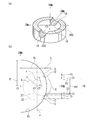
- the inside of the body 30 in this example has a spherical portion 34 whose inner peripheral surface is formed in a concave spherical shape, similar to the above-described hemispherical workpiece 13.
- FIG. 10A shows a longitudinal sectional view of the body 30 before the deburring process.
- the body 30 is formed in a one-piece structure from a material such as bronze, brass, or stainless steel, for example, and intersects the outflow ports 31 and 32 (corresponding to the through passage 16) corresponding to the through passage 16 and the outflow ports 31 and 32. And an exhaust port 33.
- a valve body accommodating portion 35 (corresponding to the spherical hollow portion 14) having a spherical surface portion 34 (corresponding to the spherical surface portion 15) is formed on a part of the inner periphery of the body 30, and on the upper side of the valve body accommodating portion 35.
- a shaft mounting portion 36 is provided, and an opening 37 is formed on the lower side so as to open.
- the outer shape 39 of the arcuate rotating body schematically shows a state in which the tip 3 of the arcuate rotating body of the tool body 1 according to the present invention is pressed against the intersecting ridge line portion 38.
- a circle 40 schematically shows the outer shape of a sphere (spherical tip) serving as a reference for the outer diameter 39.
- the auxiliary line 7 indicates the diameter axis of the circle 40, and the auxiliary line 6 corresponds to the rotation axis of the arcuate rotating body, that is, the rotation axis 4 in FIG.
- the eccentric distance ⁇ forming the arcuate rotating body of the tip 3 can be derived from the various values of the body 30 as described above.
- FIG. 10 (b) is a DD cross section of FIG. 10 (a) after deburring the intersecting ridge line portion 38 with the tip 3 of the tool body 1 of the present invention.
- the ridge line 41 is an intersecting line of the spherical portion 34 cut by the tip portion 3, and the cross-sectional view perpendicular to the central axis of the outflow inlet 31 (corresponding to the viewpoint ⁇ in FIG. 5), the outflow inlet 31 and the ridge line 41 are true. Shown in a circular shape.
- the surface formed between the ridge lines 41 and 42 is a processing surface 43 by deburring, and these correspond to the ridge lines 205 and 206 and the processing surface 204 in FIG.
- the surface width of the processed surface 43 is a substantially uniform deburring width over the entire circumference.
- FIG. 11A schematically shows a state in which a spherical tip formed in a single spherical shape is pressed against the intersecting ridge line portion 38, and the auxiliary line 7 corresponds to the diameter axis 21 described above.
- FIG. 11B is an EE cross section of FIG. 11A after deburring the intersecting ridge line portion 38 with the spherical tip portion.
- the ridge line 45 is an intersecting line of the spherical portion 34 cut by the tip portion 3, and the cross-sectional view perpendicular to the central axis of the outflow inlet 31 (corresponding to the viewpoint ⁇ in FIG. 5), the outflow inlet 31 has a perfect circle shape. Indicated.
- a surface formed between the ridge lines 42 ′ and 45 is a processing surface 46 by deburring, and these correspond to the ridge lines 202 and 201 and the processing surface 203 in FIG.
- the surface width of the processed surface 46 is a non-uniform surface width that is wide in width and narrow in length.
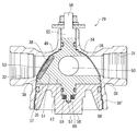
- FIG. 12 is a longitudinal sectional view in which a valve body 47 is attached to a body 30 ′ of another example of the rotary valve 29, and FIG. 13 is a perspective view of the appearance of the rotary valve 29.
- the rotary valve 29 is a valve suitable as, for example, a rapid exhaust valve for a railway vehicle.
- the same part as the said body 30 is attached
- the valve body 47 is inserted into the valve body storage part 35 through the opening 37 of the body 30 ′ and is rotatably mounted in a state of being positioned in the vertical direction.
- the valve body 47 is provided with a spherical surface portion 49 in part, and in this example, the outer peripheral surface of the valve body 47 is formed of a hemispherical spherical surface portion 49.
- a plurality of through-holes 50 that can communicate with the outflow inlets 31 and 32 or the exhaust outlet 33 are formed on the outer peripheral surface of the spherical surface portion 49 in three directions. , 32, or the exhaust groove 33 is formed.
- An elastic seal member 53 capable of closing the outflow inlets 31 and 32 or the exhaust port 33 is detachably mounted in the mounting groove 51.
- the mounting groove 51 is a circular concave groove
- the seal member 53 is formed in a disk shape that can be fitted into the circular concave groove 51.
- the through-hole 50 is formed in a full-bore shape having substantially the same diameter as the outflow inlets 31, 32 or the exhaust port 33, and pressure loss when communicating with the outflow ports 31, 32 or the exhaust port 33 is suppressed.
- An upper stem 55 to which the handle 54 can be attached is provided integrally or separately on the upper portion of the valve body 47, and a fitting projection 56 is formed at the handle mounting position of the upper stem 55.
- a lower stem 57 is integrally provided on the side facing the upper stem 55.
- the valve body 47 has a shape that can be inserted into the spherical portion 34, and in this case, the through port 50 and the seal member 53 rotate so as to face the outflow ports 31, 32, or the exhaust port 33, thereby passing the flow path. Switching is possible.
- the seal member 53 attached to the valve body 47 is formed of a polymer material such as PTFE (polytetrafluoroethylene) or PTFE containing carbon fiber.
- the seal member 53 rotates integrally with the valve body 47 when the valve body 47 is rotated, and can seal the outflow inlets 31, 32 or the exhaust port 33, respectively, while the outflow inlets 31, 32, or A fluid can be flowed when it deviates from the exhaust port 33.
- the lid member 58 is provided in a shape that allows the opening 37 to be covered via a thrust washer or the like, and a cylindrical portion 59 is formed on the outer periphery of the lid member 58.
- a spring member 60 whose upper and lower surfaces are made of disc springs is mounted, and the sealing member 53 is moved by the elastic force of the spring member 60.
- any one of the outflow inlets 31 and 32 or the exhaust port 33 is hermetically closed so that the outflow inlets 31 and 32 and the exhaust port 33 or the outflow ports 31 and 32 can communicate with each other through the through-hole 50. Is provided.
- the tool body 1 can be used for cross-hole deburring of a workpiece in which the hollow portion in the body has a spherical shape, so that it can also be used for a two-way valve, a three-way valve, a four-way valve, and the like. .
- the cylindrical surface workpiece 131 in this example has a cylindrical hollow portion 61 inside, and an inner peripheral surface of the cylindrical hollow portion 61 is a cylindrical surface portion 151 formed in a concave cylindrical surface shape. Yes.
- the tool body 1 of the present invention is used for the cylindrical surface portion 151.
- reference numeral 161 denotes a cylindrical through passage, the central axis of which is orthogonal to the central axis of the cylindrical surface portion 151, and a cross hole burr between the through passage 161 and the cylindrical surface portion 151 is a single.
- tip part formed in the spherical shape is shown.
- An intersecting line 62 indicates an intersecting line with the cylindrical surface 151 when the spherical tip is rotated and the ridge line 63 indicates an intersecting line with the inner surface 231 of the through-passage 161 when the spherical tip is rotated.
- the surface formed between the ridge line 62 and the ridge line 63 is the processed surface 64 by the spherical tip.
- the processed surface 64 has a non-uniform surface width in which the width in the vertical direction and the width in the horizontal direction are different from each other in the same manner as the processed surface 203 shown in FIG.
- FIG. 14B is a perspective view of the cylindrical workpiece 131 obtained by rotating and cutting the cross-hole burr between the cylindrical workpiece 131 and the through-hole 161 using the tool body 1 according to the present invention.
- the ridge line 65 indicates the intersection line with the cylindrical surface portion 151 when the cutting is performed at the tip 3 of the tool body 1
- the ridge line 66 indicates the intersection line with the inner surface 231 of the through-passage 161 when the tool body 1 is rotated.
- the surface formed between the ridge line 65 and the ridge line 66 is a processed surface 67 formed by the tip 3. Similar to the processed surface 204 shown in FIG. 8C, the processed surface 67 has a substantially uniform surface width over the entire circumference. As described above, when the tool body 1 according to the present invention is used for the cylindrical surface workpiece 131, deburring can be performed with a substantially uniform surface width.
- the eccentric distance ⁇ of the tip 3 of the tool body 1 used for the cylindrical surface workpiece 131 can be derived in the same manner as in the above-described hemispherical workpiece 13.
- the FF cross section is a plane including the central axis of the cylindrical workpiece 131 and the central axis of the through passage 161.
- the GG cross section is a plane that includes the central axis of the through passage 161 and is perpendicular to the FF cross section.
- the FF cross section is assumed to be the X′Y plane in FIG. 6B, and the deburring width is set to be the same in the Y axis direction up and down with respect to the through-passage 161, and the cylindrical workpiece A circle of a spherical tip portion having a radius S passing through 131 and deburring intersections A and B is arranged.
- the GG cross section is assumed to be the XZ plane of FIG.
- the left and right deburring width of the cylindrical workpiece 131 by the spherical tip is larger than the vertical deburring width. Therefore, as described above, the eccentric circle 27 passing through the intersection point E with C ′ and D ′ in FIG. 7B is set, and the X axis of the center point O ′ of the spherical tip and the center point O ′′ of the eccentric circle 27 is set.
- the direction distance is defined as an eccentric distance ⁇ . Since the eccentric distance ⁇ corresponds to the eccentric distance in FIG. 6B, the arcuate rotating body formed by rotating around the eccentric shaft 28 is formed into the shape of the tip portion 3, so that the diagonal of the machining surface is obtained.
- a tool body 1 with a substantially uniform deburring width (minor axis and major axis) can be obtained.
- the tangent angle ⁇ between the machining surface 67 and the cylindrical surface portion 151 shown in FIG. 14B is an obtuse angle, and can be adjusted to the shape of the tip portion where secondary burrs are unlikely to occur.
- FIG. 14C shows a half cut sectional view of a spool of an electromagnetic valve as an example of the cylindrical surface workpiece 131.
- Reference numeral 68 denotes a fluid outflow inlet
- 69 denotes a valve body that slides on the inner surface of the cylinder in the direction of the arrow.
- the valve body 69 has a structure that slides on the inner surface of the cylinder and seals the fluid between the inner surface of the cylinder and the valve body, and the intersection generated at the opening of the inner surface of the outflow inlet 68 in order to maintain the sealing performance.
- the hole burrs need not only be removed, but also have to be cut to a uniform surface width, particularly in the sliding direction.
- the tool body 1 according to the present invention can be applied to such a cross hole deburring process of the cylindrical inner surface opening, and there is also an effect of extending the life of the sliding part by processing to a uniform surface width.
- FIG. 15 shows a cylindrical surface workpiece 131 in which the through passage 161 intersects the central axis of the cylindrical inner surface 151 at an angle.
- reference numeral 70 denotes a ridge line of the pipe passage
- 71 denotes a ridge line of the cylindrical inner surface
- 72 denotes a processed surface.
- the tool body 1 according to the present invention can be applied to such a case.
Landscapes
- Engineering & Computer Science (AREA)
- Mechanical Engineering (AREA)
- General Engineering & Computer Science (AREA)
- Mining & Mineral Resources (AREA)
- Life Sciences & Earth Sciences (AREA)
- Geology (AREA)
- Physics & Mathematics (AREA)
- Environmental & Geological Engineering (AREA)
- Fluid Mechanics (AREA)
- General Life Sciences & Earth Sciences (AREA)
- Geochemistry & Mineralogy (AREA)
- Optics & Photonics (AREA)
- Plasma & Fusion (AREA)
- Milling Processes (AREA)
- Grinding And Polishing Of Tertiary Curved Surfaces And Surfaces With Complex Shapes (AREA)
- Milling, Broaching, Filing, Reaming, And Others (AREA)
Priority Applications (1)
| Application Number | Priority Date | Filing Date | Title |
|---|---|---|---|
| US15/518,075 US20170282258A1 (en) | 2014-10-14 | 2015-10-14 | Cross hole deburring tool, cross hole deburring method, and rotary valve machined by using the same |
Applications Claiming Priority (2)
| Application Number | Priority Date | Filing Date | Title |
|---|---|---|---|
| JP2014209637A JP6511245B2 (ja) | 2014-10-14 | 2014-10-14 | 交差穴バリ取り工具と交差穴バリ取り方法 |
| JP2014-209637 | 2014-10-14 |
Publications (1)
| Publication Number | Publication Date |
|---|---|
| WO2016060153A1 true WO2016060153A1 (ja) | 2016-04-21 |
Family
ID=55746696
Family Applications (1)
| Application Number | Title | Priority Date | Filing Date |
|---|---|---|---|
| PCT/JP2015/079001 Ceased WO2016060153A1 (ja) | 2014-10-14 | 2015-10-14 | 交差穴バリ取り工具と交差穴バリ取り方法並びにこれを用いて加工した回転弁 |
Country Status (3)
| Country | Link |
|---|---|
| US (1) | US20170282258A1 (https=) |
| JP (1) | JP6511245B2 (https=) |
| WO (1) | WO2016060153A1 (https=) |
Cited By (2)
| Publication number | Priority date | Publication date | Assignee | Title |
|---|---|---|---|---|
| CN107617769A (zh) * | 2017-10-27 | 2018-01-23 | 珠海艾诚精密模具有限公司 | 一种数控机床减少工件毛刺的加工方法 |
| CN111168131A (zh) * | 2019-12-13 | 2020-05-19 | 华东理工大学 | 一种用于去除交叉孔毛刺的刀具 |
Families Citing this family (8)
| Publication number | Priority date | Publication date | Assignee | Title |
|---|---|---|---|---|
| JP6325509B2 (ja) * | 2015-11-11 | 2018-05-16 | ファナック株式会社 | 工作機械 |
| DE102019203948B4 (de) * | 2019-03-22 | 2026-01-08 | Zf Friedrichshafen Ag | Vorrichtung und Verfahren zum Entgraten mindestens einer Bohröffnung eines metallischen Werkstücks |
| FR3097457B1 (fr) * | 2019-06-19 | 2021-07-09 | Safran Aircraft Engines | Procédé d’ébavurage amélioré de pièce aéronautique |
| DE102021110437A1 (de) * | 2020-04-27 | 2021-10-28 | Illinois Tool Works Inc. | Ventil |
| CN112404506A (zh) * | 2020-11-12 | 2021-02-26 | 阿伐流体控制有限公司 | 一种阀球固定装置以及轴孔加工装置 |
| US11953080B1 (en) | 2021-09-24 | 2024-04-09 | Apple Inc. | Shaft with surface finished ridges |
| JP7071778B1 (ja) * | 2022-01-14 | 2022-05-19 | 株式会社ジーベックテクノロジー | バリ取り工具、およびバリ取り方法 |
| CN114850548B (zh) * | 2022-04-25 | 2024-06-25 | 成都四威高科技产业园有限公司 | 太赫兹波导口部毛刺去除工艺 |
Citations (3)
| Publication number | Priority date | Publication date | Assignee | Title |
|---|---|---|---|---|
| JPH0979391A (ja) * | 1995-09-14 | 1997-03-25 | Fanenshumitto Arnold | ボールバルブ |
| JP2005074523A (ja) * | 2003-08-29 | 2005-03-24 | Yamashita Kikai Kk | バリ取り用工具 |
| JP2012002355A (ja) * | 2010-05-20 | 2012-01-05 | Kitz Corp | 回転弁 |
-
2014
- 2014-10-14 JP JP2014209637A patent/JP6511245B2/ja active Active
-
2015
- 2015-10-14 WO PCT/JP2015/079001 patent/WO2016060153A1/ja not_active Ceased
- 2015-10-14 US US15/518,075 patent/US20170282258A1/en not_active Abandoned
Patent Citations (3)
| Publication number | Priority date | Publication date | Assignee | Title |
|---|---|---|---|---|
| JPH0979391A (ja) * | 1995-09-14 | 1997-03-25 | Fanenshumitto Arnold | ボールバルブ |
| JP2005074523A (ja) * | 2003-08-29 | 2005-03-24 | Yamashita Kikai Kk | バリ取り用工具 |
| JP2012002355A (ja) * | 2010-05-20 | 2012-01-05 | Kitz Corp | 回転弁 |
Cited By (3)
| Publication number | Priority date | Publication date | Assignee | Title |
|---|---|---|---|---|
| CN107617769A (zh) * | 2017-10-27 | 2018-01-23 | 珠海艾诚精密模具有限公司 | 一种数控机床减少工件毛刺的加工方法 |
| CN111168131A (zh) * | 2019-12-13 | 2020-05-19 | 华东理工大学 | 一种用于去除交叉孔毛刺的刀具 |
| CN111168131B (zh) * | 2019-12-13 | 2021-08-03 | 华东理工大学 | 一种用于去除交叉孔毛刺的刀具 |
Also Published As
| Publication number | Publication date |
|---|---|
| US20170282258A1 (en) | 2017-10-05 |
| JP6511245B2 (ja) | 2019-05-15 |
| JP2016078139A (ja) | 2016-05-16 |
Similar Documents
| Publication | Publication Date | Title |
|---|---|---|
| WO2016060153A1 (ja) | 交差穴バリ取り工具と交差穴バリ取り方法並びにこれを用いて加工した回転弁 | |
| US11292147B2 (en) | Methods of cutting fiber reinforced polymer composite workpieces with a pure waterjet | |
| JP5646623B2 (ja) | 削り出しエルボとその製造方法 | |
| CN105209221B (zh) | 倒角加工方法 | |
| CN103713576B (zh) | 多轴铣削加工工件表面形貌建模方法 | |
| CN106853598A (zh) | 一种虚拟球刀半径的圆柱形砂轮曲面磨削方法 | |
| WO2018037804A1 (ja) | 切削インサート及び刃先交換式回転切削工具 | |
| CN111390505B (zh) | 采用九轴机床加工辊的方法及利用该方法生产的辊 | |
| CN103962616A (zh) | 一种用于加工复杂曲面的正交螺旋形切削刃椭球头铣刀 | |
| JPWO2018037804A1 (ja) | 切削インサート及び刃先交換式回転切削工具 | |
| JP4644259B2 (ja) | 加工工具および加工方法 | |
| JP2017124460A (ja) | カップ状砥石による被加工物の非球面形状の連続加工方法及びその装置 | |
| JP3662087B2 (ja) | 曲面切削加工方法 | |
| JPH02303707A (ja) | ボールエンドミル | |
| JP4122127B2 (ja) | 砥石溝入れ装置 | |
| JP2007245338A (ja) | ミリングカッタ | |
| CN113324082A (zh) | 一种球阀左阀体零件及其数控加工方法 | |
| CN105965077A (zh) | 一种切向锥鼓铣刀 | |
| CN206732222U (zh) | 一种球头铣刀 | |
| JPH0639610A (ja) | スローアウェイチップおよび切削工具 | |
| JP2003205414A (ja) | センタ穴を有する被覆部材およびその被覆方法 | |
| JPH04101701A (ja) | 球面着座部をもつバルブプラグの加工方法 | |
| CN106424884A (zh) | 一种加工凸r的外型轮廓刀具 | |
| JP2008110458A (ja) | 円弧刃を有するエンドミルの製造方法 | |
| TWM598195U (zh) | 旋轉進給裝置及具有旋轉進給裝置的加工機 |
Legal Events
| Date | Code | Title | Description |
|---|---|---|---|
| 121 | Ep: the epo has been informed by wipo that ep was designated in this application |
Ref document number: 15849859 Country of ref document: EP Kind code of ref document: A1 |
|
| DPE1 | Request for preliminary examination filed after expiration of 19th month from priority date (pct application filed from 20040101) | ||
| WWE | Wipo information: entry into national phase |
Ref document number: 15518075 Country of ref document: US |
|
| NENP | Non-entry into the national phase |
Ref country code: DE |
|
| 122 | Ep: pct application non-entry in european phase |
Ref document number: 15849859 Country of ref document: EP Kind code of ref document: A1 |