WO2016059860A1 - 情報処理システム、情報処理装置、および情報処理端末 - Google Patents
情報処理システム、情報処理装置、および情報処理端末 Download PDFInfo
- Publication number
- WO2016059860A1 WO2016059860A1 PCT/JP2015/072573 JP2015072573W WO2016059860A1 WO 2016059860 A1 WO2016059860 A1 WO 2016059860A1 JP 2015072573 W JP2015072573 W JP 2015072573W WO 2016059860 A1 WO2016059860 A1 WO 2016059860A1
- Authority
- WO
- WIPO (PCT)
- Prior art keywords
- information processing
- information
- identification information
- light source
- input
- Prior art date
Links
Images


Classifications
-
- G—PHYSICS
- G06—COMPUTING; CALCULATING OR COUNTING
- G06F—ELECTRIC DIGITAL DATA PROCESSING
- G06F21/00—Security arrangements for protecting computers, components thereof, programs or data against unauthorised activity
- G06F21/30—Authentication, i.e. establishing the identity or authorisation of security principals
- G06F21/31—User authentication
- G06F21/34—User authentication involving the use of external additional devices, e.g. dongles or smart cards
-
- G—PHYSICS
- G06—COMPUTING; CALCULATING OR COUNTING
- G06Q—INFORMATION AND COMMUNICATION TECHNOLOGY [ICT] SPECIALLY ADAPTED FOR ADMINISTRATIVE, COMMERCIAL, FINANCIAL, MANAGERIAL OR SUPERVISORY PURPOSES; SYSTEMS OR METHODS SPECIALLY ADAPTED FOR ADMINISTRATIVE, COMMERCIAL, FINANCIAL, MANAGERIAL OR SUPERVISORY PURPOSES, NOT OTHERWISE PROVIDED FOR
- G06Q40/00—Finance; Insurance; Tax strategies; Processing of corporate or income taxes
- G06Q40/02—Banking, e.g. interest calculation or account maintenance
-
- G—PHYSICS
- G07—CHECKING-DEVICES
- G07D—HANDLING OF COINS OR VALUABLE PAPERS, e.g. TESTING, SORTING BY DENOMINATIONS, COUNTING, DISPENSING, CHANGING OR DEPOSITING
- G07D9/00—Counting coins; Handling of coins not provided for in the other groups of this subclass
-
- H—ELECTRICITY
- H04—ELECTRIC COMMUNICATION TECHNIQUE
- H04N—PICTORIAL COMMUNICATION, e.g. TELEVISION
- H04N1/00—Scanning, transmission or reproduction of documents or the like, e.g. facsimile transmission; Details thereof
- H04N1/00127—Connection or combination of a still picture apparatus with another apparatus, e.g. for storage, processing or transmission of still picture signals or of information associated with a still picture
- H04N1/00204—Connection or combination of a still picture apparatus with another apparatus, e.g. for storage, processing or transmission of still picture signals or of information associated with a still picture with a digital computer or a digital computer system, e.g. an internet server
-
- G—PHYSICS
- G06—COMPUTING; CALCULATING OR COUNTING
- G06F—ELECTRIC DIGITAL DATA PROCESSING
- G06F21/00—Security arrangements for protecting computers, components thereof, programs or data against unauthorised activity
- G06F21/30—Authentication, i.e. establishing the identity or authorisation of security principals
- G06F21/31—User authentication
- G06F21/32—User authentication using biometric data, e.g. fingerprints, iris scans or voiceprints
-
- H—ELECTRICITY
- H04—ELECTRIC COMMUNICATION TECHNIQUE
- H04N—PICTORIAL COMMUNICATION, e.g. TELEVISION
- H04N1/00—Scanning, transmission or reproduction of documents or the like, e.g. facsimile transmission; Details thereof
- H04N1/00127—Connection or combination of a still picture apparatus with another apparatus, e.g. for storage, processing or transmission of still picture signals or of information associated with a still picture
-
- H—ELECTRICITY
- H04—ELECTRIC COMMUNICATION TECHNIQUE
- H04N—PICTORIAL COMMUNICATION, e.g. TELEVISION
- H04N1/00—Scanning, transmission or reproduction of documents or the like, e.g. facsimile transmission; Details thereof
- H04N1/32—Circuits or arrangements for control or supervision between transmitter and receiver or between image input and image output device, e.g. between a still-image camera and its memory or between a still-image camera and a printer device
- H04N1/32101—Display, printing, storage or transmission of additional information, e.g. ID code, date and time or title
Definitions
- This disclosure relates to an information processing system, an information processing apparatus, and an information processing terminal.
- an information processing apparatus having a user authentication function has been installed in convenience stores, stations, public facilities, and the like.
- Such an information processing apparatus can provide a dedicated service to the authenticated user.
- an automatic transaction apparatus Automatic Teller Machine: ATM
- a ticket issuing machine such as a concert ticket
- an automatic issuing machine such as a certificate
- the information processing apparatus as described above is installed in a place where an unspecified number of users can operate. Therefore, for example, there is a possibility that a camera or the like for voyeurism is set in the input unit, and user authentication information input to the information processing apparatus by the user is stolen (so-called skimming).
- Patent Documents 1 to 5 an information processing apparatus capable of inputting information or displaying information via a mobile communication terminal or the like possessed by the user is proposed.
- Patent Literature 1 when a two-dimensional code image is displayed on an information processing apparatus and the image is captured by a mobile communication terminal, user authentication information corresponding to the captured two-dimensional code image is displayed as a user.
- An information processing system for transmitting to an authentication server is disclosed.
- Patent Document 2 discloses an automatic transaction apparatus that stores executed transaction result information in another server, and displays a two-dimensional code image including information indicating a storage destination of the transaction result information on a display unit. ing.
- Patent Documents 3 to 5 a two-dimensional code image obtained by converting user information or transaction content information necessary for authentication is displayed on a mobile communication terminal, and an automatic transaction apparatus (ATM) reads the image to perform transaction.
- ATM automatic transaction apparatus
- Patent Documents 1 to 5 use a two-dimensional code image for information transmission between the information processing apparatus and the mobile communication terminal, if the displayed two-dimensional code image is voyeurized, two There is a possibility that information contained in the dimension code image is stolen. Therefore, there has been a demand for an information processing system using communication means in which information is not easily stolen by information transmission between the information processing apparatus and the mobile communication terminal.
- the present disclosure proposes a new and improved information processing system, information processing apparatus, and information processing terminal with improved security.
- an information processing device including a visible light communication control unit that controls a light emission state of the light source based on identification information of the light source and the information processing device and transmits the identification information, an imaging unit, An identification information acquisition unit that performs image processing on the image of the light source imaged by the imaging unit and acquires identification information of the information processing device, and an input screen on which an operation for the information processing device is input based on the identification information
- An information processing system includes: a display control unit that controls display; and an information processing terminal that includes an input information transmission unit that transmits input information input to the input screen to the information processing device.
- an information processing apparatus provided with the light source and the visible light communication control part which controls the light emission state of the said light source based on the identification information of an information processing apparatus, and transmits the said identification information is provided. Is done.
- the identification information acquisition that acquires the identification information of the information processing apparatus that performs image processing on the image captured by the imaging unit and the image capturing unit and is transmitted according to the light emission state of the light source of the information processing apparatus
- a display control unit that controls display of an input screen on which an operation on the information processing device is input based on the identification information, and an input that transmits the input information input on the input screen to the information processing device
- An information processing terminal comprising an information transmission unit is provided.
- the information processing terminal receives the identification information of the information processing device through visible light communication that is difficult to steal information by voyeurism or the like, and displays an input screen corresponding to the information processing device. Further, the information processing terminal transmits an input operation input on the input screen to the information processing apparatus, and the information processing apparatus executes processing based on the transmitted input operation. Thereby, the user can perform an input operation to the information processing apparatus using the information processing terminal.
- FIG. 12 is a flowchart for explaining an operation flow of the information processing system when identification information cannot be acquired. It is explanatory drawing explaining the global shutter operation
- Information processing system according to an embodiment of the present disclosure 1.1. Configuration of information processing system 1.2. Configuration of information processing terminal and information processing apparatus 1.3. Operation of information processing system Identification information acquisition method 2.1. First acquisition method 2.2. Second acquisition method 2.3. 3. Third acquisition method 3. Hardware configuration according to an embodiment of the present disclosure Summary
- the information processing system according to the present embodiment performs an input operation to the information processing apparatus by the information processing terminal when the information processing terminal possessed by the user receives the identification information transmitted by visible light communication. It is.
- the information processing terminal may be, for example, a mobile communication terminal such as a mobile phone and a smartphone, or a PDA (Personal Digital Assistant).
- the information processing apparatus may be an apparatus that provides a service requiring user authentication, such as an automatic transaction apparatus (ATM), a ticket issuing machine such as a concert ticket, and an automatic issuing machine such as a certificate.
- ATM automatic transaction apparatus
- ticket issuing machine such as a concert ticket
- an automatic issuing machine such as a certificate.
- ATM automatic transaction apparatus
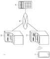
- FIG. 1 is an explanatory diagram illustrating the overall configuration of the information processing system according to the present embodiment.
- the information processing system 1 includes an information processing terminal 11, an information processing device 13, a network 15, and a financial institution server 17. Further, a plurality of information processing devices 13 may be provided.
- the information processing terminal 11 is, for example, a mobile phone or a smartphone owned by the user, and includes an imaging unit such as a camera.
- the information processing terminal 11 can acquire the identification information by capturing the identification information of the information processing apparatus 13 transmitted as a change in the light emission state of the light source by the imaging unit and performing image processing on the captured image.
- the information processing terminal 11 displays an input screen on which an operation on the information processing device 13 can be input based on the acquired identification information, and transmits the operation input on the input screen to the information processing device 13. . Thereby, the user can perform an input operation to the information processing apparatus 13 on the information processing terminal 11.
- the information processing apparatus 13 is an automatic transaction apparatus installed in, for example, a bank or a convenience store, and includes a light source.
- the information processing device 13 can encode its own identification information and transmit the encoded identification information to the information processing terminal 11 by a change in the light emission state of the light source.
- the light source may be a display device that displays an image or the like, and the information processing device 13 transmits identification information to the information processing terminal 11 by changing the luminance or hue of the image displayed on the display device. May be.
- the change in the light emission state of the light source by the information processing device 13 is performed at a frequency that is so high that it cannot be recognized by human vision.
- the frequency that cannot be recognized by human vision is, for example, 70 Hz or more, and the information processing device 13 controls the light emission state of the light source at, for example, about 10 kHz.
- the information processing apparatus 13 can transmit information to the information processing terminal 11 by a communication means that is not visually recognized by the user.
- the information processing device 13 executes various transactions based on the user input operation transmitted from the information processing terminal 11.
- the information processing apparatus 13 may execute various transactions that can be normally executed as an automatic transaction apparatus such as deposit withdrawal, deposit of cash, and balance inquiry.
- the network 15 is a dedicated network possessed by a financial institution, and is configured by, for example, an IP-VPN (Internet Protocol-Virtual Private Network).
- IP-VPN Internet Protocol-Virtual Private Network
- the network 15 may be a wired or wireless LAN (Local Area Network) as long as it is a dedicated network that is not open to the public.
- the financial institution server 17 is, for example, a host server of a financial institution and controls various transactions in each information processing apparatus 13.
- the financial institution server 17 authenticates a user who operates the information processing apparatus 13, or executes transaction processing such as deposit / withdrawal and transfer instructed by the user's operation.
- the financial institution server 17 manages customer information such as an account number, personal identification number, name, address, age, date of birth, telephone number, occupation, family structure, annual income, and deposit balance as an account ledger.
- the information processing apparatus 13 transmits identification information by changing the light emission state of the light source. Further, the information processing terminal 11 acquires an identification information of the information processing apparatus 13 by capturing an image of the light source with a camera or the like and acquiring a change in the light emission state of the light source, and corresponds to the acquired identification information. Display the input screen.
- the information processing terminal 11 establishes a communication connection with the information processing apparatus 13 that has acquired the identification information, and transmits an input operation input on the input screen by the user to the information processing apparatus 13. Further, the information processing apparatus 13 executes a transaction based on the input operation transmitted from the information processing terminal 11. With the above operation, the user can perform an input operation on the information processing apparatus 13 using the information processing terminal 11.
- the user can perform an input operation to the information processing apparatus 13 using the information processing terminal 11. Further, in the information processing system 1, visible light communication that is not visually recognized is used without using a visually recognizable two-dimensional code image for information transmission between the information processing terminal 11 and the information processing device 13. For this reason, in the information processing system 1, since the input information is not easily skimmed, the security can be further improved.
- a communication method for transmitting information according to a change in the light emission state of a light source is also called visible light communication.
- a communication method for receiving information by imaging a change in the light emission state of a light source with an imaging unit such as a camera is also called image sensor communication.
- Such a communication method transmits information according to a change in the light emission state of the light source, the user can easily grasp the transmission source and the communication range.
- the information processing device 13 that performs visible light communication with the information processing terminal 11 of the user is limited to the information processing device 13 that can capture the light source at the information processing terminal 11 of the user, the user can It is easy to understand intuitively when the visible light communication is performed with the information processing apparatus 13 installed in the network. Therefore, the user can easily grasp the information processing apparatus 13 with which he / she is communicating even in a place where a large number of information processing apparatuses 13 are installed. Therefore, according to such a communication method, it is possible to prevent the user from operating the information processing apparatus 13 that is not intended.
- the range in which the change in the light emission state of the light source can be imaged is in the vicinity of the information processing apparatus 13 (approximately within 3 m from the light source), and the communicable range is also in the same range. . Therefore, the information processing terminal 11 can determine that the information processing terminal 11 has left the information processing apparatus 13 when the visible light communication becomes impossible by monitoring the communication state of the visible light communication at a predetermined timing. . As a result, when the information processing terminal 11 leaves the information processing apparatus 13, the information processing terminal 11 stops displaying the operation input screen for the information processing apparatus 13, and the information processing apparatus 13 is operated from a remote position. Can be prevented.
- the information processing system 1 according to the present embodiment can further improve security.
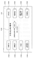
- FIG. 2 is a block diagram illustrating the internal configuration of the information processing terminal 11 and the information processing apparatus 13 according to the present embodiment.
- the information processing terminal 11 includes an imaging unit 111, an identification information acquisition unit 112, a display control unit 113, a display storage unit 114, a display unit 115, an input unit 116, and input information transmission. Part 117.
- the information processing apparatus 13 includes a light source 131, a visible light communication control unit 132, a storage unit 133, an input information receiving unit 134, a communication unit 135, and a transaction execution unit 136.
- the imaging unit 111 includes an imaging lens, an imaging element, and the like, and acquires an image of a subject (more specifically, a light source 131). Specifically, the imaging unit 111 is configured to capture an image from a subject incident through an imaging lens by an imaging device such as a complementary metal-oxide semiconductor (CMOS) image sensor or a charge-coupled device (CCD) image sensor. Light is photoelectrically converted into an image signal.
- CMOS complementary metal-oxide semiconductor
- CCD charge-coupled device
- the identification information acquisition unit 112 acquires the identification information of the information processing device 13 by performing image processing on the image of the light source 131 captured by the imaging unit 111. Specifically, the identification information acquisition unit 112 detects a time-series change in the light emission state such as the luminance or hue of the light source 131 from the image captured by the imaging unit 111, and identifies the detected change in the light emission state as the identification information. Convert to
- the identification information acquisition unit 112 can acquire identification information regardless of the direction of the light source 131 if the light source 131 is included in the captured image. Further, the identification information acquisition unit 112 acquires the identification information if the light source 131 as a display device is included in about 1/4 to 1/3 of the entire captured image, depending on the performance of the imaging unit 111. can do.
- the identification information acquisition unit 112 may acquire the identification information of the information processing device 13 from the image of the light source 131 captured at a predetermined timing, and may confirm the state of visible light communication with the information processing device 13. .
- the identification information acquisition unit 112 performs information processing from an image captured at a predetermined timing by the imaging unit 111 while the input screen for the information processing device 13 is displayed on the display unit 115 by the display control unit 113. You may confirm whether the identification information of the apparatus 13 can be acquired.
- the display control unit 113 may stop displaying the input screen on the information processing device 13. According to such a configuration, the information processing terminal 11 can prevent the user from operating the information processing device 13 from a position that is so far away that the information processing device 13 cannot be visually recognized.
- the predetermined timing is, for example, an interval of about several seconds.
- the identification information acquisition unit 112 may always check whether or not the identification information of the information processing apparatus 13 can be acquired from the captured image of the light source 131.
- the predetermined time is, for example, about several seconds, similarly to the predetermined timing.
- the display control unit 113 controls display of an input screen for inputting an operation to the information processing device 13 based on the identification information of the information processing device 13 acquired by the identification information acquisition unit 112. For example, the display control unit 113 generates an input screen imitating the operation screen displayed on the information processing device 13 based on the identification information of the information processing device 13, and performs control for displaying the input screen on the display unit 115. Do. When the information processing device 13 sequentially displays a plurality of operation screens until the completion of the transaction, the display control unit 113 similarly controls the display unit 115 to sequentially display the plurality of input screens. Also good.
- the display storage unit 114 stores information on an input screen whose display is controlled by the display control unit 113. Specifically, the display storage unit 114 stores information for generating an input screen on which an operation on the information processing device 13 is input. Further, the display storage unit 114 may store generation information of a corresponding input screen for each information processing device 13 or for each financial institution to which the information processing device 13 belongs. Here, when the operation with respect to the information processing device 13 needs to be input over a plurality of input screens before the completion of the transaction, the display storage unit 114 may store information on the plurality of input screens, respectively.
- the display unit 115 is a display device whose display is controlled by the display control unit 113.
- the display unit 115 may be an LCD (Liquid Crystal Display) device, an OLED (Organic Light-Emitting Display) device, or the like.
- the input unit 116 is an input device for a user to input information, such as a mouse, a keyboard, a button, a microphone, a switch, or a lever.
- a user who has confirmed the input screen displayed on the display unit 115 can input an operation on the information processing apparatus 13 by operating the input unit 116.
- the input information input via the input unit 116 is transmitted to the information processing apparatus 13 by the input information transmitting unit 117.
- the input information transmission unit 117 communicates with the information processing device 13. Specifically, the input information transmission unit 117 transmits the input information input to the input unit 116 to the input information reception unit 134 of the information processing device 13.
- the input information includes, for example, information indicating transaction details executed by the information processing apparatus 13 and user personal authentication information. Therefore, in order to further improve the security of the information processing system 1, it is preferable that the input information transmission unit 117 encrypts and transmits the input information.
- the input information transmission unit 117 may be any communication interface as long as it can transmit information to the information processing device 13, and may be a wireless communication device, for example. However, in order to further improve the security of the information processing system 1, it is preferable that the input information transmission unit 117 transmits the input information to the information processing apparatus 13 by a communication means with higher confidentiality. For example, the input information transmission unit 117 may transmit the input information to the information processing apparatus 13 by visible light communication, similarly to the light source 131.
- the light source 131 is an illumination or display device capable of controlling the light emission state, and is preferably a display device. Further, the luminance or hue of the light source 131 is controlled by the visible light communication control unit 132. Therefore, the light source 131 can transmit identification information encoded by time-series changes in luminance or hue to the information processing terminal 11.
- the light source 131 is a light source capable of changing luminance or hue at a high frequency (for example, 70 Hz or more) such that flicker cannot be recognized by human vision.
- a high frequency for example, 70 Hz or more
- Examples of the light source that can change the luminance or the hue at such a high frequency include an LED (Light Emitting Diode) light source, an organic EL (ElectroLuminescence) light source, and the like.
- the above-described light source may be used as a backlight of the display device or may be used as a pixel of the display device, for example.
- the visible light communication control unit 132 controls the light emission state of the light source 131 based on the identification information of the information processing device 13. Specifically, the visible light communication control unit 132 encodes the identification information of the information processing device 13 and transmits the encoded identification information by controlling the luminance or hue of the light source 131.
- FIG. 3 is an explanatory diagram for schematically explaining visible light communication.
- the visible light communication control unit 132 encodes the identification information of the information processing apparatus 13 into binary information such as “0” and “1”.
- the visible light communication control unit 132 changes the luminance of the light source 131 (more specifically, the display device) of the information processing device in time series based on the encoded identification information.
- the visible light communication control unit 132 may control the light emission state of the light source by setting “1” as the luminance “high” state and “0” as the luminance “low” state.
- the information processing terminal 11 the light source 131 whose brightness changes in time series (more specifically, the display device) is imaged by the imaging unit 111, thereby detecting the time series change in brightness of the light source 131.
- the information processing terminal 11 stores in advance the correspondence between the brightness control by the visible light communication control unit 132 and the identification information “0” and “1”, and based on the correspondence, the light source 131. Is converted into encoded identification information. Thereby, the information processing terminal 11 can acquire the identification information of the information processing device 13 by visible light communication.
- the change in the luminance of the visible light communication control unit 132 is controlled at a frequency (for example, 10 kHz) higher than the response speed of human vision. Changes are integrated and cannot be recognized. Therefore, the visible light communication control unit 132 can transmit the identification information of the information processing apparatus 13 by communication means that is not recognized by the user and does not feel flicker or the like.
- the visible light communication control unit 132 may transmit the identification information by a change in the hue of the light source 131. Human vision is less sensitive to changes in hue than luminance. Therefore, when the visible light communication control unit 132 transmits the identification information not by the luminance change of the light source 131 but by the hue change, the identification information can be transmitted without being recognized by the user even at a lower frequency.
- the visible light communication control unit 132 modulates the hue of the light source 131 in time series between hues of complementary colors such as red and green, yellow and blue, for example, in the same manner as the luminance change.
- the identification information of the information processing device 13 can be transmitted.
- the visible light communication control unit 132 may change the luminance or hue of the light source 131 by controlling the luminance or hue of the backlight.
- the technology of the present disclosure is not limited to such an example, and the visible light communication control unit 132 performs image processing on a displayed image and controls the luminance or hue of the light source 131 by controlling the luminance or hue of the image itself. May be changed.
- the visible light communication control unit 132 may repeatedly transmit the identification information of the information processing device 13 using the same encoding method, or may transmit the identification information encoding method while dynamically changing the information. Good.
- the storage unit 133 stores identification information of the information processing apparatus 13.
- the storage unit 133 may store programs and databases for various processes executed by the information processing apparatus 13, and stores various parameters and intermediate processes that need to be saved when performing various processes. May be.
- the input information receiving unit 134 communicates with the information processing terminal 11. Specifically, the input information receiving unit 134 receives input information for instructing an operation on the information processing apparatus 13 transmitted from the input information transmitting unit 117 of the information processing terminal 11.
- the input information includes, for example, information indicating transaction details executed by the information processing device 13 and user personal authentication information.
- the information processing device 13 is based on the input information received by the input information receiving unit 134. Execute the transaction.
- the input information receiving unit 134 may be any communication interface as long as it can receive information from the input information transmitting unit 117, and may be a wireless communication device, for example. However, in order to further improve the security of the information processing system 1, it is preferable that the input information receiving unit 134 receives the input information from the information processing terminal 11 by a communication means with higher confidentiality. For example, the input information receiving unit 134 may receive the input information through visible light communication as with the imaging unit 111.
- the communication unit 135 communicates various information necessary for executing transactions with the financial institution server 17 via the network 15. Specifically, the communication unit 135 transmits the transaction content information and the user personal authentication information to the financial institution server 17 and receives the transaction result.
- the communication unit 135 may be any communication interface as long as it is a communication interface configured with a communication device or the like for connecting to the network 15.
- the communication unit 135 may be a communication device that can be connected to the network 15 wirelessly or by wire, may be a wired LAN or a wireless LAN compatible communication device, or is a wire communication device that performs wired communication. May
- the transaction execution unit 136 has a function of executing various transactions performed by a general automatic transaction apparatus, and executes various transactions based on the input information received by the input information receiving unit 134. Specifically, the transaction executing unit 136 executes various transactions such as deposit withdrawal, cash deposit, and balance inquiry by the user's operation based on the input information received by the input information receiving unit 134.
- the information processing system 1 can perform an input operation to the information processing apparatus 13 on the information processing terminal 11.
- the information processing system 1 since information transmission between the information processing terminal 11 and the information processing apparatus 13 is not visually recognized and dynamically changes, and visible light communication that is difficult to skimming is used, the information processing system 1 further improves security. be able to.
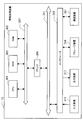
- FIG. 4 is a flowchart for explaining the operation flow of the information processing system 1 according to the present embodiment.
- the user performs an activation operation of the imaging unit 111 of the information processing terminal 11 (S101), and the imaging unit 111 is activated (S103).
- the imaging unit 111 images the light source 131 of the information processing apparatus 13, and the identification information is acquired by the image processing of the identification information acquisition unit 112 (S105-1).
- the acquired identification information is notified to the display control unit 113, and the display control unit 113 transmits a wireless connection request to the information processing apparatus 13 (S109) and receives a connection response from the information processing apparatus 13. (S111).
- the information processing terminal 11 may transmit the user authentication information to the information processing apparatus 13 together.
- the display control unit 113 controls the display of the input screen displayed on the display unit 115 based on the identification information to the information processing device 13 (S113).
- the user performs an input operation on the input screen displayed on the display unit 115 (S115-1), and the display control unit 113 controls the display of the input screen in response to the user's input operation (S117). -1).
- the user and display control unit 113 repeats such user input operations (S115-1 to N) and input screen display controls (S117-1 to N) until the transaction is confirmed.
- the imaging unit 111 and the identification information acquisition unit 112 are configured to start from an image captured by the imaging unit 111 at a predetermined timing (for example, every few seconds or always) while the user performs an input operation on the input screen. It is confirmed whether or not the identification information of the information processing apparatus 13 can be acquired (S105-2 to N). Thereby, the information processing terminal 11 confirms that the user is not away from the information processing apparatus 13. The imaging unit 111 and the identification information acquisition unit 112 repeat this operation until a transaction is confirmed in the display control unit 113. The case where the identification information is not acquired by the imaging unit 111 and the identification information acquisition unit 112 will be described later with reference to FIG.
- the display control unit 113 uses the information indicating the operation on the information processing device 13 input on the input screen as the transaction execution request.
- the data is transmitted to the processing device 13 (S121).
- the user authentication information may be transmitted to the information processing apparatus 13 together with the transaction execution request.
- the information processing apparatus 13 After transmitting the transaction execution request received from the information processing terminal 11 to the financial institution server 17 (S123), the information processing apparatus 13 receives a transaction execution instruction from the financial institution server 17 (S125), and makes a transaction to the user. Execute (S127).
- the executed transaction is, for example, cash withdrawal, cash deposit, balance inquiry, or transfer.
- the information processing apparatus 13 transmits a transaction end notification to the information processing terminal 11 by visible light communication using the light source 131 ( S131).
- the information processing terminal 11 receives the transaction end notification at the imaging unit 111, the information processing terminal 11 notifies the display control unit 113 of the end of the transaction (S133), and ends the display of the input screen.
- the imaging unit 111 stops the function (S137).
- the information processing system 1 can provide a service with improved security to the user.
- FIG. 5 is a flowchart for explaining the operation flow of the information processing system 1 when the identification information cannot be acquired.
- the identification information acquisition unit 112 displays the display control unit. 113 is notified of the cancellation of the display of the input screen (S203). Therefore, the display control unit 113 stops displaying the input screen (S205) and stops the function, thereby preventing a transaction from being executed from a place away from the information processing apparatus 13.
- the predetermined time may be about several seconds like the predetermined timing.
- the imaging unit 111 stops the function ( S137).
- the information processing system 1 can prevent the user from operating the information processing apparatus 13 at a place away from the information processing apparatus 13. Further, in the information processing system 1 according to the present embodiment, when the user loses the information processing terminal 11 during the operation of the information processing terminal 11, the lost information processing terminal 11 instructs the information processing apparatus 13 to execute a transaction. Can be prevented.
- the information processing system 1 has been described in detail above.
- the method by which the identification information acquisition unit 112 acquires identification information from the image of the light source 131 is based on the following first to second types depending on the imaging method of the imaging unit 111 and the type of image of the light source 131 (more specifically, the display device). 3 acquisition methods.
- the imaging unit 111 images the light source 131 by the global shutter operation, and the imaging frame rate of the imaging unit 111 is higher than the frequency at which the visible light communication control unit 132 controls the light emission state of the light source 131. This is a method for acquiring identification information in a fast case.
- FIG. 6 is an explanatory diagram illustrating a global shutter operation in the imaging apparatus.
- the global shutter operation is one of shutter operations in the image pickup apparatus, and is a shutter operation in which all pixels of the image pickup apparatus perform image pickup at the same time. As shown in FIG. 6, in an imaging apparatus that performs a global shutter operation, when imaging one frame, for example, pixels in all lines start exposure at the same time and end exposure at the same time.
- the image captured by such a global shutter operation is captured as an image having a uniform light emission state in the entire image because the pixels in all the lines reflect the light emission state of the light source 131 in the same period.
- the imaging unit 111 that performs the global shutter operation acquires the change in the light emission state of the light source 131 by setting the imaging frame rate faster than the control frequency of the light emission state of the light source 131 by the visible light communication control unit 132. Can do.
- the imaging unit 111 that performs a global shutter operation can detect a change in the light emission state of the light source 131 by setting the sampling frequency for imaging higher than the control frequency of the light emission state of the light source 131. Therefore, the identification information acquisition unit 112 can acquire the identification information of the information processing device 13 from the change in the light emission state of the light source 131.
- the second acquisition method is an identification information acquisition method when the imaging unit 111 images the light source 131 by a rolling shutter operation.
- the identification information acquisition unit 112 Identification information of the information processing apparatus 13 can be acquired.
- FIG. 7 is an explanatory diagram illustrating a rolling shutter operation in the imaging apparatus.
- the rolling shutter operation is one of the shutter operations in the imaging device, and is a shutter operation in which the pixels of the imaging device sequentially perform imaging for each pixel group (for example, line).
- a shutter operation in which the pixels of the imaging device sequentially perform imaging for each pixel group (for example, line).
- FIG. 7 in an imaging apparatus that performs a rolling shutter operation, when one frame is imaged, exposure is started sequentially from top to bottom for each pixel of each line. More specifically, the exposure of the pixels of each line is started in order at intervals of time t, and the exposure is sequentially terminated after a certain exposure time has elapsed.
- the image captured by such a rolling shutter operation reflects the light emission state of the light source 131 during the period in which the pixels of each line are different. Therefore, when the light emission state of the light source 131 changes in time series, an image in which the light emission state changes for each line in the entire image is obtained. That is, when the luminance of the light source 131 changes in time series, the image taken by the rolling shutter operation is taken as an image in which horizontal stripes having dark lines and bright lines are formed according to the time series change in luminance.
- the imaging unit 111 that performs the rolling shutter operation changes the light emission state of the light source 131 even if the imaging frame rate is slower than the control frequency of the light emission state of the light source 131 by the visible light communication control unit 132. It can be acquired as a horizontal stripe pattern.
- the imaging unit 111 that performs a rolling shutter operation can detect a change in the light emission state of the light source 131 even if the sampling frequency by imaging is lower than the control frequency of the light emission state of the light source 131. Therefore, the identification information acquisition unit 112 can acquire the identification information of the information processing device 13 from the change in the light emission state of the light source 131.
- the change in the light emission state of the light source 131 is obtained by making the imaging frame rate faster than the control frequency of the light emission state of the light source 131 by the visible light communication control unit 132. It goes without saying that you can do it.
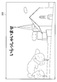
- FIG. 8 is an explanatory diagram illustrating an example of an image displayed on the display device that is the light source 131 of the information processing device 13, and FIG. 9 illustrates that the identification information acquisition unit 112 acquires the identification information from the image illustrated in FIG. It is explanatory drawing which showed the method.
- a plurality of selection buttons 210B and explanatory text 210C are displayed in the background area 210A. Yes.
- the background area 210A is an area having a uniform hue, for example.
- the selection button 210 ⁇ / b> B is an image representing a button for the user to select various transactions
- the explanatory note 210 ⁇ / b> C is a character image that describes an operation to be performed by the user in the display image 210.
- the background area 210 ⁇ / b> A preferably occupies most of the display image 210.
- the visible light communication control unit 132 can acquire identification information from the captured image by detecting a change in luminance of the display image 210 in the background region 210A having a uniform hue.
- the identification information acquisition unit 112 extracts the display image 211 of the light source 131 from the image captured by the imaging unit 111. Next, the identification information acquisition unit 112 detects a background area 211 ⁇ / b> A having a uniform hue from the display image 211. Here, the identification information acquisition unit 112 may detect the background region 211A by storing the hue of the background region 211A in advance. Further, the identification information acquisition unit 112 may regard the widest region of the same hue region in the display image 211 as the background region 211A.
- the identification information acquisition unit 112 integrates the pixel values of the pixels determined to be the background region 211A for each line to which the pixel belongs.
- the identification information acquisition unit 112 calculates the average value of the pixel values of all lines from the integrated value of the pixel values for each line, and the ratio of the integrated value of the pixel values of each line to the average value of the pixel values of all lines Is calculated. Further, the identification information acquisition unit 112 processes the ratio of the integrated values of the pixel values of each line by a shutter function based on the rolling shutter operation. Thereby, the identification information acquisition unit 112 can separate the encoded identification information from the display image 211. Furthermore, the identification information acquisition unit 112 can acquire the identification information of the information processing device 13 by decoding the encoded identification information.
- the integrated value i (y) obtained by integrating the pixels of the background area 211A for each line is s (t) for the shutter function, f (t) for the identification information, and i bg for the hue information for the background area 211A. Then, it can be expressed by the following formula 101.
- y is a line index
- t is time.
- the identification information second acquisition method in the identification information acquisition unit 112 has been specifically described.
- the identification information acquisition unit 112 is a case where the imaging frame rate of the imaging unit 111 is slower than the frequency for controlling the light emission state of the light source 131 by the visible light communication control unit 132. Identification information of the information processing apparatus 13 can be acquired.
- the third acquisition method is an identification information acquisition method in a case where the imaging unit 111 can capture images by a rolling shutter operation and can simultaneously capture the light source 131 with different exposure times.
- the identification information acquisition unit 112 acquires the identification information of the information processing device 13 even when the background area 210A cannot be detected from the display image 210 or the display image 210 is a moving image. can do.
- FIG. 10 is an explanatory diagram for explaining an operation when images are taken simultaneously at different exposure times in an imaging apparatus that performs a rolling shutter operation.
- the imaging apparatus when imaging one frame, the imaging apparatus performs a rolling shutter operation in which exposure is sequentially started for each line. However, each line is exposed with a different exposure time every other line. According to this configuration, although the resolution in the vertical direction is reduced, the imaging apparatus can simultaneously acquire images taken at different exposure times.
- the identification information acquisition unit 112 uses a plurality of images captured at different exposure times, so that even when the background area 210A cannot be detected from the display image 210 or when the display image 210 is a moving image, Identification information can be acquired.
- the method for controlling the exposure time of each pixel is not particularly limited as long as the imaging device can simultaneously image the light source 131 with different exposure times. That is, the imaging apparatus may control the exposure time for each line or the exposure time for each pixel in order to capture images with different exposure times.
- FIG. 11 is an explanatory diagram illustrating an example of an image displayed on the display device (that is, the light source 131) of the information processing device 13, and FIG. 12 illustrates the identification information acquisition unit 112 from the image illustrated in FIG. It is explanatory drawing which showed the method to acquire.
- the display image 220 displayed on the display device (that is, the light source 131) of the information processing device 13 is, for example, a landscape photograph image in which the background region cannot be specified.
- the identification information acquisition unit 112 can acquire identification information by using a plurality of display images 221A and 221B having different exposure times. Specifically, the identification information acquisition unit 112 extracts the display images 221A and 221B of the light source 131 from the image captured by the imaging unit 111.
- the display images 221A and 221B are images captured at different exposure times, the integration times of changes in the light emission state (for example, luminance) of the light source 131 are different, and images having different bright and dark horizontal stripes are formed. It has become.
- the integrated value i 1 (y) obtained by integrating the pixels of the display image 221A for each line and the integrated value i 2 (y) obtained by integrating the pixels of the display image 221B for each line are the same as in the second acquisition method.
- the shutter functions as s 1 (t) and s 2 (t)
- the identification information as f (t)
- the hue information i bg (y) of the original images of the display images 221A and 221B 201 and Formula 202.
- y represents the position of the display images 221A and 221B in the vertical direction
- t is time.
- i 1 (y) and i 2 (y) can be calculated from the display images 221A and 221B. Further, s 1 (t) and s 1 (t) are known shutter functions. Therefore, by erasing i bg (y) in Equation 201 and Equation 202, the identification information acquisition unit 112 can calculate the identification information f (t).
- the identification information acquisition unit 112 can separate the encoded identification information by the above method, the identification information of the information processing apparatus 13 can be acquired by decoding the encoded identification information.
- the length of the exposure time of any one of the imaging unit 111 is an integral multiple of the luminance change period of the light source 131
- the change in the light emission state of the light source 131 is integrated over the entire captured image. It becomes uniform. That is, since the captured display image is an image in which bright and dark horizontal stripes are not formed, i 1 (y) can be expressed by a simpler expression like Expression 203 below. Therefore, in such a case, the formula 202 can be transformed as the following formula 204.
- the mathematical formula 204 has the same format as the mathematical formula 102 in the second acquisition method in which the hue of the background region 211A is known. Therefore, the identification information acquisition unit 112 can more easily separate the encoded identification information from the display images 221A and 221B, as in the second acquisition method.
- i 1 (y) can be similarly expressed by Equation 203 above. Therefore, even in such a case, the identification information acquisition unit 112 can more easily separate the encoded identification information from the display images 221A and 221B.
- the identification information acquisition unit 112 can acquire the identification information of the information processing apparatus 13 even when the background area 210A cannot be detected from the display image 210 or when the display image 210 is a moving image. it can.
- FIG. 13 is a block diagram illustrating an example of a hardware configuration that configures the information processing apparatus 13 according to the present embodiment. That is, information processing by the information processing terminal 11 and the information processing apparatus 13 according to the present embodiment is realized by cooperation of software and hardware. Note that the hardware configuration of the information processing terminal 11 is substantially the same as that of the information processing apparatus 13, and thus the description thereof is omitted here.
- the information processing apparatus 13 includes a CPU (Central Processing Unit) 301, a ROM (Read Only Memory) 303, a RAM (Random Access Memory) 305, a bridge 309, internal buses 307 and 311, and the like. , An interface 313, an input device 315, an output device 317, a storage device 319, and a communication device 321.
- a CPU Central Processing Unit
- ROM Read Only Memory
- RAM Random Access Memory
- the CPU 301 functions as an arithmetic processing device and a control device, and controls the overall operation in the information processing device 13 according to various programs.
- the ROM 303 stores programs and calculation parameters used by the CPU 301, and the RAM 305 temporarily stores programs used in the execution of the CPU 301, parameters that change as appropriate during the execution, and the like.
- CPU301 performs functions, such as visible light communication control part 132 and transaction execution part 136, for example.
- the CPU 301 implements functions such as the identification information acquisition unit 112 and the display control unit 113.
- the CPU 301, ROM 303, and RAM 305 are connected to each other by a bridge 309, internal buses 307 and 311, and the like.
- the CPU 301, ROM 303, and RAM 305 are also connected to the input device 315, the output device 317, the storage device 319, and the communication device 321 via the interface 313.
- the input device 315 is a device for inputting information from the user or the outside.
- the input device 315 also includes an input control circuit for generating an input signal based on the input information and outputting it to the CPU 301.
- the input device 315 implements, for example, the imaging unit 111 and the input unit 116.
- the output device 317 includes, for example, a display device such as a liquid crystal display device and an organic EL display device, and an audio output device such as a speaker and headphones.
- the output device 317 implements functions such as the light source 131, for example.
- the storage device 319 is a data storage device configured as an example of a storage unit of the information processing device 13.
- the storage device 319 may include a storage medium, a storage device that stores data in the storage medium, a reading device that reads data from the storage medium, and a deletion device that deletes stored data.
- the storage device 319 implements functions such as the storage unit 133, for example.
- the storage device 319 implements functions such as the display storage unit 114, for example.
- the communication device 321 is a communication interface configured with, for example, a communication device for connecting to another device or the network 15.
- the communication device 321 may be a wireless LAN compatible communication device or a cable communication device that performs wired cable communication.
- the communication device 321 implements functions such as the input information receiving unit 134 and the communication unit 135, for example.
- the communication device 321 realizes functions such as the input information transmission unit 117, for example.
- the user can perform an input operation to the information processing apparatus 13 using the information processing terminal 11.
- the information processing system 1 uses visible light communication that dynamically changes and is not visually recognized for information transmission between the information processing terminal 11 and the information processing device 13, thereby preventing information skimming and improving security. be able to.
- the information processing system 1 information is transmitted by visible light communication using the change in the light emission state of the light source, so that the user can easily grasp the transmission source and the communication range. Therefore, the information processing system 1 can prevent the user from operating the information processing apparatus 13 that is not intended.
- the information processing system 1 can determine whether or not the information processing terminal 11 has left the information processing apparatus 13 by monitoring the communication state of visible light communication. Therefore, when the information processing terminal 11 leaves the information processing apparatus 13, the information processing system 1 stops the display of the input screen displayed on the information processing terminal 11, so that the information processing apparatus 13 can be moved from a remote position. Operation can be prevented.
- the visible light communication control unit that controls the light emission state of the light source and transmits the identification information
- An information processing apparatus comprising: Imaging unit, An identification information acquisition unit that performs image processing on an image of the light source captured by the imaging unit and acquires identification information of the information processing apparatus; A display control unit that controls display of an input screen on which an operation on the information processing apparatus is input based on the identification information; An input information transmitting unit for transmitting the input information input on the input screen to the information processing apparatus;
- An information processing terminal comprising: Information processing system including (2) The information processing system according to (1), wherein the visible light communication control unit transmits the identification information by changing luminance or hue of the light source.
- the visible light communication control unit controls a light emission state of the light source at a frequency higher than a frame rate of the imaging unit.
- the identification information acquisition unit extracts a background region having a predetermined luminance or hue from the image of the light source imaged by the imaging unit, and acquires the identification information based on a change in luminance or hue in the background region.
- the imaging unit simultaneously captures a plurality of images of the light source having different exposure times,
- the visible light communication control unit controls a light emission state of the light source at a frequency lower than a frame rate of the imaging unit;
- the identification information acquisition unit acquires the identification information of the information processing apparatus by performing image processing on an image captured at a predetermined timing by the imaging unit, When the identification information acquisition unit does not acquire the identification information of the information processing apparatus for a predetermined time, the display control unit stops displaying the input screen.
- (1) to (7) The information processing system according to any one of the above.
- the information processing apparatus is an automatic transaction apparatus, The information processing apparatus according to any one of (1) to (9), wherein the information processing apparatus executes a transaction based on the input information received from the information processing terminal and authentication information of a user of the information processing terminal. The information processing system described.
- An information processing apparatus comprising: (12) An imaging unit; An identification information acquisition unit that performs image processing on an image captured by the imaging unit and acquires identification information of the information processing device transmitted according to a light emission state of a light source of the information processing device; A display control unit that controls display of an input screen on which an operation on the information processing apparatus is input based on the identification information; An input information transmitting unit for transmitting the input information input on the input screen to the information processing apparatus;
- An information processing terminal comprising:
Abstract
Description
1.本開示の一実施形態に係る情報処理システム
1.1.情報処理システムの構成
1.2.情報処理端末、および情報処理装置の構成
1.3.情報処理システムの動作
2.識別情報の取得方法
2.1.第1の取得方法
2.2.第2の取得方法
2.3.第3の取得方法
3.本開示の一実施形態に係るハードウェアの構成
4.まとめ
まず、図1~図5を参照して、本開示の一実施形態に係る情報処理システムについて説明する。本実施形態に係る情報処理システムは、可視光通信によって送信された識別情報をユーザが所持する情報処理端末が受信することにより、情報処理装置への入力操作を情報処理端末にて行う情報処理システムである。
まず、図1を参照して、本開示の一実施形態に係る情報処理システム全体の概略構成について説明する。図1は、本実施形態に係る情報処理システムの全体構成を説明する説明図である。
次に、図2を参照して、本実施形態に係る情報処理端末11、および情報処理装置13の具体的な機能構成について説明する。図2は、本実施形態に係る情報処理端末11、および情報処理装置13の内部構成を説明するブロック図である。
撮像部111は、撮像レンズおよび撮像素子等を備え、被写体(より詳細には、光源131)の画像を取得する。具体的には、撮像部111は、CMOS(Complementary Metal-Oxide Semiconductor)イメージセンサ、またはCCD(Charge-Coupled Device)イメージセンサなどで構成される撮像素子により、撮像レンズを介して入射する被写体からの光を光電変換し、画像信号に変換する。
光源131は、発光状態の制御が可能な照明または表示装置であり、好ましくは表示装置である。また、光源131は、可視光通信制御部132により輝度または色相が制御される。したがって、光源131は、輝度または色相の時系列的な変化によって符号化された識別情報を情報処理端末11へ送信することができる。
次に、図4を参照して、本実施形態に係る情報処理システム1の動作の流れについて説明する。図4は、本実施形態に係る情報処理システム1の動作の流れを説明するフローチャート図である。
続いて、光源131の画像から識別情報取得部112が識別情報を取得する具体的な方法について説明する。光源131の画像から識別情報取得部112が識別情報を取得する方法は、撮像部111の撮像方式、および光源131(より詳細には、表示装置)の画像の種類によって、以下の第1~第3の取得方法が挙げられる。
まず、識別情報取得部112における識別情報の第1の取得方法について説明する。第1の取得方法は、撮像部111がグローバルシャッタ動作により光源131を撮像し、かつ、撮像部111の撮像のフレームレートが可視光通信制御部132による光源131の発光状態を制御する周波数よりも速い場合における識別情報の取得方法である。
次に、識別情報取得部112における識別情報の第2の取得方法について説明する。第2の取得方法は、撮像部111がローリングシャッタ動作により光源131を撮像する場合における識別情報の取得方法である。


続いて、識別情報取得部112における識別情報の第3の取得方法について説明する。第3の取得方法は、撮像部111がローリングシャッタ動作により撮像し、かつ異なる露光時間で同時に光源131を撮像することができる場合における識別情報の取得方法である。


続いて、図13を参照して、本実施形態に係る情報処理端末11および情報処理装置13のハードウェア構成について説明する。図13は、本実施形態に係る情報処理装置13を構成するハードウェア構成の一例を示したブロック図である。すなわち、本実施形態に係る情報処理端末11および情報処理装置13による情報処理は、ソフトウェアと、ハードウェアとの協働によって実現される。なお、情報処理端末11のハードウェア構成については、情報処理装置13と実質的に同様であるため、ここでの説明は省略する。
以上にて説明したように、本実施形態に係る情報処理システム1によれば、ユーザは、情報処理端末11を用いて情報処理装置13への入力操作を行うことができる。また、情報処理システム1は、情報処理端末11と情報処理装置13との情報伝達に、動的に変化し、視認されない可視光通信を用いるため、情報のスキミングを防止し、セキュリティ性を向上させることができる。
(1)
光源、
情報処理装置の識別情報に基づいて、前記光源の発光状態を制御し、前記識別情報を送信する可視光通信制御部、
を備える情報処理装置と、
撮像部、
前記撮像部により撮像された前記光源の画像を画像処理し、前記情報処理装置の識別情報を取得する識別情報取得部、
前記識別情報に基づいて、前記情報処理装置に対する操作が入力される入力画面の表示を制御する表示制御部、
前記入力画面に入力された入力情報を前記情報処理装置に送信する入力情報送信部、
を備える情報処理端末と、
を含む情報処理システム。
(2)
前記可視光通信制御部は、前記光源の輝度または色相を変化させることによって前記識別情報を送信する、前記(1)に記載の情報処理システム。
(3)
前記撮像部は、一部の画素ごとに順次撮像を行うローリングシャッタ動作により前記光源を撮像する、前記(1)または(2)に記載の情報処理システム。
(4)
前記可視光通信制御部は、前記撮像部のフレームレートよりも高い周波数で前記光源の発光状態を制御する、前記(3)に記載の情報処理システム。
(5)
前記識別情報取得部は、前記撮像部により撮像された前記光源の画像から所定の輝度または色相の背景領域を抽出し、前記背景領域における輝度または色相の変動に基づいて、前記識別情報を取得する、前記(4)に記載の情報処理システム。
(6)
前記撮像部は、露光時間の異なる前記光源の画像を複数同時に撮像し、
前記識別情報取得部は、撮像された前記光源の複数の画像に基づいて、前記識別情報を取得する、前記(4)に記載の情報処理システム。
(7)
前記可視光通信制御部は、前記撮像部のフレームレートよりも低い周波数で前記光源の発光状態を制御し、
前記撮像部は、全画素同時に撮像を行うグローバルシャッタ動作により前記光源を撮像する、前記(1)または(2)に記載の情報処理システム。
(8)
前記識別情報取得部は、前記撮像部により所定のタイミングで撮像された画像を画像処理することで前記情報処理装置の識別情報を取得し、
前記識別情報取得部により、所定時間の間、前記情報処理装置の識別情報が取得されなかった場合、前記表示制御部は、前記入力画面の表示を中止する、前記(1)~(7)のいずれか一項に記載の情報処理システム。
(9)
前記光源は、画像が表示される表示部である、前記(1)~(8)のいずれか一項に記載の情報処理システム。
(10)
前記情報処理装置は、自動取引装置であり、
前記情報処理装置は、前記情報処理端末から受信した前記入力情報、および前記情報処理端末のユーザの認証情報に基づいて取引を実行する、請前記(1)~(9)のいずれか一項に記載の情報処理システム。
(11)
光源と、
情報処理装置の識別情報に基づいて、前記光源の発光状態を制御し、前記識別情報を送信する可視光通信制御部と、
を備える情報処理装置。
(12)
撮像部と、
前記撮像部により撮像された画像を画像処理し、情報処理装置の光源の発光状態により伝達される前記情報処理装置の識別情報を取得する識別情報取得部と、
前記識別情報に基づいて、前記情報処理装置に対する操作が入力される入力画面の表示を制御する表示制御部と、
前記入力画面に入力された入力情報を前記情報処理装置に送信する入力情報送信部と、
を備える情報処理端末。
11 情報処理端末
13 情報処理装置
15 ネットワーク
17 金融機関サーバ
111 撮像部
112 識別情報取得部
113 表示制御部
114 表示記憶部
115 表示部
116 入力部
117 入力情報送信部
131 光源
132 可視光通信制御部
133 記憶部
134 入力情報受信部
135 通信部
136 取引実行部
Claims (12)
- 光源、
情報処理装置の識別情報に基づいて、前記光源の発光状態を制御し、前記識別情報を送信する可視光通信制御部、
を備える情報処理装置と、
撮像部、
前記撮像部により撮像された前記光源の画像を画像処理し、前記情報処理装置の識別情報を取得する識別情報取得部、
前記識別情報に基づいて、前記情報処理装置に対する操作が入力される入力画面の表示を制御する表示制御部、
前記入力画面に入力された入力情報を前記情報処理装置に送信する入力情報送信部、
を備える情報処理端末と、
を含む情報処理システム。 - 前記可視光通信制御部は、前記光源の輝度または色相を変化させることによって前記識別情報を送信する、請求項1に記載の情報処理システム。
- 前記撮像部は、一部の画素ごとに順次撮像を行うローリングシャッタ動作により前記光源を撮像する、請求項1に記載の情報処理システム。
- 前記可視光通信制御部は、前記撮像部のフレームレートよりも高い周波数で前記光源の発光状態を制御する、請求項3に記載の情報処理システム。
- 前記識別情報取得部は、前記撮像部により撮像された前記光源の画像から所定の輝度または色相の背景領域を抽出し、前記背景領域における輝度または色相の変動に基づいて、前記識別情報を取得する、請求項4に記載の情報処理システム。
- 前記撮像部は、露光時間の異なる前記光源の画像を複数同時に撮像し、
前記識別情報取得部は、撮像された前記光源の複数の画像に基づいて、前記識別情報を取得する、請求項4に記載の情報処理システム。 - 前記可視光通信制御部は、前記撮像部のフレームレートよりも低い周波数で前記光源の発光状態を制御し、
前記撮像部は、全画素同時に撮像を行うグローバルシャッタ動作により前記光源を撮像する、請求項1に記載の情報処理システム。 - 前記識別情報取得部は、前記撮像部により所定のタイミングで撮像された画像を画像処理することで前記情報処理装置の識別情報を取得し、
前記識別情報取得部により、所定時間の間、前記情報処理装置の識別情報が取得されなかった場合、前記表示制御部は、前記入力画面の表示を中止する、請求項1に記載の情報処理システム。 - 前記光源は、画像が表示される表示部である、請求項1に記載の情報処理システム。
- 前記情報処理装置は、自動取引装置であり、
前記情報処理装置は、前記情報処理端末から受信した前記入力情報、および前記情報処理端末のユーザの認証情報に基づいて取引を実行する、請求項1に記載の情報処理システム。 - 光源と、
情報処理装置の識別情報に基づいて、前記光源の発光状態を制御し、前記識別情報を送信する可視光通信制御部と、
を備える情報処理装置。 - 撮像部と、
前記撮像部により撮像された画像を画像処理し、情報処理装置の光源の発光状態により伝達される前記情報処理装置の識別情報を取得する識別情報取得部と、
前記識別情報に基づいて、前記情報処理装置に対する操作が入力される入力画面の表示を制御する表示制御部と、
前記入力画面に入力された入力情報を前記情報処理装置に送信する入力情報送信部と、
を備える情報処理端末。
Priority Applications (2)
| Application Number | Priority Date | Filing Date | Title |
|---|---|---|---|
| EP15850693.1A EP3208779B1 (en) | 2014-10-15 | 2015-08-07 | System and device for secured communication of identification information between two devices |
| US15/513,756 US10409968B2 (en) | 2014-10-15 | 2015-08-07 | Information processing system, information processing device, and information processing terminal |
Applications Claiming Priority (2)
| Application Number | Priority Date | Filing Date | Title |
|---|---|---|---|
| JP2014-210857 | 2014-10-15 | ||
| JP2014210857 | 2014-10-15 |
Publications (1)
| Publication Number | Publication Date |
|---|---|
| WO2016059860A1 true WO2016059860A1 (ja) | 2016-04-21 |
Family
ID=55746408
Family Applications (1)
| Application Number | Title | Priority Date | Filing Date |
|---|---|---|---|
| PCT/JP2015/072573 WO2016059860A1 (ja) | 2014-10-15 | 2015-08-07 | 情報処理システム、情報処理装置、および情報処理端末 |
Country Status (3)
| Country | Link |
|---|---|
| US (1) | US10409968B2 (ja) |
| EP (1) | EP3208779B1 (ja) |
| WO (1) | WO2016059860A1 (ja) |
Families Citing this family (3)
| Publication number | Priority date | Publication date | Assignee | Title |
|---|---|---|---|---|
| US10346675B1 (en) * | 2016-04-26 | 2019-07-09 | Massachusetts Mutual Life Insurance Company | Access control through multi-factor image authentication |
| US10354126B1 (en) * | 2016-04-26 | 2019-07-16 | Massachusetts Mutual Life Insurance Company | Access control through multi-factor image authentication |
| CN110472393A (zh) * | 2019-07-18 | 2019-11-19 | 平安科技(深圳)有限公司 | 基于生物识别的信息显示方法、装置、存储介质和设备 |
Citations (2)
| Publication number | Priority date | Publication date | Assignee | Title |
|---|---|---|---|---|
| JP2008269186A (ja) * | 2007-04-18 | 2008-11-06 | Oki Electric Ind Co Ltd | 自動取引装置 |
| WO2013175803A1 (ja) * | 2012-05-24 | 2013-11-28 | パナソニック株式会社 | 情報通信方法 |
Family Cites Families (9)
| Publication number | Priority date | Publication date | Assignee | Title |
|---|---|---|---|---|
| JP2007172004A (ja) | 2005-12-19 | 2007-07-05 | Hitachi Omron Terminal Solutions Corp | 自動機取引システム |
| JP4660398B2 (ja) | 2005-12-23 | 2011-03-30 | 株式会社東芝 | ユーザー認証システムと、このユーザー認証システムで使用される提供用サーバ装置、携帯通信装置、利用者用携帯通信装置、承認者用携帯通信装置および認証用サーバ装置と、これらの装置のためのプログラム |
| JP4992251B2 (ja) | 2006-03-06 | 2012-08-08 | 沖電気工業株式会社 | 自動取引システム |
| JP2008134733A (ja) | 2006-11-27 | 2008-06-12 | Hitachi Ltd | 金融処理情報管理システム、金融処理情報管理方法、および、金融処理情報管理プログラム |
| JP2009245272A (ja) | 2008-03-31 | 2009-10-22 | Promise Co Ltd | カードレス決済システム、カードレス決済方法、及び記録媒体 |
| JP5151931B2 (ja) * | 2008-11-26 | 2013-02-27 | 富士通株式会社 | 認証システム,認証装置,認証対象端末,認証方法,認証装置用プログラムおよび認証対象端末用プログラム |
| WO2012088512A2 (en) * | 2010-12-23 | 2012-06-28 | Paydiant, Inc. | Mobile phone atm processing methods and systems |
| US8988574B2 (en) * | 2012-12-27 | 2015-03-24 | Panasonic Intellectual Property Corporation Of America | Information communication method for obtaining information using bright line image |
| SG10201610410WA (en) * | 2012-12-27 | 2017-01-27 | Panasonic Ip Corp America | Information communication method |
-
2015
- 2015-08-07 WO PCT/JP2015/072573 patent/WO2016059860A1/ja active Application Filing
- 2015-08-07 EP EP15850693.1A patent/EP3208779B1/en active Active
- 2015-08-07 US US15/513,756 patent/US10409968B2/en active Active
Patent Citations (2)
| Publication number | Priority date | Publication date | Assignee | Title |
|---|---|---|---|---|
| JP2008269186A (ja) * | 2007-04-18 | 2008-11-06 | Oki Electric Ind Co Ltd | 自動取引装置 |
| WO2013175803A1 (ja) * | 2012-05-24 | 2013-11-28 | パナソニック株式会社 | 情報通信方法 |
Non-Patent Citations (1)
| Title |
|---|
| See also references of EP3208779A4 * |
Also Published As
| Publication number | Publication date |
|---|---|
| US10409968B2 (en) | 2019-09-10 |
| US20170293746A1 (en) | 2017-10-12 |
| EP3208779B1 (en) | 2022-05-04 |
| EP3208779A1 (en) | 2017-08-23 |
| EP3208779A4 (en) | 2018-06-06 |
Similar Documents
| Publication | Publication Date | Title |
|---|---|---|
| JP6360621B2 (ja) | 距離画像取得装置及び距離画像取得方法 | |
| JP5541153B2 (ja) | 通信システム、送信装置及び受信装置 | |
| CN108399349B (zh) | 图像识别方法及装置 | |
| CN105830367B (zh) | 可见光通信方法、识别信号及接收装置 | |
| WO2013077334A1 (ja) | 送信装置、受信装置及び方法 | |
| KR102392751B1 (ko) | 카메라 모듈을 구비한 전자 장치 및 전자 장치 제어 방법 | |
| KR101909082B1 (ko) | 사용자 인터랙션을 이용하여 이동 단말을 제어하는 장치 및 방법 | |
| JP2015115839A5 (ja) | ||
| WO2016059860A1 (ja) | 情報処理システム、情報処理装置、および情報処理端末 | |
| CN102484792A (zh) | 在移动通信终端中使用图像识别的无线连接方法和设备 | |
| CN111292504A (zh) | 一种通过图像识别进行安全告警方法及系统 | |
| CN108702833A (zh) | 包括发光装置的电子装置及其操作方法 | |
| CN113591517A (zh) | 一种活体检测方法及相关设备 | |
| CN106961546A (zh) | 信息处理装置和方法、摄像装置、显示装置、控制方法 | |
| JP6179227B2 (ja) | 情報処理装置、携帯端末および情報入力装置 | |
| EP3217644B1 (en) | Information processing device | |
| JP4932938B1 (ja) | 点呼システム | |
| WO2016147589A1 (ja) | 情報コード画像表示システム、情報コード画像表示端末、情報コード画像表示プログラム、サーバ及び情報コード画像生成プログラム | |
| US10211918B2 (en) | Device, system, and method for displaying an image together with a superimposed light component representing a code | |
| KR102574494B1 (ko) | Ar 글래스 시스템 및 이에 포함되는 사용자 단말기 및 그들의 제어방법 | |
| KR100960020B1 (ko) | 비전 네트워크 시스템 및 그 영상 서비스 방법 | |
| CN112470455B (zh) | 成像设备、电子装置及通知方法 | |
| JP6578742B2 (ja) | 業務システム | |
| JP6348252B2 (ja) | 情報端末装置および画面情報共有システム | |
| JP2016005258A (ja) | 撮影システム、撮影装置、情報処理方法、及びプログラム |
Legal Events
| Date | Code | Title | Description |
|---|---|---|---|
| 121 | Ep: the epo has been informed by wipo that ep was designated in this application |
Ref document number: 15850693 Country of ref document: EP Kind code of ref document: A1 |
|
| WWE | Wipo information: entry into national phase |
Ref document number: 15513756 Country of ref document: US |
|
| REEP | Request for entry into the european phase |
Ref document number: 2015850693 Country of ref document: EP |
|
| WWE | Wipo information: entry into national phase |
Ref document number: 2015850693 Country of ref document: EP |
|
| NENP | Non-entry into the national phase |
Ref country code: DE |
|
| NENP | Non-entry into the national phase |
Ref country code: JP |