WO2016056344A1 - ワーク供給装置及び工作機械 - Google Patents
ワーク供給装置及び工作機械 Download PDFInfo
- Publication number
- WO2016056344A1 WO2016056344A1 PCT/JP2015/075673 JP2015075673W WO2016056344A1 WO 2016056344 A1 WO2016056344 A1 WO 2016056344A1 JP 2015075673 W JP2015075673 W JP 2015075673W WO 2016056344 A1 WO2016056344 A1 WO 2016056344A1
- Authority
- WO
- WIPO (PCT)
- Prior art keywords
- workpiece
- cover member
- opening
- work
- supply device
- Prior art date
Links
Images

Classifications
-
- B—PERFORMING OPERATIONS; TRANSPORTING
- B23—MACHINE TOOLS; METAL-WORKING NOT OTHERWISE PROVIDED FOR
- B23Q—DETAILS, COMPONENTS, OR ACCESSORIES FOR MACHINE TOOLS, e.g. ARRANGEMENTS FOR COPYING OR CONTROLLING; MACHINE TOOLS IN GENERAL CHARACTERISED BY THE CONSTRUCTION OF PARTICULAR DETAILS OR COMPONENTS; COMBINATIONS OR ASSOCIATIONS OF METAL-WORKING MACHINES, NOT DIRECTED TO A PARTICULAR RESULT
- B23Q7/00—Arrangements for handling work specially combined with or arranged in, or specially adapted for use in connection with, machine tools, e.g. for conveying, loading, positioning, discharging, sorting
- B23Q7/04—Arrangements for handling work specially combined with or arranged in, or specially adapted for use in connection with, machine tools, e.g. for conveying, loading, positioning, discharging, sorting by means of grippers
-
- B—PERFORMING OPERATIONS; TRANSPORTING
- B23—MACHINE TOOLS; METAL-WORKING NOT OTHERWISE PROVIDED FOR
- B23Q—DETAILS, COMPONENTS, OR ACCESSORIES FOR MACHINE TOOLS, e.g. ARRANGEMENTS FOR COPYING OR CONTROLLING; MACHINE TOOLS IN GENERAL CHARACTERISED BY THE CONSTRUCTION OF PARTICULAR DETAILS OR COMPONENTS; COMBINATIONS OR ASSOCIATIONS OF METAL-WORKING MACHINES, NOT DIRECTED TO A PARTICULAR RESULT
- B23Q11/00—Accessories fitted to machine tools for keeping tools or parts of the machine in good working condition or for cooling work; Safety devices specially combined with or arranged in, or specially adapted for use in connection with, machine tools
- B23Q11/08—Protective coverings for parts of machine tools; Splash guards
-
- B—PERFORMING OPERATIONS; TRANSPORTING
- B23—MACHINE TOOLS; METAL-WORKING NOT OTHERWISE PROVIDED FOR
- B23Q—DETAILS, COMPONENTS, OR ACCESSORIES FOR MACHINE TOOLS, e.g. ARRANGEMENTS FOR COPYING OR CONTROLLING; MACHINE TOOLS IN GENERAL CHARACTERISED BY THE CONSTRUCTION OF PARTICULAR DETAILS OR COMPONENTS; COMBINATIONS OR ASSOCIATIONS OF METAL-WORKING MACHINES, NOT DIRECTED TO A PARTICULAR RESULT
- B23Q2707/00—Automatic supply or removal of metal workpieces
- B23Q2707/003—Automatic supply or removal of metal workpieces in a lathe
Definitions
- the present invention relates to a workpiece supply device that supplies a workpiece to a machine tool such as an automatic lathe and a machine tool including the workpiece supply device.
- a workpiece supply device that supplies a workpiece to a machining area for machining a workpiece (machining material) is known (for example, see Patent Document 1).
- a loader head holds a workpiece replenished outside the machining area, and the loader head moves from the opening provided in the body cover that covers the machining area to the machining area. It enters and delivers the workpiece to the spindle of the machine tool.
- the loader head moving means is provided with a shielding plate capable of closing the opening. While the loader head is positioned in the processing area, the shielding plate closes the opening. The shielding plate blocks the opening, thereby preventing the steam and mist of the cutting fluid filling the machining area from scattering from the opening to the outside of the machining area.
- the airframe cover is provided with a shutter for closing the opening so as to be freely opened and closed separately from the closing plate.
- the present invention has been made in view of the above circumstances, and during machining of a workpiece, the machining area is closed, and scattering of cutting fluid and the like from the machining area is suppressed. It is an object of the present invention to provide a workpiece supply device capable of supplying a workpiece to be processed next in a supply region.
- a workpiece supply apparatus includes a workpiece holding means for holding the workpiece to be supplied to a machine tool having a workpiece supply area and a machining area, and the workpiece holding means between the supply area and the machining area.
- Moving means, and the work holding means enters and exits between the two regions through an opening provided in a partition member that separates the replenishment region and the processing region.
- An urging means for urging the member in the closing direction of the opening, and the urging means holds the workpiece holding hand in a state where the workpiece is being processed in the processing region. So it can hold the workpiece in the supply region, the cover member, the partition member side pressing to be configured to occlude the opening in, and said.
- the machine tool according to the present invention is characterized by including the above-described workpiece supply device.
- a workpiece outside the machining area is closed while the machining area is closed in a sealed state during the machining of the workpiece, and scattering of cutting fluid or the like from the machining area to the replenishment area is suppressed. It is possible to provide a workpiece supply device having a simple configuration capable of supplying a workpiece to be processed next in the supply region. Further, by providing such a workpiece supply device, it is possible to provide a simpler and smaller machine tool in which scattering of cutting fluid or the like during workpiece machining is effectively suppressed.
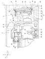
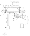
- FIG. 1 It is a perspective view showing the outline appearance of a machine tool provided with a work supply device concerning one embodiment of the present invention. It is an expansion perspective view which shows the principal part of the workpiece supply apparatus shown in FIG. It is a top view which shows the outline of the moving mechanism of the workpiece
- FIG. 1 is a perspective view showing a schematic appearance of an automatic lathe provided with the workpiece supply device of the present embodiment.
- the machine tool of this embodiment is coat
- the automatic lathe 100 has a spindle 10 disposed in the apparatus main body 1.
- the spindle 10 is provided with a chuck 11 for gripping the workpiece W.
- the spindle 10 is rotatably supported by the spindle stock 12.
- the direction along the principal axis C is the Z-axis direction
- the horizontal direction orthogonal to the Z-axis direction is the X-axis direction
- the vertical direction orthogonal to the Z-axis direction and the X-axis direction is the Y-axis direction.
- a tool post 14 (see FIG. 2) having a turret 13 for holding a tool is provided so as to be movable in the X, Y and Z axis directions.
- the apparatus main body 1 is provided with a processing chamber (processing region) 2 for processing the workpiece W, and adjacent to the processing chamber 2, a loader chamber (replenishment) provided with a workpiece supply device 30 for supplying the workpiece W to the spindle 10. Region) 3 is provided.
- the tip end side of the main shaft 10 is disposed in the processing chamber 2.
- a transport device 20 that transports the work W to the work supply device 30 is provided.
- the loader chamber 3 is an area where the workpiece supply device 30 receives and holds the workpiece W transferred by the transfer device 20.
- the processing chamber 2 is an area in which processing such as cutting is performed on the workpiece W gripped by the spindle 10 with the tool selected by the tool post 14.
- the cutting fluid is supplied in the vicinity of the machining point, so that the cutting fluid scatters in the machining chamber 2 and is filled with the cutting fluid vapor and mist.
- the loader chamber 3 and the processing chamber 2 are separated by a partition wall 4.
- the partition wall 4 is provided with an opening 5 through which the work holding portion (work holding means) 31 of the work supply device 30 enters and exits the loader chamber 3 and the processing chamber 2.
- the transfer device 20 includes a transfer conveyor device 21 and a delivery device 22.
- the delivery device 22 is disposed between the transfer conveyor device 21 and the workpiece supply device 30.
- the transfer conveyor device 21 transfers the workpiece W from the outside of the apparatus main body 1 into the loader chamber 3.
- the conveyor device 21 for conveyance is comprised from the belt conveyor 23 which mounts and conveys the workpiece
- the delivery device 22 delivers the workpiece W transferred into the loader chamber 3 by the transfer conveyor device 21 to the workpiece supply device 30.
- the delivery device 22 includes a pair of hands 25, a support base 26, a turning mechanism 27, and the like.
- the pair of hands 25 are provided on the support base 26 and are driven to be opened and closed by appropriate opening / closing means.
- the turning mechanism 27 turns the support base 26 together with the hand 25 between the transfer device 20 and the workpiece supply device 30.
- the pair of hands 25 are opened by the opening / closing means.
- the turning mechanism 27 turns the support base 26 in the direction of the conveyor device 21 so that both hands 25 are in a horizontal state.
- the workpiece W is inserted between both the horizontal and open hands 25.
- both hands 25 hold the workpiece W on the conveyor device 21 for conveyance.
- the turning mechanism 27 turns the support base 26 and turns 90 degrees in the direction of the workpiece supply device 30 so that both hands 25 are in the vertical state. Let With the above operation, the workpiece W can be arranged at a predetermined position (holding position) where the workpiece supply device 30 holds the workpiece W.
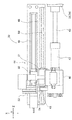
- the work supply device 30 includes a work holding unit 31, a moving mechanism (moving means) 32, and a cover member 33.
- the work holding unit 31 holds the work W.
- the moving mechanism (moving means) 32 moves the workpiece holding unit 31 to the holding position of the workpiece W and the delivery position to the spindle 10.
- the cover member 33 opens and closes the opening 5 of the partition wall 4.
- the work holding part 31 includes a base plate 34, an arm part 35, and a loader head 36.
- the arm portion 35 is fixed to the base plate 34.
- the loader head 36 is provided at one end of the arm portion 35.
- the loader head 36 is provided with a pair of hands 37 that can be freely opened and closed by appropriate opening and closing means. By inserting the workpiece W between the pair of open hands 37 and closing the hands 37 by the opening / closing means, the workpiece W can be held and held between the hands 37.
- the cover member 33 is disposed on the processing chamber 2 side and covers and closes the opening 5 from the inside of the processing chamber 2.
- the cover member 33 has an area larger than the opening area of the opening 5 and is formed so that the opening 5 can be hermetically and liquid-tightly sealed. It is also possible to provide a fitting flange on the opposing surfaces of the cover member 33 and the opening 5, or to arrange a seal member or the like. With this configuration, it is possible to improve the sealing property between the loader chamber 3 and the processing chamber 2 and the mutual connectivity.
- a plurality of shafts 38 are provided on the surface of the cover member 33 on the opening 5 side. Each shaft 38 protrudes in the direction of the loader chamber 3 and is provided in parallel with the Z-axis direction.
- flanges 41 are provided on both sides of the base plate 34.
- a collar 42 is integrally provided on the flange 41. The collar 42 is inserted through the shaft 38.
- the base plate 34 is connected to the cover member 33 so as to be relatively movable.
- a receiver 39 is mounted on the outer periphery near the tip of the shaft 38.
- a coil spring 40 as an urging means is mounted between the receiver 39 and the base plate 34. The coil spring 40 is fitted on the shaft 38. As shown in FIG. 4, the work holding portion 31 is pressed and biased to a position close to the cover member 33 by the coil spring 40 so that the collar 42 is normally pressed against the cover member 33.
- the moving mechanism 32 includes a shaft 43, a slide mechanism 44, and a rotating mechanism 45 as shown in FIG. 3A.
- the shaft 43 is disposed in parallel with the Z-axis direction.
- the slide mechanism 44 moves the shaft 43 back and forth in the Z-axis direction.
- the rotation mechanism 45 rotates the shaft 43.
- a base plate 34 is integrally fixed to one end of the shaft 43.
- the other end side of the shaft 43 is inserted into a sleeve 47 that is integrally fixed to the bracket 46.
- the shaft 43 is rotatably supported on the bracket 46 side.
- the slide mechanism 44 includes a linear guide 48 and a slide actuator 49.
- the linear guide 48 is installed in parallel with the Z axis direction and in parallel with the shaft 43.
- the linear guide 48 is provided with a slide rail 50 extending in the Z-axis direction.
- a bracket 46 is slidably supported on the slide rail 50 via a slider 51.
- the bracket 46 is integrally fixed to a slider 52 provided on the slide actuator 49.
- the rotation mechanism 45 includes a cylinder 53 that is integrally attached to the bracket 46.
- a cylinder shaft 54 of the cylinder 53 is connected to the shaft 43.
- the slide actuator 49 is driven, and the slider 52 is driven to move in the Z-axis direction.
- the shaft 43 integrally with the bracket 46 is guided by the linear guide 48 and moves in the Z-axis direction.
- the shaft 53 can be rotated around the axis line by driving the cylinder 53 and driving the cylinder shaft 54 forward and backward.
- the work holding unit 31 passes through the opening 5 and enters and exits the processing chamber 2 and the loader chamber 3.
- the cover member 33 moves forward and backward only in the processing chamber 2 and does not move to the loader chamber 3 side.
- the cover member 33 hits the partition wall 4 and stops moving. After this stop, by further operating the slide mechanism 44, the workpiece holding part 31 can be moved along the Z axis in the direction of the holding position of the workpiece W against the urging force of the coil spring 40.
- the work holding unit 31 can be freely moved to a position where the hand 37 can easily hold the work W.
- the length of the workpiece W in the axial direction varies due to a manufacturing error or the like, or there are cases where a plurality of types of workpieces W having different lengths are processed.
- the workpiece W can be easily held by the hand 37 by moving the workpiece holding portion 31 to a position where the workpiece 37 can be easily held according to the length of the workpiece W or the like. Become.
- the work holding unit 31 can be rotated around the axis of the shaft 43 together with the cover member 33.
- the rotation of the work holding unit 31 enables the cover member 33 and the work holding unit 31 to be integrally swung at a position where the work W held by the hand 37 faces the main shaft 10 in the processing chamber 2.
- the cover member 33 and the work holding part 31 are integrally formed at a position where the work holding part 31 can pass through the opening 5 and the loader head 36 faces the work W held by the delivery device 22 in the loader chamber 3. It can be swung.
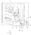
- the apparatus main body 1 is provided with a discharge device 60 for discharging the processed workpiece W out of the apparatus main body 1.
- the discharge device 60 includes a basket-shaped work receiving portion 61 and a discharge conveyor device 62.
- the work receiving unit 61 receives the work W discharged from the spindle 10.
- the work receiving portion 61 is pivotally supported on the partition wall 4 side so as to be rotatable about an axis parallel to the Z axis.
- the discharge conveyor device 62 transports the workpiece W delivered from the workpiece receiver 61 to the outside.
- the discharge conveyor device 62 includes a belt conveyor 63, a hood 64, and a drive mechanism 65.
- the hood 64 partially covers the belt conveyor 63.
- the drive mechanism 65 drives the belt conveyor 63 to rotate.
- the workpiece receiving portion 61 swings in the direction of the spindle 10 and stands by below the workpiece W held on the spindle 10 as shown by the solid line in FIG. 3B.
- the chuck 11 of the spindle 10 opens.
- An ejector device or the like provided in the main shaft 10 operates to push the work W from the main shaft 10, so that the work W falls into the work receiving portion 61.
- the workpiece receiving portion 61 swings in the direction of the hood 64 with the shaft support portion as a rotation axis, as shown by a two-dot chain line in FIG. 3B.
- the workpiece W is loaded into the hood 64 from the loading port 66 opened to the hood 64 by the swinging of the workpiece receiving portion 61.
- the workpiece W put into the hood 64 is transferred to the outside of the apparatus main body 1 by the belt conveyor 63 and is discharged to the workpiece collecting unit and the like.
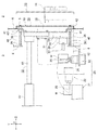
- FIG. 4 shows a state where the opening 5 is covered and closed by the cover member 33 of the workpiece supply device 30.
- the tip of the shaft 38 abuts against the stopper 6.
- the cover member 33 abuts against the partition wall 4 and stops moving, and is positioned with the opening 5 closed.
- the work holding part 31 is disposed in the loader chamber 3 in a state where the work holding part 31 is pressed and biased toward the cover member 33 by the coil spring 40.
- the cover member 33 is positioned so as to be in close contact with the partition wall 4 and closes the opening 5. Therefore, the force for bringing the cover member 33 into close contact with the partition wall 4 can be received on the shaft 38 side in addition to the contact portion of the cover member 33 with the partition wall 4.
- the hermeticity between the loader chamber 3 and the processing chamber 2 is maintained without applying an excessive load on the cover member 33 side.
- the workpiece W gripped by the spindle 10 can be processed in the processing chamber 2 with the opening 5 closed by the cover member 33. Therefore, it is possible to prevent the cutting fluid or the like from scattering from the processing chamber 2 into the loader chamber 3 during processing.
- the workpiece W can be transferred by the transfer conveyor device 21 of the transfer device 20 in the loader chamber 3 during the processing of the workpiece W in the processing chamber 2.
- the transferred work W can be placed at the holding position by the delivery device 22 of the transfer device 20.
- the work supply device 30 drives the slide mechanism 44 (see FIG. 3A) of the moving mechanism 32 in order to receive the work W from the delivery device 22.
- the slide mechanism 44 By driving the slide mechanism 44, the work holding portion 31 is moved in the direction of the work W against the urging force of the coil spring 40.
- FIG. 5 when the workpiece W is inserted between the pair of opened hands 37, the movement of the workpiece holding unit 31 is stopped. By closing both hands 37, the work W is held by both hands 37.
- the hands 25 are opened on the delivery device 22 side, the workpiece W is delivered from the delivery device 22 to the workpiece holding unit 31.
- the work holding unit 31 is moved in the direction of the cover member 33 while the work W is held by the pair of hands 37 by the slide mechanism 44. Since the work holding part 31 is moved in the direction of the work W in the loader chamber 3, the coil spring 40 is in a contracted state.
- the shaft 38 is pressed and biased toward the stopper 6 via the receiver 39 by the pressing biasing force of the coil spring 40 in the contracted state.
- the cover member 33 itself is also urged in the direction to close the opening 5, and the cover member 33 is not detached from the opening 5, and the closed state of the opening 5 is maintained. Therefore, the airtightness between the loader chamber 3 and the processing chamber 2 is maintained, and scattering of cutting fluid and the like from the processing chamber 2 side is prevented in the loader chamber 3.
- the work W can be supplied from the transfer device 20 to the work holding unit 31.
- the workpiece supply device 30 When the workpiece W is processed and discharged in the processing chamber 2, the workpiece supply device 30 performs an operation of delivering the workpiece W held by the hand 37 of the workpiece holding unit 31 to the spindle 10.
- the workpiece supply device 30 drives the slide mechanism 44 to move the workpiece holding unit 31 in the direction of the machining chamber 2 while holding the workpiece W.
- the cover member 33 moves away from the opening 5 and moves integrally with the work holding part 31 in the inner direction of the processing chamber 2.
- the work holding unit 31 enters the machining chamber 2 through the opened opening 5.
- the movement of the work holding unit 31 is stopped by the slide mechanism 44 in a state where the work W is arranged in front of the main shaft 10.
- the work holding unit 31 is swung together with the shaft 43 by the rotation mechanism 45 (see FIG. 3A).
- the loader head 36 can be arranged so that the workpiece W faces the main shaft 10.
- the work holding unit 31 is moved in the direction of the main spindle 10 in the Z-axis direction by the slide mechanism 44, and the work W is inserted into the chuck 11 in the open state.
- the chuck 11 of the main shaft 10 is closed, the pair of hands 37 of the work holding unit 31 are opened, and the work W is delivered to the main shaft 10.
- the work holding part 31 is moved in the direction away from the main shaft 10 in the Z-axis direction.
- the work holding part 31 is swung together with the shaft 43 in the direction opposite to the previous rotation direction, and the work holding part 31 is positioned in a posture capable of passing through the opening 5.
- the supply of the workpiece W from the workpiece supply device 30 to the spindle 10 is completed.
- the workpiece supply device 30 moves the workpiece holding unit 31 from the opening 5 into the loader chamber 3 by the slide mechanism 44. Due to the movement of the work holding portion 31, the opening 5 is closed by the cover member 33 as shown in FIG.
- the workpiece W held by the spindle 10 is processed by the tool of the tool post 14.
- the opening 5 is closed by the cover member 33 and the hermeticity between the loader chamber 3 and the processing chamber 2 is maintained. Therefore, it can prevent that the cutting fluid at the time of a process, its vapor
- the workpiece W is processed in the processing chamber 2, and the workpiece W to be next transferred to the spindle 10 is held in advance in the loader chamber 3 by the workpiece holding unit 31. it can. Therefore, the workpiece W can be delivered to the spindle 10 more quickly after the machining is completed.
- the loader chamber 3 and the processing chamber 2 can be closed in a sealed state during processing of the workpiece W. Therefore, scattering of cutting fluid or the like from the processing chamber 2 to the loader chamber 3 during workpiece processing can be prevented. Moreover, the sealing of the opening 5 can be secured by the cover member 33. For this reason, it is not necessary to provide a shutter for closing the opening 5 during the processing of the workpiece W and its driving means as in the prior art. It is not necessary to provide a space for the shutter and its driving means. Therefore, the number of parts and assembly man-hours can be reduced, and the workpiece supply device 30 and the automatic lathe 100 can be simplified and downsized. Further, the workpiece holding unit 31 can hold the workpiece W in parallel with the machining of the workpiece W. Therefore, it is possible to shorten the time related to the operation of supplying the workpiece W to the spindle 10 and improve the work supply efficiency.
- the work holding portion 31 is connected to the cover member 33 so as to be able to move forward and backward. Therefore, the workpiece W can be held even when the length of the workpiece W in the axial direction varies, or when a plurality of types of workpieces W having different lengths are processed.
- the cover member 33 is pressed and biased in the direction of closing the opening 5 by the pressing biasing force of the coil spring 40. Therefore, even if the work holding portion 31 moves forward and backward, the cover member 33 does not unexpectedly leave the opening 5 and the closed state of the opening 5 can be maintained. Further, the cover member 33 is arranged on the processing chamber 2 side and covers and closes the opening 5 from the inside of the processing chamber 2. Therefore, the cover member 33 moves only in the processing chamber 2 and does not move to the loader chamber 3 side. Therefore, it is possible to suppress the cutting fluid or the like adhering to the cover member 33 from falling into the loader chamber 3.
- a pressing urging means other than the coil spring 40 such as a plate spring or a torsion spring can be used. It is only necessary that the cover member 33 can be urged so that the closing of the opening 5 is not released even if the work holding portion 31 moves forward and backward.
- an urging means such as a tension spring (tensile spring) can be provided between the base plate 34 and the cover member 33.
- the cover member 33 can also be configured to be biased in the closing direction of the opening 5 by the pulling force of the tension spring.
Abstract
Description
本出願は、2014年10月7日に日本国特許庁に出願された特願2014-206538に基づいて優先権を主張し、その全ての開示は完全に本明細書で参照により組み込まれる。
Claims (4)
- ワークの補給領域及び加工領域を有する工作機械に対して供給する前記ワークを保持するワーク保持手段と、前記ワーク保持手段を前記補給領域と前記加工領域との間で移動させる移動手段とを備え、
前記ワーク保持手段が、前記補給領域と前記加工領域とを隔てる仕切り部材に設けられた開口部を通って前記両領域間を出入りして、前記工作機械との間で前記ワークの受け渡しを行うワーク供給装置において、
前記ワーク保持手段と一体的に移動し、該ワーク保持手段が前記補給領域内に移動したときに前記開口部を閉塞するカバー部材と、
前記カバー部材を前記開口部の閉塞方向に付勢する付勢手段とを備え、
該付勢手段が、前記加工領域で前記ワークの加工が行われている状態で、前記ワーク保持手段が前記補給領域で前記ワークを保持することができるように、前記カバー部材を、前記仕切り部材側に押圧して前記開口部を閉塞させるように構成されたこと、を特徴とするワーク供給装置。 - 前記ワーク保持手段は、前記カバー部材に対して相対的に進退動可能に該カバー部材に連結されるとともに、前記付勢手段により前記カバー部材と近接する方向に付勢され、
前記カバー部材が前記開口部を閉塞した状態で、前記ワーク保持手段が前記付勢手段の付勢力に抗して前記補給領域内を移動し、該補給領域に配置された前記ワークを保持することを特徴とする請求項1に記載のワーク供給装置。 - 前記カバー部材が、前記加工領域内に配置されるとともに前記開口部の開口面積よりも大きな面積で形成され、前記カバー部材が前記加工領域の内部側から前記開口部を被覆して閉塞することを特徴とする請求項2に記載のワーク供給装置。
- 請求項1から3のいずれか一項に記載のワーク供給装置を備えたことを特徴とする工作機械。
Priority Applications (5)
| Application Number | Priority Date | Filing Date | Title |
|---|---|---|---|
| ES15849385T ES2885534T3 (es) | 2014-10-07 | 2015-09-10 | Dispositivo de suministro de piezas de trabajo y máquina herramienta |
| KR1020177008868A KR101880006B1 (ko) | 2014-10-07 | 2015-09-10 | 워크 공급 장치 및 공작 기계 |
| US15/516,882 US9993903B2 (en) | 2014-10-07 | 2015-09-10 | Workpiece supply device and machine tool |
| CN201580056171.9A CN107073668B (zh) | 2014-10-07 | 2015-09-10 | 工件供给装置及机床 |
| EP15849385.8A EP3205447B1 (en) | 2014-10-07 | 2015-09-10 | Workpiece supply device and machine tool |
Applications Claiming Priority (2)
| Application Number | Priority Date | Filing Date | Title |
|---|---|---|---|
| JP2014-206538 | 2014-10-07 | ||
| JP2014206538A JP6351475B2 (ja) | 2014-10-07 | 2014-10-07 | ワーク供給装置及び工作機械 |
Publications (1)
| Publication Number | Publication Date |
|---|---|
| WO2016056344A1 true WO2016056344A1 (ja) | 2016-04-14 |
Family
ID=55652967
Family Applications (1)
| Application Number | Title | Priority Date | Filing Date |
|---|---|---|---|
| PCT/JP2015/075673 WO2016056344A1 (ja) | 2014-10-07 | 2015-09-10 | ワーク供給装置及び工作機械 |
Country Status (8)
| Country | Link |
|---|---|
| US (1) | US9993903B2 (ja) |
| EP (1) | EP3205447B1 (ja) |
| JP (1) | JP6351475B2 (ja) |
| KR (1) | KR101880006B1 (ja) |
| CN (1) | CN107073668B (ja) |
| ES (1) | ES2885534T3 (ja) |
| TW (1) | TWI641446B (ja) |
| WO (1) | WO2016056344A1 (ja) |
Cited By (1)
| Publication number | Priority date | Publication date | Assignee | Title |
|---|---|---|---|---|
| US20190143466A1 (en) * | 2017-11-14 | 2019-05-16 | Jtekt Corporation | Workpiece replacing apparatus and machine tool |
Families Citing this family (10)
| Publication number | Priority date | Publication date | Assignee | Title |
|---|---|---|---|---|
| JP6525933B2 (ja) * | 2016-10-11 | 2019-06-05 | ファナック株式会社 | 工作機械 |
| JP6438445B2 (ja) | 2016-10-11 | 2018-12-12 | ファナック株式会社 | 工作機械 |
| JP6481067B1 (ja) * | 2018-05-16 | 2019-03-13 | 株式会社滝澤鉄工所 | ワーク搬送機構付き工作機械 |
| CN109093736A (zh) * | 2018-07-19 | 2018-12-28 | 宁波夏亿机电科技有限公司 | 一种数控自动割胶片装置 |
| CN108788753A (zh) * | 2018-07-24 | 2018-11-13 | 荆门优德科技有限公司 | 一种用于es8左底架的磨削和锯切专用工作站 |
| CN108673156A (zh) * | 2018-07-24 | 2018-10-19 | 荆门优德科技有限公司 | 一种用于es8右底架的磨削和锯切专用工作站 |
| CN108673157A (zh) * | 2018-07-24 | 2018-10-19 | 荆门优德科技有限公司 | 一种用于kc-2底架的磨削和锯切专用工作站 |
| CN108788754A (zh) * | 2018-07-24 | 2018-11-13 | 荆门优德科技有限公司 | 一种用于铝合金工件的磨削和锯切专用工作站 |
| JP7122221B2 (ja) * | 2018-10-26 | 2022-08-19 | オークマ株式会社 | 工作機械 |
| CN117139657B (zh) * | 2023-11-01 | 2023-12-26 | 南通新思迪机电有限公司 | 一种具有自动上下料功能的快速车床 |
Citations (6)
| Publication number | Priority date | Publication date | Assignee | Title |
|---|---|---|---|---|
| JPH03109704U (ja) * | 1990-02-22 | 1991-11-11 | ||
| US5669751A (en) * | 1994-05-09 | 1997-09-23 | Cincinnati Milacron Inc. | Transport system for workpieces |
| JPH1199402A (ja) * | 1997-09-30 | 1999-04-13 | Murata Mach Ltd | ワーク払い出し装置 |
| JP2000061704A (ja) * | 1998-08-24 | 2000-02-29 | Mori Seiki Co Ltd | 工作機械のワーク搬出装置 |
| JP2005161420A (ja) * | 2003-11-28 | 2005-06-23 | Nakamura Tome Precision Ind Co Ltd | 旋盤のワーク排出装置 |
| JP2014054676A (ja) * | 2012-09-11 | 2014-03-27 | Murata Mach Ltd | ローダ装置 |
Family Cites Families (5)
| Publication number | Priority date | Publication date | Assignee | Title |
|---|---|---|---|---|
| TW375066U (en) * | 1997-10-03 | 1999-11-21 | zhi-xun Lin | Improved structure for the material clamp of the automatic lathe feeder |
| DE102005058347B4 (de) * | 2005-12-06 | 2014-10-23 | Schwäbische Werkzeugmaschinen GmbH | Werkzeugmaschine zur Bearbeitung von Werkstücken |
| KR100779805B1 (ko) * | 2006-12-14 | 2007-11-27 | 두산인프라코어 주식회사 | 공구 매거진 구동과 연계된 atc 도어의 개폐장치 |
| CN102089102B (zh) | 2008-07-10 | 2013-05-08 | 西铁城精机宫野股份有限公司 | 工件加工装置及工件加工方法 |
| TWM402161U (en) * | 2010-10-15 | 2011-04-21 | Tongtai Machine & Tool Co Ltd | Lathe reversing feeding system and automatic lathe with the same |
-
2014
- 2014-10-07 JP JP2014206538A patent/JP6351475B2/ja active Active
-
2015
- 2015-09-10 US US15/516,882 patent/US9993903B2/en active Active
- 2015-09-10 ES ES15849385T patent/ES2885534T3/es active Active
- 2015-09-10 EP EP15849385.8A patent/EP3205447B1/en active Active
- 2015-09-10 CN CN201580056171.9A patent/CN107073668B/zh active Active
- 2015-09-10 KR KR1020177008868A patent/KR101880006B1/ko active IP Right Grant
- 2015-09-10 WO PCT/JP2015/075673 patent/WO2016056344A1/ja active Application Filing
- 2015-09-24 TW TW104131635A patent/TWI641446B/zh active
Patent Citations (6)
| Publication number | Priority date | Publication date | Assignee | Title |
|---|---|---|---|---|
| JPH03109704U (ja) * | 1990-02-22 | 1991-11-11 | ||
| US5669751A (en) * | 1994-05-09 | 1997-09-23 | Cincinnati Milacron Inc. | Transport system for workpieces |
| JPH1199402A (ja) * | 1997-09-30 | 1999-04-13 | Murata Mach Ltd | ワーク払い出し装置 |
| JP2000061704A (ja) * | 1998-08-24 | 2000-02-29 | Mori Seiki Co Ltd | 工作機械のワーク搬出装置 |
| JP2005161420A (ja) * | 2003-11-28 | 2005-06-23 | Nakamura Tome Precision Ind Co Ltd | 旋盤のワーク排出装置 |
| JP2014054676A (ja) * | 2012-09-11 | 2014-03-27 | Murata Mach Ltd | ローダ装置 |
Non-Patent Citations (1)
| Title |
|---|
| See also references of EP3205447A4 * |
Cited By (2)
| Publication number | Priority date | Publication date | Assignee | Title |
|---|---|---|---|---|
| US20190143466A1 (en) * | 2017-11-14 | 2019-05-16 | Jtekt Corporation | Workpiece replacing apparatus and machine tool |
| US11141827B2 (en) * | 2017-11-14 | 2021-10-12 | Jtekt Corporation | Workpiece replacing apparatus and machine tool |
Also Published As
| Publication number | Publication date |
|---|---|
| EP3205447B1 (en) | 2021-07-07 |
| EP3205447A4 (en) | 2018-08-01 |
| ES2885534T3 (es) | 2021-12-14 |
| US9993903B2 (en) | 2018-06-12 |
| TW201618887A (zh) | 2016-06-01 |
| EP3205447A1 (en) | 2017-08-16 |
| TWI641446B (zh) | 2018-11-21 |
| CN107073668A (zh) | 2017-08-18 |
| CN107073668B (zh) | 2019-05-10 |
| KR101880006B1 (ko) | 2018-07-18 |
| JP2016074062A (ja) | 2016-05-12 |
| JP6351475B2 (ja) | 2018-07-04 |
| KR20170046178A (ko) | 2017-04-28 |
| US20170312873A1 (en) | 2017-11-02 |
Similar Documents
| Publication | Publication Date | Title |
|---|---|---|
| WO2016056344A1 (ja) | ワーク供給装置及び工作機械 | |
| JP7122221B2 (ja) | 工作機械 | |
| JPWO2016059738A1 (ja) | 横型工作機械 | |
| JP2013059826A (ja) | ワーク把持具及び旋盤のワークハンドリング方法 | |
| CN108568706B (zh) | 机床 | |
| US10752453B2 (en) | Joining apparatus, loading station, supply arrangement and method for loading a magazine | |
| JP6411852B2 (ja) | 搬送装置、搬送システム及び搬送方法 | |
| EP3127638A1 (en) | Tool mounting portion, tool holder for machine tool provided with said tool mounting portion, and machine tool | |
| JP2018062025A (ja) | ローディング装置及び加工装置 | |
| WO2015141298A1 (ja) | ワーク搬送装置、工作機械、及びワーク搬送方法 | |
| JP2009160672A (ja) | マニピュレータ | |
| JP6735354B2 (ja) | 工作機械および加工機械ライン | |
| JPWO2015145577A1 (ja) | 回転機能付き油圧クランプ装置 | |
| JP4303810B2 (ja) | 旋盤のワーク排出装置 | |
| JP2020078847A (ja) | ローディング装置及びそれを機内に備えた工作機械 | |
| JP6506627B2 (ja) | ワークの案内装置 | |
| KR20200043363A (ko) | 반송 장치 및 반송 방법 | |
| JP5125129B2 (ja) | ワーク給排装置 | |
| JP6700001B2 (ja) | 工作機械のワーク搬送装置 | |
| JP2005161420A (ja) | 旋盤のワーク排出装置 | |
| JP3659698B2 (ja) | ワーク搬送装置とそれを用いた工作機械 | |
| TWI632022B (zh) | Processing system and method for processing short-sized rod-shaped workpiece by using processing system | |
| US11059167B2 (en) | Multi-joint robot arm | |
| WO2020110184A1 (ja) | ワーク把持判定システム | |
| WO2020049730A1 (ja) | 工作機械 |
Legal Events
| Date | Code | Title | Description |
|---|---|---|---|
| 121 | Ep: the epo has been informed by wipo that ep was designated in this application |
Ref document number: 15849385 Country of ref document: EP Kind code of ref document: A1 |
|
| ENP | Entry into the national phase |
Ref document number: 20177008868 Country of ref document: KR Kind code of ref document: A |
|
| WWE | Wipo information: entry into national phase |
Ref document number: 15516882 Country of ref document: US |
|
| NENP | Non-entry into the national phase |
Ref country code: DE |
|
| REEP | Request for entry into the european phase |
Ref document number: 2015849385 Country of ref document: EP |