WO2016051824A1 - 濾過装置 - Google Patents
濾過装置 Download PDFInfo
- Publication number
- WO2016051824A1 WO2016051824A1 PCT/JP2015/059172 JP2015059172W WO2016051824A1 WO 2016051824 A1 WO2016051824 A1 WO 2016051824A1 JP 2015059172 W JP2015059172 W JP 2015059172W WO 2016051824 A1 WO2016051824 A1 WO 2016051824A1
- Authority
- WO
- WIPO (PCT)
- Prior art keywords
- backwash
- fluid
- filter element
- filtration device
- filter medium
- Prior art date
- Legal status (The legal status is an assumption and is not a legal conclusion. Google has not performed a legal analysis and makes no representation as to the accuracy of the status listed.)
- Ceased
Links
Images


Classifications
-
- B—PERFORMING OPERATIONS; TRANSPORTING
- B01—PHYSICAL OR CHEMICAL PROCESSES OR APPARATUS IN GENERAL
- B01D—SEPARATION
- B01D29/00—Filters with filtering elements stationary during filtration, e.g. pressure or suction filters, not covered by groups B01D24/00 - B01D27/00; Filtering elements therefor
- B01D29/11—Filters with filtering elements stationary during filtration, e.g. pressure or suction filters, not covered by groups B01D24/00 - B01D27/00; Filtering elements therefor with bag, cage, hose, tube, sleeve or like filtering elements
- B01D29/13—Supported filter elements
- B01D29/23—Supported filter elements arranged for outward flow filtration
-
- B—PERFORMING OPERATIONS; TRANSPORTING
- B01—PHYSICAL OR CHEMICAL PROCESSES OR APPARATUS IN GENERAL
- B01D—SEPARATION
- B01D29/00—Filters with filtering elements stationary during filtration, e.g. pressure or suction filters, not covered by groups B01D24/00 - B01D27/00; Filtering elements therefor
- B01D29/11—Filters with filtering elements stationary during filtration, e.g. pressure or suction filters, not covered by groups B01D24/00 - B01D27/00; Filtering elements therefor with bag, cage, hose, tube, sleeve or like filtering elements
- B01D29/117—Filters with filtering elements stationary during filtration, e.g. pressure or suction filters, not covered by groups B01D24/00 - B01D27/00; Filtering elements therefor with bag, cage, hose, tube, sleeve or like filtering elements arranged for outward flow filtration
-
- B—PERFORMING OPERATIONS; TRANSPORTING
- B01—PHYSICAL OR CHEMICAL PROCESSES OR APPARATUS IN GENERAL
- B01D—SEPARATION
- B01D29/00—Filters with filtering elements stationary during filtration, e.g. pressure or suction filters, not covered by groups B01D24/00 - B01D27/00; Filtering elements therefor
- B01D29/50—Filters with filtering elements stationary during filtration, e.g. pressure or suction filters, not covered by groups B01D24/00 - B01D27/00; Filtering elements therefor with multiple filtering elements, characterised by their mutual disposition
- B01D29/52—Filters with filtering elements stationary during filtration, e.g. pressure or suction filters, not covered by groups B01D24/00 - B01D27/00; Filtering elements therefor with multiple filtering elements, characterised by their mutual disposition in parallel connection
-
- B—PERFORMING OPERATIONS; TRANSPORTING
- B01—PHYSICAL OR CHEMICAL PROCESSES OR APPARATUS IN GENERAL
- B01D—SEPARATION
- B01D29/00—Filters with filtering elements stationary during filtration, e.g. pressure or suction filters, not covered by groups B01D24/00 - B01D27/00; Filtering elements therefor
- B01D29/62—Regenerating the filter material in the filter
- B01D29/64—Regenerating the filter material in the filter by scrapers, brushes, nozzles, or the like, acting on the cake side of the filtering element
- B01D29/6407—Regenerating the filter material in the filter by scrapers, brushes, nozzles, or the like, acting on the cake side of the filtering element brushes
- B01D29/6423—Regenerating the filter material in the filter by scrapers, brushes, nozzles, or the like, acting on the cake side of the filtering element brushes with a translational movement with respect to the filtering element
-
- B—PERFORMING OPERATIONS; TRANSPORTING
- B01—PHYSICAL OR CHEMICAL PROCESSES OR APPARATUS IN GENERAL
- B01D—SEPARATION
- B01D29/00—Filters with filtering elements stationary during filtration, e.g. pressure or suction filters, not covered by groups B01D24/00 - B01D27/00; Filtering elements therefor
- B01D29/62—Regenerating the filter material in the filter
- B01D29/66—Regenerating the filter material in the filter by flushing, e.g. counter-current air-bumps
- B01D29/68—Regenerating the filter material in the filter by flushing, e.g. counter-current air-bumps with backwash arms, shoes or nozzles
- B01D29/684—Regenerating the filter material in the filter by flushing, e.g. counter-current air-bumps with backwash arms, shoes or nozzles with a translatory movement with respect to the filtering element
Definitions
- the present invention allows the fluid to pass through the filter element, filters the fluid, removes the trapped substance captured by the filter element by filtration, and reduces the size of the apparatus, assembling adjustment and maintenance.
- the present invention relates to a filtration device capable of improving workability.
- back washing is performed to periodically remove the trapped substances attached to the filter through the fluid in the direction opposite to that during the filtration, thereby restoring the filtration performance of the filter.
- This method of “backwashing” is a very excellent method that can easily reduce the passage resistance of the filter and bring it close to the initial passage resistance without disassembling the filter.
- a filtering device provided with a channel dedicated for backwashing, it is particularly excellent in that backwashing can be performed without interrupting filtration.
- a filtering device capable of such “backwashing”
- a filtering device provided with a raw water inlet into which raw water flows into a filtration tank, and a filtered water outlet through which filtered water flows out after filtering the raw water with a filter.
- the inner space of the filtration tank is partitioned into a plurality of compartments by a filter, and the plurality of compartments are alternately arranged as an inflow chamber communicating with the raw water inlet and an outlet chamber communicating with the filtrate outlet.
- the backwash water collecting pipe which has a water collecting port in contact with the filter, is arranged to be movable on the surface of the filter, and has a backwash drain pipe connected to the backwash water collecting pipe and extending outside the filtration tank.
- the backwash water collection pipe receives backwash water flowing in through the filter from the outflow chamber side from the water collection port, and peels off deposits trapped on the filter surface on the inflow chamber side by the backwash water from the filter surface.
- Backwash water with debris Both receiving from said collecting Mizuguchi, there is a filtration device to drain the filtering tank outside via the backwash drain pipe as backwash effluent (e.g., see Patent Document 1).
- the inflow chamber communicating with the raw water inlet and the outflow chamber communicating with the filtered water outlet are alternately arranged. Since the water collecting pipes are arranged back to back for backwashing, and a common water distribution pipe is provided and integrated with them, there is an advantage that the structure can be simplified.
- the problem to be solved by the present invention is to address such problems and to provide a filtration device capable of reducing the size of the filtration device, improving assembly workability and maintenance workability. .
- a filtration device has a fluid inlet and a fluid outlet, and communicates with a stock solution chamber that contains the fluid before filtration and communicates with the fluid outlet.
- a casing having a filtrate chamber for containing a later fluid, a filter medium and a box shape or a cylindrical shape. The casing is detachably installed inside the casing, and one surface or two opposite surfaces are opened.
- a filter element having a backwash mechanism inside and receiving a fluid from the stock solution chamber through the opened one surface or two opposite surfaces and passing the fluid from the inside toward the filtrate chamber on the outside, and the backwash A backwashing fluid discharge pipe for discharging backwashing fluid from the mechanism to the outside of the casing, wherein the backwashing mechanism is fixed inside the filter element and the backwashing fluid discharge pipe
- the backwashing mechanism is fixed inside the filter element and the backwashing fluid discharge pipe
- a fixed tube that is connected, a movable tube that is fitted to the outside of the fixed tube and is movable in the axial direction thereof, and is attached to the movable tube so that the inlet is in contact with the filter medium.
- One or more backwash heads for backwashing the filter medium by flowing the fluid outside the filter element as backwash fluid into the inlet through the filter medium, and the fixed pipe and the movable pipe,
- the backwashing head is movably guided and a backwashing fluid discharge passage is formed.
- the filtration device of the present invention is a filtration device having a box-type or cylindrical filter element having a backwashing mechanism therein, and the backwashing mechanism includes a fixed tube, a movable tube, Since the backwashing head is used, the backwashing mechanism is housed in the filter element, and the apparatus can be downsized.
- the fixed tube and the movable tube serve as a backwashing head movement guide mechanism and a backwashing fluid discharge passage, the apparatus configuration is simple, and the cost can be reduced and the reliability can be improved.
- the contact pressure or gap between the filter medium and the backwash head is determined by the distance between the filter medium fixed in the filter element and the fixed pipe, assembly adjustment is facilitated.
- the filter element is detachably provided inside the casing of the filtration device, the filter element can be easily detached from the casing, and the workability during maintenance can be improved.
- FIG. 4 is a sectional view taken along the line CC of FIG. 3. It is a longitudinal cross-sectional view which shows the flow of the backwash fluid of the filter element of FIG. It is a schematic sectional drawing which shows the state at the time of backwashing of the filtration apparatus of FIG.
- FIGS. 2A and 2B are diagrams showing a mesh structure of the innermost layer of the flat filter medium of the filter device of FIG. 1, in which FIG. 1A is an example of a flat woven wire mesh, and FIG. .
- FIG. 1A is an example of a flat woven wire mesh
- FIG. . It is a schematic perspective view which shows the cylindrical filter element of 2nd Embodiment of the filtration apparatus by this invention. It is a schematic longitudinal cross-sectional view which shows the backwash head of the cylindrical filter element of FIG. 9, a movable tube, and a fixed tube.
- FIG. 16 is a sectional view taken along line XX of the filtration device of FIG.
- FIG. 1 is a schematic cross-sectional view showing a state during filtration of the first embodiment of the filtration device according to the present invention.
- the filter device of the present embodiment uses a box-type filter element that is open only on one side.
- This filtering device is for filtering, for example, ship ballast water, and includes a casing 1, a partition wall 2, a box-type filter element 3 (3 a, 3 b), a backwash fluid discharge pipe 4, and a drive source 5. And an air cylinder.
- the casing 1 forms an outer shell of the filtration device, and includes a casing body 1a and a casing lid 1b.
- the casing main body 1a is formed in a bottomed cylindrical shape (for example, a cylindrical shape), a rectangular parallelepiped shape, etc., and has a fluid inlet 6 through which fluid flows from the outside to the lower end portion of the side wall, for example, and fluid filtered inside the upper side wall And a fluid outlet 7 that flows out to the outside.
- the casing lid 1b is a lid that is placed on the casing body 1a and seals the inside of the casing 1.
- the material of the casing 1 is metal or synthetic resin, and the shape and size thereof may be appropriately determined according to the purpose of use of the filtration device, the type and amount of fluid to be passed, the installation location, and the like.
- a partition wall 2 is horizontally provided at a lower portion inside the casing 1. This partition wall 2 isolates the inside of the casing 1 into a stock solution chamber 8 that communicates with the fluid inlet 6 and accommodates the fluid before filtration, and a filtrate chamber 9 that communicates with the fluid outlet 7 and accommodates the fluid after filtration. It is a wall. A plurality of through holes 10 for fitting and holding the lower end portion of the box-shaped filter element 3 are formed at a plurality of locations.
- a plurality of box-shaped filter elements 3 are fitted and held in the through holes 10 at the lower ends which are the open ends. Then, the inside communicates with the stock solution chamber 8 and is provided in the filtrate chamber 9 in parallel in the vertical direction.
- This box-shaped filter element 3 has a flat filter medium 31, passes a target fluid from the inside toward the outside, and captures and filters solids and gel-like dust contained in the fluid.
- the planar filter medium 31 is backwashed by a backwashing mechanism (33, 34, 35) provided inside.
- the box-shaped filter element 3 vertically with its open end facing downward, heavy captured objects such as pebbles that are difficult to remove by the backwashing mechanism among the captured objects can easily fall to the bottom of the housing 1. Therefore, the failure of the backwash mechanism can be reduced.
- One or a plurality of the box-type filter elements 3 are arranged in the housing 1.
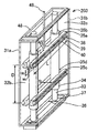
- the box-type filter element 3 includes a pair of planar filter media 31a and 31b arranged opposite to each other, and three blocking plates 32 (an upper end plate 32a and a front side plate 32b substantially orthogonal thereto).
- the rear plate 32c) forms a substantially rectangular parallelepiped box having an opening on the lower side, and two sets of the fixed pipe 33 and the movable pipe 34 arranged in parallel inside the box are orthogonal to these.
- the backwashing mechanism is composed of two pairs of backwashing heads 35a and 35b;
- the flat filter medium 31 may be any layer as long as it is stacked in a plurality of layers and the innermost layer has the finest mesh.
- a plurality of laminated metal meshes are sintered to improve shape retention and are formed into a flat shape. And those that are sintered, those that consist of flat notch wires, and those that consist of wedge wires.
- the innermost layer mesh size may be 10 to 200 ⁇ m, and the outer layer mesh size may be appropriately selected from 200 to 5000 ⁇ m.
- the reinforcing mesh and the protective mesh other than the innermost layer are related to the strength of the box-type filter element 31, and the number of layers, the size of the mesh, and the wire diameter are selected so that the required strength can be obtained.
- plain weave, twill weave, satin weave, tatami weave, twill tatami weave and the like can be applied as the mesh weave.
- the innermost layer is a metal mesh, and is sintered in a state where a flat punching plate having countless square holes, for example, and a reinforcing member in which a plurality of thin rods are arranged in the vertical and horizontal directions are arranged on the outer side. May be.
- the upper end plate 32a, the front side plate 32b, and the rear side plate 32c have a box-shaped structure together with the pair of planar filter media 31a and 31b, and the planar filter media 31a, 31b is held. Of these, the upper end plate 32 a fixes and holds the upper end portion of the fixed tube 33.
- a frame-like end member 36 is provided around the opening so that it can be fitted into the through hole 10 of the partition wall 2.
- a lower end portion of the fixed tube 33 is supported by a support member 37 installed in the opening of the end member 36.
- the fixed tube 33 is provided so as to be parallel to the surface of the planar filter medium 31, the upper end is fixed to the upper end plate 32 a, the lower end is supported by the support member 37, and the lower end Is connected to the backwash fluid discharge pipe 4.
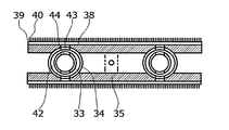
- the movable tube 34 is fitted to the outside of the fixed tube 33 so as to be movable in the axial direction, and a backwash head 35 is attached to the outer peripheral side thereof.
- the structure in which the fixed tube 33 and the movable tube 34 are combined is such that the inner peripheral surface of the movable tube 34 is fitted to the outer peripheral surface of the fixed tube 33 at both ends in the axial direction.
- sticker 41 is provided in this part.
- the movable tube 34 is guided by the fixed tube 33 at the fitting portions at both ends, and can move in the axial direction.
- a cylindrical gap 42 is formed between the inner peripheral surface of the movable tube 34 and the outer peripheral surface of the fixed tube 33.
- a movable tube through hole 43 that penetrates from the gap 42 to the outer peripheral surface side of the movable tube 34 and communicates the gap 42 and the backwash head 35, and the fixed tube 33 from the gap 42.
- a fixed tube through hole 44 penetrating to the inner side of the tube.
- the gap 42 has an axial length that can maintain communication between the movable tube through hole 43 and the fixed tube through hole 44 even when the movable tube 34 moves within a predetermined range. It can be secured.
- the upper end side of the fixed pipe is closed so that the stock solution does not flow in, but the lower end side is opened so that it can be connected to the backwash fluid discharge pipe 4 described later.
- two sets of the fixed tube 33 and the movable tube 34 are arranged in parallel, and the backwash head 35 is attached so that the longitudinal direction is orthogonal to the axial direction.
- This also suppresses rolling (rotational error around the moving axis) when the backwash head 35 is moved, and the contact pressure or gap between the backwash head 35 and the flat filter medium 31 is appropriately set in the entire longitudinal direction of the backwash head 35. And uniform backwashing is possible.
- only one set of the fixed tube 33 and the movable tube 34 is provided at the center in the longitudinal direction of the backwash head 35, and the rolling of the backwash head 35 is restricted by contact with the flat filter medium 31.
- rolling of the backwash head 35 may be regulated by using a set of a fixed tube 33 and a movable tube 34 and other known guide mechanisms in combination.
- the two sets of the fixed tube 33 and the movable tube 34 are both used as the discharge passage for the backwash fluid, thereby performing backwashing with a uniform and sufficient flow rate.
- discharge of the backwash fluid from all the backwash heads 35 is performed in one of the two sets of the fixed tube 33 and the movable tube 34, and the other set of the fixed tube 33 and the movable tube 34 is You may use as a guide which only guides the backwash head 35, without using it as a discharge passage of backwash fluid.
- the lower end of the fixed pipe 33 may be closed without being connected to the backwash fluid discharge pipe 4.
- the backwash fluid discharge pipe 4 only needs to be connected to one fixed pipe 33, so that the structure of the apparatus is simplified and the workability during maintenance is further improved.
- the backwashing head 35 is arranged with an inflow port 38 in contact with the inside of the box-shaped filter element 3 of the flat filter medium 31, and the fluid in the filtrate chamber 9 flows through the flat filter medium 31 to the flow.
- the flat filter medium 31 is backwashed by flowing from the inlet 38.
- two pairs of backwash heads 35a, 35b and 35c, 35d are arranged on the flat surface.
- the filter media 31a and 31b are attached to the movable tube 34 so as to be in contact with the inside of the box-shaped filter element 3 and are arranged back to back, and have a cross-beam shape as a whole.
- the pair of flat filter media 31a and 31b can be backwashed simultaneously, and the two pairs of upper and lower backwash heads 35a, 35b and 35c, 35d are arranged with an interval D in the axial direction of the movable tube 34. Therefore, the two axial locations of each planar filter medium 31 can be backwashed simultaneously, and the entire axial direction of the planar filter media 31 can be backwashed with a small movable range.
- the “inlet 38” is a recess formed in the backwash head surface around the communication hole from the backwash head 35 to the movable tube 34, and the backwash head surface during backwashing. And a portion of the filter medium that forms a lower pressure space than the filtrate chamber 9. The same applies to the “inlet 138” of the second embodiment to be described later.
- the inlet 38 of the backwash head 35 has an elongated shape, and is arranged so that the longitudinal direction is perpendicular to the axis of the fixed tube 33, and the dimension L in the longitudinal direction is the planar shape.
- the size of the filter medium 31 can be backwashed simultaneously in the entire direction perpendicular to the axis of the fixed tube 33. Accordingly, the entire surface of the planar filter medium 31 can be backwashed by moving only in the axial direction between the fixed tube 33 and the movable tube 34.
- the width w1 of the backwashing head 35 is small, filtration can be continued even during backwashing at a portion of the filter surface where the backwashing head 35 is not in contact, and high use efficiency of the filtration device can be secured. ing. Further, there is a space s1 between each pair of backwashing heads 35 arranged back to back so that the stock solution can pass therethrough.
- the width w2 is 3 mm or more, and the length L is 20 mm or more.
- the width w2 is preferably 4 mm or more, more preferably 6 mm or more, and the length L is preferably 50 mm or more, more preferably 60 mm or more.
- the flow path diameter of the backwash fluid discharge path after the inlet 38 is 4 mm or more, more preferably 6 mm or more.
- removal brushes 40 are disposed on the bank-shaped portions 39 provided on both sides in the width direction of the inlet 38 of the backwash head 35, and the flat filter medium 31 is moved by the movement of the backwash head 35. It is configured to scrape the trapped material. Thereby, the backwashing effect can be enhanced.
- the material of the bristles of the removal brush 40 is, for example, natural or synthetic fiber, or a metal wire such as steel, copper, or brass, and is selected according to the purpose of use of the filtration device and the fluid to be passed.
- a scraper made of metal, resin or rubber formed in a blade shape or a spatula shape is provided on the bank 39 and is slidably contacted with the surface of the flat filter medium 31. You may make it remove a thing.
- the backwashing head is in contact with the surface” or “the inlet is in contact with the surface” means that of the bank-like portion 39, the removal brush 40 or the scraper that is closest to the planar filter medium 31. It means contacting the surface of the flat filter medium 31.
- a connecting member 45 that connects these two backwashing heads 35a and 35b is installed at the center of the upper pair of backwashing heads 35a and 35b, and a through-hole 47 in which a drive rod 46 is drilled in the upper separator 32a from the connecting member 45. It protrudes from the upper surface of the box-shaped filter element 31.
- a seal (not shown) is provided between the through hole 47 and the drive rod 46 so that fluid does not leak.
- a casing lid 1b is placed above the box-shaped filter element 3 (3a, 3b) so as to cover the casing main body 1a.
- the casing lid 1b is also provided with a through hole (not shown) through which the drive rod 46 (see FIG. 2) extends upward.
- a seal (not shown) is also provided between the through hole and the drive rod 46.
- an air cylinder is attached as a drive source 5 in the vertical direction via an adapter 11, and is detachably connected to the drive rod 46.
- any known drive source such as a hydraulic cylinder, an electric motor and a feed screw mechanism driven by the hydraulic cylinder can be used instead of the air cylinder.
- a backwash fluid discharge pipe 4 is connected to the discharge side of the fixed pipe 33 of the box-type filter element 3 (3a, 3b).
- the backwashing fluid discharge pipe 4 discharges the backwashing fluid and the removed trapped substance to the outside of the casing 1 when the box-type filter element 3 is backwashed, and is a straight line extending in the radial direction of the casing 1.
- a branch pipe 4b which branches from the pipe 4a and extends upward and is connected to a fixed pipe of each box-type filter element 3.
- a discharge port 4 c at the tip of the straight pipe 4 a protrudes outside the casing 1.
- each box-type filter element 3 (3a, 3b) is fitted into the through hole 10 of the partition wall 2, the fixed pipe 33 is fitted to the branch pipe 4b of the backwash fluid discharge pipe 4, It is designed to be hermetically connected by a seal. Accordingly, the box-type filter element 3 can be easily attached and detached, and high maintainability is ensured.
- An open / close valve (not shown) is connected to the discharge side of the discharge port 4 c of the backwash fluid discharge pipe 4.
- This on-off valve opens and closes the backwashing fluid discharge system including the backwashing head 35, the backwashing fluid discharge passage and the backwashing fluid discharge pipe 4, and is opened during backwashing of the filtration device. Sometimes it is blocked.
- Discharge side of the opening and closing valve, low pressure side of the pressure of the fluid outlet 7, for example, is opened to the atmospheric pressure P 0.
- the operation of the first embodiment of the filtration device configured as described above will be described with reference to FIG. 1 (during filtration) and FIGS. 5 and 6 (during backwashing).
- the backwash head 35 is stopped while being in contact with a predetermined portion of the flat filter medium 31.
- the on-off valve of the backwash fluid discharge system is closed, and backwashing by the backwash head 35 is not performed.
- the fluid to be filtered flows from the fluid inlet 6 into the stock solution chamber 8 of the housing 1 as indicated by an arrow A.
- the pressure of the fluid (primary pressure P 1 ) is pressurized by a pump (such as a centrifugal pump) and is higher than the pressure of the filtrate chamber 9 (secondary pressure P 2 ).
- the filter element 3a, 3b is filtered by passing through the portion of the flat filter medium 31 where the backwash head 35 is not in contact with the filter element 3a, 3b and flowing out into the filtrate chamber 9 outside. At this time, foreign matters such as plankton and algae are captured on the inner side surface of the box-shaped filter element 3 of the planar filter medium 31.
- the fluid filtered through the planar filter media 31a and 31b flows out from the fluid outlet 7 as indicated by an arrow B.
- the opening / closing valve of the cleaning fluid discharge system is opened, and the inside of the cleaning fluid discharge system is communicated with a low pressure side such as the atmospheric pressure P 0, and the pressure is reduced.
- a low pressure side such as the atmospheric pressure P 0, and the pressure is reduced.
- the flow of fluid into the backwash head 35 is started, and the backwash head 35 is reciprocated in the vertical direction by the air cylinder (5).
- the fluid passes through the planar filter medium 31 from the inside of the box-shaped filter element 3 as in the filtration. It flows out into the filtrate chamber 9 on the outside, and filtration is continued.
- the backwash head 35 is reciprocated in the vertical direction by the air cylinder (5), thereby backwashing the entire surface of each planar filter medium 31.
- the removal brush 40 is disposed on the bank 39 around the inlet 38 of the backwashing head 35, the trapped matter of the planar filter medium 31 is scraped by the movement of the backwashing head 35. Be dropped.
- part of the fluid also flows into the inflow port 38 of the backwash head 35 through the gap between the bristles of the removal brush 40 also from the inside of the box-shaped filter element 3, so that the trapped object is scraped off.
- the holes of the mesh for allowing the fluid to pass through are parallel to the axis of the fixed tube. It is configured to be a hole.
- a flat filter medium 31 having a general square mesh hole is used for filtration, depending on the use conditions, particles of the same size as the mesh hole may get stuck, causing clogging without being removed. There is. In addition, fibrous foreign matters may be entangled with the lattice of the net and cannot be easily removed.
- the mesh holes are elongated, particles having a size substantially the same as the width of the elongated holes may be trapped, but there is a low possibility that a plurality of small particles will be trapped. In addition, the trapped particles are easily removed because they are restricted only from the width direction of the long holes. Since the fibrous foreign matter is also difficult to be wound in the longitudinal direction of the long hole, it is difficult to get entangled.
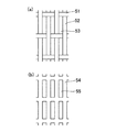
- FIG. 7A and 7B show structural examples of the innermost layer of the planar filter medium 31 having such long hole openings.
- the long holes 53 are realized by making the interval in the axial direction of the fixed pipes of the wire meshes 51 and 52 longer than the interval in the orthogonal direction.
- the innermost layer of the planar filter medium 31 is a punching metal 54, and a long hole 55 parallel to the axis of the fixed tube is formed.
- any structure other than these can be used for the structure of the innermost layer that realizes the long holes.
- the dimensional ratio of the long hole in the long axis direction / short axis direction is preferably 2 or more, and more preferably 3 or more.
- a coarser mesh for reinforcement may be laminated on the outer side of the innermost layer having these configurations as described above.
- the axial pitch pa of the fixed pipe of the innermost mesh for passing the fluid through is the orthogonal pitch pt. Has been bigger.
- FIG. 8A shows an innermost layer of a flat filter medium 31 made of a plain woven mesh.
- the mesh extends in the circumferential direction of the planar filter medium 31 and is parallel to the plurality of vertical lines 56 (lateral direction in the figure) arranged at intervals with a large pitch pa in the axial direction and the axis of the fixed tube.
- a plurality of horizontal lines 57 and 58 (longitudinal direction in the figure) which extend in the direction and are closely arranged with a small pitch pt in the orthogonal direction are formed by tatami weaving.
- the adjacent horizontal lines 57 and 58 are woven so as to wrap around from the different sides of each vertical line 56, so that a gap 59 is formed between the horizontal lines 57 and 58 and the vertical line 56. (Refer to FIG. 8 (b)), and the fluid is filtered by passing therethrough.
- the groove portion 60 is formed between every other horizontal line 57, 57 or 58, 58, foreign matters such as particles and fibers may be caught in the groove portion 60.
- the direction of the horizontal lines 57 and 58 is parallel to the axis of the fixed tube (the axis of the planar filter medium 31), so the direction of the groove 60 is also the axial direction of the planar filter medium 31.
- the removal brush 40 provided on the backwash head 35 easily removes foreign matters such as particles and fibers caught in the groove 60 by moving in the axial direction.
- the structure of the innermost layer in which the axial pitch pa of the fixed pipe of the mesh of the planar filter medium 31 is larger than the orthogonal pitch pt may be any structure other than the above.
- the same effect can be obtained even when a twill woven mesh is used.
- the use of the planar filter medium 31 shown in FIGS. 7 and 8 was captured by the planar filter medium 31 by the removal brush 40 provided in the backwash head 35. Since the foreign matter is easily removed, the effect of backwashing is further enhanced.
- the present invention is not limited to those shown in FIGS. A washing effect can be obtained.
- the filtration device of the present embodiment uses a cylindrical filter element having only one surface opened.
- This filter device is obtained by replacing the box-type filter element 3 with a cylindrical filter element in the filter device of the first embodiment shown in FIG. 1, and the shape of the filter element and the through-hole 10 of the partition wall 2 to which the filter element is attached. Since the filter device is the same as the filter device of the first embodiment except for, the description of the entire filter device is omitted, and only the cylindrical filter element is described.
- FIG. 9 is a schematic perspective view showing the cylindrical filter element 103 of the present embodiment.
- This cylindrical filter element 103 has a cylindrical filter medium 131, and allows the target fluid to pass from the inside to the outside to capture and filter solids and gel-like dust contained in the fluid.
- the cylindrical filter medium 131 is backwashed by a backwashing mechanism (133, 134, 135a, 135b) provided inside.
- the cylindrical filter element 103 and the cylindrical filter medium 131 are formed in a cylindrical shape.
- the cylindrical filter element 103 vertically with its opening end facing downward, heavy captured objects such as pebbles that are difficult to remove by the backwashing mechanism among the captured objects can easily fall to the bottom of the housing 1. Therefore, the failure of the backwash mechanism can be reduced.
- One or a plurality of the cylindrical filter elements 103 are arranged in the housing 1.
- the cylindrical filter element 103 includes a cylindrical filter medium 131 that forms a cylindrical surface of the cylindrical filter element 103 and that is open on both upper and lower sides, and a blocking plate 132 that closes the upper surface thereof. And a lower opening is formed in the cylindrical body, and one set of a fixed tube 133 and a movable tube 134 disposed in the axial direction is disposed inside the cylindrical body, and an axial direction is formed around the movable tube 134. It has a backwashing mechanism composed of two annular backwashing heads 135a and 135b attached with an interval.
- the cylindrical filter medium 131 may be formed by stacking a plurality of layers and forming the innermost layer with the finest mesh, but formed into a cylindrical shape instead of a flat shape. There must be.
- the closing plate 132 has a disk shape, closes the upper surface of the tubular filter medium 131, and fixes and holds the upper end of the fixed tube 133.
- the lower end part of the said cylindrical filter medium 131 is opening, the cyclic
- the lower end portion of the fixed tube 133 is supported by a support member 137 installed in the opening of the end member 136.
- the fixed pipe 133 and the movable pipe 134 fitted to the outside of the fixed pipe 133 movably guide the backwash head 135 and form a backwash fluid discharge passage.
- the fixed tube 133 is provided on the central axis of the cylindrical filter medium 131, the upper end is fixed to the blocking plate 132, the lower end is supported by the support member 137, and the lower end is The backwash fluid discharge pipe 4 is connected.
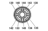
- the movable tube 134 is fitted to the outside of the fixed tube 133 so as to be movable in the axial direction, and each backwash head 135 is attached to the outer peripheral side of the movable tube 134 via four water pipes 149. Yes.
- the contact pressure or gap between the backwash head 135 and the planar filter medium 31 is determined by the distance between the cylindrical filter medium 131 and the fixed tube 133 fixed to the cylindrical filter element 103. Assembling adjustment is unnecessary or easy.
- the structure in which the fixed tube 33 and the movable tube 34 are combined is shown in a schematic cross-sectional view 10 and a cross-sectional view taken along the line EE of FIG.
- This structure movably guides the backwash head 135 and forms a backwash fluid discharge passage, and is basically the same as the structure shown in FIG. 3 of the first embodiment. Is omitted.
- the moving pipe 134 and the backwash head 135 are connected via a water pipe 149, and the inlet 138 of the backwash head 135 and the inside of the moving pipe 134 are communicated via the water pipe 149.
- the backwash water flowing into the backwash head 135 is different from the apparatus of the first embodiment in that it flows through the water pipe 149 and flows into the movable pipe 134.
- the lower end side of the fixed pipe 133 is opened and can be connected to the backwash fluid discharge pipe 4.
- the backwash head 135 has an inlet 138 in contact with the inside of the cylindrical filter medium 131, and allows the fluid in the filtrate chamber 9 to flow from the inlet 138 through the cylindrical filter medium 131.
- the cylindrical filter medium 131 is backwashed.
- the upper and lower backwash heads 135a and 135b are respectively connected to the movable pipe 134 via four water pipes 149. It is attached. Since the upper and lower backwash heads 35a and 35b are arranged with a gap D in the axial direction of the movable tube 34, two axial locations of the cylindrical filter medium 131 can be backwashed simultaneously, and the movable range is small. Thus, the entire axial direction of the tubular filter medium 131 can be backwashed.
- Each backwash head 135 has an annular shape, and has a groove-shaped inlet 138 that is continuous in the circumferential direction on the outer peripheral portion, and has a size that allows the entire circumference to be backwashed simultaneously. Accordingly, the entire surface of the cylindrical filter medium 131 can be backwashed by moving only in the axial direction between the fixed tube 133 and the movable tube 134.
- the width w3 of the backwash head 135 is small, filtration can be continued even during backwashing at a portion of the filter surface where the backwash head 135 is not in contact with the backwash head 135, so that high utilization efficiency of the filtration device can be secured.
- removal brushes 140 are disposed on the bank-shaped portions 139 provided on both sides in the width direction of the inlet 138 of the backwash head 135, as in the first embodiment.
- the trapped material of the planar filter medium 31 is scraped off by the movement of. Thereby, the backwashing effect can be enhanced.
- a drive rod 146 protrudes from the upper surface of the cylindrical filter element 103 from the upper surface of the upper backwash head 135a through the through hole 147 formed in the closing plate 132.
- a seal (not shown) is provided between the through hole 147 and the drive rod 146 so that fluid does not leak.
- FIG. 12 is a schematic cross-sectional view showing a state during filtration of the third embodiment of the filtration device according to the present invention.
- the filtration device of the present embodiment uses a box-type filter element having two open upper and lower opposing surfaces, and these two openings communicate with stock solution chambers provided at the upper and lower portions in the casing, respectively. It is a form.
- This configuration has the following advantages (1) and (2). (1) Since the stock solution is also supplied from the stock solution chamber provided in the upper portion of the casing through the upper opening, the filtration speed is unlikely to decrease. (2)
- the backwashing mechanism, excluding the fixed tube, can be pulled out from the opening on the upper surface during maintenance, and the inner surface of the box-shaped filter element can be removed from the opening using a jet shower, etc. Can be washed.
- the filtration device of the third embodiment shown in FIG. 12 is different from the device of the first embodiment shown in FIG. 1 in that a box-type filter element 203 having two open upper and lower surfaces is used and the casing 1
- a second partition wall 12 is provided in parallel to the partition wall 2 on the upper end side of the box-type filter element 203 inside, and the upper end portion of the box-type filter element 203 is fitted and held in the through-hole 13. 12, a second stock solution chamber 8 b isolated from the filtrate chamber 9 is formed.
- the second undiluted solution chamber 8b communicates with the partition wall through the box-type filter element 3 and the lower undiluted solution chamber 8 (referred to as the second undiluted solution chamber 8a in this embodiment).
- FIG. 13 is a schematic perspective view showing a box-type filter element 203 of the filtration device of FIG.
- This box-shaped filter element 203 has a box-shaped shape in which two upper and lower opposing surfaces are open. Compared with the box-shaped filter element 3 in FIG. 2, the upper surface is closed instead of the upper end plate 32a. The difference is that a frame-shaped upper end member 48 having the above is provided. As a result, the upper end portion of the fixed tube 33 is a free end that is not fixed, and the lower end portion is fixed only by the bridging member 37.
- the opening on the upper surface is large enough to allow the moving tube 34, the backwashing head 35, and the drive rod 46 to pass through, so that the moving tube integrated with the backwashing head 35 and the drive rod 46 passes through this opening.
- 34 can be pulled out from the fixed tube 33 or inserted into the fixed tube 33.
- the configuration of the filtration device and the box-type filter element 203 of the present embodiment is the same as that of the first embodiment. Therefore, the components common to the first embodiment shown in FIGS. The same reference numerals are given and description thereof is omitted.
- the operation of the filtration device of the third embodiment configured as described above is basically the same as the operation of the filtration device of the first embodiment, but the second device passes through the opening on the upper surface. Since the stock solution is also supplied from the stock solution chamber 8b, the filtration speed is unlikely to decrease. That is, as described in the description of the first embodiment, there is a space s1 between each pair of backwash heads 35 arranged back to back of the box-shaped filter element 203 so that the stock solution can pass therethrough. However, depending on the use conditions, the space s1 of one box-type filter element 203 may be clogged with foreign substances in the stock solution, and the stock solution from the first stock solution chamber 8a may not flow easily. Even in that case, since the stock solution supplied to the second stock solution chamber through the other box-type filter element 203 is supplied to the one box-type filter element 203 from the opened upper surface, the filtration speed is maintained. it can.
- the moving tube 34, the backwash head 35, and the drive rod 46 are integrally formed in a box shape without removing the second partition wall 12 or the box-shaped filter element 203.
- the filter element 3 can be pulled out or inserted.
- the extracted moving tube 34, backwash head 35, drive rod 46, and the remaining box-shaped filter element 203 can be cleaned with a jet shower or the like.
- the maintenance becomes easier than in the case of the first embodiment.
- the box-shaped filter element 203 can be removed from the partition wall 2 in the same manner as in the first embodiment, and disassembly and cleaning can be performed. is there.
- the filtration device of the present embodiment uses a cylindrical filter element in which two upper and lower opposing surfaces are open.
- This filter device is the same as the filter device of the third embodiment shown in FIG. 12, except that the box-type filter element 203 is replaced with a cylindrical filter element, and the filter element and the through-hole 10 of the partition wall 2 to which the filter element is attached. Since it is the same as the filtration device of the third embodiment except for the shape, description of the entire filtration device is omitted, and only the filter element is described.
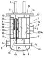
- FIG. 14 is a schematic perspective view showing a cylindrical filter element 303 of the filtration device of the present embodiment.
- the cylindrical filter element 303 has a cylindrical shape in which two upper and lower opposing surfaces are open.
- the cylindrical filter element 303 is formed in a cylindrical shape.
- an annular upper end member 148 having an opening is provided instead of closing the upper surface with a closing plate 132.
- the upper end portion of the fixed tube 133 is a free end that is not fixed, and the lower end portion is fixed only by the bridging member 137.
- the opening on the upper surface is large enough to allow the movable tube 134, the backwash head 135, and the drive rod 146 to pass through, the movable tube integrated with the backwash head 135 and the drive rod 146 passes through this opening. 134 can be extracted from the fixed tube 133 or inserted into the fixed tube 33.
- the configuration of the cylindrical filter element 303 of this embodiment is the same as that of the cylindrical filter element 103 of the second embodiment, and therefore, in FIG. 14, the configuration is the same as that of the second embodiment shown in FIG.
- the same reference numerals are given to the constituent elements, and the description thereof is omitted.
- the operation of the filtration device of the fourth embodiment configured as described above is basically the same as the operation of the filtration device of the third embodiment using the box-type filter element 203 having two open surfaces. is there. Similar to the third embodiment, even when the space s2 of one cylindrical filter element 303 is clogged with foreign substances in the stock solution and the stock solution from the first stock solution chamber 8a becomes difficult to flow, other tubular filter elements Since the stock solution supplied to the second stock solution chamber through 303 is supplied to the one cylindrical filter element 303 from the opened upper surface, the filtration rate can be maintained.
- the movable tube 134, the backwash head 135, and the drive rod 146 are integrally formed without removing the second partition wall 12 or the tubular filter element 303.
- the filter element 303 can be pulled out or inserted.
- the extracted moving tube 134, backwash head 135, drive rod 146, and the remaining cylindrical filter element 303 can be cleaned with a jet shower or the like.
- the filtering device having the plurality of filter elements 3, 103, 203, and 303 is shown.
- the number of filter elements may be one.
- the cylindrical filter elements 103 and 303 are shown as cylindrical filter elements having a cylindrical filter medium.
- the present invention is not limited to the cylindrical type.
- a cylindrical filter element having a cylindrical filter medium having a polygonal cross section may be used. Even in this case, the stock solution flowing in from the open surface is filtered from the inside to the outside, and the filter can be backwashed by arranging a backwash mechanism comprising a fixed tube, a movable tube and a backwash head inside. it can.
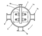
- FIG. 11 is a schematic cross-sectional view showing a modification of the filtration device of the present invention.
- the casing of this filtration device further includes a second fluid outlet that communicates with the stock solution chamber and discharges the fluid before filtration.
- FIG. 11 other than the casing of the filtration device shown in FIG. 11 is the same as the filtration device of the first embodiment shown in FIG.
- portions other than the casing of the filtration device of the present modification are not limited to this, and may be the same as the filtration devices of the second to fourth embodiments shown in FIG.
- FIG. 11 is different from the filtration device of FIG. 1 only in that a second fluid outlet 7b is provided so as to communicate with the stock solution chamber 8 of the casing body 1a.
- the configuration of the box-type filter element 3 is also the same as that of the first embodiment.
- FIG. 11 also shows valves 14, 15, 16 provided at the fluid inlet 6, the fluid outlet 7 communicating with the filtrate chamber (also referred to as the first fluid outlet 7a in the present embodiment), and the second fluid outlet 7b, respectively. Show.
- the second fluid outlet 7 b is disposed in the same direction as the first fluid outlet 7 a for convenience of the pipe 18 to be connected, and as a result, is provided so as to face the fluid inlet 6. Yes.
- the direction of the straight portion 4a of the backwash fluid discharge pipe 4 is set to be orthogonal to the direction connecting the fluid inlet 6 and the second fluid outlet 7b so as not to interfere with them.
- the configuration is not limited to this, and the first fluid outlet 7a and the second fluid outlet 7b may be provided in a direction orthogonal to the fluid inlet 6 as long as they do not interfere with the backwash fluid discharge pipe 4 or the like.
- FIG. 12 shows a cross section along line XX of the filtration device of FIG. 11 by a solid line (the valve is not shown).
- the positions of the first and second fluid outlets 7a and 7b may be provided at a position orthogonal to the fluid inlet 6 as indicated by a two-dot chain line, and this position depends on the convenience of the piping connected to the filtration device. Can be selected.
- the second fluid outlet 7b can be closed with a lid or the like and used as a work hole during maintenance.
- the operation of the filtration device of the present embodiment configured as described above is basically the first embodiment shown in FIG. 1 except that the filtration of the stock solution and the passage of the stock solution can be switched inside the filtration device.
- the operation of the filtration device is the same.
- valve 16 provided at the fluid inlet 6 and the valve 15 provided at the first fluid outlet 7a are opened, and the valve 16 provided at the second fluid outlet 7b is closed, so that the fluid flows upstream.
- valve 16 provided at the fluid inlet 6 and the valve 16 provided at the second fluid outlet 7b are opened and the valve 15 provided at the first fluid outlet 7a is closed, so that the fluid is
- the upstream pipe 17 flows into the downstream pipe 19 through the stock solution chamber 8 without being filtered, and joins the downstream pipe 18.
- backwashing using the backwashing head etc. of this filtration apparatus is possible at the time of filtration and at the time of passage.
- the present filtration device becomes a part of the main pipe, and it is not necessary to provide a bypass pipe having a valve between the fluid inlet 6 and the first fluid outlet 7a. Miniaturization can be achieved.
Landscapes
- Chemical & Material Sciences (AREA)
- Chemical Kinetics & Catalysis (AREA)
- Filtration Of Liquid (AREA)
- Filtering Materials (AREA)
Priority Applications (4)
| Application Number | Priority Date | Filing Date | Title |
|---|---|---|---|
| US15/028,406 US10046253B2 (en) | 2014-10-03 | 2015-03-25 | Filtration device |
| KR1020167006186A KR102388304B1 (ko) | 2014-10-03 | 2015-03-25 | 여과 장치 |
| DE112015004545.7T DE112015004545T5 (de) | 2014-10-03 | 2015-03-25 | Filtrationsvorrichtung |
| CN201580001830.9A CN105682766B (zh) | 2014-10-03 | 2015-03-25 | 过滤装置 |
Applications Claiming Priority (2)
| Application Number | Priority Date | Filing Date | Title |
|---|---|---|---|
| JP2014-204991 | 2014-10-03 | ||
| JP2014204991A JP6373711B2 (ja) | 2014-10-03 | 2014-10-03 | 濾過装置 |
Publications (1)
| Publication Number | Publication Date |
|---|---|
| WO2016051824A1 true WO2016051824A1 (ja) | 2016-04-07 |
Family
ID=55629884
Family Applications (1)
| Application Number | Title | Priority Date | Filing Date |
|---|---|---|---|
| PCT/JP2015/059172 Ceased WO2016051824A1 (ja) | 2014-10-03 | 2015-03-25 | 濾過装置 |
Country Status (6)
| Country | Link |
|---|---|
| US (1) | US10046253B2 (https=) |
| JP (1) | JP6373711B2 (https=) |
| KR (1) | KR102388304B1 (https=) |
| CN (1) | CN105682766B (https=) |
| DE (1) | DE112015004545T5 (https=) |
| WO (1) | WO2016051824A1 (https=) |
Cited By (5)
| Publication number | Priority date | Publication date | Assignee | Title |
|---|---|---|---|---|
| CN108434840A (zh) * | 2018-05-09 | 2018-08-24 | 南施西 | 滤网防堵结构的污水处理装置 |
| CN108905328A (zh) * | 2018-07-01 | 2018-11-30 | 南施西 | 具有清理结构的污水处理管道过滤装置 |
| CN111035978A (zh) * | 2019-12-26 | 2020-04-21 | 中国能源建设集团华东电力试验研究院有限公司 | 一种凝汽器循环水管二次滤网控制装置及其操作方法 |
| CN112933721A (zh) * | 2021-02-06 | 2021-06-11 | 云南师范大学 | 一种乳制品加工用杂质过滤装置 |
| CN114307363A (zh) * | 2021-12-31 | 2022-04-12 | 中国农业大学 | 一种自动反冲洗离心-砂石一体式过滤器 |
Families Citing this family (12)
| Publication number | Priority date | Publication date | Assignee | Title |
|---|---|---|---|---|
| JP6343231B2 (ja) * | 2014-12-02 | 2018-06-13 | 富士フィルター工業株式会社 | 濾過装置 |
| GB2557987A (en) * | 2016-12-21 | 2018-07-04 | Eaton Tech Ip Gmbh & Co Kg | Filter |
| WO2018235084A1 (en) * | 2017-06-23 | 2018-12-27 | Inova Water Systems Y.G Ltd | Self-cleaning filter apparatus |
| IL258698A (en) * | 2018-04-15 | 2018-05-31 | Amiad Water Systems Ltd | A control mechanism for self-cleaning filter systems |
| US12403494B2 (en) | 2020-08-26 | 2025-09-02 | Deere & Company | Work vehicle sprayer system and method with nozzle monitoring |
| US12330179B2 (en) | 2020-08-26 | 2025-06-17 | Deere &Company | Work vehicle sprayer system and method with pinching nozzle apparatus |
| US12083543B2 (en) | 2020-08-26 | 2024-09-10 | Deere & Company | Work vehicle sprayer system and method with switching nozzle apparatus |
| US11896989B2 (en) * | 2020-08-26 | 2024-02-13 | Deere & Company | Work vehicle sprayer system and method with self-cleaning filter apparatus |
| CN112191007A (zh) * | 2020-09-28 | 2021-01-08 | 宁夏水投科技股份有限公司 | 自动化水处理反冲洗装置 |
| CN112587974A (zh) * | 2020-11-04 | 2021-04-02 | 洛阳功航机械科技有限公司 | 一种催化油浆在线过滤装置 |
| CN114653708B (zh) * | 2022-03-09 | 2023-07-25 | 云南曲靖钢铁集团凤凰钢铁有限公司 | 一种无缝钢管圆管高纯度管坯冶炼系统 |
| CN116531947B (zh) * | 2023-05-26 | 2025-09-23 | 江苏南大生态环境建设有限公司 | 一种工业废水回用处理装置 |
Citations (9)
| Publication number | Priority date | Publication date | Assignee | Title |
|---|---|---|---|---|
| US2858894A (en) * | 1954-06-14 | 1958-11-04 | Swan M Akeyson | Screen pipe |
| JPS443739Y1 (https=) * | 1965-05-29 | 1969-02-12 | ||
| JPS512384Y2 (https=) * | 1971-04-06 | 1976-01-23 | ||
| JPS6024314U (ja) * | 1983-07-25 | 1985-02-19 | ダイハツデイ−ゼル株式会社 | 自動逆洗式濾過器 |
| JPH0268380A (ja) * | 1988-09-02 | 1990-03-07 | Aikawa Tekko Kk | 製紙用スクリーン |
| JPH10118430A (ja) * | 1996-10-16 | 1998-05-12 | N B C Kogyo Kk | ポリアセタール繊維製メッシュ織物及びそれを用いたフィルター部材 |
| WO2011108541A1 (ja) * | 2010-03-02 | 2011-09-09 | Jfeエンジニアリング株式会社 | 濾過装置及びバラスト水処理装置 |
| JP2014094346A (ja) * | 2012-11-09 | 2014-05-22 | Fuji Filter Kogyo Kk | 濾過装置 |
| JP2015080754A (ja) * | 2013-10-22 | 2015-04-27 | Jfeエンジニアリング株式会社 | 濾過装置及びバラスト水処理装置 |
Family Cites Families (5)
| Publication number | Priority date | Publication date | Assignee | Title |
|---|---|---|---|---|
| JPS5222389Y2 (https=) | 1974-06-19 | 1977-05-23 | ||
| KR101012752B1 (ko) * | 2010-06-11 | 2011-02-08 | 주식회사 파나시아 | 밸러스트수 처리용 여과장치 |
| DE112013000673B4 (de) | 2012-01-24 | 2022-12-08 | Fuji Filter Manufacturing Co., Ltd. | Filtervorrichtung |
| JP6060610B2 (ja) * | 2012-10-15 | 2017-01-18 | 信越化学工業株式会社 | 屋外タンクの防水施工方法 |
| KR101741153B1 (ko) * | 2013-02-25 | 2017-06-15 | 주식회사 파나시아 | 컴팩트하고 운용성을 높이는 멀티케이지 타입 밸러스트수 여과장치 |
-
2014
- 2014-10-03 JP JP2014204991A patent/JP6373711B2/ja active Active
-
2015
- 2015-03-25 CN CN201580001830.9A patent/CN105682766B/zh active Active
- 2015-03-25 US US15/028,406 patent/US10046253B2/en active Active
- 2015-03-25 DE DE112015004545.7T patent/DE112015004545T5/de not_active Withdrawn
- 2015-03-25 KR KR1020167006186A patent/KR102388304B1/ko active Active
- 2015-03-25 WO PCT/JP2015/059172 patent/WO2016051824A1/ja not_active Ceased
Patent Citations (9)
| Publication number | Priority date | Publication date | Assignee | Title |
|---|---|---|---|---|
| US2858894A (en) * | 1954-06-14 | 1958-11-04 | Swan M Akeyson | Screen pipe |
| JPS443739Y1 (https=) * | 1965-05-29 | 1969-02-12 | ||
| JPS512384Y2 (https=) * | 1971-04-06 | 1976-01-23 | ||
| JPS6024314U (ja) * | 1983-07-25 | 1985-02-19 | ダイハツデイ−ゼル株式会社 | 自動逆洗式濾過器 |
| JPH0268380A (ja) * | 1988-09-02 | 1990-03-07 | Aikawa Tekko Kk | 製紙用スクリーン |
| JPH10118430A (ja) * | 1996-10-16 | 1998-05-12 | N B C Kogyo Kk | ポリアセタール繊維製メッシュ織物及びそれを用いたフィルター部材 |
| WO2011108541A1 (ja) * | 2010-03-02 | 2011-09-09 | Jfeエンジニアリング株式会社 | 濾過装置及びバラスト水処理装置 |
| JP2014094346A (ja) * | 2012-11-09 | 2014-05-22 | Fuji Filter Kogyo Kk | 濾過装置 |
| JP2015080754A (ja) * | 2013-10-22 | 2015-04-27 | Jfeエンジニアリング株式会社 | 濾過装置及びバラスト水処理装置 |
Cited By (6)
| Publication number | Priority date | Publication date | Assignee | Title |
|---|---|---|---|---|
| CN108434840A (zh) * | 2018-05-09 | 2018-08-24 | 南施西 | 滤网防堵结构的污水处理装置 |
| CN108905328A (zh) * | 2018-07-01 | 2018-11-30 | 南施西 | 具有清理结构的污水处理管道过滤装置 |
| CN111035978A (zh) * | 2019-12-26 | 2020-04-21 | 中国能源建设集团华东电力试验研究院有限公司 | 一种凝汽器循环水管二次滤网控制装置及其操作方法 |
| CN111035978B (zh) * | 2019-12-26 | 2023-09-05 | 中国能源建设集团华东电力试验研究院有限公司 | 一种凝汽器循环水管二次滤网控制装置及其操作方法 |
| CN112933721A (zh) * | 2021-02-06 | 2021-06-11 | 云南师范大学 | 一种乳制品加工用杂质过滤装置 |
| CN114307363A (zh) * | 2021-12-31 | 2022-04-12 | 中国农业大学 | 一种自动反冲洗离心-砂石一体式过滤器 |
Also Published As
| Publication number | Publication date |
|---|---|
| US10046253B2 (en) | 2018-08-14 |
| CN105682766A (zh) | 2016-06-15 |
| DE112015004545T5 (de) | 2017-06-14 |
| JP6373711B2 (ja) | 2018-08-15 |
| JP2016073904A (ja) | 2016-05-12 |
| KR102388304B1 (ko) | 2022-04-19 |
| US20160250572A1 (en) | 2016-09-01 |
| CN105682766B (zh) | 2019-05-10 |
| KR20170065461A (ko) | 2017-06-13 |
Similar Documents
| Publication | Publication Date | Title |
|---|---|---|
| JP6373711B2 (ja) | 濾過装置 | |
| JP2016073904A5 (https=) | ||
| JP6343231B2 (ja) | 濾過装置 | |
| CN105531007B (zh) | 过滤装置和滤芯 | |
| KR102156817B1 (ko) | 필터 엘리먼트 및 여과 장치 | |
| JP2016010788A5 (https=) | ||
| US9669335B2 (en) | Filter apparatus | |
| KR102156816B1 (ko) | 여과 장치 | |
| JP6076647B2 (ja) | 濾過装置 | |
| CN101854994A (zh) | 过滤设备 | |
| KR20130016865A (ko) | 역세 가능한 수처리 필터 시스템 및 역세 방법 | |
| JP6608631B2 (ja) | 濾過装置及び濾過装置のフィルター洗浄方法 | |
| JP6718252B2 (ja) | 濾過装置 | |
| JP5203171B2 (ja) | ストレーナ装置 | |
| JP6042700B2 (ja) | 濾過装置 | |
| KR100630372B1 (ko) | 여과장치 | |
| JP6928635B2 (ja) | 濾過装置及び濾過装置のフィルター洗浄方法 | |
| RU2352381C1 (ru) | Фильтр патронный | |
| EP3406325A1 (en) | Filter assembly with filler core |
Legal Events
| Date | Code | Title | Description |
|---|---|---|---|
| ENP | Entry into the national phase |
Ref document number: 20167006186 Country of ref document: KR Kind code of ref document: A |
|
| WWE | Wipo information: entry into national phase |
Ref document number: 15028406 Country of ref document: US |
|
| 121 | Ep: the epo has been informed by wipo that ep was designated in this application |
Ref document number: 15847819 Country of ref document: EP Kind code of ref document: A1 |
|
| WWE | Wipo information: entry into national phase |
Ref document number: 112015004545 Country of ref document: DE |
|
| 122 | Ep: pct application non-entry in european phase |
Ref document number: 15847819 Country of ref document: EP Kind code of ref document: A1 |