WO2016047481A1 - 電動ブレーキシステム - Google Patents
電動ブレーキシステム Download PDFInfo
- Publication number
- WO2016047481A1 WO2016047481A1 PCT/JP2015/075987 JP2015075987W WO2016047481A1 WO 2016047481 A1 WO2016047481 A1 WO 2016047481A1 JP 2015075987 W JP2015075987 W JP 2015075987W WO 2016047481 A1 WO2016047481 A1 WO 2016047481A1
- Authority
- WO
- WIPO (PCT)
- Prior art keywords
- electric brake
- electric
- power supply
- brake
- control amount
- Prior art date
Links
Images


Classifications
-
- B—PERFORMING OPERATIONS; TRANSPORTING
- B60—VEHICLES IN GENERAL
- B60T—VEHICLE BRAKE CONTROL SYSTEMS OR PARTS THEREOF; BRAKE CONTROL SYSTEMS OR PARTS THEREOF, IN GENERAL; ARRANGEMENT OF BRAKING ELEMENTS ON VEHICLES IN GENERAL; PORTABLE DEVICES FOR PREVENTING UNWANTED MOVEMENT OF VEHICLES; VEHICLE MODIFICATIONS TO FACILITATE COOLING OF BRAKES
- B60T8/00—Arrangements for adjusting wheel-braking force to meet varying vehicular or ground-surface conditions, e.g. limiting or varying distribution of braking force
- B60T8/17—Using electrical or electronic regulation means to control braking
-
- B—PERFORMING OPERATIONS; TRANSPORTING
- B60—VEHICLES IN GENERAL
- B60T—VEHICLE BRAKE CONTROL SYSTEMS OR PARTS THEREOF; BRAKE CONTROL SYSTEMS OR PARTS THEREOF, IN GENERAL; ARRANGEMENT OF BRAKING ELEMENTS ON VEHICLES IN GENERAL; PORTABLE DEVICES FOR PREVENTING UNWANTED MOVEMENT OF VEHICLES; VEHICLE MODIFICATIONS TO FACILITATE COOLING OF BRAKES
- B60T13/00—Transmitting braking action from initiating means to ultimate brake actuator with power assistance or drive; Brake systems incorporating such transmitting means, e.g. air-pressure brake systems
- B60T13/74—Transmitting braking action from initiating means to ultimate brake actuator with power assistance or drive; Brake systems incorporating such transmitting means, e.g. air-pressure brake systems with electrical assistance or drive
-
- B—PERFORMING OPERATIONS; TRANSPORTING
- B60—VEHICLES IN GENERAL
- B60T—VEHICLE BRAKE CONTROL SYSTEMS OR PARTS THEREOF; BRAKE CONTROL SYSTEMS OR PARTS THEREOF, IN GENERAL; ARRANGEMENT OF BRAKING ELEMENTS ON VEHICLES IN GENERAL; PORTABLE DEVICES FOR PREVENTING UNWANTED MOVEMENT OF VEHICLES; VEHICLE MODIFICATIONS TO FACILITATE COOLING OF BRAKES
- B60T17/00—Component parts, details, or accessories of power brake systems not covered by groups B60T8/00, B60T13/00 or B60T15/00, or presenting other characteristic features
- B60T17/18—Safety devices; Monitoring
-
- B—PERFORMING OPERATIONS; TRANSPORTING
- B60—VEHICLES IN GENERAL
- B60T—VEHICLE BRAKE CONTROL SYSTEMS OR PARTS THEREOF; BRAKE CONTROL SYSTEMS OR PARTS THEREOF, IN GENERAL; ARRANGEMENT OF BRAKING ELEMENTS ON VEHICLES IN GENERAL; PORTABLE DEVICES FOR PREVENTING UNWANTED MOVEMENT OF VEHICLES; VEHICLE MODIFICATIONS TO FACILITATE COOLING OF BRAKES
- B60T8/00—Arrangements for adjusting wheel-braking force to meet varying vehicular or ground-surface conditions, e.g. limiting or varying distribution of braking force
- B60T8/17—Using electrical or electronic regulation means to control braking
- B60T8/1755—Brake regulation specially adapted to control the stability of the vehicle, e.g. taking into account yaw rate or transverse acceleration in a curve
Definitions
- Patent Document 1 An electric linear actuator using a planetary roller screw mechanism.
- Patent Document 2 A technique for converting the rotational motion of a motor into a linear motion via a linear motion mechanism by depressing a brake pedal and applying a braking force by pressing a brake pad against a brake disc.
- the function of the electric brake device may be deteriorated due to an abnormality in the mechanical parts of the electric actuator or an abnormality in the power supply system. In this case, a desired braking force may not be generated.
- An object of the present invention is to provide an electric brake system that can supplement the braking force of the entire electric brake system when a part of the functions of the electric brake system is degraded.
- the electric brake system is an electric brake system including a plurality of electric brake devices DB, and each electric brake device DB is brought into contact with the brake rotor 8 and the brake rotor 8. And the friction member operating means 6 for bringing the friction member 9 into contact with the brake rotor 8, the electric motor 4 for driving the friction member operating means 6, and the friction member 9 being pressed against the brake rotor 8.
- a brake force estimating means 28 for obtaining an estimated value of the brake force; and a control device 2 for controlling the electric motor 4 so as to follow the brake force target value with respect to the brake force target value.
- the system further provides a brake estimated by the brake force estimating means 28 for each electric brake device DB.
- control amount error estimator 23 for estimating a control amount error which is a difference between the braking force in the absence of the depression
- the control amount error estimating unit 23 estimates that the control amount error has occurred
- the control amount error is equivalent to the brake force target value of the electric brake device DB other than the electric brake device in which the control amount error has occurred.
- a control amount complementing unit 29 that distributes and adds the braking force to be Is provided.
- the “friction member” is a concept including a brake lining, a brake pad, and the like.
- the deterioration in function means that an abnormality occurs in a mechanical part such as a bearing of the electric brake device DB, or an abnormality occurs in a power supply system of the electric brake device DB.
- the control amount complementing unit 29 is an electric brake device DB other than the electric brake device in which the control amount error has occurred, that is, a normal state.
- the brake force corresponding to the control amount error is distributed and added to the target brake force value of the electric brake device DB.
- the braking force can be supplemented by the entire electric brake system. Therefore, even if a functional deterioration occurs in a part of the electric brake system, a desired braking force can be generated as a whole vehicle.
- the control amount error estimator includes a braking force estimated by the brake estimating unit of the electric brake device in which the functional deterioration is detected by the diagnostic unit, and the braking force of the electric brake device in which the functional deterioration is not detected by the diagnostic unit. You may estimate the difference with the braking force estimated by the estimation means.
- the control amount error estimating unit 23 is A state quantity including a motor rotation angle of the electric motor; An operation amount including the voltage or current of the electric motor 4; A state transition matrix including an electric actuator inertia of an electric actuator including the electric motor 4 and the friction member operating means 6; The state transition formula Md representing the relationship with the control amount including the braking force may be used to acquire the braking force when there is no function deterioration. In this case, the control amount error can be obtained with high accuracy.
- the diagnosis unit 24 includes a power supply diagnosis unit that determines whether there is an abnormality in power supply from the power supply device 3, and the electric brake system further detects an abnormality in power supply from the power supply device 3 by the power supply diagnosis unit.
- the power supply switching means 21 may be provided to switch to power supply by the standby power supply 22 when it is determined that there is.
- the standby power supply 22 may be, for example, a small battery or a capacitor.
- the main power supply device 3 supplies power to the control device 2 and the electric motor 4 in normal times.
- the diagnosis unit 24 determines that there is an abnormality in the power supply from the power supply device 3 due to, for example, disconnection of the power supply harness
- the power supply switching unit 21 sends power from the main power supply device 3 to the standby power supply 22. Switch to supply. Therefore, redundancy of the entire electric brake system can be achieved.
- the power supply switching means 21 further includes power limiting means 32 for limiting the power supplied to the electric motor 4 when the power supply apparatus 3 switches from the power supply apparatus 3 to the power supply by the standby power supply apparatus 22.
- the error estimator 23 includes the braking force estimated by the brake force estimating unit 28 of the electric brake device DB whose power is limited by the power limiting unit 32, and the electric brake device DB of which the power is not limited by the power limiting unit 32.
- a control amount error that is a difference from the braking force estimated by the braking force estimation means 28 may be estimated.
- the power limiting means 32 can limit the power supplied to the electric motor 4 when switching from the power supply device 3 to the power supply by the standby power supply device 22, thereby making the entire electric brake system redundant.
- the power consumption can be reduced, and the power consumption of the vehicle can be improved.
- the control amount error estimation unit 23 is the difference between the braking force of the electric brake device DB that is power limited and the braking force of the electric brake device DB that is not power limited after achieving redundancy and improving power consumption in this way. Since the control amount error is estimated, fine control can be performed.
- a yaw moment calculating means 36 for obtaining a yaw moment generated in a vehicle equipped with the electric brake system is provided, and the control amount complementing unit 29 adds a brake force corresponding to the control amount error to the brake force target value.
- the control amount complementing unit 29 may determine the brake force addition value so that the yaw moment detected by the yaw moment calculating means 36 is not more than a predetermined value.
- the determined value is determined by a result of a test or a simulation, for example. In this case, even if a functional deterioration occurs in a part of the electric brake system, the braking force can be supplemented by the entire electric brake system for the reduced function, and the running stability of the vehicle can be improved.
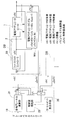
- the electric brake system includes a plurality of electric brake devices DB, a power supply device 3, and a host ECU 18.
- Each electric brake device DB includes an electric actuator 1 and a control device 2. First, the electric actuator 1 will be described.
- the electric actuator 1 includes an electric motor 4, a speed reduction mechanism 5 that decelerates the rotation of the electric motor 4, a linear motion mechanism (conversion mechanism) 6, and a parking brake mechanism 7 that is a parking brake. And a brake rotor 8 and a brake lining (which is a friction member and also includes a brake pad) 9.
- the electric motor 4, the speed reduction mechanism 5, and the linear motion mechanism 6 are incorporated in, for example, a housing not shown.
- the electric motor 4 is composed of a three-phase synchronous motor or the like.
- the reduction mechanism 5 is a mechanism that reduces and transmits the rotation of the electric motor 4 to a tertiary gear 11 fixed to the rotary shaft 10, and includes a primary gear 12, an intermediate gear 13, and a tertiary gear 11.
- the speed reduction mechanism 5 decelerates the rotation of the primary gear 12 attached to the rotor shaft 4 a of the electric motor 4 by the intermediate gear 13 and is fixed to the end of the rotation shaft 10. Can be communicated to.
- the linear motion mechanism 6 which is a brake lining operation means (friction member operation means), converts the rotational motion output from the speed reduction mechanism 5 into the linear motion of the linear motion portion 14 by the feed screw mechanism and This is a mechanism for abutting or separating the brake lining 9.
- the linear motion part 14 is supported so as to be free of rotation and movable in the axial direction indicated by the arrow A1.
- a brake lining 9 is provided on the outboard side end of the linear motion portion 14.
- the outboard side is a state where the electric brake device DB is mounted on the vehicle, the outside of the vehicle is called the outboard side, and the center side of the vehicle is called the inboard side.
- FIG. 3 is a diagram schematically showing the parking brake mechanism in plan view.
- a plurality (six in this example) of locking holes 17 are formed on the end face of the intermediate gear 13 on the outboard side at regular intervals in the circumferential direction.
- Each locking hole 17 is formed in a long hole shape extending along the circumferential direction.
- the lock member 15 can be locked in any one of the locking holes 17.
- a linear solenoid is applied as the parking brake actuator 16 (FIG. 2).
- the locking member (solenoid pin) 15 is advanced by the parking brake actuator 16 (FIG. 2) and is engaged by being fitted into the bottomed cylindrical hole portion 17a of the engagement hole 17 formed in the intermediate gear 13,
- the parking lock state is established by prohibiting the rotation of the intermediate gear 13.
- a part or all of the lock member 15 is retracted to the parking brake actuator 16 (FIG. 2) and detached from the locking hole 17, thereby permitting the rotation of the intermediate gear 13 and bringing it into an unlocked state.
- the control device 2 of each electric brake device DB is supplied with one main power supply device 3 that supplies power to the control device 2 and the electric motor 4, and 1 is a high-order control means of each control device 2.
- Two host ECUs 18 are connected.
- an electric control unit that controls the entire vehicle is applied as the host ECU 18.
- the host ECU 18 outputs a braking force target value to each control device 2 of each electric brake device DB in accordance with, for example, the output of a sensor (not shown) that changes according to the amount of operation of a brake pedal (not shown).
- the distribution ratio of the braking force target value to each electric brake device DB may be, for example, a fixed value, and is based on information on in-vehicle sensors such as an acceleration sensor and vehicle motion and posture estimated from specifications of the mounted vehicle. It may be a variable value.
- Each control device 2 includes a calculator 19, a motor driver 20, power supply switching means 21, and a standby power supply device 22.
- the calculator 19 is a control calculation means 23 for controlling the brake force of the electric brake device DB to follow the brake force target value from the sensing information of the electric actuator 1 and information such as the brake force target value.
- the computing unit 19 may be composed of a processor such as a microcomputer or a hardware module such as an ASIC. That is, the control calculation unit 23, the diagnosis unit 24, and the operation control unit 25 are realized by executing a process described later by executing a software program with a processor, or by executing with a hardware module.
- the sensing information of the electric motor 4 in the electric actuator 1 includes a motor current value detected from the detection means (means for detecting current) 26, a motor angle estimated from the rotation angle estimation means 27, and the like.
- the detection means 26 may be, for example, a current sensor, and may estimate a motor current value from motor specifications such as an inductance value and a resistance value measured in advance and a motor voltage.
- the rotation angle estimating means 27 may be, for example, an angle sensor such as a magnetic encoder or a resolver, and may estimate the motor angle from the motor specifications and the motor voltage using a physical equation.
- the brake force of the electric brake device DB is estimated by the brake force estimating means 28.
- the brake force estimating means 28 is a means for estimating the brake force actually generated from the detected value obtained by sensing the influence of the electric brake device DB itself or the wheels generated by the operation of the electric brake device DB. . And this brake estimation means 28 can estimate the braking force which generate
- the brake force estimating means 28 may be constituted by, for example, a load sensor that detects the load of the electric actuator 1, and estimates the brake force from information such as a wheel speed sensor and an acceleration sensor of a vehicle equipped with the electric brake system. Alternatively, the braking force may be estimated from the characteristics of the electric actuator 1 and the sensing information of the electric motor 4 described above.
- a magnetic sensor is used as the load sensor.
- a load sensor including a magnetic sensor magnetically detects the reaction force of the braking force as an axial displacement amount.
- the brake force estimating means 28 sets the relationship between the reaction force of the brake force and the sensor output in advance through experiments or the like, so that the brake force is calculated based on the sensor output of the load sensor. Can be estimated.
- an optical type sensor other than the magnetic type, an eddy current type, or a capacitance type sensor can be applied.
- the motor driver 20 converts the DC power of the power supply device 3 into three-phase AC power used for driving the electric motor 4.
- the motor driver 20 may be, for example, a half bridge circuit using a field effect transistor (abbreviated as FET), a snubber capacitor, or the like.
- the standby power supply 22 is used when the power supply 3 is abnormal, and is, for example, a small battery or a capacitor.
- the diagnosis unit 24 of the arithmetic unit 19 includes a power supply diagnosis unit that determines whether there is an abnormality in the power supply from the power supply device 3.
- the power diagnosis unit determines not only an abnormality of the power supply device itself but also an abnormality such as disconnection of the power supply harness extending from the power supply device 3.
- the power supply switching means 21 is composed of, for example, a switching element, and switches to power supply by the standby power supply 22 when it is determined by the power supply diagnosis function of the diagnosis means 24 that there is an abnormality in the power supply from the power supply 3.
- FIG. 4 is a block diagram illustrating an example in which a control amount complementing unit 29 is provided in the host ECU 18 in the electric brake system.
- the control calculation means 23 (FIG. 1) of the calculator 19 in each control device 2 performs follow-up control in which the brake force is fed back to the brake force target value given from the host ECU 18 by the feedback controller 30.
- FIG. 4 an example of a series output feedback compensator is shown, but state feedback control or nonlinear switching control may be used.
- the control calculation means 23 (FIG. 1) of the calculator 19 also calculates the difference in brake force estimated by the brake force estimation means 28 with respect to the calculation result of the state transition model Md (state transition equation), that is, the control amount error. It also has a function as a control amount error estimator that outputs ⁇ y.
- the control amount error includes the braking force of the electric brake device DB in which the function deterioration is detected by the diagnosis unit 24 (FIG. 1), that is, the brake force estimated by the brake estimation unit, and the electric brake device DB in the case where the function deterioration is not detected. It is the difference with the braking force.
- the diagnostic means 24 (FIG. 1) of the computing unit 19 detects the functional degradation as described later.
- the control amount error ⁇ y may occur due to an influence within a slight error range such as a dimensional tolerance of the linear motion mechanism 6 or the electric motor 4 or assembly accuracy.
- the diagnostic means 24 (FIG. 1) may use a dead band, a filter, or the like in order to remove the influence within such an error range.
- the state transition model Md includes a model calculation value x ′ (k) of the state amount x (k) including the motor rotation angle of the electric motor 4, and An operation amount u (k) including the voltage or current of the electric motor 4, a state transition matrix A including the electric actuator inertia of the electric actuator including the electric motor 4 and the linear motion mechanism 6, and a control amount y (k including the braking force).
- the host ECU 18 includes each wheel brake force calculation unit 31 that calculates a brake force target value to be distributed to each electric brake device DB, and a control amount complementing unit 29.
- the control amount complementing unit 29 sets the braking force target value of the electric brake device DB other than the electric brake device DB in which the control amount error ⁇ y has occurred.
- a braking force corresponding to the control amount error ⁇ y is distributed and added.
- control amount complementing unit 29 first checks the control amount error ⁇ y of each electric brake device DB. Then, the control amount complementing unit 29 distributes and adds an addition value equal to the sum of the control amount errors ⁇ y of each electric brake device DB to the electric brake device DB in which the control amount error ⁇ y is smaller than a predetermined value. At that time, the distribution ratio of the brake force target value to each electric brake device DB may be equal.
- the predetermined value is determined, for example, by a result of a test or simulation.
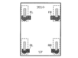
- FIG. 5 is a diagram showing a plan view of an electric brake system in which a plurality of electric brake devices are mounted on a vehicle
- FIG. 6 is a diagram showing a decrease in function of some electric brake devices in the electric brake system according to the present embodiment. It is a figure showing the relationship between time and braking force when it occurs. As shown in FIGS.
- the electric brake device RL disposed on the left rear wheel of the vehicle has a reduced function, and each brake force target value r FR , r FL , r RR , r RL
- operation examples that do not follow the braking force of the electric brake devices FR, FL, RR, and RL for the right front wheel, the left front wheel, the right rear wheel, and the left rear wheel, respectively, are shown.
- the other electric brake devices FR, FL, RR so as to complement and cancel out the control amount error ⁇ y RL generated in the electric brake device RL for the left rear wheel by the control amount complementing unit 29 (FIG. 4). Operates with a larger braking force than the respective braking force target values r FR , r FL , r RR .
- the function deterioration of the electric brake device DB is detected, and the brake force corresponding to the control amount error is added to the brake force target value of the normal electric brake device DB.
- the reduced braking force can be supplemented by the entire electric brake system. Therefore, a desired braking force can be generated even if a functional deterioration occurs in a part of the electric brake system.
- the main power supply device 3 supplies power to the control device 2 and the electric motor 4 respectively.
- the diagnosis unit 24 determines that there is an abnormality in the power supply from the power supply device 3 due to, for example, disconnection of the power supply harness
- the power supply switching unit 21 sends power from the main power supply device 3 to the standby power supply 22. Switch to supply. Therefore, redundancy of the entire electric brake system can be achieved.
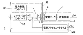
- FIG. 7 is a block diagram showing an electric brake system according to the second embodiment. This figure shows a configuration for limiting the power supplied to the electric motor when switching to the standby power supply.
- the power supply switching means 21 switches the power supply 3 (FIG. 1) to the power supply by the standby power supply 22 (FIG. 1)
- Power limiting means 32 is provided.
- a power limiting means 32 is provided in the computing unit 19 (FIG. 1).
- the power limiting unit 32 includes a power limiting controller 33 and a limiter circuit 34.
- the limiter circuit 34 can be switched between an active state and an inactive state by a signal from the power limit controller 33, and is always in an inactive state.
- the diagnosis unit 24 detects an abnormality in the power supply device 3 (FIG. 1) from the voltage change of the power supply device 3 (FIG. 1) and the result is received by the power limit controller 33, the power limit controller 33
- the circuit 34 is activated, and the output voltage is suppressed below the set voltage. Therefore, the power supplied to the electric motor 4 is limited.
- the power limit controller 33 may be configured to receive information from the host ECU 18 (FIG. 1) that an abnormality has occurred in the power supply device 3 (FIG. 1).
- the power limiting means 32 limits the power supplied to the electric motor 4 when the power supply device 3 (FIG. 1) is switched to the power supply by the standby power supply device 22 (FIG. 1).
- Overall redundancy can be achieved.
- the power consumption can be reduced, and the power consumption of the vehicle can be improved.
- the control amount error estimation unit controls the control amount error that is the difference between the braking force of the electric brake device that is power limited and the braking force of the electric brake device that is not power limited. Therefore, fine control can be performed.
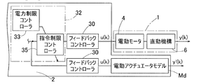
- FIG. 8 is a block diagram of the electric brake system according to the third embodiment. This figure shows a configuration for reducing power consumption in an electric brake system.
- the power limiting unit 32 in this example includes a power limiting controller 33 and a command limiting controller 35.
- the diagnosis unit 24 detects an abnormality of the power supply device 3 (FIG. 1) and the power limit controller 33 receives the result, the power limit controller 33 instructs the command limit controller 35 of the operating frequency of the electric brake device DB. Decrease or limit operation on the positive efficiency line. Thereby, power consumption can be reduced.
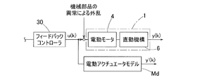
- FIG. 9 is a block diagram of an electric brake system according to the fourth embodiment.
- This figure is a block diagram showing a configuration corresponding to a case where a functional deterioration occurs due to an abnormality of a mechanical part of the electric brake device.
- the mechanical parts include bearings and gears in an electric brake device.
- the sliding resistance d increases due to such an abnormality of the machine part, and a control amount error occurs as an error of the motor torque.
- the control amount complementing unit 29 FIG. 4 adds the control amount error to the brake force target value of a normal electric brake device. Therefore, the braking force for the reduced function can be supplemented by the entire electric brake system.
- control amount complementing unit 29 is provided in the host ECU 18, but is not limited to this example.
- the control amount complementing unit 29 ⁇ / b> A may be provided in the control device 2 of each electric brake device DB.
- each control amount complementing unit 29A cooperates to calculate the sum of the control amount errors ⁇ y.
- a yaw moment calculating means 36 (FIG. 4) for obtaining a yaw moment generated in the vehicle is provided, and the control amount complementing unit 29 sets the brake force target value to the control amount error ⁇ y.
- the control amount complementing unit 29 determines the braking force addition value so that the yaw moment detected by the yaw moment calculating means 36 (FIG. 4) is not more than a predetermined value. Also good. In this case, even if a functional deterioration occurs in a part of the electric brake system, the braking force corresponding to the reduced function can be supplemented by the entire electric brake system, and the running stability of the vehicle can be improved.
- Either the left or right two wheels may be an electric brake device, and the rest may be a hydraulic brake device.
- the host ECU may be a VCU of a vehicle equipped with an electric brake system.
- the power supply device may be a low voltage battery or a DC / DC converter connected to the high voltage battery.
- the electric motor 4 may be, for example, a brushless DC motor or a DC motor using a brush, a slip ring, or the like.
- the linear motion mechanism may be a planetary roller screw, a ball ramp, or the like.
- the vehicle may be an electric vehicle in which driving wheels are driven by a motor, or a hybrid vehicle in which one of the front and rear wheels is driven by an engine and the other is driven by a motor. Further, an engine vehicle that drives a drive wheel only by an engine may be applied to the vehicle.
- the brake type may be a disc brake type or a drum brake type.
- Control device 4 Electric motor 6 .
- Linear motion mechanism (friction member operation means) 8 ...
- Brake rotor 9 ... Friction member 23 .
- Control calculation means (control amount error estimation unit) 29 ...
- Control amount complementing unit DB Electric brake device
Landscapes
- Engineering & Computer Science (AREA)
- Transportation (AREA)
- Mechanical Engineering (AREA)
- Braking Systems And Boosters (AREA)
- Valves And Accessory Devices For Braking Systems (AREA)
Abstract
電動ブレーキシステムの一部の機能低下時に電動ブレーキシステム全体でブレーキ力を補完することができる電動ブレーキシステムを提供する。この電動ブレーキシステムは、各電動ブレーキ装置(DB)の機能低下をそれぞれ検出する診断手段(24)と、診断手段(24)で機能低下が検出された電動ブレーキ装置(DB)のブレーキ力推定手段(28)で推定されたブレーキ力と、診断手段(24)で機能低下が検出されない電動ブレーキ装置(DB)のブレーキ力推定手段(28)で推定されたブレーキ力との差である制御量誤差を推定する制御演算手段(23)と、制御演算手段(23)により前記制御量誤差が発生したと推定されたとき、前記制御量誤差が発生した電動ブレーキ装置以外の電動ブレーキ装置(DB)のブレーキ力目標値に、前記制御量誤差に相当するブレーキ力を加算する制御量補完部(29)とを設けた。
Description
本出願は、2014年9月25日出願の特願2014-195093および2015年9月7日出願の特願2015-175334の優先権を主張するものであり、それらの全体を参照により本願の一部をなすものとして引用する。
この発明は、電動ブレーキシステムに関し、この電動ブレーキシステムの一部の機能低下時に電動ブレーキシステム全体でブレーキ力を補完する技術に関する。
電動ブレーキ装置として、以下の技術が提案されている。
1.遊星ローラねじ機構を使用した電動式直動アクチュエータ(特許文献1)。
2.ブレーキペダルを踏み込むことで、モータの回転運動を直動機構を介して直線運動に変換して、ブレーキパッドをブレーキディスクに押圧接触させて制動力を付加する技術(特許文献2)。
1.遊星ローラねじ機構を使用した電動式直動アクチュエータ(特許文献1)。
2.ブレーキペダルを踏み込むことで、モータの回転運動を直動機構を介して直線運動に変換して、ブレーキパッドをブレーキディスクに押圧接触させて制動力を付加する技術(特許文献2)。
特許文献1,2のような電動ブレーキ装置において、電動アクチュエータの機械部品の異常や、電源系統の異常などにより、電動ブレーキ装置の機能低下が発生する場合がある。この場合、所望のブレーキ力を発生することができないことがある。
この発明の目的は、電動ブレーキシステムの一部の機能低下時に電動ブレーキシステム全体でブレーキ力を補完することができる電動ブレーキシステムを提供することである。
以下、便宜上理解を容易にするために、実施形態の符号を参照して説明する。
この発明の一構成に係る電動ブレーキシステムは、複数の電動ブレーキ装置DBを備えた電動ブレーキシステムであって、各電動ブレーキ装置DBが、ブレーキロータ8と、このブレーキロータ8に接触させる摩擦部材9と、この摩擦部材9を前記ブレーキロータ8に接触させる摩擦部材操作手段6と、この摩擦部材操作手段6を駆動する電動モータ4と、前記摩擦部材9を前記ブレーキロータ8に押し付けることにより発生するブレーキ力の推定値を求めるブレーキ力推定手段28と、前記電動モータ4を制御して、前記発生するブレーキ力をブレーキ力目標値に対して追従制御させる制御装置2とを有し、当該電動ブレーキシステムが、さらに、各電動ブレーキ装置DBについて、その前記ブレーキ力推定手段28で推定されたブレーキ力と、機能低下がない場合のブレーキ力との差である制御量誤差を推定する制御量誤差推定部23と、
この制御量誤差推定部23により前記制御量誤差が発生したと推定されたとき、前記制御量誤差が発生した電動ブレーキ装置以外の電動ブレーキ装置DBのブレーキ力目標値に、前記制御量誤差に相当するブレーキ力を分配して加算する制御量補完部29と、
を備える。
この制御量誤差推定部23により前記制御量誤差が発生したと推定されたとき、前記制御量誤差が発生した電動ブレーキ装置以外の電動ブレーキ装置DBのブレーキ力目標値に、前記制御量誤差に相当するブレーキ力を分配して加算する制御量補完部29と、
を備える。
なお、前記「摩擦部材」は、ブレーキライニングやブレーキパッドなどを含む概念である。
前記機能低下とは、電動ブレーキ装置DBの例えば軸受等の機械部品に異常が生じたり、電動ブレーキ装置DBの電源系統に異常が生じたりすること等である。
前記機能低下とは、電動ブレーキ装置DBの例えば軸受等の機械部品に異常が生じたり、電動ブレーキ装置DBの電源系統に異常が生じたりすること等である。
この構成によると、制御量誤差推定部23により制御量誤差が発生したと推定されたとき、制御量補完部29は、制御量誤差が発生した電動ブレーキ装置以外の電動ブレーキ装置DB、つまり正常な電動ブレーキ装置DBのブレーキ力目標値に、前記制御量誤差に相当するブレーキ力を分配して加算する。
このように電動ブレーキ装置DBの機能低下を検出し、正常な電動ブレーキ装置DBのブレーキ力目標値に、前記制御量誤差に相当するブレーキ力を分配して加算することで、機能低下によって発揮できないブレーキ力を電動ブレーキシステム全体で補完することができる。したがって、電動ブレーキシステムの一部に機能低下が発生しても、車両全体として所望のブレーキ力を発生することができる。
さらに、前記各電動ブレーキ装置の機能低下をそれぞれ検出する複数の診断手段を備え、
前記制御量誤差推定部が、前記診断手段で機能低下が検出された電動ブレーキ装置の前記ブレーキ推定手段で推定されたブレーキ力と、前記診断手段で機能低下が検出されない電動ブレーキ装置の前記ブレーキ力推定手段で推定されたブレーキ力との差を推定しても良い。
前記制御量誤差推定部が、前記診断手段で機能低下が検出された電動ブレーキ装置の前記ブレーキ推定手段で推定されたブレーキ力と、前記診断手段で機能低下が検出されない電動ブレーキ装置の前記ブレーキ力推定手段で推定されたブレーキ力との差を推定しても良い。
前記制御量誤差推定部23が、
前記電動モータのモータ回転角を含む状態量と、
前記電動モータ4の電圧または電流を含む操作量と、
前記電動モータ4および前記摩擦部材操作手段6を含む電動アクチュエータの電動アクチュエータ慣性を含む状態遷移行列と、
ブレーキ力を含む制御量との関係を表す状態遷移式Mdを、機能低下がない場合の前記ブレーキ力を取得するために用いても良い。
この場合、制御量誤差を精度良く求めることができる。
前記電動モータのモータ回転角を含む状態量と、
前記電動モータ4の電圧または電流を含む操作量と、
前記電動モータ4および前記摩擦部材操作手段6を含む電動アクチュエータの電動アクチュエータ慣性を含む状態遷移行列と、
ブレーキ力を含む制御量との関係を表す状態遷移式Mdを、機能低下がない場合の前記ブレーキ力を取得するために用いても良い。
この場合、制御量誤差を精度良く求めることができる。
さらに、前記複数の電気ブレーキ装置の前記制御装置2それぞれおよび前記電動モータ4それぞれに電力を供給する主たる電源装置3と、この電源装置3の異常時に使用される予備電源装置22とを備え、前記診断手段24は、前記電源装置3からの電力供給の異常の有無を判断する電源診断部を有し、当該電動ブレーキシステムが、さらに、前記電源診断部により前記電源装置3からの電力供給に異常有りと判断したとき、前記予備電源装置22による電力供給に切り替える電力供給切替手段21を備えても良い。
前記予備電源装置22は、例えば、小型バッテリやキャパシタ等であっても良い。
前記予備電源装置22は、例えば、小型バッテリやキャパシタ等であっても良い。
この構成によると、通常時においては、主たる電源装置3が制御装置2および電動モータ4にそれぞれ電力を供給する。診断手段24が、例えば、電力供給ハーネスの断線等に起因して電源装置3からの電力供給に異常有りと判断したとき、電力供給切替手段21は、主たる電源装置3から予備電源装置22による電力供給に切り替える。したがって、電動ブレーキシステム全体の冗長化を図ることができる。
さらに、前記電力供給切替手段21により、前記電源装置3から前記予備電源装置22による電力供給に切り替えられたとき、前記電動モータ4に供給する電力を制限する電力制限手段32を備え、前記制御量誤差推定部23が、前記電力制限手段32で電力制限される電動ブレーキ装置DBの前記ブレーキ力推定手段28で推定されたブレーキ力と、前記電力制限手段32で電力制限されない電動ブレーキ装置DBの前記ブレーキ力推定手段28で推定されたブレーキ力との差である制御量誤差を推定するものとしても良い。
この場合、電力制限手段32は、電源装置3から予備電源装置22による電力供給に切り替えられたとき、電動モータ4に供給する電力を制限することで、電動ブレーキシステム全体の冗長化を図れる。また消費電力を低減でき、車両の電費の向上を図れる。このように冗長化および電費向上を図ったうえで、制御量誤差推定部23は、電力制限される電動ブレーキ装置DBのブレーキ力と、電力制限されない電動ブレーキ装置DBのブレーキ力との差である制御量誤差を推定するため、木目細かな制御を行うことができる。
さらに、この電動ブレーキシステムを搭載する車両に発生するヨーモーメントを求めるヨーモーメント算出手段36を備え、前記制御量補完部29により、前記ブレーキ力目標値に前記制御量誤差に相当するブレーキ力を加算するとき、前記制御量補完部29は、前記ヨーモーメント算出手段36で検出されるヨーモーメントが定められた値以下となるようにブレーキ力加算値を決定するようにしても良い。
前記定められた値は、例えば、試験やシミュレーション等の結果により定められる。
この場合、電動ブレーキシステムの一部に機能低下が発生しても、機能低下分を電動ブレーキシステム全体でブレーキ力を補完することができるうえ車両の走行安定性を高めることができる。
この場合、電動ブレーキシステムの一部に機能低下が発生しても、機能低下分を電動ブレーキシステム全体でブレーキ力を補完することができるうえ車両の走行安定性を高めることができる。
請求の範囲および/または明細書および/または図面に開示された少なくとも2つの構成のどのような組合せも、本発明に含まれる。特に、請求の範囲の各請求項の2つ以上のどのような組合せも、本発明に含まれる。
この発明は、添付の図面を参考にした以下の好適な実施形態の説明から、より明瞭に理解されるであろう。しかしながら、実施形態および図面は単なる図示および説明のためのものであり、この発明の範囲を定めるために利用されるべきものではない。この発明の範囲は添付の請求の範囲によって定まる。添付図面において、複数の図面における同一の符号は、同一または相当する部分を示す。
第1の実施形態に係る電動ブレーキシステムを概略的に示すブロック図である。
図1の電動ブレーキシステムにおける電動ブレーキ装置を概略的に示す図である。
図2の電動ブレーキ装置のパーキングブレーキ機構を平面視で概略的に示す図である。
図1の電動ブレーキシステムの制御系のブロック図である。
各実施形態の電動ブレーキシステムを平面視で示す図であって、複数の電動ブレーキ装置を車両に搭載した構成を示す図である。
図1の電動ブレーキシステムにおいて、一部の電動ブレーキ装置に機能低下が発生した場合における、時間とブレーキ力と関係を表すグラフである。
第2の実施形態に係る電動ブレーキシステムの電動ブレーキ装置における制御ブロックを示す図であって、予備電源装置への切替時に電動モータに供給する電力を制限する構成を示すブロック図である。
第3の実施形態に係る電動ブレーキシステムの電動ブレーキ装置における制御ブロックを示す図であって、消費電力を低減する構成を示すブロック図である。
第4の実施形態に係る電動ブレーキシステムの電動ブレーキ装置における制御ブロックを示す図であって、電動ブレーキ装置の機械部品の異常による機能低下が発生した場合に対応する構成を示すブロック図である。
第5の実施形態に係る電動ブレーキシステムの制御系のブロック図である。
第1の実施形態に係る電動ブレーキシステムを図1ないし図6と共に説明する。
図1に示すように、この電動ブレーキシステムは、複数の電動ブレーキ装置DBと、電源装置3と、上位ECU18とを有する。各電動ブレーキ装置DBは、電動アクチュエータ1と、制御装置2とを有する。先ず、電動アクチュエータ1について説明する。
図1に示すように、この電動ブレーキシステムは、複数の電動ブレーキ装置DBと、電源装置3と、上位ECU18とを有する。各電動ブレーキ装置DBは、電動アクチュエータ1と、制御装置2とを有する。先ず、電動アクチュエータ1について説明する。
図2に示すように、電動アクチュエータ1は、電動モータ4と、この電動モータ4の回転を減速する減速機構5と、直動機構(変換機構)6と、駐車ブレーキであるパーキングブレーキ機構7と、ブレーキロータ8と、ブレーキライニング(摩擦部材であって、ブレーキパッドも含む)9とを有する。前記電動モータ4、減速機構5、および直動機構6は、例えば、図示外のハウジング等に組込まれる。
電動モータ4は3相の同期モータ等からなる。減速機構5は、電動モータ4の回転を、回転軸10に固定された3次歯車11に減速して伝える機構であり、1次歯車12、中間歯車13、および3次歯車11を含む。この例では、減速機構5は、電動モータ4のロータ軸4aに取り付けられた1次歯車12の回転を、中間歯車13により減速して、回転軸10の端部に固定された3次歯車11に伝達可能としている。
ブレーキライニング操作手段(摩擦部材操作手段)である直動機構6は、減速機構5で出力される回転運動を送りねじ機構により直動部14の直線運動に変換して、ブレーキロータ8に対してブレーキライニング9を当接または離隔させる機構である。直動部14は、回り止めされ且つ矢符A1にて表記する軸方向に移動自在に支持されている。直動部14のアウトボード側端にブレーキライニング9が設けられる。電動モータ4の回転を減速機構5を介して直動機構6に伝達することで、回転運動が直線運動に変換され、それがブレーキライニング9の押圧力に変換されることによりブレーキ力を発生させる。なお、アウトボード側とは電動ブレーキ装置DBを車両に搭載した状態で、車両の外側をアウトボード側といい、車両の中央側をインボード側という。
図3は、パーキングブレーキ機構を平面視で概略示す図である。中間歯車13のアウトボード側端面には、複数(この例では6個)の係止孔17が円周方向一定間隔おきに形成される。各係止孔17は、円周方向に沿って延びる長孔形状にそれぞれ形成される。これら係止孔17のいずれか1つにロック部材15が係止可能に構成される。
パーキングブレーキ用アクチュエータ16(図2)として例えばリニアソレノイドが適用される。パーキングブレーキ用アクチュエータ16(図2)によりロック部材(ソレノイドピン)15を進出させて中間歯車13に形成された係止孔17の有底円筒孔部17aに嵌まり込ませることで係止し、中間歯車13の回転を禁止することで、パーキングロック状態にする。ロック部材15の一部または全部をパーキングブレーキ用アクチュエータ16(図2)に退避させて係止孔17から離脱させることで中間歯車13の回転を許容し、アンロック状態にする。
図1に示すように、各電動ブレーキ装置DBの制御装置2に、制御装置2および電動モータ4にそれぞれ電力を供給する1つの主たる電源装置3と、各制御装置2の上位制御手段である1つの上位ECU18とが接続されている。上位ECU18として、例えば、車両全般を制御する電気制御ユニットが適用される。上位ECU18は、例えば、図示外のブレーキペダルの操作量に応じて変化するセンサ(図示せず)の出力に応じて、各電動ブレーキ装置DBの制御装置2それぞれにブレーキ力目標値を出力する。各電動ブレーキ装置DBへのブレーキ力目標値の配分比率は、例えば、固定の値としても良く、加速度センサ等の車載センサ類の情報および搭載車両の諸元から推定する車両の運動や姿勢に基づく可変の値としても良い。
各制御装置2は、演算器19と、モータドライバ20と、電力供給切替手段21と、予備電源装置22とを有する。演算器19は、電動アクチュエータ1のセンシング情報および前記ブレーキ力目標値等の情報から、電動ブレーキ装置DBのブレーキ力を前記ブレーキ力目標値に対して追従制御するための制御演算手段23、前記情報から電動ブレーキ装置DBの機能低下を検出する診断手段24、および、周辺の各スイッチやモータドライバ20等の動作を制御する動作制御手段25を含む。前記演算器19は、マイクロコンピュータ等のプロセッサから構成されても良く、ASIC等のハードウェアモジュールから構成されても良い。すなわち、制御演算手段23、診断手段24および動作制御手段25は、後述する処理をソフトウェアプログラムをプロセッサで実行することによって、またはハードウェアモジュールで実行することによって実現される。
電動アクチュエータ1における電動モータ4のセンシング情報としては、検出手段(電流等を検出する手段)26から検出されるモータ電流値、および回転角推定手段27から推定されるモータ角度等が挙げられる。前記検出手段26は、例えば、電流センサであっても良く、予め測定したインダクタンス値や抵抗値等のモータ諸元およびモータ電圧からモータ電流値を推定しても良い。前記回転角推定手段27は、例えば、磁気エンコーダやレゾルバ等の角度センサであっても良く、前記モータ諸元およびモータ電圧から物理方程式を用いてモータ角度を推定しても良い。
電動ブレーキ装置DBのブレーキ力は、ブレーキ力推定手段28で推定される。なおブレーキ力推定手段28は、この電動ブレーキ装置DBの動作により生じる、この電動ブレーキ装置DB自体または車輪に生じる影響をセンシングした検出値から、実際に発生しているブレーキ力を推定する手段である。そして、このブレーキ推定手段28は、特に、電動ブレーキ装置DBに機能低下が生じても、その機能低下が生じた状態で発生するブレーキ力を推定できる。このブレーキ力推定手段28は、例えば、電動アクチュエータ1の荷重を検出する荷重センサから構成されても良く、本電動ブレーキシステムを搭載する車両の車輪速センサや加速度センサ等の情報からブレーキ力を推定しても良く、電動アクチュエータ1の特性および前述の電動モータ4のセンシング情報からブレーキ力を推定しても良い。
前記荷重センサは、例えば、磁気式のセンサが適用される。図2に示すように、ブレーキライニング9がブレーキロータ8を押圧するとき、直動部14にインボード側への反力が作用する。磁気式のセンサからなる荷重センサは、このブレーキ力の反力を軸方向の変位量として磁気的に検出する。図1に示すように、ブレーキ力推定手段28は、前記ブレーキ力の反力とセンサ出力との関係を実験等で予め設定しておくことにより、荷重センサのセンサ出力に基づいて、ブレーキ力を推定し得る。なお、荷重センサとして、磁気式以外の光学式、渦電流式、または静電容量式のセンサを適用することも可能である。
モータドライバ20は、電源装置3の直流電力を電動モータ4の駆動に用いる3相の交流電力に変換する。このモータドライバ20は、例えば、電界効果トランジスタ(Field effect transistor,略称FET)、スナバコンデンサ等を用いたハーフブリッジ回路であっても良い。
予備電源装置22は、電源装置3の異常時に使用されるものであり、例えば、小型バッテリやキャパシタ等である。演算器19の前記診断手段24は、電源装置3からの電力供給の異常の有無を判断する電源診断部を有する。この電源診断部は、電源装置自体の異常だけでなく、電源装置3から延びる電力供給ハーネスの断線等の異常も判断する。
電力供給切替手段21は、例えば、スイッチング素子から成り、診断手段24の電源診断機能により電源装置3からの電力供給に異常ありと判断したとき、予備電源装置22による電力供給に切り替える。
図4は、電動ブレーキシステムにおいて、上位ECU18に制御量補完部29を設けた例を示すブロック図である。各制御装置2における演算器19の制御演算手段23(図1)は、フィードバックコントローラ30により、上位ECU18から与えられるブレーキ力目標値に対してブレーキ力をフィードバックする追従制御を実施する。この実施形態においては、直列出力フィードバック補償器の例を示しているが、状態フィードバック制御や非線形切替制御を用いても良い。
演算器19の制御演算手段23(図1)は、また、状態遷移モデルMd(状態遷移式)の演算結果に対する、ブレーキ力推定手段28で推定されたブレーキ力の差、つまり制御量誤差を、Δyとして出力する制御量誤差推定部としての機能も有する。前記制御量誤差は、診断手段24(図1)で機能低下が検出された電動ブレーキ装置DBのブレーキ力つまりブレーキ推定手段で推定されたブレーキ力と、機能低下が検出されない場合の電動ブレーキ装置DBのブレーキ力との差である。
電動ブレーキ装置DBに何らかの機能低下が発生した場合、演算器19の診断手段24(図1)が後述するように前記機能低下を検出する。その際、例えば、直動機構6や電動モータ4の寸法公差や組立精度等の僅かな誤差範囲内の影響によっても、制御量誤差Δyが発生する可能性がある。診断手段24(図1)は、このような誤差範囲内の影響を除去するためにデッドバンドやフィルタ等を用いても良い。
制御量誤差推定部である制御演算手段23(図1)において、前記状態遷移モデルMdは、電動モータ4のモータ回転角を含む状態量x(k)のモデル演算値x´(k)と、電動モータ4の電圧または電流を含む操作量u(k)と、電動モータ4および直動機構6を含む電動アクチュエータの電動アクチュエータ慣性を含む状態遷移行列Aと、ブレーキ力を含む制御量y(k)とを有し、次のように表される。
x´(k)=A(k-1)x´(k-1)+B(k-1)u(k-1)
y´(k)=C(k)x´(k)
x´(k)=A(k-1)x´(k-1)+B(k-1)u(k-1)
y´(k)=C(k)x´(k)
上位ECU18は、各電動ブレーキ装置DBへ配分すべきブレーキ力目標値を演算する各輪ブレーキ力演算部31と、制御量補完部29とを有する。この制御量補完部29は、前記制御量誤差推定部により制御量誤差Δyが発生したと推定されたとき、制御量誤差Δyが発生した電動ブレーキ装置DB以外の電動ブレーキ装置DBのブレーキ力目標値に、前記制御量誤差Δyに相当するブレーキ力を分配して加算する。
具体的には、制御量補完部29は、まず、各電動ブレーキ装置DBの制御量誤差Δyをチェックする。そして、制御量補完部29は、制御量誤差Δyが所定値より小さい電動ブレーキ装置DBに対して、各電動ブレーキ装置DBの制御量誤差Δyの総和と等しい加算値を分配して加算する。その際、各電動ブレーキ装置DBへのブレーキ力目標値の分配比率は等配としても良い。前記所定値は、例えば、試験やシミュレーション等の結果により定められる。
図5は、複数の電動ブレーキ装置を車両に搭載した電動ブレーキシステムを平面視で示す図であり、図6は、本実施形態に係る電動ブレーキシステムにおいて、一部の電動ブレーキ装置に機能低下が発生した場合の時間とブレーキ力と関係を表す図である。図5および図6に示すように、ある時間において、車両の左後輪に配置された電動ブレーキ装置RLに機能低下が発生し、各ブレーキ力目標値rFR ,rFL ,rRR ,rRLに対し、それぞれ右前輪、左前輪、右後輪、左後輪の電動ブレーキ装置FR,FL,RR,RLのブレーキ力に追従しない動作例を示す。この場合、前述の制御量補完部29(図4)により、左後輪の電動ブレーキ装置RLに発生した制御量誤差ΔyRLを補完して打ち消すように、他の電動ブレーキ装置FR,FL,RRが各ブレーキ力目標値rFR ,rFL ,rRRからよりも大きいブレーキ力で動作する。
以上説明した電動ブレーキシステムによれば、電動ブレーキ装置DBの機能低下を検出し、正常な電動ブレーキ装置DBのブレーキ力目標値に、前記制御量誤差に相当するブレーキ力を加算することで、機能低下分のブレーキ力を電動ブレーキシステム全体で補完することができる。したがって、電動ブレーキシステムの一部に機能低下が発生しても、所望のブレーキ力を発生することができる。
通常時においては、主たる電源装置3が制御装置2および電動モータ4にそれぞれ電力を供給する。診断手段24が、例えば、電力供給ハーネスの断線等に起因して電源装置3からの電力供給に異常有りと判断したとき、電力供給切替手段21は、主たる電源装置3から予備電源装置22による電力供給に切り替える。したがって、電動ブレーキシステム全体の冗長化を図ることができる。
第2の実施形態について説明する。
以下の説明においては、各形態で先行する形態で説明している事項に対応している部分には同一の参照符を付し、重複する説明を略する。構成の一部のみを説明している場合、構成の他の部分は、特に記載のない限り先行して説明している形態と同様とする。同一の構成から同一の作用効果を奏する。実施の各形態で具体的に説明している部分の組合せばかりではなく、特に組合せに支障が生じなければ、実施の形態同士を部分的に組合せることも可能である。
以下の説明においては、各形態で先行する形態で説明している事項に対応している部分には同一の参照符を付し、重複する説明を略する。構成の一部のみを説明している場合、構成の他の部分は、特に記載のない限り先行して説明している形態と同様とする。同一の構成から同一の作用効果を奏する。実施の各形態で具体的に説明している部分の組合せばかりではなく、特に組合せに支障が生じなければ、実施の形態同士を部分的に組合せることも可能である。
図7は、第2実施形態に係る電動ブレーキシステムを示すブロック図である。この図は、予備電源装置への切替時に電動モータに供給する電力を制限する構成を示す。この例では、前記電力供給切替手段21(図1)により、電源装置3(図1)から予備電源装置22(図1)による電力供給に切り替えられたとき、電動モータ4に供給する電力を制限する電力制限手段32を設けている。
演算器19(図1)に電力制限手段32が設けられる。この電力制限手段32は、電力制限コントローラ33と、リミッタ回路34とを有する。リミッタ回路34は、電力制限コントローラ33からの信号により能動状態と非能動状態とに切換可能であり、常時は非能動状態とされる。電源装置3(図1)の電圧の変化等から電源装置3(図1)の異常を診断手段24が検出して、その結果を電力制限コントローラ33が受けると、この電力制限コントローラ33は、リミッタ回路34を能動状態とし、出力電圧を設定電圧以下に抑制させる。よって、電動モータ4に供給する電力を制限する。なお電力制限コントローラ33は、電源装置3(図1)に異常が発生したことを、上位ECU18(図1)から情報として受け取る仕様でも良い。
この場合、電力制限手段32は、電源装置3(図1)から予備電源装置22(図1)による電力供給に切り替えられたとき、電動モータ4に供給する電力を制限することで、電動ブレーキシステム全体の冗長化を図れる。また消費電力を低減でき、車両の電費の向上を図れる。このように冗長化および電費向上を図ったうえで、制御量誤差推定部は、電力制限される電動ブレーキ装置のブレーキ力と、電力制限されない電動ブレーキ装置のブレーキ力との差である制御量誤差を推定するため、木目細かな制御を行うことができる。
図8は、第3の実施形態に係る電動ブレーキシステムをブロック図である。この図は、電動ブレーキシステムにおいて、消費電力を低減する構成を示す。この例の電力制限手段32は、電力制限コントローラ33と、指令制限コントローラ35とを有する。電源装置3(図1)の異常を診断手段24が検出して、その結果を電力制限コントローラ33が受けると、電力制限コントローラ33は、指令制限コントローラ35に対し、電動ブレーキ装置DBの動作周波数の低下や、正効率線上での動作制限を行わせる。これにより消費電力を低減できる。その他、図7に示した第2の実施形態に係る電動ブレーキシステムと同様の効果を奏する。
図9は、第4の実施形態に係る電動ブレーキシステムをブロック図である。この図は、電動ブレーキ装置の機械部品の異常による機能低下が発生した場合に対応する構成を示すブロック図である。前記機械部品として、例えば、電動ブレーキ装置内の軸受や歯車等が挙げられる。このような機械部品の異常により摺動抵抗dが増加し、モータトルクの誤差として制御量誤差が発生する。
このような制御量誤差が発生した場合においても、制御量補完部29(図4)は、正常な電動ブレーキ装置のブレーキ力目標値に前記制御量誤差を加算する。したがって、機能低下分のブレーキ力を電動ブレーキシステム全体で補完することができる。
このような制御量誤差が発生した場合においても、制御量補完部29(図4)は、正常な電動ブレーキ装置のブレーキ力目標値に前記制御量誤差を加算する。したがって、機能低下分のブレーキ力を電動ブレーキシステム全体で補完することができる。
図4の例では、上位ECU18に制御量補完部29を設けたが、この例に限定されるものではない。例えば、図10に第5の実施形態に係る電動ブレーキシステムを示すように、各電動ブレーキ装置DBの制御装置2に、制御量補完部29Aを設けても良い。本実施形態によれば、各制御量補完部29Aが連携して制御量誤差Δyの総和を算出する。
4輪に電動ブレーキ装置を搭載した車両において、この車両に発生するヨーモーメントを求めるヨーモーメント算出手段36(図4)を設け、制御量補完部29により、ブレーキ力目標値に制御量誤差Δyに相当するブレーキ力を加算するとき、制御量補完部29は、前記ヨーモーメント算出手段36(図4)で検出されるヨーモーメントが定められた値以下となるようにブレーキ力加算値を決定しても良い。この場合、電動ブレーキシステムの一部に機能低下が発生しても、機能低下分のブレーキ力を電動ブレーキシステム全体で補完することができるうえ車両の走行安定性を高めることができる。
前後いずれかの左右2輪が電動ブレーキ装置で、残りは油圧式ブレーキ装置であっても良い。上位ECUは電動ブレーキシステム搭載車両のVCUであっても良い。電源装置は、低圧バッテリや、高圧バッテリに接続されたDC/DCコンバータであっても良い。
電動モータ4は、例えば、ブラシレスDCモータであっても良く、ブラシやスリップリング等を用いたDCモータであっても良い。
直動機構は、遊星ローラねじ、ボールランプ等の機構であっても良い。
電動モータ4は、例えば、ブラシレスDCモータであっても良く、ブラシやスリップリング等を用いたDCモータであっても良い。
直動機構は、遊星ローラねじ、ボールランプ等の機構であっても良い。
車両は、駆動輪をモータで駆動する電気自動車であっても良いし、前後輪の一方をエンジンで駆動し、他方をモータで駆動するハイブリッド自動車あっても良い。また車両に、エンジンのみで駆動輪を駆動するエンジン車を適用しても良い。ブレーキのタイプはディスクブレーキタイプであってもドラムブレーキタイプであってもよい。
以上のとおり、図面を参照しながら好適な実施形態を説明したが、当業者であれば、本件明細書を見て、自明な範囲内で種々の変更および修正を容易に想定するであろう。したがって、そのような変更および修正は、請求の範囲から定まる発明の範囲内のものと解釈される。
2…制御装置
4…電動モータ
6…直動機構(摩擦部材操作手段)
8…ブレーキロータ
9…摩擦部材
23…制御演算手段(制御量誤差推定部)
29…制御量補完部DB…電動ブレーキ装置
4…電動モータ
6…直動機構(摩擦部材操作手段)
8…ブレーキロータ
9…摩擦部材
23…制御演算手段(制御量誤差推定部)
29…制御量補完部DB…電動ブレーキ装置
Claims (6)
- 複数の電動ブレーキ装置を備えた電動ブレーキシステムであって、
各電動ブレーキ装置が、
ブレーキロータと、
このブレーキロータに接触させる摩擦部材と、
この摩擦部材を前記ブレーキロータに接触させる摩擦部材操作手段と、
この摩擦部材操作手段を駆動する電動モータと、
前記摩擦部材を前記ブレーキロータに押し付けることにより発生するブレーキ力の推定値を求めるブレーキ力推定手段と、
前記電動モータを制御して、前記発生するブレーキ力をブレーキ力目標値に対して追従制御させる制御装置とを有し、
当該電動ブレーキシステムが、さらに、各電動ブレーキ装置について、その前記ブレーキ力推定手段で推定されたブレーキ力と、機能低下がない場合のブレーキ力との差である制御量誤差を推定する制御量誤差推定部と、
この制御量誤差推定部により前記制御量誤差が発生したと推定されたとき、前記制御量誤差が発生した電動ブレーキ装置以外の電動ブレーキ装置のブレーキ力目標値に、前記制御量誤差に相当するブレーキ力を分配して加算する制御量補完部と、
を備えた、電動ブレーキシステム。 - 請求項1に記載の電動ブレーキシステムにおいて、さらに、
前記各電動ブレーキ装置の機能低下をそれぞれ検出する複数の診断手段を備え、
前記制御量誤差推定部が、前記診断手段で機能低下が検出された電動ブレーキ装置の前記ブレーキ推定手段で推定されたブレーキ力と、前記診断手段で機能低下が検出されない電動ブレーキ装置の前記ブレーキ力推定手段で推定されたブレーキ力との差を推定する、電動ブレーキシステム。 - 請求項1または2に記載の電動ブレーキシステムにおいて、
前記制御量誤差推定部が、
前記電動モータのモータ回転角を含む状態量と、
前記電動モータの電圧または電流を含む操作量と、
前記電動モータおよび前記摩擦部材操作手段を含む電動アクチュエータの電動アクチュエータ慣性を含む状態遷移行列と、
ブレーキ力を含む制御量との関係を表す状態遷移式を、機能低下がない場合の前記ブレーキ力を取得するために用いる、電動ブレーキシステム。 - 請求項2または請求項2に従属する請求項3に記載に電動ブレーキシステムにおいて、さらに、
前記複数の電気ブレーキ装置の前記制御装置それぞれおよび前記電動モータそれぞれに電力を供給する主たる電源装置と、
この電源装置の異常時に使用される予備電源装置とを備え、
前記診断手段は、
前記電源装置からの電力供給の異常の有無を判断する電源診断部を有し、
当該電動ブレーキシステムが、さらに、
前記電源診断部により前記電源装置からの電力供給に異常有りと判断したとき、前記予備電源装置による電力供給に切り替える電力供給切替手段を備えた、電動ブレーキシステム。 - 請求項4に記載の電動ブレーキシステムにおいて、さらに、
前記電力供給切替手段により、前記電源装置から前記予備電源装置による電力供給に切り替えられたとき、前記電動モータに供給する電力を制限する電力制限手段を備え、
前記制御量誤差推定部が、前記電力制限手段で電力制限される電動ブレーキ装置の前記ブレーキ力推定手段で推定されたブレーキ力と、前記電力制限手段で電力制限されない電動ブレーキ装置の前記ブレーキ力推定手段で推定されたブレーキ力との差である制御量誤差を推定する、電動ブレーキシステム。 - 請求項1ないし請求項5のいずれか1項に記載の電動ブレーキシステムにおいて、さらに、
この電動ブレーキシステムを搭載する車両に発生するヨーモーメントを求めるヨーモーメント算出手段を備え、
前記制御量補完部により、前記ブレーキ力目標値に前記制御量誤差に相当するブレーキ力を加算するとき、前記制御量補完部は、前記ヨーモーメント算出手段で検出されるヨーモーメントが定められた値以下となるようにブレーキ力加算値を決定する電動ブレーキシステム。
Priority Applications (3)
| Application Number | Priority Date | Filing Date | Title |
|---|---|---|---|
| EP15844226.9A EP3199416B1 (en) | 2014-09-25 | 2015-09-14 | Electric brake system |
| CN201580051363.0A CN106715216B (zh) | 2014-09-25 | 2015-09-14 | 电动制动系统 |
| US15/457,120 US10576952B2 (en) | 2014-09-25 | 2017-03-13 | Electric brake system |
Applications Claiming Priority (4)
| Application Number | Priority Date | Filing Date | Title |
|---|---|---|---|
| JP2014195093 | 2014-09-25 | ||
| JP2014-195093 | 2014-09-25 | ||
| JP2015175334A JP6584877B2 (ja) | 2014-09-25 | 2015-09-07 | 電動ブレーキシステム |
| JP2015-175334 | 2015-09-07 |
Related Child Applications (1)
| Application Number | Title | Priority Date | Filing Date |
|---|---|---|---|
| US15/457,120 Continuation US10576952B2 (en) | 2014-09-25 | 2017-03-13 | Electric brake system |
Publications (1)
| Publication Number | Publication Date |
|---|---|
| WO2016047481A1 true WO2016047481A1 (ja) | 2016-03-31 |
Family
ID=55581008
Family Applications (1)
| Application Number | Title | Priority Date | Filing Date |
|---|---|---|---|
| PCT/JP2015/075987 WO2016047481A1 (ja) | 2014-09-25 | 2015-09-14 | 電動ブレーキシステム |
Country Status (1)
| Country | Link |
|---|---|
| WO (1) | WO2016047481A1 (ja) |
Cited By (1)
| Publication number | Priority date | Publication date | Assignee | Title |
|---|---|---|---|---|
| WO2018052068A1 (ja) * | 2016-09-15 | 2018-03-22 | Ntn株式会社 | 電動ブレーキ装置 |
Citations (2)
| Publication number | Priority date | Publication date | Assignee | Title |
|---|---|---|---|---|
| JPH11171006A (ja) * | 1997-12-11 | 1999-06-29 | Toyota Motor Corp | 電動式ブレーキ装置 |
| JP2007137182A (ja) * | 2005-11-16 | 2007-06-07 | Hitachi Ltd | 電動ブレーキシステム及びそれに用いる電動ブレーキ装置 |
-
2015
- 2015-09-14 WO PCT/JP2015/075987 patent/WO2016047481A1/ja active Application Filing
Patent Citations (2)
| Publication number | Priority date | Publication date | Assignee | Title |
|---|---|---|---|---|
| JPH11171006A (ja) * | 1997-12-11 | 1999-06-29 | Toyota Motor Corp | 電動式ブレーキ装置 |
| JP2007137182A (ja) * | 2005-11-16 | 2007-06-07 | Hitachi Ltd | 電動ブレーキシステム及びそれに用いる電動ブレーキ装置 |
Cited By (1)
| Publication number | Priority date | Publication date | Assignee | Title |
|---|---|---|---|---|
| WO2018052068A1 (ja) * | 2016-09-15 | 2018-03-22 | Ntn株式会社 | 電動ブレーキ装置 |
Similar Documents
| Publication | Publication Date | Title |
|---|---|---|
| JP6584877B2 (ja) | 電動ブレーキシステム | |
| JP6313152B2 (ja) | 電動ブレーキ装置 | |
| JP6054463B2 (ja) | 電動ブレーキシステム | |
| WO2015072384A1 (ja) | アンチロックブレーキ制御装置 | |
| WO2017026472A1 (ja) | 電動ブレーキシステム | |
| EP3339121B1 (en) | Electric brake device | |
| WO2018139387A1 (ja) | 電動式直動アクチュエータおよび電動ブレーキ装置 | |
| US11001246B2 (en) | Electric brake device | |
| WO2016047481A1 (ja) | 電動ブレーキシステム | |
| JP7117290B2 (ja) | 車両用ブレーキシステム | |
| JP6513625B2 (ja) | 電動ブレーキシステム | |
| JP2018172035A (ja) | 車両用ブレーキシステム | |
| JP6765265B2 (ja) | 電動ブレーキ装置 | |
| JP6950251B2 (ja) | 車両の駆動システム | |
| JP6921197B2 (ja) | 車両用ブレーキシステム | |
| WO2019049971A1 (ja) | 電動式アクチュエータおよび電動モータ装置 | |
| WO2017038759A1 (ja) | 車両用モータ駆動装置およびこれを搭載した車両 | |
| JP2018172033A (ja) | 車両用ブレーキシステム | |
| JP2018172032A (ja) | 車両用ブレーキシステム | |
| JP6906398B2 (ja) | 電動ブレーキ装置 | |
| JP2022103185A (ja) | 電動式直動アクチュエータおよび電動ブレーキ装置 | |
| JP2018172034A (ja) | 車両用ブレーキシステム |
Legal Events
| Date | Code | Title | Description |
|---|---|---|---|
| 121 | Ep: the epo has been informed by wipo that ep was designated in this application |
Ref document number: 15844226 Country of ref document: EP Kind code of ref document: A1 |
|
| NENP | Non-entry into the national phase |
Ref country code: DE |
|
| REEP | Request for entry into the european phase |
Ref document number: 2015844226 Country of ref document: EP |
|
| WWE | Wipo information: entry into national phase |
Ref document number: 2015844226 Country of ref document: EP |