WO2016047423A1 - 塗布方法および塗布装置 - Google Patents
塗布方法および塗布装置 Download PDFInfo
- Publication number
- WO2016047423A1 WO2016047423A1 PCT/JP2015/075293 JP2015075293W WO2016047423A1 WO 2016047423 A1 WO2016047423 A1 WO 2016047423A1 JP 2015075293 W JP2015075293 W JP 2015075293W WO 2016047423 A1 WO2016047423 A1 WO 2016047423A1
- Authority
- WO
- WIPO (PCT)
- Prior art keywords
- application needle
- liquid material
- application
- needle
- tip
- Prior art date
- Legal status (The legal status is an assumption and is not a legal conclusion. Google has not performed a legal analysis and makes no representation as to the accuracy of the status listed.)
- Ceased
Links
Images



Classifications
-
- B—PERFORMING OPERATIONS; TRANSPORTING
- B05—SPRAYING OR ATOMISING IN GENERAL; APPLYING FLUENT MATERIALS TO SURFACES, IN GENERAL
- B05C—APPARATUS FOR APPLYING FLUENT MATERIALS TO SURFACES, IN GENERAL
- B05C1/00—Apparatus in which liquid or other fluent material is applied to the surface of the work by contact with a member carrying the liquid or other fluent material, e.g. a porous member loaded with a liquid to be applied as a coating
- B05C1/02—Apparatus in which liquid or other fluent material is applied to the surface of the work by contact with a member carrying the liquid or other fluent material, e.g. a porous member loaded with a liquid to be applied as a coating for applying liquid or other fluent material to separate articles
-
- B—PERFORMING OPERATIONS; TRANSPORTING
- B05—SPRAYING OR ATOMISING IN GENERAL; APPLYING FLUENT MATERIALS TO SURFACES, IN GENERAL
- B05D—PROCESSES FOR APPLYING FLUENT MATERIALS TO SURFACES, IN GENERAL
- B05D1/00—Processes for applying liquids or other fluent materials
- B05D1/28—Processes for applying liquids or other fluent materials performed by transfer from the surfaces of elements carrying the liquid or other fluent material, e.g. brushes, pads, rollers
Definitions
- the present invention relates to a coating method and a coating apparatus, and more particularly to a coating method and a coating apparatus for coating a liquid material on an object.
- Micrometer order technology for applying a liquid material such as ink using a coating needle with a tip diameter of several tens of ⁇ m, and for processing a pattern using laser light with a spot diameter of several ⁇ m to several tens of ⁇ m.
- a liquid material such as ink
- a coating needle with a tip diameter of several tens of ⁇ m
- laser light with a spot diameter of several ⁇ m to several tens of ⁇ m.
- the technique using an application needle can be applied even with high viscosity ink, which is not good for a dispenser, and has recently been used to form a thick film having a thickness of 10 ⁇ m or more compared with a flat panel display pattern.
- This technology is used, for example, for forming electronic circuit patterns and printed circuit board wiring of semiconductor devices such as MEMS (Micro Electro Mechanical Systems) and sensors. Patterns produced by printed electronics technology, which is a promising manufacturing technology in the future, are also classified as thick films. Therefore, the technique of applying a liquid material using an application needle is a processing technique that is expected to be used in the future.
- a main object of the present invention is to provide a coating method and a coating apparatus capable of thickly coating a liquid material having a high viscosity without damaging the object.
- the liquid material is attached to the tip of the coating needle, the coating needle is disposed at a predetermined position above the object, and the coating needle is lowered and raised to move the liquid material to the object.
- the target is moved from a predetermined position as the number of executed steps increases. The distance by which the application needle is lowered toward the object is reduced.
- the distance by which the application needle is lowered in the current process is smaller than the distance by which the application needle is lowered in the previous process by the thickness of the liquid material layer formed in the previous process.
- a hole is opened at the bottom of the container, and a liquid material is injected into the container, and a coating needle having a tip having substantially the same diameter as the hole.
- the coating needle is lowered, and the tip of the coating needle is formed in the hole.
- a liquid material is attached to the tip, and the application needle is placed at a predetermined position.
- the coating apparatus includes a coating unit for attaching a liquid material to the tip of the coating needle, and a tip of the coating needle at a predetermined position above the target by relatively moving the coating unit and the target.
- a liquid material layer made of a liquid material by applying a liquid material to an object by controlling the application unit and the first drive device.
- a control device that executes the forming step a plurality of times and stacks a plurality of liquid material layers. The control device controls the first driving device, and decreases the distance by which the application needle is lowered from the predetermined position toward the object as the number of executed steps increases.
- control device decreases the distance by which the application needle is lowered in the current process by the thickness of the liquid material layer formed in the previous process, rather than the distance by which the application needle is lowered in the previous process.
- the coating unit has a hole opened at the bottom thereof, a container filled with a liquid material, a coating needle having a tip substantially the same diameter as the hole, and a second drive for lowering and raising the coating needle.
- the control device controls the second driving device to lower the application needle, and causes the distal end portion of the application needle to protrude from the hole to adhere the liquid material to the distal end portion.
- the descending distance of the coating needle is decreased as the number of performed coating processes increases, so that the impact applied to the object from the tip of the coating needle through the liquid material layer is reduced. can do. Therefore, a thick liquid material can be applied without damaging the object.
- FIG. 4 is a cross-sectional view showing a coating process using the ink coating apparatus shown in FIGS. 1 to 3; It is a figure which shows the method of forming the thick film by performing the application
- FIG. 1 is a diagram showing an overall configuration of an ink coating apparatus 1 used in an ink coating method according to an embodiment of the present invention.
- an ink coating apparatus 1 includes an observation optical system 2 for observing the surface of a substrate, a monitor 3 for displaying an observed image, and irradiating the substrate with laser light through the observation optical system 2 to cut unnecessary portions.
- an XY stage 10 that moves a substrate having a target region in the XY direction (horizontal direction), a chuck unit 11 that holds the substrate on the XY stage 10, and the observation optical system 2 and the coating mechanism unit 5 are moved in the Z direction.
- a Z stage 12 that is moved in the (vertical direction) is provided.
- the XY stage 10 is used to relatively move the substrate to an appropriate position when applying ink to a target area by the application mechanism unit 5 or observing the surface of the substrate by the observation optical system 2.
- the XY stage 10 shown in FIG. 1 has a configuration in which two uniaxial stages are stacked in a perpendicular direction. However, the XY stage 10 only needs to be able to move the substrate relative to the observation optical system 2 and the coating mechanism unit 5, and is limited to the configuration of the XY stage 10 shown in FIG. is not.
- a gantry-type XY stage that can move independently in the X-axis direction and the Y-axis direction may be used.
- FIG. 2A is a cross-sectional view showing the configuration of the coating unit 20 included in the coating mechanism unit 5 shown in FIG. 2A, the coating unit 20 has a first hole 21a at the bottom thereof, a container 21 into which ink 22 has been injected, and a lid 23 that has the second hole 23a opened and seals the container 21. And a coating needle 24 having substantially the same diameter as the first and second holes 21a and 23a. The tip of the application needle 24 penetrates the second hole 23a and is immersed in the ink 22.
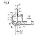
- FIG. 3 is an enlarged view of the portion of the application needle 24 and the container 21.
- the first hole 21 a opened in the bottom of the container 21, the second hole 23 a opened in the lid 23, and the application needle
- the dimensional relationship with 24 is expressed.
- the diameter of the first hole 21a is Dd
- the diameter of the second hole 23a is Du
- the diameter of the application needle 24 is D
- Dd and Du are larger than D and Dd> Du> D.
- This relational expression is valid when the application needle 24 is not a step but a straight type.
- half of the difference between the diameter Dd of the first hole 21 a and the diameter D of the application needle 24 is ⁇ d
- half of the difference between the diameter Du of the second hole 23 a and the diameter D of the application needle 24 is ⁇ d
- half of the difference between the diameter Du of the second hole 23 a and the diameter D of the application needle 24 is ⁇ d
- ⁇ d half of the difference between the diameter Du of the second hole 23 a and the diameter D of the application needle 24.
- the application needle 24 is Since it does not contact the inner surface of the first hole 21a, deformation due to wear of the first hole 21a can be suppressed. Therefore, since the amount of the ink 22 adhering to the tip 24a of the application needle 24 does not change, stable application is possible.
- the linear motion guide member 26 has a rolling guide configuration in which a rolling element (ball or the like) is interposed between the rail portion 26a and the slide portion 26b, and the rail portion 26a and the slide portion 26b are freely movable with extremely light force. It is a linear guide that can move linearly. In order to improve application accuracy, a light preload may be applied.
- Stoppers 27 and 28 are provided on the upper and lower ends of the linear motion guide member 26, respectively, to prevent the slide portion 26b from slipping out of the rail portion 26a. If the linear motion guide member 26 has a stopper function, the stoppers 27 and 28 may be omitted.
- the support base 29 is provided with an air cylinder 30 with the output shaft 30a facing upward.
- a drive plate 31 having a pin 31a fixed to the tip is fixed horizontally at the tip of the output shaft 30a of the air cylinder 30, and moves up and down integrally with the output shaft 30a.
- the pin 31a is in contact with the lower side of the notch 25a provided in the application needle fixing plate 25, and the application needle fixing plate 25 is moved by the vertical movement of the output shaft 30a of the air cylinder 30. Has the ability to move up and down.
- the container 21 is made of, for example, a resin such as polypropylene resin, fluororesin, or polyacetal resin, and a protruding portion 21b is provided on the side of the container 21.
- a magnetic pin 32 is fixed to the protrusion 21b so as to protrude upward from the protrusion 21b.
- the container 21 may be formed by injection molding. In this case, the pin 32 can be integrally formed at the time of injection molding.
- a magnet 33 is fixed to the lower end surface of the support base 29 that fixes the linear motion guide member 26.
- the container 21 is supported by being suspended from the support base 29 at one point, and the second opened in the lid 23.
- the gap ⁇ u is small, so that the container 21 is held at a predetermined position.
- the posture of the container 21 is restricted to some extent by the application needle 24 and the second hole 23a, and the posture of the container 21 is determined. Hold posture.
- the container 21 Since the first hole 21a opened at the bottom of the container 21 and the application needle 24 are not in contact with each other, the generation of dust can be prevented and the intrusion of dust into the ink 22 can be suppressed. Further, the container 21 is only supported on one surface by the suction force of the magnet 33 and the pin 32 fixed to the container 21. Even if the application needle 24 and the second hole 23 a come into contact with each other, the container 21 is fixed. Has a self-aligning property and therefore has little influence on the application needle 24.
- the surface where the pin 32 and the magnet 33 contact is almost flat, and they have a diameter of about 3 mm.
- the contact surface between the pin 32 and the magnet 33 is set so that a reference line connecting the center of the first hole 21a and the center of the second hole 23a substantially coincides with the center line of the application needle 24.
- FIGS. 4A to 4D are diagrams showing a process of applying the ink 22 to the target area 35a on the surface of the substrate 35 using the ink applying apparatus 1 shown in FIGS.
- the application mechanism unit 5 includes a sub-Z stage 34 that lowers and raises the application unit 20 in the Z-axis direction (vertical direction, the length direction of the application needle 24).
- the sub-Z stage 34 has a drive shaft 34 a that expands and contracts in the Z-axis direction, and the distal end portion of the drive shaft 34 a is fixed to the upper end portion of the support base 29.
- the sub-Z stage 34 has coordinates in the Z-axis direction, and has a function of moving the drive shaft 34a from any first coordinate to any second coordinate at a desired speed.
- the coating unit 20 and the substrate 35 are relatively moved using the XY stage 10 and the Z stage 12, and the tip of the coating needle 24 is disposed above the target area 35a of the substrate 35. .
- the output shaft 30a of the air cylinder 30 is moved downward (in the direction in which the output shaft 30a is pulled in), and the drive plate 31 that moves integrally with the output shaft 30a is moved.
- the pin 31 a fixed to the tip of the drive plate 31 is in contact with a notch 25 a provided on the application needle fixing plate 25 from below, and the application needle fixing plate 25 moves along the linear motion guide member 26 as the drive plate 31 descends.
- Move down Accordingly, the application needle 24 also moves downward, and the tip end portion 24a of the application needle 24 protrudes from the first hole 21a opened at the bottom of the container 21.
- the ink 22 is attached to the tip end portion 24a of the application needle 24, and the application needle 24 can be applied.
- the tip of the application needle 24 is disposed immediately above the target area 35a, and the distance between the tip of the application needle 24 and the surface of the target area 35a is set to a predetermined distance. That is, the tip of the application needle 24 is arranged at a predetermined position above the target area 35a.
- the entire coating unit 20 is lowered at a predetermined speed using the sub Z stage 34, and the tip of the coating needle 24 to which the ink 22 has adhered contacts the target area 35 a of the substrate 35.
- the ink 22 of the application needle tip 24a is applied to the target area 35a, and the ink layer 22a is formed.
- the load applied to the substrate 35 at the time of application is a combined weight of the slide portion 26b, the application needle fixing plate 25, and the application needle 24, for example, a light load of about 10 g.
- the output shaft 30a of the air cylinder 30 is moved upward (in the direction in which the output shaft 30a protrudes).
- the tip 24a of the application needle 24 is returned to the state immersed in the ink 22 of the container 21 and the drive shaft 34a of the sub Z stage 34 is moved upward to move the entire application unit 20 upward.
- the coating operation is completed.
- the lowering of the coating unit 20 is performed by the sub Z stage 34, but it may be performed by the Z stage 12 on which the observation optical system 2 is mounted instead.
- the ink layer 22a is applied simply by repeating the coating process shown in FIGS. 4 (A) to (D). Each time an impact is applied from the tip of the application needle 24 to the target area 35a (for example, a MEMS mechanism) via the ink layer 22a, the target area 35a may be damaged by the impact.
- the target area 35a for example, a MEMS mechanism
- FIG. 4B the tip 24a of the application needle 24 protrudes from the first hole 21a opened at the bottom of the container 21, the ink 22 adheres to the tip 24a, and the tip of the application needle 24 is the target region 35a.
- positioned in the predetermined position above the surface of was shown.
- FIG. 5A shows the tip 24a of the application needle 24 to which the ink 22 in FIG. 4B is attached.
- the coordinate in the Z-axis direction of the sub-Z stage 34 is calibrated to zero.
- the positive direction of the coordinates of the sub-Z stage 34 is set to the direction in which the application needle 24 is lowered.
- the distance d0 between the tip of the application needle 24 and the surface of the target area 35a in this state is a known value measured in advance and stored in the host computer 8.
- the distance between the tip of the application needle 24 and the surface of the substrate 35 is adjusted using the observation optical system 2 and the like, and the Z-axis direction of the sub Z stage 34 when the tip of the application needle 24 and the surface of the substrate 35 are substantially in contact with each other.
- the above-mentioned distance d0 is obtained from the coordinates and stored in the host computer 8. Further, since the length of the application needle 24 and the thickness of the substrate 35 vary, the distance d0 is corrected as appropriate.
- the sub-Z stage 34 is controlled, the tip of the application needle 24 to which the ink 22 is attached is lowered by the first distance d1, and waiting for a fixed time. To do.
- an ink layer 22a is formed between the tip of the application needle 24 and the surface of the target region 35a.
- d1 d0 ⁇ 1.
- ⁇ 1 is a known value obtained in advance by experiments, and is stored in the host computer 8.
- the tip of the application needle 24 does not directly collide with the target region 35a, so that the impact applied from the tip of the application needle 24 to the target region 35a via the ink layer 22a can be minimized.
- the sub-Z stage 34 is controlled so that the tip of the coating needle 24 to which the ink 22 is attached is a second distance smaller than the first distance d1. Lower by d2 and wait for a certain time.
- the lowering amount d2 of the application needle 24 is made smaller by the film thickness ⁇ 2 of the second ink layer 22a than the lowering amount d1 in the first application step.
- the impact applied to the target area 35a through the ink layer 22a from the tip of the ink can be minimized.
- the sub-Z stage 34 is controlled, and the tip of the application needle 24 to which the ink 22 has adhered is moved to a third distance smaller than the second distance d2. Lower by d3 and wait for a certain time.
- ⁇ 3 is a known value obtained in advance by experiments, and is stored in the host computer 8.
- the lowering amount d3 of the application needle 24 is made smaller by the film thickness ⁇ 3 of the third ink layer 22a than the lowering amount d2 in the second application step.
- the impact applied to the target area 35a through the ink layer 22a from the tip of the ink can be minimized.
- the amount d of descent of the application needle 24 is reduced as the number of applied application steps increases, so that the target region is passed from the tip of the application needle 24 through the ink layer 22a during ink application.
- the impact applied to 35a can be relieved. Therefore, the ink 22 having a high viscosity can be applied thickly without damaging the target area 35a (for example, the mechanical part of the MEMS) of the substrate 35.
- 1 pattern correction device 1 observation optical system, 3 monitor, 4 cutting laser section, 5 coating mechanism section, 6 substrate heating section, 7 image processing section, 8 host computer, 9 control computer, 10 XY stage, 11 chuck section , 12 Z stage, 20 coating unit, 21 container, 21a first hole, 22 ink, 23 lid, 23a second hole, 24 coating needle, 24a tip, 25 coating needle fixing plate, 25a notch, 26 Linear motion guide member, 26a rail part, 26b slide part, 27, 28 stopper, 29 support base, 30 air cylinder, 30a output shaft, 31 drive plate, 31a, 32 pin, 33 magnet, 35 substrate, 35a target area.
Landscapes
- Coating Apparatus (AREA)
- Application Of Or Painting With Fluid Materials (AREA)
Abstract
このインク塗布方法は、塗布針(24)の先端部(24a)にインク(22)を付着させ、基板(35)の対象領域(35a)の上方の予め定められた位置に塗布針(24)を配置し、塗布針(24)を下降および上昇させて対象領域(35a)にインク(22)を塗布し、インク層(22a)を形成する工程を複数回繰り返し実行し、複数のインク層(22a)を積層する方法において、実行した工程の回数が増大するに従って、予め定められた位置から対象領域(35a)に向けて塗布針(24)を下降させる距離を減少させるものである。したがって、インク塗布時に塗布針(24)の先端からインク層(22a)を介して対象領域(35a)に加えられる衝撃を緩和できる。
Description
この発明は塗布方法および塗布装置に関し、特に、対象物に液状材料を塗布する塗布方法および塗布装置に関する。
先端径が数十μmの塗布針を用いてインクのような液状材料を塗布する技術や、スポット径が数μm~数十μmのレーザ光を用いてパターンを加工する技術を、マイクロメートルオーダーの精密位置決め技術と組み合わせると、微細なパターンを作成したり、パターンの所定の位置を正確に加工することが可能となるので、これらの技術はフラットパネルディプレイの修正作業や太陽電池のスクライブ作業などに従来から利用されている(たとえば、特開2007-268354号公報(特許文献1)、特開2009-122259号公報(特許文献2)、特開2012-006077号公報(特許文献3)参照)。
特に塗布針を用いる技術は、ディスペンサが不得意とする粘度の高いインクでも塗布できるので、最近では、フラットパネルディプレイのパターンと比較して厚い10μm以上の厚膜の形成にも利用されている。この技術は、たとえば、MEMS(Micro Electro Mechanical Systems)やセンサなどの半導体デバイスの電子回路パターンやプリント基板配線の形成に用いられる。また、将来的に有望な製造技術であるプリンテッドエレクトロニクス技術で作製されるパターンも厚膜に分類される。したがって、塗布針を用いて液状材料を塗布する技術は、今後の用途拡大が期待される加工技術である。
ところで、たとえばMEMSに設けられた機構部の表面にインクの厚膜を形成する方法として、塗布針を用いて粘度の高いインクを繰り返し塗布し、複数のインク層を積層する方法が考えられる。しかし、この塗布方法では、インクを塗布する毎に塗布針の先端からMEMSの機構部に衝撃が印加され、MEMSの機構部が破損する恐れがある。
それゆえに、この発明の主たる目的は、対象物を破損させることなく粘度の高い液状材料を厚く塗布することが可能な塗布方法および塗布装置を提供することである。
この発明に係る塗布方法は、塗布針の先端部に液状材料を付着させ、対象物の上方の予め定められた位置に塗布針を配置し、塗布針を下降および上昇させて対象物に液状材料を塗布し、液状材料からなる液状材料層を形成する工程を複数回実行し、複数の液状材料層を積層する塗布方法において、実行した工程の回数が増大するに従って、予め定められた位置から対象物に向けて塗布針を下降させる距離を減少させるものである。
好ましくは、今回の工程において塗布針を下降させる距離は、前回の工程において塗布針を下降させた距離よりも前回の工程で形成された液状材料層の厚さ分だけ小さい。
好ましくは、その底に孔が開口され、液状材料が注入された容器と、その先端部が孔と略同じ径を有する塗布針とを備え、塗布針を下降させ、塗布針の先端部を孔から突出させて先端部に液状材料を付着させるとともに塗布針を予め定められた位置に配置する。
また、この発明に係る塗布装置は、塗布針の先端部に液状材料を付着させる塗布ユニットと、塗布ユニットと対象物を相対移動させて対象物の上方の予め定められた位置に塗布針の先端を配置する位置決め装置と、塗布針を下降および上昇させる第1の駆動装置と、塗布ユニットおよび第1の駆動装置を制御して対象物に液状材料を塗布し、液状材料からなる液状材料層を形成する工程を複数回実行し、複数の液状材料層を積層する制御装置とを備えたものである。この制御装置は、第1の駆動装置を制御し、実行した工程の回数が増大するに従って、予め定められた位置から対象物に向けて塗布針を下降させる距離を減少させる。
好ましくは、制御装置は、今回の工程において塗布針を下降させる距離を、前回の工程において塗布針を下降させた距離よりも前回の工程で形成された液状材料層の厚さ分だけ減少させる。
好ましくは、塗布ユニットは、その底に孔が開口され、液状材料が注入された容器と、その先端部が孔と略同じ径を有する塗布針と、塗布針を下降および上昇させる第2の駆動装置とを含み、制御装置は、第2の駆動装置を制御して塗布針を下降させ、塗布針の先端部を孔から突出させて先端部に液状材料を付着させる。
この発明に係る塗布方法および塗布装置では、実行した塗布工程の回数が増大するに従って塗布針の下降距離を減少させるので、塗布針の先端から液状材料層を介して対象物に加えられる衝撃を緩和することができる。したがって、対象物を破損させることなく粘度の高い液状材料を厚く塗布することができる。
図1は、この発明の一実施の形態によるインク塗布方法において使用されるインク塗布装置1の全体構成を示す図である。図1において、インク塗布装置1は、基板の表面を観察する観察光学系2と、観察された画像を映し出すモニタ3と、観察光学系2を介して基板にレーザ光を照射し不要部をカットするカット用レーザ部4と、インクを塗布針の先端部に付着させて基板の対象領域に塗布する塗布機構部5と、対象領域に塗布されたインクを加熱する基板加熱部6と、対象領域を認識する画像処理部7と、装置全体を制御するホストコンピュータ8と、装置機構部の動作を制御する制御用コンピュータ9とを備える。さらに、その他に対象領域を有する基板をXY方向(水平方向)に移動させるXYステージ10と、XYステージ10上で基板を保持するチャック部11と、観察光学系2や塗布機構部5をZ方向(垂直方向)に移動させるZステージ12などが設けられている。
XYステージ10は、塗布機構部5によってインクを対象領域に塗布する際や、観察光学系2によって基板の表面を観察する際などに、基板を適切な位置に相対移動させるために用いられる。図1に示したXYステージ10は、2つの一軸ステージを直角方向に重ねた構成を有している。ただし、このXYステージ10は、観察光学系2や塗布機構部5に対して基板を相対的に移動させることができるものであればよく、図1に示すXYステージ10の構成に限定されるものではない。基板サイズが大きい場合には、X軸方向とY軸方向にそれぞれ独立して移動可能なガントリ型のXYステージを用いてもよい。
図2(A)は、図1に示した塗布機構部5に含まれる塗布ユニット20の構成を示す断面図である。図2(A)において、塗布ユニット20は、その底に第1の孔21aが開口され、インク22が注入された容器21と、第2の孔23aが開口され、容器21を密封する蓋23と、第1および第2の孔21a,23aと略同じ径を有する塗布針24とを含む。塗布針24の先端部は、第2の孔23aを貫通してインク22に浸漬される。
図3は、塗布針24と容器21の部分を拡大した図であり、容器21の底に開口された第1の孔21aと、その蓋23に開口された第2の孔23aと、塗布針24との寸法関係を表したものである。第1の孔21aの径をDdとし、第2の孔23aの径をDuとし、塗布針24の径をDとすると、DdとDuはDよりも大きく、Dd>Du>Dの関係にある。なお、この関係式は、塗布針24が段付ではなく、ストレートのタイプの場合に成り立つ。
また、第1の孔21aの径Ddと塗布針24の径Dとの差の半分(片側隙間)をΔdとし、第2の孔23aの径Duと塗布針24の径Dとの差の半分(片側隙間)をΔuとすると、Δd>Δuの関係にあり、蓋23に開口された第2の孔23aと塗布針24との隙間よりも、容器21の底に開口された第1の孔21aと塗布針24との隙間の方が大きく設定されている。このため、第2の孔23aと塗布針24で容器21の姿勢を保つことができ、さらに、塗布針24が第2の孔23aの内面に接触した状態にあっても、塗布針24が第1の孔21aの内面に接触しないため、第1の孔21aの磨耗による変形を抑制できる。したがって、塗布針24の先端部24aに付着するインク22の液量が変化しないので安定した塗布が可能となる。
図2に戻って、塗布針24の基端部は塗布針固定板25に固定支持される。塗布針固定板25は直動案内部材26のスライド部26bに固定され、直動案内部材26のレール部26aは支持台29に固定される。直動案内部材26は、レール部26aとスライド部26bの間に転動体(ボールなど)を介在させた転がり案内の構成を有し、レール部26aとスライド部26bとは極軽い力で自在に直線運動することが可能なリニアガイドとなっている。塗布精度を向上するために、軽い予圧を与える場合もある。
直動案内部材26の上下端にはそれぞれストッパ27,28が設けられ、スライド部26bがレール部26aから抜け出ることを防止する。なお、直動案内部材26にストッパ機能が内蔵されていれば、ストッパ27,28は無くてもよい。
支持台29には、出力軸30aを上方に向けてエアシリンダ30が設けられる。エアシリンダ30の出力軸30aの先端には、先端にピン31aを固着した駆動板31が水平に固定されており、出力軸30aと一体となって上下動する。ピン31aは、図2(B)に示すように、塗布針固定板25に設けた切り欠き部25aの下方から接して、エアシリンダ30の出力軸30aの上下動により、塗布針固定板25を上下に移動させる機能を持つ。
容器21は、たとえば、ポリプロピレン樹脂、フッ素樹脂、ポリアセタール樹脂等の樹脂からなり、容器21の側部には突起部21bが設けられている。この突起部21bには、磁性体のピン32が突起部21bから上方に突出するように固着される。容器21は射出成形により作成してもよく、この場合、ピン32は射出成形時に一体成形することも可能である。
また、直動案内部材26を固定する支持台29の下端面には磁石33が固着される。容器21に固着されたピン32の上端面を磁石33の下端面に吸着させることで、容器21を支持台29に1点で吊り下げた状態で支持するとともに、蓋23に開口された第2の孔23aに塗布針24を貫通させると、その隙間Δuは小さいため、容器21は所定位置に保持される。また、容器21の底に開口した第1の孔21aと塗布針24との隙間ΔdをΔuよりも十分大きく設定することで、塗布針24は、第1の孔21aに接触することなく上下動することが可能となる。たとえば、Δd=200μm、Δu=100μmに設定する。
塗布針24が容器21の蓋23に開口した第2の孔23aに挿入されれば、容器21の姿勢は塗布針24と第2の孔23aによりある程度拘束され、容器21の姿勢が決まり、その姿勢を保持する。
容器21の底に開口した第1の孔21aと塗布針24とが接触しないため、ダストの発生を防止することができ、インク22中へのダストの侵入を抑制することができる。また、容器21は磁石33と容器21に固着したピン32の吸引力で1面支持されているだけであり、塗布針24と第2の孔23aとが接触しても、容器21の固定方法には調心性があるため、塗布針24に与える影響は少ない。ピン32と磁石33とが接する面はほぼ平らで、それらは3mm前後の直径である。なお、第1の孔21aの中心と第2の孔23aとの中心を結ぶ基準線が、塗布針24の中心線とほぼ一致するように、ピン32と磁石33の接触面が設定される。
図4(A)~(D)は、図1~図3で示したインク塗布装置1を使用して基板35の表面の対象領域35aにインク22を塗布する工程を示す図である。塗布機構部5は、塗布ユニット20をZ軸方向(垂直方向、塗布針24の長さ方向)に下降および上昇させる副Zステージ34を含む。副Zステージ34は、Z軸方向に伸縮する駆動軸34aを有し、駆動軸34aの先端部が支持台29の上端部に固定されている。副Zステージ34は、Z軸方向の座標を有し、駆動軸34aを任意の第1座標から任意の第2座標まで所望の速度で移動させる機能を有する。まず、図4(A)に示すように、XYステージ10およびZステージ12を用いて塗布ユニット20と基板35を相対移動させ、基板35の対象領域35aの上方に塗布針24の先端を配置する。
次に図4(B)に示すように、エアシリンダ30の出力軸30aを下方(図では、出力軸30aを引き込む方向)に移動させ、出力軸30aと一体となって移動する駆動板31を下方に移動させる。駆動板31の先端に固着したピン31aは、塗布針固定板25に設けた切り欠き部25aに下方から接しており、駆動板31の下降により塗布針固定板25は直動案内部材26に沿って下方に移動する。それに合わせて塗布針24も下方に移動し、容器21の底に開口された第1の孔21aから塗布針24の先端部24aが突出する。この状態で、塗布針24の先端部24aにはインク22が付着しており、塗布できる状態となる。このとき、塗布針24の先端は対象領域35aの真上に配置され、塗布針24の先端と対象領域35aの表面との間隔は所定の距離に設定されている。つまり、対象領域35aの上方の予め定められた位置に塗布針24の先端が配置される。
その後、図4(C)に示すように、副Zステージ34を用いて塗布ユニット20全体を所定の速度で下降させ、インク22が付着した塗布針24の先端を基板35の対象領域35aに接触させる。これにより、塗布針先端部24aのインク22が対象領域35aに塗布され、インク層22aが形成される。
なお、塗布針24の先端が対象領域35aに接触した後に継続して塗布ユニット20を下降させてもスライド部26bがレール部26aに沿って上方に退避するので、塗布針24の先端には過大な負荷が加わらない。そのため、塗布時に基板35に加えられる荷重は、スライド部26bと、塗布針固定板25と、塗布針24の合成重量となり、たとえば、約10g前後と軽荷重である。
塗布針24の先端を一定時間、対象領域35aに接触させた後、図4(D)に示すように、エアシリンダ30の出力軸30aを上方(図では、出力軸30aを突出させる方向)に移動させ、塗布針24の先端部24aを容器21のインク22中に浸漬した状態に戻すとともに、副Zステージ34の駆動軸34aを上方に移動させて塗布ユニット20全体を上方に移動させ、1回の塗布動作が終了する。
なお、ここでは塗布ユニット20の下降を副Zステージ34によって行なっているが、その代わりに観察光学系2を搭載したZステージ12によって行なってもよい。
このような塗布装置1を使用し、複数のインク層22aを積層して厚膜を作成する場合、単に図4(A)~(D)で示した塗布工程を繰り返すと、インク層22aを塗布する毎に塗布針24の先端からインク層22aを介して対象領域35a(たとえばMEMSの機構部)に衝撃が印加され、その衝撃によって対象領域35aが破損する恐れがある。
そこで本実施の形態によるインク塗布方法では、図4(B)で示した予め定められた位置から対象領域35aに向けて塗布針24を下降させる距離(下降量)dを、実行した塗布工程の回数に応じて減少させ、塗布針24の先端からインク層22aを介して対象領域35aに印加される衝撃を緩和する。
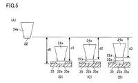
図4(B)では、容器21の底に開口された第1の孔21aから塗布針24の先端部24aが突出し、先端部24aにインク22が付着し、塗布針24の先端が対象領域35aの表面の上方の予め定められた位置に配置された状態を示した。図5(A)は、図4(B)のうちのインク22が付着した塗布針24の先端部24aを示している。このとき、副Zステージ34のZ軸方向の座標が0に較正される。副Zステージ34の座標の正方向は、塗布針24を下降させる方向に設定されている。
また、この状態における塗布針24の先端と対象領域35aの表面との間の距離d0は予め測定された既知の値であり、ホストコンピュータ8に記憶されている。観察光学系2などを用いて塗布針24の先端と基板35の表面との距離を調整し、塗布針24の先端と基板35の表面とが略接触するときにおける副Zステージ34のZ軸方向の座標から上記の距離d0を求め、ホストコンピュータ8に記憶させる。また、塗布針24の長さや基板35の厚さにはばらつきがあるので、距離d0は適宜補正される。
第1回目の塗布工程では、図4(C)で示したように、副Zステージ34を制御し、インク22が付着した塗布針24の先端を第1の距離d1だけ下降させ、一定時間待機する。この場合は、図5(B)に示すように、塗布針24の先端と対象領域35aの表面との間にインク層22aが形成される。第1層目のインク層22aの膜厚をα1とすると、d1=d0-α1である。α1は、予め実験によって求められた既知の値であり、ホストコンピュータ8に記憶されている。この塗布工程では、塗布針24の先端が対象領域35aに直接衝突しないので、塗布針24の先端からインク層22aを介して対象領域35aに印加される衝撃を最小限に抑制することができる。
第2回目の塗布工程では、図4(C)で示したように、副Zステージ34を制御し、インク22が付着した塗布針24の先端を第1の距離d1よりも小さな第2の距離d2だけ下降させ、一定時間待機する。この場合は、図5(C)に示すように、塗布針24の先端と対象領域35aの表面との間に2つのインク層22aが積層される。第2層目のインク層22aの膜厚をα2とすると、d2=d0-α1-α2=d1-α2である。α2は、予め実験によって求められた既知の値であり、ホストコンピュータ8に記憶されている。この第2回目の塗布工程では、塗布針24の下降量d2を第1回目の塗布工程における下降量d1よりも第2層目のインク層22aの膜厚α2分だけ小さくするので、塗布針24の先端からインク層22aを介して対象領域35aに印加される衝撃を最小限に抑制することができる。
第3回目の塗布工程では、図4(C)で示したように、副Zステージ34を制御し、インク22が付着した塗布針24の先端を第2の距離d2よりも小さな第3の距離d3だけ下降させ、一定時間待機する。この場合は、図5(D)に示すように、塗布針24の先端と対象領域35aの表面との間に3つのインク層22aが積層される。第3層目のインク層22aの膜厚をα3とすると、d3=d0-α1-α2-α3=d2-α3である。α3は、予め実験によって求められた既知の値であり、ホストコンピュータ8に記憶されている。この第3回目の塗布工程では、塗布針24の下降量d3を第2回目の塗布工程における下降量d2よりも第3層目のインク層22aの膜厚α3分だけ小さくするので、塗布針24の先端からインク層22aを介して対象領域35aに印加される衝撃を最小限に抑制することができる。
以上のように、本実施の形態では、実行した塗布工程の回数が増大するに従って塗布針24の下降量dを減少させるので、インク塗布時に塗布針24の先端からインク層22aを介して対象領域35aに印加される衝撃を緩和することができる。したがって、基板35の対象領域35a(たとえばMEMSの機構部)を破損させることなく粘度の高いインク22を厚く塗布することができる。
今回開示された実施の形態はすべての点で例示であって制限的なものではないと考えられるべきである。本発明の範囲は上記した説明ではなくて請求の範囲によって示され、請求の範囲と均等の意味および範囲内でのすべての変更が含まれることが意図される。
1 パターン修正装置、2 観察光学系、3 モニタ、4 カット用レーザ部、5 塗布機構部、6 基板加熱部、7 画像処理部、8 ホストコンピュータ、9 制御用コンピュータ、10 XYステージ、11 チャック部、12 Zステージ、20 塗布ユニット、21 容器、21a 第1の孔、22 インク、23 蓋、23a 第2の孔、24 塗布針、24a 先端部、25 塗布針固定板、25a 切り欠き部、26 直動案内部材、26a レール部、26b スライド部、27,28 ストッパ、29 支持台、30 エアシリンダ、30a 出力軸、31 駆動板、31a,32 ピン、33 磁石、35 基板、35a 対象領域。
Claims (6)
- 塗布針の先端部に液状材料を付着させ、対象物の上方の予め定められた位置に前記塗布針を配置し、前記塗布針を下降および上昇させて前記対象物に前記液状材料を塗布し、前記液状材料からなる液状材料層を形成する工程を複数回実行し、複数の前記液状材料層を積層する塗布方法において、
実行した前記工程の回数が増大するに従って、前記予め定められた位置から前記対象物に向けて前記塗布針を下降させる距離を減少させる、塗布方法。 - 今回の前記工程において前記塗布針を下降させる距離は、前回の前記工程において前記塗布針を下降させた距離よりも前回の前記工程で形成された前記液状材料層の厚さ分だけ小さい、請求項1に記載の塗布方法。
- その底に孔が開口され、前記液状材料が注入された容器と、
その先端部が前記孔と略同じ径を有する前記塗布針とを備え、
前記塗布針を下降させ、前記塗布針の先端部を前記孔から突出させて前記先端部に前記液状材料を付着させるとともに前記塗布針を前記予め定められた位置に配置する、請求項1または請求項2に記載の塗布方法。 - 塗布針の先端部に液状材料を付着させる塗布ユニットと、
前記塗布ユニットと対象物を相対移動させて前記対象物の上方の予め定められた位置に前記塗布針の先端を配置する位置決め装置と、
前記塗布針を下降および上昇させる第1の駆動装置と、
前記塗布ユニットおよび前記第1の駆動装置を制御して前記対象物に前記液状材料を塗布し、前記液状材料からなる液状材料層を形成する工程を複数回実行し、複数の前記液状材料層を積層する制御装置とを備え、
前記制御装置は、前記第1の駆動装置を制御し、実行した前記工程の回数が増大するに従って、前記予め定められた位置から前記対象物に向けて前記塗布針を下降させる距離を減少させる、塗布装置。 - 前記制御装置は、今回の前記工程において前記塗布針を下降させる距離を、前回の前記工程において前記塗布針を下降させた距離よりも前回の前記工程で形成された前記液状材料層の厚さ分だけ減少させる、請求項4に記載の塗布装置。
- 前記塗布ユニットは、
その底に孔が開口され、前記液状材料が注入された容器と、
その先端部が前記孔と略同じ径を有する前記塗布針と、
前記塗布針を下降および上昇させる第2の駆動装置とを含み、
前記制御装置は、前記第2の駆動装置を制御して前記塗布針を下降させ、前記塗布針の先端部を前記孔から突出させて前記先端部に前記液状材料を付着させる、請求項4または請求項5に記載の塗布装置。
Priority Applications (1)
| Application Number | Priority Date | Filing Date | Title |
|---|---|---|---|
| CN201580050338.0A CN106714982B (zh) | 2014-09-22 | 2015-09-07 | 涂布方法及涂布装置 |
Applications Claiming Priority (2)
| Application Number | Priority Date | Filing Date | Title |
|---|---|---|---|
| JP2014-192530 | 2014-09-22 | ||
| JP2014192530A JP6404654B2 (ja) | 2014-09-22 | 2014-09-22 | 塗布方法および塗布装置 |
Publications (1)
| Publication Number | Publication Date |
|---|---|
| WO2016047423A1 true WO2016047423A1 (ja) | 2016-03-31 |
Family
ID=55580951
Family Applications (1)
| Application Number | Title | Priority Date | Filing Date |
|---|---|---|---|
| PCT/JP2015/075293 Ceased WO2016047423A1 (ja) | 2014-09-22 | 2015-09-07 | 塗布方法および塗布装置 |
Country Status (3)
| Country | Link |
|---|---|
| JP (1) | JP6404654B2 (ja) |
| CN (1) | CN106714982B (ja) |
| WO (1) | WO2016047423A1 (ja) |
Cited By (5)
| Publication number | Priority date | Publication date | Assignee | Title |
|---|---|---|---|---|
| WO2019054458A1 (ja) * | 2017-09-15 | 2019-03-21 | Ntn株式会社 | 液体材料塗布方法、液体材料塗布機構および液体材料塗布装置 |
| JPWO2019088224A1 (ja) * | 2017-11-02 | 2019-11-14 | 国立大学法人大阪大学 | 細胞チップおよび三次元組織チップ、およびその製造方法 |
| JP2019208476A (ja) * | 2018-06-08 | 2019-12-12 | 国立大学法人大阪大学 | 細胞チップおよび細胞組織チップの製造方法 |
| WO2019235513A1 (ja) * | 2018-06-08 | 2019-12-12 | 国立大学法人大阪大学 | 塗布ユニット、微細塗布装置、並びに細胞チップおよび細胞組織チップの製造方法 |
| JP2019209301A (ja) * | 2018-06-08 | 2019-12-12 | 国立大学法人大阪大学 | 塗布ユニットおよび微細塗布装置 |
Families Citing this family (1)
| Publication number | Priority date | Publication date | Assignee | Title |
|---|---|---|---|---|
| JP7535965B2 (ja) | 2020-03-13 | 2024-08-19 | Ntn株式会社 | 液体材料塗布ユニット、液体材料塗布装置および液体材料塗布方法 |
Citations (3)
| Publication number | Priority date | Publication date | Assignee | Title |
|---|---|---|---|---|
| JP2008192901A (ja) * | 2007-02-06 | 2008-08-21 | Ntn Corp | パターン修正装置およびそれに用いられる塗布ユニット |
| JP2010062385A (ja) * | 2008-09-04 | 2010-03-18 | Ntn Corp | フラックス塗布装置およびフラックス塗布方法 |
| JP2012101175A (ja) * | 2010-11-10 | 2012-05-31 | Ntn Corp | 塗布機構、塗布方法、および塗布装置 |
Family Cites Families (5)
| Publication number | Priority date | Publication date | Assignee | Title |
|---|---|---|---|---|
| JP3663448B2 (ja) * | 1999-12-07 | 2005-06-22 | 株式会社ヒラノテクシード | 毛管現象を用いる塗工装置 |
| JP4719050B2 (ja) * | 2006-03-30 | 2011-07-06 | Ntn株式会社 | パターン修正装置およびその塗布ユニット |
| JP4945817B2 (ja) * | 2008-08-13 | 2012-06-06 | 株式会社アプライド・マイクロシステム | 液状物吐出装置 |
| JP2010232326A (ja) * | 2009-03-26 | 2010-10-14 | Toray Eng Co Ltd | 塗布装置 |
| JP2015205226A (ja) * | 2014-04-17 | 2015-11-19 | 芝浦メカトロニクス株式会社 | 塗布装置、接着剤塗布ワーク製造方法、表示装置用部材の製造装置、表示装置用部材の製造方法 |
-
2014
- 2014-09-22 JP JP2014192530A patent/JP6404654B2/ja active Active
-
2015
- 2015-09-07 CN CN201580050338.0A patent/CN106714982B/zh active Active
- 2015-09-07 WO PCT/JP2015/075293 patent/WO2016047423A1/ja not_active Ceased
Patent Citations (3)
| Publication number | Priority date | Publication date | Assignee | Title |
|---|---|---|---|---|
| JP2008192901A (ja) * | 2007-02-06 | 2008-08-21 | Ntn Corp | パターン修正装置およびそれに用いられる塗布ユニット |
| JP2010062385A (ja) * | 2008-09-04 | 2010-03-18 | Ntn Corp | フラックス塗布装置およびフラックス塗布方法 |
| JP2012101175A (ja) * | 2010-11-10 | 2012-05-31 | Ntn Corp | 塗布機構、塗布方法、および塗布装置 |
Cited By (10)
| Publication number | Priority date | Publication date | Assignee | Title |
|---|---|---|---|---|
| WO2019054458A1 (ja) * | 2017-09-15 | 2019-03-21 | Ntn株式会社 | 液体材料塗布方法、液体材料塗布機構および液体材料塗布装置 |
| JPWO2019088224A1 (ja) * | 2017-11-02 | 2019-11-14 | 国立大学法人大阪大学 | 細胞チップおよび三次元組織チップ、およびその製造方法 |
| CN111601880A (zh) * | 2017-11-02 | 2020-08-28 | 国立大学法人大阪大学 | 细胞芯片及三维组织芯片、及其制造方法 |
| EP3705567A4 (en) * | 2017-11-02 | 2021-08-04 | Osaka University | CELL CHIP AND THREE-DIMENSIONAL TISSUE CHIP AND THE PROCESS FOR ITS MANUFACTURING |
| US12203062B2 (en) | 2017-11-02 | 2025-01-21 | Osaka University | Cell chip and three-dimensional tissue chip, and method for producing same |
| JP2019208476A (ja) * | 2018-06-08 | 2019-12-12 | 国立大学法人大阪大学 | 細胞チップおよび細胞組織チップの製造方法 |
| WO2019235513A1 (ja) * | 2018-06-08 | 2019-12-12 | 国立大学法人大阪大学 | 塗布ユニット、微細塗布装置、並びに細胞チップおよび細胞組織チップの製造方法 |
| JP2019209301A (ja) * | 2018-06-08 | 2019-12-12 | 国立大学法人大阪大学 | 塗布ユニットおよび微細塗布装置 |
| JP7024970B2 (ja) | 2018-06-08 | 2022-02-24 | 国立大学法人大阪大学 | 塗布ユニットおよび微細塗布装置 |
| JP7142841B2 (ja) | 2018-06-08 | 2022-09-28 | 国立大学法人大阪大学 | 細胞チップおよび細胞組織チップの製造方法 |
Also Published As
| Publication number | Publication date |
|---|---|
| JP6404654B2 (ja) | 2018-10-10 |
| JP2016059909A (ja) | 2016-04-25 |
| CN106714982A (zh) | 2017-05-24 |
| CN106714982B (zh) | 2021-05-25 |
Similar Documents
| Publication | Publication Date | Title |
|---|---|---|
| JP6404654B2 (ja) | 塗布方法および塗布装置 | |
| KR102835738B1 (ko) | 미세-조정으로 반도체 디바이스의 이송 속도를 증가시키기 위한 방법 및 장치 | |
| US8628648B2 (en) | Apparatus and method for manipulating micro component | |
| US20170069844A1 (en) | Aligner structure and alignment method | |
| US20230211558A1 (en) | Robotic systems for additive manufacturing | |
| KR102353875B1 (ko) | 잉크제트 좌표계에 대한 기판 좌표계의 정밀 정렬 | |
| CN114512584B (zh) | 一种Mini/micro芯片快速转移封装系统 | |
| US9952505B2 (en) | Imprint device and pattern forming method | |
| JPWO2020013237A1 (ja) | 電子部品の製造装置 | |
| US9567663B2 (en) | Manufacturing apparatus and method of mask assembly | |
| JP6460694B2 (ja) | 塗布方法および塗布装置 | |
| WO2016199695A1 (ja) | 液体塗布ユニットおよび液体塗布装置 | |
| KR102731980B1 (ko) | 리소그래피 장치 및 물품의 제조 방법 | |
| KR101830009B1 (ko) | 전사 장치 및 전사 방법 | |
| Arutinov et al. | Capillary gripping and self-alignment: A route toward autonomous heterogeneous assembly | |
| Sariola et al. | Experimental study on droplet based hybrid microhandling using high speed camera | |
| JP6745683B2 (ja) | 液体塗布ユニット、液体塗布装置および液体塗布方法 | |
| WO2015122449A1 (ja) | 部品実装装置、及び検知装置 | |
| JP6587945B2 (ja) | 塗布機構、塗布装置、被塗布対象物の製造方法、および基板の製造方法 | |
| JP6599655B2 (ja) | 液状材料塗布装置 | |
| US20250201759A1 (en) | Method of bonding chips and a system for performing the method | |
| US20260123344A1 (en) | Semiconductor Substrate Bonder for Enhanced Precision with Zonal Electrostatic Chuck | |
| JP6830330B2 (ja) | 液体塗布ユニット、液体塗布装置、および液体塗布方法 | |
| JP2010224338A (ja) | 封止構造体の製造装置及び封止構造体の製造方法 | |
| US9918420B2 (en) | Apparatus and method of batch assembly |
Legal Events
| Date | Code | Title | Description |
|---|---|---|---|
| 121 | Ep: the epo has been informed by wipo that ep was designated in this application |
Ref document number: 15843661 Country of ref document: EP Kind code of ref document: A1 |
|
| NENP | Non-entry into the national phase |
Ref country code: DE |
|
| 122 | Ep: pct application non-entry in european phase |
Ref document number: 15843661 Country of ref document: EP Kind code of ref document: A1 |