WO2016047271A1 - 車両制御装置 - Google Patents
車両制御装置 Download PDFInfo
- Publication number
- WO2016047271A1 WO2016047271A1 PCT/JP2015/071769 JP2015071769W WO2016047271A1 WO 2016047271 A1 WO2016047271 A1 WO 2016047271A1 JP 2015071769 W JP2015071769 W JP 2015071769W WO 2016047271 A1 WO2016047271 A1 WO 2016047271A1
- Authority
- WO
- WIPO (PCT)
- Prior art keywords
- rotor
- electrical machine
- torque
- rotating electrical
- rotating
- Prior art date
- Legal status (The legal status is an assumption and is not a legal conclusion. Google has not performed a legal analysis and makes no representation as to the accuracy of the status listed.)
- Ceased
Links
Images



Classifications
-
- B—PERFORMING OPERATIONS; TRANSPORTING
- B60—VEHICLES IN GENERAL
- B60K—ARRANGEMENT OR MOUNTING OF PROPULSION UNITS OR OF TRANSMISSIONS IN VEHICLES; ARRANGEMENT OR MOUNTING OF PLURAL DIVERSE PRIME-MOVERS IN VEHICLES; AUXILIARY DRIVES FOR VEHICLES; INSTRUMENTATION OR DASHBOARDS FOR VEHICLES; ARRANGEMENTS IN CONNECTION WITH COOLING, AIR INTAKE, GAS EXHAUST OR FUEL SUPPLY OF PROPULSION UNITS IN VEHICLES
- B60K6/00—Arrangement or mounting of plural diverse prime-movers for mutual or common propulsion, e.g. hybrid propulsion systems comprising electric motors and internal combustion engines
- B60K6/20—Arrangement or mounting of plural diverse prime-movers for mutual or common propulsion, e.g. hybrid propulsion systems comprising electric motors and internal combustion engines the prime-movers consisting of electric motors and internal combustion engines, e.g. HEVs
- B60K6/22—Arrangement or mounting of plural diverse prime-movers for mutual or common propulsion, e.g. hybrid propulsion systems comprising electric motors and internal combustion engines the prime-movers consisting of electric motors and internal combustion engines, e.g. HEVs characterised by apparatus, components or means specially adapted for HEVs
- B60K6/26—Arrangement or mounting of plural diverse prime-movers for mutual or common propulsion, e.g. hybrid propulsion systems comprising electric motors and internal combustion engines the prime-movers consisting of electric motors and internal combustion engines, e.g. HEVs characterised by apparatus, components or means specially adapted for HEVs characterised by the motors or the generators
-
- B—PERFORMING OPERATIONS; TRANSPORTING
- B60—VEHICLES IN GENERAL
- B60K—ARRANGEMENT OR MOUNTING OF PROPULSION UNITS OR OF TRANSMISSIONS IN VEHICLES; ARRANGEMENT OR MOUNTING OF PLURAL DIVERSE PRIME-MOVERS IN VEHICLES; AUXILIARY DRIVES FOR VEHICLES; INSTRUMENTATION OR DASHBOARDS FOR VEHICLES; ARRANGEMENTS IN CONNECTION WITH COOLING, AIR INTAKE, GAS EXHAUST OR FUEL SUPPLY OF PROPULSION UNITS IN VEHICLES
- B60K6/00—Arrangement or mounting of plural diverse prime-movers for mutual or common propulsion, e.g. hybrid propulsion systems comprising electric motors and internal combustion engines
- B60K6/20—Arrangement or mounting of plural diverse prime-movers for mutual or common propulsion, e.g. hybrid propulsion systems comprising electric motors and internal combustion engines the prime-movers consisting of electric motors and internal combustion engines, e.g. HEVs
- B60K6/42—Arrangement or mounting of plural diverse prime-movers for mutual or common propulsion, e.g. hybrid propulsion systems comprising electric motors and internal combustion engines the prime-movers consisting of electric motors and internal combustion engines, e.g. HEVs characterised by the architecture of the hybrid electric vehicle
- B60K6/44—Series-parallel type
- B60K6/448—Electrical distribution type
-
- B—PERFORMING OPERATIONS; TRANSPORTING
- B60—VEHICLES IN GENERAL
- B60L—PROPULSION OF ELECTRICALLY-PROPELLED VEHICLES; SUPPLYING ELECTRIC POWER FOR AUXILIARY EQUIPMENT OF ELECTRICALLY-PROPELLED VEHICLES; ELECTRODYNAMIC BRAKE SYSTEMS FOR VEHICLES IN GENERAL; MAGNETIC SUSPENSION OR LEVITATION FOR VEHICLES; MONITORING OPERATING VARIABLES OF ELECTRICALLY-PROPELLED VEHICLES; ELECTRIC SAFETY DEVICES FOR ELECTRICALLY-PROPELLED VEHICLES
- B60L15/00—Methods, circuits, or devices for controlling the traction-motor speed of electrically-propelled vehicles
- B60L15/20—Methods, circuits, or devices for controlling the traction-motor speed of electrically-propelled vehicles for control of the vehicle or its driving motor to achieve a desired performance, e.g. speed, torque, programmed variation of speed
-
- B—PERFORMING OPERATIONS; TRANSPORTING
- B60—VEHICLES IN GENERAL
- B60W—CONJOINT CONTROL OF VEHICLE SUB-UNITS OF DIFFERENT TYPE OR DIFFERENT FUNCTION; CONTROL SYSTEMS SPECIALLY ADAPTED FOR HYBRID VEHICLES; ROAD VEHICLE DRIVE CONTROL SYSTEMS FOR PURPOSES NOT RELATED TO THE CONTROL OF A PARTICULAR SUB-UNIT
- B60W10/00—Conjoint control of vehicle sub-units of different type or different function
- B60W10/04—Conjoint control of vehicle sub-units of different type or different function including control of propulsion units
- B60W10/06—Conjoint control of vehicle sub-units of different type or different function including control of propulsion units including control of combustion engines
-
- B—PERFORMING OPERATIONS; TRANSPORTING
- B60—VEHICLES IN GENERAL
- B60W—CONJOINT CONTROL OF VEHICLE SUB-UNITS OF DIFFERENT TYPE OR DIFFERENT FUNCTION; CONTROL SYSTEMS SPECIALLY ADAPTED FOR HYBRID VEHICLES; ROAD VEHICLE DRIVE CONTROL SYSTEMS FOR PURPOSES NOT RELATED TO THE CONTROL OF A PARTICULAR SUB-UNIT
- B60W10/00—Conjoint control of vehicle sub-units of different type or different function
- B60W10/04—Conjoint control of vehicle sub-units of different type or different function including control of propulsion units
- B60W10/08—Conjoint control of vehicle sub-units of different type or different function including control of propulsion units including control of electric propulsion units, e.g. motors or generators
-
- B—PERFORMING OPERATIONS; TRANSPORTING
- B60—VEHICLES IN GENERAL
- B60W—CONJOINT CONTROL OF VEHICLE SUB-UNITS OF DIFFERENT TYPE OR DIFFERENT FUNCTION; CONTROL SYSTEMS SPECIALLY ADAPTED FOR HYBRID VEHICLES; ROAD VEHICLE DRIVE CONTROL SYSTEMS FOR PURPOSES NOT RELATED TO THE CONTROL OF A PARTICULAR SUB-UNIT
- B60W20/00—Control systems specially adapted for hybrid vehicles
-
- Y—GENERAL TAGGING OF NEW TECHNOLOGICAL DEVELOPMENTS; GENERAL TAGGING OF CROSS-SECTIONAL TECHNOLOGIES SPANNING OVER SEVERAL SECTIONS OF THE IPC; TECHNICAL SUBJECTS COVERED BY FORMER USPC CROSS-REFERENCE ART COLLECTIONS [XRACs] AND DIGESTS
- Y02—TECHNOLOGIES OR APPLICATIONS FOR MITIGATION OR ADAPTATION AGAINST CLIMATE CHANGE
- Y02T—CLIMATE CHANGE MITIGATION TECHNOLOGIES RELATED TO TRANSPORTATION
- Y02T10/00—Road transport of goods or passengers
- Y02T10/60—Other road transportation technologies with climate change mitigation effect
- Y02T10/62—Hybrid vehicles
-
- Y—GENERAL TAGGING OF NEW TECHNOLOGICAL DEVELOPMENTS; GENERAL TAGGING OF CROSS-SECTIONAL TECHNOLOGIES SPANNING OVER SEVERAL SECTIONS OF THE IPC; TECHNICAL SUBJECTS COVERED BY FORMER USPC CROSS-REFERENCE ART COLLECTIONS [XRACs] AND DIGESTS
- Y02—TECHNOLOGIES OR APPLICATIONS FOR MITIGATION OR ADAPTATION AGAINST CLIMATE CHANGE
- Y02T—CLIMATE CHANGE MITIGATION TECHNOLOGIES RELATED TO TRANSPORTATION
- Y02T10/00—Road transport of goods or passengers
- Y02T10/60—Other road transportation technologies with climate change mitigation effect
- Y02T10/72—Electric energy management in electromobility
Definitions
- the present invention relates to a vehicle control device, and more particularly to a vehicle control device for a vehicle that travels using an internal combustion engine and a rotating electrical machine.
- Some hybrid vehicles that travel using an internal combustion engine and a rotating electrical machine include, for example, two rotating electrical machines and one engine (internal combustion engine) as disclosed in Patent Document 1.
- the rotor of the first rotating electrical machine is connected to the output shaft of the engine, and the rotor of the second rotating electrical machine is connected to the differential device of the vehicle wheel shaft.
- the second rotating electrical machine is not connected to the engine and the first rotating electrical machine.
- the first rotating electrical machine has a function as a generator that generates electric power by driving the engine.
- the second rotating electrical machine has a function as an electric motor that rotationally drives the wheels.
- the double rotor type rotating electrical machine is a rotor to which an output shaft of an engine is connected and an inner rotor arranged at the innermost side, and an outer arranged at the radially outer side of the inner rotor and connected to a differential device.
- a rotor and a stator that is disposed on the outer side in the radial direction of the outer rotor and is fixed to a casing or the like.
- a three-phase winding is wound around the inner rotor and the stator, and a permanent magnet is provided on the outer rotor.
- the three-phase winding is electrically connected to the inverter, can receive power supply through the inverter, and can transmit the generated power to the inverter.
- the inner rotor and the outer rotor constitute one inner rotating electric machine
- the outer rotor and the stator constitute one outer rotating electric machine.
- a double rotor type rotating electric machine for example, when acceleration in a high speed state is required for a vehicle, rotation to drive the outer rotating electric machine by the action of a rotating magnetic field generated from a three-phase winding by supplying electric power to the stator
- rotational torque for rotationally driving the inner rotating electrical machine is required.
- the two rotational torques can cooperate to give a high rotational torque to the vehicle.
- power is supplied to the inner rotor and the inner rotor is rotationally driven by the engine in order to obtain a high rotational torque.
- the present invention has been made to solve the above-described problems, and provides a vehicle control device that suppresses a reduction in efficiency of a rotating electrical machine when magnetic flux interference occurs in a double rotor type rotating electrical machine. Objective.
- a vehicle control device is provided with an internal combustion engine, a rotatable first rotor, and a second rotor that is relatively rotatable on the outer side in the rotational radial direction with respect to the first rotor.
- a rotating electrical machine including a rotor and a stator fixedly disposed on the outer side in the rotational radial direction of the second rotor, and a control unit that controls operations of the rotating electrical machine and the internal combustion engine, the first rotor and the second rotor
- One of the rotors is mechanically coupled to the internal combustion engine, and the other of the first rotor and the second rotor is mechanically coupled to the vehicle drive mechanism.
- first rotating electrical machine unit configured by a rotor and a second rotor
- second rotating electrical machine unit configured by a second rotor and a stator.
- first rotor or the second rotor is The first rotor and the first rotor can be driven to rotate relative to each other, and the first rotor and the second rotor can rotate relative to each other to generate an induced current to generate power.
- the second rotating electrical machine unit is capable of rotating the second rotor with respect to the stator by supplying a current and generating a rotating magnetic field, and the second rotor with respect to the stator.
- the control unit It is possible to generate electric power by generating an induced current by relatively rotating, and the control unit generates a rotating magnetic field or a magnetic field due to the induced current in each of the first rotating electrical machine unit and the second rotating electrical machine unit.
- the first rotating electric machine part and the first rotating electric machine part are controlled so as to suppress the decrease in the efficiency of the rotating electric machine while maintaining the sum of the torques generated by the first rotating electric machine part and the second rotating electric machine part. Controls the current flowing through the two-rotating electric machine.
- the vehicle control apparatus of the present invention it is possible to suppress a decrease in efficiency of the double rotor type rotating electrical machine when magnetic flux interference occurs.
- a vehicle control device 101 includes an engine 10 that is an internal combustion engine and a rotating electrical machine 30 that is a double rotor type motor that is operated by three-phase AC power as a power device of a hybrid vehicle.
- the rotating electrical machine 30 includes a rotatable first rotor 31, a rotatable second rotor 32, and a stator 33 that is fixedly disposed on a casing (not shown) of the rotating electrical machine 30.
- the first rotor 31 constitutes a first rotor
- the second rotor 32 constitutes a second rotor
- the stator 33 constitutes a stator.
- the first rotor 31 is disposed on the most central side among the first rotor 31, the second rotor 32, and the stator 33.
- the input shaft 40 constituting the rotating shaft of the first rotor 31 is mechanically connected to the engine output shaft 11 of the engine 10 via an electromagnetic clutch 41.
- the electromagnetic clutch 41 selectively operates so that the input shaft 40 and the engine output shaft 11 are in a connected state that enables power transmission and a disconnected state that interrupts power transmission.
- the mechanical connection means that the input shaft 40 and the engine output shaft 11 are connected to each other only through the electromagnetic clutch 41, and that in addition to the electromagnetic clutch 41, a speed increaser and a speed reducer. And a case of being connected via a speed change mechanism or the like.
- the first rotor 31 includes a cylindrical first core 31a provided to be rotatable integrally with the input shaft 40 so as to surround the outer periphery of the input shaft 40, and a first rotor 31 provided along the circumferential direction in the first core 31a.
- the first winding 31b is a three-phase winding.
- the second rotor 32 includes a second core 32a that is provided on the radially outer side of the first rotor 31 so as to surround the outer periphery of the first rotor 31 and has a cylindrical shape, and a second core 32a that faces the first core 31a.
- a first permanent magnet 32b embedded in the vicinity of the inner peripheral surface along the circumferential direction, and a second permanent magnet 32c embedded in the vicinity of the outer peripheral surface of the second core 32a opposite to the inner peripheral surface along the circumferential direction. have. That is, the first permanent magnet 32b is positioned to face the first winding 31b.
- the second core 32a is held by a bottomed cylindrical support housing 32d that is provided so as to surround the outer periphery of the input shaft 40 and the first rotor 31 and is rotatably supported by the input shaft 40 via a bearing (not shown).
- the second core 32a and the support housing 32d can be integrally rotated around the input shaft 40 and the first rotor 31 relative to them.
- the stator 33 is provided on the outer side in the radial direction of the second rotor 32 so as to surround the outer periphery of the second rotor 32 and has a cylindrical stator core 33a, and the stator core 33a has a circumferential surface in the vicinity of the inner peripheral surface facing the second core 32a. And a second winding 33b provided along the direction. The second winding 33b is located opposite to the second permanent magnet 32c and is a three-phase winding.
- the stator core 33a is fixed to a casing (not shown) of the rotating electrical machine 30.
- an inner motor 30 a that is one motor that includes the first rotor 31 and the second rotor 32 and that is positioned on the inner side is formed, and that that includes the second rotor 32 and the stator 33 and that is positioned on the outer side.
- An outer motor 30b which is one motor, is formed.
- the inner motor 30a constitutes a first rotating electrical machine part
- the outer motor 30b constitutes a second rotating electrical machine part.
- FIG. 1 cross sections of the first rotor 31, the second rotor 32, and the stator 33 are schematically shown.
- the output shaft 50 is mechanically connected to the support housing 32d of the second rotor 32 so as to rotate integrally.
- a pinion gear 61 is attached to the end of the output shaft 50 so as to rotate integrally.
- the pinion gear 61 is in gear engagement with the driven gear 62.
- the driven gear 62 is attached to a drive shaft 71 connected to a vehicle wheel (not shown) via a differential gear so as to rotate integrally. Therefore, when the 2nd rotor 32 and the support housing 32d rotate together, the drive shaft 71 is rotationally driven, and, thereby, a wheel is rotationally driven.
- the support housing 32d of the second rotor 32 is mechanically connected to the drive shaft 71 via a mechanical power transmission mechanism such as a transmission in addition to the output shaft 50, the pinion gear 61, and the driven gear 62. It may be.
- a mechanical power transmission mechanism such as a transmission in addition to the output shaft 50, the pinion gear 61, and the driven gear 62. It may be.
- the output shaft 50, the pinion gear 61, the driven gear 62, and the drive shaft 71 constitute a vehicle drive mechanism 80.
- the vehicle control apparatus 101 includes a battery 23 that can charge and discharge DC power, and a first inverter 21 and a second inverter 22 that are electrically connected to the battery 23.
- the first inverter 21 and the second inverter 22 can convert the DC power supplied from the battery 23 into three-phase AC power, and can also convert the three-phase AC power into DC power and supply it to the battery 23.
- the first inverter 21 and the second inverter 22 are controlled by a control unit (hereinafter referred to as ECU) 90 described later.
- the ECU 90 constitutes a control unit.
- the first inverter 21 is electrically connected to a slip ring mechanism 24 attached around the input shaft 40.
- the three-phase AC power output from the first inverter 21 is transmitted to a conductor (not shown) provided along the input shaft 40 via the slip ring mechanism 24, and passes through this conductor to the first rotor 31. It is supplied to the first winding 31b.
- this induced current is supplied to the first inverter 21 via the conductor and the slip ring mechanism 24, and is converted into a direct current by the first inverter 21. And then supplied to the battery 23.
- the second inverter 22 is electrically connected to the second winding 33b of the stator 33. Thereby, the three-phase AC power output from the second inverter 22 is supplied to the second winding 33b.
- this induced current is supplied to the second inverter 22, converted into a direct current by the second inverter 22, and then supplied to the battery 23.
- the ECU 90 controls the power supply to the first winding 31 b of the first rotor 31 and the second winding 33 b of the stator 33 by controlling the first inverter 21 and the second inverter 22.
- the ECU 90 is electrically connected to an engine torque sensor 10a that detects the torque of the engine 10 and an engine speed sensor 10b that detects the rotational speed of the engine 10, and the detected engine torque information and engine rotational speed information are detected. Is configured to get.
- the ECU 90 is electrically connected to an accelerator opening sensor 12 that detects the accelerator opening of the driver's seat of the vehicle, and is configured to acquire detected accelerator opening information.
- the ECU 90 is electrically connected to a motor rotation speed sensor 13 that detects the rotation speed of the second rotor 32 of the rotating electrical machine 30 and is configured to acquire detected rotor rotation speed information.
- the ECU 90 uses information received from the accelerator opening sensor 12, the motor rotation speed sensor 13, the engine torque sensor 10a and the engine rotation speed sensor 10b, and the torque of the inner motor 30a and the outer motor 30b, the second rotor 32 and the output shaft.
- the rotational speed of 50, the engine torque, and the engine rotational speed are determined, thereby controlling the operations of the first inverter 21, the second inverter 22, the inner motor 30a, the outer motor 30b, and the engine 10.
- the ECU 90 is electrically connected to the electromagnetic clutch 41.
- the ECU 90 controls the power supplied to the electromagnetic clutch 41 to control the connection / disconnection operation of the electromagnetic clutch 41.
- the vehicle control apparatus 101 described above is a range extender (RE) type hybrid vehicle that is used only when the driving force of the engine 10 directly drives the input shaft 40 that is the driving shaft of the rotating electrical machine 30. It is composed.
- RE range extender
- the vehicle control device 101 causes a hybrid vehicle on which the vehicle control device 101 is mounted to travel by a rotational driving force, that is, torque from the output shaft 50 of the rotating electrical machine 30.
- a rotational driving force that is, torque from the output shaft 50 of the rotating electrical machine 30.
- the torque from the output shaft 50 is transmitted to the wheels of the vehicle (not shown) via the pinion gear 61, the driven gear 62, and the drive shaft 71, thereby causing the vehicle to travel.
- the torque from the output shaft 50 is the sum of the torque generated by the inner motor 30a of the rotating electrical machine 30 and the torque generated by the outer motor 30b.
- the vehicle control apparatus 101 uses the electric power of the battery 23 to rotate the output shaft 50 to drive the vehicle by driving the output shaft 50 and the input shaft 40 using the power of the engine 10 to rotate.
- the vehicle travel is controlled by appropriately selecting the RE mode travel mode in which the vehicle travels.
- the RE mode running mode the power of the battery 23 may be used or not used.
- the vehicle control device 101 changes the control according to four travel modes, ie, low speed acceleration travel, low speed cruise travel, high speed acceleration travel, and high speed cruise travel.
- the ECU 90 determines a traveling state required for the vehicle from information such as a vehicle speed obtained from the motor rotation speed sensor 13 and an accelerator opening obtained from the accelerator opening sensor 12. Based on the determined running state, the ECU 90 determines the rotational speed, torque, and current value required for the inner motor 30a and the outer motor 30b of the rotating electrical machine 30.
- the rotational speed of the inner motor 30a corresponds to the rotational speed difference between the first rotor 31 and the second rotor 32
- the torque of the inner motor 30a corresponds to the torque generated by the engine 10.
- the rotation speed of the outer motor 30 b corresponds to the rotation speed of the second rotor 32 and the output shaft 50
- the torque of the outer motor 30 b corresponds to the torque generated by the magnetic field between the second rotor 32 and the stator 33.
- the ECU 90 stops the engine 10 and disconnects the electromagnetic clutch 41 to cut off power transmission between the engine 10 and the input shaft 40. Further, the ECU 90 controls the second inverter 22 to convert the DC power of the battery 23 into three-phase AC power, and supplies the three-phase AC power to the second winding 33 b of the stator 33 of the rotating electrical machine 30. As a result, the three-phase AC power of the second winding 33b generates a rotating magnetic field, and this rotating magnetic field acts on the second permanent magnet 32c to rotate the second rotor 32 together with the support housing 32d. That is, the outer motor 30b of the rotating electrical machine 30 is driven. Thereby, the output shaft 50 is rotationally driven and the vehicle travels.
- This travel mode is a travel mode during low-speed acceleration travel of the vehicle that is performed when the charging rate of the battery 23 is less than a predetermined value.
- the ECU 90 determines a low-speed acceleration traveling state required for the vehicle from information such as the vehicle speed and the accelerator opening. Based on the determination result, the ECU 90 determines the rotational speed, torque, and current value required for the inner motor 30a and the outer motor 30b of the rotating electrical machine 30.
- the ECU 90 puts the engine 10 into an operating state and connects the electromagnetic clutch 41 so that the engine 10 and the input shaft 40 can transmit power. Further, the ECU 90 controls the second inverter 22 to supply the power of the battery 23 to the stator 33 of the rotating electrical machine 30. At this time, in the inner motor 30 a, the first rotor 31 is driven to rotate together with the input shaft 40 by the engine 10. The first winding 31b of the first rotor 31 generates an induced current by moving in the magnetic field generated by the permanent magnet 32b of the second rotor 32.
- the induced current which is a three-phase alternating current, is sent to the slip ring mechanism 24 through the conductors provided on the first core 31a and the input shaft 40, and further sent from the slip ring mechanism 24 to the first inverter 21.
- the battery 23 After being converted into a direct current, the battery 23 is charged. Further, the permanent magnet 32 b of the second rotor 32 is attracted by a magnetic field generated by an induced current in the first winding 31 b, whereby the second rotor 32 is pulled in the same rotational direction as the first rotor 31. Like that. At this time, the second rotor 32 rotates upon receiving a rotational force corresponding to the torque generated by the engine 10.
- the second rotor 32 is driven to rotate in the same direction as the first rotor 31 together with the support housing 32 d by the action of the rotating magnetic field generated from the second winding 33 b of the stator 33. That is, the second rotor 32 rotates in response to the torque generated by the rotating magnetic field. Therefore, the second rotor 32 and the output shaft 50 are rotationally driven in a state where the torque generated by the inner motor 30a and the torque generated by the outer motor 30b as described above are received, whereby the vehicle travels at an accelerated speed. In this travel mode, power generation by the inner motor 30a using the power of the engine 10 and power running by the outer motor 30b using the power of the battery 23 are performed.
- RE mode travel mode during low-speed cruise This travel mode is a travel mode during low-speed cruise traveling of the vehicle that is performed when the charging rate of the battery 23 is less than a predetermined value.
- ECU90 determines the low-speed cruise state requested
- the ECU 90 puts the electromagnetic clutch 41 into a connected state while keeping the engine 10 in operation, but does not supply the electric power of the battery 23 to the stator 33 or the first rotor 31 of the rotating electrical machine 30.
- the first rotor 31 is rotationally driven by the engine 10.
- an induced current is generated in the first winding 31b of the first rotor 31, and the generated induced current passes through the slip ring mechanism 24 and the first inverter 21 and is then converted into DC power. 23 is charged.
- the permanent magnet 32b of the second rotor 32 is attracted by the magnetic field generated by the induced current in the first winding 31b, the second rotor 32 is rotated in the same rotational direction as the first rotor 31. It rotates by receiving a rotational force corresponding to the generated torque.
- the permanent magnet 32 c of the second rotor 32 since the second rotor 32 rotates relative to the stator 33, the permanent magnet 32 c of the second rotor 32 generates a magnetic field that turns around the inner side of the second winding 33 b of the stator 33. As a result, an induced current is generated in the second winding 33b, and this induced current is sent to the second inverter 22 and converted into a direct current, and then the battery 23 is charged. In addition, the magnetic field generated by the induced current in the second winding 33b acts on the permanent magnet 32c, causing the second rotor 32 to generate rotational torque in the direction opposite to the rotational direction. As a result, the second rotor 32 continues to rotate at a constant rotational speed so that the vehicle maintains a low-speed cruise traveling state. In this travel mode, power generation by the inner motor 30a and the outer motor 30b using the power of the engine 10 is performed.
- This travel mode is a travel mode during high-speed acceleration traveling of the vehicle that is performed when the charging rate of the battery 23 is less than a predetermined value.
- the ECU 90 determines a high-speed acceleration state required for the vehicle from information such as the vehicle speed and the accelerator opening. Based on the determination result, the ECU 90 determines the rotational speed, torque, and current value required for the inner motor 30a and the outer motor 30b of the rotating electrical machine 30.
- the ECU 90 puts the electromagnetic clutch 41 into a connected state while keeping the engine 10 in operation. Further, the ECU 90 controls the first inverter 21 and the second inverter 22, and the electric power of the battery 23 is transferred to the first winding 31 b of the first rotor 31 of the rotating electrical machine 30 and the second winding 33 b of the stator 33. Supply each. At this time, in the outer motor 30b, the three-phase alternating current flowing in the second winding 33b generates a rotating magnetic field, and this rotating magnetic field acts on the permanent magnet 32c to give the second rotor 32 rotational torque.
- the three-phase alternating current flowing in the first winding 31b rotated and moved by the engine 10 generates a rotating magnetic field that turns along the inner periphery of the second rotor 32, and this turning rotation.
- the magnetic field acts on the permanent magnet 32 b and transmits the torque generated by the engine 10 to the second rotor 32.
- the torque generated by the engine 10 can be applied while rotating.
- the rotational driving force of the engine 10 in the inner motor 30a and the rotating magnetic field generated from the first winding 31b and the rotating magnetic field generated from the second winding 33b in the outer motor 30b act in cooperation.
- the second rotor 32 is rotated in a high-speed acceleration state, whereby the vehicle in a high-speed traveling state travels so as to further accelerate.
- power running by the inner motor 30a and the outer motor 30b using the electric power of the battery 23 and the power of the engine 10 is performed.
- RE mode travel mode during high-speed cruise This travel mode is a travel mode during high-speed cruise travel of the vehicle that is performed when the charging rate of the battery 23 is less than a predetermined value.
- ECU90 determines the high-speed cruise state requested
- the ECU 90 puts the electromagnetic clutch 41 into a connected state while keeping the engine 10 in operation, and further controls the first inverter 21 to supply the electric power of the battery 23 to the first rotor 31 of the rotating electrical machine 30.
- the three-phase alternating current that flows in the first winding 31b generates a rotating magnetic field, and this rotating magnetic field acts on the permanent magnet 32b to transfer the generated torque of the engine 10 to the second rotor 32. introduce.
- the torque generated by the engine 10 can be applied to the second rotor 32 that receives a high load via the output shaft 50 while rotating at a high rotational speed.
- the second rotor 32 rotates relative to the stator 33, an induced current is generated in the second winding 33 b of the stator 33, and this induced current is passed through the second inverter 22 to the battery. 23 is charged.
- the magnetic field generated by the induced current in the second winding 33b acts on the permanent magnet 32c and causes the second rotor 32 to generate a rotational torque in the direction opposite to the rotational direction. Therefore, the second rotor 32 receives the rotational driving force of the engine 10 in the inner motor 30a, the rotating magnetic field generated from the first winding 31b, and the magnetic field generated from the second winding 33b in the outer motor 30b.
- a predetermined torque (total torque of the torque of the inner motor 30a and the torque of the outer motor 30b) is required for the output shaft 50 of the rotating electrical machine 30.
- the ECU 90 adjusts the number of revolutions of the engine 10 and the amount of current supplied to the inner motor 30a and the outer motor 30b via the first inverter 21 and the second inverter 22, so that the inner motor 30a and the outer motor 30b respectively. Is generated, and thereby the torque output to the output shaft 50 is controlled.
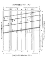
- FIG. 2 shows the amount of current Aa flowing through the first winding 31b of the inner motor 30a when there is no magnetic flux interference, the generated torque Ta (vertical axis) of the inner motor 30a, and the generated torque Tb of the outer motor 30b.
- An inner motor current map showing the relationship with (horizontal axis) is shown.
- FIG. 3 shows the amount of current Aa flowing through the first winding 31b of the inner motor 30a when magnetic flux interference occurs, the generated torque Ta (vertical axis) of the inner motor 30a, and the generated torque Tb (horizontal) of the outer motor 30b.
- An inner motor current map showing the relationship with the axis) is shown. 2 and 3, isoelectric lines extending mainly along the horizontal direction are drawn.
- FIG. 4 shows the amount of current Ab flowing through the second winding 33b of the outer motor 30b when no magnetic flux interference occurs, the generated torque Ta (vertical axis) of the inner motor 30a, and the generated torque Tb (horizontal) of the outer motor 30b.
- An outer motor current map showing the relationship with the shaft) is shown.
- FIG. 5 shows the amount of current Ab flowing through the second winding 33b of the outer motor 30b when magnetic flux interference occurs, the generated torque Ta (vertical axis) of the inner motor 30a, and the generated torque Tb (horizontal) of the outer motor 30b.
- An outer motor current map showing the relationship with the shaft) is shown.
- the isoelectric line mainly extended along the vertical direction is drawn.
- a positive value torque indicates a torque acting in the same rotation direction as the rotation direction of the output shaft 50 when the vehicle moves forward
- a negative value torque indicates a positive value.
- the torque acting in the direction of rotation opposite to the torque of is shown.
- the ECU 90 of the vehicle control apparatus 101 maintains the total torque of the generated torque of the inner motor 30a and the outer motor 30b constant regardless of the occurrence of magnetic flux interference, while maintaining the total torque of the rotating electrical machine 30 as a whole. Control is performed to suppress a decrease in operating efficiency.
- magnetic flux interference may occur because there is a state in which current flows through the first winding 31b and the second winding 33b.
- Each travel mode will be described focusing on the control of the ECU 90 when magnetic flux interference occurs.
- the inner motor 30a has a current value Aa1 ′ (Aa1′ ⁇ Aa1 at the point P1 according to the map of FIG. ) Supply current is required.
- the outer motor 30b requires a supply current of the current value Ab1 ′ (Ab1 ′> Ab1) at the point P1. Therefore, the ECU 90 controls the current value Ab1 ′ in the outer motor 30b to be reduced to the current value Aba while maintaining the torque T1 to the output shaft 50. At this time, the ECU 90 selects a point P1a that becomes the current value Aba on the straight line L1 of the map of FIG. As a result, the inner motor torque is increased and the outer motor torque is decreased.
- the ECU 90 has the operating efficiency of the entire rotating electrical machine 30 when the inner motor 30a operates at the current value Aaa and the outer motor 30b operates at the current value Aba when magnetic flux interference occurs.
- the operation efficiency of the entire rotating electrical machine 30 when the inner motor 30a operates at the current value Aa1 ′ and the outer motor 30b operates at the current value Ab1 ′ is set to be equal to or higher.
- the selection of the point P1a by the ECU 90 is such that when the magnetic flux interference occurs, the operation efficiency of the entire rotating electrical machine 30 when the inner motor 30a is operated at the current value Aaa and the outer motor 30b is operated at the current value Aba is When the inner motor 30a is operated at the current value Aa1 when no interference occurs and the outer motor 30b is operated at the current value Ab1, the operating efficiency of the rotating electrical machine 30 is not decreased or lower than this. It is done to be as close as possible.
- the elements constituting the overall operation efficiency of the rotating electrical machine 30 include the power consumption of the inner motor 30a, the power consumption of the outer motor 30b, the loss in the gear engaging portion between the pinion gear 61 and the driven gear 62 of the output shaft 50, the first The loss in the bearings of the one rotor 31 and the second rotor 32, the loss in the first inverter 21 and the second inverter 22, etc. are included, and the operation efficiency of the entire rotating electrical machine 30 is a combination of these factors.
- the ECU 90 maintains the output torque from the output shaft 50 at T1 while supplying the current values Aaa and Aba to the inner motor 30a and the outer motor 30b, respectively. Thereby, even when magnetic flux interference occurs, the torque T1 to the output shaft 50 is maintained while suppressing a decrease in the operating efficiency of the entire rotating electrical machine 30.
- the ECU 90 operates the engine 10 that is the torque generation source of the inner motor 30a so as to generate the torque Ta2. At this time, the ECU 90 uses the engine efficiency map shown in FIG. 6 to select an engine speed R2 having high operating efficiency with respect to the desired torque Ta2, and operates the engine 10 based on the selected engine speed R2. Control.
- FIG. 6 is an engine efficiency map showing the relationship between the operating efficiency of the engine 10, the engine torque (vertical axis), and the engine speed (horizontal axis).
- the ECU 90 obtains a current value Ab2 at a point P2 on the map that becomes the inner motor torque Ta2 and the outer motor torque Tb2 by using the map of FIG. 4, and the current value Ab2 of the second winding 33b of the stator 33 is obtained. Control is performed to supply current.
- the inner motor 30a an induced current is generated in the first winding 31b of the first rotor 31 that is rotationally driven by the engine 10, and the current value of this induced current is the inner motor torque Ta2 in the map of FIG.
- the ECU 90 controls the supply current value Ab2 'to the outer motor 30b to be reduced to the current value Ab2 while maintaining the torque T2 to the output shaft 50.
- the ECU 90 selects a point P2a that becomes the current value Ab2 on the straight line L2 of the map of FIG. As a result, the outer motor torque is decreased and the inner motor torque is increased.
- the inner motor torque Ta2a is obtained and the outer motor torque Tb2a is obtained.
- the selection of the point P2a by the ECU 90 is such that the operating efficiency of the rotating electrical machine 30 in the state of the point P2a when the magnetic flux interference occurs is equal to or higher than the operating efficiency of the state of the point P2 when the magnetic flux interference occurs. Done. Further, the selection of the point P2a by the ECU 90 is performed so that the operating efficiency of the rotating electrical machine 30 in the state of the point P2a when the magnetic flux interference occurs does not fall below the operating efficiency of the state of the point P2 when the magnetic flux interference does not occur. If it is below, it is also done to be as close as possible to this operating efficiency.
- the ECU 90 uses the map of FIG. 6 to increase the operating efficiency of the engine 10 more than the state of the engine speed R2 and the torque Ta2a while being the engine speed R2 and the torque Ta2a or higher.
- An engine torque Ta2b that does not decrease is selected. From FIG. 6, the torque Ta2a can be selected as the engine torque Ta2b.
- the ECU 90 obtains the outer motor torque Tb2b and the current value Ab2b at the point P2b that becomes the inner motor torque Ta2b on the straight line L2 of the map of FIG. In this case, the point P2b is the same as the point P2a, and the outer motor torque Tb2b and the current value Ab2b are the outer motor torque Tb2a and the current value Ab2, respectively.
- the ECU 90 controls the engine 10 to be supplied with the current value Ab2 to the second winding 33b of the outer motor 30b and to drive the engine 10 at the rotational speed R2 and the engine torque Ta2a.
- the increase in the supply current to the outer motor 30b is suppressed to suppress the decrease in the operation efficiency of the entire rotating electrical machine 30, and the output efficiency is reduced to the output shaft 50 without decreasing the operation efficiency of the engine 10.
- the torque T2 is maintained.
- the current value of the induced current generated in the first winding 31b of the inner motor 30a increases from FIG. 2 and FIG. 3, and the power generation amount increases.
- an induced current is generated in the second winding 33b of the outer motor 30b to which power is not supplied from the battery 23 by the permanent magnet 32c of the second rotor 32 that rotates with the first rotor 31, and a magnetic field in which this induced current is generated. Acts on the permanent magnet 32c to give a negative torque Tb3 to the second rotor 32. Therefore, the inner motor torque Ta3 takes a positive value, and the outer motor torque Tb3 takes a negative value.
- the ECU 90 uses the map of FIG. 6 to select the engine speed R3 that generates the torque Ta3 and has high operating efficiency, and operates the engine 10 based on the selected engine speed R3. Since the engine speed is changed by this control, the rotation speed of the first rotor 31 and the rotation speed of the second rotor 32 that rotates with the first rotor 31 change. For this reason, the outer motor torque Tb3 changes, and the inner motor torque Ta3 changes accordingly. Then, the ECU 90 repeatedly performs the engine speed selection operation as described above using the changed torque and the map of FIG. 6 to obtain the engine speed of the optimum driving efficiency, and at this engine speed The engine 10 is controlled to operate.
- the inner motor torque Ta3o is obtained and the outer motor torque Tb3o is obtained.
- the current value Aa3 at the point P3 that becomes the inner motor torque Ta3o and the outer motor torque Tb3o is generated, and in the outer motor 30b, the current value Ab3 at the point P3 is Will occur.
- the current value at the point P3 in the inner motor 30a is the current value Aa3 '(Aa3' ⁇ Aa3) according to the map of FIG.
- the current value at the point P3 in the outer motor 30b is the current value Ab3 '(Ab3' ⁇ Ab3) according to the map of FIG.
- the ECU 90 controls the inner motor 30a to generate the inner motor torque Ta4 and the outer motor 30b to generate the outer motor torque Tb4 based on information such as the vehicle speed and the engine speed.
- the relationship T4 Ta4 + Tb4 is established.
- the inner motor torque Ta4 is equivalent to the engine torque
- the outer motor torque Tb4 is a field torque due to the rotating magnetic field from the second winding 33b. Therefore, the torques Ta4 and Tb4 are both positive values.
- the ECU 90 obtains a current value Ab4 at a point P4 at which the inner motor torque is Ta4 and the outer motor torque is Tb4 on the straight line L4 in the map of FIG.
- the ECU 90 performs control so that the current of the current value Ab4 is supplied to the second winding 33b of the outer motor 30b.
- the current value at the point P4 becomes the current value Aa4 ′ (Aa4 ′> Aa4), and according to the map of FIG. 5, the current value at the point P4 is The current value Ab4 ′ (Ab4 ′> Ab4). Therefore, the amount of power supplied to the first winding 31b and the second winding 33b increases, that is, the amount of power supplied to the inner motor 30a and the outer motor 30b, both of which are powered. Therefore, the ECU 90 reduces the supply current to the outer motor 30b, which has the larger increase amount of the current supply amount, from the current value Ab4 ′ to the current value Ab4 ′′ while maintaining the torque T4 to the output shaft 50. To control.
- each torque becomes the inner motor torque Ta4a (Ta4a> Ta4) and the outer motor torque Tb4a (Tb4a ⁇ Tb4) at the point P4a where the current value Ab4 ′′ is on the straight line L4.
- the ECU 90 slightly reduces the engine speed to R4a to improve the engine efficiency.
- the current value at the point P4a is Aa4 ′′ (Aa4 ′′> Aa4 ′).
- the ECU 90 determines that the operation efficiency of the entire rotating electrical machine 30 when the inner motor 30a is operated at the current value Aa4 ′′ and the outer motor 30b is operated at the current value Ab4 ′′ is the magnetic flux.
- the current value Ab4 ′′ that is, the point P4a is selected.
- the selection of the point P4a by the ECU 90 is performed when the inner motor 30a operates at the current value Aa4 ′′ and the outer motor 30b operates at the current value Ab4 ′′ when magnetic flux interference occurs.
- the operating efficiency does not fall below the operating efficiency of the entire rotating electrical machine 30 when the inner motor 30a operates at the current value Aa4 and the outer motor 30b operates at the current value Ab4 when magnetic flux interference does not occur. Is performed to be as close as possible to this operational efficiency. Therefore, even when magnetic flux interference occurs, the ECU 90 suppresses a decrease in the operating efficiency of the entire rotating electrical machine 30 while driving the engine 10 with good operating efficiency while maintaining the torque T4 to the output shaft 50.
- torque T5 (T3 ⁇ T5 ⁇ T2) is required for the output shaft 50 in this travel mode.
- the ECU 90 rotationally drives the first rotor 31 by the engine 10 and rotationally drives the second rotor 32 by a rotating magnetic field generated by supplying the electric power of the battery 23 to the first winding 31b.
- the second rotor 32 rotates, an induced current is generated in the second winding 33 b of the stator 33, and the magnetic field generated by this induced current gives a negative value torque to the second rotor 32.
- the ECU 90 controls the inner motor 30a to generate the inner motor torque Ta5 and the outer motor 30b to generate the outer motor torque Tb5 based on information such as the vehicle speed and the engine speed.
- the inner motor torque Ta5 is equivalent to the engine torque
- the outer motor torque Tb5 is an induced current torque due to the induced current of the second winding 33b.
- T5 Ta5 + Tb5 is established.
- the torque Ta5 takes a positive value and the torque Tb5 takes a negative value.
- the supply current of the current value Aa5 ′ (Aa5′ ⁇ Aa5) at the point P5 is Necessary.
- the outer motor 30b according to the map of FIG. 5, an induced current having a current value Ab5 ′ (Ab5 ′ ⁇ Ab5) at the point P5 is generated. Therefore, the amount of power supplied to the inner motor 30a is hardly changed, and the amount of power generated by the outer motor 30b is increased. Since the operation efficiency of the entire rotating electrical machine 30 does not decrease, the ECU 90 continues the control when there is no magnetic flux interference. Therefore, in this traveling mode, when magnetic flux interference occurs, the operation efficiency of the rotating electrical machine 30 as a whole does not decrease. Therefore, the ECU 90 continues the control before the magnetic flux interference occurs even after the magnetic flux interference occurs.
- the vehicle control device 101 is provided so as to be rotatable relative to the engine 10, the rotatable first rotor 31, and the first rotor 31 on the outer side in the radial direction of rotation.
- a rotating electric machine 30 including a second rotor 32 and a stator 33 fixedly arranged on the outer side in the rotational radial direction of the second rotor 32, and an ECU 90 that controls operations of the rotating electric machine 30 and the engine 10.
- the first rotor 31 is mechanically coupled to the engine 10
- the second rotor 32 is mechanically coupled to the vehicle drive mechanism 80.
- the rotating electrical machine 30 includes an inner motor 30 a configured by a first rotor 31 and a second rotor 32, and an outer motor 30 b configured by a second rotor 32 and a stator 33.
- the inner motor 30 a is capable of rotating the second rotor 32 relative to the first rotor 31 by generating a rotating magnetic field by being supplied with an electric current, and the first rotor 31 and the second rotor 32. It is possible to generate electricity by generating an induced current by rotating relatively.
- the outer motor 30 b can rotate the second rotor 32 with respect to the stator 33 by supplying a current and generating a rotating magnetic field, and the second rotor 32 rotates relative to the stator 33.
- the ECU 90 calculates the sum of torques generated by the inner motor 30a and the outer motor 30b when a magnetic field due to a rotating magnetic field or an induced current is generated in each of the inner motor 30a and the outer motor 30b and magnetic flux interference occurs between them.
- the current flowing through the inner motor 30a and the outer motor 30b is controlled so as to suppress a decrease in the efficiency of the rotating electrical machine 30 while maintaining it.
- the vehicle control device 101 can suppress a decrease in driving efficiency without reducing the output of the rotating electrical machine 30 when magnetic flux interference occurs.
- the ECU 90 includes a first map showing a relationship among the current flowing through the inner motor 30a, the generated torque of the inner motor 30a, and the generated torque of the outer motor 30b during control when magnetic flux interference occurs.
- the supply current is controlled using a second map indicating the relationship between the current flowing through the outer motor 30b, the torque generated by the inner motor 30a, and the torque generated by the outer motor 30b.
- the first map and the second map before and after the magnetic flux interference occurs, the current flowing through the inner motor 30a and the outer motor 30b so as not to reduce the operating efficiency of the rotating electrical machine 30 when the magnetic flux interference occurs. It is easy and reliable to control the above.
- the ECU 90 uses the engine efficiency map indicating the relationship between the operation efficiency, torque, and rotation speed of the engine 10 during the control when magnetic flux interference occurs, or the inner motor 30a connected to the engine 10 or The engine 10 is controlled to increase the operating efficiency while generating the torque required from the outer motor 30b.
- magnetic flux interference can occur when current flows through both the first winding 31b of the inner motor 30a and the second winding 33b of the outer motor 30b.
- the ECU 90 determines whether or not magnetic flux interference occurs from the current value and current advance value of the current flowing through the first winding 31b and the current value and current advance value of the current flowing through the second winding 33b. Then, control according to the determination result of the presence or absence of magnetic flux interference may be performed. Note that magnetic flux interference is likely to occur, for example, when the value of the current flowing through the first winding 31b and the second winding 33b is large.
- the ECU 90 includes a map showing a relationship between the inner motor current, the inner motor torque, and the outer motor torque in the inner motor, and the outer motor current, the inner motor torque, and the outer motor torque in the outer motor.
- a map showing the relationship a map that does not depend on the rotational speeds of the inner motor 30a and the outer motor 30b is used, but the map is not limited to this.
- the ECU 90 may use a map for each rotation speed corresponding to various combinations of the rotation speeds of the inner motor 30a and the outer motor 30b for each map. Thus, the ECU 90 can perform more accurate control on the inner motor 30a and the outer motor 30b.
- the two permanent magnets 32c may be integrated, and a row of permanent magnets may be embedded in the circumferential direction in the second core 32a.
- the rotating electrical machine 30 includes the first winding 31b and the first permanent magnet from the radially inner side to the radially outer side as shown in the embodiment (FIG. 1).
- the structure is not limited to the structure in which the above elements are provided in the order of 32b, the second permanent magnet 32c, and the second winding 33b.
- a structure as shown in FIGS. it can.
- the said element is provided in order of the 1st permanent magnet 231b, the 1st winding 232b, the 2nd permanent magnet 232c, and the 2nd winding 33b from radial inside to radial outside. .
- the said element is provided in order of the 1st permanent magnet 231b, the 1st coil
- the said element is provided in order of the 1st coil
- the input shaft 40 is connected to the first rotor 31 and the output shaft 50 is connected to the second rotor 32, but the output shaft 50 is connected to the first rotor 31. May be connected, and the input shaft 40 may be connected to the second rotor 32.
- the first permanent magnets 32b, 231b, 432b and the second permanent magnets 32c, 232c, 333b are used as the field magnets.
- An electromagnet may be used.
- the vehicle control device 101 is not limited to being mounted on a vehicle, but a construction machine, a gasoline engine such as a diesel locomotive, and an internal combustion engine such as a diesel engine and a rotating electrical machine as a power device. It may be mounted on a machine equipped.
Landscapes
- Engineering & Computer Science (AREA)
- Chemical & Material Sciences (AREA)
- Combustion & Propulsion (AREA)
- Transportation (AREA)
- Mechanical Engineering (AREA)
- Power Engineering (AREA)
- Automation & Control Theory (AREA)
- Electric Propulsion And Braking For Vehicles (AREA)
- Hybrid Electric Vehicles (AREA)
Abstract
車両制御装置(101)は、エンジン(10)、回転電機(30)及びECU(90)を備える。回転電機(30)では、第一ロータ(31)がエンジン(10)に機械的に連結され、第二ロータ(32)が出力軸(50)に連結されている。回転電機(30)は、第一ロータ(31)を回転駆動可能なインナーモータ(30a)と、第二ロータ(32)を回転駆動可能なアウターモータ(30b)とを含む。ECU(90)は、インナーモータ(30a)及びアウターモータ(30b)のそれぞれに回転磁界又は誘導電流による磁 界が発生して、互いの間で磁束干渉が生じるとき、インナーモータ(30a)及びアウターモータ(30b)が発生するトルクの和を維持しつつ、回転電機(30)の効率の低下を抑えるようにインナーモータ(30a)及びアウターモータ(30b)を流れる電流を制御する。
Description
この発明は、車両制御装置に係り、特に、内燃機関及び回転電機を用いて走行する車両の車両制御装置に関する。
内燃機関及び回転電機を用いて走行するハイブリッド自動車では、例えば特許文献1に示されるように、2つの回転電機と1つのエンジン(内燃機関)とを備えるものがある。第一回転電機の回転子はエンジンの出力軸に連結され、第二回転電機の回転子は車両の車輪軸の差動装置に連結されている。そして、第二回転電機は、エンジン及び第一回転電機に連結されていない。第一回転電機は、エンジンの駆動により発電する発電機としての機能を有する。第二回転電機は、車輪を回転駆動する電動機としての機能を有する。
また、近年、上記の第一回転電機及び第二回転電機を一体化して1つの回転電機とした二重ロータ型の回転電機が、省スペース化をもたらすため、上述のようなハイブリッド自動車に採用されている。
二重ロータ型の回転電機は、エンジンの出力軸が連結される回転子であり且つ最も内側に配置される内ロータと、内ロータの径方向外側に配置され且つ差動装置に連結される外ロータと、外ロータの径方向外側に配置されてケーシング等に固定されたステータとを有している。例えば、内ロータ及びステータには三相巻線が巻回され、外ロータには永久磁石が設けられている。三相巻線は、インバータに電気的に接続されており、インバータを介して電力の供給を受けること及び発生した電力をインバータに送ることができる。
内ロータ及び外ロータは1つの内側回転電機を構成し、外ロータ及びステータは1つの外側回転電機を構成する。
二重ロータ型の回転電機は、エンジンの出力軸が連結される回転子であり且つ最も内側に配置される内ロータと、内ロータの径方向外側に配置され且つ差動装置に連結される外ロータと、外ロータの径方向外側に配置されてケーシング等に固定されたステータとを有している。例えば、内ロータ及びステータには三相巻線が巻回され、外ロータには永久磁石が設けられている。三相巻線は、インバータに電気的に接続されており、インバータを介して電力の供給を受けること及び発生した電力をインバータに送ることができる。
内ロータ及び外ロータは1つの内側回転電機を構成し、外ロータ及びステータは1つの外側回転電機を構成する。
二重ロータ型の回転電機では、例えば車両に高速状態での加速が必要な場合、ステータに電力を供給することで三相巻線から発生する回転磁界の作用により外側回転電機を回転駆動する回転トルクに加え、内側回転電機を回転駆動する回転トルクが必要になる。この2つの回転トルクが協調して高い回転トルクを車両に与えることができる。このとき、内側回転電機では、高い回転トルクを得るために、内ロータに電力が供給されると共に内ロータがエンジンによって回転駆動される。その結果、内ロータの三相巻線が生じる回転磁界の磁束と、ステータの三相巻線が生じる回転磁界の磁束とが、干渉し合い、内側回転電機及び外側回転電機の回転トルクを低下させることがある。この回転トルクの低下を補うためには、内ロータ及びステータの三相巻線に供給する電流を増加させる必要があり、それにより、二重ロータ型の回転電機での運転効率が低下するという問題が生じる。
本発明は上記のような問題を解決するためになされたものであり、二重ロータ型の回転電機において磁束干渉が生じた場合の回転電機の効率の低下を抑える車両制御装置を提供することを目的とする。
上記の課題を解決するために、本発明に係る車両制御装置は、内燃機関と、回転可能な第一回転子、第一回転子に対して回転半径方向外側で相対回転可能に設けられる第二回転子、及び第二回転子の回転半径方向外側で固定配設される固定子を含む回転電機と、回転電機及び内燃機関の動作を制御する制御部とを備え、第一回転子及び第二回転子のうちの一方が、内燃機関に機械的に連結されると共に、第一回転子及び第二回転子のうちの他方が、車両駆動機構に機械的に連結され、回転電機は、第一回転子及び第二回転子によって構成される第一回転電機部と、第二回転子及び固定子によって構成される第二回転電機部とを含み、第一回転電機部は、電流が供給されて回転磁界を発生することによって第一回転子又は第二回転子を第二回転子又は第一回転子に対して相対的に回転駆動することが可能であり、第一回転子及び第二回転子が相対的に回転することによって誘導電流を発生して発電することが可能であり、第二回転電機部は、電流が供給されて回転磁界を発生することによって第二回転子を固定子に対して回転駆動することが可能であり、第二回転子が固定子に対して相対的に回転することによって誘導電流を発生して発電することが可能であり、制御部は、第一回転電機部及び第二回転電機部のそれぞれに回転磁界又は誘導電流による磁界が発生して、互いの間で磁束干渉が生じるとき、第一回転電機部及び第二回転電機部が発生するトルクの和を維持しつつ、回転電機の効率の低下を抑えるように第一回転電機部及び第二回転電機部を流れる電流を制御する。
本発明に係る車両制御装置によれば、磁束干渉が生じた場合の二重ロータ型回転電機の効率の低下を抑えることが可能になる。
以下、本発明の実施の形態について添付図面に基づいて説明する。
まず、本発明の実施の形態に係る車両制御装置101の構成を説明する。なお、本実施の形態では、車両制御装置101は、ハイブリッド自動車に搭載されるものとして説明する。
図1を参照すると、車両制御装置101は、内燃機関であるエンジン10と、三相交流電力によって動作する二重ロータ型モータである回転電機30とをハイブリッド自動車の動力装置として備えている。回転電機30は、回転可能な第一ロータ31、回転可能な第二ロータ32、及び回転電機30の図示しないケーシングに固定して配設されたステータ33とを備えている。ここで、第一ロータ31は第一回転子を構成し、第二ロータ32は第二回転子を構成し、ステータ33は固定子を構成している。
まず、本発明の実施の形態に係る車両制御装置101の構成を説明する。なお、本実施の形態では、車両制御装置101は、ハイブリッド自動車に搭載されるものとして説明する。
図1を参照すると、車両制御装置101は、内燃機関であるエンジン10と、三相交流電力によって動作する二重ロータ型モータである回転電機30とをハイブリッド自動車の動力装置として備えている。回転電機30は、回転可能な第一ロータ31、回転可能な第二ロータ32、及び回転電機30の図示しないケーシングに固定して配設されたステータ33とを備えている。ここで、第一ロータ31は第一回転子を構成し、第二ロータ32は第二回転子を構成し、ステータ33は固定子を構成している。
第一ロータ31は、第一ロータ31、第二ロータ32及びステータ33の中で最も中心側に配置されている。第一ロータ31の回転軸を構成する入力軸40は、エンジン10のエンジン出力軸11に電磁クラッチ41を介して機械的に連結されている。電磁クラッチ41は、入力軸40とエンジン出力軸11とを、動力伝達を可能にする連結状態と動力伝達を遮断する切断状態とにするように選択的に動作する。なお、この機械的に連結されるとは、入力軸40とエンジン出力軸11とが、電磁クラッチ41のみを介して互いに連結される場合と、電磁クラッチ41に加えて、増速機、減速機のような変速機構等を介して連結される場合とを含む。
第一ロータ31は、入力軸40の外周を囲むように入力軸40に一体回転可能に設けられた円筒状の第一コア31aと、第一コア31a内で周方向に沿って設けられた第一巻線31bとを有している。第一巻線31bは、三相巻線である。
第二ロータ32は、第一ロータ31の外周を囲むように第一ロータ31の径方向外側に設けられ且つ円筒状をした第二コア32aと、第一コア31aに対向する第二コア32aの内周面近傍に周方向に沿って埋め込まれた第一永久磁石32bと、第二コア32aにおける内周面と反対側の外周面近傍に周方向に沿って埋め込まれた第二永久磁石32cとを有している。つまり、第一永久磁石32bは、第一巻線31bと対向して位置している。第二コア32aは、入力軸40及び第一ロータ31の外周を囲むように設けられ且つ入力軸40によって図示しない軸受を介して回転自在に支持される有底円筒状の支持ハウジング32dによって、保持されている。第二コア32aと支持ハウジング32dとは、一体となって、入力軸40及び第一ロータ31の周囲をこれらに対して相対的に回転することができる。
第二ロータ32は、第一ロータ31の外周を囲むように第一ロータ31の径方向外側に設けられ且つ円筒状をした第二コア32aと、第一コア31aに対向する第二コア32aの内周面近傍に周方向に沿って埋め込まれた第一永久磁石32bと、第二コア32aにおける内周面と反対側の外周面近傍に周方向に沿って埋め込まれた第二永久磁石32cとを有している。つまり、第一永久磁石32bは、第一巻線31bと対向して位置している。第二コア32aは、入力軸40及び第一ロータ31の外周を囲むように設けられ且つ入力軸40によって図示しない軸受を介して回転自在に支持される有底円筒状の支持ハウジング32dによって、保持されている。第二コア32aと支持ハウジング32dとは、一体となって、入力軸40及び第一ロータ31の周囲をこれらに対して相対的に回転することができる。
ステータ33は、第二ロータ32の外周を囲むように第二ロータ32の径方向外側に設けられ且つ円筒状をしたステータコア33aと、ステータコア33aにおける第二コア32aと対向する内周面近傍に周方向に沿って設けられた第二巻線33bとを有している。第二巻線33bは、第二永久磁石32cと対向して位置し、三相巻線である。ステータコア33aは、回転電機30の図示しないケーシングに固定されている。
よって、回転電機30では、第一ロータ31及び第二ロータ32からなり且つ内側に位置する1つのモータであるインナーモータ30aが形成され、第二ロータ32及びステータ33からなり且つ外側に位置する1つのモータであるアウターモータ30bが形成される。ここで、インナーモータ30aは第一回転電機部を構成し、アウターモータ30bは第二回転電機部を構成している。
なお、図1では、第一ロータ31、第二ロータ32及びステータ33の断面が模式的に示されている。
よって、回転電機30では、第一ロータ31及び第二ロータ32からなり且つ内側に位置する1つのモータであるインナーモータ30aが形成され、第二ロータ32及びステータ33からなり且つ外側に位置する1つのモータであるアウターモータ30bが形成される。ここで、インナーモータ30aは第一回転電機部を構成し、アウターモータ30bは第二回転電機部を構成している。
なお、図1では、第一ロータ31、第二ロータ32及びステータ33の断面が模式的に示されている。
また、第二ロータ32の支持ハウジング32dには、出力軸50が一体に回転するように機械的に連結されている。出力軸50の端部には、ピニオンギヤ61が一体に回転するように取り付けられている。ピニオンギヤ61は、ドリブンギヤ62とギヤ係合している。さらに、ドリブンギヤ62は、図示しない車両の車輪にデファレンシャルギヤを介して接続された駆動軸71に、一体に回転するように取り付けられている。よって、第二ロータ32及び支持ハウジング32dが共に回転することによって、駆動軸71が回転駆動され、それにより車輪が回転駆動される。なお、第二ロータ32の支持ハウジング32dは、駆動軸71に対して、出力軸50、ピニオンギヤ61及びドリブンギヤ62に加えて、変速機等の機械式の動力伝達機構を介して機械的に連結されていてもよい。ここで、出力軸50、ピニオンギヤ61、ドリブンギヤ62及び駆動軸71は、車両駆動機構80を構成している。
また、車両制御装置101は、直流電力を充放電可能なバッテリ23と、バッテリ23に電気的に接続された第一インバータ21及び第二インバータ22とを備えている。第一インバータ21及び第二インバータ22は、バッテリ23から供給された直流電力を三相交流電力に変換することができるほか、三相交流電力を直流電力に変換しバッテリ23に供給することができる。第一インバータ21及び第二インバータ22は、後述するコントロールユニット(以下、ECUと呼ぶ)90によって、それらの動作の制御を受ける。ここで、ECU90は、制御部を構成している。
第一インバータ21は、入力軸40の周りに取り付けられたスリップリング機構24に電気的に接続されている。第一インバータ21から出力される三相交流電力は、スリップリング機構24を介して、入力軸40に沿って設けられた図示しない導電体に伝達され、この導電体を通って第一ロータ31の第一巻線31bに供給される。一方、第一巻線31bで交流電流である誘導電流が発生すると、この誘導電流は、導電体及びスリップリング機構24を介して第一インバータ21に供給され、第一インバータ21で直流電流に変換された後にバッテリ23に供給される。
第二インバータ22は、ステータ33の第二巻線33bに電気的に接続されている。これにより、第二インバータ22から出力される三相交流電力は、第二巻線33bに供給される。一方、第二巻線33bで誘導電流が発生すると、この誘導電流は、第二インバータ22に供給され、第二インバータ22で直流電流に変換された後にバッテリ23に供給される。
ECU90は、第一インバータ21及び第二インバータ22を制御することによって、回転電機30の第一ロータ31の第一巻線31b及びステータ33の第二巻線33bへの電力供給を制御する。
また、ECU90は、エンジン10のトルクを検知するエンジントルクセンサ10aと、エンジン10の回転数を検知するエンジン回転数センサ10bとに電気的に接続され、検知されたエンジントルク情報及びエンジン回転数情報を取得するように構成されている。さらに、ECU90は、車両の運転席のアクセルの開度を検知するアクセル開度センサ12に電気的に接続され、検知されたアクセル開度情報を取得するように構成されている。さらにまた、ECU90は、回転電機30の第二ロータ32の回転数を検知するモータ回転数センサ13に電気的に接続され、検知されたロータ回転数情報を取得するように構成されている。
また、ECU90は、エンジン10のトルクを検知するエンジントルクセンサ10aと、エンジン10の回転数を検知するエンジン回転数センサ10bとに電気的に接続され、検知されたエンジントルク情報及びエンジン回転数情報を取得するように構成されている。さらに、ECU90は、車両の運転席のアクセルの開度を検知するアクセル開度センサ12に電気的に接続され、検知されたアクセル開度情報を取得するように構成されている。さらにまた、ECU90は、回転電機30の第二ロータ32の回転数を検知するモータ回転数センサ13に電気的に接続され、検知されたロータ回転数情報を取得するように構成されている。
ECU90は、アクセル開度センサ12、モータ回転数センサ13、エンジントルクセンサ10a及びエンジン回転数センサ10bから受け取る情報を使用して、インナーモータ30a及びアウターモータ30bのトルク、第二ロータ32及び出力軸50の回転数、エンジントルク並びにエンジン回転数を決定し、それにより、第一インバータ21、第二インバータ22、インナーモータ30a、アウターモータ30b及びエンジン10の動作を制御する。
また、ECU90は、電磁クラッチ41に電気的に接続されている。ECU90は、電磁クラッチ41に供給する電力を制御して、電磁クラッチ41の断接動作を制御する。
そして、上述のような車両制御装置101は、エンジン10の駆動力が回転電機30の駆動軸である入力軸40を直接的に駆動するためにのみ用いられるレンジエクステンダー(RE)方式のハイブリッド自動車を構成している。
また、ECU90は、電磁クラッチ41に電気的に接続されている。ECU90は、電磁クラッチ41に供給する電力を制御して、電磁クラッチ41の断接動作を制御する。
そして、上述のような車両制御装置101は、エンジン10の駆動力が回転電機30の駆動軸である入力軸40を直接的に駆動するためにのみ用いられるレンジエクステンダー(RE)方式のハイブリッド自動車を構成している。
次に、本発明の実施の形態に係る車両制御装置101の動作を説明する。
図1を参照すると、車両制御装置101は、車両制御装置101を搭載するハイブリッド自動車を、回転電機30の出力軸50からの回転駆動力つまりトルクによって走行させる。このとき、出力軸50からのトルクは、ピニオンギヤ61、ドリブンギヤ62及び駆動軸71を介して、図示しない車両の車輪に伝達し、車両を走行させる。なお、出力軸50からのトルクは、回転電機30のインナーモータ30aが発生するトルクとアウターモータ30bの発生するトルクとを合計したものとなる。
図1を参照すると、車両制御装置101は、車両制御装置101を搭載するハイブリッド自動車を、回転電機30の出力軸50からの回転駆動力つまりトルクによって走行させる。このとき、出力軸50からのトルクは、ピニオンギヤ61、ドリブンギヤ62及び駆動軸71を介して、図示しない車両の車輪に伝達し、車両を走行させる。なお、出力軸50からのトルクは、回転電機30のインナーモータ30aが発生するトルクとアウターモータ30bの発生するトルクとを合計したものとなる。
さらに、車両制御装置101は、バッテリ23の電力を使用することのみによって出力軸50を回転駆動し車両を走行させるEVモード走行形態と、エンジン10の動力を使用して入力軸40を回転駆動しつつ車両を走行させるREモード走行形態とを適宜選択して、車両の走行を制御する。なお、REモード走行形態では、バッテリ23の電力を使用する場合も使用しない場合もある。さらに、車両制御装置101は、REモード走行形態において、低速加速走行、低速巡航走行、高速加速走行及び高速巡航走行の4つの走行形態に応じて、その制御を変更する。
以下に、(1)EVモード走行形態、(2)低速加速時のREモード走行形態、(3)低速巡航時のREモード走行形態、(4)高速加速時のREモード走行形態、及び(5)高速巡航時のREモード走行形態の各走行形態における車両制御装置101の制御内容を説明する。
以下に、(1)EVモード走行形態、(2)低速加速時のREモード走行形態、(3)低速巡航時のREモード走行形態、(4)高速加速時のREモード走行形態、及び(5)高速巡航時のREモード走行形態の各走行形態における車両制御装置101の制御内容を説明する。
(1)EVモード走行形態
この走行形態は、バッテリ23の充電率が所定値以上の場合に実施される車両の走行形態である。
ECU90は、モータ回転数センサ13から得られる車速、アクセル開度センサ12から得られるアクセル開度等の情報から車両に要求される走行状態を判定する。判定した走行状態に基づき、ECU90は、回転電機30のインナーモータ30a及びアウターモータ30bに要求される回転数、トルク及び電流値を決定する。なお、インナーモータ30aの回転数は、第一ロータ31と第二ロータ32との回転数差に相当し、インナーモータ30aのトルクは、エンジン10の発生トルクに相当する。アウターモータ30bの回転数は、第二ロータ32及び出力軸50の回転数に相当し、アウターモータ30bのトルクは、第二ロータ32とステータ33との間で磁界により発生するトルクに相当する。
この走行形態は、バッテリ23の充電率が所定値以上の場合に実施される車両の走行形態である。
ECU90は、モータ回転数センサ13から得られる車速、アクセル開度センサ12から得られるアクセル開度等の情報から車両に要求される走行状態を判定する。判定した走行状態に基づき、ECU90は、回転電機30のインナーモータ30a及びアウターモータ30bに要求される回転数、トルク及び電流値を決定する。なお、インナーモータ30aの回転数は、第一ロータ31と第二ロータ32との回転数差に相当し、インナーモータ30aのトルクは、エンジン10の発生トルクに相当する。アウターモータ30bの回転数は、第二ロータ32及び出力軸50の回転数に相当し、アウターモータ30bのトルクは、第二ロータ32とステータ33との間で磁界により発生するトルクに相当する。
そして、ECU90は、エンジン10を停止させた状態とすると共に、電磁クラッチ41を切断してエンジン10と入力軸40との間の動力伝達を遮断する。さらに、ECU90は、第二インバータ22を制御して、バッテリ23の直流電力を三相交流電力に変換し三相交流電力を回転電機30のステータ33の第二巻線33bに供給する。この結果、第二巻線33bの三相交流電力が回転磁界を発生し、この回転磁界が、第二永久磁石32cに作用して第二ロータ32を支持ハウジング32dと共に回転させる。つまり、回転電機30のアウターモータ30bが駆動する。これにより、出力軸50が回転駆動され、車両が走行する。この走行形態では、バッテリ23の電力を用いたアウターモータ30bによる力行が実施されることになる。
なお、第二ロータ32の回転駆動力が不足する場合には、ECU90は、電磁クラッチ41を接続状態として第一ロータ31を回転方向に固定すると共に、第一インバータ21を介してバッテリ23の電力を回転電機30の第一ロータ31の第一巻線31bにも供給する。これにより、第一巻線31bの三相交流電力によって発生する回転磁界が、第二永久磁石32bに作用して第二ロータ32に回転駆動力を付加する。
なお、第二ロータ32の回転駆動力が不足する場合には、ECU90は、電磁クラッチ41を接続状態として第一ロータ31を回転方向に固定すると共に、第一インバータ21を介してバッテリ23の電力を回転電機30の第一ロータ31の第一巻線31bにも供給する。これにより、第一巻線31bの三相交流電力によって発生する回転磁界が、第二永久磁石32bに作用して第二ロータ32に回転駆動力を付加する。
(2)低速加速時のREモード走行形態
この走行形態は、バッテリ23の充電率が所定値未満の場合に実施される車両の低速加速走行時の走行形態である。
ECU90は、車速、アクセル開度等の情報から車両に要求される低速加速走行状態を判定する。判定結果に基づき、ECU90は、回転電機30のインナーモータ30a及びアウターモータ30bに要求される回転数、トルク及び電流値を決定する。
この走行形態は、バッテリ23の充電率が所定値未満の場合に実施される車両の低速加速走行時の走行形態である。
ECU90は、車速、アクセル開度等の情報から車両に要求される低速加速走行状態を判定する。判定結果に基づき、ECU90は、回転電機30のインナーモータ30a及びアウターモータ30bに要求される回転数、トルク及び電流値を決定する。
そして、ECU90は、エンジン10を稼働させた状態とすると共に、電磁クラッチ41を接続してエンジン10と入力軸40とを動力伝達可能な状態にする。さらに、ECU90は、第二インバータ22を制御してバッテリ23の電力を回転電機30のステータ33に供給する。
このとき、インナーモータ30aでは、エンジン10によって、入力軸40と共に第一ロータ31が回転駆動される。第一ロータ31の第一巻線31bは、第二ロータ32の永久磁石32bが生成する磁場内を移動することによって、誘導電流を内部に発生する。三相交流電流である誘導電流は、第一コア31a及び入力軸40に設けられた導電体を通ってスリップリング機構24に送られ、さらに、スリップリング機構24から第一インバータ21に送られて直流電流に変換された後に、バッテリ23に充電される。また、第二ロータ32の永久磁石32bは、第一巻線31b内の誘導電流が発生する磁場によって引き付けられ、それにより、第二ロータ32は、第一ロータ31と同一の回転方向に引っ張られるようにして連れ回りする。この際、第二ロータ32は、エンジン10の発生トルクに相当する回転力を受けて回転する。
このとき、インナーモータ30aでは、エンジン10によって、入力軸40と共に第一ロータ31が回転駆動される。第一ロータ31の第一巻線31bは、第二ロータ32の永久磁石32bが生成する磁場内を移動することによって、誘導電流を内部に発生する。三相交流電流である誘導電流は、第一コア31a及び入力軸40に設けられた導電体を通ってスリップリング機構24に送られ、さらに、スリップリング機構24から第一インバータ21に送られて直流電流に変換された後に、バッテリ23に充電される。また、第二ロータ32の永久磁石32bは、第一巻線31b内の誘導電流が発生する磁場によって引き付けられ、それにより、第二ロータ32は、第一ロータ31と同一の回転方向に引っ張られるようにして連れ回りする。この際、第二ロータ32は、エンジン10の発生トルクに相当する回転力を受けて回転する。
アウターモータ30bでは、ステータ33の第二巻線33bから発生する回転磁界の作用によって、支持ハウジング32dと共に第二ロータ32が第一ロータ31と同方向に回転駆動される。つまり、第二ロータ32は、回転磁界の発生トルクを受けて回転する。
よって、上記のようなインナーモータ30aでの発生トルクとアウターモータ30bでの発生トルクとを受けた状態で第二ロータ32及び出力軸50が回転駆動され、それにより車両が加速走行する。
この走行形態では、エンジン10の動力を用いたインナーモータ30aによる発電とバッテリ23の電力を用いたアウターモータ30bによる力行とが実施されることになる。
よって、上記のようなインナーモータ30aでの発生トルクとアウターモータ30bでの発生トルクとを受けた状態で第二ロータ32及び出力軸50が回転駆動され、それにより車両が加速走行する。
この走行形態では、エンジン10の動力を用いたインナーモータ30aによる発電とバッテリ23の電力を用いたアウターモータ30bによる力行とが実施されることになる。
(3)低速巡航時のREモード走行形態
この走行形態は、バッテリ23の充電率が所定値未満の場合に実施される車両の低速巡航走行時の走行形態である。
ECU90は、車速、アクセル等の情報から車両に要求される低速巡航状態を判定する。判定結果に基づき、ECU90は、回転電機30のインナーモータ30a及びアウターモータ30bに要求される回転数、トルク及び電流値を決定する。
この走行形態は、バッテリ23の充電率が所定値未満の場合に実施される車両の低速巡航走行時の走行形態である。
ECU90は、車速、アクセル等の情報から車両に要求される低速巡航状態を判定する。判定結果に基づき、ECU90は、回転電機30のインナーモータ30a及びアウターモータ30bに要求される回転数、トルク及び電流値を決定する。
そして、ECU90は、エンジン10を稼働させた状態とする共に電磁クラッチ41を接続状態にするが、バッテリ23の電力を回転電機30のステータ33にも第一ロータ31にも供給しない。このとき、インナーモータ30aでは、エンジン10によって、第一ロータ31が回転駆動される。これにより、第一ロータ31の第一巻線31b内には、誘導電流が発生し、発生した誘導電流は、スリップリング機構24及び第一インバータ21を通って、直流電力に変換された後にバッテリ23に充電される。また、第二ロータ32の永久磁石32bが、第一巻線31b内の誘導電流が発生する磁場によって引き付けられるため、第二ロータ32は、第一ロータ31と同一の回転方向に、エンジン10の発生トルクに相当する回転力を受けて回転する。
さらに、第二ロータ32がステータ33に対して相対的に回転するため、第二ロータ32の永久磁石32cは、ステータ33の第二巻線33bの内側周囲を旋回する磁場を生成する。これにより、第二巻線33b内には、誘導電流が発生し、この誘導電流は、第二インバータ22に送られて直流電流に変換された後に、バッテリ23に充電される。また、第二巻線33b内の誘導電流が発生する磁場が永久磁石32cに作用して、第二ロータ32に回転方向と反対方向の回転トルクを発生させる。
これにより、第二ロータ32は、車両が低速巡航走行状態を維持するように一定回転数での回転動作を継続する。
この走行形態では、エンジン10の動力を用いたインナーモータ30a及びアウターモータ30bによる発電が実施されることになる。
これにより、第二ロータ32は、車両が低速巡航走行状態を維持するように一定回転数での回転動作を継続する。
この走行形態では、エンジン10の動力を用いたインナーモータ30a及びアウターモータ30bによる発電が実施されることになる。
(4)高速加速時のREモード走行形態
この走行形態は、バッテリ23の充電率が所定値未満の場合に実施される車両の高速加速走行時の走行形態である。
ECU90は、車速、アクセル開度等の情報から車両に要求される高速加速状態を判定する。判定結果に基づき、ECU90は、回転電機30のインナーモータ30a及びアウターモータ30bに要求される回転数、トルク及び電流値を決定する。
この走行形態は、バッテリ23の充電率が所定値未満の場合に実施される車両の高速加速走行時の走行形態である。
ECU90は、車速、アクセル開度等の情報から車両に要求される高速加速状態を判定する。判定結果に基づき、ECU90は、回転電機30のインナーモータ30a及びアウターモータ30bに要求される回転数、トルク及び電流値を決定する。
そして、ECU90は、エンジン10を稼働させた状態とすると共に電磁クラッチ41を接続状態にする。さらに、ECU90は、第一インバータ21と第二インバータ22とを制御して、バッテリ23の電力を回転電機30の第一ロータ31の第一巻線31bとステータ33の第二巻線33bとにそれぞれ供給する。
このとき、アウターモータ30bでは、第二巻線33b内を流れる三相交流電流が回転磁界を発生し、この回転磁界は、永久磁石32cに作用して第二ロータ32に回転トルクを与える。
このとき、アウターモータ30bでは、第二巻線33b内を流れる三相交流電流が回転磁界を発生し、この回転磁界は、永久磁石32cに作用して第二ロータ32に回転トルクを与える。
また、インナーモータ30aでは、エンジン10によって回転移動される第一巻線31b内を流れる三相交流電流が、第二ロータ32の内周に沿って旋回する回転磁界を発生し、この旋回する回転磁界は、永久磁石32bに作用してエンジン10の発生トルクを第二ロータ32に伝達する。このとき、回転移動している第一ロータ31の第一巻線31bに回転磁界を発生させることによって、出力軸50を介して高負荷を受ける第二ロータ32に対してでも、高い回転速度で回転させつつ、エンジン10の発生トルクを作用させることができる。
上述のように、インナーモータ30aにおけるエンジン10の回転駆動力及び第一巻線31bから発生する回転磁界と、アウターモータ30bにおける第二巻線33bから発生する回転磁界とが、協働して作用して第二ロータ32を高速加速状態で回転させ、これにより、高速走行状態の車両がさらに加速するように走行する。
この走行形態では、バッテリ23の電力及びエンジン10の動力を用いたインナーモータ30a及びアウターモータ30bによる力行が実施されることになる。
上述のように、インナーモータ30aにおけるエンジン10の回転駆動力及び第一巻線31bから発生する回転磁界と、アウターモータ30bにおける第二巻線33bから発生する回転磁界とが、協働して作用して第二ロータ32を高速加速状態で回転させ、これにより、高速走行状態の車両がさらに加速するように走行する。
この走行形態では、バッテリ23の電力及びエンジン10の動力を用いたインナーモータ30a及びアウターモータ30bによる力行が実施されることになる。
(5)高速巡航時のREモード走行形態
この走行形態は、バッテリ23の充電率が所定値未満の場合に実施される車両の高速巡航走行時の走行形態である。
ECU90は、車速、アクセル開度等の情報から車両に要求される高速巡航状態を判定する。判定結果に基づき、ECU90は、回転電機30のインナーモータ30a及びアウターモータ30bに要求される回転数、トルク及び電流値を決定する。
この走行形態は、バッテリ23の充電率が所定値未満の場合に実施される車両の高速巡航走行時の走行形態である。
ECU90は、車速、アクセル開度等の情報から車両に要求される高速巡航状態を判定する。判定結果に基づき、ECU90は、回転電機30のインナーモータ30a及びアウターモータ30bに要求される回転数、トルク及び電流値を決定する。
そして、ECU90は、エンジン10を稼働させた状態とする共に電磁クラッチ41を接続状態にし、さらに、第一インバータ21を制御してバッテリ23の電力を回転電機30の第一ロータ31に供給する。このとき、インナーモータ30aでは、第一巻線31b内を流れる三相交流電流が回転磁界を発生し、この回転磁界は、永久磁石32bに作用してエンジン10の発生トルクを第二ロータ32に伝達する。これにより、出力軸50を介して高負荷を受ける第二ロータ32に対して、高い回転速度で回転させつつ、エンジン10の発生トルクを作用させることができる。
また、第二ロータ32がステータ33に対して相対的に回転するため、ステータ33の第二巻線33b内には誘導電流が発生し、この誘導電流は、第二インバータ22を経由してバッテリ23に充電される。第二巻線33b内の誘導電流が発生する磁場は、永久磁石32cに作用して、第二ロータ32に回転方向と反対方向の回転トルクを発生させる。
よって、第二ロータ32は、インナーモータ30aにおけるエンジン10の回転駆動力及び第一巻線31bから発生する回転磁界と、アウターモータ30bにおける第二巻線33bから発生する磁場とを受けつつ、車両が高速巡航走行状態を維持するように一定回転数での回転動作を継続する。
この走行形態では、バッテリ23の電力及びエンジン10の動力を用いたインナーモータ30aによる力行と、アウターモータ30bによる発電とが、実施されることになる。
よって、第二ロータ32は、インナーモータ30aにおけるエンジン10の回転駆動力及び第一巻線31bから発生する回転磁界と、アウターモータ30bにおける第二巻線33bから発生する磁場とを受けつつ、車両が高速巡航走行状態を維持するように一定回転数での回転動作を継続する。
この走行形態では、バッテリ23の電力及びエンジン10の動力を用いたインナーモータ30aによる力行と、アウターモータ30bによる発電とが、実施されることになる。
上述のような各走行形態で車両を走行させるためには、回転電機30の出力軸50に所定のトルク(インナーモータ30aのトルクとアウターモータ30bのトルクとの合計トルク)が要求される。そして、ECU90は、エンジン10の回転数と、第一インバータ21及び第二インバータ22を介したインナーモータ30a及びアウターモータ30bへの電流供給量とを調節して、インナーモータ30a及びアウターモータ30bそれぞれの発生トルクを制御し、それにより出力軸50へ出力するトルクを制御する。
また、回転電機30の動作時において、第一ロータ31の第一巻線31bとステータ33の第二巻線33bとのいずれにも三相交流電流が流れる場合、第一巻線31b及び第二巻線33bの三相交流電流それぞれが発生する回転磁界が互いに干渉する磁束干渉が、生じることがある。磁束干渉が生じると、第一巻線31b及び第二巻線33bを流れる電流量に対応するインナーモータ30a及びアウターモータ30bの発生トルクが、変動する。
例えば、図2には、磁束干渉が生じていない場合のインナーモータ30aの第一巻線31bを流れる電流量Aaと、インナーモータ30aの発生トルクTa(縦軸)及びアウターモータ30bの発生トルクTb(横軸)との関係を表すインナーモータ電流マップが示されている。図3には、磁束干渉が生じている場合のインナーモータ30aの第一巻線31bを流れる電流量Aaと、インナーモータ30aの発生トルクTa(縦軸)及びアウターモータ30bの発生トルクTb(横軸)との関係を表すインナーモータ電流マップが示されている。なお、図2及び図3のマップ上には、主に横方向に沿って延在する等電流線が描かれている。
図4には、磁束干渉が生じていない場合のアウターモータ30bの第二巻線33bを流れる電流量Abと、インナーモータ30aの発生トルクTa(縦軸)及びアウターモータ30bの発生トルクTb(横軸)との関係を表すアウターモータ電流マップが示されている。図5には、磁束干渉が生じている場合のアウターモータ30bの第二巻線33bを流れる電流量Abと、インナーモータ30aの発生トルクTa(縦軸)及びアウターモータ30bの発生トルクTb(横軸)との関係を表すアウターモータ電流マップが示されている。なお、図4及び図5のマップ上には、主に縦方向に沿って延在する等電流線が描かれている。
さらに、図2~図5のマップにおいて、正の値のトルクは、車両の前進時の出力軸50の回転方向と同じ回転方向に作用するトルクを示し、負の値のトルクは、正の値のトルクと反対の回転方向に作用するトルクを示す。
さらに、図2~図5のマップにおいて、正の値のトルクは、車両の前進時の出力軸50の回転方向と同じ回転方向に作用するトルクを示し、負の値のトルクは、正の値のトルクと反対の回転方向に作用するトルクを示す。
図2と図3とを比較した場合、及び、図4と図5とを比較した場合のいずれにおいても、磁束干渉の発生後でインナーモータ30a及びアウターモータ30bの発生トルクを維持しようとしたとき、各巻線を流れる電流量に変化が生じる。そして、場合によっては、巻線に供給する電流量の増加や巻線で発生する発電量の減少が生じ、回転電機30全体の運転効率が低下することがある。
しかしながら、本実施の形態の車両制御装置101のECU90は、磁束干渉の発生の有無にかかわらず、インナーモータ30a及びアウターモータ30bの発生トルクの合計トルクを一定に維持しつつ、回転電機30全体の運転効率の低下を抑制するように制御する。
そして、上述で説明した走行形態(1)~(5)のいずれにおいても、第一巻線31b及び第二巻線33bに電流が流れる状態があるため、磁束干渉が発生し得る。各走行形態について、磁束干渉が生じる場合のECU90の制御を中心に説明する。
しかしながら、本実施の形態の車両制御装置101のECU90は、磁束干渉の発生の有無にかかわらず、インナーモータ30a及びアウターモータ30bの発生トルクの合計トルクを一定に維持しつつ、回転電機30全体の運転効率の低下を抑制するように制御する。
そして、上述で説明した走行形態(1)~(5)のいずれにおいても、第一巻線31b及び第二巻線33bに電流が流れる状態があるため、磁束干渉が発生し得る。各走行形態について、磁束干渉が生じる場合のECU90の制御を中心に説明する。
(1)EVモードによる走行形態
図1~図5をあわせて参照すると、この走行形態において、出力軸50にトルクT1が要求される。さらに、バッテリ23の電力によって、インナーモータ30a及びアウターモータ30bが駆動される。
このため、ECU90は、第一インバータ21及び第二インバータ22を制御して、第一ロータ31の第一巻線31b及びステータ33の第二巻線33bにバッテリ23の電力を供給する。
磁束干渉がない場合、ECU90は、車速等の情報に基づき、インナーモータ30aにインナーモータトルクTa1を発生させ、アウターモータ30bにアウターモータトルクTb1を発生させるように制御する。なお、T1=Ta1+Tb1の関係(図2~図5における直線L1の関係)が成立する。さらに、トルクTa1及びTb1はいずれも、正の値をとる。
図1~図5をあわせて参照すると、この走行形態において、出力軸50にトルクT1が要求される。さらに、バッテリ23の電力によって、インナーモータ30a及びアウターモータ30bが駆動される。
このため、ECU90は、第一インバータ21及び第二インバータ22を制御して、第一ロータ31の第一巻線31b及びステータ33の第二巻線33bにバッテリ23の電力を供給する。
磁束干渉がない場合、ECU90は、車速等の情報に基づき、インナーモータ30aにインナーモータトルクTa1を発生させ、アウターモータ30bにアウターモータトルクTb1を発生させるように制御する。なお、T1=Ta1+Tb1の関係(図2~図5における直線L1の関係)が成立する。さらに、トルクTa1及びTb1はいずれも、正の値をとる。
そして、ECU90は、図2のマップを使用して、インナーモータトルクTa1及びアウターモータトルクTb1となるマップ上の点P1の電流値Aa1を求め、第一ロータ31の第一巻線31bに電流値Aa1の電流を供給するように制御を行う。また、ECU90は、図4のマップを使用し、インナーモータトルクTa1及びアウターモータトルクTb1となる点P1の電流値Ab1を求め、ステータ33の第二巻線33bに電流値Ab1の電流を供給するように制御を行う。なお、ECU90は、バッテリ23の充電率等に基づき、トルクTa1及びTb1がT1=Ta+Tbの関係である直線L1上に沿う関係を満たすようにしつつ、電流値Aa及びAbを変化させ得る。
一方、磁束干渉が発生する場合、インナーモータトルクTa1及びアウターモータトルクTb1を維持するためには、インナーモータ30aでは、図3のマップによると、点P1での電流値Aa1’(Aa1’≒Aa1)の供給電流が必要になる。一方、アウターモータ30bでは、図5のマップによると、点P1での電流値Ab1’(Ab1’>Ab1)の供給電流が必要になる。
そこで、ECU90は、出力軸50へのトルクT1を維持しつつ、アウターモータ30bにおける電流値Ab1’を電流値Abaに低下させるように制御する。このとき、ECU90は、図5のマップの直線L1上で電流値Abaとなる点P1aを選定する。これにより、インナーモータトルクを上昇させ且つアウターモータトルクを低下させることになる。
そこで、ECU90は、出力軸50へのトルクT1を維持しつつ、アウターモータ30bにおける電流値Ab1’を電流値Abaに低下させるように制御する。このとき、ECU90は、図5のマップの直線L1上で電流値Abaとなる点P1aを選定する。これにより、インナーモータトルクを上昇させ且つアウターモータトルクを低下させることになる。
なお、ECU90は、点P1aの選定の際、磁束干渉が発生する場合に電流値Aaaでインナーモータ30aが稼働し且つ電流値Abaでアウターモータ30bが稼働したときの回転電機30全体の運転効率が、磁束干渉が発生する場合に電流値Aa1’でインナーモータ30aが稼働し且つ電流値Ab1’でアウターモータ30bが稼働したときの回転電機30全体の運転効率以上となるようにする。さらに、ECU90による点P1aの選定は、磁束干渉が発生する場合に電流値Aaaでインナーモータ30aが稼働し且つ電流値Abaでアウターモータ30bが稼働したときの回転電機30全体の運転効率が、磁束干渉が発生しない場合に電流値Aa1でインナーモータ30aが稼働し且つ電流値Ab1でアウターモータ30bが稼働したときの回転電機30全体の運転効率を下回らないように或いは下回る場合にはこの運転効率にできるだけ近くなるように、行われる。ちなみに、回転電機30全体の運転効率を構成する要素として、インナーモータ30aの消費電力、アウターモータ30bの消費電力、出力軸50のピニオンギヤ61とドリブンギヤ62との間のギヤ係合部における損失、第一ロータ31及び第二ロータ32等の軸受における損失、第一インバータ21及び第二インバータ22における損失などが含まれ、回転電機30全体の運転効率は、これらの要素を合わせたものである。
よって、ECU90は、磁束干渉が生じる場合に、インナーモータ30a及びアウターモータ30bにそれぞれ、電流値Aaa及びAbaを供給しつつ、出力軸50からの出力トルクをT1に維持する。これにより、磁束干渉が生じる場合でも、回転電機30全体の運転効率の低下が抑えられつつ、出力軸50へのトルクT1が維持される。
(2)REモードによる低速加速時の走行形態
図1~図6をあわせて参照すると、この走行形態において、出力軸50にトルクT2(T2<T1)が要求される。
そして、ECU90は、エンジン10によって第一ロータ31を回転駆動すると共に、ステータ33の第二巻線33bにバッテリ23の電力を供給する。
磁束干渉がない場合、ECU90は、車速、エンジン回転数等の情報に基づき、インナーモータ30aにインナーモータトルクTa2を発生させ、アウターモータ30bにアウターモータトルクTb2を発生させるように制御する。なお、T2=Ta2+Tb2の関係(図2~図5における直線L2の関係)が成立する。さらに、トルクTa2及びTb2はいずれも、正の値をとる。
図1~図6をあわせて参照すると、この走行形態において、出力軸50にトルクT2(T2<T1)が要求される。
そして、ECU90は、エンジン10によって第一ロータ31を回転駆動すると共に、ステータ33の第二巻線33bにバッテリ23の電力を供給する。
磁束干渉がない場合、ECU90は、車速、エンジン回転数等の情報に基づき、インナーモータ30aにインナーモータトルクTa2を発生させ、アウターモータ30bにアウターモータトルクTb2を発生させるように制御する。なお、T2=Ta2+Tb2の関係(図2~図5における直線L2の関係)が成立する。さらに、トルクTa2及びTb2はいずれも、正の値をとる。
ECU90は、インナーモータ30aのトルク発生源であるエンジン10に対してトルクTa2を発生するように動作させる。このとき、ECU90は、図6に示すエンジン効率マップを使用して、所望のトルクTa2に対して運転効率の高いエンジン回転数R2を選択し、選択したエンジン回転数R2に基づきエンジン10の動作を制御する。なお、図6は、エンジン10の運転効率と、エンジントルク(縦軸)及びエンジン回転数(横軸)との関係を表すエンジン効率マップである。
また、ECU90は、図4のマップを使用して、インナーモータトルクTa2及びアウターモータトルクTb2となるマップ上の点P2の電流値Ab2を求め、ステータ33の第二巻線33bに電流値Ab2の電流を供給するように制御を行う。
このとき、インナーモータ30aでは、エンジン10によって回転駆動される第一ロータ31の第一巻線31bに誘導電流が発生し、この誘導電流の電流値は、図2のマップでのインナーモータトルクTa2及びアウターモータトルクTb2となる点P2の電流値Aa2となる。
なお、ECU90は、バッテリ23の充電率に基づき、トルクTa2及びTb2がT2=Ta+Tbの関係である直線L2上に沿う関係を満たすようにしつつ、電流値Aa及びAbを変化させ得る。
このとき、インナーモータ30aでは、エンジン10によって回転駆動される第一ロータ31の第一巻線31bに誘導電流が発生し、この誘導電流の電流値は、図2のマップでのインナーモータトルクTa2及びアウターモータトルクTb2となる点P2の電流値Aa2となる。
なお、ECU90は、バッテリ23の充電率に基づき、トルクTa2及びTb2がT2=Ta+Tbの関係である直線L2上に沿う関係を満たすようにしつつ、電流値Aa及びAbを変化させ得る。
一方、磁束干渉が発生する場合、インナーモータトルクTa2及びアウターモータトルクTb2を維持するためには、力行するアウターモータ30bに関する図5のマップから、点P2での電流値Ab2’(Ab2’>Ab2)の供給電流が必要になる。そこで、ECU90は、出力軸50へのトルクT2を維持しつつ、アウターモータ30bへの供給電流値Ab2’を電流値Ab2に低下させるように制御する。このとき、ECU90は、図5のマップの直線L2上で電流値Ab2となる点P2aを選定する。これにより、アウターモータトルクを低下させ且つインナーモータトルクを上昇させることになる。なお、図5のマップの直線L2上において、点P2aでは、インナーモータトルクTa2aとなり、アウターモータトルクTb2aとなる。
このとき、ECU90による点P2aの選定は、磁束干渉が発生した場合の点P2aの状態の回転電機30の運転効率が、磁束干渉が発生した場合の点P2の状態の運転効率以上となるように行われる。さらに、ECU90による点P2aの選定は、磁束干渉が発生した場合の点P2aの状態の回転電機30の運転効率が、磁束干渉が発生しない場合の点P2の状態の運転効率を下回らないように或いは下回る場合にはこの運転効率にできるだけ近くなるようにも、行われる。
さらに、ECU90は、図6のマップを使用して、エンジン回転数R2であり且つトルクTa2a以上の状態でありながら、エンジン回転数R2であり且つトルクTa2aである状態よりもエンジン10の運転効率を低下させないようなエンジントルクTa2bを選定する。なお、図6から、エンジントルクTa2bとして、トルクTa2aを選定できる。
さらにまた、ECU90は、図5のマップの直線L2上で、インナーモータトルクTa2bとなる点P2bにおけるアウターモータトルクTb2b及び電流値Ab2bを求める。なお、本ケースの場合、点P2bは点P2aと同一となり、アウターモータトルクTb2b及び電流値Ab2bはそれぞれ、アウターモータトルクTb2a及び電流値Ab2となる。
さらにまた、ECU90は、図5のマップの直線L2上で、インナーモータトルクTa2bとなる点P2bにおけるアウターモータトルクTb2b及び電流値Ab2bを求める。なお、本ケースの場合、点P2bは点P2aと同一となり、アウターモータトルクTb2b及び電流値Ab2bはそれぞれ、アウターモータトルクTb2a及び電流値Ab2となる。
よって、ECU90は、磁束干渉が生じる場合に、アウターモータ30bの第二巻線33bに電流値Ab2の電流を供給し、エンジン10に回転数R2及びエンジントルクTa2aで駆動させるように制御する。これにより、磁束干渉が生じる場合でも、アウターモータ30bへの供給電流の増加を抑えて回転電機30全体の運転効率の低下を抑えつつ、エンジン10の運転効率を低下させずに、出力軸50へのトルクT2が維持される。また、上述の制御では、図2及び図3から、インナーモータ30aの第一巻線31bに生じる誘導電流の電流値が上昇し、発電量が増加する。
(3)REモードによる低速巡航時の走行形態
図1~図6をあわせて参照すると、この走行形態において、出力軸50にトルクT3(T3<T2)が要求される。
そして、ECU90は、エンジン10によって第一ロータ31を回転駆動する。
磁束干渉がない場合、ECU90は、車速、エンジン回転数等の情報に基づき、インナーモータ30aにインナーモータトルクTa3を発生させ、アウターモータ30bにアウターモータトルクTb3を発生させるように制御する。なお、T3=Ta3+Tb3の関係(図2~図5における直線L3の関係)が成立している。
また、バッテリ23から電力が供給されないアウターモータ30bの第二巻線33bには、第一ロータ31と連れ回りする第二ロータ32の永久磁石32cによって誘導電流が発生し、この誘導電流が生じる磁界は、永久磁石32cに作用して第二ロータ32に負の値のトルクTb3を与える。
よって、インナーモータトルクTa3は正の値をとり、アウターモータトルクTb3は負の値をとる。
図1~図6をあわせて参照すると、この走行形態において、出力軸50にトルクT3(T3<T2)が要求される。
そして、ECU90は、エンジン10によって第一ロータ31を回転駆動する。
磁束干渉がない場合、ECU90は、車速、エンジン回転数等の情報に基づき、インナーモータ30aにインナーモータトルクTa3を発生させ、アウターモータ30bにアウターモータトルクTb3を発生させるように制御する。なお、T3=Ta3+Tb3の関係(図2~図5における直線L3の関係)が成立している。
また、バッテリ23から電力が供給されないアウターモータ30bの第二巻線33bには、第一ロータ31と連れ回りする第二ロータ32の永久磁石32cによって誘導電流が発生し、この誘導電流が生じる磁界は、永久磁石32cに作用して第二ロータ32に負の値のトルクTb3を与える。
よって、インナーモータトルクTa3は正の値をとり、アウターモータトルクTb3は負の値をとる。
そして、ECU90は、図6のマップを使用して、トルクTa3を発生し且つ運転効率の高いエンジン回転数R3を選択し、選択したエンジン回転数R3に基づきエンジン10を動作させることになる。
この制御によってエンジン回転数が変わるため、第一ロータ31の回転数及び第一ロータ31に連れ回りする第二ロータ32の回転数が変化する。このため、アウターモータトルクTb3が変化し、それに伴いインナーモータトルクTa3も変化する。そして、ECU90は、変化したトルクと図6のマップとを使用して上述のようなエンジン回転数の選択動作を繰り返し実施して、最適な運転効率のエンジン回転数を求め、このエンジン回転数でエンジン10を動作させるように制御する。
この制御によってエンジン回転数が変わるため、第一ロータ31の回転数及び第一ロータ31に連れ回りする第二ロータ32の回転数が変化する。このため、アウターモータトルクTb3が変化し、それに伴いインナーモータトルクTa3も変化する。そして、ECU90は、変化したトルクと図6のマップとを使用して上述のようなエンジン回転数の選択動作を繰り返し実施して、最適な運転効率のエンジン回転数を求め、このエンジン回転数でエンジン10を動作させるように制御する。
求められた最適なエンジン回転数R3oのとき、インナーモータトルクTa3oとなり、アウターモータトルクTb3oとなる。この場合、図2及び図4のマップから、インナーモータ30aでは、インナーモータトルクTa3o及びアウターモータトルクTb3oとなる点P3における電流値Aa3が発生し、アウターモータ30bでは、点P3における電流値Ab3が発生することになる。
一方、磁束干渉が発生する場合、インナーモータ30aにおける点P3での電流値は、図3のマップによると、電流値Aa3’(Aa3’≒ Aa3)となる。アウターモータ30bにおける点P3での電流値は、図5のマップによると、電流値Ab3’(Ab3’< Ab3)となる。なお、電流値Ab3’の絶対値>電流値Ab3の絶対値となる。よって、インナーモータ30aへの電力供給量はほとんど変わらず、アウターモータ30bでの発電量が増加する。回転電機30全体の運転効率が低下しないため、ECU90は、磁束干渉がない場合の制御を継続する。
従って、本走行形態では、磁束干渉が生じる場合に回転電機30全体の運転効率が低下しないため、ECU90は、磁束干渉が生じる前の制御を磁束干渉が生じた後も継続する。
(4)REモードでの高速加速時の走行形態
図1~図6をあわせて参照すると、この走行形態において、出力軸50にトルクT4(T1<T4)が要求される。
そして、ECU90は、エンジン10によって第一ロータ31を回転駆動すると共に、バッテリ23の電力を第一ロータ31の第一巻線31b及びステータ33の第二巻線33bに供給する。これにより、第一巻線31bが発生する回転磁界を介して伝達されるエンジン10の回転駆動力(発生トルク)と第二巻線33bで発生する回転磁界とによって、第二ロータ32が回転駆動される。
図1~図6をあわせて参照すると、この走行形態において、出力軸50にトルクT4(T1<T4)が要求される。
そして、ECU90は、エンジン10によって第一ロータ31を回転駆動すると共に、バッテリ23の電力を第一ロータ31の第一巻線31b及びステータ33の第二巻線33bに供給する。これにより、第一巻線31bが発生する回転磁界を介して伝達されるエンジン10の回転駆動力(発生トルク)と第二巻線33bで発生する回転磁界とによって、第二ロータ32が回転駆動される。
磁束干渉がない場合、ECU90は、車速、エンジン回転数等の情報に基づき、インナーモータ30aにインナーモータトルクTa4を発生させ、アウターモータ30bにアウターモータトルクTb4を発生させるように制御する。T4=Ta4+Tb4の関係が成立する。インナーモータトルクTa4は、エンジントルクと同等であり、アウターモータトルクTb4は、第二巻線33bからの回転磁界による界磁トルクである。よって、トルクTa4及びTb4はいずれも正の値をとる。
そして、ECU90は、図6のマップを使用して、エンジントルクTa4を発生し且つ運転効率の高いエンジン回転数R4を選択し、選択したエンジン回転数R4に基づきエンジン10を動作させる。
さらに、ECU90は、図2のマップを使用し、T4=Ta+Tbの関係を満たす直線L4上で、インナーモータトルクがTa4となりアウターモータトルクがTb4となる点P4での電流値Aa4を求める。ECU90は、この電流値Aa4の電流をインナーモータ30aの第一巻線31bに供給するように制御を行う。また、ECU90は、図4のマップにおいて、直線L4上で、インナーモータトルクがTa4となりアウターモータトルクがTb4となる点P4での電流値Ab4を求める。ECU90は、この電流値Ab4の電流をアウターモータ30bの第二巻線33bに供給するように制御を行う。
さらに、ECU90は、図2のマップを使用し、T4=Ta+Tbの関係を満たす直線L4上で、インナーモータトルクがTa4となりアウターモータトルクがTb4となる点P4での電流値Aa4を求める。ECU90は、この電流値Aa4の電流をインナーモータ30aの第一巻線31bに供給するように制御を行う。また、ECU90は、図4のマップにおいて、直線L4上で、インナーモータトルクがTa4となりアウターモータトルクがTb4となる点P4での電流値Ab4を求める。ECU90は、この電流値Ab4の電流をアウターモータ30bの第二巻線33bに供給するように制御を行う。
一方、磁束干渉が発生する場合、図3のマップによると、点P4での電流値は、電流値Aa4’(Aa4’> Aa4)となり、図5のマップによると、点P4での電流値は、電流値Ab4’(Ab4’> Ab4)となる。よって、第一巻線31b及び第二巻線33bへの電力供給量が増加する、つまり、いずれも力行するインナーモータ30a及びアウターモータ30bへの電力供給量が増加する。
そこで、ECU90は、出力軸50へのトルクT4を維持しつつ、電流供給量の増加量が大きい方であるアウターモータ30bへの供給電流を、電流値Ab4’から電流値Ab4’’に低下させるように制御する。
そこで、ECU90は、出力軸50へのトルクT4を維持しつつ、電流供給量の増加量が大きい方であるアウターモータ30bへの供給電流を、電流値Ab4’から電流値Ab4’’に低下させるように制御する。
このとき、図5のマップによると、各トルクは、直線L4上で電流値Ab4’’となる点P4aでのインナーモータトルクTa4a(Ta4a>Ta4)及びアウターモータトルクTb4a(Tb4a<Tb4)となる。図6によると、エンジントルクがトルクTa4aとなると、エンジン回転数R4のままではエンジン効率が低下するため、ECU90は、エンジン回転数をR4aに僅かに低下させてエンジン効率を向上させる。
さらに、図3のマップによると、点P4aでの電流値は、Aa4’’(Aa4’’> Aa4’)となる。このため、ECU90は、磁束干渉が発生する場合に電流値Aa4’’でインナーモータ30aが稼働し且つ電流値Ab4’’でアウターモータ30bが稼働したときの回転電機30全体の運転効率が、磁束干渉が発生する場合に電流値Aa4’でインナーモータ30aが稼働し且つ電流値Ab4’でアウターモータ30bが稼働したときの回転電機30全体の運転効率以上となるように、電流値Aa4’’及び電流値Ab4’’つまり点P4aを選定する。さらにまた、ECU90による点P4aの選定は、磁束干渉が発生する場合に電流値Aa4’’でインナーモータ30aが稼働し且つ電流値Ab4’’でアウターモータ30bが稼働したときの回転電機30全体の運転効率が、磁束干渉が発生しない場合に電流値Aa4でインナーモータ30aが稼働し且つ電流値Ab4でアウターモータ30bが稼働したときの回転電機30全体の運転効率を下回らないように或いは下回る場合にはこの運転効率にできるだけ近くなるように、行われる。
よって、ECU90は、磁束干渉が生じた場合でも、出力軸50へのトルクT4を維持しながら良好な運転効率でエンジン10を駆動させつつ、回転電機30全体の運転効率の低下を抑える。
さらに、図3のマップによると、点P4aでの電流値は、Aa4’’(Aa4’’> Aa4’)となる。このため、ECU90は、磁束干渉が発生する場合に電流値Aa4’’でインナーモータ30aが稼働し且つ電流値Ab4’’でアウターモータ30bが稼働したときの回転電機30全体の運転効率が、磁束干渉が発生する場合に電流値Aa4’でインナーモータ30aが稼働し且つ電流値Ab4’でアウターモータ30bが稼働したときの回転電機30全体の運転効率以上となるように、電流値Aa4’’及び電流値Ab4’’つまり点P4aを選定する。さらにまた、ECU90による点P4aの選定は、磁束干渉が発生する場合に電流値Aa4’’でインナーモータ30aが稼働し且つ電流値Ab4’’でアウターモータ30bが稼働したときの回転電機30全体の運転効率が、磁束干渉が発生しない場合に電流値Aa4でインナーモータ30aが稼働し且つ電流値Ab4でアウターモータ30bが稼働したときの回転電機30全体の運転効率を下回らないように或いは下回る場合にはこの運転効率にできるだけ近くなるように、行われる。
よって、ECU90は、磁束干渉が生じた場合でも、出力軸50へのトルクT4を維持しながら良好な運転効率でエンジン10を駆動させつつ、回転電機30全体の運転効率の低下を抑える。
(5)REモードでの高速巡航時の走行形態
図1~図6をあわせて参照すると、この走行形態において、出力軸50にトルクT5(T3<T5<T2)が要求される。
そして、ECU90は、エンジン10によって第一ロータ31を回転駆動すると共に、バッテリ23の電力を第一巻線31bに供給して発生する回転磁界によって第二ロータ32を回転駆動する。このとき、第二ロータ32が回転することによって、ステータの33の第二巻線33bには誘導電流が発生し、この誘導電流が生じる磁界は、第二ロータ32に負の値のトルクを与える。
図1~図6をあわせて参照すると、この走行形態において、出力軸50にトルクT5(T3<T5<T2)が要求される。
そして、ECU90は、エンジン10によって第一ロータ31を回転駆動すると共に、バッテリ23の電力を第一巻線31bに供給して発生する回転磁界によって第二ロータ32を回転駆動する。このとき、第二ロータ32が回転することによって、ステータの33の第二巻線33bには誘導電流が発生し、この誘導電流が生じる磁界は、第二ロータ32に負の値のトルクを与える。
磁束干渉がない場合、ECU90は、車速、エンジン回転数等の情報に基づき、インナーモータ30aにインナーモータトルクTa5を発生させ、アウターモータ30bにアウターモータトルクTb5を発生させるように制御する。インナーモータトルクTa5は、エンジントルクと同等であり、アウターモータトルクTb5は、第二巻線33bの誘導電流による誘導電流トルクである。そして、T5=Ta5+Tb5の関係が成立する。トルクTa5は正の値をとり、トルクTb5は負の値をとる。
ECU90は、図6のマップを使用して、トルクTa5を発生し且つ運転効率の高いエンジン回転数R5を選択し、選択したエンジン回転数R5に基づきエンジン10を動作させる。
さらに、ECU90は、図2のマップを使用して、T5=Ta+Tbの関係を満たす直線L5上で、インナーモータトルクがTa5となりアウターモータトルクがTb5となる点P5での電流値Aa5を求める。ECU90は、この電流値Aa5の電流をインナーモータ30aの第一巻線31bに供給するように制御を行う。また、図4のマップにおいて、インナーモータトルクがTa5となり、アウターモータトルクがTb5となる点P5での電流値Ab5の絶対値が、アウターモータ30bの第二巻線33bに発生する誘導電流の電流値となる。
さらに、ECU90は、図2のマップを使用して、T5=Ta+Tbの関係を満たす直線L5上で、インナーモータトルクがTa5となりアウターモータトルクがTb5となる点P5での電流値Aa5を求める。ECU90は、この電流値Aa5の電流をインナーモータ30aの第一巻線31bに供給するように制御を行う。また、図4のマップにおいて、インナーモータトルクがTa5となり、アウターモータトルクがTb5となる点P5での電流値Ab5の絶対値が、アウターモータ30bの第二巻線33bに発生する誘導電流の電流値となる。
しかしながら、磁束干渉が発生する場合、上述の各トルクを維持するためには、インナーモータ30aでは、図3のマップによると、点P5での電流値Aa5’(Aa5’≒ Aa5)の供給電流が必要となる。アウターモータ30bでは、図5のマップによると、点P5での電流値Ab5’(Ab5’< Ab5)の誘導電流が発生する。よって、インナーモータ30aへの電力供給量はほとんど変わらず、アウターモータ30bでの発電量が増加する。回転電機30全体の運転効率が低下しないため、ECU90は、磁束干渉がない場合の制御を継続する。
従って、本走行形態では、磁束干渉が生じる場合に回転電機30全体の運転効率が低下しないため、ECU90は、磁束干渉が生じる前の制御を磁束干渉が生じた後も継続する。
従って、本走行形態では、磁束干渉が生じる場合に回転電機30全体の運転効率が低下しないため、ECU90は、磁束干渉が生じる前の制御を磁束干渉が生じた後も継続する。
上記で説明したように、本発明の実施の形態に係る車両制御装置101は、エンジン10と、回転可能な第一ロータ31、第一ロータ31に対して回転半径方向外側で相対回転可能に設けられる第二ロータ32、及び第二ロータ32の回転半径方向外側で固定配設されるステータ33を含む回転電機30と、回転電機30及びエンジン10の動作を制御するECU90とを備える。第一ロータ31が、エンジン10に機械的に連結されると共に、第二ロータ32が、車両駆動機構80に機械的に連結されている。回転電機30は、第一ロータ31及び第二ロータ32によって構成されるインナーモータ30aと、第二ロータ32及びステータ33によって構成されるアウターモータ30bとを含む。インナーモータ30aは、電流が供給されて回転磁界を発生することによって第二ロータ32を第一ロータ31に対して相対的に回転駆動することが可能であり、第一ロータ31及び第二ロータ32が相対的に回転することによって誘導電流を発生して発電することが可能である。アウターモータ30bは、電流が供給されて回転磁界を発生することによって第二ロータ32をステータ33に対して回転駆動することが可能であり、第二ロータ32がステータ33に対して相対的に回転することによって誘導電流を発生して発電することが可能である。ECU90は、インナーモータ30a及びアウターモータ30bのそれぞれに回転磁界又は誘導電流による磁界が発生して、互いの間で磁束干渉が生じるとき、インナーモータ30aとアウターモータ30bとが発生するトルクの和を維持しつつ、回転電機30の効率の低下を抑えるように、インナーモータ30a及びアウターモータ30bを流れる電流を制御する。
上述の構成によって、磁束干渉が生じた際に、インナーモータ30a及びアウターモータ30bを流れる電流を調節して回転電機30の効率の低下を抑えるように制御されるため、回転電機30の運転効率の低下を抑えることができる。さらに、上述の制御は、インナーモータ30aとアウターモータ30bとが発生するトルクの和を維持するように行われるため、回転電機30の出力は変動しない。よって、車両制御装置101は、磁束干渉が生じた際に、回転電機30の出力を低下させずに、運転効率の低下を抑えることを可能にする。
車両制御装置101において、ECU90は、磁束干渉が生じるときの制御の際、インナーモータ30aを流れる電流とインナーモータ30aの発生トルクとアウターモータ30bの発生トルクとの関係を示す第一のマップと、アウターモータ30bを流れる電流とインナーモータ30aの発生トルクとアウターモータ30bの発生トルクとの関係を示す第二のマップとを用いて、供給電流を制御する。この場合、磁束干渉が生じる前後の第一のマップ及び第二のマップを使用することによって、磁束干渉の発生時に回転電機30の運転効率を低下させないようにインナーモータ30a及びアウターモータ30bを流れる電流を制御することが、容易且つ確実になる。
車両制御装置101において、ECU90は、磁束干渉が生じるときの制御の際、エンジン10の運転効率、トルク及び回転数の関係を示すエンジン効率マップを用いて、エンジン10に連結されたインナーモータ30a又はアウターモータ30bから要求されるトルクを発生しつつ運転効率を高くするようにエンジン10を制御する。これにより、磁束干渉の発生時に、回転電機30の運転効率の低下の抑制だけでなく、回転電機30に関連して動作するエンジン10の運転効率の低下の抑制が可能になる。
実施の形態の車両制御装置101において、インナーモータ30aの第一巻線31b及びアウターモータ30bの第二巻線33bのいずれにも電流が流れる場合に磁束干渉が発生し得るとしていた。ECU90は、第一巻線31bを流れる電流の電流値及び電流進角値と、第二巻線33bを流れる電流の電流値及び電流進角値とから、磁束干渉が発生するか否かを判定し、磁束干渉の有無の判定結果に応じた制御を行ってもよい。なお、磁束干渉は、例えば、第一巻線31b及び第二巻線33bを流れる電流の電流値が大きい場合に、生じやすい。
実施の形態の車両制御装置101において、ECU90は、インナーモータにおけるインナーモータ電流とインナーモータトルクとアウターモータトルクとの関係を示すマップと、アウターモータにおけるアウターモータ電流とインナーモータトルクとアウターモータトルクとの関係を示すマップとして、インナーモータ30a及びアウターモータ30bの回転数に依存しないものを使用していたが、これに限定されるものでない。ECU90は、それぞれのマップについて、インナーモータ30a及びアウターモータ30bの回転数の様々な組み合わせに対応した回転数毎のマップを使用してもよい。これにより、ECU90は、インナーモータ30a及びアウターモータ30bに対してより精度の高い制御を行うことができる。
実施の形態の車両制御装置101において、回転電機30では、第二ロータ32の第二コア32aの内周面近傍及び外周面近傍のそれぞれに埋め込まれていた二列の第一永久磁石32b及び第二永久磁石32cを一体化し、第二コア32a内の周方向に一列の永久磁石を埋め込むようにしてもよい。
実施の形態の車両制御装置101において、回転電機30は、上記実施の形態(図1)において示されたような、径方向内側から径方向外側に向かって第一巻線31b、第一永久磁石32b、第二永久磁石32c、第二巻線33bの順に上記要素が設けられる構造に限定されるものではなく、例えば図7の(a)~(c)に示されるような構造とすることもできる。図7(a)では、径方向内側から径方向外側に向かって第一永久磁石231b、第一巻線232b、第二永久磁石232c、第二巻線33bの順に、上記要素が設けられている。図7(b)では、径方向内側から径方向外側に向かって第一永久磁石231b、第一巻線332b、第二巻線332c、第二永久磁石333bの順に、上記要素が設けられている。図7(c)では、径方向内側から径方向外側に向かって第一巻線31b、第一永久磁石432b、第二巻線432c、第二永久磁石333bの順に、上記要素が設けられている。
実施の形態の車両制御装置101において、回転電機30では、第一ロータ31に入力軸40が連結され、第二ロータ32に出力軸50が連結されていたが、第一ロータ31に出力軸50が連結され、第二ロータ32に入力軸40が連結されてもよい。
実施の形態及び変形例の車両制御装置101では、界磁として第一永久磁石32b,231b,432b及び第二永久磁石32c,232c,333bを使用していたが、これに限定されるものでなく、電磁石であってもよい。
実施の形態及び変形例の車両制御装置101では、界磁として第一永久磁石32b,231b,432b及び第二永久磁石32c,232c,333bを使用していたが、これに限定されるものでなく、電磁石であってもよい。
実施の形態及び変形例の車両制御装置101は、車両への搭載に限定されるものでなく、建設機械、ディーゼル機関車等のガソリンエンジン及びディーゼルエンジンなどの内燃機関と回転電機とを動力装置として備える機械に搭載してもよい。
Claims (3)
- 車両制御装置において、
内燃機関と、
回転可能な第一回転子、前記第一回転子に対して回転半径方向外側で相対回転可能に設けられる第二回転子、及び前記第二回転子の回転半径方向外側で固定配設される固定子を含む回転電機と、
前記回転電機及び前記内燃機関の動作を制御する制御部と
を備え、
前記第一回転子及び前記第二回転子のうちの一方が、前記内燃機関に機械的に連結されると共に、前記第一回転子及び前記第二回転子のうちの他方が、車両駆動機構に機械的に連結され、
前記回転電機は、前記第一回転子及び前記第二回転子によって構成される第一回転電機部と、前記第二回転子及び前記固定子によって構成される第二回転電機部とを含み、
前記第一回転電機部は、電流が供給されて回転磁界を発生することによって前記第一回転子又は前記第二回転子を前記第二回転子又は前記第一回転子に対して相対的に回転駆動することが可能であり、前記第一回転子及び前記第二回転子が相対的に回転することによって誘導電流を発生して発電することが可能であり、
前記第二回転電機部は、電流が供給されて回転磁界を発生することによって前記第二回転子を前記固定子に対して回転駆動することが可能であり、前記第二回転子が前記固定子に対して相対的に回転することによって誘導電流を発生して発電することが可能であり、
前記制御部は、
前記第一回転電機部及び前記第二回転電機部のそれぞれに前記回転磁界又は前記誘導電流による磁界が発生して、互いの間で磁束干渉が生じるとき、
前記第一回転電機部及び前記第二回転電機部が発生するトルクの和を維持しつつ、前記回転電機の効率の低下を抑えるように前記第一回転電機部及び前記第二回転電機部を流れる電流を制御する、車両制御装置。 - 前記制御部は、磁束干渉が生じるときの制御の際、
前記第一回転電機部を流れる電流と前記第一回転電機部の発生トルクと前記第二回転電機部の発生トルクとの関係を示す第一のマップと、
前記第二回転電機部を流れる電流と前記第一回転電機部の発生トルクと前記第二回転電機部の発生トルクとの関係を示す第二のマップと
を用いて、前記第一回転電機部及び前記第二回転電機部を流れる電流を制御する請求項1に記載の車両制御装置。 - 前記制御部は、磁束干渉が生じるときの制御の際、
前記内燃機関の運転効率、トルク及び回転数の関係を示す内燃機関マップを用いて、
前記内燃機関に連結された前記第一回転電機部又は前記第二回転電機部から要求されるトルクを発生しつつ運転効率を高くするように前記内燃機関を制御する請求項1または2に記載の車両制御装置。
Applications Claiming Priority (2)
| Application Number | Priority Date | Filing Date | Title |
|---|---|---|---|
| JP2014195054A JP2016064755A (ja) | 2014-09-25 | 2014-09-25 | 車両制御装置 |
| JP2014-195054 | 2014-09-25 |
Publications (1)
| Publication Number | Publication Date |
|---|---|
| WO2016047271A1 true WO2016047271A1 (ja) | 2016-03-31 |
Family
ID=55580804
Family Applications (1)
| Application Number | Title | Priority Date | Filing Date |
|---|---|---|---|
| PCT/JP2015/071769 Ceased WO2016047271A1 (ja) | 2014-09-25 | 2015-07-31 | 車両制御装置 |
Country Status (2)
| Country | Link |
|---|---|
| JP (1) | JP2016064755A (ja) |
| WO (1) | WO2016047271A1 (ja) |
Families Citing this family (2)
| Publication number | Priority date | Publication date | Assignee | Title |
|---|---|---|---|---|
| JP6568137B2 (ja) * | 2017-04-07 | 2019-08-28 | トヨタ自動車株式会社 | 磁気クラッチ機構 |
| JP6300250B1 (ja) * | 2017-09-20 | 2018-03-28 | 治生 折橋 | 動力システム |
Citations (8)
| Publication number | Priority date | Publication date | Assignee | Title |
|---|---|---|---|---|
| JPH11275828A (ja) * | 1998-03-25 | 1999-10-08 | Nissan Motor Co Ltd | 回転電機 |
| EP1092583A1 (fr) * | 1999-10-11 | 2001-04-18 | Renault | Groupe motopropulseur d'un véhicule hybride à coupleur électromagnétique |
| JP2005047396A (ja) * | 2003-07-29 | 2005-02-24 | Denso Corp | 車両用変速装置 |
| JP2009274536A (ja) * | 2008-05-13 | 2009-11-26 | Toyota Central R&D Labs Inc | 動力伝達装置 |
| JP2011205741A (ja) * | 2010-03-24 | 2011-10-13 | Toyota Central R&D Labs Inc | 回転電機の駆動制御装置 |
| RU2440659C1 (ru) * | 2010-12-27 | 2012-01-20 | Евгений Константинович Пучкин | Электрическая машина |
| JP2013532947A (ja) * | 2010-08-05 | 2013-08-19 | マルティン、ヤコブス、ヘイメイカーズ | 回転電気機械コンバータ |
| JP2015067156A (ja) * | 2013-09-30 | 2015-04-13 | 株式会社豊田自動織機 | 回転電機 |
-
2014
- 2014-09-25 JP JP2014195054A patent/JP2016064755A/ja active Pending
-
2015
- 2015-07-31 WO PCT/JP2015/071769 patent/WO2016047271A1/ja not_active Ceased
Patent Citations (8)
| Publication number | Priority date | Publication date | Assignee | Title |
|---|---|---|---|---|
| JPH11275828A (ja) * | 1998-03-25 | 1999-10-08 | Nissan Motor Co Ltd | 回転電機 |
| EP1092583A1 (fr) * | 1999-10-11 | 2001-04-18 | Renault | Groupe motopropulseur d'un véhicule hybride à coupleur électromagnétique |
| JP2005047396A (ja) * | 2003-07-29 | 2005-02-24 | Denso Corp | 車両用変速装置 |
| JP2009274536A (ja) * | 2008-05-13 | 2009-11-26 | Toyota Central R&D Labs Inc | 動力伝達装置 |
| JP2011205741A (ja) * | 2010-03-24 | 2011-10-13 | Toyota Central R&D Labs Inc | 回転電機の駆動制御装置 |
| JP2013532947A (ja) * | 2010-08-05 | 2013-08-19 | マルティン、ヤコブス、ヘイメイカーズ | 回転電気機械コンバータ |
| RU2440659C1 (ru) * | 2010-12-27 | 2012-01-20 | Евгений Константинович Пучкин | Электрическая машина |
| JP2015067156A (ja) * | 2013-09-30 | 2015-04-13 | 株式会社豊田自動織機 | 回転電機 |
Also Published As
| Publication number | Publication date |
|---|---|
| JP2016064755A (ja) | 2016-04-28 |
Similar Documents
| Publication | Publication Date | Title |
|---|---|---|
| CN103237706B (zh) | 混合电动车辆 | |
| US8499867B2 (en) | Control method of a hybrid drive assembly for vehicles and a hybrid drive assembly using said method | |
| CN107399318A (zh) | 混合动力车辆发动机起动器系统和方法 | |
| EP3097632B1 (en) | Generator comprising a variable speed magnetic gear | |
| CN107404162A (zh) | 永磁式电机 | |
| WO2008018376A1 (en) | Auxiliary machine driver | |
| US7863847B2 (en) | Power unit | |
| CN110194063B (zh) | 驱动电机、电动车辆和驱动电机的控制方法 | |
| JP3052820B2 (ja) | 車両用駆動装置及びその駆動制御方法 | |
| CN105896855A (zh) | 增程式电动汽车用定子永磁型双机械端口电机及动力总成 | |
| US20070018524A1 (en) | Electric machine and method of using electric machine | |
| CN203722441U (zh) | 一种用于混合动力汽车的双转子磁齿轮电机 | |
| US20080236915A1 (en) | Hybrid drive train of a motor vehicle and method for controlling a hybrid drive train | |
| JP2016064755A (ja) | 車両制御装置 | |
| CN102897013B (zh) | 一种用双转子电机作动力的混合动力车 | |
| JP5359398B2 (ja) | ハイブリッド車両の制御装置 | |
| WO2015045924A1 (ja) | 回転電機 | |
| JP5479922B2 (ja) | 電気自動車 | |
| JP2016193681A (ja) | 車両用回転電機の冷却装置 | |
| US11705796B2 (en) | Electric motor | |
| JP2009219332A (ja) | 超電導モータ装置及び電動車両 | |
| US20150057864A1 (en) | Vehicle drive mechanism | |
| JP2016135635A (ja) | 車両制御装置 | |
| WO2015056705A1 (ja) | 車両制御装置 | |
| JP6300250B1 (ja) | 動力システム |
Legal Events
| Date | Code | Title | Description |
|---|---|---|---|
| 121 | Ep: the epo has been informed by wipo that ep was designated in this application |
Ref document number: 15845069 Country of ref document: EP Kind code of ref document: A1 |
|
| NENP | Non-entry into the national phase |
Ref country code: DE |
|
| 122 | Ep: pct application non-entry in european phase |
Ref document number: 15845069 Country of ref document: EP Kind code of ref document: A1 |