WO2016042916A1 - スクロール圧縮機 - Google Patents
スクロール圧縮機 Download PDFInfo
- Publication number
- WO2016042916A1 WO2016042916A1 PCT/JP2015/071299 JP2015071299W WO2016042916A1 WO 2016042916 A1 WO2016042916 A1 WO 2016042916A1 JP 2015071299 W JP2015071299 W JP 2015071299W WO 2016042916 A1 WO2016042916 A1 WO 2016042916A1
- Authority
- WO
- WIPO (PCT)
- Prior art keywords
- back pressure
- scroll
- outer peripheral
- thrust
- thrust plate
- Prior art date
- Legal status (The legal status is an assumption and is not a legal conclusion. Google has not performed a legal analysis and makes no representation as to the accuracy of the status listed.)
- Ceased
Links
Images


Classifications
-
- F—MECHANICAL ENGINEERING; LIGHTING; HEATING; WEAPONS; BLASTING
- F04—POSITIVE - DISPLACEMENT MACHINES FOR LIQUIDS; PUMPS FOR LIQUIDS OR ELASTIC FLUIDS
- F04C—ROTARY-PISTON, OR OSCILLATING-PISTON, POSITIVE-DISPLACEMENT MACHINES FOR LIQUIDS; ROTARY-PISTON, OR OSCILLATING-PISTON, POSITIVE-DISPLACEMENT PUMPS
- F04C27/00—Sealing arrangements in rotary-piston pumps specially adapted for elastic fluids
- F04C27/005—Axial sealings for working fluid
-
- F—MECHANICAL ENGINEERING; LIGHTING; HEATING; WEAPONS; BLASTING
- F04—POSITIVE - DISPLACEMENT MACHINES FOR LIQUIDS; PUMPS FOR LIQUIDS OR ELASTIC FLUIDS
- F04C—ROTARY-PISTON, OR OSCILLATING-PISTON, POSITIVE-DISPLACEMENT MACHINES FOR LIQUIDS; ROTARY-PISTON, OR OSCILLATING-PISTON, POSITIVE-DISPLACEMENT PUMPS
- F04C29/00—Component parts, details or accessories of pumps or pumping installations, not provided for in groups F04C18/00 - F04C28/00
- F04C29/0021—Systems for the equilibration of forces acting on the pump
-
- F—MECHANICAL ENGINEERING; LIGHTING; HEATING; WEAPONS; BLASTING
- F04—POSITIVE - DISPLACEMENT MACHINES FOR LIQUIDS; PUMPS FOR LIQUIDS OR ELASTIC FLUIDS
- F04C—ROTARY-PISTON, OR OSCILLATING-PISTON, POSITIVE-DISPLACEMENT MACHINES FOR LIQUIDS; ROTARY-PISTON, OR OSCILLATING-PISTON, POSITIVE-DISPLACEMENT PUMPS
- F04C18/00—Rotary-piston pumps specially adapted for elastic fluids
- F04C18/02—Rotary-piston pumps specially adapted for elastic fluids of arcuate-engagement type, i.e. with circular translatory movement of co-operating members, each member having the same number of teeth or tooth-equivalents
- F04C18/0207—Rotary-piston pumps specially adapted for elastic fluids of arcuate-engagement type, i.e. with circular translatory movement of co-operating members, each member having the same number of teeth or tooth-equivalents both members having co-operating elements in spiral form
- F04C18/0215—Rotary-piston pumps specially adapted for elastic fluids of arcuate-engagement type, i.e. with circular translatory movement of co-operating members, each member having the same number of teeth or tooth-equivalents both members having co-operating elements in spiral form where only one member is moving
-
- F—MECHANICAL ENGINEERING; LIGHTING; HEATING; WEAPONS; BLASTING
- F04—POSITIVE - DISPLACEMENT MACHINES FOR LIQUIDS; PUMPS FOR LIQUIDS OR ELASTIC FLUIDS
- F04C—ROTARY-PISTON, OR OSCILLATING-PISTON, POSITIVE-DISPLACEMENT MACHINES FOR LIQUIDS; ROTARY-PISTON, OR OSCILLATING-PISTON, POSITIVE-DISPLACEMENT PUMPS
- F04C18/00—Rotary-piston pumps specially adapted for elastic fluids
- F04C18/02—Rotary-piston pumps specially adapted for elastic fluids of arcuate-engagement type, i.e. with circular translatory movement of co-operating members, each member having the same number of teeth or tooth-equivalents
- F04C18/0207—Rotary-piston pumps specially adapted for elastic fluids of arcuate-engagement type, i.e. with circular translatory movement of co-operating members, each member having the same number of teeth or tooth-equivalents both members having co-operating elements in spiral form
- F04C18/0246—Details concerning the involute wraps or their base, e.g. geometry
- F04C18/0253—Details concerning the base
- F04C18/0261—Details of the ports, e.g. location, number, geometry
-
- F—MECHANICAL ENGINEERING; LIGHTING; HEATING; WEAPONS; BLASTING
- F04—POSITIVE - DISPLACEMENT MACHINES FOR LIQUIDS; PUMPS FOR LIQUIDS OR ELASTIC FLUIDS
- F04C—ROTARY-PISTON, OR OSCILLATING-PISTON, POSITIVE-DISPLACEMENT MACHINES FOR LIQUIDS; ROTARY-PISTON, OR OSCILLATING-PISTON, POSITIVE-DISPLACEMENT PUMPS
- F04C27/00—Sealing arrangements in rotary-piston pumps specially adapted for elastic fluids
- F04C27/001—Radial sealings for working fluid
-
- F—MECHANICAL ENGINEERING; LIGHTING; HEATING; WEAPONS; BLASTING
- F04—POSITIVE - DISPLACEMENT MACHINES FOR LIQUIDS; PUMPS FOR LIQUIDS OR ELASTIC FLUIDS
- F04C—ROTARY-PISTON, OR OSCILLATING-PISTON, POSITIVE-DISPLACEMENT MACHINES FOR LIQUIDS; ROTARY-PISTON, OR OSCILLATING-PISTON, POSITIVE-DISPLACEMENT PUMPS
- F04C27/00—Sealing arrangements in rotary-piston pumps specially adapted for elastic fluids
- F04C27/008—Sealing arrangements in rotary-piston pumps specially adapted for elastic fluids for other than working fluid, i.e. the sealing arrangements are not between working chambers of the machine
-
- F—MECHANICAL ENGINEERING; LIGHTING; HEATING; WEAPONS; BLASTING
- F04—POSITIVE - DISPLACEMENT MACHINES FOR LIQUIDS; PUMPS FOR LIQUIDS OR ELASTIC FLUIDS
- F04C—ROTARY-PISTON, OR OSCILLATING-PISTON, POSITIVE-DISPLACEMENT MACHINES FOR LIQUIDS; ROTARY-PISTON, OR OSCILLATING-PISTON, POSITIVE-DISPLACEMENT PUMPS
- F04C2240/00—Components
- F04C2240/30—Casings or housings
-
- F—MECHANICAL ENGINEERING; LIGHTING; HEATING; WEAPONS; BLASTING
- F04—POSITIVE - DISPLACEMENT MACHINES FOR LIQUIDS; PUMPS FOR LIQUIDS OR ELASTIC FLUIDS
- F04C—ROTARY-PISTON, OR OSCILLATING-PISTON, POSITIVE-DISPLACEMENT MACHINES FOR LIQUIDS; ROTARY-PISTON, OR OSCILLATING-PISTON, POSITIVE-DISPLACEMENT PUMPS
- F04C2240/00—Components
- F04C2240/60—Shafts
Definitions
- the present invention relates to a scroll compressor, and more particularly to a scroll compressor suitable for being applied to a vehicle air conditioner that is required to be downsized.
- Scroll type compressors used in vehicle air conditioners are equipped with fixed scrolls and orbiting scrolls.
- the fixed scroll and the orbiting scroll are each formed by integrally forming a spiral wrap on one surface side of a disk-shaped end plate.
- the fixed scroll and the orbiting scroll are opposed to each other with the laps engaged with each other, and the orbiting scroll revolves with respect to the fixed scroll, and the compression chamber formed between the two wraps is changed from the outer peripheral side to the inner peripheral side.
- the refrigerant gas is compressed by reducing the volume while moving the gas.
- the reaction force of the compressed refrigerant gas is applied to the end plate of the orbiting scroll and the end plate of the fixed scroll. For this reason, the orbiting scroll is pressed in the direction away from the fixed scroll in the axial direction, and a gap called a tip clearance is generated between the wrap tip surfaces (tooth tips) of both scrolls and the other end plate, The refrigerant gas leaks from this chip clearance, and the efficiency of the compressor tends to be reduced.
- an adjacent back pressure chamber is formed on the back side of the end plate of the orbiting scroll via a thrust plate (or not), and this back pressure chamber is formed.
- a part of the refrigerant gas compressed in the compression chamber is extracted and supplied, and the orbiting scroll is pressed to the fixed scroll side so that the tip surface of the wrap is always in contact with the mating end plate.
- the machine is known.
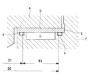
- the back pressure chamber adjacent to the back side of the end plate of the orbiting scroll when the back pressure chamber adjacent to the back side of the end plate of the orbiting scroll is formed and the orbiting scroll is pressed, the back pressure chamber surrounds the main shaft as viewed in the axial direction of the main shaft that rotationally drives the orbiting scroll. It becomes a ring.
- the smaller the inner diameter and the larger the outer diameter the larger the area (width) and the higher the pressing force of the orbiting scroll.
- the O located on the inner peripheral side of the back pressure chamber c is used.
- the diameter D1 of the ring-shaped inner peripheral seal ring d is reduced, and the diameter D2 of the outer peripheral seal ring e located on the outer peripheral side of the back pressure chamber c is increased, so that the gap between the inner peripheral seal ring d and the outer peripheral seal ring e is increased. It is necessary to widen the interval W1.
- the inner peripheral seal ring d and the outer peripheral seal ring e are each formed by forming a seal ring groove in the thrust surface g of the housing f, the gap between the inner peripheral seal ring d and the outer peripheral seal ring e is determined. There is a limit to widening the interval W1, and therefore the area of the back pressure chamber c cannot be effectively increased.
- the present invention has been made in view of such circumstances, and increases the pressing force of the orbiting scroll due to the back pressure by increasing the area of the back pressure chamber, thereby reducing the leakage of refrigerant gas from the chip clearance. It aims at providing the scroll compressor which can improve compression efficiency. A further object of the present invention is to reduce the starting torque and the noise during starting.
- the scroll compressor according to the present invention employs the following means.
- a scroll compressor supports a fixed scroll, a turning scroll that forms a compression chamber that compresses refrigerant gas facing the fixed scroll, and a thrust load of the turning scroll.
- a scroll compression mechanism having a thrust plate and a main shaft for driving the orbiting scroll, and a back pressure supply for supplying a part of the refrigerant gas compressed by the scroll compression mechanism as a back pressure to the back side of the thrust plate
- a housing that accommodates the scroll compression mechanism and the back pressure supply mechanism, and the back pressure supply mechanism has a back pressure formed on a thrust surface facing the back side of the thrust plate in the housing.
- An inner peripheral seal ring and an outer peripheral seal ring arranged to prevent leakage of the back pressure from the back pressure chamber, and the outer peripheral seal ring includes an inner peripheral surface of the housing, and It is provided so that it may be compressed between the outer peripheral surfaces of a thrust board.
- the outer peripheral seal ring disposed on the outer peripheral side of the back pressure chamber is provided so as to be compressed between the inner peripheral surface of the housing and the outer peripheral surface of the thrust plate. Therefore, it is not necessary to form a seal ring groove for the outer peripheral seal ring on the thrust surface of the housing as in the prior art. For this reason, the width of the back pressure chamber can be expanded to the outer peripheral side without being affected by the seal ring groove. Thereby, the area of the back pressure chamber can be increased to increase the pressing force of the orbiting scroll due to the back pressure, and the leakage of refrigerant gas can be reduced to increase the compression efficiency.
- the outer peripheral surface of the thrust plate is inclined so that an annular space having a right-angled triangle cross section is formed by the inner peripheral surface of the housing, the thrust surface, and the outer peripheral surface of the thrust plate.
- the outer peripheral seal ring may be pressed between three surfaces of the inner peripheral surface of the housing, the outer peripheral surface of the thrust plate, and the thrust surface.
- the triangular seal structure in which the outer peripheral seal ring is pressed between the three surfaces of the inner peripheral surface of the housing, the outer peripheral surface of the thrust plate, and the thrust surface is formed.
- an outer periphery seal ring can be arrange
- the outer peripheral seal ring is fitted into an outer peripheral groove formed on the outer peripheral surface of the thrust plate, and is compressed between the outer peripheral groove and the inner peripheral surface of the housing. It may be.
- the outer peripheral seal ring contacts only the outer peripheral surface (outer peripheral groove) of the thrust plate and the inner peripheral surface of the housing and does not contact the thrust surface, the width of the back pressure chamber formed on the thrust surface is reduced. It can be expanded to the maximum to increase the area.
- the size of the tip clearance between the fixed scroll and the orbiting scroll is such that the pressure in the compression chamber can leak before the back pressure is supplied to the orbiting scroll, You may set to the magnitude
- the tip clearance between the fixed scroll and the orbiting scroll is large at the start of the scroll compressor and there is a lot of leakage in the compression chamber, an effect that the start torque can be reduced is obtained.
- the pressure in the compression chamber gradually increases, and a part of this pressure is supplied as back pressure to the back surface of the thrust plate by the back pressure supply mechanism, and the orbiting scroll is pressed by this back pressure.
- the chip clearance is reduced, the compression chamber leakage is reduced, and the compression efficiency is normalized.
- the orbiting scroll receives back pressure at the time of start-up and moves to the fixed scroll at a stretch and does not collide with the fixed scroll, so that it is possible to effectively prevent an impact sound due to the collision, that is, noise at the time of start-up.
- the area of the back pressure chamber is increased to increase the pressing force of the orbiting scroll due to the back pressure, and the refrigerant gas leakage from the chip clearance is reduced to reduce the compression efficiency.
- it is possible to reduce the starting torque and the noise at the time of starting.
- FIG. 1 is a longitudinal sectional view showing an example of a scroll compressor according to the present invention.
- the scroll compressor 1 is incorporated in, for example, an air conditioner of an automobile and driven by engine power (not shown) to compress refrigerant gas and supply the compressed refrigerant gas to the refrigerant circuit of the air conditioner.
- the scroll compressor 1 includes a housing 2 having a configuration in which a rear housing 2b is fastened to a front housing 2a by bolts 3. Inside the housing 2, a scroll compression mechanism 5 and a back pressure supply mechanism 6 are accommodated. Has been.
- the scroll compression mechanism 5 includes a fixed scroll 8 fixed to the housing 2 (2b) with bolts 7 and the like, and a revolving scroll that forms a compression chamber 9 that opposes the fixed scroll 8 and compresses refrigerant gas. 10, a thrust plate 12 that supports a load in the thrust direction of the orbiting scroll 10, and a main shaft 14 that drives the orbiting scroll 10.
- the main shaft 14 is pivotally supported by the bearings 15 and 16 on the front housing 2a side, and its tip protrudes to the outside, and a drive pulley (not shown) is attached thereto.
- the fixed scroll 8 and the orbiting scroll 10 are integrally formed with spiral wraps 8b and 10b on one side of the disk-shaped end plates 8a and 10a, respectively.
- Each of the wraps 8b and 10b abuts the end plates 8a and 10a opposite to each other so as to be smoothly slidable, and is surrounded by the end plates 8a and 10a and the wraps 8b and 10b. Is formed.
- An eccentric pin 14a provided on the main shaft 14 is fitted to the inner periphery of the boss 10c of the orbiting scroll 10 via a bush 21 and a bearing 22.
- the orbiting scroll 10 rotates by a rotation prevention mechanism (not shown). Turn while being prevented. For this reason, the volume of the pair of compression chambers 9 formed between the fixed scroll 8 and the wraps 8b, 10b of the orbiting scroll 10 decreases from the outer peripheral side to the inner peripheral side, and the volume of the compression chambers 9 decreases.
- Refrigerant gas sucked from a suction port (not shown) provided in is sucked into the compression chamber 9 and compressed, and the refrigerant gas compressed to high pressure passes through the discharge valve 27 and the high pressure chamber 28 to the rear housing 2b. It discharges from the provided discharge outlet which is not illustrated.
- the back pressure supply mechanism 6 is a mechanism for supplying a part of the refrigerant gas compressed by the scroll compression mechanism 5 to the back side of the thrust plate 12 as a back pressure.
- the back pressure supply mechanism 6 includes an annular back pressure chamber 31 formed on the thrust surface 30, and a high pressure chamber 28 and a back pressure chamber 31 formed inside the front housing 2a.
- the back pressure supply passage 32 communicated, and the inner peripheral seal ring 33 and the outer peripheral seal ring 34 disposed on the inner peripheral side and the outer peripheral side of the back pressure chamber 31 are configured.
- the back pressure supply passage 32 is a passage for extracting a part of the refrigerant gas compressed in the compression chamber 9 and discharged to the high pressure chamber 28 and supplying the extracted refrigerant gas to the back pressure chamber 31. Further, the inner peripheral seal ring 33 and the outer peripheral seal ring 34 prevent back pressure leakage from the back pressure chamber 31, and airtightness is maintained.
- the inner peripheral seal ring 33 and the outer peripheral seal ring 34 are O-rings formed of, for example, an elastic material such as rubber, and the cross-sectional shape thereof is circular in an uncompressed state, but a cross-sectional shape other than circular is used. You can also.
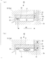
- FIGS. 2 (a) and 2 (b) are longitudinal sectional views of the back pressure supply mechanism 6 showing the first embodiment of the present invention by enlarging the II part of FIG.
- the thrust plate 12 is interposed between the thrust surface 30 of the front housing 2a and the orbiting scroll 10 (end plate 10a) so as to close the back pressure chamber 31.
- the inner peripheral seal ring 33 is fitted in a seal ring groove 35 formed on the thrust surface 30 and positioned on the inner peripheral side of the back pressure chamber 31 as in the conventional structure (see FIG. 5).
- the outer peripheral surface 12a of the thrust plate 12 is inclined at about 45 degrees, and the outer peripheral surface 12a and the thrust surface 30 and the inner peripheral surface 37 of the front housing 2a form an annular space having a right isosceles triangular cross section. Is formed.
- An outer peripheral seal ring 34 is attached inside the annular space. Therefore, the seal ring 34 is pressed between three surfaces of the inclined outer peripheral surface 12 a of the thrust plate 12, the thrust surface 30, and the inner peripheral surface 37.
- the outer peripheral seal ring 34 disposed on the outer peripheral side of the back pressure chamber 31 is provided to be compressed between the inner peripheral surface 37 of the front housing 2a and the outer peripheral surface 12a of the thrust plate 12. It has been. For this reason, it is not necessary to form a seal ring groove (groove of the outer peripheral seal ring e shown in FIG. 5) for fitting the outer peripheral seal ring 34 to the thrust surface 30 as in the prior art.
- the interval W2 between the inner peripheral seal ring 33 and the outer peripheral seal ring 34 can be expanded more than the conventional width W1 shown in FIG. 5, and the width of the back pressure chamber 31 formed therebetween can be increased. it can.
- the back pressure applied to the back pressure chamber 31 whose width has been expanded acts on the thrust plate 12 over the entire width W2 between the inner peripheral seal ring 33 and the outer peripheral seal ring 34. Therefore, it is possible to increase the compression efficiency of the scroll compressor 1 by increasing the pressing force of the orbiting scroll 10 due to the back pressure and reducing the leakage of the refrigerant gas.
- an annular space having a right isosceles triangle cross section is formed by the outer peripheral surface 12a, the inner peripheral surface 37 of the front housing 2a, and the thrust surface 30.
- the outer peripheral seal ring 34 can be disposed on the outermost peripheral portion of the thrust surface 30. Even in this respect, the width W2 and the area of the back pressure chamber 31 can be increased.
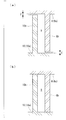
- FIGS. 3A and 3B are longitudinal sectional views of a back pressure supply mechanism 40 showing a second embodiment of the present invention. Since this back pressure supply mechanism 40 is the same as the back pressure supply mechanism 6 shown in the first embodiment except for the configuration of the outer peripheral seal ring 34 that maintains the airtightness of the back pressure chamber 31, the same configuration. Parts are denoted by the same reference numerals and description thereof is omitted.
- the outer peripheral surface 12b of the thrust plate 12 is a cylindrical surface parallel to the inner peripheral surface 37 of the front housing 2a, and the outer peripheral seal ring 34 is an outer periphery formed on the outer peripheral surface 12b of the thrust plate 12. It is fitted in the groove 41 and is mounted so as to be compressed between the outer peripheral groove 41 and the inner peripheral surface 37 of the front housing 2a. Therefore, the outer peripheral seal ring 34 has a structure that does not contact the thrust plate 12.
- the outer peripheral seal ring 34 contacts only the outer peripheral surface 12b (outer peripheral groove 41) of the thrust plate 12 and the inner peripheral surface 37 of the front housing 2a, and does not contact the thrust surface 30. .
- the interval W3 between the inner peripheral seal ring 33 and the outer peripheral portion (that is, the inner peripheral surface 37) of the outer peripheral seal ring 34 is larger than the interval W2 in the first embodiment (see FIG. 2).
- the width of the back pressure chamber 31 formed in the above can be made larger than in the case of the first embodiment.
- the back pressure applied to the back pressure chamber 31 having an increased width acts on the thrust plate 12 over the entire width W3 between the inner peripheral seal ring 33 and the outer peripheral portion (inner peripheral surface 37) of the outer peripheral seal ring 34. . Therefore, the pressing force of the orbiting scroll 10 due to the back pressure can be further increased to reduce the leakage of the refrigerant gas, and the compression efficiency of the scroll compressor 1 can be further improved.
- FIGS. 4A and 4B are partial longitudinal sectional views of a turning scroll and a fixed scroll showing a third embodiment of the present invention. This embodiment is preferably implemented in combination with the configuration of the first embodiment and the second embodiment.
- the tip of the wrap 8b of the fixed scroll 8 and the end plate 10a of the orbiting scroll 10 are separated.
- a predetermined tip clearance C is generated between the end of the orbiting scroll 10 and the end plate 8 a of the fixed scroll 8.
- the size of the tip clearance C is set to such a size that the pressure in the compression chamber 9 can leak, specifically, about 0.6 mm to 0.8 mm.
- the orbiting scroll 10 is lifted by the back pressure, so that the tip clearance C is eliminated and the pressure in the compression chamber 9 does not leak. It is like that.
- the tip clearance C between the fixed scroll 8 and the orbiting scroll 10 is large and there is a lot of leakage from the compression chamber 9, so that the starting torque can be reduced. It is done.
- the pressure in the compression chamber 9 gradually increases, and a part of this pressure is transferred to the back surface (back pressure) of the thrust plate 12 by the back pressure supply mechanisms 6 and 40 shown in FIGS.
- the back pressure is supplied to the chamber 31), and the orbiting scroll 10 is pressed by this back pressure, the tip clearance C is narrowed, the leakage of the compression chamber 9 is reduced, and the compression efficiency is normalized.
- the orbiting scroll 10 receives back pressure at the time of activation and moves to the fixed scroll 8 at a stroke and does not collide with the fixed scroll 8, and an impact sound due to the collision, that is, activation noise can be effectively prevented.
- the area of the back pressure chamber 31 is increased to increase the pressing force of the orbiting scroll 10 due to the back pressure, and the refrigerant gas leaks from the chip clearance. It is possible to increase the compression efficiency and reduce the starting torque and the noise at the time of starting.
- the scroll compressor 1 described in the above embodiment is used for an air conditioner of an automobile, but is not limited to an automobile, and the scroll compressor used for an air conditioner of a building such as a house, a building, or a warehouse.
- the present invention can also be applied to.
- scroll compressor 1 of the above embodiment is driven by external power such as an automobile engine
- present invention may be applied to an electric scroll compressor integrally provided with an electric motor.
Landscapes
- Engineering & Computer Science (AREA)
- Mechanical Engineering (AREA)
- General Engineering & Computer Science (AREA)
- Rotary Pumps (AREA)
- Applications Or Details Of Rotary Compressors (AREA)
Priority Applications (3)
| Application Number | Priority Date | Filing Date | Title |
|---|---|---|---|
| CN201580040958.6A CN107076143B (zh) | 2014-09-17 | 2015-07-28 | 涡旋压缩机 |
| US15/323,632 US10487831B2 (en) | 2014-09-17 | 2015-07-28 | Scroll compressor |
| DE112015004225.3T DE112015004225T5 (de) | 2014-09-17 | 2015-07-28 | Scroll- bzw. schneckenkompressor |
Applications Claiming Priority (2)
| Application Number | Priority Date | Filing Date | Title |
|---|---|---|---|
| JP2014-189061 | 2014-09-17 | ||
| JP2014189061A JP6548880B2 (ja) | 2014-09-17 | 2014-09-17 | スクロール圧縮機 |
Publications (1)
| Publication Number | Publication Date |
|---|---|
| WO2016042916A1 true WO2016042916A1 (ja) | 2016-03-24 |
Family
ID=55532960
Family Applications (1)
| Application Number | Title | Priority Date | Filing Date |
|---|---|---|---|
| PCT/JP2015/071299 Ceased WO2016042916A1 (ja) | 2014-09-17 | 2015-07-28 | スクロール圧縮機 |
Country Status (5)
| Country | Link |
|---|---|
| US (1) | US10487831B2 (enExample) |
| JP (1) | JP6548880B2 (enExample) |
| CN (1) | CN107076143B (enExample) |
| DE (1) | DE112015004225T5 (enExample) |
| WO (1) | WO2016042916A1 (enExample) |
Cited By (1)
| Publication number | Priority date | Publication date | Assignee | Title |
|---|---|---|---|---|
| JP2018150932A (ja) * | 2017-03-10 | 2018-09-27 | オーエーテー ゲゼルシャフト ミット ベシュレンクテル ハフツング | スパイラル原理による容積移送式機械、容積移送式機械を駆動するための方法、容積移送式スパイラル、車両空調設備及び車両 |
Families Citing this family (21)
| Publication number | Priority date | Publication date | Assignee | Title |
|---|---|---|---|---|
| CN109311032B (zh) | 2016-05-23 | 2021-04-16 | 东京滤器株式会社 | 分离盘层叠体 |
| US12065934B2 (en) | 2017-06-16 | 2024-08-20 | Trane International Inc. | Aerostatic thrust bearing and method of aerostatically supporting a thrust load in a scroll compressor |
| US11415135B2 (en) * | 2017-06-16 | 2022-08-16 | Trane International Inc. | Aerostatic thrust bearing and method of aerostatically supporting a thrust load in a scroll compressor |
| KR101970529B1 (ko) * | 2018-01-04 | 2019-04-19 | 엘지전자 주식회사 | 전동식 압축기 |
| KR102191123B1 (ko) * | 2019-01-18 | 2020-12-16 | 엘지전자 주식회사 | 전동식 압축기 |
| CN110308263B (zh) * | 2019-07-18 | 2024-01-26 | 天水红山试验机有限公司 | 一种粗粒土压缩试验压力室 |
| WO2021125200A1 (ja) | 2019-12-17 | 2021-06-24 | イーグル工業株式会社 | 摺動部品 |
| CN114787540A (zh) | 2019-12-17 | 2022-07-22 | 伊格尔工业股份有限公司 | 滑动部件 |
| EP4080091A4 (en) | 2019-12-17 | 2023-12-13 | Eagle Industry Co., Ltd. | SLIDING COMPONENT |
| US12196320B2 (en) | 2020-03-31 | 2025-01-14 | Eagle Industry Co., Ltd. | Sliding component |
| WO2021230081A1 (ja) | 2020-05-11 | 2021-11-18 | イーグル工業株式会社 | 摺動部品 |
| EP4177485A4 (en) | 2020-07-06 | 2024-07-24 | Eagle Industry Co., Ltd. | SLIDING ELEMENT |
| EP4177500A4 (en) | 2020-07-06 | 2024-08-14 | Eagle Industry Co., Ltd. | Sliding component |
| JP7528219B2 (ja) * | 2020-07-06 | 2024-08-05 | イーグル工業株式会社 | 摺動部品 |
| EP4177487A4 (en) | 2020-07-06 | 2024-07-24 | Eagle Industry Co., Ltd. | SLIDING COMPONENT |
| EP4177501A4 (en) | 2020-07-06 | 2024-08-14 | Eagle Industry Co., Ltd. | SLIDING COMPONENT |
| KR102877441B1 (ko) | 2020-07-06 | 2025-10-29 | 이구루코교 가부시기가이샤 | 회전 기계 |
| JP7595433B2 (ja) * | 2020-09-25 | 2024-12-06 | 三菱重工サーマルシステムズ株式会社 | スクロール圧縮機 |
| CN112610479B (zh) * | 2020-11-23 | 2022-09-09 | 珠海格力节能环保制冷技术研究中心有限公司 | 一种涡旋压缩机及空调 |
| CN116263158B (zh) * | 2021-12-13 | 2025-10-10 | 苏州英华特涡旋技术股份有限公司 | 动盘浮动装置及包括该动盘浮动装置的压缩机 |
| CN115013307A (zh) * | 2022-05-20 | 2022-09-06 | 重庆超力高科技股份有限公司 | 压缩机背压结构和涡旋压缩机 |
Citations (3)
| Publication number | Priority date | Publication date | Assignee | Title |
|---|---|---|---|---|
| JPH029973A (ja) * | 1988-06-28 | 1990-01-12 | Daikin Ind Ltd | スクロール型流体装置 |
| JP2006322421A (ja) * | 2005-05-20 | 2006-11-30 | Fujitsu General Ltd | スクロール圧縮機 |
| WO2010064426A1 (ja) * | 2008-12-02 | 2010-06-10 | サンデン株式会社 | スクロール型流体機械 |
Family Cites Families (12)
| Publication number | Priority date | Publication date | Assignee | Title |
|---|---|---|---|---|
| US4993928A (en) * | 1989-10-10 | 1991-02-19 | Carrier Corporation | Scroll compressor with dual pocket axial compliance |
| JP2865904B2 (ja) | 1991-06-07 | 1999-03-08 | 三菱重工業株式会社 | スクロール型流体機械 |
| JP2923088B2 (ja) | 1991-06-07 | 1999-07-26 | 三菱重工業株式会社 | スクロール型流体機械 |
| US5591014A (en) * | 1993-11-29 | 1997-01-07 | Copeland Corporation | Scroll machine with reverse rotation protection |
| JP3156520B2 (ja) * | 1994-09-20 | 2001-04-16 | 株式会社日立製作所 | スクロール流体機械 |
| JP3438361B2 (ja) * | 1994-12-09 | 2003-08-18 | ダイキン工業株式会社 | スクロール形圧縮機 |
| JP3893487B2 (ja) * | 1997-10-01 | 2007-03-14 | 三菱電機株式会社 | スクロール圧縮機 |
| US6695599B2 (en) * | 2001-06-29 | 2004-02-24 | Nippon Soken, Inc. | Scroll compressor |
| KR101101593B1 (ko) * | 2003-07-24 | 2012-01-02 | 파나소닉 주식회사 | 스크롤 압축기 |
| JP2009047040A (ja) * | 2007-08-17 | 2009-03-05 | Mitsubishi Heavy Ind Ltd | スクロール型流体機械 |
| JP5384017B2 (ja) * | 2008-03-27 | 2014-01-08 | 三洋電機株式会社 | スクロール圧縮機 |
| JP5433604B2 (ja) * | 2011-02-25 | 2014-03-05 | 日立アプライアンス株式会社 | スクロール圧縮機 |
-
2014
- 2014-09-17 JP JP2014189061A patent/JP6548880B2/ja active Active
-
2015
- 2015-07-28 WO PCT/JP2015/071299 patent/WO2016042916A1/ja not_active Ceased
- 2015-07-28 CN CN201580040958.6A patent/CN107076143B/zh active Active
- 2015-07-28 DE DE112015004225.3T patent/DE112015004225T5/de not_active Withdrawn
- 2015-07-28 US US15/323,632 patent/US10487831B2/en active Active
Patent Citations (3)
| Publication number | Priority date | Publication date | Assignee | Title |
|---|---|---|---|---|
| JPH029973A (ja) * | 1988-06-28 | 1990-01-12 | Daikin Ind Ltd | スクロール型流体装置 |
| JP2006322421A (ja) * | 2005-05-20 | 2006-11-30 | Fujitsu General Ltd | スクロール圧縮機 |
| WO2010064426A1 (ja) * | 2008-12-02 | 2010-06-10 | サンデン株式会社 | スクロール型流体機械 |
Cited By (1)
| Publication number | Priority date | Publication date | Assignee | Title |
|---|---|---|---|---|
| JP2018150932A (ja) * | 2017-03-10 | 2018-09-27 | オーエーテー ゲゼルシャフト ミット ベシュレンクテル ハフツング | スパイラル原理による容積移送式機械、容積移送式機械を駆動するための方法、容積移送式スパイラル、車両空調設備及び車両 |
Also Published As
| Publication number | Publication date |
|---|---|
| CN107076143A (zh) | 2017-08-18 |
| US20170146014A1 (en) | 2017-05-25 |
| JP6548880B2 (ja) | 2019-07-24 |
| DE112015004225T5 (de) | 2017-06-29 |
| CN107076143B (zh) | 2019-10-08 |
| US10487831B2 (en) | 2019-11-26 |
| JP2016061208A (ja) | 2016-04-25 |
Similar Documents
| Publication | Publication Date | Title |
|---|---|---|
| WO2016042916A1 (ja) | スクロール圧縮機 | |
| EP2803860B1 (en) | Scroll compressor | |
| US20130121866A1 (en) | Scroll compressor | |
| JP4142418B2 (ja) | スクロール式流体機械 | |
| US7611344B2 (en) | Sealing tabs on orbiting scroll | |
| US9523361B2 (en) | Scroll compressor having back pressure chamber that operatively contains a discharge pressure and an intermediate pressure during different periods of time within a single compression cycle | |
| US20130121864A1 (en) | Scroll compressor | |
| JP2006183527A (ja) | 流体機械 | |
| CN113677893B (zh) | 涡旋式压缩机及包括该涡旋式压缩机的制冷装置 | |
| CN111156166B (zh) | 涡旋式真空泵 | |
| CN103261695B (zh) | 具有分体式绕动涡盘的涡旋式压缩机 | |
| CN110206728B (zh) | 一种涡旋压缩机和空调器 | |
| JP2010156249A (ja) | スクロール圧縮機 | |
| CN216767751U (zh) | 涡旋式压缩机 | |
| CN100424353C (zh) | 涡旋式压缩机的防止磨损的装置 | |
| JP2005163745A (ja) | スクロール圧縮機 | |
| US7686599B2 (en) | Scroll compressor with device to limit orbit radius | |
| KR101727498B1 (ko) | 분리식 선회스크롤을 갖는 스크롤 압축기 | |
| CN215170749U (zh) | 涡旋式压缩机 | |
| WO2019021712A1 (ja) | スクロール型流体機械 | |
| JP2007239630A (ja) | スクロール圧縮機 | |
| KR100524789B1 (ko) | 스크롤 압축기의 축방향 지지 장치 | |
| JP2001173580A (ja) | スクロール型流体圧縮装置 | |
| JP2003314474A (ja) | スクロール式流体機械 | |
| JP2005048685A (ja) | スクロール圧縮機 |
Legal Events
| Date | Code | Title | Description |
|---|---|---|---|
| 121 | Ep: the epo has been informed by wipo that ep was designated in this application |
Ref document number: 15841761 Country of ref document: EP Kind code of ref document: A1 |
|
| WWE | Wipo information: entry into national phase |
Ref document number: 15323632 Country of ref document: US |
|
| WWE | Wipo information: entry into national phase |
Ref document number: 112015004225 Country of ref document: DE |
|
| 122 | Ep: pct application non-entry in european phase |
Ref document number: 15841761 Country of ref document: EP Kind code of ref document: A1 |