WO2016042642A1 - 測距光生成装置 - Google Patents
測距光生成装置 Download PDFInfo
- Publication number
- WO2016042642A1 WO2016042642A1 PCT/JP2014/074718 JP2014074718W WO2016042642A1 WO 2016042642 A1 WO2016042642 A1 WO 2016042642A1 JP 2014074718 W JP2014074718 W JP 2014074718W WO 2016042642 A1 WO2016042642 A1 WO 2016042642A1
- Authority
- WO
- WIPO (PCT)
- Prior art keywords
- distance measuring
- light
- distance
- optical element
- measuring light
- Prior art date
- Legal status (The legal status is an assumption and is not a legal conclusion. Google has not performed a legal analysis and makes no representation as to the accuracy of the status listed.)
- Ceased
Links
Images








Classifications
-
- G—PHYSICS
- G01—MEASURING; TESTING
- G01C—MEASURING DISTANCES, LEVELS OR BEARINGS; SURVEYING; NAVIGATION; GYROSCOPIC INSTRUMENTS; PHOTOGRAMMETRY OR VIDEOGRAMMETRY
- G01C3/00—Measuring distances in line of sight; Optical rangefinders
- G01C3/02—Details
- G01C3/06—Use of electric means to obtain final indication
Definitions
- the present invention relates to a ranging light generation device used for ranging of an imaging device.
- An imaging device that irradiates a target with uniform light and images a predetermined range of the target is widely used for authentication devices and the like.
- an authentication device for example, with the development of biometrics technology in recent years, the features of a living body that is a part that can distinguish individuals of the human body, for example, images of fingerprints of limbs, retinas of eyes, faces, blood vessels, etc.
- Various devices for recognizing features of a living body and performing personal authentication have been provided.
- the imaging device emits light with uniform light intensity in an imaging range (distance and area) where an object (part of a human body in biometric authentication) is present, and reflected light from the imaging range. Is converted into an electrical signal by the sensor, and a captured image signal is output.
- Patent Document 1 An imaging apparatus has been proposed in which the sensor distance measuring function for measuring the distance to the object is miniaturized.
- the target is tilted, a part of the target that is out of focus will come out and the resolution will be reduced, or the enlargement rate of the target will not be constant, leading to deterioration in authentication accuracy. It is required to measure the inclination of the object with higher accuracy. On the contrary, if the inclination of the object can be accurately grasped, the accuracy of the posture can be corrected at the time of collation with the registered data, so that the authentication accuracy is improved. For this purpose, it is necessary to increase the number of ranging light beams (beams) irradiated to the object. However, if the number of light emitting elements (LEDs) for distance measuring light is increased in order to increase the number of distance measuring light, the imaging apparatus is increased in size or power consumption is increased.
- LEDs light emitting elements
- an object of the present invention is to provide a distance measuring light generation device that generates a plurality of distance measuring lights from a light emitting element.
- a distance measuring light is provided in an imaging device that captures an object and generates distance measuring light for distance measurement on the object to be photographed.
- the optical element is composed of N convex lenses, and the optical axis of each convex lens is It is provided so as to be at a position displaced by a predetermined distance from the center of the optical element.
- a distance measuring light generating device that generates a plurality of distance measuring lights from a light emitting element.
- FIG. 1 It is a block diagram of the imaging device in which the ranging light generation device of the present invention is mounted. It is a figure which shows the example in which an imaging device is used as a palm vein sensor. It is a figure for demonstrating the structural example of an imaging device. It is the top view which looked at the imaging board from the upper part (object). It is the figure which looked at the ranging light emitted from each LED for ranging from the object side. It is a figure which shows the ranging image by which the target object irradiated with ranging light was image
- FIG. 1 is a block diagram of an image pickup apparatus 1 on which the distance measuring light generation apparatus of the present invention is mounted.
- the imaging device 1 is provided in a biometric authentication device, for example.
- a biometric authentication device is a device that images a fingerprint of a limb, a retina of an eye, a face, a blood vessel, and the like, recognizes characteristics of the biometric, and performs personal authentication.
- the imaging device 1 is provided in a biometric authentication device and outputs image data of a photographed object to an authentication unit of the biometric authentication device.
- the imaging device 1 emits light with uniform light intensity to a part of a human body, for example, a finger or palm, receives the reflected light with an imaging device, and outputs image data. In addition, the imaging device 1 calculates the distance and orientation to the object and outputs the information so that an appropriate image is captured.
- the imaging apparatus 1 includes a photographing lens unit 10, an imaging element 12, an illumination LED 16, a ranging LED 30, a control unit 100, an LED driving unit 112, an LED driving unit 114, an imaging processing unit 116, an image processing unit 118, and the like.
- the photographing lens unit 10 is for forming an optical image of an object on the image sensor 12.
- the image sensor 12 photoelectrically converts an imaged object and outputs an image signal, and is composed of, for example, a CCD or a CMOS.
- the imaging processing unit 116 amplifies the image signal output from the imaging element 12 and performs AD conversion to output image data.
- the image processing unit 118 performs interpolation processing, edge enhancement processing, and the like on the image data, and converts the image data into binary data, for example.
- the lighting LED 16 illuminates an object such as a palm during photographing.
- the illumination LEDs 16 are, for example, LEDs that emit infrared light, and a plurality of LEDs are provided.
- the LED driving unit 112 is an LED driver that drives the illumination LED 16.
- the distance measuring LED 30 is a light emitting element that emits distance measuring light for detecting whether the object is in an appropriate distance and in a correct posture before photographing the object.
- the LED driving unit 114 is an LED driver that drives the ranging LED 30.
- the control unit 100 is a control unit that comprehensively controls the entire imaging apparatus 1.
- the control unit 100 includes a CPU and a control program, and executes each process using software by the CPU that has read the control program.
- the control unit 100 includes a distance calculation unit 102 and a posture determination unit 104 as functional units as processing executed by the CPU. This is because the distance of the object and the posture of the object need to be set within a certain range in order to capture the authentication image as described above.
- the distance calculation unit 102 calculates the distance from the imaging device 1 to the object based on the image data in which the distance measurement light from the distance measurement LED 30 is reflected on the object.
- the posture discrimination unit 104 discriminates the posture of the object from the positions of the plurality of taken ranging light based on the image data in which the ranging light is captured. The description of distance calculation and posture determination will be described later.
- FIG. 2 is a diagram illustrating an example in which the imaging device 1 is used as a palm vein sensor.
- infrared light is irradiated as illumination light K from the illumination LED 16 of the imaging apparatus 1 to the object 300 (palm) held over the imaging apparatus 1, and image data of the palm is captured by the imaging element 12.
- the photographed palm image data is subjected to personal authentication by detecting the characteristics of the palm by the authentication device and comparing it with registered data or the like.
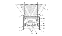
- FIG. 3 is a view for explaining an example of the structure of the imaging apparatus 1 and is a perspective view of the imaging apparatus 1 as viewed from the side.
- An imaging substrate 14 is horizontally disposed inside the imaging apparatus 1.
- the imaging device 12, the illumination LED 16, the ranging LED 30, and the like are mounted.
- the taking lens unit 10 is disposed on the image sensor 12.
- the LED 16 for illumination is arrange
- a ring light guide 20 that guides the illumination light K emitted from each illumination LED 16 to the target portion is disposed above the illumination LED 16.
- the ring light guide 20 is made of, for example, a resin, guides the light of each LED 16 for illumination upward, and uniformly irradiates the object 300 with the illumination light K.
- an optical element 50 that generates a plurality of distance measuring lights L from the light emitted from the distance measuring LED 30 is disposed above the distance measuring LED 30. Details of the optical element 50 will be described later.
- An aperture 80 is attached between the ranging LED 30 and the optical element 50. The aperture 80 shields the diffusion of light in other directions so that the light of the distance measuring LED 30 is directed toward the object.
- a processing substrate 15 is provided below the imaging substrate 14.
- the processing board 15 is provided with a connector for connecting to the LED driving unit 112, the LED driving unit 114, the imaging processing unit 116, and the control unit 100.
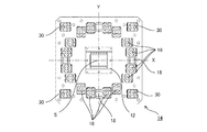
- FIG. 4 is a plan view of the imaging substrate 14 as viewed from above (the object 300).
- An imaging element 12 is provided in the center of the imaging substrate 14.
- a plurality of illumination LEDs 16, light receiving elements 18, and ranging LEDs 30 are mounted around the image sensor 12. With reference to the center S of the imaging surface of the imaging device 12, the XY axes are defined as shown. A direction passing through the center S and orthogonal to the paper surface is taken as the Z axis.
- the illumination LED 16 is arranged around the center S.
- a diffusion plate (not shown) or a polarizing plate (not shown) may be provided above the lighting LED 16.
- the diffusion plate diffuses the directional light emission distribution of the lighting LED 16 to some extent.
- the polarizing plate converts natural light of the illumination LED 16 into linearly polarized light.
- the ring light guide 20 is provided above the polarizing plate.
- the light receiving element 18 receives reflected light from the object due to light emission of the illumination LED 16 and controls the light emission amount of the illumination LED 16 to be appropriate.
- the ranging LEDs 30 are arranged at the four corners of the imaging board 14.
- the four distance measuring LEDs 30 are arranged on the diagonal line of the imaging board 14 at 90 ° intervals at equal distances from the center S, and the distances between the distance measuring LEDs 30 are arranged on the diagonal line farthest from each other. Is done. That is, each distance measuring LED 30 is arranged so that the center of the distance measuring LED 30 is equidistant from the center S of the imaging surface.
- FIG. 5 is a diagram of the ranging light L emitted from each ranging LED 30 as viewed from the object 300 side.
- the LED driving unit 114 By driving the LED driving unit 114, distance measuring light is emitted from each distance measuring LED 30 to the object.
- the distance measuring LED 30 is a square chip LED, and the distance measuring light L emitted is substantially square.
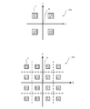
- C1 is a diagram showing distance measuring light L emitted from one distance measuring LED 30, and C2 is a diagram showing distance measuring light L emitted from four distance measuring LEDs 30.
- FIG. 6 is a diagram illustrating a distance measurement image in which the object 300 irradiated with the distance measurement light L is captured.
- FIG. 6 is a diagram illustrating that the position of the ranging light L on the screen changes depending on the distance of the object 300.
- the ranging image D1 is an image when the object 300 is close to the imaging device 1.
- the ranging image D2 is an image when the object 300 is at a distance far from the imaging device 1.
- four distance measurement spots Ls corresponding to the distance measurement light are respectively photographed.
- the length from the center S of the screen to the center of the distance measurement spot Ls is M, and M1 of the distance measurement image D1 near the object 300 is longer than M2 of the distance image D2 where the object 300 is far. This is because a subject at a close distance is photographed large and a subject at a distant distance is photographed small. Assuming that the distance measuring light L is parallel to the optical axis and the distance from the image sensor 12 to the distance measuring spot Ls of the object 300 is a distance H, the distance H is inversely proportional to M.
- the distance calculation unit 102 calculates a length M from the center S of the screen to the distance measurement spot Ls in the distance measurement image.
- the distance calculation unit 102 calculates the distance H from the calculated length M on the screen with reference to a conversion table showing the relationship between the distance H and the length M or using a conversion formula.
- the distance calculation unit 102 calculates the distance H of each ranging spot Ls.
- FIG. 7 is a diagram illustrating an example in which the target object 300 is tilted over the imaging apparatus 1.
- FIG. 8 is a diagram showing a distance measurement image of the distance measurement spot Ls in a tilted state as shown in FIG.
- the distance H from the image sensor 12 to each distance measuring spot Ls of the object 300 changes depending on the location. That is, in the state where it is not tilted as shown in FIG. 6, since the distance from the image sensor 12 to the object 300 is equidistant, the length M from the center S to each distance measuring spot Ls on the screen is equal.
- the two distance measurement spots Ls on the left side of the screen are longer than the distance measurement spots Ls on the right side by a length M from the center S. It can be seen from the distance measurement image D3 that the object 300 is tilted in such a direction that the left side of the object 300 approaches the imaging device 1 and the right side moves away from the imaging device 1.
- the two distance measurement spots Ls on the upper side of the screen are longer in the length M from the center S than the two distance measurement spots Ls on the lower side. It can be seen from the distance measurement image D4 that the object 300 is tilted in such a direction that the upper side of the object 300 approaches the imaging device 1 and the lower side moves away from the imaging device 1.
- the posture determination unit 104 determines the inclination of the object 300 from the distance H of each distance measurement spot Ls calculated by the distance calculation unit 102. Prior to the authentication image shooting, the object 300 is irradiated with distance measuring light from the distance measuring LED 30. Distance calculation and posture determination are performed by the distance calculation unit 102 and the posture determination unit 104. Based on the calculated distance and posture, it is determined whether the distance and posture are within the allowable range. If the distance and posture are out of the allowable range, a warning or an instruction is issued to the user. After it is confirmed that the object 300 is in the allowable range, the authentication image is taken.
- FIG. 9 is a diagram modeling the target surface discriminated by the posture discriminating unit 104.
- FIG. 9A is a diagram showing a state in which the object 300 (palm) is irradiated with four distance measuring spots Ls (Ls1 to Ls4).
- FIG. 9B is a diagram illustrating an example of the surface (target object surface) of the target object 300 calculated from the distances H of the four distance measuring spots Ls.
- Squares indicated by broken lines are virtual planes 320 each having four illuminating LEDs 16 arranged on the imaging substrate 14 as vertices.
- the target object surface that is the object surface of the target object 300 is calculated by the deviation of the distance H between the distance measuring spots Ls4 (Ls1 to Ls4).
- the target object surface 310a is a case where there is no inclination of the target object 300 (palm).
- the distance H between the distance measuring spots Ls4 (Ls1 to Ls4) is equal to Ha.
- the distance calculation unit 102 calculates that the distance Ha of Ls3 has been extended by the distance ⁇ H due to the change in position of Ls3 in the distance measurement image D.
- the posture determination unit 104 generates a target object plane 310b as the shape of the tilted target object 300 from each distance measurement spot Ls4 (Ls1 to Ls4).
- the four-point information has a poor reproduction accuracy of the target object surface of the target object 300 and is insufficient to improve the recognition rate of the authentication image.
- FIG. 10 is a diagram showing the shape of a conventional optical element 150.
- the conventional optical element 150 has a flat entrance surface and a light exit surface formed in a convex lens shape, and condenses the light emitted from the distance measuring LED 30 and emits it as the distance measuring light L to the object 300.
- the direction from the distance measuring LED 30 toward the object 300 is taken as the Z axis.
- FIG. 11 is a ray diagram of the distance measuring light L by the conventional optical element 150.
- the shape of the optical element 50 of the present embodiment will be described with reference to FIGS.
- the number of divisions is not limited to four, and may be two, three, or five or more.
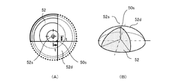
- FIG. 12 is a diagram showing the shape of the optical element 50 of the present embodiment.
- FIG. 12A is a top view of the optical element 50 as viewed from the object 300 side.
- FIG. 12B is a perspective view of the optical element 50 as viewed obliquely from above.
- FIG. 12C is a perspective view of the optical element 50 as viewed obliquely from below.
- the optical element 50 is configured by integral molding of transparent plastic, for example.
- the surface of the optical element 50 on which the emitted light from the ranging LED 30 is incident is referred to as an incident side (or incident surface), and the surface of the optical element 50 from which the emitted light is emitted is referred to as an emission side (or an emission surface).
- each convex lens 52 is gathered on the exit side of the optical element 50.
- the four convex lenses 52 have the same shape and are arranged around the optical element center 50 s that is the center of the optical element 50.
- the convex lens 52 is a partially convex lens obtained by cutting out (extracting) a part of the entire convex lens.
- the convex lens 52 has its optical axis 52 s shifted from the optical element center 50 s by t in the XY directions, and the surface shifted from the optical axis 52 s by t is the end surface of each convex lens 52.
- FIG. 13 is a diagram for explaining the shape of the convex lens 52 extracted from the entire original convex lens.
- FIG. 13A shows the relationship between the convex lens 52 in the second quadrant of FIG. 12A and the original convex lens 52d.
- the original convex lens 52d of the convex lens 52 is indicated by a broken line.
- the convex lens 52 has such a shape that the original convex lens 52d is cut out at an angle of 90 ° at a position shifted in the XY direction by a predetermined distance t vertically and horizontally from the optical axis 52s so as to include the optical axis 52s.
- FIG. 13B is a perspective view showing the relationship of the convex lens 52 with respect to the original convex lens 52d.
- each of the four cylindrical lenses 54 is provided corresponding to the four convex lenses 52.
- the convex lens 52 and the cylindrical lens 54 form one pair. It can be said that the optical element 50 is composed of four pairs.
- a cylindrical lens 54 is formed on the back side (incident side) of each convex lens 52.
- the cylindrical lens 54 is indicated by a broken line.
- the cylindrical lens 54 is provided on the incident side in such a direction that the cylindrical portion 54 a faces the ranging LED 30.
- the cylindrical lens 54 is arranged such that the axis 54b of the cylindrical lens 54 is at a 45 ° direction on the XY plane with respect to the corresponding convex lens 52. That is, the four cylindrical lenses 54 are arranged such that each axis 54b passes through the optical element center 50s and is radial from the optical element center 50s. Further, as shown in FIG. 15 to be described later, each cylindrical lens 54 is provided so that the axis 54b is inclined so as to approach the distance measuring LED 30 on the optical element center 50s side and away from the distance measuring LED 30 on the peripheral side. It is done.
- FIG. 14 is a view showing the relationship of the aperture 80 and the like with respect to the optical element 50, and is a view seen from the same direction as FIG. 12 (A).
- the outer shape of the aperture 80 is omitted.
- four circular openings 80a are formed at equal intervals of 90 °.
- each opening 80 a is disposed on the back surface (incident side) of each convex lens 52.
- the optical element 50 is arranged so that the optical element center 50 s coincides with the center T of the distance measuring LED 30.
- a circumferential direction Q and a radial direction R described below are directions shown in FIG.
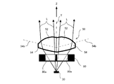
- FIG. 15 is a side view showing generation of a plurality of distance measuring lights L by the optical element 50. It is EE sectional drawing of FIG. An optical element 50 is provided above the distance measuring LED 30, and an aperture 80 is provided between the distance measuring LED 30 and the optical element 50.
- the light emitted from the ranging LED 30 is separated into four luminous fluxes by the four openings 80a of the aperture 80.
- Each separated light beam is incident on each cylindrical lens 54 of the optical element 50.
- the light beam incident on the cylindrical lens 54 is converged in the circumferential direction Q by the power of the cylindrical portion 54 a of the cylindrical lens 54. Since the cylindrical lens 54 does not have power in the radial direction R, the light beam incident on the cylindrical lens 54 is not converged in the radial direction R.
- the light beams emitted from the cylindrical lens 54 are converged in the radial direction R extending in the circumferential direction Q by the convex lens 52 and emitted to the object 300.
- the object 300 is irradiated with four distance measuring lights L respectively emitted from the four convex lenses 52 of the optical element 50.
- four distance measuring lights are generated by the aperture 80 and the optical element 50 from one emitted light of the distance measuring LED 30.
- FIG. 16 is a diagram showing imaging characteristics when the cylindrical lens 54 is not provided on the incident side of the optical element 50, that is, when the incident side is configured as a plane.
- FIG. 16A is a ray diagram on the XZ plane.
- a dispersion range of the ranging light L is indicated by G1. It can be seen that the dispersion in the circumferential direction Q is larger than that in the radial direction R.
- FIG. 17 is a diagram showing the imaging characteristics when the cylindrical lens 54 is provided on the incident side of the optical element 50 as described with reference to FIGS.
- FIG. 17A is a ray diagram on the XZ plane.
- G1 in FIG. 16 is indicated by a broken line.
- G2 is narrower in the circumferential direction Q than G1, and it can be seen that the dispersion in the circumferential direction Q is improved.
- each of the distance measuring lights L divided into four is low in image formation in the circumferential direction Q. Therefore, by providing a cylindrical lens 54 having power only in the circumferential direction Q on the incident side, the imaging characteristics are improved as shown in FIG.
- FIG. 18 is a diagram showing the light emitted from each distance measuring LED 30 and the distance measuring light L generated by the optical element 50 in comparison. It is the figure seen from the same direction as FIG. C3 in FIG. 18 is a diagram illustrating four emitted lights emitted from the four ranging LEDs 30. As shown at C4 in FIG. 18, each light emission is divided into four by the optical element 50 to become a total of 16 distance measuring lights L. Then, the 16 distance measuring lights L are applied to the object 300.
- FIG. 19 shows the distribution state (C5 to C7) of the distance measurement spots Ls formed on the object 300 by the distance measurement light L and the distance measurement images (D5 to D7) photographed correspondingly. It is a figure shown according to perspective.
- C5 is a diagram showing a distribution state of the distance measurement spots Ls on the object 300 at a short distance.
- a captured image corresponding to C5 is a distance measurement image D5.
- C6 is a diagram showing a distance measurement spot Ls on the object 300 at a medium distance.
- a captured image corresponding to C6 is a distance measurement image D6.
- C7 is a diagram illustrating a distance measuring spot Ls on the object 300 at a long distance. The captured image corresponding to C7 is a distance measurement image D7.
- the distance on the object 300 increases as the distance measurement spot Ls increases. Therefore, on the object 300, the size of the distance measurement spot Ls at the long distance C7 is larger than the distance measurement spot Ls at the short distance C5.
- the length M from the center S to the distance measurement spot Ls changes according to the distance H, and the length M decreases as the distance H increases.
- a change in length from the center S of the distance measurement spot Ls1 in the upper left is shown.
- the relationship is M5> M6> M7.
- FIG. 20 is a diagram showing the inclination of the target object plane calculated by the 16 distance measuring lights L.
- FIG. 20A is a diagram illustrating a state in which the object 300 is irradiated with 16 distance measuring lights L.
- FIG. The distance measuring spots Ls by the 16 distance measuring lights L are shown as distance measuring spots Ls1 to Ls16.
- FIG. 20B is a diagram illustrating the calculated target object surface 310b having an inclination.
- Each distance measuring spot Ls16 (Ls1 to Ls16) corresponds to each vertex of the target object surface 310b.
- a virtual plane 320 is shown below the target object plane 310b.
- FIG. 20C is a diagram showing the relationship between the target object surface 310b and the height H.
- FIG. From the distance measurement image D as shown in FIG. 19, the position of each distance measurement spot Ls on the screen is calculated from the center S of the screen, and the distance H of each distance measurement spot Ls is calculated accordingly.
- a target object surface 310b having an inclination is generated from the deviation of the distance H between the distance measuring spots Ls. Since the number of distance measuring lights is quadrupled, the shape of the target object surface can be reproduced with higher accuracy than in the case of four points in FIG. 9B.
- the division number N of the optical element 50 is not limited to 4, and may be 2 or 3, or 5 or more.
- the number of divisions is 3, three convex lenses 52 may be provided on the exit surface of the optical element 50 at intervals of 120 degrees.
- three cylindrical lenses 54 may be provided on the lower surface of the convex lens 52.
- Three openings 80a may be sufficient.
Landscapes
- Physics & Mathematics (AREA)
- Electromagnetism (AREA)
- Engineering & Computer Science (AREA)
- General Physics & Mathematics (AREA)
- Radar, Positioning & Navigation (AREA)
- Remote Sensing (AREA)
- Measurement Of Optical Distance (AREA)
- Studio Devices (AREA)
Abstract
発光素子から複数の測距光を生成する測距光生成装置を提供すること。対象物を撮影する撮像装置に設けられ、撮影される対象物に対して距離測定用の測距光を生成する測距光生成装置において、測距光を発光する発光素子と、発光素子の発光光からN個(N≧2)の測距光を分割生成する光学素子を備え、光学素子は、N個の凸レンズで構成されており、各凸レンズの光軸が光学素子の中心から所定距離ずれた位置になるよう設けられた。
Description
本発明は、撮像装置の測距に用いられる測距光生成装置に関する。
対象物に均一な光を照射し、対象物の所定範囲を撮像する撮像装置は、認証装置等に広く利用される。認証装置として、例えば、近年のバイオメトリックス技術の発展に伴い、人間の体の個人を区別できる部分である生体の特徴を、例えば、手足の指紋、目の網膜、顔面、血管など、撮像し、生体の特徴を認識して、個人認証する装置が種々提供されている。
特に、手のひらや指の血管、掌紋は、比較的大量の個人特徴データを得られるため、個人認証の信頼性に適している。又、血管(静脈)の模様は、胎児の時から生涯変わらず、万人不同と言われおり、個人認証に適している。生体認証等では、撮像装置によって、対象物(生体認証では、人間の体の一部)のある撮像範囲(距離及び面積)に光強度が均一となる光が発射され、その撮像範囲の反射光がセンサにより電気信号に変換され、撮像画像信号が出力される。
認証用の撮像装置では、鮮明な撮像画像が要求され、対象物が合焦距離に位置しているかを検出する必要がある。そこで、この対象物との距離を測定するセンサ距離測定機能を小型化した撮像装置が提案されている(特許文献1)。
対象物が傾いていると対象物の一部でピントの合わない部分が出て解像度が低下したり、あるいは、対象物の拡大率が一定でなくなったりして、認証精度の悪化につながるため、対象物の傾き等をより高精度に測定することが求められる。逆に対象物の傾きを正確に把握できれば、登録されたデータとの照合の際に、精度の高い姿勢補正が行えるため、認証精度が向上することになる。そのためには、対象物へ照射する測距光(ビーム)の数を増やすことが必要になる。しかし、測距光の数を増やすために、測距光用の発光素子(LED)の数を増加させると、撮像装置の大型化を招いたり、あるいは消費電力の増加にも繋がってしまう。
本願発明は、上記課題に鑑み、発光素子から複数の測距光を生成する測距光生成装置を提供することを目的とする。
上記目的を達成するために、対象物を撮影する撮像装置に設けられ、撮影される対象物に対して距離測定用の測距光を生成する測距光生成装置において、測距光を発光する発光素子と、発光素子の発光光からN個(N≧2)の測距光を分割生成する光学素子を備え、光学素子は、N個の凸レンズで構成されており、各凸レンズの光軸が光学素子の中心から所定距離ずれた位置になるよう設けられる。
本発明によれば、発光素子から複数の測距光を生成する測距光生成装置を提供することができる。
以下、図面に従って本発明の実施形態を説明する。図1は、本発明の測距光生成装置が搭載される撮像装置1のブロック図である。撮像装置1は、例えば、生体認証装置に備えられる。生体認証装置は、手足の指紋、目の網膜、顔面、血管などを、撮像し、生体の特徴を認識して、個人認証する装置である。撮像装置1は、生体認証装置に備えられ、撮影した対象物の画像データを生体認証装置の認証部に出力する。
撮像装置1は、人間の体の一部、例えば指や掌に、光強度が均一となる光を発射し、その反射光を撮像素子で受光し、画像データを出力する。また、撮像装置1は、適切な画像が撮影されるように、対象物までの距離や姿勢を算出して、その情報を出力する。
撮像装置1は、撮影レンズ部10、撮像素子12、照明用LED16、測距用LED30、制御部100、LED駆動部112、LED駆動部114、撮像処理部116、画像処理部118等を有する。
撮影レンズ部10は、対象物の光学像を撮像素子12に結像するためのものである。撮像素子12は、結像された対象物を光電変換して画像信号を出力するもので、例えば、CCDやCMOSで構成される。撮像処理部116は、撮像素子12から出力された画像信号を増幅してAD変換して画像データを出力する。画像処理部118は、画像データに対して、補間処理やエッジ強調処理等を行い、例えば、2値化データに変換する。
照明用LED16は、撮影時に掌等の対象物を照明する。照明用LED16は、例えば、赤外光を発光するLEDで、複数個設けられる。LED駆動部112は、照明用LED16を駆動するLEDドライバーである。
測距用LED30は、対象物の撮影に先立って、対象物が適正な距離でかつ正しい姿勢になっているかを検出するための測距光を発光する発光素子である。LED駆動部114は、測距用LED30を駆動するLEDドライバーである。
制御部100は、撮像装置1全体を統括的に制御する制御部である。制御部100は、CPUと制御プログラムを有し、制御プログラムを読込んだCPUによるソフトウェアにより各処理を実行する。制御部100は、CPUにより実行される処理として、距離算出部102及び姿勢判別部104を機能部として有する。前述のように、認証用画像の撮影のためには、対象物の距離や対象物の姿勢が一定の範囲内に設定されることが必要だからである。
距離算出部102は、対象物に測距用LED30からの測距光が写った画像データに基づき、撮像装置1から対象物までの距離を算出する。姿勢判別部104は、測距光が写った画像データに基づき、撮影された複数の測距光の位置から、対象物の姿勢を判別する。距離算出や姿勢判別の説明は、後述する。
図2は、撮像装置1が手のひら静脈センサとして使用される例を示す図である。撮像装置1の上にかざされた対象物300(手のひら)に、撮像装置1の照明用LED16から照明光Kとして、例えば赤外光が照射され、撮像素子12により手のひらの画像データが撮影される。撮影された手のひらの画像データは、認証装置によって、手のひらの特徴が検出され、登録データ等と比較され、個人認証が行われる。
図3は、撮像装置1の構造例を説明するための図で、撮像装置1を側面から見た透視図ある。撮像装置1内部に撮像基板14が水平に配置される。撮像基板14には、撮像素子12、照明用LED16、測距用LED30等が実装される。撮像素子12の上に撮影レンズ部10が配置される。
照明用LED16は撮像素子12の回りを取り囲むように複数周状に配置される。照明用LED16の上部に、各照明用LED16から発光される照明光Kを対象部までガイドするリング導光体20が配置される。リング導光体20は、例えば、樹脂で構成され、各照明用LED16の光を上方に導き、対象物300に照明光Kを均一に照射するものである。
また、測距用LED30の上部に、測距用LED30の発光光から複数の測距光Lを生成する光学素子50が配置される。光学素子50の詳細は、後述する。測距用LED30と光学素子50の間にはアパーチャー80が取り付けられる。アパーチャー80は、測距用LED30の光が、対象物方向に向かうように、他の方向への光の拡散を遮蔽するものである。
撮像基板14の下部に、処理基板15が設けられる。処理基板15には、LED駆動部112、LED駆動部114、撮像処理部116及び制御部100と接続されるためのコネクタ等が設けられる。
図4は、撮像基板14を上部(対象物300)から見た平面図である。撮像基板14の中央には、撮像素子12が設けられる。撮像素子12の周囲には、複数の照明用LED16、受光素子18及び測距用LED30が搭載される。撮像素子12の撮像面の中心Sを基準として、図示のようにXY軸を規定する。中心Sを通り、紙面に直交する方向をZ軸とする。照明用LED16は、中心Sを中心に配置される。
また、照明用LED16の上方には、拡散板(不図示)や偏光板(不図示)を設けてもよい。拡散板は、照明用LED16の指向性のある発光分布をある程度拡散するものである。偏光板は、照明用LED16の自然光を直線偏光に変換するものである。その場合、偏光板の上方に、リング導光体20が設けられる。
受光素子18は、照明用LED16の発光による対象物からの反射光を受光し、照明用LED16の発光量を適正になるよう制御するためのものである。
測距用LED30は、撮像基板14の四隅に配置される。この4つの測距用LED30は、中心Sから等距離の位置に90°間隔で、撮像基板14の対角線上に配置され、且つ各々測距用LED30の間隔は、最も距離の遠い対角線上に配置される。つまり、各測距用LED30は、その測距用LED30の中心が撮像面の中心Sから等距離になるように配置される。
<距離算出及び姿勢判別の原理>
このような撮像装置1における、距離算出部102及び姿勢判別部104により行なわれる処理を、図5~図9を参照して説明する。なお、本実施形態では測距光Lを16本に分割する例を説明するが、ここでは、説明を簡単にするため、測距光Lの数を4本として説明する。
このような撮像装置1における、距離算出部102及び姿勢判別部104により行なわれる処理を、図5~図9を参照して説明する。なお、本実施形態では測距光Lを16本に分割する例を説明するが、ここでは、説明を簡単にするため、測距光Lの数を4本として説明する。
図5は、各測距用LED30から発光される測距光Lを対象物300側から見た図ある。LED駆動部114の駆動により、各測距用LED30から測距光が対象物に発せられる。ここでは、測距用LED30を正方形チップLEDの場合とし、発光される測距光Lは、略正方形となる。C1は、1つの測距用LED30から発光される測距光Lを示す図で、C2は、4つの測距用LED30から発光される測距光Lを示す図である。
対象物300に4つの測距光Lが照射され、測距光Lが照射された対象物300の画像が、撮像素子12で撮影される。図6は、測距光Lが照射された対象物300が撮影された測距画像を示す図である。図6は、対象物300の遠近により、画面上での測距光Lの位置が変化することを示すための図である。
測距画像D1は、対象物300が撮像装置1から近い距離にある場合の画像である。測距画像D2は、対象物300が撮像装置1から遠い距離にある場合の画像である。測距画像D1、D2には、それぞれ測距光に対応する測距スポットLsが4点撮影される。
画面の中心Sから測距スポットLsの中心までの長さをMとし、対象物300が近い測距画像D1のM1は、対象物300が遠い測距画像D2のM2よりも、長くなる。近い距離にある被写体は大きく撮影され、遠い距離にある被写体は、小さく撮影されるからである。測距光Lが光軸に平行であるとして、撮像素子12から対象物300の測距スポットLsまでの距離を距離Hとすると、距離Hは、Mに反比例する。
距離算出部102は、測距画像で画面の中心Sから測距スポットLsまでの長さMを算出する。距離算出部102は、距離Hと長さMの関係を示した換算テーブルを参照し、あるいは換算式を用いて、算出した画面上の長さMから、距離Hを算出する。距離算出部102は、各測距スポットLsの距離Hを算出する。
図7は、撮像装置1に対して対象物300が傾いてかざされた例を示す図である。図8は、図7のような傾いた状態での測距スポットLsの測距画像を示す図である。対象物300が傾くことで、撮像素子12から対象物300の各測距スポットLsまでの距離Hが、場所によって変化する。つまり、図6のように傾いていない状態では、撮像素子12からから対象物300までが等距離にあるので、画面上で中心Sから各測距スポットLsまでの長さMは、等しくなる。
これに対して、対象物300が傾いた状態(図7)になると、撮像素子12から対象物300の各測距スポットLsまでの距離Hが異なるので、画面上で中心Sから各測距スポットLsまでの長さMも異なる。
例えば、測距画像D3では、画面の左側の2点の測距スポットLsが、右側の2点の測距スポットLsよりも、中心Sからの長さMが長い場合である。この測距画像D3により、対象物300の向かって左側が撮像装置1に接近し、右側が撮像装置1から遠ざかるような向きで、対象物300が傾いていることが分かる。
また、測距画像D4は、画面の上側の2点の測距スポットLsが、下側の2点の測距スポットLsよりも、中心Sからの長さMが長い場合である。測距画像D4により、対象物300の向かって上側が撮像装置1に接近し、下側が撮像装置1から遠ざかるような向きで、対象物300が傾いていることが分かる。
姿勢判別部104は、距離算出部102により算出された各測距スポットLsの距離Hから、対象物300の傾きを判別する。そして、認証画像撮影に先立ち、対象物300に対して測距用LED30から測距光が照射される。距離算出部102及び姿勢判別部104により、距離算出と姿勢判別がなされる。算出された距離と姿勢により、距離及び姿勢が許容範囲内であるかが判断され、範囲外である場合には、ユーザに対して警告や指示が発せられる。対象物300が許容範囲内の状態であることが確認されてから、認証画像の撮影が行われる。
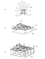
図9は、姿勢判別部104により判別された対象面をモデル化した図である。図9(A)は、対象物300(手のひら)に4点の測距スポットLs(Ls1~Ls4)が照射された状態を示す図である。
図9(B)は、4点の測距スポットLsの各距離Hから算出された対象物300の面(対象物体面)の例を示す図である。破線で示す正方形は、撮像基板14に配置された4か所の照明用LED16を各頂点とする仮想の平面320である。対象物300の物体面である対象物体面は、各測距スポットLs4点(Ls1~Ls4)の距離Hの偏差により、算出される。
対象物体面310aは、対象物300(手のひら)の傾きが無い場合である。各測距スポットLs4点(Ls1~Ls4)の距離Hは、Haで等しい。
対象物300(手のひら)が傾いて、Ls3がLs3bの位置に変化したとすると、測距画像D上で、Ls3は、中心Sに近づく。距離算出部102は、測距画像DでのLs3の位置変化により、Ls3の距離Haが距離ΔHだけ伸びたことを算出する。姿勢判別部104は、各測距スポットLs4点(Ls1~Ls4)から、傾いた対象物300の形状として、対象物体面310bを生成する。
<光学素子50の説明>
図9で示したように4点の情報では、対象物300の対象物体面の再現精度は粗く、認証画像の認識率を向上させるためには、不十分である。対象物300の物体面形状を精度よく検出するためには、測距光を増やす必要がある。そこで、測距用LED30の発光光から複数の測距スポットLsを生成することにより、測距用LED30の数を増やさずに、測距スポットLs数を増加させることができる光学素子についてを、以下に説明する。
図9で示したように4点の情報では、対象物300の対象物体面の再現精度は粗く、認証画像の認識率を向上させるためには、不十分である。対象物300の物体面形状を精度よく検出するためには、測距光を増やす必要がある。そこで、測距用LED30の発光光から複数の測距スポットLsを生成することにより、測距用LED30の数を増やさずに、測距スポットLs数を増加させることができる光学素子についてを、以下に説明する。
まず、対比例として、従来の測距用LED30の光学系を説明する。図10は、従来の光学素子150の形状を示す図である。従来の光学素子150は、入射面が平坦で出射面が凸レンズ状に形成され、測距用LED30からの発光光を集光して測距光Lとして、対象物300に出射するものである。測距用LED30から対象物300へ向かう方向をZ軸とする。
測距用LED30の発光光は、アパーチャー180で絞られる。アパーチャー180で一定範囲に絞られた測距光Lは、凸レンズ状の光学素子150により、略平行な光束に集光され、対象物300に照射される。図11は、従来の光学素子150による測距光Lの光線図である。
次に、本実施形態の光学素子50の形状を図12~図14を用いて説明する。なお、以下では、測距用LED30の発光光を4分割する場合の光学素子50の形状を説明するが、分割数は4に限るものではなく、2、3あるいは、5以上でも可能である。
図12は本実施形態の光学素子50の形状を示す図である。図12(A)は、光学素子50を、対象物300側から見た上面図である。図12(B)は、光学素子50を斜め上から見た斜視図である。図12(C)は、光学素子50を斜め下から見た斜視図である。
光学素子50は、例えば、透明プラスチックの一体成型で構成される。測距用LED30からの発光光が入射する光学素子50の面を、入射側(あるいは入射面)、発光光が出射する光学素子50の面を、出射側(あるいは出射面)と呼ぶ。
図12(A)、(B)に示すように、光学素子50の出射側には、4つの凸レンズ52が集合した形状で設けられる。4つの凸レンズ52は、同一形状で、光学素子50の中心である光学素子中心50sを中心として、配置される。
凸レンズ52は、凸レンズ全体からその一部を切り出した(抽出した)ような部分凸レンズである。凸レンズ52は、その光軸52sが、光学素子中心50sから、XY方向にそれぞれtだけずれた状態になっていて、光軸52sからtだけずれた面が各凸レンズ52の端面となる。
図13は、元の凸レンズ全体から抽出した凸レンズ52形状を説明するための図である。図13(A)は、図12(A)の第2象限の凸レンズ52と、元の凸レンズ52dの関係を示す図である。凸レンズ52の元の凸レンズ52dを破線で示す。凸レンズ52は、元の凸レンズ52dを、光軸52sを含むように、光軸52sから縦横に所定距離tだけXY方向にずらした位置で、90°の角度で切り出したような形状である。図13(B)は、元の凸レンズ52dに対する凸レンズ52の関係を示す斜視図である。
また、図12(C)に示すように、光学素子50の入射側には、4つのシリンドリカルレンズ54が設けられる。4つの各シリンドリカルレンズ54は、4つの凸レンズ52と対応して設けられる。凸レンズ52とシリンドリカルレンズ54が1つのペアとなる。光学素子50は4つのペアから構成されるとも言える。
各凸レンズ52の裏面側(入射側)に、シリンドリカルレンズ54が形成される。図12(A)では、シリンドリカルレンズ54を破線で示す。図12(C)に示すように、シリンドリカルレンズ54は、円筒部54aが、測距用LED30に対向するような向きで、入射側に設けられる。
また、シリンドリカルレンズ54は、シリンドリカルレンズ54の軸線54bが、対応する凸レンズ52に対して、XY平面上で45°の方向に配置される。つまり、4つのシリンドリカルレンズ54は、各軸線54bが光学素子中心50sを通り、光学素子中心50sから放射状になるよう配置される。また、後述する図15で示すように、各シリンドリカルレンズ54は、光学素子中心50s側で測距用LED30に接近し、周辺側で測距用LED30から遠ざかるように、軸線54bが傾くように設けられる。
図14は、光学素子50に対するアパーチャー80等の関係を示す図で、図12(A)と同様な方向から見た図である。アパーチャー80の外形は省略する。アパーチャー80には、90°等間隔で、円形の開口80a(破線)が4つ形成される。図14に示すように、各凸レンズ52の裏面(入射側)に、それぞれの開口80aが配置される。また、光学素子50は、光学素子中心50sが、測距用LED30の中心Tに一致するように配置される。なお、以下で説明する円周方向Q及び半径方向Rは、中心Tを基準にした図14に示す方向とする。
図15は、光学素子50による測距光Lの複数生成を示す側面図である。図14のEE断面図である。測距用LED30の上部に光学素子50が設けられ、測距用LED30と光学素子50の間にアパーチャー80が設けられる。
測距用LED30から出射された光は、アパーチャー80の4つの開口80aにより4つの光束に分離される。分離された各光束が、光学素子50の各シリンドリカルレンズ54に入射する。シリンドリカルレンズ54に入射した光束は、シリンドリカルレンズ54の円筒部54aのパワーにより円周方向Qに収束される。なお、シリンドリカルレンズ54は半径方向Rへのパワーは持たないので、シリンドリカルレンズ54に入射した光束は、半径方向Rへは収束されない。
そして、シリンドリカルレンズ54から出射された光束は、凸レンズ52で、円周方向Q及ぶ半径方向Rにそれぞれ収束されて、対象物300に出射される。光学素子50の4つの凸レンズ52からそれぞれ出射される4つの測距光Lが、対象物300に照射される。
以上のように、測距用LED30の1つの発光光から、アパーチャー80及び光学素子50により4つの測距光が生成される。
図16及び図17により、シリンドリカルレンズ54により円周方向Qの結像特性が改善されることを説明する。図16は、光学素子50の入射側にシリンドリカルレンズ54を設けない場合、つまり入射側を平面で構成した場合の結像特性を示す図である。図16(A)は、XZ面における光線図である。図16(B)は、距離H=80mmの位置における、第2象限の測距光Lの分散を示す図である。図12(A)と同様な方向から見た図である。距離Hは、撮像素子12からZ軸方向の距離である。測距光Lの分散範囲を、G1で示す。半径方向Rに比べて、円周方向Qへの分散が大きいことが分かる。
図17は、図12~図14で説明したように光学素子50の入射側にシリンドリカルレンズ54を設けた場合の結像特性を示す図である。図17(A)は、XZ面における光線図である。また、図17(B)は、図16(B)と同様に、距離H=80mmにおける、測距光Lの分散を示す図である。G2は、測距光Lの分散範囲である。比較のため、図16のG1を破線で示す。G2は、G1に比べて、円周方向Qで狭い範囲になり、円周方向Qの分散が改善されたことが分かる。
このように、凸レンズ52のような球面レンズの周辺部にこのような軸外しで光が入射すると、レンズ半径方向Rの集光力の方が、円周方向Qよりも強くなり、そのため、図16(B)に示すように、4分割されたそれぞれの測距光Lは円周方向Qに結像性の低いものになってしまう。そこで、円周方向Qにだけパワーを持たせたシリンドリカルレンズ54を入射側に設けることによって、図17(B)に示すように、結像特性が改善される。
図18は、各測距用LED30からの発光光と、光学素子50により生成される測距光Lを対比して示す図である。図12(A)と同様な方向から見た図である。図18のC3は、4つの測距用LED30から発光された4つの発光光を示す図である。図18のC4に示すように、各発光光が、光学素子50によって、それぞれ4分割されて計16個の測距光Lとなる。そして、16個の測距光Lが、対象物300に照射される。
図19は、測距光Lにより対象物300上に形成された測距スポットLsの分布状態(C5~C7)と、対応して撮影される測距画像(D5~D7)を、対象物300までの遠近別に示す図である。
C5は、近距離における、対象物300上での測距スポットLsの分布状態を示す図である。C5に対応する撮影画像が、測距画像D5である。同様に、C6は、中距離における、対象物300上での測距スポットLsを示す図である。C6に対応する撮影画像が、測距画像D6である。C7は、遠距離における、対象物300上での測距スポットLsを示す図である。C7に対応する撮影画像が、測距画像D7である。
なお、一般的に遠距離になる程測距光Lの光束が拡散するため、測距スポットLsは、遠距離になる程、対象物300上でのサイズが大きくなる。そのため、対象物300上では、近距離C5での測距スポットLsに比べて、遠距離C7での測距スポットLsのサイズは大きくなる。
そして、図6での説明と同様に、測距画像Dにおいて、中心Sから測距スポットLsまでの長さMが、距離Hに応じて変化し、距離Hが大きくなるほど、長さMは短くなる。C5、C6、C7各面の代表として、左上の測距スポットLs1の中心Sからの長さ変化を示す。対応する測距画像D5~D7において、中心Sから測距スポットLs1までの長さをM5~M7とすると、M5>M6>M7の関係となる。
図20は、16点の測距光Lにより算出される対象物体面の傾きを示す図である。図20(A)は、対象物300に16点の測距光Lが照射された状態を示す図である。16点の測距光Lによる測距スポットLsを測距スポットLs1~測距スポットLs16として示す。
図20(B)は、算出された、傾きを持った対象物体面310bを示す図である。各測距スポットLs16点(Ls1~Ls16)が、対象物体面310bの各頂点に対応する。対象物体面310bの下に、仮想の平面320を示す。
図20(C)は、対象物体面310bと高さHの関係を示す図である。図19に示したような測距画像Dにより、画面の中心Sから各測距スポットLsの画面上の位置が計算され、それに応じて各測距スポットLsの距離Hが算出される。各測距スポットLsの距離Hの偏差から、傾きを持った対象物体面310bが生成される。測距光の数が4倍になったことにより、図9(B)の4点の場合に比べて、対象物体面の形状が高精度に再現できるようになる。これにより、手のひら等が傾いている場合に適切な指示をユーザに発することができ、その結果、撮像装置1で高画質の画像を取得することができ、認証精度の向上につながる。また、取得された手のひら画像に対して高い精度で姿勢補正を行ったうえで、登録データと照合することができるため、やはり認証精度の向上が期待できる。
なお、前述のように、光学素子50の分割数Nは、4に限ることはなく、2あるいは3、あるいは5以上であってもよい。例えば、分割数が3の場合には、光学素子50の出射面に120度間隔で3個の凸レンズ52を設ければよい。シリンドリカルレンズ54も対応して凸レンズ52の下面に3個設けられればよい。開口80aも3個でよい。
なお、本発明は上述した実施形態そのままに限定されるものではなく、実施段階でのその要旨を逸脱しない範囲で構成要素を変形して具体化することができる。また、上記実施形態に開示されている複数の構成要素の適宜な組み合わせにより、種々の発明を形成することができる。例えば、実施形態に示される全構成要素を適宜組み合わせても良い。さらに、異なる実施形態にわたる構成要素を適宜組み合わせてもよい。このような、発明の趣旨を逸脱しない範囲内において種々の変形や応用が可能であることはもちろんである。
1 撮像装置
10 撮影レンズ部
12 撮像素子
14 撮像基板
16 照明用LED
30 測距用LED
50 光学素子
50s 光学素子中心
52 凸レンズ
52s 光軸
54 シリンドリカルレンズ
54a 円筒部
54b 軸線
80 アパーチャー
80a 開口
100 制御部
102 距離算出部
104 姿勢判別部
300 対象物
310a、310b 対象物体面
Ls 測距スポット
D 測距画像
S 中心
10 撮影レンズ部
12 撮像素子
14 撮像基板
16 照明用LED
30 測距用LED
50 光学素子
50s 光学素子中心
52 凸レンズ
52s 光軸
54 シリンドリカルレンズ
54a 円筒部
54b 軸線
80 アパーチャー
80a 開口
100 制御部
102 距離算出部
104 姿勢判別部
300 対象物
310a、310b 対象物体面
Ls 測距スポット
D 測距画像
S 中心
Claims (7)
- 対象物を撮影する撮像装置に設けられ、前記撮影される対象物に対して距離測定用の測距光を生成する測距光生成装置において、
前記測距光を発光する発光素子と、
前記発光素子の発光光からN個(N≧2)の測距光を分割生成する光学素子を備え、
前記光学素子は、N個の凸レンズで構成されており、各凸レンズの光軸が前記光学素子の中心から所定距離ずれた位置になるよう設けられた
ことを特徴とする測距光生成装置。 - 前記光学素子は、前記発光光が出射する出射側に、前記対象物に前記測距光を照射するN個の凸レンズを設け、前記発光光が入射する入射側であって、前記各凸レンズの裏面に対応する位置にそれぞれシリンドリカルレンズを設け、
前記各シリンドリカルレンズは、当該シリンドリカルレンズの円筒部が前記発光素子に対向する向きに設けられ、かつ当該シリンドリカルレンズの円筒部の軸線が、前記光学素子の径方向に沿った向きで、前記入射側に設けられる
ことを特徴とする請求項1に記載の測距光生成装置。 - 前記各シリンドリカルレンズは、前記シリンドリカルレンズの円筒部の軸線が、前記光学素子の中心側で前記発光素子に接近し、前記光学素子の周辺側で前記発光素子から遠ざかるよう、前記光学素子の中心を通る中心軸に対し傾斜して設けられる
ことを特徴とする請求項2に記載の測距光生成装置。 - 前記各凸レンズは、レンズの一部分の形状からなる部分レンズであって、前記各凸レンズは、前記部分レンズの集合体として前記出射側に設けられる
ことを特徴とする請求項1に記載の測距光生成装置。 - 前記シリンドリカルレンズは、前記測距光の前記光学素子の円周方向への集光力を高める
ことを特徴とする請求項2に記載の測距光生成装置。 - 前記発光素子と前記光学素子の間に、前記発光素子の発光光をN個に分割するN個の開口が形成されたアパーチャーを備える
ことを特徴とする請求項1に記載の測距光生成装置。 - 請求項1~6のいずれか1項に記載の測距光生成装置を備え、
前記対象物に前記測距光が照射された撮影画像に基づいて、前記測距光の位置を検出し、前記対象物との距離を求める距離算出部と、
前記算出された対象物との距離によって、前記対象物の姿勢を判別する姿勢判別部とを有する
ことを特徴とする撮像装置。
Priority Applications (2)
| Application Number | Priority Date | Filing Date | Title |
|---|---|---|---|
| PCT/JP2014/074718 WO2016042642A1 (ja) | 2014-09-18 | 2014-09-18 | 測距光生成装置 |
| JP2016548496A JP6346294B2 (ja) | 2014-09-18 | 2014-09-18 | 測距光生成装置 |
Applications Claiming Priority (1)
| Application Number | Priority Date | Filing Date | Title |
|---|---|---|---|
| PCT/JP2014/074718 WO2016042642A1 (ja) | 2014-09-18 | 2014-09-18 | 測距光生成装置 |
Publications (1)
| Publication Number | Publication Date |
|---|---|
| WO2016042642A1 true WO2016042642A1 (ja) | 2016-03-24 |
Family
ID=55532708
Family Applications (1)
| Application Number | Title | Priority Date | Filing Date |
|---|---|---|---|
| PCT/JP2014/074718 Ceased WO2016042642A1 (ja) | 2014-09-18 | 2014-09-18 | 測距光生成装置 |
Country Status (2)
| Country | Link |
|---|---|
| JP (1) | JP6346294B2 (ja) |
| WO (1) | WO2016042642A1 (ja) |
Cited By (3)
| Publication number | Priority date | Publication date | Assignee | Title |
|---|---|---|---|---|
| JP2018189958A (ja) * | 2017-05-01 | 2018-11-29 | カンタムエレクトロニクス株式会社 | 光学系装置、両凸レンズ |
| CN110837139A (zh) * | 2018-08-17 | 2020-02-25 | 罗伯特·博世有限公司 | 用于配备有光电二极管的装置的光学透镜 |
| WO2022163353A1 (ja) * | 2021-01-26 | 2022-08-04 | ソニーセミコンダクタソリューションズ株式会社 | 発光装置、発光装置の製造方法、および測距装置 |
Families Citing this family (1)
| Publication number | Priority date | Publication date | Assignee | Title |
|---|---|---|---|---|
| CN110398224B (zh) * | 2019-04-12 | 2020-07-14 | 侯小芳 | 目标间距实时测量系统 |
Citations (5)
| Publication number | Priority date | Publication date | Assignee | Title |
|---|---|---|---|---|
| JPS62204113A (ja) * | 1986-03-05 | 1987-09-08 | Optics Kk | 物体検知方法 |
| JPH11352396A (ja) * | 1998-06-10 | 1999-12-24 | Canon Inc | 焦点検出装置及びそれを用いた光学機器 |
| JP2007233231A (ja) * | 2006-03-03 | 2007-09-13 | Fujitsu Ltd | 距離測定機能を有する撮像装置 |
| WO2012053167A1 (ja) * | 2010-10-19 | 2012-04-26 | パナソニック株式会社 | 光合波装置及びプロジェクタ |
| JP2012173124A (ja) * | 2011-02-21 | 2012-09-10 | Optoelectronics Co Ltd | 光学的情報読取装置 |
Family Cites Families (1)
| Publication number | Priority date | Publication date | Assignee | Title |
|---|---|---|---|---|
| US9103661B2 (en) * | 2010-07-16 | 2015-08-11 | CSEM Centre Suisse d'Electronique et de Microtechnique SA—Recherche et Developpment | Measurement system of a light source in space |
-
2014
- 2014-09-18 WO PCT/JP2014/074718 patent/WO2016042642A1/ja not_active Ceased
- 2014-09-18 JP JP2016548496A patent/JP6346294B2/ja active Active
Patent Citations (5)
| Publication number | Priority date | Publication date | Assignee | Title |
|---|---|---|---|---|
| JPS62204113A (ja) * | 1986-03-05 | 1987-09-08 | Optics Kk | 物体検知方法 |
| JPH11352396A (ja) * | 1998-06-10 | 1999-12-24 | Canon Inc | 焦点検出装置及びそれを用いた光学機器 |
| JP2007233231A (ja) * | 2006-03-03 | 2007-09-13 | Fujitsu Ltd | 距離測定機能を有する撮像装置 |
| WO2012053167A1 (ja) * | 2010-10-19 | 2012-04-26 | パナソニック株式会社 | 光合波装置及びプロジェクタ |
| JP2012173124A (ja) * | 2011-02-21 | 2012-09-10 | Optoelectronics Co Ltd | 光学的情報読取装置 |
Cited By (4)
| Publication number | Priority date | Publication date | Assignee | Title |
|---|---|---|---|---|
| JP2018189958A (ja) * | 2017-05-01 | 2018-11-29 | カンタムエレクトロニクス株式会社 | 光学系装置、両凸レンズ |
| CN110837139A (zh) * | 2018-08-17 | 2020-02-25 | 罗伯特·博世有限公司 | 用于配备有光电二极管的装置的光学透镜 |
| CN110837139B (zh) * | 2018-08-17 | 2023-10-24 | 罗伯特·博世有限公司 | 用于配备有光电二极管的装置的光学透镜 |
| WO2022163353A1 (ja) * | 2021-01-26 | 2022-08-04 | ソニーセミコンダクタソリューションズ株式会社 | 発光装置、発光装置の製造方法、および測距装置 |
Also Published As
| Publication number | Publication date |
|---|---|
| JPWO2016042642A1 (ja) | 2017-04-27 |
| JP6346294B2 (ja) | 2018-06-20 |
Similar Documents
| Publication | Publication Date | Title |
|---|---|---|
| JP4799216B2 (ja) | 距離測定機能を有する撮像装置 | |
| JP4708220B2 (ja) | 照明装置及びこれを用いた撮像装置 | |
| JP4745084B2 (ja) | 撮像装置 | |
| CN102834837B (zh) | 使用多个虹膜模板的虹膜识别装置及方法 | |
| CN103929566B (zh) | 生物测量信息图像捕获装置以及生物测量认证设备 | |
| JP4566929B2 (ja) | 撮像装置 | |
| US9432655B2 (en) | Three-dimensional scanner based on contours from shadow images | |
| JP5056798B2 (ja) | 判定装置、指紋入力装置、判定方法および判定プログラム | |
| US10885300B2 (en) | Method and system for contactless 3D fingerprint image acquisition | |
| CN101119679A (zh) | 生物识别装置与认证装置以及生物识别方法 | |
| JP5800175B2 (ja) | 画像処理装置、画像処理方法、プログラム、及び電子機器 | |
| JP6346294B2 (ja) | 測距光生成装置 | |
| CN111699678B (zh) | 使用面部id感测的安全检查系统和安全检查方法 | |
| US7760916B2 (en) | Registration apparatus, collation apparatus, image correction method and program | |
| US9992472B1 (en) | Optoelectronic devices for collecting three-dimensional data | |
| JP2007249615A (ja) | 撮像装置 | |
| CN117253296B (zh) | 一种用于身份认证的3d成像系统 | |
| KR101951692B1 (ko) | 3d 구조물 인식을 위한 줄무늬 패턴 조명생성장치 및 이를 이용한 얼굴 인식장치 | |
| JP2018067206A (ja) | 撮影装置 | |
| JP6855747B2 (ja) | 照明装置、及び撮影装置 | |
| JP2017219687A (ja) | カメラモジュール | |
| WO2022176177A1 (ja) | 撮像装置及び撮像方法 | |
| JP4896552B2 (ja) | 撮像装置および生体認証装置 | |
| JP2018042920A (ja) | 生体撮影装置 | |
| CN121600576A (zh) | 基于智能终端的人脸识别防误识处理方法及智能终端 |
Legal Events
| Date | Code | Title | Description |
|---|---|---|---|
| 121 | Ep: the epo has been informed by wipo that ep was designated in this application |
Ref document number: 14902213 Country of ref document: EP Kind code of ref document: A1 |
|
| ENP | Entry into the national phase |
Ref document number: 2016548496 Country of ref document: JP Kind code of ref document: A |
|
| NENP | Non-entry into the national phase |
Ref country code: DE |
|
| 122 | Ep: pct application non-entry in european phase |
Ref document number: 14902213 Country of ref document: EP Kind code of ref document: A1 |