WO2016035339A1 - プラズマ発生装置および抗腫瘍水溶液の製造方法 - Google Patents
プラズマ発生装置および抗腫瘍水溶液の製造方法 Download PDFInfo
- Publication number
- WO2016035339A1 WO2016035339A1 PCT/JP2015/004467 JP2015004467W WO2016035339A1 WO 2016035339 A1 WO2016035339 A1 WO 2016035339A1 JP 2015004467 W JP2015004467 W JP 2015004467W WO 2016035339 A1 WO2016035339 A1 WO 2016035339A1
- Authority
- WO
- WIPO (PCT)
- Prior art keywords
- electrode
- aqueous solution
- plasma
- plasma generator
- antitumor
- Prior art date
- Legal status (The legal status is an assumption and is not a legal conclusion. Google has not performed a legal analysis and makes no representation as to the accuracy of the status listed.)
- Ceased
Links
Images










Classifications
-
- H—ELECTRICITY
- H05—ELECTRIC TECHNIQUES NOT OTHERWISE PROVIDED FOR
- H05H—PLASMA TECHNIQUE; PRODUCTION OF ACCELERATED ELECTRICALLY-CHARGED PARTICLES OR OF NEUTRONS; PRODUCTION OR ACCELERATION OF NEUTRAL MOLECULAR OR ATOMIC BEAMS
- H05H1/00—Generating plasma; Handling plasma
- H05H1/24—Generating plasma
- H05H1/247—Generating plasma using discharges in liquid media
Definitions
- the technical field of this specification relates to a plasma generator and a method for producing an antitumor aqueous solution. More specifically, the present invention relates to a plasma generator suitable for producing an antitumor aqueous solution capable of killing cancer cells and a method for producing the antitumor aqueous solution.
- Plasma technology is applied in the fields of electricity, chemistry, and materials. In recent years, medical applications have been actively studied. Inside the plasma, ultraviolet rays and radicals are generated in addition to charged particles such as electrons and ions. These have been found to have various effects on living tissues, including sterilization of living tissues.
- Patent Document 1 discloses blood coagulation (see Example 4 of Patent Document 1, paragraphs [0063] to [0068]) and tissue sterilization (Example 5 of Patent Document 1, paragraph [0069] by plasma irradiation. ]-[0074]) and leishmaniasis (see Example 6 of Patent Document 1, paragraphs [0075]-[0077]). And it is described that there exists an effect which kills a melanoma cell (malignant melanoma cell) (refer Example 7 of patent document 1, paragraph [0078]).
- Patent Document 2 discloses a technique for sterilizing bacteria in a liquid by irradiating plasma with a liquid adjusted to have a pH of 4.8 or less (Patent Document 2 paragraph [ 0020] etc.). Further, it is described that a superoxide anion radical, a hydroperoxy radical, etc. may have a bactericidal effect (see paragraphs [0090]-[0099] etc. of Patent Document 2).
- Patent Document 3 paragraphs [0085]-[0087] and FIG. 16 etc.).
- This anti-tumor aqueous solution can selectively kill cancer cells.
- this anti-tumor aqueous solution exerted an anti-tumor effect not only on cultured cells but also on mice (see paragraphs [0145]-[0152] and FIGS. 45 and 46 of Patent Document 3).
- an anti-tumor aqueous solution with more excellent anti-tumor effect.
- the technology of this specification has been made to solve the problems of the conventional technology described above. That is, the problem is to provide a plasma generator suitable for producing an antitumor aqueous solution capable of killing cancer cells with little effect on normal cells and a method for producing the antitumor aqueous solution.
- the plasma generator according to the first aspect includes a first electrode including a cylindrical portion, a second electrode facing the first electrode, a gas supply unit that supplies gas into the cylindrical portion of the first electrode, Have The first electrode allows gas to flow from the cylindrical portion toward the second electrode.
- This plasma generator can discharge plasma gas from the inside of the cylindrical portion of the first electrode toward the second electrode. Therefore, it is possible to irradiate the liquid with plasma having a high plasma density. That is, it is possible to suitably irradiate the liquid with radicals generated inside the plasma. Thereby, the anti-tumor aqueous solution excellent in the anti-tumor effect can be manufactured.
- the liquid includes an aqueous solution, a non-aqueous solution, water, and a non-aqueous solvent.
- the plasma generator according to the second aspect includes a container that contains the first electrode and the second electrode and a liquid, and a voltage application unit that applies a voltage between the first electrode and the second electrode. Have. When the voltage application unit applies a voltage between the first electrode and the second electrode, the second electrode is disposed inside the liquid.
- the first electrode is disposed in the atmosphere and the second electrode is disposed in the liquid. Therefore, the first electrode and the second electrode are arranged to face each other across the liquid surface. Therefore, the plasma generation region comes into contact with the liquid. Thereby, a large amount of radicals can be irradiated to the liquid.
- the line connecting the first electrode and the second electrode intersects the liquid surface. Further, the gas flowing from the first electrode causes the liquid level of the liquid to be recessed.
- the second electrode is a rod-shaped electrode.
- the tip of the rod-shaped electrode is a metal or alloy containing at least one of Au, Pt, Ni, Al, Cu, and Fe.
- the first electrode has a tip.
- the tip has an inclined surface that is inclined with respect to a surface perpendicular to the axial direction of the first electrode.
- the tip has a micro hollow.
- the method for producing an antitumor aqueous solution in the eighth aspect comprises disodium hydrogen phosphate (Na 2 HPO 4 ), sodium hydrogen carbonate (NaHCO 3 ), L-glutamine, and L-histidine (L An aqueous solution preparation step of preparing a first aqueous solution in which a solute containing at least one of -histidine) and L-tyrosine disodium dihydrate (L-tyrosine ⁇ 2Na ⁇ 2H 2 O) is added to water And a plasma irradiation step of irradiating the first aqueous solution with plasma.
- disodium hydrogen phosphate Na 2 HPO 4
- sodium hydrogen carbonate NaHCO 3
- L-glutamine L-glutamine
- L-histidine L-histidine
- the first electrode is disposed outside the first aqueous solution
- the second electrode is disposed in the first aqueous solution
- gas is irradiated from the first electrode toward the first aqueous solution.
- a voltage is applied between the first electrode and the second electrode.
- a plasma generator and a method for producing an antitumor aqueous solution suitable for producing an antitumor aqueous solution capable of killing cancer cells with little influence on normal cells.
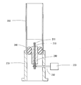
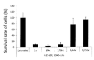
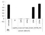
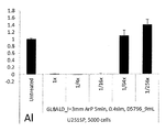
- It is a figure which shows schematic structure of the plasma generator in embodiment. It is a schematic block diagram which shows the upper structure of the plasma generator in embodiment. It is a schematic block diagram which shows the lower structure of the plasma generator in embodiment. It is a figure for demonstrating the case where the plasma generator has irradiated plasma in embodiment. It is a graph which shows the relationship between the degree of dilution of anti-tumor aqueous solution, and an anti-tumor effect in experiment. It is a graph (N 1) which shows the antitumor effect of the antitumor aqueous solution at the time of using Au as the front-end
- FIG. 1 is a conceptual diagram showing a schematic configuration of a plasma generator 1000 of the present embodiment.
- the plasma generator 1000 is for irradiating plasma to the solution stored.
- the plasma generator 1000 includes a first electrode 110, a second electrode 210, a first potential applying unit 120, a second potential applying unit 220, and a first lead wire 130.
- the first electrode 110 has a cylindrical portion 110a.
- the plasma gas can be supplied into the cylindrical portion 110a. That is, the inside of the first electrode 110 communicates with the gas supply unit 140.
- the first electrode 110 blows gas from the cylindrical portion 110a toward the second electrode 210.
- tip part of the 1st electrode 110 is carrying out the injection needle shape. That is, the tip of the first electrode 110 has an inclined surface that is inclined from a direction perpendicular to the axial direction of the first electrode 110.
- a micro hollow is formed at the tip of the first electrode 110.
- the second electrode 210 is an electrode facing the first electrode 110.
- the second electrode 210 is a rod-shaped electrode.
- the second electrode 210 has a cylindrical shape. Alternatively, it may be a polygonal column shape. Alternatively, it may have a needle shape with a sharp tip.
- the second electrode 210 has a tip portion 211.
- the tip 211 of the second electrode 210 is a metal or alloy containing at least one of Au, Pt, Ni, Al, Cu, and Fe. As will be described later, among these materials, Au is optimal for the tip end portion 211 of the second electrode 210.
- An antitumor high aqueous solution manufactured using Au at the tip portion 211 shows the highest antitumor effect.
- the tip 211 may be a metal or alloy containing iridium, osmium, or palladium. Further, at the time of discharging, the second electrode 210 is immersed in the solution stored in the container 250.
- the first potential applying unit 120 is for applying a periodically changing potential to the first electrode 110.
- the second potential applying unit 220 is for applying a periodically changing potential to the second electrode 210.
- one of the first potential applying unit 120 and the second potential applying unit 220 may be grounded.
- the first lead wire 130 is for electrically connecting the first electrode 110 and the first potential applying unit 120.
- the first lead wire 130 may be a nickel alloy or stainless steel.
- the second lead wire 230 is for electrically connecting the second electrode 210 and the second potential applying unit 220.
- the second lead wire 230 may be a nickel alloy or stainless steel.
- a high-frequency voltage is applied between the first electrode 110 and the second electrode 210. That is, the first potential application unit 120 and the second potential application unit 220 are voltage application units for applying a voltage between the first electrode 110 and the second electrode 210.
- the plasma generation apparatus 1000 includes the gas supply unit 140, the gas pipe coupling connector 150, and the gas pipe 160. Therefore, the gas supply unit 140 supplies the plasma gas to the inside of the cylindrical part 110 a of the first electrode 110 via the gas pipe 160 and the gas pipe coupling connector 150.
- the gas supply unit 160 supplies, for example, Ar gas. Alternatively, other rare gas may be supplied. Alternatively, it may contain a small amount of other gas such as oxygen gas. Therefore, the plasma gas is sprayed from the first electrode 110 toward the solution stored in the solution 250.
- FIG. 2 is a diagram showing an upper structure of the plasma generator 1000.
- the first electrode 110 has a tip 111.
- the distal end portion 111 is disposed at a position facing the second electrode 210.
- the tip 111 of the first electrode 110 has an inclined surface 111a.
- the inclined surface 111 a is a surface that is inclined with respect to a surface perpendicular to the axial direction of the first electrode 110.
- a micro hollow 111b is formed at the tip 111.
- the micro hollow 111b is a minute recess having a length of 0.5 mm to 1 mm and a width of 0.3 mm to 0.5 mm.
- the plasma generator 1000 includes the sealing member 191 and the coupling member 192.
- the sealing member 191 is attached to the container 250 shown in FIG. 1 and seals the inside of the container 250.
- the coupling member 192 is a member for connecting the first electrode 110 and the gas pipe coupling connector 150 via the sealing member 191 or the like.
- FIG. 3 is a view showing the lower structure of the plasma generating apparatus 1000.
- the plasma generation apparatus 1000 includes the container 250, the sealing member 260, and the gantry 270.
- the container 250 can accommodate a solution therein.
- the solution includes an aqueous solution such as a culture solution and other aqueous solutions and organic solvents.
- the container 250 houses the first electrode 110 and the second electrode 210 therein.
- the container 250 is good to have a scale. This is for measuring the amount of the solution stored in the container 250.
- the sealing member 260 is for closing the gap between the second electrode protection member 240 and the container 250.
- An example of the sealing member 260 is O-ring.
- Other members may be applied as long as the sealing property of the container 250 is ensured and the solution prevents the solution from leaking to the bottom of the container 250.
- the gantry 270 is for supporting the container 250 and other members.
- FIG. 4 is a diagram schematically showing how the plasma generator 1000 generates plasma.
- the plasma generated by the plasma generator 1000 is non-equilibrium atmospheric pressure plasma.
- atmospheric pressure plasma refers to plasma having a pressure in the range of 0.5 to 2.0 atmospheres.
- the plasma gas supplied from the gas supply unit 140 is released from the first electrode 110 in the direction of the arrow K1.
- a plasma generation region PG1 is formed between the first electrode 110 and the second electrode 210.
- the second electrode 210 is disposed inside the liquid. ing. As described above, between the first electrode 110 and the second electrode 210, there are the liquid stored in the container 250 and the atmosphere. A line connecting the first electrode and the second electrode intersects the liquid level LL1 of the liquid.
- plasma is generated between the liquid level LL 1 of the liquid and the first electrode 110.
- the liquid level LL1 of the liquid is recessed toward the liquid side due to the wind pressure of the plasma gas discharged from the first electrode 110 in the direction of the arrow K1.
- the solution is partially electrolyzed and vaporized inside the liquid.
- Plasma is also generated inside the vaporized gas.
- Plasma generation region PG1 is in contact with liquid level LL1.
- radicals derived from the atmosphere or water are generated. And a radical will be irradiated to a solution. Thereby, radicals react with water molecules or solutes in solution.
- the plasma generator 1000 of the present embodiment emits plasma gas from the first electrode 110. Therefore, there is almost no possibility that the plasma gas flows backward. Further, there is almost no possibility that gas generated by evaporation of the liquid enters the first electrode 110. Thus, backflow can be suppressed. That is, electrode deterioration due to backflow can be suppressed.
- the plasma generation region PG1 is limited between the first electrode 110 and the second electrode 210. Therefore, the plasma generation region PG1 does not spread more than necessary. Therefore, useless heat generation can be suppressed.
- the plasma generator 1000 can directly irradiate the liquid with plasma. Therefore, the generated radical can be suitably supplied to the liquid. Therefore, an antitumor aqueous solution having a high antitumor effect can be produced.
- the plasma generator 1000 of this embodiment is suitable for producing an antitumor aqueous solution.
- This anti-tumor aqueous solution kills cancer cells and hardly damages normal cells. That is, the anti-tumor aqueous solution can selectively kill cancer cells.
- the plasma generator 1000 of this embodiment can directly irradiate the aqueous solution with radicals. Therefore, this plasma generator 1000 is suitable for producing an antitumor aqueous solution.
- the anti-tumor aqueous solution is obtained by irradiating the first aqueous solution, which is a raw material, with atmospheric pressure plasma.
- the solvent of the first aqueous solution is an aqueous solvent.
- As the solute of the first aqueous solution disodium hydrogen phosphate (Na 2 HPO 4 ), sodium hydrogen carbonate (NaHCO 3 ), L-glutamine, L-histidine, and L-histidine.
- a solute containing at least one of L-tyrosine disodium dihydrate (L-tyrosine ⁇ 2Na ⁇ 2H 2 O) may be used.
- a culture solution can be used as the first aqueous solution.
- An example of the culture solution is DMEM.
- DMEM contains sugars such as glucose.
- the culture component is a component contained in a culture solution for culturing cells and the like.
- antitumor aqueous solution As shown in Patent Document 3 described above, this anti-tumor aqueous solution has an anti-tumor effect that selectively kills cancer cells. In addition, as described above, the antitumor aqueous solution of the present embodiment hardly damages normal cells. Therefore, this antitumor aqueous solution can be used as an anticancer agent having an anticancer effect.
- Aqueous solution preparation step (first method) The first method will be described. First, a first aqueous solution is prepared. The first aqueous solution refers to an aqueous solution before being irradiated with plasma. In this first method, a culture solution is prepared as a first aqueous solution. That is, a culture solution in which culture components are added to water is prepared. The pH of the culture solution at this stage is approximately 7. The pH is, for example, in the range of 5.5 or more and 8.5 or less.
- the first aqueous solution (culture solution) is irradiated with atmospheric pressure plasma generated in the plasma generation region by the plasma generator 1000.
- the first electrode 110 is disposed outside the first aqueous solution, and the second electrode 210 is disposed in the first aqueous solution.
- gas is irradiated from the first electrode 110 toward the first aqueous solution. In this state, a voltage is applied between the first electrode 110 and the second electrode 210.
- the distance between the liquid surface and the plasma outlet when irradiating plasma is in the range of 3 mm to 15 mm. Preferably, it exists in the range of 4 mm or more and 8 mm or less. More preferably, it exists in the range of 5 mm or more and 7 mm or less.
- the first aqueous solution (culture solution) is changed to the second aqueous solution (culture solution) by irradiating the first aqueous solution (culture solution) with plasma.
- the pH of the first aqueous solution (culture solution) before plasma irradiation is close to 7. For example, it is in the range of 5.5 or more and 8.5 or less.
- the culture solution contains a substance that attempts to maintain the pH in the vicinity of 7. For example, hydrogen carbonate ions. Therefore, the pH of this aqueous solution hardly changes before and after plasma irradiation.
- the pH of the second aqueous solution (culture solution) after plasma irradiation is close to 7.
- the pH is, for example, in the range of 5.5 or more and 8.5 or less.
- first aqueous solution is prepared.
- the first aqueous solution refers to an aqueous solution before being irradiated with plasma.
- second method the following aqueous solution is prepared as the first aqueous solution.
- disodium hydrogen phosphate Na 2 HPO 4
- sodium bicarbonate NaHCO 3
- L-glutamine L-histidine
- L-tyrosine disodium A first aqueous solution in which a solute containing at least one of dihydrate (L-Tyrosine ⁇ 2Na ⁇ 2H 2 O) is added to water is prepared.
- the first aqueous solution is irradiated with atmospheric pressure plasma generated in the plasma generation region by the plasma generator 1000.
- Various conditions for plasma irradiation are the same as in the first method.
- the second aqueous solution is produced by irradiating the first aqueous solution with plasma.
- Culture component addition step Next, a culture component is added to the second aqueous solution.
- the aqueous solution obtained by adding the culture components to the second aqueous solution is also referred to as the second aqueous solution.
- Experiment A Anti-tumor effect in anti-tumor aqueous solution
- This experiment is an experiment conducted on an anti-tumor aqueous solution manufactured using the plasma generator 1000 of the present embodiment.
- glioma was used as a cancer cell.
- Glioma is a glioma that develops in glial cells (glial cells). That is, it is a kind of brain tumor.
- U251SP was used as the glioma.
- the above cancer cells were cultured in a 96-well plate to prepare a cancer cell culture medium.
- the culture solution used is a solution in which DMEM, serum (FBS) and antibiotics (penicillin / streptomycin) are mixed.
- the number of cells seeded per well is 5000.
- the volume of the culture solution supplied per well was 200 ⁇ L.
- the culture period for culturing cancer cells was 24 hours.
- the culture components contained in DMEM are calcium chloride, ferric nitrate ⁇ 9H 2 O, magnesium sulfate (anhydrous), potassium chloride, sodium hydrogen carbonate, sodium chloride, monosodium phosphate (anhydrous), L-arginine.
- HCl L-cystine ⁇ 2HCl, L-glutamine, glycine, L-histidine ⁇ HCl ⁇ H 2 O, L-isoleucine, L-leucine, L-lysine ⁇ HCl, L-methionine, L-phenylalanine, L-serine L-threonine, L-tryptophan, L-tyrosine ⁇ 2Na ⁇ 2H 2 O, L-valine, choline chloride, folic acid, myo-inositol, niacinamide, D-pantothenic acid, pyridoxine ⁇ HCl, riboflavin, thiamine ⁇ HCl, D-glucose, phenol red and Na.
- the culture solution used here is a solution obtained by mixing the aforementioned DMEM, serum (FBS) and antibiotics (penicillin / streptomycin).
- the components of DMEM are as described above.
- This culture solution was accommodated in the container 250 of the plasma generator 1000. And using the plasma generator 1000, the culture solution was irradiated with plasma.
- the plasma irradiation time was 3 minutes.
- the gas flow rate was 0.4 slm.
- Argon gas was used as the type of gas.
- the distance between the first electrode 110 and the liquid level LL1 was 6 mm.
- the distance between the first electrode 110 and the liquid level LL1 is a distance before the plasma gas is supplied. That is, the portion in which the liquid level LL1 is recessed due to the supply of gas is not retracted. Thereby, an antitumor aqueous solution was produced.
- FIG. 5 represents the ratio of the number of viable cells.
- “Untreated” is the viable cell rate of cancer cells when plasma is not irradiated. This case was taken as 100% of the standard.
- the anti-tumor aqueous solution when used as an undiluted aqueous solution, a 4-fold diluted aqueous solution, or a 16-fold diluted aqueous solution, the ratio of the number of viable cancer cells was 10% or less. Met. That is, these aqueous solutions showed a strong antitumor effect.
- the ratio of the number of cancer cells surviving was about 75%.
- the ratio of the number of viable cancer cells was about 90%. That is, these aqueous solutions did not show much antitumor effect.
- the anti-tumor aqueous solution produced using the plasma generator 1000 of the present embodiment exhibited a strong anti-tumor effect even when diluted 16 times. Therefore, this plasma generator 1000 is very suitable for producing an antitumor aqueous solution.
- Experiment B material for the tip of the second electrode 7-1.
- Type of electrode material An antitumor aqueous solution was manufactured by applying Au, Pt, Ni, Al, Cu, and Fe as the tip 211 of the second electrode 210. And the strength of the antitumor effect of those antitumor aqueous solution was measured. Moreover, the corrosion state of each electrode material was observed.
- the cancer cell was U251SP. The number of cells seeded per well was 5000. The plasma irradiation time was 5 minutes.
- FIG. 7 1) showing the antitumor effect of the antitumor aqueous solution when Pt is used as the tip portion 211 of the second electrode 210.
- the antitumor aqueous solution diluted 16 times or less showed a high antitumor effect even when any material was used as the tip 211 of the second electrode 210. That is, when these anti-tumor aqueous solutions were used, the survival rate of glioma was almost zero.
- the survival rate of glioma was about 40% when Au was used.
- the survival rate of glioma was about 80% when Pt, Ni, and Fe were used.
- the survival rate of glioma was about 100% when Al and Cu were used. Therefore, in view of the strength of the antitumor effect, it is most preferable to use Au as the tip portion 211 of the second electrode 210.
- FIG. 14 is a graph (N
- the number of samples (N number) is 4, the durability of the tip end portion 211 of the second electrode 210 was examined.
- N number the number of samples (N number) is 4, the durability of the tip end portion 211 of the second electrode 210 was examined.
- the survival rate of glioma was almost zero when Au, Pt, Ni, and Al were used.
- the anti-tumor aqueous solution diluted 16 times had a glioma survival rate of about 80% when Cu or Fe was used.
- the antitumor aqueous solution diluted 8 times the survival rate of glioma was almost zero when Au, Pt, Ni, Al, and Cu were used.
- the survival rate of glioma was about 80% when Fe was used.
- the antitumor effect of the produced antitumor aqueous solution was reduced by repeating the discharge. That is, Au, Pt, Ni, and Al are more durable than Cu and Fe.
- FIG. 18 is a photograph showing the second electrode 210 when Au is used as the tip portion 211 of the second electrode 210.
- FIG. 19 is a photograph showing the second electrode 210 when Pt is used as the tip end portion 211 of the second electrode 210.
- FIG. 20 is a photograph showing the second electrode 210 when Ni is used as the tip portion 211 of the second electrode 210.
- FIG. 21 is a photograph showing the second electrode 210 when Al is used as the tip end portion 211 of the second electrode 210.
- FIG. 22 is a photograph showing the second electrode 210 when Cu is used as the tip 211 of the second electrode 210.
- FIG. 23 is a photograph showing the second electrode 210 when Fe is used as the tip portion 211 of the second electrode 210.
- Au is most suitable as the tip 211 of the second electrode 210. This is because the anti-tumor effect of an anti-tumor aqueous solution produced using Au is high, and Au is not easily corroded.
- Pt and Ni are preferable. Al, Cu, and Fe are more easily corroded than Au, Pt, and Ni, but are not necessarily not applicable as the tip 211 of the second electrode 210.
- the work function of Au, Pt, and Ni is 5 eV or more.
- the work function of Al, Cu, and Fe is about 4.5 eV.
- a metal having a high work function such as Au
- a process is performed in which charged particles having high energy collide with the surface of the tip portion 211 of the second electrode 210 to excite and emit electrons inside the tip portion 211.
- the charged particles are accelerated by the voltage drop part in the vicinity of the tip part 211.
- a metal having a high work function such as Au forms a steeper voltage drop. Therefore, it is considered that a plasma product is generated more efficiently in a metal having a high work function.
- the plasma generator 1000 is applied to the application of irradiating the culture solution with plasma.
- the plasma generator 1000 can also be used when other liquids are irradiated with high-density plasma. That is, of course, it may be used for purposes other than manufacturing an antitumor aqueous solution.
- the cylindrical part 110a of the 1st electrode 110 is cylindrical shape. However, it is not limited to a cylindrical shape. As long as it is cylindrical, it may be polygonal.
- the plasma generator 1000 of the present embodiment includes the cylindrical first electrode 110 and the rod-shaped second electrode 210 facing the first electrode 110 across the liquid surface. And have. Further, the tip 111 of the first electrode 110 has an inclined surface 111a that is inclined with respect to a surface perpendicular to the axial direction of the first electrode 110, and a micro hollow 111b. Therefore, this plasma generator 1000 can generate high-density plasma. This plasma generator 1000 is suitable for producing an antitumor aqueous solution that can kill cancer cells with little effect on normal cells.
Landscapes
- Physics & Mathematics (AREA)
- Engineering & Computer Science (AREA)
- Plasma & Fusion (AREA)
- Spectroscopy & Molecular Physics (AREA)
- Medicines That Contain Protein Lipid Enzymes And Other Medicines (AREA)
- Pharmaceuticals Containing Other Organic And Inorganic Compounds (AREA)
- Plasma Technology (AREA)
Abstract
【課題】 正常細胞にほとんど影響を与えることなく癌細胞を死滅させることのできる抗腫瘍水溶液の製造に好適なプラズマ発生装置および抗腫瘍水溶液の製造方法を提供することである。 【解決手段】 プラズマ発生装置1000は、筒形状部を備える第1電極110と、第1電極110と対向する第2電極210と、第1電極110の筒形状部の内部にガスを供給するガス供給部140と、を有する。また、第1電極110は、筒形状部から第2電極210に向けてガスを流す。
Description
本明細書の技術分野は、プラズマ発生装置および抗腫瘍水溶液の製造方法に関する。さらに詳細には、癌細胞を死滅させることのできる抗腫瘍水溶液の製造に好適なプラズマ発生装置および抗腫瘍水溶液の製造方法に関するものである。
プラズマ技術は、電気、化学、材料の各分野に応用されている。そして、近年においては、医療への応用が活発に研究されるようになってきた。プラズマの内部では、電子やイオン等の荷電粒子の他に、紫外線やラジカルが発生する。これらには、生体組織の殺菌をはじめとして、生体組織に対する種々の効果があることが分かってきている。
例えば、特許文献1には、プラズマの照射により、血液凝固(特許文献1の実施例4、段落[0063]-[0068]参照)と、組織滅菌(特許文献1の実施例5、段落[0069]-[0074]参照)と、リーシュマニア症(特許文献1の実施例6、段落[0075]-[0077]参照)とに対して、効果があることが記載されている。そして、メラノーマ細胞(悪性黒色腫細胞)を死滅させる効果があると記載されている(特許文献1の実施例7、段落[0078]参照)。
また、特許文献2には、pHが4.8以下となるように調整された液体にプラズマを照射することにより、液体中の菌を殺菌する技術が開示されている(特許文献2の段落[0020]等参照)。また、スーパーオキシドアニオンラジカルやヒドロペルオキシラジカル等が殺菌効果を担っている可能性がある旨が記載されている(特許文献2の段落[0090]-[0099]等参照)。
ところで、このような癌の治療においては一般に、1)癌細胞を死滅させるとともに、2)正常細胞に影響を与えないように、癌細胞を選択的に死滅させることが好ましい。たとえ、癌細胞を死滅させることができたとしても、そのために多数の正常細胞を死滅させると、患者に加わる肉体的負担が大きいからである。そのため、このように癌細胞を選択的に死滅させる治療技術が望まれている。しかし、癌細胞を選択的に死滅させることは容易ではない。そして、特許文献1では、正常細胞への影響の程度が明らかではない。
そのため特許文献3に記載されているように、本発明者らは、癌細胞を選択的に死滅させる抗腫瘍水溶液に関する技術を研究開発した(特許文献3の段落[0085]-[0087]および図16等参照)。この抗腫瘍水溶液は、癌細胞を選択的に死滅させることができる。また、この抗腫瘍水溶液は、培養した細胞のみならずマウスに対しても抗腫瘍効果を発揮した(特許文献3の段落[0145]-[0152]および図45、46等参照)。
もちろん、より抗腫瘍効果に優れた抗腫瘍水溶液を製造することが好ましい。抗腫瘍効果の高い抗腫瘍水溶液を得るためには、プラズマ密度の高いプラズマを抗腫瘍水溶液の原材料に供給することが好ましい。
本明細書の技術は、前述した従来の技術が有する問題点を解決するためになされたものである。すなわちその課題とするところは、正常細胞にほとんど影響を与えることなく癌細胞を死滅させることのできる抗腫瘍水溶液の製造に好適なプラズマ発生装置および抗腫瘍水溶液の製造方法を提供することである。
第1の態様におけるプラズマ発生装置は、筒形状部を備える第1電極と、第1電極と対向する第2電極と、第1電極の筒形状部の内部にガスを供給するガス供給部と、を有する。また、第1電極は、筒形状部から第2電極に向けてガスを流す。
このプラズマ発生装置は、第1電極の筒形状部の内部から第2電極に向かってプラズマガスを放出することができる。そのため、プラズマ密度の高いプラズマを液体に照射することができる。つまり、プラズマの内部で発生させたラジカルを好適に液体に照射することができる。これにより、抗腫瘍効果に優れた抗腫瘍水溶液を製造することができる。ここで、液体とは、水溶液、非水溶液、水、非水系溶媒を含むものとする。
第2の態様におけるプラズマ発生装置は、第1電極と第2電極とを収容するとともに液体を収容する容器と、第1電極と第2電極との間に電圧を印加する電圧印加部と、を有する。電圧印加部が、第1電極と第2電極との間に電圧を印加する電圧印加時には、第2電極は、液体の内部に配置されている。
このプラズマ発生装置では、第1電極が大気中に配置されるとともに、第2電極が液中に配置されている。そのため、液体の液面をはさんで第1電極および第2電極が対向して配置されることとなる。したがって、プラズマ生成領域が液体に接することとなる。これにより、液体に多量のラジカルを照射することができる。
第3の態様におけるプラズマ発生装置においては、第1電極と第2電極とを結ぶ線が、液体の液面と交差している。また、第1電極から流れるガスが、液体の液面を凹ませる。
第4の態様におけるプラズマ発生装置においては、第2の電極は、棒状電極である。
第5の態様におけるプラズマ発生装置においては、棒状電極の先端は、Au、Pt、Ni、Al、Cu、Feのうちの少なくとも一種類以上を含む金属もしくは合金である。
第6の態様におけるプラズマ発生装置においては、第1の電極は、先端部を有する。また、先端部は、第1電極の軸方向に垂直な面に対して傾斜する傾斜面を有する。
第7の態様におけるプラズマ発生装置においては、先端部は、マイクロホローを有する。
第8の態様における抗腫瘍水溶液の製造方法は、リン酸水素二ナトリウム(Na2 HPO4 )と、炭酸水素ナトリウム(NaHCO3 )と、L-グルタミン(L-Glutamine)と、L-ヒスチジン(L-Histidine)と、L-チロシン二ナトリウム二水和物(L-Tyrosine・2Na・2H2 O)とのうちの少なくとも1種類を含む溶質を水に添加した第1の水溶液を準備する水溶液準備工程と、第1の水溶液にプラズマを照射するプラズマ照射工程と、を有する。プラズマ照射工程では、第1電極を第1の水溶液の外に配置するとともに第2電極を第1の水溶液の中に配置し、第1電極から第1の水溶液に向かってガスを照射し、その状態で第1電極と第2電極との間に電圧を印加する。
本明細書では、正常細胞にほとんど影響を与えることなく癌細胞を死滅させることのできる抗腫瘍水溶液の製造に好適なプラズマ発生装置および抗腫瘍水溶液の製造方法が提供されている。
以下、具体的な実施形態について、プラズマ発生装置および抗腫瘍水溶液の製造方法を例に挙げて図を参照しつつ説明する。
1.プラズマ発生装置
図1は、本実施形態のプラズマ発生装置1000の概略構成を示す概念図である。プラズマ発生装置1000は、収容している溶液にプラズマを照射するためのものである。
図1は、本実施形態のプラズマ発生装置1000の概略構成を示す概念図である。プラズマ発生装置1000は、収容している溶液にプラズマを照射するためのものである。
図1に示すように、プラズマ発生装置1000は、第1電極110と、第2電極210と、第1の電位付与部120と、第2の電位付与部220と、第1のリード線130と、第2のリード線230と、ガス供給部140と、ガス管結合コネクター150と、ガス管160と、第1電極保護部材170と、第2電極保護部材240と、第1電極支持部材180と、密閉部材191と、結合部材192と、容器250と、封止部材260と、架台270と、を有している。
1-1.電極の概略構成
第1電極110は、筒形状部110aを有している。そして、その筒形状部110aの内部にプラズマガスを供給することができるようになっている。つまり、第1電極110の内部は、ガス供給部140と連通している。第1電極110は、筒形状部110aから第2電極210に向けてガスを吹き出すようになっている。そして、第1電極110の先端部は、注射針形状をしている。つまり、第1電極110の先端部は、第1電極110の軸方向に垂直な方向から傾斜する傾斜面を有している。そして、第1電極110の先端部には、マイクロホローが形成されている。
第1電極110は、筒形状部110aを有している。そして、その筒形状部110aの内部にプラズマガスを供給することができるようになっている。つまり、第1電極110の内部は、ガス供給部140と連通している。第1電極110は、筒形状部110aから第2電極210に向けてガスを吹き出すようになっている。そして、第1電極110の先端部は、注射針形状をしている。つまり、第1電極110の先端部は、第1電極110の軸方向に垂直な方向から傾斜する傾斜面を有している。そして、第1電極110の先端部には、マイクロホローが形成されている。
第2電極210は、第1電極110と対向する電極である。第2電極210は、棒状電極である。第2電極210は、円柱形状である。もしくは、多角柱形状であってもよい。もしくは、先端の尖った針形状であってもよい。ここで、第2電極210は、先端部211を有している。第2電極210の先端部211は、Au、Pt、Ni、Al、Cu、Feのうちの少なくとも一種類以上を含む金属もしくは合金である。後述するように、第2電極210の先端部211として、これらの材料のうちAuが最適である。先端部211にAuを用いて製造された抗腫瘍高水溶液が、最も高い抗腫瘍効果を示す。また、Au、Pt、Niは、その他の材料に比べて腐食しにくい。先端部211として、イリジウム、オスミウム、パラジウムを含む金属もしくは合金であってもよい。また、放電時には、第2電極210は、容器250に収容されている溶液に浸かっている。
第1の電位付与部120は、第1電極110に周期的に変化する電位を付与するためのものである。第2の電位付与部220は、第2電極210に周期的に変化する電位を付与するためのものである。ここで、第1の電位付与部120と第2の電位付与部220とのうちのどちらか一方は、接地されていてもよい。第1のリード線130は、第1電極110と第1の電位付与部120とを電気的に接続するためのものである。第1のリード線130は、ニッケル合金もしくはステンレスであるとよい。第2のリード線230は、第2電極210と第2の電位付与部220とを電気的に接続するためのものである。第2のリード線230は、ニッケル合金もしくはステンレスであるとよい。これにより、第1電極110と第2電極210との間に高周波の電圧が印加されることとなる。つまり、第1の電位付与部120および第2の電位付与部220は、第1電極110と第2電極210との間に電圧を印加するための電圧印加部である。
1-2.ガス供給経路
プラズマ発生装置1000は、前述したように、ガス供給部140と、ガス管結合コネクター150と、ガス管160と、を有している。そのため、ガス供給部140は、ガス管160およびガス管結合コネクター150を介して、第1電極110の筒形状部110aの内部にプラズマガスを供給する。ここで、ガス供給部160は、例えば、Arガスを供給する。もしくは、その他の希ガスを供給してもよい。もしくは、酸素ガス等その他のガスを微量含んでいてもよい。そのため、プラズマガスは、第1電極110から溶液250に収容されている溶液に向けて吹き付けられることとなる。
プラズマ発生装置1000は、前述したように、ガス供給部140と、ガス管結合コネクター150と、ガス管160と、を有している。そのため、ガス供給部140は、ガス管160およびガス管結合コネクター150を介して、第1電極110の筒形状部110aの内部にプラズマガスを供給する。ここで、ガス供給部160は、例えば、Arガスを供給する。もしくは、その他の希ガスを供給してもよい。もしくは、酸素ガス等その他のガスを微量含んでいてもよい。そのため、プラズマガスは、第1電極110から溶液250に収容されている溶液に向けて吹き付けられることとなる。
1-3.上部構造の構成
図2は、プラズマ発生装置1000の上部構造を示す図である。図2に示すように、第1電極110は、先端部111を有している。先端部111は、図1に示すように、第2電極210に対面する位置に配置されている。第1電極110の先端部111は、傾斜面111aを有している。傾斜面111aは、第1電極110の軸方向に垂直な面に対して傾斜している面である。また、先端部111には、マイクロホロー111bが形成されている。マイクロホロー111bは、長さ0.5mm以上1mm以下、幅0.3mm以上0.5mm以下の微小な凹部である。
図2は、プラズマ発生装置1000の上部構造を示す図である。図2に示すように、第1電極110は、先端部111を有している。先端部111は、図1に示すように、第2電極210に対面する位置に配置されている。第1電極110の先端部111は、傾斜面111aを有している。傾斜面111aは、第1電極110の軸方向に垂直な面に対して傾斜している面である。また、先端部111には、マイクロホロー111bが形成されている。マイクロホロー111bは、長さ0.5mm以上1mm以下、幅0.3mm以上0.5mm以下の微小な凹部である。
また、前述したように、プラズマ発生装置1000は、密閉部材191と、結合部材192と、を有している。密閉部材191は、図1に示す容器250に取り付けるとともに容器250の内部を密閉するためのものである。結合部材192は、第1電極110とガス管結合コネクター150とを、密閉部材191等を介して連結するための部材である。
1-4.下部構造の構成
図3は、プラズマ発生装置1000の下部構造を示す図である。前述したように、プラズマ発生装置1000は、容器250と、封止部材260と、架台270と、を有している。容器250は、内部に溶液を収容することができるようになっている。ここで、溶液とは、培養液等の水溶液、その他の水溶液や有機溶剤をも含むこととする。また、容器250は、第1電極110および第2電極210を内部に収容している。また、容器250は、目盛を有しているとよい。容器250の内部に収容されている溶液の量を計量するためである。
図3は、プラズマ発生装置1000の下部構造を示す図である。前述したように、プラズマ発生装置1000は、容器250と、封止部材260と、架台270と、を有している。容器250は、内部に溶液を収容することができるようになっている。ここで、溶液とは、培養液等の水溶液、その他の水溶液や有機溶剤をも含むこととする。また、容器250は、第1電極110および第2電極210を内部に収容している。また、容器250は、目盛を有しているとよい。容器250の内部に収容されている溶液の量を計量するためである。
封止部材260は、第2電極保護部材240と、容器250との間の隙間を塞ぐためのものである。封止部材260として、例えば、オーリングが挙げられる。容器250の密閉性を確保し、溶液が容器250の底部に漏れ出すのを防止するものであれば、これ以外の部材を適用してもよい。架台270は、容器250その他の各部材を支持するためのものである。
2.プラズマ発生装置により発生されるプラズマ
図4は、プラズマ発生装置1000がプラズマを発生させている様子を模式的に示す図である。プラズマ発生装置1000により発生されるプラズマは、非平衡大気圧プラズマである。ここで、大気圧プラズマとは、0.5気圧以上2.0気圧以下の範囲内の圧力であるプラズマをいう。
図4は、プラズマ発生装置1000がプラズマを発生させている様子を模式的に示す図である。プラズマ発生装置1000により発生されるプラズマは、非平衡大気圧プラズマである。ここで、大気圧プラズマとは、0.5気圧以上2.0気圧以下の範囲内の圧力であるプラズマをいう。
図4に示すように、ガス供給部140から供給されるプラズマガスは、第1電極110から矢印K1の向きに放出される。そして、第1電極110と第2電極210との間に高周波の電圧を印加すると、第1電極110と第2電極210との間にプラズマ発生領域PG1が形成される。
第1の電位付与部120および第2の電位付与部220が、第1電極110と第2電極210との間に電圧を印加する電圧印加時には、第2電極210は、液体の内部に配置されている。このように、第1電極110と第2電極210との間には、容器250に収容されている液体と大気とがある。そして、第1電極と第2電極とを結ぶ線が、液体の液面LL1と交差している。
そのため、液体の液面LL1と第1電極110との間にプラズマが発生する。このとき、液体の液面LL1は、第1電極110から矢印K1の向きに放出されるプラズマガスの風圧を受けて、液体の側に向かって凹んでいる。そして、液体の内部では溶液が部分的に電気分解し、気化する。その気化したガスの内部でもプラズマが発生する。また、プラズマ発生領域PG1は、液体の液面LL1に接触している。
以上により、大気もしくは水に由来するラジカルが発生する。そして、溶液にラジカルが照射されることとなる。これにより、ラジカルは、水分子もしくは溶液中の溶質と反応する。
3.プラズマ発生装置の効果
本実施形態のプラズマ発生装置1000は、第1電極110からプラズマガスを放出する。そのため、プラズマガスが逆流するおそれがほとんどない。また、液体が蒸発することにより発生するガスが、第1電極110の内部に入るおそれもほとんどない。このように、バックフローを抑制することができる。つまり、バックフローによる電極の劣化を抑制することができる。
本実施形態のプラズマ発生装置1000は、第1電極110からプラズマガスを放出する。そのため、プラズマガスが逆流するおそれがほとんどない。また、液体が蒸発することにより発生するガスが、第1電極110の内部に入るおそれもほとんどない。このように、バックフローを抑制することができる。つまり、バックフローによる電極の劣化を抑制することができる。
また、プラズマ発生装置1000では、プラズマ発生領域PG1が、第1電極110と第2電極210との間に限られる。そのため、プラズマ発生領域PG1が必要以上に広がることがない。したがって、無駄な発熱を抑制することができる。
また、プラズマ発生装置1000は、プラズマを液体に直接照射することができる。そのため、発生するラジカルを好適に液体に供給することができる。したがって、抗腫瘍効果の高い抗腫瘍水溶液を製造することができる。
4.プラズマ発生装置の適用例
4-1.抗腫瘍水溶液
本実施形態のプラズマ発生装置1000は、抗腫瘍水溶液を作製するのに好適である。この抗腫瘍水溶液は、癌細胞を死滅させるとともに正常細胞にダメージをほとんど与えない。つまり、抗腫瘍水溶液は、癌細胞を選択的に死滅させることができる。本実施形態のプラズマ発生装置1000は、水溶液に直接的にラジカルを照射することができる。そのため、このプラズマ発生装置1000は、抗腫瘍水溶液を作製するのに適している。
4-1.抗腫瘍水溶液
本実施形態のプラズマ発生装置1000は、抗腫瘍水溶液を作製するのに好適である。この抗腫瘍水溶液は、癌細胞を死滅させるとともに正常細胞にダメージをほとんど与えない。つまり、抗腫瘍水溶液は、癌細胞を選択的に死滅させることができる。本実施形態のプラズマ発生装置1000は、水溶液に直接的にラジカルを照射することができる。そのため、このプラズマ発生装置1000は、抗腫瘍水溶液を作製するのに適している。
後述するように、抗腫瘍水溶液は、原材料である第1の水溶液に大気圧プラズマを照射したものである。第1の水溶液の溶媒は、水系溶媒である。第1の水溶液の溶質として、リン酸水素二ナトリウム(Na2 HPO4 )と、炭酸水素ナトリウム(NaHCO3 )と、L-グルタミン(L-Glutamine)と、L-ヒスチジン(L-Histidine)と、L-チロシン二ナトリウム二水和物(L-Tyrosine・2Na・2H2 O)とのうちの少なくとも1種類を含む溶質を用いればよい。または、第1の水溶液として、培養液を用いることもできる。培養液として、例えば、DMEMが挙げられる。そして、DMEMには、グルコース等の糖が含まれている。ここで、培養成分とは、細胞等を培養するための培養液に含まれる成分である。
4-2.抗腫瘍水溶液の性質および用途(抗癌剤)
この抗腫瘍水溶液は、前述した特許文献3に示すように、癌細胞を選択的に死滅させる抗腫瘍効果を有する。また、本実施形態の抗腫瘍水溶液は、前述したように、正常細胞にはほとんどダメージを与えない。そのため、この抗腫瘍水溶液について、抗癌作用を有する抗癌剤として用いることができる。
この抗腫瘍水溶液は、前述した特許文献3に示すように、癌細胞を選択的に死滅させる抗腫瘍効果を有する。また、本実施形態の抗腫瘍水溶液は、前述したように、正常細胞にはほとんどダメージを与えない。そのため、この抗腫瘍水溶液について、抗癌作用を有する抗癌剤として用いることができる。
5.抗腫瘍水溶液の製造方法
本実施形態のプラズマ発生装置1000を用いた抗腫瘍水溶液の製造方法には、2種類の方法がある。よって、それぞれの方法について説明する。
本実施形態のプラズマ発生装置1000を用いた抗腫瘍水溶液の製造方法には、2種類の方法がある。よって、それぞれの方法について説明する。
5-1.抗腫瘍水溶液の製造方法(第1の方法)
5-1-1.水溶液準備工程(第1の方法)
第1の方法について説明する。まず、第1の水溶液を準備する。第1の水溶液とは、プラズマを照射する前の水溶液のことをいう。この第1の方法では、第1の水溶液として、培養液を準備する。つまり、水に培養成分を添加した培養液を準備する。この段階における培養液のpHは、ほぼ7である。pHは、例えば、5.5以上8.5以下の範囲内である。
5-1-1.水溶液準備工程(第1の方法)
第1の方法について説明する。まず、第1の水溶液を準備する。第1の水溶液とは、プラズマを照射する前の水溶液のことをいう。この第1の方法では、第1の水溶液として、培養液を準備する。つまり、水に培養成分を添加した培養液を準備する。この段階における培養液のpHは、ほぼ7である。pHは、例えば、5.5以上8.5以下の範囲内である。
5-1-2.プラズマ照射工程(第1の方法)
次に、プラズマ発生装置1000によりプラズマ発生領域に発生させた大気圧プラズマを第1の水溶液(培養液)に照射する。第1電極110を第1の水溶液の外に配置するとともに第2電極210を第1の水溶液の中に配置する。そして、第1電極110から第1の水溶液に向かってガスを照射する。そして、その状態で第1電極110と第2電極210との間に電圧を印加する。
次に、プラズマ発生装置1000によりプラズマ発生領域に発生させた大気圧プラズマを第1の水溶液(培養液)に照射する。第1電極110を第1の水溶液の外に配置するとともに第2電極210を第1の水溶液の中に配置する。そして、第1電極110から第1の水溶液に向かってガスを照射する。そして、その状態で第1電極110と第2電極210との間に電圧を印加する。
プラズマを照射する際における液面とプラズマ噴出口との間の距離は、3mm以上15mm以下の範囲内である。好ましくは、4mm以上8mm以下の範囲内である。より好ましくは、5mm以上7mm以下の範囲内である。
このように、第1の水溶液(培養液)にプラズマを照射することにより、第1の水溶液(培養液)を第2の水溶液(培養液)にする。プラズマ照射前の第1の水溶液(培養液)のpHは、7に近い。例えば、5.5以上8.5以下の範囲内である。一般に、培養液は、pHを7付近に保持しようとする物質を含んでいる。例えば、炭酸水素イオンである。そのため、プラズマを照射する前後で、この水溶液のpHはほとんど変化しない。プラズマ照射後の第2の水溶液(培養液)のpHは、7に近い。pHは、例えば、5.5以上8.5以下の範囲内である。
5-2.抗腫瘍水溶液の製造方法(第2の方法)
5-2-1.水溶液準備工程(第2の方法)
第2の方法について説明する。まず、第1の水溶液を準備する。第1の水溶液とは、プラズマを照射する前の水溶液のことをいう。この第2の方法では、第1の水溶液として、次の水溶液を準備する。ここでは、リン酸水素二ナトリウム(Na2 HPO4 )と、炭酸水素ナトリウム(NaHCO3 )と、L-グルタミン(L-Glutamine)と、L-ヒスチジン(L-Histidine)と、L-チロシン二ナトリウム二水和物(L-Tyrosine・2Na・2H2 O)とのうちの少なくとも1種類を含む溶質を水に添加した第1の水溶液を準備する。
5-2-1.水溶液準備工程(第2の方法)
第2の方法について説明する。まず、第1の水溶液を準備する。第1の水溶液とは、プラズマを照射する前の水溶液のことをいう。この第2の方法では、第1の水溶液として、次の水溶液を準備する。ここでは、リン酸水素二ナトリウム(Na2 HPO4 )と、炭酸水素ナトリウム(NaHCO3 )と、L-グルタミン(L-Glutamine)と、L-ヒスチジン(L-Histidine)と、L-チロシン二ナトリウム二水和物(L-Tyrosine・2Na・2H2 O)とのうちの少なくとも1種類を含む溶質を水に添加した第1の水溶液を準備する。
5-2-2.プラズマ照射工程(第2の方法)
次に、プラズマ発生装置1000によりプラズマ発生領域に発生させた大気圧プラズマを第1の水溶液に照射する。プラズマを照射する際の種々の条件は、第1の方法と同様である。このように、第1の水溶液にプラズマを照射することにより、第2の水溶液が作製される。
次に、プラズマ発生装置1000によりプラズマ発生領域に発生させた大気圧プラズマを第1の水溶液に照射する。プラズマを照射する際の種々の条件は、第1の方法と同様である。このように、第1の水溶液にプラズマを照射することにより、第2の水溶液が作製される。
5-2-3.培養成分添加工程(第2の方法)
次に、第2の水溶液に、培養成分を添加する。便宜上、この第2の水溶液に培養成分を添加した水溶液についても、同様に、第2の水溶液ということとする。
次に、第2の水溶液に、培養成分を添加する。便宜上、この第2の水溶液に培養成分を添加した水溶液についても、同様に、第2の水溶液ということとする。
6.実験A(抗腫瘍水溶液における抗腫瘍効果)
本実験は、本実施形態のプラズマ発生装置1000を用いて製造された抗腫瘍水溶液について行った実験である。
本実験は、本実施形態のプラズマ発生装置1000を用いて製造された抗腫瘍水溶液について行った実験である。
6-1.用いた癌細胞
本実験では、癌細胞としてグリオーマを用いた。グリオーマは、神経膠細胞(グリア細胞)に発生する神経膠腫である。すなわち、脳腫瘍の一種である。グリオーマとして、具体的には、U251SPを用いた。
本実験では、癌細胞としてグリオーマを用いた。グリオーマは、神経膠細胞(グリア細胞)に発生する神経膠腫である。すなわち、脳腫瘍の一種である。グリオーマとして、具体的には、U251SPを用いた。
6-2.実験方法
6-2-1.癌細胞の培養
上記の癌細胞を、96ウェルプレートに培養して癌細胞培養地を作製した。用いた培養液は、DMEMと血清(FBS)と抗生物質(ペニシリン・ストレプトマイシン)とを混合した溶液である。1ウェル当たりに播種した細胞数は5000個である。また、1ウェル当たりに供給した培養液の容積は200μLであった。癌細胞を培養する培養期間は24時間であった。
6-2-1.癌細胞の培養
上記の癌細胞を、96ウェルプレートに培養して癌細胞培養地を作製した。用いた培養液は、DMEMと血清(FBS)と抗生物質(ペニシリン・ストレプトマイシン)とを混合した溶液である。1ウェル当たりに播種した細胞数は5000個である。また、1ウェル当たりに供給した培養液の容積は200μLであった。癌細胞を培養する培養期間は24時間であった。
ここで、DMEMが含有する培養成分は、塩化カルシウム、硝酸第二鉄・9H2 O、硫酸マグネシウム(無水)、塩化カリウム、炭酸水素ナトリウム、塩化ナトリウム、リン酸一ナトリウム(無水)、L-アルギニン・HCl、L-シスチン・2HCl、L-グルタミン、グリシン、L-ヒスチジン・HCl・H2 O、L-イソロイシン、L-ロイシン、L-リジン・HCl、L-メチオニン、L-フェニルアラニン、L-セリン、L-スレオニン、L-トリプトファン、L-チロシン・2Na・2H2 O、L-バリン、塩化コリン、葉酸、myo-イノシトール、ナイアシンアミド、D-パントテン酸、ピリドキシン・HCl、リボフラビン、チアミン・HCl、D-グルコース、フェノールレッド・Naである。
6-2-2.抗腫瘍水溶液の作製
癌細胞培養地を用意するのとは別に、抗腫瘍水溶液を作製した。本実験では、第1の方法を用いた。ここで用いた培養液は、前述したDMEMと血清(FBS)と抗生物質(ペニシリン・ストレプトマイシン)とを混合した溶液である。DMEMの成分は、前述したとおりである。この培養液をプラズマ発生装置1000の容器250に収容した。そして、プラズマ発生装置1000を用いて、培養液にプラズマを照射した。
癌細胞培養地を用意するのとは別に、抗腫瘍水溶液を作製した。本実験では、第1の方法を用いた。ここで用いた培養液は、前述したDMEMと血清(FBS)と抗生物質(ペニシリン・ストレプトマイシン)とを混合した溶液である。DMEMの成分は、前述したとおりである。この培養液をプラズマ発生装置1000の容器250に収容した。そして、プラズマ発生装置1000を用いて、培養液にプラズマを照射した。
プラズマの照射時間は、3分であった。ガスの流量は、0.4slmであった。ガスの種類としてアルゴンガスを用いた。また、第1電極110と液面LL1との間の距離は、6mmであった。ここで、第1電極110と液面LL1との間の距離とは、プラズマガスを供給する前の距離である。つまり、ガスの供給により、液面LL1が凹む部分については繰り込まれていない。これにより、抗腫瘍水溶液が作製された。
そして、抗腫瘍水溶液について、プラズマを照射していない同じ成分の培養液で、4倍、16倍、64倍、256倍に希釈したものを用意した。
6-2-3.癌細胞培養地への抗腫瘍水溶液の供給
次に、癌細胞を培養した96ウェルプレートの培養液を抗腫瘍水溶液と交換した。癌細胞が抗腫瘍水溶液に浸かっている時間は、24時間であった。そして、その後、抗腫瘍水溶液を通常の培養液に交換した。その後、MTSアッセイにより、生存している細胞数の割合を調べた。
次に、癌細胞を培養した96ウェルプレートの培養液を抗腫瘍水溶液と交換した。癌細胞が抗腫瘍水溶液に浸かっている時間は、24時間であった。そして、その後、抗腫瘍水溶液を通常の培養液に交換した。その後、MTSアッセイにより、生存している細胞数の割合を調べた。
6-3.実験結果
実験結果を図5に示す。図5の縦軸は、生存細胞数の割合である。ここで、「Untreated」とは、プラズマを照射しなかった場合における癌細胞の生菌率である。この場合を基準の100%とした。
実験結果を図5に示す。図5の縦軸は、生存細胞数の割合である。ここで、「Untreated」とは、プラズマを照射しなかった場合における癌細胞の生菌率である。この場合を基準の100%とした。
図5に示すように、抗腫瘍水溶液について、希釈しなかった水溶液、4倍に希釈した水溶液、16倍に希釈した水溶液を用いた場合には、癌細胞の生存細胞数の割合は10%以下であった。つまり、これらの水溶液は、強い抗腫瘍効果を示した。
一方、64倍に希釈した水溶液では、癌細胞の生存細胞数の割合は75%程度であった。256倍に希釈した水溶液では、癌細胞の生存細胞数の割合は90%程度であった。つまり、これらの水溶液は、抗腫瘍効果をそれほど示さなかった。
このように、本実施形態のプラズマ発生装置1000を用いて製造された抗腫瘍水溶液は、16倍に希釈しても強い抗腫瘍効果を奏した。そのため、このプラズマ発生装置1000は、抗腫瘍水溶液を製造するのに非常に適している。
7.実験B(第2電極の先端部の材料)
7-1.電極材料の種類
第2電極210の先端部211として、Au、Pt、Ni、Al、Cu、Feを適用して抗腫瘍水溶液を製造した。そして、それらの抗腫瘍水溶液の抗腫瘍効果の強さを測定した。また、各々の電極材料の腐食状態について観察した。なお、癌細胞はU251SPであった。1ウェル当たりに播種した細胞数は5000個であった。プラズマ照射時間は5分であった。
7-1.電極材料の種類
第2電極210の先端部211として、Au、Pt、Ni、Al、Cu、Feを適用して抗腫瘍水溶液を製造した。そして、それらの抗腫瘍水溶液の抗腫瘍効果の強さを測定した。また、各々の電極材料の腐食状態について観察した。なお、癌細胞はU251SPであった。1ウェル当たりに播種した細胞数は5000個であった。プラズマ照射時間は5分であった。
7-2.実験結果1(抗腫瘍効果)
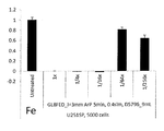
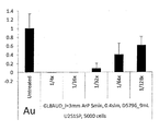
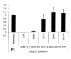
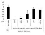
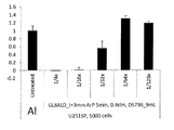
まず、それぞれのデータについてサンプル数(N数)を1として実験したデータを示す。図6は、第2の電極210の先端部211としてAuを用いた場合の抗腫瘍水溶液の抗腫瘍効果を示すグラフ(N=1)である。図7は、第2の電極210の先端部211としてPtを用いた場合の抗腫瘍水溶液の抗腫瘍効果を示すグラフ(N=1)である。図8は、第2の電極210の先端部211としてNiを用いた場合の抗腫瘍水溶液の抗腫瘍効果を示すグラフ(N=1)である。図9は、第2の電極210の先端部211としてAlを用いた場合の抗腫瘍水溶液の抗腫瘍効果を示すグラフ(N=1)である。図10は、第2の電極210の先端部211としてCuを用いた場合の抗腫瘍水溶液の抗腫瘍効果を示すグラフ(N=1)である。図11は、第2の電極210の先端部211としてFeを用いた場合の抗腫瘍水溶液の抗腫瘍効果を示すグラフ(N=1)である。
まず、それぞれのデータについてサンプル数(N数)を1として実験したデータを示す。図6は、第2の電極210の先端部211としてAuを用いた場合の抗腫瘍水溶液の抗腫瘍効果を示すグラフ(N=1)である。図7は、第2の電極210の先端部211としてPtを用いた場合の抗腫瘍水溶液の抗腫瘍効果を示すグラフ(N=1)である。図8は、第2の電極210の先端部211としてNiを用いた場合の抗腫瘍水溶液の抗腫瘍効果を示すグラフ(N=1)である。図9は、第2の電極210の先端部211としてAlを用いた場合の抗腫瘍水溶液の抗腫瘍効果を示すグラフ(N=1)である。図10は、第2の電極210の先端部211としてCuを用いた場合の抗腫瘍水溶液の抗腫瘍効果を示すグラフ(N=1)である。図11は、第2の電極210の先端部211としてFeを用いた場合の抗腫瘍水溶液の抗腫瘍効果を示すグラフ(N=1)である。
図6から図11に示すように、第2の電極210の先端部211としていずれの材料を用いても、16倍以下に希釈した抗腫瘍水溶液は高い抗腫瘍効果を示した。つまり、これらの抗腫瘍水溶液を用いた場合には、グリオーマの生存率はほぼゼロであった。また、64倍に希釈した抗腫瘍水溶液については、Auを用いた場合にグリオーマの生存率は40%程度であった。64倍に希釈した抗腫瘍水溶液については、Pt、Ni、Feを用いた場合にグリオーマの生存率は80%程度であった。64倍に希釈した抗腫瘍水溶液については、Al、Cuを用いた場合にグリオーマの生存率は100%程度であった。したがって、抗腫瘍効果の強さを鑑みると、第2の電極210の先端部211としてAuを用いることが最も好ましい。
次に、それぞれのデータについてサンプル数(N数)を4として実験したデータを示す。図12は、第2の電極210の先端部211としてAuを用いた場合の抗腫瘍水溶液の抗腫瘍効果を示すグラフ(N=4)である。図13は、第2の電極210の先端部211としてPtを用いた場合の抗腫瘍水溶液の抗腫瘍効果を示すグラフ(N=4)である。図14は、第2の電極210の先端部211としてNiを用いた場合の抗腫瘍水溶液の抗腫瘍効果を示すグラフ(N=4)である。図15は、第2の電極210の先端部211としてAlを用いた場合の抗腫瘍水溶液の抗腫瘍効果を示すグラフ(N=4)である。図16は、第2の電極210の先端部211としてCuを用いた場合の抗腫瘍水溶液の抗腫瘍効果を示すグラフ(N=4)である。図17は、第2の電極210の先端部211としてFeを用いた場合の抗腫瘍水溶液の抗腫瘍効果を示すグラフ(N=4)である。
この場合には、サンプル数(N数)が4であるため、第2の電極210の先端部211の耐久性を調べたこととなる。16倍に希釈した抗腫瘍水溶液については、Au、Pt、Ni、Alを用いた場合には、グリオーマの生存率はほぼゼロであった。また、16倍に希釈した抗腫瘍水溶液については、Cu、Feを用いた場合には、グリオーマの生存率は80%程度であった。また、8倍に希釈した抗腫瘍水溶液については、Au、Pt、Ni、Al、Cuを用いた場合には、グリオーマの生存率はほぼゼロであった。8倍に希釈した抗腫瘍水溶液については、Feを用いた場合には、グリオーマの生存率は80%程度であった。このように、第2の電極210の先端部211としてCu、Feを用いた場合には、放電を繰り返すことにより、製造される抗腫瘍水溶液の抗腫瘍効果は低下した。つまり、Au、Pt、Ni、Alは、Cu、Feに比べて耐久性に優れている。
7-3.実験結果(腐食)
図18は、第2の電極210の先端部211としてAuを用いた場合の第2電極210を示す写真である。図19は、第2の電極210の先端部211としてPtを用いた場合の第2電極210を示す写真である。図20は、第2の電極210の先端部211としてNiを用いた場合の第2電極210を示す写真である。図21は、第2の電極210の先端部211としてAlを用いた場合の第2電極210を示す写真である。図22は、第2の電極210の先端部211としてCuを用いた場合の第2電極210を示す写真である。図23は、第2の電極210の先端部211としてFeを用いた場合の第2電極210を示す写真である。
図18は、第2の電極210の先端部211としてAuを用いた場合の第2電極210を示す写真である。図19は、第2の電極210の先端部211としてPtを用いた場合の第2電極210を示す写真である。図20は、第2の電極210の先端部211としてNiを用いた場合の第2電極210を示す写真である。図21は、第2の電極210の先端部211としてAlを用いた場合の第2電極210を示す写真である。図22は、第2の電極210の先端部211としてCuを用いた場合の第2電極210を示す写真である。図23は、第2の電極210の先端部211としてFeを用いた場合の第2電極210を示す写真である。
図18から図23の写真を観察したところ、Al、Cu、Feについては、電極の腐食が見られた。そのため、Au、Pt、Niは、Al、Cu、Feに比べて腐食しにくい。
以上より、第2の電極210の先端部211としてAuが最も適している。Auを用いて製造した抗腫瘍水溶液の抗腫瘍効果は高く、Auは腐食しにくいからである。次に、Pt、Niが好ましい。Al、Cu、Feは、Au、Pt、Niに比べて腐食しやすいが、第2の電極210の先端部211として適用することができないわけではない。
7-4.考察
ここで、Au、Pt、Niの仕事関数は5eV以上である。Al、Cu、Feの仕事関数は4.5eV程度である。Auのように仕事関数の高い金属では、プラズマを維持するために電子の供給が不可欠である。本実施形態では、第2の電極210の先端部211の表面にエネルギーの高い荷電粒子が衝突し、先端部211の内部の電子を励起して放出するというプロセスをたどる。荷電粒子は、先端部211の付近の電圧降下部により加速される。Auのように仕事関数の高い金属では、より急勾配な電圧降下部が形成される。したがって、仕事関数の高い金属において、プラズマ生成物がより効率的に生成されると考えられる。
ここで、Au、Pt、Niの仕事関数は5eV以上である。Al、Cu、Feの仕事関数は4.5eV程度である。Auのように仕事関数の高い金属では、プラズマを維持するために電子の供給が不可欠である。本実施形態では、第2の電極210の先端部211の表面にエネルギーの高い荷電粒子が衝突し、先端部211の内部の電子を励起して放出するというプロセスをたどる。荷電粒子は、先端部211の付近の電圧降下部により加速される。Auのように仕事関数の高い金属では、より急勾配な電圧降下部が形成される。したがって、仕事関数の高い金属において、プラズマ生成物がより効率的に生成されると考えられる。
8.変形例
8-1.用途
本実施形態では、プラズマ発生装置1000について、プラズマを培養液に照射する用途について適用した。しかし、プラズマ発生装置1000については、その他の液体に高密度のプラズマを照射する場合にも用いることができる。つまり、抗腫瘍水溶液を製造する用途以外に用いてももちろん構わない。
8-1.用途
本実施形態では、プラズマ発生装置1000について、プラズマを培養液に照射する用途について適用した。しかし、プラズマ発生装置1000については、その他の液体に高密度のプラズマを照射する場合にも用いることができる。つまり、抗腫瘍水溶液を製造する用途以外に用いてももちろん構わない。
8-2.第1電極
本実施形態のプラズマ発生装置1000では、第1電極110の筒形状部110aは、円筒形状である。しかし、円筒形状に限らない。筒形状であれば、多角形形状であってもよい。
本実施形態のプラズマ発生装置1000では、第1電極110の筒形状部110aは、円筒形状である。しかし、円筒形状に限らない。筒形状であれば、多角形形状であってもよい。
9.本実施形態のまとめ
以上詳細に説明したように、本実施形態のプラズマ発生装置1000は、円筒形状の第1電極110と、液面を挟んで第1電極110と対向する棒状の第2電極210と、を有している。また、第1電極110の先端部111は、第1電極110の軸方向に垂直な面に対して傾斜する傾斜面111aと、マイクロホロー111bと、を有している。そのため、このプラズマ発生装置1000は、高密度のプラズマを発生させることができる。このプラズマ発生装置1000は、正常細胞にほとんど影響を与えることなく癌細胞を死滅させることのできる抗腫瘍水溶液の製造に好適である。
以上詳細に説明したように、本実施形態のプラズマ発生装置1000は、円筒形状の第1電極110と、液面を挟んで第1電極110と対向する棒状の第2電極210と、を有している。また、第1電極110の先端部111は、第1電極110の軸方向に垂直な面に対して傾斜する傾斜面111aと、マイクロホロー111bと、を有している。そのため、このプラズマ発生装置1000は、高密度のプラズマを発生させることができる。このプラズマ発生装置1000は、正常細胞にほとんど影響を与えることなく癌細胞を死滅させることのできる抗腫瘍水溶液の製造に好適である。
1000…プラズマ発生装置
110…第1電極
120…第1の電位付与部
130…第1のリード線
140…ガス供給部
150…ガス管結合コネクター
160…ガス管
170…第1電極保護部材
210…第2電極
220…第2の電位付与部
230…第2のリード線
240…第2電極保護部材
250…容器
260…封止部材
270…架台
110…第1電極
120…第1の電位付与部
130…第1のリード線
140…ガス供給部
150…ガス管結合コネクター
160…ガス管
170…第1電極保護部材
210…第2電極
220…第2の電位付与部
230…第2のリード線
240…第2電極保護部材
250…容器
260…封止部材
270…架台
Claims (8)
- 筒形状部を備える第1電極と、
前記第1電極と対向する第2電極と、
前記第1電極の前記筒形状部の内部にガスを供給するガス供給部と、
を有し、
前記第1電極は、
前記筒形状部から前記第2電極に向けてガスを流すこと
を特徴とするプラズマ発生装置。 - 請求項1に記載のプラズマ発生装置において、
前記第1電極と前記第2電極とを収容するとともに液体を収容する容器と、
前記第1電極と前記第2電極との間に電圧を印加する電圧印加部と、
を有し、
前記電圧印加部が、前記第1電極と前記第2電極との間に電圧を印加する電圧印加時には、
前記第2電極は、
液体の内部に配置されていること
を特徴とするプラズマ発生装置。 - 請求項2に記載のプラズマ発生装置において、
前記第1電極と前記第2電極とを結ぶ線が、
液体の液面と交差しており、
前記第1電極から流れるガスが、
液体の液面を凹ませること
を特徴とするプラズマ発生装置。 - 請求項1から請求項3までのいずれか1項に記載のプラズマ発生装置において、
前記第2の電極は、
棒状電極であること
を特徴とするプラズマ発生装置。 - 請求項4に記載のプラズマ発生装置において、
前記棒状電極の先端は、
Au、Pt、Ni、Al、Cu、Feのうちの少なくとも一種類以上を含む金属もしくは合金であること
を特徴とするプラズマ発生装置。 - 請求項1から請求項5までのいずれか1項に記載のプラズマ発生装置において、
前記第1の電極は、
先端部を有し、
前記先端部は、
前記第1電極の軸方向に垂直な面に対して傾斜する傾斜面を有すること
を特徴とするプラズマ発生装置。 - 請求項6に記載のプラズマ発生装置において、
前記先端部は、
マイクロホローを有すること
を特徴とするプラズマ発生装置。 - 抗腫瘍水溶液の製造方法において、
リン酸水素二ナトリウム(Na2 HPO4 )と、炭酸水素ナトリウム(NaHCO3 )と、L-グルタミン(L-Glutamine)と、L-ヒスチジン(L-Histidine)と、L-チロシン二ナトリウム二水和物(L-Tyrosine・2Na・2H2 O)とのうちの少なくとも1種類を含む溶質を水に添加した第1の水溶液を準備する水溶液準備工程と、
前記第1の水溶液にプラズマを照射するプラズマ照射工程と、
を有し、
前記プラズマ照射工程では、
第1電極を前記第1の水溶液の外に配置するとともに第2電極を前記第1の水溶液の中に配置し、
前記第1電極から前記第1の水溶液に向かってガスを照射し、
その状態で前記第1電極と前記第2電極との間に電圧を印加すること
を特徴とする抗腫瘍水溶液の製造方法。
Priority Applications (1)
| Application Number | Priority Date | Filing Date | Title |
|---|---|---|---|
| JP2016517578A JP6755491B2 (ja) | 2014-09-04 | 2015-09-02 | 抗腫瘍水溶液の製造方法 |
Applications Claiming Priority (2)
| Application Number | Priority Date | Filing Date | Title |
|---|---|---|---|
| JP2014-180463 | 2014-09-04 | ||
| JP2014180463 | 2014-09-04 |
Publications (1)
| Publication Number | Publication Date |
|---|---|
| WO2016035339A1 true WO2016035339A1 (ja) | 2016-03-10 |
Family
ID=55439418
Family Applications (1)
| Application Number | Title | Priority Date | Filing Date |
|---|---|---|---|
| PCT/JP2015/004467 Ceased WO2016035339A1 (ja) | 2014-09-04 | 2015-09-02 | プラズマ発生装置および抗腫瘍水溶液の製造方法 |
Country Status (2)
| Country | Link |
|---|---|
| JP (1) | JP6755491B2 (ja) |
| WO (1) | WO2016035339A1 (ja) |
Cited By (3)
| Publication number | Priority date | Publication date | Assignee | Title |
|---|---|---|---|---|
| EP3488867A4 (en) * | 2016-07-19 | 2020-04-01 | Fuji Corporation | DEVICE FOR PRODUCING AN ANTITUMORAL AQUEOUS SOLUTION |
| JP6916362B1 (ja) * | 2020-10-13 | 2021-08-11 | 積水化学工業株式会社 | 保持部材、照射器具及びプラズマ装置 |
| CN116589041A (zh) * | 2023-03-31 | 2023-08-15 | 华中科技大学 | 一种基于水帘等离子体的活化水制备装置及方法 |
Citations (4)
| Publication number | Priority date | Publication date | Assignee | Title |
|---|---|---|---|---|
| JP2005296909A (ja) * | 2004-03-16 | 2005-10-27 | Toshiba Corp | 水処理システム |
| WO2012157248A1 (ja) * | 2011-05-17 | 2012-11-22 | パナソニック株式会社 | プラズマ発生装置およびプラズマ発生方法 |
| WO2013128905A1 (ja) * | 2012-02-27 | 2013-09-06 | 国立大学法人名古屋大学 | 抗腫瘍水溶液および抗癌剤とそれらの製造方法 |
| JP2013211153A (ja) * | 2012-03-30 | 2013-10-10 | Nagoya Univ | プラズマ発生装置 |
Family Cites Families (3)
| Publication number | Priority date | Publication date | Assignee | Title |
|---|---|---|---|---|
| JP4191885B2 (ja) * | 2000-06-29 | 2008-12-03 | 三菱重工環境エンジニアリング株式会社 | プラズマ式灰溶融炉及びその運転方法 |
| JP2007306947A (ja) * | 2006-02-23 | 2007-11-29 | Sutai Rabo:Kk | アスベストの無害化処理方法およびプラズマ放電処理水生成装置 |
| JP5909831B2 (ja) * | 2012-12-30 | 2016-04-27 | 株式会社 東北テクノアーチ | 病原菌および害虫の駆除装置 |
-
2015
- 2015-09-02 JP JP2016517578A patent/JP6755491B2/ja active Active
- 2015-09-02 WO PCT/JP2015/004467 patent/WO2016035339A1/ja not_active Ceased
Patent Citations (4)
| Publication number | Priority date | Publication date | Assignee | Title |
|---|---|---|---|---|
| JP2005296909A (ja) * | 2004-03-16 | 2005-10-27 | Toshiba Corp | 水処理システム |
| WO2012157248A1 (ja) * | 2011-05-17 | 2012-11-22 | パナソニック株式会社 | プラズマ発生装置およびプラズマ発生方法 |
| WO2013128905A1 (ja) * | 2012-02-27 | 2013-09-06 | 国立大学法人名古屋大学 | 抗腫瘍水溶液および抗癌剤とそれらの製造方法 |
| JP2013211153A (ja) * | 2012-03-30 | 2013-10-10 | Nagoya Univ | プラズマ発生装置 |
Cited By (4)
| Publication number | Priority date | Publication date | Assignee | Title |
|---|---|---|---|---|
| EP3488867A4 (en) * | 2016-07-19 | 2020-04-01 | Fuji Corporation | DEVICE FOR PRODUCING AN ANTITUMORAL AQUEOUS SOLUTION |
| JP6916362B1 (ja) * | 2020-10-13 | 2021-08-11 | 積水化学工業株式会社 | 保持部材、照射器具及びプラズマ装置 |
| CN116589041A (zh) * | 2023-03-31 | 2023-08-15 | 华中科技大学 | 一种基于水帘等离子体的活化水制备装置及方法 |
| CN116589041B (zh) * | 2023-03-31 | 2025-09-05 | 华中科技大学 | 一种基于水帘等离子体的活化水制备装置及方法 |
Also Published As
| Publication number | Publication date |
|---|---|
| JPWO2016035339A1 (ja) | 2017-06-22 |
| JP6755491B2 (ja) | 2020-09-16 |
Similar Documents
| Publication | Publication Date | Title |
|---|---|---|
| JP6099277B2 (ja) | 抗腫瘍水溶液および抗癌剤とそれらの製造方法 | |
| CN103889903B (zh) | 液体处理装置以及液体处理方法 | |
| JP6306604B2 (ja) | 歯インプラント部のための治療要素及び当該治療要素を用いた治療システム | |
| JP5821020B2 (ja) | 液体処理装置及び液体処理方法 | |
| JP6605797B2 (ja) | 流体中プラズマ発生方法及び流体中プラズマ発生装置 | |
| JP5979350B2 (ja) | プラズマ発生装置 | |
| JP2014167913A (ja) | 生体膜の処理のためのシステムおよび方法 | |
| JP6736004B2 (ja) | 抗癌剤および輸液とそれらの製造方法ならびに抗癌物質 | |
| JP6755491B2 (ja) | 抗腫瘍水溶液の製造方法 | |
| CN107106859A (zh) | 等离子体治疗感染的指甲或感染的皮肤 | |
| JP2016513145A (ja) | インプラント部品洗浄用治療液 | |
| JP2008183502A (ja) | ナノバブルによる水処理装置及びナノバブルによる水処理方法 | |
| JP2018202382A (ja) | 液体処理装置 | |
| CN105271475A (zh) | 处理液生成装置及处理液生成方法 | |
| JP2015026574A (ja) | プラズマ生成装置 | |
| RU2670654C9 (ru) | Способ получения дезинфицирующего агента и устройство для его осуществления | |
| Belov et al. | A device for biological activation of aqueous solutions using glow discharge plasma in water vapor | |
| JP6381111B2 (ja) | 抗腫瘍水溶液および抗癌剤とそれらの製造方法 | |
| Han | Review of major directions in non-equilibrium atmospheric plasma treatments in medical, biological, and bioengineering applications | |
| KR200343752Y1 (ko) | 연속식 은 콜로이드 수용액 제조장치와 이를 이용한 살균가습기 | |
| JP7040770B2 (ja) | 活性種含有液噴射装置 | |
| JP2016093770A (ja) | 水素水の生成方法及び水素水の生成装置 | |
| JP2016169164A (ja) | 抗腫瘍水溶液とその製造方法 | |
| JP7154524B2 (ja) | 腹腔内洗浄溶液の製造方法 | |
| JP7097543B2 (ja) | イネの生産方法 |
Legal Events
| Date | Code | Title | Description |
|---|---|---|---|
| ENP | Entry into the national phase |
Ref document number: 2016517578 Country of ref document: JP Kind code of ref document: A |
|
| 121 | Ep: the epo has been informed by wipo that ep was designated in this application |
Ref document number: 15837317 Country of ref document: EP Kind code of ref document: A1 |
|
| NENP | Non-entry into the national phase |
Ref country code: DE |
|
| 122 | Ep: pct application non-entry in european phase |
Ref document number: 15837317 Country of ref document: EP Kind code of ref document: A1 |