WO2016031348A1 - 脳機能障害評価システム、脳機能障害評価方法およびプログラム - Google Patents
脳機能障害評価システム、脳機能障害評価方法およびプログラム Download PDFInfo
- Publication number
- WO2016031348A1 WO2016031348A1 PCT/JP2015/066997 JP2015066997W WO2016031348A1 WO 2016031348 A1 WO2016031348 A1 WO 2016031348A1 JP 2015066997 W JP2015066997 W JP 2015066997W WO 2016031348 A1 WO2016031348 A1 WO 2016031348A1
- Authority
- WO
- WIPO (PCT)
- Prior art keywords
- hands
- difference
- hand
- waveform
- time
- Prior art date
Links
Images


Classifications
-
- A—HUMAN NECESSITIES
- A61—MEDICAL OR VETERINARY SCIENCE; HYGIENE
- A61B—DIAGNOSIS; SURGERY; IDENTIFICATION
- A61B5/00—Measuring for diagnostic purposes; Identification of persons
- A61B5/103—Detecting, measuring or recording devices for testing the shape, pattern, colour, size or movement of the body or parts thereof, for diagnostic purposes
- A61B5/11—Measuring movement of the entire body or parts thereof, e.g. head or hand tremor, mobility of a limb
- A61B5/1124—Determining motor skills
-
- A—HUMAN NECESSITIES
- A61—MEDICAL OR VETERINARY SCIENCE; HYGIENE
- A61B—DIAGNOSIS; SURGERY; IDENTIFICATION
- A61B5/00—Measuring for diagnostic purposes; Identification of persons
- A61B5/0002—Remote monitoring of patients using telemetry, e.g. transmission of vital signals via a communication network
- A61B5/0015—Remote monitoring of patients using telemetry, e.g. transmission of vital signals via a communication network characterised by features of the telemetry system
- A61B5/0022—Monitoring a patient using a global network, e.g. telephone networks, internet
-
- A—HUMAN NECESSITIES
- A61—MEDICAL OR VETERINARY SCIENCE; HYGIENE
- A61B—DIAGNOSIS; SURGERY; IDENTIFICATION
- A61B5/00—Measuring for diagnostic purposes; Identification of persons
- A61B5/103—Detecting, measuring or recording devices for testing the shape, pattern, colour, size or movement of the body or parts thereof, for diagnostic purposes
- A61B5/11—Measuring movement of the entire body or parts thereof, e.g. head or hand tremor, mobility of a limb
-
- A—HUMAN NECESSITIES
- A61—MEDICAL OR VETERINARY SCIENCE; HYGIENE
- A61B—DIAGNOSIS; SURGERY; IDENTIFICATION
- A61B5/00—Measuring for diagnostic purposes; Identification of persons
- A61B5/40—Detecting, measuring or recording for evaluating the nervous system
- A61B5/4076—Diagnosing or monitoring particular conditions of the nervous system
- A61B5/4088—Diagnosing of monitoring cognitive diseases, e.g. Alzheimer, prion diseases or dementia
-
- A—HUMAN NECESSITIES
- A61—MEDICAL OR VETERINARY SCIENCE; HYGIENE
- A61B—DIAGNOSIS; SURGERY; IDENTIFICATION
- A61B5/00—Measuring for diagnostic purposes; Identification of persons
- A61B5/68—Arrangements of detecting, measuring or recording means, e.g. sensors, in relation to patient
- A61B5/6801—Arrangements of detecting, measuring or recording means, e.g. sensors, in relation to patient specially adapted to be attached to or worn on the body surface
- A61B5/6813—Specially adapted to be attached to a specific body part
- A61B5/6825—Hand
- A61B5/6826—Finger
-
- A—HUMAN NECESSITIES
- A61—MEDICAL OR VETERINARY SCIENCE; HYGIENE
- A61B—DIAGNOSIS; SURGERY; IDENTIFICATION
- A61B5/00—Measuring for diagnostic purposes; Identification of persons
- A61B5/72—Signal processing specially adapted for physiological signals or for diagnostic purposes
- A61B5/7235—Details of waveform analysis
- A61B5/7253—Details of waveform analysis characterised by using transforms
- A61B5/7257—Details of waveform analysis characterised by using transforms using Fourier transforms
-
- A—HUMAN NECESSITIES
- A61—MEDICAL OR VETERINARY SCIENCE; HYGIENE
- A61B—DIAGNOSIS; SURGERY; IDENTIFICATION
- A61B2562/00—Details of sensors; Constructional details of sensor housings or probes; Accessories for sensors
- A61B2562/02—Details of sensors specially adapted for in-vivo measurements
- A61B2562/0257—Proximity sensors
Definitions
- the present invention relates to a technique for evaluating the degree of brain dysfunction including cognitive decline.
- dementia memory impairment, disorientation, learning disabilities, etc. occur, which greatly impairs daily life. There may also be problematic behaviors such as rants, violence, obscenity and filthy behavior. In addition, at the end of dementia, movement disorders such as small gait and leaning forward appear, eventually falling into a bedridden state.
- dementia There are three major types of dementia: Alzheimer's dementia, cerebrovascular dementia, and Lewy body dementia.
- cognitive function may be reduced in addition to movement disorders such as Parkinson's disease and mental disorders such as depression and schizophrenia.
- appropriate treatment such as pharmacotherapy can be performed. Any type of dementia can be detected at an early stage, and the appropriate drug can be administered to suppress progression in a mild state. For these reasons, screening tests for early detection of dementia are necessary for healthy elderly people who are likely to have dementia.
- the mainstream of diagnosis of dementia is examination of cognitive functions such as memory and judgment, such as the Hasegawa scale and MMSE (Mini Mental State Examination).
- these diagnosis methods are performed by doctors over several minutes to several tens of minutes, and are not suitable for screening tests for a large number of subjects from the viewpoint of time constraints.
- a method of examining the presence or absence of brain atrophy using CT (Computed Tomography) and MRI (Magnetic Resonance Imaging), SPECT (Single Photon Emission Computed Tomography), and PET (Positron Emission Tomography) Diagnosis by brain image measurement such as a method for examining the accumulation status of amyloid beta is also performed.
- CT Computer Tomography
- MRI Magnetic Resonance Imaging
- SPECT Single Photon Emission Computed Tomography
- PET PET
- Patent Document 1 Patent Document 2, Patent Document 3, Non-Patent Document 1, and the like use a device that can easily measure finger movement, such as a button press device, a tablet computer, or a magnetic sensor.
- Patent Document 4 proposes a method of expressing cognitive function deterioration by evaluating a phase difference in finger tapping movements of both hands (opening / closing movements of two fingers (such as a thumb and an index finger) repeatedly).
- Patent Document 1 Since it is said that the difference in motor function between both hands increases as the cognitive function declines, the method of calculating the difference in motor function between both hands is effective. From this point of view, the techniques of Patent Document 1, Patent Document 2, Patent Document 3, and Non-Patent Document 1 measure the finger movement of one hand, and thus cannot evaluate the difference in the motor function of both hands. Further, Patent Document 4 proposes a method for evaluating a phase difference in finger tapping motion of both hands, but does not meet the above purpose because a difference in motor functions of both hands is not explicitly calculated.
- an object of the present invention is to easily evaluate the degree of cerebral dysfunction including cognitive decline by calculating the difference in the motor functions of both hands in the two-hand cooperative movement.
- the present invention provides a storage means for storing time series data relating to each movement of both hands of a subject acquired from a motion sensor, and an analysis means for analyzing the time series data stored in the storage means. And a display means for displaying the analysis result analyzed by the analysis means, wherein the analysis means is based on the time-series data stored in the storage means, A motion waveform generation means for generating a motion waveform corresponding to time-series data, and a two-hand difference feature amount generation that generates a difference between both hands based on the motion waveform of each of the subject's hands.
- a cerebral dysfunction evaluation system comprising: means. Other means will be described later.
- the present invention it is possible to easily evaluate the degree of cerebral dysfunction including cognitive decline by calculating the difference in the motor function of both hands in the two-hand cooperative movement.
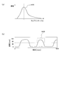
- (A) is explanatory drawing of the skewness of the frequency distribution of a tap interval.
- (B) is explanatory drawing of the kurtosis near the maximum point in a distance waveform. It is explanatory drawing of the locus
- (A) is the figure which showed the locus
- (B) is the figure which showed the locus
- (A) is the figure which showed the time of both hands simultaneous finger tap.
- (B) is the figure which showed the time of both-hands alternating finger tap.
- (A) is explanatory drawing of the fluctuation
- (B) is explanatory drawing of the frequency peak of a both-hands differential waveform. It is the figure which showed the subject information input screen. It is the figure which showed the measurement screen. It is a block diagram when this invention is comprised with a terminal device and a server apparatus.
- cerebral dysfunction generally refers to those that develop so-called cognitive decline (Alzheimer type dementia, cerebrovascular dementia, Lewy body dementia, Parkinson's disease, hydrocephalus, Depression, schizophrenia, etc.) generically, but includes movement disorders such as stroke.
- cognitive decline Alzheimer's disease, cerebrovascular dementia, Lewy body dementia, Parkinson's disease, hydrocephalus, Depression, schizophrenia, etc.
- the brain dysfunction may be simply referred to as dementia.
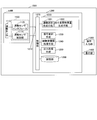
- the cerebral dysfunction evaluation system 1000 records and analyzes a motor function measuring device 1100 that measures the finger movement of a subject and data measured by the motor function measuring device 1100.
- a cerebral dysfunction evaluation apparatus 1200 an operation input unit 1300 for inputting subject information and the like, and a display unit 1400 (display means) for outputting measurement results and analysis results and displaying the output data Is done.
- the test subject is a measurement target by the motor function measuring apparatus 1100, and in this embodiment, is a person who desires a test for the presence or absence or severity of dementia.
- the motor function measuring apparatus 1100 measures the movement of the finger when the subject performs a finger motion.
- finger movement refers to finger tapping movement (movement that opens and closes the thumb and forefinger of the hand as fast and as large as possible) or a touch panel sensor (screen contact sensor) measured by a magnetic sensor. This includes the exercise of touching and sliding on the screen of a tablet terminal or the like.
- the finger movement is a finger tapping movement.
- the motor function measuring apparatus 1100 detects information on finger movements of the subject (hereinafter, also simply referred to as “motion information”) in time series, and includes at least distance, speed, acceleration, and jerk (acceleration in time).
- the motion information of the subject regarding any one of the differentiated ones) is acquired as time-series data (waveform data).
- the motor function measuring device 1100 includes a motor sensor 1110, a motor sensor interface 1120, and a motor sensor control unit 1130.
- the motion sensor interface 1120 and the motion sensor control unit 1130 are housed in a housing unit 1500 that is one housing. In addition, it is not necessary to put in one housing.
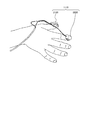
- the motion sensor 1110 includes a transmission coil 2100 that transmits a magnetic field and a reception coil 2200 that receives (detects) this magnetic field.
- the transmitting coil 2100 is attached to the nail portion of the thumb, and the receiving coil 2200 is attached to the nail portion of the index finger, for example, with double-sided tape or the like. Note that the transmitting coil 2100 may be attached to the nail portion of the index finger and the receiving coil 2200 may be attached to the nail portion of the thumb.
- part of the transmission coil 2100 and the receiving coil 2200 is demonstrated as a nail
- the present invention is not limited to the thumb and the index finger, and may be attached to another combination of fingers such as the thumb and the little finger.
- the wearing part is not limited to the nail part or finger of the subject, but also includes a peripheral part such as a palm close to the finger. Therefore, as long as finger movements can be detected, the wearing portions of the transmission coil 2100 and the reception coil 2200 may be any of the subject's nails, fingers, and peripheral portions of the fingers.
- the motion sensor interface 1120 (see FIG. 1) includes an analog / digital conversion circuit.
- the analog sensor waveform data detected by the motion sensor 1110 is converted into digital signal waveform data at a predetermined sampling frequency.
- the digital signal is introduced into the motion sensor control unit 1130 (see FIG. 1).
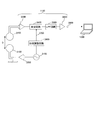
- FIG. 3 is a block diagram showing a configuration and the like of the motion sensor control unit 1130 (the motion sensor interface 1120 is not shown). Here, the procedure by which the motion sensor control unit 1130 acquires waveform data will be described.
- an AC voltage having a specific frequency (for example, 20 kHz) is created by the AC generation circuit 3100.
- the AC voltage having a specific frequency created by the AC generation circuit 3100 is converted into an AC current having a specific frequency by the current generation amplifier circuit 3200, and the converted AC current flows through the transmission coil 2100.
- the magnetic field generated by the alternating current flowing through the transmission coil 2100 causes the reception coil 2200 to generate an induced electromotive force.
- the alternating current generated in the receiving coil 2200 by the induced electromotive force (having the same frequency as the alternating voltage having a specific frequency created by the alternating current generating circuit 3100) is amplified by the preamplifier circuit 3300, and is amplified.
- the signal is input to the detection circuit 3400.
- the detection circuit 3400 detects the amplified signal using the specific frequency or double frequency generated by the AC generation circuit 3100. That is, the fluctuation of the voltage accompanying the change in the distance between fingers is extracted from the waveform including the high frequency. Therefore, the phase of the output of the AC generation circuit 3100 is adjusted by the phase adjustment circuit 3600 and then introduced as a reference signal 3700 to the reference signal input terminal of the detection circuit 3400.
- the output signal of the detection circuit 3400 passes through an LPF (Low-Pass Filter) circuit 3500 for removing high-frequency components, and then is amplified by the amplifier circuit 3800 to obtain a desired voltage, and is supplied to the brain dysfunction evaluation apparatus 1200. be introduced.
- the output signal 3900 of the amplifier circuit 3800 represents a voltage value corresponding to the relative distance D between the transmitting coil 2100 and the receiving coil 2200 respectively attached to the thumb and the index finger (the conversion formula between the relative distance and the voltage value will be described later).
- a magnetic sensor is used as the motion sensor 1110
- an acceleration sensor a strain gauge, a high-speed camera, or the like
- finger movement may be measured by touching or sliding one or more fingers on a screen of a tablet terminal or a smartphone.
- the brain dysfunction evaluation apparatus 1200 records and analyzes data measured by the motor function measurement apparatus 1100.
- the brain dysfunction evaluation apparatus 1200 includes a data input unit 1210 that inputs an output signal (time-series data) from the motion sensor control unit 1130, and a data processing unit 1220 that analyzes the input output signal (analysis means). And a signal control means 1230 for transmitting a signal for starting measurement to the motor function measuring device 1100, a subject information processing means 1240, and an output for processing the analysis results of the data processing section 1220 into a format that can be output to the display section 1400.
- the data processing unit 1220 calculates (generates) a motion waveform of the finger tapping motion of the subject based on the output signal sent from the data input unit 1210 and obtained through the control unit 1270, and the dementia Calculate objective indicators of severity. Each information is appropriately stored in the storage unit 1260.
- the data processing unit 1220 includes an exercise waveform generation unit 1221 and a two-hand difference feature amount generation unit 1222.
- the motion waveform generation means 1221 converts the time series data (waveform data) of the voltage output sent from the motor function measuring device 1100 into a corresponding motion waveform, and time-differentiates the converted motion waveform.
- the distance waveform, the velocity waveform, and the acceleration waveform are complementarily generated by time integration (details will be described later).
- the conversion formula for converting the voltage output (voltage value) into a motion waveform is, for example, a plurality of blocks having different lengths (for example, blocks having a length of 20, 30, 60 mm).
- a motion waveform such as a relative distance waveform
- FIG. 4 is obtained by time-differentiating the distance waveform 4100 obtained by converting the waveform data using a conversion formula, the velocity waveform 4200 obtained by time-differentiating the distance waveform 4100, and the velocity waveform 4200. It is a figure which shows the acceleration waveform 4300.
- the “movement waveform” includes at least one of a distance waveform, a velocity waveform, an acceleration waveform, and a jerk waveform unless otherwise specified. Further, even when a strain gauge, an accelerometer, or the like is applied as the motor function measuring device 1100, if at least one motor waveform is measured, another motor waveform (distance, Speed, acceleration, jerk).
- the two-hand difference feature quantity generating unit 1222 (see FIG. 1) generates a two-hand difference feature quantity that represents a difference in finger movement between both hands from the exercise waveform obtained from the exercise waveform generation unit 1221.
- the first is a method (first two-hand difference feature value calculation method) in which a feature value is calculated individually from the motion waveforms of the right hand and left hand and then the difference between the two feature values is calculated.
- the second method is a method (second two-hand difference feature amount calculation method) of calculating feature values for the difference waveform after calculating time-series data that is the difference between the right hand and left hand motion waveforms.
- FIG. 5 is a diagram showing the names and definitions of feature quantities.
- the feature amounts of feature amount numbers 5023 to 5029 will be described in detail. Note that the feature amounts of the feature amount numbers 5001 to 5022 are as defined in FIG. 5, and thus detailed description thereof is omitted.
- “feature value of feature quantity number 50 **” is also expressed as “feature quantity 50 **”.
- the period 6100 of the finger tapping motion is the same as the next condition when the distance value intersects the average value 6200 during the measurement time of the distance waveform and the speed becomes less than zero.
- the tap interval is the length of one cycle.
- a point where the distance value is minimum within one period is set as a minimum point 6300 of the distance waveform, and the distance value at that time is set as a minimum value.
- the point where the distance value is maximum in one cycle is set as the local maximum point 6400 of the distance waveform, and the distance value at that time is set as the local maximum value.
- the opening operation 6500 is defined as the distance waveform from the minimum point to the next maximum point
- the closing operation 6600 is defined as the distance waveform from the maximum point to the next minimum point.
- the number of zero crossings 5023 of the velocity waveform (feature amount 5023. The following may also be described in the same manner) (see FIG. 5) refers to the number of times the velocity has changed from a positive value to a negative value during the measurement time. The value obtained by subtracting the number of times of tapping 5019. The number of times that the speed has changed from a positive value to a negative value may be the number of times that the speed has changed from a negative value to a positive value.
- the number of zero crossings 5023 in the velocity waveform is a feature amount for counting the number of fine vertical movements 7100 other than the large finger tapping movement shown in the distance waveform as shown in FIG.
- the number of times the velocity waveform crosses zero corresponds to the number of fine vertical movements of the distance waveform.
- the number of such vertical movements with a fine distance waveform is greater in patients with dementia than in healthy individuals.
- the number of acceleration waveform zero crossings 5024 is a value obtained by subtracting the number of tappings 5019 from the number of times the acceleration has changed from a positive value to a negative value during the measurement time.
- the number of times that the acceleration has changed from a positive value to a negative value may be the number of times that the acceleration has changed from a negative value to a positive value.
- the number of zero crossings 5024 in the acceleration waveform is not limited to a fine vertical movement, but is a feature amount for counting the number of times portion 7200 where the strength of the momentum changes unnaturally during the finger tapping movement. It is.
- the number of times that the acceleration waveform crosses zero corresponds to the number of times that the intensity waveform changes unnaturally in the distance waveform. In general, the number of times that the momentum intensity changes unnaturally in such a distance waveform is greater in patients with dementia than in healthy individuals.
- the local standard deviation 5025 (see FIG. 5) of the local maximum value of the distance waveform is the standard deviation of the local maximum value of n distances in the vicinity of the distance waveform (distance for consecutive n cycles). It is a value obtained by averaging the standard deviation of the maximum value of each distance regarding the waveform over the entire measurement time.
- n may be any number as long as it is an integer of 2 or more and smaller than the number of tappings.
- the local standard deviation 5026 of the tap interval (feature amount related to the variation in the tapping time interval) (see FIG. 5) is a value obtained by averaging the standard deviations of the n neighboring tap intervals over the entire measurement time.
- n may be any number as long as it is an integer of 2 or more and smaller than the number of tappings.
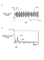
- the tap interval distribution skewness 5027 (characteristic amount related to the variation in tapping time interval) (see FIG. 5) is the tap interval frequency distribution 9100 (histogram) of the total measurement time as shown in FIG. It is skewness.
- the skewness is a statistical index representing the asymmetry of the distribution, and can be obtained, for example, by dividing the average of the third power of the deviation (difference from the average value) by the third power of the standard deviation. .
- the frequency distribution of tap intervals for healthy individuals is considered to be close to a normal distribution, whereas in diseases such as dementia, long tap intervals may occasionally be mixed. Therefore, it is considered that the frequency distribution has a shape in which the skirt on the positive direction side (the right side of the horizontal axis in FIG. 9A) extends.
- the tap interval distribution skewness 5027 can represent this property. That is, it is considered that the skewness is close to “0” in the case of the frequency distribution of healthy persons, and is relatively large in the case of the frequency distribution of dementia patients.
- the kurtosis 5028 near the maximum point is a value obtained by averaging the kurtosis of the maximum point of the distance waveform over the entire measurement time.
- the kurtosis is a statistical index representing the degree of sharpness of the distribution, and can be obtained, for example, by dividing the average of the fourth power of the deviation (difference from the average value) by the fourth power of the standard deviation.
- a distance waveform of a certain value for example, 55 mm
- kurtosis is calculated for the distance waveform.
- the kurtosis 5028 near the maximum point can represent muscle stiffness (muscular rigidity). This is because if the muscles are stiff, the switching between the opening operation and the closing operation cannot be performed smoothly, and the distance waveform in the vicinity of the maximum point is thought to be sharp because it switches abruptly.
- the time delay locus stability 5029 plots the finger tapping motion with the motion waveform X (t) at time t and the motion waveform X (t + k) at time t + k as two axes. It is a value (feature value) representing the stability of the trajectory 10100 of X (t) and X (t + k) (the time delay k is an arbitrary constant value, for example, about 20 milliseconds).
- This trajectory plotting method is used in the field of chaotic time series analysis for evaluating the periodicity and stability of time series data.
- the stability of the finger tapping motion can be evaluated by the shape of the trajectory.
- the trajectory 10100 of X (t) and X (t + k) is an elliptical shape that rises to the right for both the dominant and non-dominant hands in an elderly healthy person and is stable in each cycle (see FIG. 10A).
- the dominant hand is elliptical and stable, but the non-dominant hand shows that the trajectory is unstable (see FIG. 10B).
- the attractor is drawn with two axes of X (t) and X (t + k). However, the attractor may be drawn with three or more axes such as X (t), X (t + k), and X (t + 2k).
- the data may be normalized by the distance value when the two fingers are opened to the maximum.
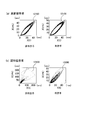
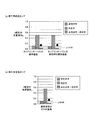
- FIG. 11 shows the significance probability indicating the presence / absence of a significant difference in both-hands difference feature amount between an elderly healthy person and a dementia patient.
- the standard deviation of the tap interval feature amount 5022
- Feature and local standard deviation of the tap interval
- the difference between the features of the two-handed hand is smaller than the features of the non-dominant hand and the feature of the dominant hand.
- ignificance probability p ⁇ 0.05 the difference between the features of the two-handed hand is smaller than the features of the non-dominant hand and the feature of the dominant hand.
- the number of velocity waveform zero crossings is a non-dominant hand. It can be seen that the two-hand difference feature amount has a lower significance probability and a significant difference is recognized (significance probability p ⁇ 0.05) than the feature amount and the dominant hand feature amount.
- the feature amount of the dominant hand may be subtracted from the feature amount of the dominant hand, or the feature amount of the non-dominant hand may be subtracted from the feature amount of the dominant hand, Alternatively, the feature amount of the non-dominant hand may be divided by the feature amount of the dominant hand, or the feature amount of the dominant hand may be divided by the feature amount of the non-dominant hand. That is, using the feature amounts of both hands, a difference (a subtraction value obtained by subtracting one from the other) or a division value obtained by dividing one by the other is calculated as a both-hand difference feature amount.
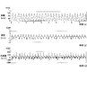
- Non-dominant hand / handedness fluctuation cycle In the task of tapping movement of both hands at the same time (two-hand simultaneous finger tapping), it is ideal that there is no waveform shift between both hands. In a healthy person, it is easy to move both hands at the same time without deviation, and even if a deviation occurs, it can be corrected to immediately eliminate the deviation. However, as the cognitive function declines, it is difficult to move both hands at the same time, and when a shift occurs, it becomes difficult to recognize and eliminate the shift.
- the difference between the motion waveforms (time-series data) of both hands is calculated to obtain a two-hand difference waveform 12100.
- the two-hand difference waveform 12100 is always 0 if there is no deviation between the waveforms of both hands, and takes a large value if the deviation is large.
- the two-hand differential waveform 12100 includes two types of frequencies: the same first frequency as the finger tapping movement (about 2 to 5 Hz for a healthy person) and the second frequency of the fluctuation cycle 12200 for eliminating the deviation of both hands. Yes.
- a frequency spectrum 12300 (frequency component) is obtained by applying Fourier transform to the two-handed differential waveform, and each frequency corresponding to two peak values of the intensity of the frequency spectrum 12300 is obtained.
- the larger one is the first frequency 12400 and the smaller one is the second frequency 12500 (two-hand difference feature value).
- the signal control unit 1230 (see FIG. 1) transmits a signal for starting measurement to the motor function measuring device 1100 in response to the operation signal sent from the operation input unit 1300.
- the motor function measuring apparatus 1100 is in a standby state when no measurement is performed, and enters a state where measurement is possible by a signal from the signal control means 1230.
- the subject information processing means 1240 manages such information using a subject DB (Data Base) that records information such as subject information and analysis results in the storage unit 1260.
- a subject DB Data Base
- the subject information processing means 1240 includes 1) registration, correction, deletion and search, sorting of subject information, 2) association of subject information with measurement data, 3) registration and correction of measurement data analysis results, Deletion (addition, correction, and deletion of items), 4)
- the subject information registered in the subject DB includes subject ID (Identifier), name, date of birth, age, height, weight, disease name, comments about the subject, and the like.
- subject ID Identity
- the information management by the subject information processing means 1240 can be easily realized by a conventionally known program and data configuration.
- the output processing unit 1250 displays information such as subject information and analysis results registered in the subject DB on the display unit 1400 in a display format that is easy to visually understand using a graph or table format as appropriate. It is what is displayed. Note that the output processing unit 1250 does not need to display all the analysis results described above at the same time, and can be configured to display items appropriately selected by the operator via the operation input unit 1300.
- the control unit 1270 includes a CPU (Central Processing Unit), a ROM (Read Only Memory), a RAM (Random Access Memory), and the like.
- Each means in the data processing unit 1220, the signal control unit 1230, the subject information processing unit 1240, and the output processing unit 1250 load the program or data stored in the storage unit 1260 into the control unit 1270 and execute arithmetic processing. Is realized.
- the operation input unit 1300 (see FIG. 1) is used by an operator of the cerebral dysfunction evaluation system 1000 to input subject information, and can be realized by a keyboard, a mouse, or the like. Further, when inputting subject information, an input screen may be displayed on the display as a user interface for assisting input by the operator.
- the display unit 1400 (see FIG. 1) outputs subject information and exercise information processed by the data processing unit 1220.
- an LCD Liquid Crystal Display
- a CRT Cathode Ray Tube
- printer etc.
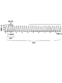
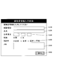
- the subject information input screen includes a subject ID input field 13100, a name input field 13200, a birth date input field 13300, a dominant hand input field 13400, and a memo input field 13500.
- the measurer inputs each piece of information in these input fields and clicks the save button 13600 with the mouse
- the entered subject information is saved in the storage unit 1260 by the subject information processing means 1240.
- the dominant hand information is used in the calculation of the two-hand difference feature quantity generation unit 1222.
- the measurement is started when the measurer (doctor or the like) presses the measurement execution button 14100, and the motion waveform 14300 being measured is drawn.
- the measurer doctor or the like
- the motion waveform is saved and the analysis result obtained by each means of the data processing unit 1220 is saved.
- the severity of dementia can be evaluated based on the two-hand difference feature amount calculated by the two-hand difference feature amount generation unit 1222.
- the computer can realize each function based on the program. .
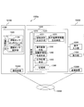
- FIG. 15 is a diagram illustrating an example of the overall configuration of a brain dysfunction evaluation system 1000a according to a modification.
- a brain dysfunction evaluation system 1000a shown in FIG. 15 separates functions substantially equivalent to the cerebral dysfunction evaluation system 1000 shown in FIG. 1 into a terminal device 15100 and a server device 15200 connected to each other by a communication network 15300. It was realized.
- the terminal device 15100 plays a role of presenting physical movement to the subject and acquiring physical movement data of the subject.
- the server device 15200 receives the data of the physical movement of the subject acquired by the terminal device 15100 via the communication network 15300, and determines the severity of the cognitive function decline of the subject based on the data of the physical movement of the subject. Play a role to evaluate.
- the configuration and function of the cerebral dysfunction evaluation system 1000a are the same as the configuration and function of the cerebral dysfunction evaluation system 1000 shown in FIG. 1, and therefore only the differences will be described below. To do.
- a communication device 15400 (first communication device) that is connected to the communication network 15300 is newly provided.
- the server device 15200 includes a communication device 15500 (second communication device) connected to the communication network 15300 in addition to the brain function failure evaluation device 1200, the operation input unit 1300, and the display unit 1400 of the brain function disorder evaluation system 1000 of FIG. Newly provided.
- Information transmitted from the communication device 1540 to the communication device 15500 via the communication network 15300 is time-series data of motion waveforms.
- the terminal device 15100 having the above-described configuration can be realized by a personal computer, a tablet terminal, a smartphone, or the like included in a doctor, a subject, or an assistant thereof.
- the server device 15200 can be realized by a high-performance personal computer, workstation, general-purpose computer, or the like.
- a plurality of terminal devices 15100 may be connected to one server device 15200 via the communication network 15300.
- the terminal device 15100 simply acquires data on the physical movement of the subject. Therefore, for example, even if the terminal device 15100 is lost, data on the degree of cognitive impairment of the subject does not flow out. Moreover, evaluation results such as the degree of cognitive dysfunction of the subject are stored in the storage unit 1260 of the server device 15200, which makes it easier for related doctors, nurses, caregivers, and the like to access. Further, by providing the server device 15200, the server device 15200 of the cerebral dysfunction evaluation system 1000a is connected to a system that manages other medical information / health information such as an electronic medical record system, a medication recording system, and a health management system. It becomes easy.
- the present invention is not limited to the above-described embodiment, and includes various modifications.
- the above embodiment has been described in detail for easy understanding of the present invention, and is not necessarily limited to the one having all the configurations described.
- a part of the configuration of an embodiment can be replaced with a part of the configuration of another embodiment, and further, a part or all of the configuration of the other embodiment is added to the configuration of the certain embodiment. Is also possible.
- specific configurations and processes can be appropriately changed without departing from the gist of the present invention.
Landscapes
- Health & Medical Sciences (AREA)
- Life Sciences & Earth Sciences (AREA)
- Engineering & Computer Science (AREA)
- Physics & Mathematics (AREA)
- Public Health (AREA)
- Veterinary Medicine (AREA)
- Biophysics (AREA)
- Pathology (AREA)
- General Health & Medical Sciences (AREA)
- Biomedical Technology (AREA)
- Heart & Thoracic Surgery (AREA)
- Medical Informatics (AREA)
- Molecular Biology (AREA)
- Surgery (AREA)
- Animal Behavior & Ethology (AREA)
- Physiology (AREA)
- Neurology (AREA)
- Psychiatry (AREA)
- Oral & Maxillofacial Surgery (AREA)
- Dentistry (AREA)
- Child & Adolescent Psychology (AREA)
- Computer Vision & Pattern Recognition (AREA)
- Signal Processing (AREA)
- Artificial Intelligence (AREA)
- Developmental Disabilities (AREA)
- Hospice & Palliative Care (AREA)
- Mathematical Physics (AREA)
- Psychology (AREA)
- Neurosurgery (AREA)
- Computer Networks & Wireless Communication (AREA)
- Measurement Of The Respiration, Hearing Ability, Form, And Blood Characteristics Of Living Organisms (AREA)
- Measurement And Recording Of Electrical Phenomena And Electrical Characteristics Of The Living Body (AREA)
Abstract
両手協調運動における両手の運動機能の差異を算出することで、認知機能低下をはじめとする脳機能障害の程度を容易に評価することを課題とする。本発明は、運動センサから取得した被験者の両手それぞれの手指運動に関する時系列データを記憶する記憶部(1260)と、記憶部(1260)に記憶された時系列データを解析するデータ処理部(1220)と、データ処理部(1220)により解析された解析結果を表示する表示部(1400)と、を備える脳機能障害評価システム(1000)である。データ処理部(1220)は、記憶部(1260)に記憶された時系列データに基づいて、時系列データに対応する運動波形を生成する運動波形生成手段(1221)と、被験者の両手それぞれの前記運動波形に基づいて、両手それぞれの手指運動の差異を表す両手差異特徴量を生成する両手差異特徴量生成手段(1222)とを含む。
Description
本発明は、認知機能低下をはじめとする脳機能障害の程度を評価する技術に関する。
近年、高齢化社会の進行に伴い、認知症の患者数が増大し、現在、日本国内には200万人もの認知症患者がいると言われている。認知症では、記憶障害、見当識障害、学習障害などが生じ、日常生活に大きな支障を来たす。また、暴言、暴力、徘徊、不潔行為などの問題行動が見られる場合もある。さらに、認知症の末期には、小刻み歩行や前傾姿勢などの運動障害が表れ、最終的には寝たきり状態に陥る。
認知症としては、アルツハイマー型認知症、脳血管性認知症、レビー小体型認知症の三大認知症がある。また、認知症では、その他に、パーキンソン病などの運動障害や、うつ病や統合失調症などの精神疾患に併発して認知機能が低下する場合がある。診断により認知症の種類を特定できると、それに合わせた薬物療法等の適切な治療が可能となる。いずれの種類の認知症も、早期に発見し、適切な薬を投与することで、軽度の状態で進行を抑制できる。これらのことから、認知症になる可能性の高い健常高齢者を対象に、認知症を早期に発見するためのスクリーニング検査が必要である。
認知症の診断は、長谷川式スケールやMMSE(Mini Mental State Examination)などのように、記憶、判断などの認知機能を調べる検査が主流である。しかしながら、これらの診断方法は、医師が対面で数分~数10分かけて行うもので、時間的制約などの観点から、多数の被験者を対象にしたスクリーニング検査に適しているとは言えない。
また、CT(Computed Tomography)、MRI(Magnetic Resonance Imaging)を用いて脳の萎縮の有無を調べる方法や、SPECT(Single Photon Emission Computed Tomography)、PET(Positron Emission Tomography)を用いて認知症の原因物質であるアミロイドベータの蓄積状況を調べる方法などの脳画像計測による診断も行われている。しかしながら、これらの脳画像計測は、検査費が高額で、検査時間も長くかかるため、多数の被験者を対象にしたスクリーニング検査に適しているとは言えない。
上記の認知機能検査や脳画像計測に対して、手指の運動を計測することで認知機能低下を検出可能であることが指摘されている。一般に、認知機能に障害を受けると、四肢の協調動作や、外部刺激に追従した身体運動が困難になると考えられている。そして、このような身体運動の機能低下は、とくに巧緻性の高い運動を行う手指で早期に観察されやすい。そのため、手指の運動を電子機器で計測すれば、その結果に基づき認知症を早期に発見できる可能性がある。
従来の発明として、例えば、特許文献1、特許文献2、特許文献3、非特許文献1などには、ボタン押し装置・タブレットコンピュータ・磁気センサなど、手指の運動を簡易に計測できる装置を用いることにより、医師に頼らず、被験者の認知機能を簡易的に評価する評価システムの例が開示されている。また、特許文献4では、両手の指タッピング運動(2指(親指と人差し指など)の繰り返す開閉運動)における位相差を評価することで、認知機能低下を表す方法が提案されている。
Robbins T. W. et al.、 "Cambridge Neuropsychological Test Automated Battery (CANTAB): a factor analytic study of a large sample of normal elderly volunteers"、Dementiaand Geriatric Cognitive Disorders、 Switzerland、 1994、 Vol.5、 No.5、 pp.266-281
認知機能の低下が進むと両手の運動機能の差異が大きくなると言われているため、両手の運動機能の差異を算出する方法が有効である。その観点では、特許文献1、特許文献2、特許文献3、非特許文献1の技術では、片手の手指運動を計測しているため、両手の運動機能の差異を評価することはできない。また、特許文献4では、両手の指タッピング運動における位相差を評価する方法が提案されているが、両手の運動機能の差異を明示的に算出していないため、上記目的には合致しない。
そこで、本発明は、両手協調運動における両手の運動機能の差異を算出することで、認知機能低下をはじめとする脳機能障害の程度を容易に評価することを課題とする。
前記課題を解決するために、本発明は、運動センサから取得した被験者の両手それぞれの運動に関する時系列データを記憶する記憶手段と、前記記憶手段に記憶された前記時系列データを解析する解析手段と、前記解析手段により解析された解析結果を表示する表示手段と、を備える脳機能障害評価システムであって、前記解析手段は、前記記憶手段に記憶された前記時系列データに基づいて、前記時系列データに対応する運動波形を生成する運動波形生成手段と、前記被験者の両手それぞれの前記運動波形に基づいて、両手それぞれの運動の差異を表す両手差異特徴量を生成する両手差異特徴量生成手段と、を含むことを特徴とする脳機能障害評価システムである。
その他の手段については後記する。
その他の手段については後記する。
本発明によれば、両手協調運動における両手の運動機能の差異を算出することで、認知機能低下をはじめとする脳機能障害の程度を容易に評価することができる。
以下、本発明を実施するための形態(以下「実施形態」という。)について、図面を参照して詳細に説明する。
なお、以下に説明する本実施形態では、脳機能障害とは、いわゆる認知機能低下を発症するもの全般(アルツハイマー型認知症、脳血管性認知症、レビー小体型認知症、パーキンソン病、水頭症、うつ病、統合失調症など)を総称するものするが、脳卒中などによる運動障害などを含む。また、本実施形態の説明では、脳機能障害を単に認知症という場合もある。
なお、以下に説明する本実施形態では、脳機能障害とは、いわゆる認知機能低下を発症するもの全般(アルツハイマー型認知症、脳血管性認知症、レビー小体型認知症、パーキンソン病、水頭症、うつ病、統合失調症など)を総称するものするが、脳卒中などによる運動障害などを含む。また、本実施形態の説明では、脳機能障害を単に認知症という場合もある。
[全体構成]
図1に示すように、本実施形態に係る脳機能障害評価システム1000は、被験者の手指運動を測定する運動機能測定装置1100と、運動機能測定装置1100によって測定されたデータの記録及び解析を行う脳機能障害評価装置1200と、被験者の情報等を入力する操作入力部1300と、測定結果や解析結果を出力し前記出力されたデータを表示する表示部1400(表示手段)と、を含んで構成される。
図1に示すように、本実施形態に係る脳機能障害評価システム1000は、被験者の手指運動を測定する運動機能測定装置1100と、運動機能測定装置1100によって測定されたデータの記録及び解析を行う脳機能障害評価装置1200と、被験者の情報等を入力する操作入力部1300と、測定結果や解析結果を出力し前記出力されたデータを表示する表示部1400(表示手段)と、を含んで構成される。
ここで、被験者とは、運動機能測定装置1100による測定対象であり、本実施形態においては、認知症の有無または重症度の検査を希望する人である。
また、運動機能測定装置1100は、被験者に手指運動を行わせた際の指の動作を測定するものである。ここで、手指運動とは、磁気センサによって計測された指タッピング運動(手の親指と人差し指を可能な限り速く、かつ可能な限り大きく繰り返し開閉させる運動)や、タッチパネルセンサ(画面接触型センサ)を有するタブレット端末などの画面上をタッチしたりスライドしたりする運動を含む。以下、手指運動とは、指タッピング運動とする。
また、運動機能測定装置1100は、被験者に手指運動を行わせた際の指の動作を測定するものである。ここで、手指運動とは、磁気センサによって計測された指タッピング運動(手の親指と人差し指を可能な限り速く、かつ可能な限り大きく繰り返し開閉させる運動)や、タッチパネルセンサ(画面接触型センサ)を有するタブレット端末などの画面上をタッチしたりスライドしたりする運動を含む。以下、手指運動とは、指タッピング運動とする。
[運動機能測定装置]
運動機能測定装置1100は、被験者の手指運動の情報(以下、単に「運動情報」ともいう。)を時系列に検出するものであって、少なくとも、距離、速度、加速度、躍度(加速度を時間微分したもの)のいずれか1つに関する被験者の運動情報を、時系列データ(波形データ)として取得するものである。
運動機能測定装置1100は、被験者の手指運動の情報(以下、単に「運動情報」ともいう。)を時系列に検出するものであって、少なくとも、距離、速度、加速度、躍度(加速度を時間微分したもの)のいずれか1つに関する被験者の運動情報を、時系列データ(波形データ)として取得するものである。
運動機能測定装置1100は、運動センサ1110と、運動センサインタフェース1120と、運動センサ制御部1130とを備えて構成される。
運動センサインタフェース1120と、運動センサ制御部1130は、1つの筐体である収容部1500に収容されている。なお、1つの筐体に入れなくてもよい。
運動センサインタフェース1120と、運動センサ制御部1130は、1つの筐体である収容部1500に収容されている。なお、1つの筐体に入れなくてもよい。
≪運動センサ≫
図2に示すように、運動センサ1110は、磁場を発信する発信コイル2100と、この磁場を受信(検出)する受信コイル2200によって構成される。
発信コイル2100は親指の爪部に、受信コイル2200は人差し指の爪部に、例えば両面テープ等によって、それぞれ装着される。なお、取り付ける指を逆にして、発信コイル2100を人差し指の爪部に、受信コイル2200を親指の爪部に装着してもよい。
図2に示すように、運動センサ1110は、磁場を発信する発信コイル2100と、この磁場を受信(検出)する受信コイル2200によって構成される。
発信コイル2100は親指の爪部に、受信コイル2200は人差し指の爪部に、例えば両面テープ等によって、それぞれ装着される。なお、取り付ける指を逆にして、発信コイル2100を人差し指の爪部に、受信コイル2200を親指の爪部に装着してもよい。
また、発信コイル2100と受信コイル2200の被装着部位は、親指と人差し指の爪部として説明しているが、これに限定されるものではなく、例えば、爪部以外の指部分であってもよい。
また、親指と人差し指に限定されることなく、例えば、親指と小指等の別の組み合わせの指に装着してもよい。さらに、被装着部位は被験者の爪部又は指に限定されることなく、例えば、指に近接する手のひら等の周辺部位も含まれる。従って、発信コイル2100と受信コイル2200の被装着部位は、手指運動を検出できるのであれば、被験者の爪部、指、及び指の周辺部位のいずれでもよい。
また、親指と人差し指に限定されることなく、例えば、親指と小指等の別の組み合わせの指に装着してもよい。さらに、被装着部位は被験者の爪部又は指に限定されることなく、例えば、指に近接する手のひら等の周辺部位も含まれる。従って、発信コイル2100と受信コイル2200の被装着部位は、手指運動を検出できるのであれば、被験者の爪部、指、及び指の周辺部位のいずれでもよい。
≪運動センサインタフェース≫
運動センサインタフェース1120(図1参照)は、アナログ/デジタル変換回路を含み、運動センサ1110によって検出されたアナログ信号の波形データを、所定のサンプリング周波数でデジタル信号の波形データに変換し、前記変換されたデジタル信号が運動センサ制御部1130(図1参照)に導入される。
運動センサインタフェース1120(図1参照)は、アナログ/デジタル変換回路を含み、運動センサ1110によって検出されたアナログ信号の波形データを、所定のサンプリング周波数でデジタル信号の波形データに変換し、前記変換されたデジタル信号が運動センサ制御部1130(図1参照)に導入される。
≪運動センサ制御部≫
図3は、運動センサ制御部1130の構成等を示したブロック図である(運動センサインタフェース1120の図示は省略している)。ここで、運動センサ制御部1130が波形データを取得する手順について説明する。
図3は、運動センサ制御部1130の構成等を示したブロック図である(運動センサインタフェース1120の図示は省略している)。ここで、運動センサ制御部1130が波形データを取得する手順について説明する。
図3において、交流発生回路3100によって特定の周波数(例えば、20kHz等)を持つ交流電圧が作成される。交流発生回路3100によって作成された特定の周波数を持つ交流電圧は、電流発生用アンプ回路3200によって特定の周波数を持つ交流電流に変換され、その変換された交流電流が発信コイル2100に流れる。発信コイル2100を流れる交流電流によって発生した磁場は、受信コイル2200に誘導起電力を発生させる。
誘導起電力によって受信コイル2200に発生した交流電流(交流発生回路3100によって作成された特定の周波数を持つ交流電圧と同じ周波数を有している。)は、プリアンプ回路3300によって増幅され、増幅後の信号は検波回路3400に入力される。検波回路3400では、交流発生回路3100によって作成された特定の周波数又は2倍周波数によって、前記した増幅後の信号の検波を行う。つまり、高周波が含まれる波形から、手指同士の距離の変化に伴う電圧の変動分を取り出す。そのため、交流発生回路3100の出力を、位相調整回路3600によって位相を調整した後、参照信号3700として検波回路3400の参照信号入力端子に導入する。
検波回路3400の出力信号は、高周波成分を除去するためのLPF(Low-Pass Filter)回路3500を通過した後、所望の電圧を得るためにアンプ回路3800によって増幅されて脳機能障害評価装置1200に導入される。アンプ回路3800の出力信号3900は、親指と人差し指にそれぞれ装着された発信コイル2100と受信コイル2200との相対距離Dに対応する電圧値を表す(相対距離と電圧値の変換式については後記)。
以上、運動センサ1110として磁気センサを用いた場合について説明したが、その代わりに、加速度センサやストレインゲージ、高速度カメラ等を用いてもよい。また、タブレット端末やスマートフォンなどの画面上で、1本以上の指をタッチまたはスライドさせることで手指運動を計測してもよい。
[脳機能障害評価装置]
脳機能障害評価装置1200(図1参照)は、運動機能測定装置1100によって測定されたデータの記録や解析を行うものである。ここで、脳機能障害評価装置1200は、運動センサ制御部1130からの出力信号(時系列データ)を入力するデータ入力部1210と、前記入力した出力信号を解析するデータ処理部1220(解析手段)と、運動機能測定装置1100へ測定の開始のための信号を送信する信号制御手段1230と、被験者情報処理手段1240と、データ処理部1220の解析結果を表示部1400に出力できる形式に処理する出力処理手段1250と、データ処理部1220と被験者情報処理手段1240の処理するデータを保存する記憶部1260(記憶手段)と、データの受け渡しや演算処理などの制御を行う制御部1270と、を含んで構成される。
脳機能障害評価装置1200(図1参照)は、運動機能測定装置1100によって測定されたデータの記録や解析を行うものである。ここで、脳機能障害評価装置1200は、運動センサ制御部1130からの出力信号(時系列データ)を入力するデータ入力部1210と、前記入力した出力信号を解析するデータ処理部1220(解析手段)と、運動機能測定装置1100へ測定の開始のための信号を送信する信号制御手段1230と、被験者情報処理手段1240と、データ処理部1220の解析結果を表示部1400に出力できる形式に処理する出力処理手段1250と、データ処理部1220と被験者情報処理手段1240の処理するデータを保存する記憶部1260(記憶手段)と、データの受け渡しや演算処理などの制御を行う制御部1270と、を含んで構成される。
≪データ処理部≫
データ処理部1220(図1参照)は、データ入力部1210から送給され制御部1270を通して得られた出力信号に基づいて、被験者の指タッピング運動の運動波形を算出(生成)し、認知症の重症度を表す客観的な指標を算出する。各情報は適宜、記憶部1260に格納される。
ここで、データ処理部1220は、運動波形生成手段1221と、両手差異特徴量生成手段1222とを含んで構成される。
データ処理部1220(図1参照)は、データ入力部1210から送給され制御部1270を通して得られた出力信号に基づいて、被験者の指タッピング運動の運動波形を算出(生成)し、認知症の重症度を表す客観的な指標を算出する。各情報は適宜、記憶部1260に格納される。
ここで、データ処理部1220は、運動波形生成手段1221と、両手差異特徴量生成手段1222とを含んで構成される。
<運動波形生成手段>
運動波形生成手段1221(図1参照)は、運動機能測定装置1100から送給された電圧出力の時系列データ(波形データ)を、対応する運動波形に変換し、変換された運動波形を時間微分又は時間積分することによって、距離波形と、速度波形と、加速度波形とを補完的に生成するものである(詳細は後記)。
運動波形生成手段1221(図1参照)は、運動機能測定装置1100から送給された電圧出力の時系列データ(波形データ)を、対応する運動波形に変換し、変換された運動波形を時間微分又は時間積分することによって、距離波形と、速度波形と、加速度波形とを補完的に生成するものである(詳細は後記)。
ここで、電圧出力(電圧値)を運動波形(相対距離波形など)に変換するための変換式は、例えば、長さの異なる複数のブロック(例えば長さが20、30、60mmのブロック)を一体化したキャリブレーションブロックを用いて、その複数の長さ(20、30、60mm)それぞれの部分を二指で持った際に得られる電圧値と距離値のデータセットから、そのデータセットとの誤差を最小にする近似曲線として求められる。
図4は、前記波形データを変換式によって変換して得られた距離波形4100と、距離波形4100を時間微分することで得られた速度波形4200と、速度波形4200を時間微分することで得られた加速度波形4300を示す図である。なお、「運動波形」とは、特に限定しない限り、距離波形、速度波形、加速度波形及び躍度波形のうち、少なくとも1つを含む。また、運動機能測定装置1100として、ストレインゲージや加速度計等を適用した場合であっても、少なくとも1つの運動波形が測定されれば、微積分演算することによって補完的に他の運動波形(距離、速度、加速度、躍度)を求めることができる。
<両手差異特徴量生成手段>
両手差異特徴量生成手段1222(図1参照)は、運動波形生成手段1221から得られた運動波形から、両手それぞれの手指運動の差異を表す両手差異特徴量を生成する。本実施形態において、両手差異特徴量の算出には、二通りの方法がある。一つ目は、右手・左手の運動波形から個別に特徴量を算出した後、2つの特徴量の差分を算出する方法(第1の両手差異特徴量算出方法)である。二つ目の方法は、右手と左手の運動波形の差分となる時系列データを算出した後、その差分波形について特徴量を算出する方法(第2の両手差異特徴量算出方法)である。以下、これらの二通りの方法について説明する。
両手差異特徴量生成手段1222(図1参照)は、運動波形生成手段1221から得られた運動波形から、両手それぞれの手指運動の差異を表す両手差異特徴量を生成する。本実施形態において、両手差異特徴量の算出には、二通りの方法がある。一つ目は、右手・左手の運動波形から個別に特徴量を算出した後、2つの特徴量の差分を算出する方法(第1の両手差異特徴量算出方法)である。二つ目の方法は、右手と左手の運動波形の差分となる時系列データを算出した後、その差分波形について特徴量を算出する方法(第2の両手差異特徴量算出方法)である。以下、これらの二通りの方法について説明する。
(第1の両手差異特徴量算出方法)
[片手の運動波形から算出される特徴量]
図5は、特徴量の名称と定義を示す図である。以下では、必要な用語を説明した後、特徴量番号5023~5029の特徴量を詳細に説明する。なお、特徴量番号5001~5022の特徴量については、図5に示した定義の通りであるので、詳細な説明を省略する。また、以下において、「特徴量番号50※※の特徴量」を「特徴量50※※」とも表記する。
[片手の運動波形から算出される特徴量]
図5は、特徴量の名称と定義を示す図である。以下では、必要な用語を説明した後、特徴量番号5023~5029の特徴量を詳細に説明する。なお、特徴量番号5001~5022の特徴量については、図5に示した定義の通りであるので、詳細な説明を省略する。また、以下において、「特徴量番号50※※の特徴量」を「特徴量50※※」とも表記する。
図6に示すように、指タッピング運動の周期6100とは、距離値が距離波形の計測時間中の平均値6200と交差し、かつ速度が0より小さくなった時点から、次に同じ条件になる時点までと定義する。タップインターバルとは、その1周期の長さとする。そして、1周期内で距離値が最小となる点を距離波形の極小点6300とし、そのときの距離値を極小値とする。同様に、1周期内で距離値が最大となる点を距離波形の極大点6400とし、そのときの距離値を極大値とする。さらに、距離波形の極小点から次の極大点までをオープニング動作6500、距離波形の極大点から次の極小点までをクロージング動作6600と定義する。
速度波形のゼロ交差回数5023(特徴量5023。以下、他についても同様に表記する場合がある。)(図5参照)とは、計測時間中に速度が正値から負値になった回数から、タッピング回数5019を引いた値である。なお、速度が正値から負値になった回数は、速度が負値から正値になった回数としてもよい。
速度波形のゼロ交差回数5023は、図7(a)で示したような、距離波形に表れた指タッピング運動の大きな運動以外の細かい上下運動7100の個数を数えるための特徴量である。速度波形がゼロを交差する回数が、距離波形の細かい上下運動の回数に対応している。このような距離波形の細かい上下運動の回数は、一般に、健常者よりも認知症患者のほうが多い。
同様に、加速度波形のゼロ交差回数5024(図5参照)とは、計測時間中に加速度が正値から負値になった回数から、タッピング回数5019を引いた値である。なお、加速度が正値から負値になった回数は、加速度が負値から正値になった回数としてもよい。
加速度波形のゼロ交差回数5024は、図7(b)に示すように、細かい上下運動に限らず、指タッピング運動の途中で不自然に勢いの強弱が変化した回数部分7200を数えるための特徴量である。加速度波形がゼロを交差する回数が、距離波形で不自然に勢いの強弱が変化した回数に対応している。このような距離波形で不自然に勢いの強弱が変化した回数は、一般に、健常者よりも認知症患者のほうが多い。
距離波形の極大値の局所的な標準偏差5025(図5参照)とは、図8で示したように、距離波形の近傍n個の距離の極大値の標準偏差(連続するn周期分の距離波形に関するそれぞれの距離の極大値の標準偏差)を全計測時間にわたって平均した値である。nは、2以上で、かつタッピング回数よりも小さい整数であれば、いくつでもよい。
タップインターバルの局所的な標準偏差5026(タッピングの時間間隔のばらつきに関する特徴量)(図5参照)とは、近傍n個のタップインターバルの標準偏差を、全計測時間にわたって平均した値である。nは、2以上で、かつタッピング回数よりも小さい整数であれば、いくつでもよい。
認知症などの疾患では、全計測時間にわたって局所的な振幅の変動が大きいと考えられる。一方で、健常者では局所的な振幅の変動はあまりないが、疲労のために全計測時間にわたって徐々に振幅が小さくなると考えられる。距離波形の極大値の標準偏差5005は全計測時間にわたって標準偏差を計算するため両者(認知症患者と健常者)の違いを表すことが困難である。一方、距離波形の極大値の局所的な標準偏差5025は、局所的な振幅の変動を表すため、全計測時間にわたって継続的に局所的な標準偏差を算出することで、両者の違いを表すことができると考えられる。同様に、タップインターバルの局所的な標準偏差5026も、両者の違いを表すことができると考えられる。
タップインターバルの分布の歪度5027(タッピングの時間間隔のばらつきに関する特徴量)(図5参照)とは、図9(a)で示すような全計測時間のタップインターバルの頻度分布9100(ヒストグラム)の歪度である。ここで、歪度とは、分布の非対称性を表す統計的指標であり、例えば、偏差(平均値との差)の3乗の平均を標準偏差の3乗で除算することで求めることができる。
健常者のタップインターバルの頻度分布は正規分布に近い形になると考えられるのに対して、認知症などの疾患では、時折長いタップインターバルが混入する場合がある。そのため、正方向側(図9(a)の横軸の右側)の裾が延びた形状の頻度分布になると考えられる。タップインターバルの分布の歪度5027は、この性質を表すことができる。つまり、当該歪度が、健常者の頻度分布の場合は「0」に近く、認知症患者の頻度分布の場合は比較的大きな値になると考えられる。
極大点付近の尖度5028(図5参照)とは、距離波形の極大点の尖度を、全計測時間にわたって平均した値である。ここで、尖度とは、分布の尖り具合を表す統計的指標であり、例えば、偏差(平均値との差)の4乗の平均を標準偏差の4乗で除算することで求めることができる。図9(b)に示したように、一定値(例えば55mm)以上の距離波形を極大点付近の距離波形9200として、それに対して尖度を計算する。
極大点付近の尖度5028は、筋肉のこわばり(筋固縮)を表すことができると考えられる。筋肉がこわばると、オープニング動作とクロージング動作の切り替えを滑らかに行えず急激に切り替えるために、極大点付近の距離波形が尖ると考えられるからである。
[カオス時系列の軌跡]
時間遅れ軌跡の安定性5029(図5参照)とは、図10のように、時刻tの運動波形X(t)と時刻t+kの運動波形X(t+k)を2軸にとって指タッピング運動をプロットしたX(t)とX(t+k)の軌跡10100の安定性を表す値(特徴量)である(時間遅れkは任意の一定値で例えば20ミリ秒程度)。この軌跡のプロット法は、時系列データの周期性や安定性を評価するためのカオス時系列解析という分野で用いられている。上記軌跡の形状により、指タッピング運動の安定性を評価することができる。X(t)とX(t+k)の軌跡10100は、高齢健常者では、利き手・非利き手ともに、右上がりの楕円形となり、各周期で安定している(図10(a)参照)。一方で、認知症患者では、利き手では、楕円形となり安定しているものの、非利き手では、軌跡が不安定であることが分かる(図10(b)参照)。
時間遅れ軌跡の安定性5029(図5参照)とは、図10のように、時刻tの運動波形X(t)と時刻t+kの運動波形X(t+k)を2軸にとって指タッピング運動をプロットしたX(t)とX(t+k)の軌跡10100の安定性を表す値(特徴量)である(時間遅れkは任意の一定値で例えば20ミリ秒程度)。この軌跡のプロット法は、時系列データの周期性や安定性を評価するためのカオス時系列解析という分野で用いられている。上記軌跡の形状により、指タッピング運動の安定性を評価することができる。X(t)とX(t+k)の軌跡10100は、高齢健常者では、利き手・非利き手ともに、右上がりの楕円形となり、各周期で安定している(図10(a)参照)。一方で、認知症患者では、利き手では、楕円形となり安定しているものの、非利き手では、軌跡が不安定であることが分かる(図10(b)参照)。
安定性を評価するために、各周期の軌跡と最も内側の軌跡との差分の面積を算出し、その平均値を算出し、時間遅れ軌跡の安定性5029(特徴量)とする。時間遅れ軌跡の安定性5029が大きいほど、計測時間中の指タッピング運動の周期が安定していないこととなる。なお、上記では、X(t)とX(t+k)の2軸でアトラクタを描画したが、X(t)とX(t+k)とX(t+2k)など3軸以上で描画してもよい。
図5に示した特徴量番号5001~5029の特徴量においては、標準偏差の代わりに、分散などデータのばらつきを表す別の統計的指標を用いてもよい。また、手の大きさが異なる人のデータも同等に扱うために、2指を最大に開いたときの距離値で規格化してもよい。
[両手差異特徴量]
利き手と非利き手それぞれの指タッピング運動について、特徴量5001~5029を算出し、非利き手の特徴量から利き手の特徴量を減算した特徴量を、両手差異特徴量とする。認知機能低下が進むと、利き手と非利き手の運動機能の差が大きくなるといわれている。一方で、利き手と非利き手には、被験者固有の運動能力が反映されていると考えられる。両手差異特徴量は、被験者固有の運動能力を相殺した上で、認知機能低下の重症度を表すと考えられる。
利き手と非利き手それぞれの指タッピング運動について、特徴量5001~5029を算出し、非利き手の特徴量から利き手の特徴量を減算した特徴量を、両手差異特徴量とする。認知機能低下が進むと、利き手と非利き手の運動機能の差が大きくなるといわれている。一方で、利き手と非利き手には、被験者固有の運動能力が反映されていると考えられる。両手差異特徴量は、被験者固有の運動能力を相殺した上で、認知機能低下の重症度を表すと考えられる。
図11に、高齢健常者と認知症患者の両手差異特徴量の有意差の有無を表す有意確率を示した。図11(a)に示したように、両手同時指タップ(両手それぞれの開と閉を同じタイミングで行うタッピング動作)では、タップインターバルの標準偏差(特徴量5022)(タッピングの時間間隔のばらつきに関する特徴量)とタップインターバルの局所的な標準偏差(特徴量5026)において、非利き手の特徴量や利き手の特徴量よりも、両手差異特徴量の方が、有意確率が小さくなり有意差が認められていることが分かる(有意確率p<0.05)。また、図11(b)に示したように、両手交互指タップ(両手それぞれの開と閉を逆のタイミングで行うタッピング動作)では、速度波形のゼロ交差数(特徴量5023)において、非利き手の特徴量や利き手の特徴量よりも、両手差異特徴量の方が、有意確率が小さくなり有意差が認められていることが分かる(有意確率p<0.05)。
なお、特徴量5001~5029について両手差異特徴量を算出する際、非利き手の特徴量から利き手の特徴量を減算するほか、利き手の特徴量から非利き手の特徴量を減算してもよいし、あるいは、非利き手の特徴量を利き手の特徴量で除算したり、利き手の特徴量を非利き手の特徴量で除算したりしてもよい。つまり、両手それぞれの特徴量を用いて、差分(一方を他方から減算した減算値)、または、一方を他方で除算した除算値を、両手差異特徴量として算出する。
(第2の両手差異特徴量算出方法)
次に、第2の両手差異特徴量算出方法として、両手の運動波形の差分を算出後、特徴量を算出する方法の一例を示す。
次に、第2の両手差異特徴量算出方法として、両手の運動波形の差分を算出後、特徴量を算出する方法の一例を示す。
[非利き手・利き手変動サイクル]
両手を同時に指タッピング運動させるタスク(両手同時指タップ)においては、両手の間の波形のずれがないのが理想的である。健常者では、両手をずれなく同時に動かすことが容易であり、ずれが生じたとしても即座にずれをなくすように修正することができる。しかし、認知機能低下が進むと、両手を同時に動かすことが難しく、ずれが生じた場合にずれを認識して解消することが困難になる。
両手を同時に指タッピング運動させるタスク(両手同時指タップ)においては、両手の間の波形のずれがないのが理想的である。健常者では、両手をずれなく同時に動かすことが容易であり、ずれが生じたとしても即座にずれをなくすように修正することができる。しかし、認知機能低下が進むと、両手を同時に動かすことが難しく、ずれが生じた場合にずれを認識して解消することが困難になる。
そこで、図12(a)のように、両手の運動波形(時系列データ)の差分を算出して、両手差分波形12100とする。両手差分波形12100は、両手の波形の間にずれがなければ常に0となり、ずれが大きければ大きな値をとる。両手差分波形12100には、指タッピング運動と同じ第一周波数(健常者であれば2~5Hz程度)と、両手のずれを解消する変動サイクル12200の第二周波数の2種類の周波数が含まれている。
そこで、図12(b)に示すように、両手差分波形にフーリエ変換を適用して周波数スペクトル12300(周波数成分)を求め、その周波数スペクトル12300の強度の二つのピーク値に対応するそれぞれの周波数のうち、大きいほうを第一周波数12400とし、小さいほうを第二周波数12500(両手差異特徴量)とする。第二周波数12500が大きいほどずれの解消が早く、認知機能低下が小さいことになる。つまり、例えば、第二周波数12500が所定の閾値(例えば1Hz程度)以下であれば、認知機能低下が大きいと判断することができる。
≪信号制御手段≫
信号制御手段1230(図1参照)は、操作入力部1300から送給される操作信号に応じて、運動機能測定装置1100へ測定の開始のための信号を送信する。運動機能測定装置1100は、測定を行わないときはスタンバイ状態で、信号制御手段1230からの信号によって測定可能な状態になる。
信号制御手段1230(図1参照)は、操作入力部1300から送給される操作信号に応じて、運動機能測定装置1100へ測定の開始のための信号を送信する。運動機能測定装置1100は、測定を行わないときはスタンバイ状態で、信号制御手段1230からの信号によって測定可能な状態になる。
≪被験者情報処理手段≫
被験者情報処理手段1240(図1参照)は、記憶部1260内の、被験者情報や解析結果等の情報を記録する被験者DB(Data Base)を用いて、それらの情報の管理を行うものである。
被験者情報処理手段1240(図1参照)は、記憶部1260内の、被験者情報や解析結果等の情報を記録する被験者DB(Data Base)を用いて、それらの情報の管理を行うものである。
より詳細には、被験者情報処理手段1240は、1)被験者情報の登録、修正、削除及び検索、ソート、2)被験者情報と測定データとの関連付け、3)測定データの解析結果の登録、修正、削除(項目の追加、修正、削除)、4)統計処理を行った場合には、その統計処理結果の登録、修正、削除、の主に4項目の処理を被験者DBとの連携によって行う。
また、被験者DBに登録される被験者情報としては、被験者ID(Identifier)、氏名、生年月日、年齢、身長、体重、疾患名、被験者に関するコメント等が挙げられる。なお、被験者情報処理手段1240によるこれらの情報管理は、従来公知のプログラムとデータ構成によって容易に実現することができるものである。
≪出力処理手段≫
出力処理手段1250(図1参照)は、表示部1400に、被験者DBに登録された被験者情報や解析結果等の情報を、グラフやテーブルの形式を適宜用いて視覚的に理解しやすい表示形式で表示させるものである。なお、出力処理手段1250は、前記した全ての解析結果に関し、同時に表示させる必要はなく、操作入力部1300を介して操作者が適宜選択する項目に関して表示させる構成とすることもできる。
出力処理手段1250(図1参照)は、表示部1400に、被験者DBに登録された被験者情報や解析結果等の情報を、グラフやテーブルの形式を適宜用いて視覚的に理解しやすい表示形式で表示させるものである。なお、出力処理手段1250は、前記した全ての解析結果に関し、同時に表示させる必要はなく、操作入力部1300を介して操作者が適宜選択する項目に関して表示させる構成とすることもできる。
≪制御部≫
制御部1270(図1参照)は、CPU(Central Processing Unit)、ROM(Read Only Memory)、RAM(Random Access Memory)等によって構成される。
データ処理部1220内の各手段、信号制御手段1230、被験者情報処理手段1240および出力処理手段1250は、記憶部1260に格納されたプログラム又はデータを制御部1270にロードして、演算処理を実行することによって実現される。
制御部1270(図1参照)は、CPU(Central Processing Unit)、ROM(Read Only Memory)、RAM(Random Access Memory)等によって構成される。
データ処理部1220内の各手段、信号制御手段1230、被験者情報処理手段1240および出力処理手段1250は、記憶部1260に格納されたプログラム又はデータを制御部1270にロードして、演算処理を実行することによって実現される。
[操作入力部]
操作入力部1300(図1参照)は、脳機能障害評価システム1000の操作者が、被験者情報を入力するためのものであって、キーボードやマウス等によって実現することができる。また、被験者情報を入力する場合には、操作者による入力を補助するユーザインタフェースとして、ディスプレイに入力画面を表示させるようにしてもよい。
操作入力部1300(図1参照)は、脳機能障害評価システム1000の操作者が、被験者情報を入力するためのものであって、キーボードやマウス等によって実現することができる。また、被験者情報を入力する場合には、操作者による入力を補助するユーザインタフェースとして、ディスプレイに入力画面を表示させるようにしてもよい。
[表示部]
表示部1400(図1参照)は、データ処理部1220により処理された被験者情報や運動情報を出力するものであって、例えば、LCD(Liquid Crystal Display)、CRT(Cathode Ray Tube)ディスプレイ、プリンタ等によって実現することができる。
表示部1400(図1参照)は、データ処理部1220により処理された被験者情報や運動情報を出力するものであって、例えば、LCD(Liquid Crystal Display)、CRT(Cathode Ray Tube)ディスプレイ、プリンタ等によって実現することができる。
(画面例)
次に、図13と図14を参照して、表示部1400に表示される画面例について説明する。
図13に示すように、被験者情報の入力画面は、被験者ID入力欄13100、氏名入力欄13200、生年月日入力欄13300、利き手入力欄13400およびメモ入力欄13500を備えている。測定者(医師等)がこれらの入力欄に各情報を入力し、保存ボタン13600をマウスによってクリックすることで、入力された被験者情報が被験者情報処理手段1240によって記憶部1260に保存される。また、利き手の情報は、両手差異特徴量生成手段1222の計算で用いられる。
次に、図13と図14を参照して、表示部1400に表示される画面例について説明する。
図13に示すように、被験者情報の入力画面は、被験者ID入力欄13100、氏名入力欄13200、生年月日入力欄13300、利き手入力欄13400およびメモ入力欄13500を備えている。測定者(医師等)がこれらの入力欄に各情報を入力し、保存ボタン13600をマウスによってクリックすることで、入力された被験者情報が被験者情報処理手段1240によって記憶部1260に保存される。また、利き手の情報は、両手差異特徴量生成手段1222の計算で用いられる。
図14に示すように、計測中の運動波形を表示する測定画面において、測定者(医師等)が計測実施ボタン14100を押すことで測定が開始され、測定中の運動波形14300が描画される。測定の終了後に保存ボタン14200を押すことで、運動波形の保存およびデータ処理部1220の各手段で得られる解析結果の保存が行われる。
[効果]
本実施形態の脳機能障害評価システム1000によれば、両手差異特徴量生成手段1222で算出された両手差異特徴量によって認知症の重症度を評価できる。
本実施形態の脳機能障害評価システム1000によれば、両手差異特徴量生成手段1222で算出された両手差異特徴量によって認知症の重症度を評価できる。
なお、本実施形態において、脳機能障害評価システム1000を構成するコンピュータに実行させるためのプログラムを作成し、コンピュータにインストールすることにより、コンピュータは、そのプログラムに基づいた各機能を実現することができる。
(変形例)
次に、脳機能障害評価システム1000の変形例について説明する。
[脳機能障害評価システムの構成の変形例]
図15は、変形例に係る脳機能障害評価システム1000aの全体構成の例を示した図である。図15に示す脳機能障害評価システム1000aは、図1に示した脳機能障害評価システム1000とほぼ同等の機能を、通信ネットワーク15300によって相互に接続された端末装置15100とサーバ装置15200とに分離して実現したものである。
次に、脳機能障害評価システム1000の変形例について説明する。
[脳機能障害評価システムの構成の変形例]
図15は、変形例に係る脳機能障害評価システム1000aの全体構成の例を示した図である。図15に示す脳機能障害評価システム1000aは、図1に示した脳機能障害評価システム1000とほぼ同等の機能を、通信ネットワーク15300によって相互に接続された端末装置15100とサーバ装置15200とに分離して実現したものである。
脳機能障害評価システム1000aでは、端末装置15100は、被験者に身体運動を提示するとともに、被験者の身体運動のデータを取得する役割を果たす。また、サーバ装置15200は、端末装置15100によって取得された被験者の身体運動のデータを、通信ネットワーク15300を介して受信し、その被験者の身体運動のデータに基づき、被験者の認知機能低下の重症度を評価する役割を果たす。このことを除けば、脳機能障害評価システム1000aの構成および機能は、図1に示した脳機能障害評価システム1000の構成および機能と同じであるので、以下では、主に相違する箇所についてのみ説明する。
端末装置15100では、図1の脳機能障害評価システム1000の運動機能測定装置1100に加えて、通信ネットワーク15300につなぐ通信装置15400(第1の通信装置)が新たに設けられている。サーバ装置15200では、図1の脳機能障害評価システム1000の脳機能障害評価装置1200と操作入力部1300と表示部1400に加えて、通信ネットワーク15300につなぐ通信装置15500(第2の通信装置)が新たに設けられている。通信装置1540から通信ネットワーク15300を介して通信装置15500に送信される情報は、運動波形の時系列データ等である。
なお、以上のような構成を有する端末装置15100は、医師や被験者またはその介助者などが有するパソコン、タブレット端末、スマートフォンなどで実現することができる。また、サーバ装置15200は、高性能のパソコン、ワークステーション、汎用コンピュータなどにより実現することができる。また、1つのサーバ装置15200に通信ネットワーク15300を介して複数の端末装置15100が接続されていても構わない。
脳機能障害評価システム1000aでは、端末装置15100は、単に、被験者の身体運動のデータを取得するだけである。従って、例えば、端末装置15100が紛失されても、被験者の認知機能障害度のデータが流出することはない。また、被験者の認知機能障害度などの評価結果は、サーバ装置15200の記憶部1260に格納されるので、関係する医師、看護師、介護者などがアクセスし易くなる。また、サーバ装置15200を設けたことにより、脳機能障害評価システム1000aのサーバ装置15200を、電子カルテシステム、投薬記録システム、健康管理システムなど、他の医療情報・健康情報を管理するシステムと接続することが容易となる。
以上で本実施形態の説明を終えるが、本発明は、以上に説明した実施形態に限定されるものでなく、さらに様々な変形例が含まれる。例えば、前記の実施形態は、本発明を分かりやすく説明するために、詳細に説明したものであり、必ずしも説明したすべての構成を備えるものに限定されるものではない。また、ある実施形態の構成の一部を他の実施形態の構成の一部で置き換えることが可能であり、さらに、ある実施形態の構成に他の実施形態の構成の一部または全部を加えることも可能である。その他、具体的な構成や処理について、本発明の主旨を逸脱しない範囲で適宜変更が可能である。
1000、1000a 脳機能障害評価システム
1100 運動機能測定装置
1110 運動センサ
1120 運動センサインタフェース
1130 運動センサ制御部
1200 脳機能障害評価装置
1210 データ入力部
1220 データ処理部(解析手段)
1221 運動波形生成手段
1222 両手差異特徴量生成手段
1230 信号制御手段
1240 被験者情報処理手段
1250 出力処理手段
1260 記憶部(記憶手段)
1270 制御部
1300 操作入力部
1400 表示部(表示手段)
1500 収容部
2100 発信コイル
2200 受信コイル
3100 交流発生回路
3200 電流発生用アンプ回路
3300 プリアンプ回路
3400 検波回路
3500 LPF回路
3600 位相調整回路
3700 参照信号
3800 アンプ回路
3900 出力信号
4100 距離波形
4200 速度波形
4300 加速度波形
5001-5029 片手の指タッピング運動の特徴量
6100 指タッピング運動の周期
6200 距離波形の計測時間中の平均値
6300 極小点
6400 極大点
6500 オープニング動作
6600 クロージング動作
7100 指タッピング運動以外の細かい上下運動
7200 指タッピング運動以外で不自然に勢いの強弱が変化した回数
9100 タップインターバルの頻度分布
9200 極大点付近の距離波形
10100 X(t)とX(t+k)の軌跡
12100 両手差分波形
12200 変動サイクル
12300 周波数スペクトル
12400 第一周波数
12500 第二周波数
13100 被験者ID入力欄
13200 氏名入力欄
13300 生年月日入力欄
13400 利き手入力欄
13500 メモ入力欄
13600 保存ボタン
14100 計測実施ボタン
14200 保存ボタン
14300 測定中の運動波形
15100 端末装置
15200 サーバ装置
15300 通信ネットワーク
15400 通信装置(第1の通信装置)
15500 通信装置(第2の通信装置)
Claims (14)
- 運動センサから取得した被験者の両手それぞれの手指運動に関する時系列データを記憶する記憶手段と、前記記憶手段に記憶された前記時系列データを解析する解析手段と、前記解析手段により解析された解析結果を表示する表示手段と、を備える脳機能障害評価システムであって、
前記解析手段は、
前記記憶手段に記憶された前記時系列データに基づいて、前記時系列データに対応する運動波形を生成する運動波形生成手段と、
前記被験者の両手それぞれの前記運動波形に基づいて、両手それぞれの手指運動の差異を表す両手差異特徴量を生成する両手差異特徴量生成手段と、を含む
ことを特徴とする脳機能障害評価システム。 - 前記両手差異特徴量生成手段は、
両手それぞれの前記運動波形に基づいて、両手それぞれの特徴量を生成し、
生成した前記両手それぞれの特徴量を用いて、差分、または、一方を他方で除算した除算値を、前記両手差異特徴量として算出する
ことを特徴とする請求項1に記載の脳機能障害評価システム。 - 前記両手差異特徴量生成手段は、
両手それぞれの前記運動波形の差分を両手差分波形として算出し、
算出した前記両手差分波形に基づいて、前記両手差異特徴量を生成する
ことを特徴とする請求項1に記載の脳機能障害評価システム。 - 前記両手差異特徴量生成手段は、
前記両手差分波形にフーリエ変換を適用して周波数スペクトルを算出し、
前記周波数スペクトルの強度の二つのピーク値に対応するそれぞれの周波数のうち、小さいほうの周波数を前記両手差異特徴量とする
ことを特徴とする請求項3に記載の脳機能障害評価システム。 - 前記両手差異特徴量生成手段は、
両手それぞれの前記運動波形について、時刻tの運動波形X(t)と、前記時刻tから所定時間kが経過した後の運動波形X(t+k)を2軸にプロットした軌跡の安定性を表す特徴量を生成し、
生成した前記両手それぞれの特徴量の差分を前記両手差異特徴量として算出する
ことを特徴とする請求項2に記載の脳機能障害評価システム。 - 前記手指運動が指のタッピングであり、
前記両手差異特徴量生成手段は、
両手それぞれの前記運動波形について、タッピングの時間間隔のばらつきに関する特徴量を生成し、
生成した前記両手それぞれの特徴量の差分を前記両手差異特徴量として算出する
ことを特徴とする請求項2に記載の脳機能障害評価システム。 - 運動センサと、第1の通信装置と、を備える端末装置と、
前記端末装置と通信する第2の通信装置と、前記第2の通信装置を介して前記運動センサから取得した被験者の両手それぞれの手指運動に関する時系列データを記憶する記憶手段と、前記記憶手段に記憶された前記時系列データを解析する解析手段と、前記解析手段により解析された解析結果を表示する表示手段と、を備えるサーバ装置と、
を備える脳機能障害評価システムであって、
前記サーバ装置の解析手段は、
前記記憶手段に記憶された前記時系列データに基づいて、前記時系列データに対応する運動波形を生成する運動波形生成手段と、
前記被験者の両手それぞれの前記運動波形に基づいて、両手それぞれの手指運動の差異を表す両手差異特徴量を生成する両手差異特徴量生成手段と、を含む
ことを特徴とする脳機能障害評価システム。 - 運動センサから取得した被験者の両手それぞれの手指運動に関する時系列データを記憶する記憶手段と、前記記憶手段に記憶された前記時系列データを解析する解析手段と、前記解析手段により解析された解析結果を表示する表示手段と、を備える脳機能障害評価システムによる脳機能障害評価方法であって、
前記解析手段は、
運動波形生成手段によって、前記記憶手段に記憶された前記時系列データに基づいて、前記時系列データに対応する運動波形を生成し、
両手差異特徴量生成手段によって、前記被験者の両手それぞれの前記運動波形に基づいて、両手それぞれの手指運動の差異を表す両手差異特徴量を生成する
ことを特徴とする脳機能障害評価方法。 - 前記両手差異特徴量生成手段は、
両手それぞれの前記運動波形に基づいて、両手それぞれの特徴量を生成し、
生成した前記両手それぞれの特徴量を用いて、差分、または、一方を他方で除算した除算値を、前記両手差異特徴量として算出する
ことを特徴とする請求項8に記載の脳機能障害評価方法。 - 前記両手差異特徴量生成手段は、
両手それぞれの前記運動波形の差分を両手差分波形として算出し、
算出した前記両手差分波形に基づいて、前記両手差異特徴量を生成する
ことを特徴とする請求項8に記載の脳機能障害評価方法。 - 前記両手差異特徴量生成手段は、
前記両手差分波形にフーリエ変換を適用して周波数スペクトルを算出し、
前記周波数スペクトルの強度の二つのピーク値に対応するそれぞれの周波数のうち、小さいほうの周波数を前記両手差異特徴量とする
ことを特徴とする請求項10に記載の脳機能障害評価方法。 - 前記両手差異特徴量生成手段は、
両手それぞれの前記運動波形について、時刻tの運動波形X(t)と、前記時刻tから所定時間kが経過した後の運動波形X(t+k)を2軸にプロットした軌跡の安定性を表す特徴量を生成し、
生成した前記両手それぞれの特徴量の差分を前記両手差異特徴量として算出する
ことを特徴とする請求項9に記載の脳機能障害評価方法。 - 前記手指運動が指のタッピングであり、
前記両手差異特徴量生成手段は、
両手それぞれの前記運動波形について、タッピングの時間間隔のばらつきに関する特徴量を生成し、
生成した前記両手それぞれの特徴量の差分を前記両手差異特徴量として算出する
ことを特徴とする請求項9に記載の脳機能障害評価方法。 - コンピュータを、請求項1から請求項6のいずれか一項に記載の前記脳機能障害評価システムとして機能させるためのプログラム。
Priority Applications (4)
| Application Number | Priority Date | Filing Date | Title |
|---|---|---|---|
| CN201580045975.9A CN106793978A (zh) | 2014-08-29 | 2015-06-12 | 脑功能障碍评价系统、脑功能障碍评价方法以及程序 |
| US15/507,020 US11064914B2 (en) | 2014-08-29 | 2015-06-12 | Brain dysfunction evaluation system, brain dysfunction evaluation method, and program |
| US17/351,845 US11850042B2 (en) | 2014-08-29 | 2021-06-18 | Brain dysfunction evaluation system, brain dysfunction evaluation method, and program |
| US18/507,693 US20240074678A1 (en) | 2014-08-29 | 2023-11-13 | Brain dysfunction evaluation system, brain dysfunction evaluation method, and program |
Applications Claiming Priority (2)
| Application Number | Priority Date | Filing Date | Title |
|---|---|---|---|
| JP2014176434A JP6289313B2 (ja) | 2014-08-29 | 2014-08-29 | 脳機能障害評価システム、脳機能障害評価方法およびプログラム |
| JP2014-176434 | 2014-08-29 |
Related Child Applications (2)
| Application Number | Title | Priority Date | Filing Date |
|---|---|---|---|
| US15/507,020 A-371-Of-International US11064914B2 (en) | 2014-08-29 | 2015-06-12 | Brain dysfunction evaluation system, brain dysfunction evaluation method, and program |
| US17/351,845 Continuation US11850042B2 (en) | 2014-08-29 | 2021-06-18 | Brain dysfunction evaluation system, brain dysfunction evaluation method, and program |
Publications (1)
| Publication Number | Publication Date |
|---|---|
| WO2016031348A1 true WO2016031348A1 (ja) | 2016-03-03 |
Family
ID=55399253
Family Applications (1)
| Application Number | Title | Priority Date | Filing Date |
|---|---|---|---|
| PCT/JP2015/066997 WO2016031348A1 (ja) | 2014-08-29 | 2015-06-12 | 脳機能障害評価システム、脳機能障害評価方法およびプログラム |
Country Status (4)
| Country | Link |
|---|---|
| US (3) | US11064914B2 (ja) |
| JP (1) | JP6289313B2 (ja) |
| CN (1) | CN106793978A (ja) |
| WO (1) | WO2016031348A1 (ja) |
Cited By (2)
| Publication number | Priority date | Publication date | Assignee | Title |
|---|---|---|---|---|
| JP2018051003A (ja) * | 2016-09-29 | 2018-04-05 | マクセル株式会社 | タスク実行順序決定システムおよびタスク実行方法 |
| EP4275595A1 (en) | 2022-05-13 | 2023-11-15 | The Provost, Fellows, Foundation Scholars, and The Other Members of Board, of The College of The Holy and Undivided Trinity of Queen Elizabeth | Finger dexterity device |
Families Citing this family (10)
| Publication number | Priority date | Publication date | Assignee | Title |
|---|---|---|---|---|
| US10561342B2 (en) * | 2015-09-21 | 2020-02-18 | Board Of Regents, The University Of Texas System | Systems and methods for detecting tremors |
| US10786202B2 (en) | 2016-09-28 | 2020-09-29 | International Business Machines Corporation | Quantifying grip strength and characterizing movement idioms |
| JP6940067B2 (ja) * | 2017-09-21 | 2021-09-22 | 恭太 青木 | 協調運動評価装置及びプログラム |
| CN107961013A (zh) * | 2017-12-13 | 2018-04-27 | 东南大学 | 便携式上肢运动协调性检测系统 |
| JP6876986B2 (ja) | 2018-03-23 | 2021-05-26 | パナソニックIpマネジメント株式会社 | 認知機能評価装置、認知機能評価システム、認知機能評価方法、及び、プログラム |
| JP7219182B2 (ja) * | 2019-07-22 | 2023-02-07 | マクセル株式会社 | 検出装置および検出方法 |
| CN114929105A (zh) * | 2019-10-30 | 2022-08-19 | 朱拉隆功大学 | 用于大脑和身体的协作功能的刺激系统 |
| WO2023148881A1 (ja) * | 2022-02-03 | 2023-08-10 | 公立大学法人名古屋市立大学 | 特発性正常圧水頭症に罹患している可能性に関する情報を出力するシステムおよび方法 |
| CN116798635B (zh) * | 2023-08-25 | 2023-11-17 | 中国科学院自动化研究所 | 运动功能障碍程度评价模型、评价装置及评价系统 |
| JP7474980B1 (ja) | 2023-08-31 | 2024-04-26 | 恭太 青木 | 脳機能評価システム |
Citations (2)
| Publication number | Priority date | Publication date | Assignee | Title |
|---|---|---|---|---|
| JP2007301003A (ja) * | 2006-05-09 | 2007-11-22 | Hitachi Ltd | 運動機能検査装置および運動波形間の位相比較方法 |
| JP2013255786A (ja) * | 2012-05-18 | 2013-12-26 | Kao Corp | 老年障害リスクの評価方法 |
Family Cites Families (10)
| Publication number | Priority date | Publication date | Assignee | Title |
|---|---|---|---|---|
| US5885231A (en) * | 1997-01-07 | 1999-03-23 | The General Hospital Corporation | Digital motor event recording system |
| US6002952A (en) * | 1997-04-14 | 1999-12-14 | Masimo Corporation | Signal processing apparatus and method |
| US20020192624A1 (en) * | 2001-05-11 | 2002-12-19 | Darby David G. | System and method of testing cognitive function |
| US20050273017A1 (en) * | 2004-03-26 | 2005-12-08 | Evian Gordon | Collective brain measurement system and method |
| JP4630115B2 (ja) * | 2005-04-19 | 2011-02-09 | 株式会社日立製作所 | 運動解析表示装置 |
| JP5243726B2 (ja) | 2007-03-30 | 2013-07-24 | 日立コンシューマエレクトロニクス株式会社 | 運動機能測定装置 |
| JP5385555B2 (ja) * | 2007-11-14 | 2014-01-08 | 日立コンシューマエレクトロニクス株式会社 | 生体検査システム、生体検査装置および生体検査方法 |
| JP2011083403A (ja) | 2009-10-15 | 2011-04-28 | Hokkaido Univ | 認知機能評価システム |
| JP2012217797A (ja) | 2011-04-14 | 2012-11-12 | Kumamoto Univ | 記憶保持力評価方法および記憶保持力評価システム |
| WO2015037089A1 (ja) * | 2013-09-11 | 2015-03-19 | 日立コンシューマエレクトロニクス株式会社 | 脳機能障害評価方法、脳機能障害評価装置およびそのプログラム |
-
2014
- 2014-08-29 JP JP2014176434A patent/JP6289313B2/ja active Active
-
2015
- 2015-06-12 CN CN201580045975.9A patent/CN106793978A/zh active Pending
- 2015-06-12 WO PCT/JP2015/066997 patent/WO2016031348A1/ja active Application Filing
- 2015-06-12 US US15/507,020 patent/US11064914B2/en active Active
-
2021
- 2021-06-18 US US17/351,845 patent/US11850042B2/en active Active
-
2023
- 2023-11-13 US US18/507,693 patent/US20240074678A1/en active Pending
Patent Citations (2)
| Publication number | Priority date | Publication date | Assignee | Title |
|---|---|---|---|---|
| JP2007301003A (ja) * | 2006-05-09 | 2007-11-22 | Hitachi Ltd | 運動機能検査装置および運動波形間の位相比較方法 |
| JP2013255786A (ja) * | 2012-05-18 | 2013-12-26 | Kao Corp | 老年障害リスクの評価方法 |
Non-Patent Citations (1)
| Title |
|---|
| KUNI KONAKA ET AL.: "Ninchi Kino Shogai ni Okeru Jiki Sensor-gata Yubi Tapping Keisoku Sochi ni yoru Shushi Kochi Undo Shogai Hyoka", DAI 49 KAI PROGRAM AND ABSTRACTS OF THE MEETING OF THE JAPANESE SOCIETY OF NEUROLOGY, 2008, pages 242 * |
Cited By (6)
| Publication number | Priority date | Publication date | Assignee | Title |
|---|---|---|---|---|
| JP2018051003A (ja) * | 2016-09-29 | 2018-04-05 | マクセル株式会社 | タスク実行順序決定システムおよびタスク実行方法 |
| WO2018062173A1 (ja) * | 2016-09-29 | 2018-04-05 | マクセル株式会社 | タスク実行順序決定システムおよびタスク実行方法 |
| CN109475351A (zh) * | 2016-09-29 | 2019-03-15 | 麦克赛尔株式会社 | 任务执行顺序决定系统以及任务执行方法 |
| CN109475351B (zh) * | 2016-09-29 | 2021-08-17 | 麦克赛尔株式会社 | 任务执行顺序决定系统以及任务执行方法 |
| EP4275595A1 (en) | 2022-05-13 | 2023-11-15 | The Provost, Fellows, Foundation Scholars, and The Other Members of Board, of The College of The Holy and Undivided Trinity of Queen Elizabeth | Finger dexterity device |
| WO2023218002A1 (en) | 2022-05-13 | 2023-11-16 | The Provost, Fellows, Foundation Scholars, And The Other Members Of Board, Of The College Of The Holy And Undivided Trinity Of Queen Elizabeth, Near Dublin | Finger dexterity device |
Also Published As
| Publication number | Publication date |
|---|---|
| US20240074678A1 (en) | 2024-03-07 |
| CN106793978A (zh) | 2017-05-31 |
| US20210307653A1 (en) | 2021-10-07 |
| US20170251956A1 (en) | 2017-09-07 |
| JP6289313B2 (ja) | 2018-03-07 |
| JP2016049282A (ja) | 2016-04-11 |
| US11850042B2 (en) | 2023-12-26 |
| US11064914B2 (en) | 2021-07-20 |
Similar Documents
| Publication | Publication Date | Title |
|---|---|---|
| JP6289313B2 (ja) | 脳機能障害評価システム、脳機能障害評価方法およびプログラム | |
| JP5385555B2 (ja) | 生体検査システム、生体検査装置および生体検査方法 | |
| Millor et al. | An evaluation of the 30-s chair stand test in older adults: frailty detection based on kinematic parameters from a single inertial unit | |
| JP4630115B2 (ja) | 運動解析表示装置 | |
| KR102020598B1 (ko) | 생체신호 센서 기반 정신질환 진단 및 치유를 위한 바이오피드백 시스템 | |
| JP6653222B2 (ja) | 手指運動練習メニュー生成システム、方法、及びプログラム | |
| JP5330933B2 (ja) | 運動機能評価システム、運動機能評価方法およびプログラム | |
| WO2015037089A1 (ja) | 脳機能障害評価方法、脳機能障害評価装置およびそのプログラム | |
| CN109475351B (zh) | 任务执行顺序决定系统以及任务执行方法 | |
| JP5175683B2 (ja) | 指タップ力の推定方法 | |
| WO2015056434A1 (ja) | 生体信号測定器及び接触状態推定方法 | |
| US20070038154A1 (en) | Living body inspection apparatus | |
| JP6579890B2 (ja) | 疲労度計 | |
| JP6291107B2 (ja) | 脳機能障害評価方法、脳機能障害評価装置およびそのプログラム | |
| KR101854812B1 (ko) | 시청각 콘텐츠와 생체신호 분석을 활용한 정신증상 평가 시스템 | |
| US8764650B2 (en) | Methods and systems for measuring and communicating pain and distress level | |
| KR20200071647A (ko) | 가상/증강현실 콘텐츠 및 생체신호에 기반한 정신질환 진단 및 치유를 위한 바이오피드백 방법 | |
| JP2017063966A (ja) | 疲労度計 | |
| JP2005152053A (ja) | 動作解析装置およびその利用 | |
| KR101890513B1 (ko) | 수전증 진단 장치 및 방법 | |
| Lodetti et al. | Surface electromyography and magnetic resonance imaging of the masticatory muscles in patients with arthrogenous temporomandibular disorders | |
| JP5709250B2 (ja) | 上肢運動機能複合的診断装置 | |
| Xu et al. | Total health: Toward continuous personal monitoring | |
| Riederer et al. | Development of tests to evaluate the sensory abilities of children with autism spectrum disorder using touch and force sensors | |
| de Oliveira Andrade et al. | Task‑Specific Tremor Quantification in a Clinical Setting for Parkinson’s |
Legal Events
| Date | Code | Title | Description |
|---|---|---|---|
| 121 | Ep: the epo has been informed by wipo that ep was designated in this application |
Ref document number: 15835343 Country of ref document: EP Kind code of ref document: A1 |
|
| WWE | Wipo information: entry into national phase |
Ref document number: 15507020 Country of ref document: US |
|
| NENP | Non-entry into the national phase |
Ref country code: DE |
|
| 122 | Ep: pct application non-entry in european phase |
Ref document number: 15835343 Country of ref document: EP Kind code of ref document: A1 |