WO2016024447A1 - ガス化複合発電設備、およびガス化複合発電設備の運転方法 - Google Patents
ガス化複合発電設備、およびガス化複合発電設備の運転方法 Download PDFInfo
- Publication number
- WO2016024447A1 WO2016024447A1 PCT/JP2015/068533 JP2015068533W WO2016024447A1 WO 2016024447 A1 WO2016024447 A1 WO 2016024447A1 JP 2015068533 W JP2015068533 W JP 2015068533W WO 2016024447 A1 WO2016024447 A1 WO 2016024447A1
- Authority
- WO
- WIPO (PCT)
- Prior art keywords
- gas
- cooling water
- heat exchange
- heat
- steam
- Prior art date
- Legal status (The legal status is an assumption and is not a legal conclusion. Google has not performed a legal analysis and makes no representation as to the accuracy of the status listed.)
- Ceased
Links
Images


Classifications
-
- F—MECHANICAL ENGINEERING; LIGHTING; HEATING; WEAPONS; BLASTING
- F02—COMBUSTION ENGINES; HOT-GAS OR COMBUSTION-PRODUCT ENGINE PLANTS
- F02C—GAS-TURBINE PLANTS; AIR INTAKES FOR JET-PROPULSION PLANTS; CONTROLLING FUEL SUPPLY IN AIR-BREATHING JET-PROPULSION PLANTS
- F02C3/00—Gas-turbine plants characterised by the use of combustion products as the working fluid
- F02C3/20—Gas-turbine plants characterised by the use of combustion products as the working fluid using a special fuel, oxidant, or dilution fluid to generate the combustion products
- F02C3/26—Gas-turbine plants characterised by the use of combustion products as the working fluid using a special fuel, oxidant, or dilution fluid to generate the combustion products the fuel or oxidant being solid or pulverulent, e.g. in slurry or suspension
- F02C3/28—Gas-turbine plants characterised by the use of combustion products as the working fluid using a special fuel, oxidant, or dilution fluid to generate the combustion products the fuel or oxidant being solid or pulverulent, e.g. in slurry or suspension using a separate gas producer for gasifying the fuel before combustion
-
- C—CHEMISTRY; METALLURGY
- C10—PETROLEUM, GAS OR COKE INDUSTRIES; TECHNICAL GASES CONTAINING CARBON MONOXIDE; FUELS; LUBRICANTS; PEAT
- C10J—PRODUCTION OF PRODUCER GAS, WATER-GAS, SYNTHESIS GAS FROM SOLID CARBONACEOUS MATERIAL, OR MIXTURES CONTAINING THESE GASES; CARBURETTING AIR OR OTHER GASES
- C10J3/00—Production of combustible gases containing carbon monoxide from solid carbonaceous fuels
- C10J3/46—Gasification of granular or pulverulent flues in suspension
- C10J3/466—Entrained flow processes
-
- C—CHEMISTRY; METALLURGY
- C10—PETROLEUM, GAS OR COKE INDUSTRIES; TECHNICAL GASES CONTAINING CARBON MONOXIDE; FUELS; LUBRICANTS; PEAT
- C10J—PRODUCTION OF PRODUCER GAS, WATER-GAS, SYNTHESIS GAS FROM SOLID CARBONACEOUS MATERIAL, OR MIXTURES CONTAINING THESE GASES; CARBURETTING AIR OR OTHER GASES
- C10J3/00—Production of combustible gases containing carbon monoxide from solid carbonaceous fuels
- C10J3/46—Gasification of granular or pulverulent flues in suspension
- C10J3/48—Apparatus; Plants
-
- C—CHEMISTRY; METALLURGY
- C10—PETROLEUM, GAS OR COKE INDUSTRIES; TECHNICAL GASES CONTAINING CARBON MONOXIDE; FUELS; LUBRICANTS; PEAT
- C10K—PURIFYING OR MODIFYING THE CHEMICAL COMPOSITION OF COMBUSTIBLE GASES CONTAINING CARBON MONOXIDE
- C10K1/00—Purifying combustible gases containing carbon monoxide
- C10K1/002—Removal of contaminants
- C10K1/003—Removal of contaminants of acid contaminants, e.g. acid gas removal
- C10K1/004—Sulfur containing contaminants, e.g. hydrogen sulfide
-
- F—MECHANICAL ENGINEERING; LIGHTING; HEATING; WEAPONS; BLASTING
- F01—MACHINES OR ENGINES IN GENERAL; ENGINE PLANTS IN GENERAL; STEAM ENGINES
- F01K—STEAM ENGINE PLANTS; STEAM ACCUMULATORS; ENGINE PLANTS NOT OTHERWISE PROVIDED FOR; ENGINES USING SPECIAL WORKING FLUIDS OR CYCLES
- F01K13/00—General layout or general methods of operation of complete plants
- F01K13/02—Controlling, e.g. stopping or starting
-
- F—MECHANICAL ENGINEERING; LIGHTING; HEATING; WEAPONS; BLASTING
- F01—MACHINES OR ENGINES IN GENERAL; ENGINE PLANTS IN GENERAL; STEAM ENGINES
- F01K—STEAM ENGINE PLANTS; STEAM ACCUMULATORS; ENGINE PLANTS NOT OTHERWISE PROVIDED FOR; ENGINES USING SPECIAL WORKING FLUIDS OR CYCLES
- F01K23/00—Plants characterised by more than one engine delivering power external to the plant, the engines being driven by different fluids
- F01K23/02—Plants characterised by more than one engine delivering power external to the plant, the engines being driven by different fluids the engine cycles being thermally coupled
- F01K23/06—Plants characterised by more than one engine delivering power external to the plant, the engines being driven by different fluids the engine cycles being thermally coupled combustion heat from one cycle heating the fluid in another cycle
- F01K23/067—Plants characterised by more than one engine delivering power external to the plant, the engines being driven by different fluids the engine cycles being thermally coupled combustion heat from one cycle heating the fluid in another cycle the combustion heat coming from a gasification or pyrolysis process, e.g. coal gasification
-
- F—MECHANICAL ENGINEERING; LIGHTING; HEATING; WEAPONS; BLASTING
- F01—MACHINES OR ENGINES IN GENERAL; ENGINE PLANTS IN GENERAL; STEAM ENGINES
- F01K—STEAM ENGINE PLANTS; STEAM ACCUMULATORS; ENGINE PLANTS NOT OTHERWISE PROVIDED FOR; ENGINES USING SPECIAL WORKING FLUIDS OR CYCLES
- F01K23/00—Plants characterised by more than one engine delivering power external to the plant, the engines being driven by different fluids
- F01K23/02—Plants characterised by more than one engine delivering power external to the plant, the engines being driven by different fluids the engine cycles being thermally coupled
- F01K23/06—Plants characterised by more than one engine delivering power external to the plant, the engines being driven by different fluids the engine cycles being thermally coupled combustion heat from one cycle heating the fluid in another cycle
- F01K23/10—Plants characterised by more than one engine delivering power external to the plant, the engines being driven by different fluids the engine cycles being thermally coupled combustion heat from one cycle heating the fluid in another cycle with exhaust fluid of one cycle heating the fluid in another cycle
-
- F—MECHANICAL ENGINEERING; LIGHTING; HEATING; WEAPONS; BLASTING
- F02—COMBUSTION ENGINES; HOT-GAS OR COMBUSTION-PRODUCT ENGINE PLANTS
- F02C—GAS-TURBINE PLANTS; AIR INTAKES FOR JET-PROPULSION PLANTS; CONTROLLING FUEL SUPPLY IN AIR-BREATHING JET-PROPULSION PLANTS
- F02C3/00—Gas-turbine plants characterised by the use of combustion products as the working fluid
- F02C3/20—Gas-turbine plants characterised by the use of combustion products as the working fluid using a special fuel, oxidant, or dilution fluid to generate the combustion products
- F02C3/22—Gas-turbine plants characterised by the use of combustion products as the working fluid using a special fuel, oxidant, or dilution fluid to generate the combustion products the fuel or oxidant being gaseous at standard temperature and pressure
-
- F—MECHANICAL ENGINEERING; LIGHTING; HEATING; WEAPONS; BLASTING
- F02—COMBUSTION ENGINES; HOT-GAS OR COMBUSTION-PRODUCT ENGINE PLANTS
- F02C—GAS-TURBINE PLANTS; AIR INTAKES FOR JET-PROPULSION PLANTS; CONTROLLING FUEL SUPPLY IN AIR-BREATHING JET-PROPULSION PLANTS
- F02C6/00—Plural gas-turbine plants; Combinations of gas-turbine plants with other apparatus; Adaptations of gas-turbine plants for special use
- F02C6/18—Plural gas-turbine plants; Combinations of gas-turbine plants with other apparatus; Adaptations of gas-turbine plants for special use using the waste heat of gas-turbine plants outside the plants themselves, e.g. gas-turbine power heat plants
-
- F—MECHANICAL ENGINEERING; LIGHTING; HEATING; WEAPONS; BLASTING
- F22—STEAM GENERATION
- F22B—METHODS OF STEAM GENERATION; STEAM BOILERS
- F22B1/00—Methods of steam generation characterised by form of heating method
- F22B1/02—Methods of steam generation characterised by form of heating method by exploitation of the heat content of hot heat carriers
- F22B1/18—Methods of steam generation characterised by form of heating method by exploitation of the heat content of hot heat carriers the heat carrier being a hot gas, e.g. waste gas such as exhaust gas of internal-combustion engines
- F22B1/1807—Methods of steam generation characterised by form of heating method by exploitation of the heat content of hot heat carriers the heat carrier being a hot gas, e.g. waste gas such as exhaust gas of internal-combustion engines using the exhaust gases of combustion engines
- F22B1/1815—Methods of steam generation characterised by form of heating method by exploitation of the heat content of hot heat carriers the heat carrier being a hot gas, e.g. waste gas such as exhaust gas of internal-combustion engines using the exhaust gases of combustion engines using the exhaust gases of gas-turbines
-
- C—CHEMISTRY; METALLURGY
- C10—PETROLEUM, GAS OR COKE INDUSTRIES; TECHNICAL GASES CONTAINING CARBON MONOXIDE; FUELS; LUBRICANTS; PEAT
- C10J—PRODUCTION OF PRODUCER GAS, WATER-GAS, SYNTHESIS GAS FROM SOLID CARBONACEOUS MATERIAL, OR MIXTURES CONTAINING THESE GASES; CARBURETTING AIR OR OTHER GASES
- C10J2300/00—Details of gasification processes
- C10J2300/09—Details of the feed, e.g. feeding of spent catalyst, inert gas or halogens
- C10J2300/0903—Feed preparation
- C10J2300/0906—Physical processes, e.g. shredding, comminuting, chopping, sorting
-
- C—CHEMISTRY; METALLURGY
- C10—PETROLEUM, GAS OR COKE INDUSTRIES; TECHNICAL GASES CONTAINING CARBON MONOXIDE; FUELS; LUBRICANTS; PEAT
- C10J—PRODUCTION OF PRODUCER GAS, WATER-GAS, SYNTHESIS GAS FROM SOLID CARBONACEOUS MATERIAL, OR MIXTURES CONTAINING THESE GASES; CARBURETTING AIR OR OTHER GASES
- C10J2300/00—Details of gasification processes
- C10J2300/09—Details of the feed, e.g. feeding of spent catalyst, inert gas or halogens
- C10J2300/0913—Carbonaceous raw material
- C10J2300/093—Coal
-
- C—CHEMISTRY; METALLURGY
- C10—PETROLEUM, GAS OR COKE INDUSTRIES; TECHNICAL GASES CONTAINING CARBON MONOXIDE; FUELS; LUBRICANTS; PEAT
- C10J—PRODUCTION OF PRODUCER GAS, WATER-GAS, SYNTHESIS GAS FROM SOLID CARBONACEOUS MATERIAL, OR MIXTURES CONTAINING THESE GASES; CARBURETTING AIR OR OTHER GASES
- C10J2300/00—Details of gasification processes
- C10J2300/09—Details of the feed, e.g. feeding of spent catalyst, inert gas or halogens
- C10J2300/0953—Gasifying agents
- C10J2300/0956—Air or oxygen enriched air
-
- C—CHEMISTRY; METALLURGY
- C10—PETROLEUM, GAS OR COKE INDUSTRIES; TECHNICAL GASES CONTAINING CARBON MONOXIDE; FUELS; LUBRICANTS; PEAT
- C10J—PRODUCTION OF PRODUCER GAS, WATER-GAS, SYNTHESIS GAS FROM SOLID CARBONACEOUS MATERIAL, OR MIXTURES CONTAINING THESE GASES; CARBURETTING AIR OR OTHER GASES
- C10J2300/00—Details of gasification processes
- C10J2300/09—Details of the feed, e.g. feeding of spent catalyst, inert gas or halogens
- C10J2300/0953—Gasifying agents
- C10J2300/0959—Oxygen
-
- C—CHEMISTRY; METALLURGY
- C10—PETROLEUM, GAS OR COKE INDUSTRIES; TECHNICAL GASES CONTAINING CARBON MONOXIDE; FUELS; LUBRICANTS; PEAT
- C10J—PRODUCTION OF PRODUCER GAS, WATER-GAS, SYNTHESIS GAS FROM SOLID CARBONACEOUS MATERIAL, OR MIXTURES CONTAINING THESE GASES; CARBURETTING AIR OR OTHER GASES
- C10J2300/00—Details of gasification processes
- C10J2300/16—Integration of gasification processes with another plant or parts within the plant
- C10J2300/164—Integration of gasification processes with another plant or parts within the plant with conversion of synthesis gas
- C10J2300/1643—Conversion of synthesis gas to energy
- C10J2300/165—Conversion of synthesis gas to energy integrated with a gas turbine or gas motor
-
- C—CHEMISTRY; METALLURGY
- C10—PETROLEUM, GAS OR COKE INDUSTRIES; TECHNICAL GASES CONTAINING CARBON MONOXIDE; FUELS; LUBRICANTS; PEAT
- C10J—PRODUCTION OF PRODUCER GAS, WATER-GAS, SYNTHESIS GAS FROM SOLID CARBONACEOUS MATERIAL, OR MIXTURES CONTAINING THESE GASES; CARBURETTING AIR OR OTHER GASES
- C10J2300/00—Details of gasification processes
- C10J2300/16—Integration of gasification processes with another plant or parts within the plant
- C10J2300/164—Integration of gasification processes with another plant or parts within the plant with conversion of synthesis gas
- C10J2300/1643—Conversion of synthesis gas to energy
- C10J2300/1653—Conversion of synthesis gas to energy integrated in a gasification combined cycle [IGCC]
-
- C—CHEMISTRY; METALLURGY
- C10—PETROLEUM, GAS OR COKE INDUSTRIES; TECHNICAL GASES CONTAINING CARBON MONOXIDE; FUELS; LUBRICANTS; PEAT
- C10J—PRODUCTION OF PRODUCER GAS, WATER-GAS, SYNTHESIS GAS FROM SOLID CARBONACEOUS MATERIAL, OR MIXTURES CONTAINING THESE GASES; CARBURETTING AIR OR OTHER GASES
- C10J2300/00—Details of gasification processes
- C10J2300/16—Integration of gasification processes with another plant or parts within the plant
- C10J2300/1671—Integration of gasification processes with another plant or parts within the plant with the production of electricity
- C10J2300/1675—Integration of gasification processes with another plant or parts within the plant with the production of electricity making use of a steam turbine
-
- C—CHEMISTRY; METALLURGY
- C10—PETROLEUM, GAS OR COKE INDUSTRIES; TECHNICAL GASES CONTAINING CARBON MONOXIDE; FUELS; LUBRICANTS; PEAT
- C10J—PRODUCTION OF PRODUCER GAS, WATER-GAS, SYNTHESIS GAS FROM SOLID CARBONACEOUS MATERIAL, OR MIXTURES CONTAINING THESE GASES; CARBURETTING AIR OR OTHER GASES
- C10J2300/00—Details of gasification processes
- C10J2300/18—Details of the gasification process, e.g. loops, autothermal operation
- C10J2300/1861—Heat exchange between at least two process streams
- C10J2300/1876—Heat exchange between at least two process streams with one stream being combustion gas
-
- C—CHEMISTRY; METALLURGY
- C10—PETROLEUM, GAS OR COKE INDUSTRIES; TECHNICAL GASES CONTAINING CARBON MONOXIDE; FUELS; LUBRICANTS; PEAT
- C10J—PRODUCTION OF PRODUCER GAS, WATER-GAS, SYNTHESIS GAS FROM SOLID CARBONACEOUS MATERIAL, OR MIXTURES CONTAINING THESE GASES; CARBURETTING AIR OR OTHER GASES
- C10J2300/00—Details of gasification processes
- C10J2300/18—Details of the gasification process, e.g. loops, autothermal operation
- C10J2300/1861—Heat exchange between at least two process streams
- C10J2300/1884—Heat exchange between at least two process streams with one stream being synthesis gas
-
- C—CHEMISTRY; METALLURGY
- C10—PETROLEUM, GAS OR COKE INDUSTRIES; TECHNICAL GASES CONTAINING CARBON MONOXIDE; FUELS; LUBRICANTS; PEAT
- C10J—PRODUCTION OF PRODUCER GAS, WATER-GAS, SYNTHESIS GAS FROM SOLID CARBONACEOUS MATERIAL, OR MIXTURES CONTAINING THESE GASES; CARBURETTING AIR OR OTHER GASES
- C10J2300/00—Details of gasification processes
- C10J2300/18—Details of the gasification process, e.g. loops, autothermal operation
- C10J2300/1861—Heat exchange between at least two process streams
- C10J2300/1892—Heat exchange between at least two process streams with one stream being water/steam
-
- F—MECHANICAL ENGINEERING; LIGHTING; HEATING; WEAPONS; BLASTING
- F05—INDEXING SCHEMES RELATING TO ENGINES OR PUMPS IN VARIOUS SUBCLASSES OF CLASSES F01-F04
- F05D—INDEXING SCHEME FOR ASPECTS RELATING TO NON-POSITIVE-DISPLACEMENT MACHINES OR ENGINES, GAS-TURBINES OR JET-PROPULSION PLANTS
- F05D2220/00—Application
- F05D2220/70—Application in combination with
- F05D2220/72—Application in combination with a steam turbine
- F05D2220/722—Application in combination with a steam turbine as part of an integrated gasification combined cycle
-
- Y—GENERAL TAGGING OF NEW TECHNOLOGICAL DEVELOPMENTS; GENERAL TAGGING OF CROSS-SECTIONAL TECHNOLOGIES SPANNING OVER SEVERAL SECTIONS OF THE IPC; TECHNICAL SUBJECTS COVERED BY FORMER USPC CROSS-REFERENCE ART COLLECTIONS [XRACs] AND DIGESTS
- Y02—TECHNOLOGIES OR APPLICATIONS FOR MITIGATION OR ADAPTATION AGAINST CLIMATE CHANGE
- Y02E—REDUCTION OF GREENHOUSE GAS [GHG] EMISSIONS, RELATED TO ENERGY GENERATION, TRANSMISSION OR DISTRIBUTION
- Y02E20/00—Combustion technologies with mitigation potential
- Y02E20/16—Combined cycle power plant [CCPP], or combined cycle gas turbine [CCGT]
- Y02E20/18—Integrated gasification combined cycle [IGCC], e.g. combined with carbon capture and storage [CCS]
-
- Y—GENERAL TAGGING OF NEW TECHNOLOGICAL DEVELOPMENTS; GENERAL TAGGING OF CROSS-SECTIONAL TECHNOLOGIES SPANNING OVER SEVERAL SECTIONS OF THE IPC; TECHNICAL SUBJECTS COVERED BY FORMER USPC CROSS-REFERENCE ART COLLECTIONS [XRACs] AND DIGESTS
- Y02—TECHNOLOGIES OR APPLICATIONS FOR MITIGATION OR ADAPTATION AGAINST CLIMATE CHANGE
- Y02E—REDUCTION OF GREENHOUSE GAS [GHG] EMISSIONS, RELATED TO ENERGY GENERATION, TRANSMISSION OR DISTRIBUTION
- Y02E50/00—Technologies for the production of fuel of non-fossil origin
- Y02E50/10—Biofuels, e.g. bio-diesel
-
- Y—GENERAL TAGGING OF NEW TECHNOLOGICAL DEVELOPMENTS; GENERAL TAGGING OF CROSS-SECTIONAL TECHNOLOGIES SPANNING OVER SEVERAL SECTIONS OF THE IPC; TECHNICAL SUBJECTS COVERED BY FORMER USPC CROSS-REFERENCE ART COLLECTIONS [XRACs] AND DIGESTS
- Y02—TECHNOLOGIES OR APPLICATIONS FOR MITIGATION OR ADAPTATION AGAINST CLIMATE CHANGE
- Y02P—CLIMATE CHANGE MITIGATION TECHNOLOGIES IN THE PRODUCTION OR PROCESSING OF GOODS
- Y02P20/00—Technologies relating to chemical industry
- Y02P20/10—Process efficiency
- Y02P20/129—Energy recovery, e.g. by cogeneration, H2recovery or pressure recovery turbines
Definitions
- the present invention relates to a gasification combined power generation facility and a method for operating the gasification combined power generation facility.
- the combined gasification power generation facility recovers the driving power of the gas turbine obtained by burning the combustible gas generated by gasifying solid carbonaceous fuel such as coal and biomass, and the exhaust heat of the gas turbine. Electric power is generated by the driving force of the obtained steam turbine.
- a typical example is a coal gasification combined power generation facility (Integrated Gasification Combined Cycle: IGCC) using coal (for example, see Patent Document 1).
- a gasification combined power generation facility is generally configured to include a solid carbonaceous fuel supply device, a gasification furnace, a char recovery device, a gas purification facility, a gas turbine facility, a steam turbine facility, and an exhaust heat recovery boiler.
- the solid carbonaceous fuel is gasified by a gasification reaction, and combustible gas is generated.
- the combustible gas generated by the gasification furnace is purified by the gas purification facility after the unreacted portion (char) of the solid carbonaceous fuel is removed by the char recovery device, and supplied to the gas turbine facility.
- Gas turbine equipment burns combustible gas with a combustor to generate high-temperature and high-pressure combustion exhaust gas, and drives the gas turbine.
- the exhaust heat recovery boiler generates steam by recovering heat from the combustion exhaust gas after driving the gas turbine.
- the steam turbine equipment drives the steam turbine with the steam generated by the exhaust heat recovery boiler.
- the conventional combined gasification power generation facility includes a gas cooler (syngas cooler) that generates steam from the cooling water by heat exchange between the combustible gas generated by the gasification furnace and the cooling water.
- the gas cooler is supplied with cooling water heat-exchanged with the combustion exhaust gas in the economizer of the exhaust heat recovery boiler. Further, the steam generated by the gas cooler is supplied to the exhaust heat recovery boiler to be further heated to high temperature and pressure, and then supplied to the steam turbine equipment.
- the cooling water and the steam are circulated among the exhaust heat recovery boiler, the gas cooler, and the steam turbine facility.
- Patent Document 1 when combined power generation using auxiliary fuel is performed, the amount of steam passing through the exhaust heat recovery boiler is significantly less than the design flow rate, and the efficiency of heat recovery from the combustion exhaust gas is greatly reduced. .
- at least one of the plurality of superheaters is bypassed so that the steam passing through the exhaust heat recovery boiler does not rise excessively. Therefore, the heat recovery efficiency from the combustion exhaust gas by the exhaust heat recovery boiler is further reduced.
- the present invention has been made to solve the above-described problems, and even when the gasification furnace and the gas purification equipment are malfunctioning or shut down for a long time due to other factors, the combustible gas generated by the gasification furnace is provided.
- Gasification combined power generation facility capable of generating combustion exhaust gas by burning other auxiliary fuel as an alternative to the above, and maintaining the heat recovery efficiency from the combustion exhaust gas by the exhaust heat recovery boiler, and its operation It aims to provide a method.
- a gasification combined power generation facility includes a gasification furnace that generates a combustible gas by gasifying a solid carbonaceous fuel using an oxygen-containing gas, and the gasification furnace that generates the combustible gas.
- a gas cooler that generates steam from the coolant by heat exchange between the combustible gas and the coolant, and the combustible gas cooled by the gas cooler or an auxiliary fuel supplied from the gas supply unit is burned.
- Gas turbine equipment for obtaining rotational power, a waste heat recovery boiler for recovering the amount of heat of combustion exhaust gas discharged from the gas turbine equipment to generate steam, and rotational power for the steam supplied from the exhaust heat recovery boiler Heat exchange of the cooling water in the steam turbine equipment, the gas turbine equipment and the generator driven by the rotational power supplied by the steam turbine equipment, and the exhaust heat recovery boiler
- the exhaust heat recovery boiler includes a first heat exchanger and a second heat exchanger that perform heat exchange between the combustion exhaust gas and the cooling water
- the gas turbine equipment includes According to the case where the combustible gas is burned and the case where the auxiliary fuel is burned, the circulation system section is configured such that the cooling water is supplied from the first heat exchanger, the second heat exchanger, and the gas cooler. Switch which way to go.
- the combustible gas cooled by the gas cooler is burned by the gas turbine facility to become combustion exhaust gas.
- the gas cooler recovers heat from the combustible gas and generates steam, and the feed water corresponding to the generated steam amount is the first heat exchanger (first medium pressure economizer) of the exhaust heat recovery boiler. It is supplied to the gas cooler through the second heat exchanger (second medium pressure economizer).
- the temperature of the combustion exhaust gas at the exhaust heat recovery boiler outlet because the combustion exhaust gas, the first heat exchanger (first medium pressure economizer) and the second heat exchanger (second medium pressure economizer) sufficiently exchange heat. And the amount of heat of the combustion exhaust gas is sufficiently recovered.
- the circulation system unit is configured to supply the cooling water according to the case where the gas turbine facility burns the combustible gas and the case where the auxiliary fuel burns. Switching between the heat exchanger, the second heat exchanger, and the gas cooler was performed. By doing so, the heat exchanger through which the cooling water passes is appropriately switched depending on whether the gas turbine equipment burns the combustible gas or the auxiliary fuel, and the temperature of the combustion exhaust gas is sufficiently high. Can be lowered.
- the cooling water is used for the first heat exchanger and the second heat.
- the cooling water does not pass through the gas cooler.
- An individual heat exchange system that individually passes through the first heat exchanger and the second heat exchanger is formed, and the combustion exhaust gas is discharged from the exhaust heat recovery boiler in a predetermined exhaust temperature range. Also good.
- the cooling water does not pass through the gas cooler, but individually heats through the first heat exchanger and the second heat exchanger, respectively.
- An exchange system is formed.
- the individual heat exchange system formed when the gas turbine facility burns the auxiliary fuel is configured to circulate the cooling water to the first heat exchanger.
- a steam separator that guides and separates steam separated from the cooling water to the steam turbine equipment, and the circulation system section, according to the amount of steam supplied from the steam separator to the steam turbine equipment, You may have the adjustment valve which adjusts the inflow amount of the said cooling water from the said 2nd heat exchange system to the said 1st heat exchange system.
- the brackish water separator included in the first heat exchange system formed when the gas turbine facility burns auxiliary fuel is the cooling water heat-exchanged by the first heat exchanger.
- the steam is separated from the steam and supplied to the steam turbine equipment.
- the inflow amount of the cooling water from a 2nd heat exchange system to a 1st heat exchange system is adjusted with a control valve according to the supply amount of the steam from a brackish water separator to a steam turbine installation. Therefore, the flow rate of the cooling water flowing through the first heat exchange system is appropriately maintained.
- An operation method of a combined gasification power generation facility is a gasification furnace in which the combined gasification power generation facility gasifies a solid carbonaceous fuel using an oxygen-containing gas to generate a combustible gas.
- a gas cooler that generates steam from the coolant by heat exchange between the combustible gas generated by the gasification furnace and the coolant, and the combustible gas cooled by the gas cooler, or a gas
- a steam turbine facility for obtaining rotational power by steam supplied from a boiler, and a generator driven by the rotational power supplied by the gas turbine facility and the steam turbine facility,
- the exhaust heat recovery boiler has a first heat exchanger that performs heat exchange between the combustion exhaust gas and the cooling water, and a second heat exchanger that performs heat exchange between the combustion exhaust gas and the cooling
- the combustible gas cooled by the gas cooler is burned by the gas turbine facility. It becomes exhaust gas and is led to the exhaust heat recovery boiler.
- the gas cooler recovers heat from the combustible gas and generates steam, and the feed water corresponding to the generated steam amount is the first heat exchanger (first medium pressure economizer) of the exhaust heat recovery boiler. It is supplied to the gas cooler through the second heat exchanger (second medium pressure economizer).
- the first heat exchanger first medium pressure economizer
- the second heat exchanger second medium pressure economizer
- the cooling water has the first heat depending on whether the gas turbine facility burns the combustible gas or the auxiliary fuel. Switching between the exchanger, the second heat exchanger, and the gas cooler is performed. By doing so, the heat exchanger through which the cooling water passes is appropriately switched depending on whether the gas turbine equipment burns the combustible gas or the auxiliary fuel, and the temperature of the combustion exhaust gas is sufficiently high. Can be lowered.
- the switching step includes the step of switching the cooling water and the first heat exchanger when the gas turbine facility burns the combustible gas.
- the cooling water does not pass through the gas cooler.
- the individual heat exchange system includes a first heat exchange system for circulating the cooling water through the first heat exchanger, and the second heat exchanger through the first heat exchange system.
- a second heat exchange system that circulates the cooling water, wherein the first heat exchange system guides the cooling water heat-exchanged by the first heat exchanger and converts the steam separated from the cooling water into the steam A steam separator for supplying to the turbine equipment, and the cooling water from the second heat exchange system to the first heat exchange system according to the amount of steam supplied from the steam separator to the steam turbine equipment You may have the adjustment process which adjusts inflow.
- the brackish water separator included in the first heat exchange system formed when the gas turbine facility burns auxiliary fuel is heat-exchanged by the first heat exchanger.
- the steam is separated from the cooling water and supplied to the steam turbine equipment.
- the inflow amount of the cooling water from a 2nd heat exchange system to a 1st heat exchange system is adjusted with a control valve according to the supply amount of the steam from a brackish water separator to a steam turbine installation. Therefore, the flow rate of the cooling water flowing through the first heat exchange system is appropriately maintained.
- the auxiliary fuel serving as a substitute for the combustible gas generated by the gasification furnace is used in the gas turbine equipment. It is possible to provide a combined gasification power generation facility capable of generating combustion exhaust gas by combustion and maintaining heat recovery efficiency from combustion exhaust gas by an exhaust heat recovery boiler, and an operation method thereof.
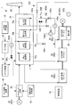
- an integrated gasification combined cycle (IGCC) 1 of the present embodiment includes a main fuel supply unit 10, a gasification furnace 20, a gas cooler 30, Gas purification equipment 40, gas turbine equipment 50, auxiliary fuel supply section (gas supply section) 60, exhaust heat recovery boiler 70, steam turbine equipment 80, generator 90, circulation system section 100, and control device CU.
- the main fuel supply unit 10 is a device that pulverizes coal, which is a solid carbonaceous fuel, using a coal mill (not shown) to generate pulverized coal, and supplies the pulverized coal to the gasifier 20.
- the pulverized coal produced by the main fuel supply unit 10 is supplied to the gasification furnace 20 by being conveyed by nitrogen gas supplied from an air separation device (not shown).
- the gasification furnace 20 is an apparatus that generates flammable gas by gasifying the pulverized coal supplied from the main fuel supply unit 10 with a gasifying agent that is an oxygen-containing gas.
- a gasifying agent that is an oxygen-containing gas.
- the gasification furnace 20 supplies the generated combustible gas to the gas cooler 30.
- the gasification furnace 20 constitutes a gasification furnace facility together with the gas cooler 30.
- oxygen-containing gas oxygen-containing air or oxygen gas generated by an air separation device (not shown) is used.
- the gas cooler 30 is a heat exchanger that generates steam from the cooling water by heat exchange between the combustible gas supplied from the gasification furnace 20 and the cooling water.
- the gas cooler 30 generates steam by heat exchange between the cooling water supplied from the second medium pressure economizer 70b of the exhaust heat recovery boiler 70 and the combustible gas, and supplies the generated steam to the high pressure steam turbine 80a. To do.
- the combustible gas heat-recovered by the gas cooler 30 is guided to the gas purification facility 40 after char is recovered by a char recovery device (not shown).
- the gas purification facility 40 is a facility that purifies the combustible gas from which the char has been separated and removed by the char recovery device, removes impurities such as sulfur, and purifies a gas having a property suitable as a fuel gas for the gas turbine facility 50. .
- the combustible gas purified by the gas purification facility 40 is supplied to a combustor (not shown) of the gas turbine facility 50.
- the gas turbine equipment 50 includes a combustor (not shown), a compressor (not shown), and a gas turbine (not shown).
- the combustor burns the combustible gas supplied from the gas purification facility 40 using the compressed air compressed by the compressor.
- high-temperature and high-pressure combustion gas is generated and supplied from the combustor to the gas turbine.
- the high-temperature and high-pressure combustion gas works to drive the gas turbine, and the high-temperature combustion exhaust gas is discharged.
- the rotating shaft output of the gas turbine is used as a drive source for the generator 90a and the compressor.
- the auxiliary fuel supply unit (gas supply unit) 60 combusts the gas turbine equipment 50 when pulverized coal is not supplied from the main fuel supply unit 10 to the gasification furnace 20 and no combustible gas is generated by the gasification furnace 20.
- This is a device for supplying auxiliary fuel, which is a sex gas.
- the control unit CU controls the auxiliary fuel supply unit 60 to supply auxiliary fuel from the auxiliary fuel supply unit 60.
- the auxiliary fuel for example, a hydrocarbon gas such as natural gas can be used. In addition to the hydrocarbon gas, various flammable gases can be used.
- the exhaust heat recovery boiler 70 is a facility that recovers heat stored in the high-temperature combustion exhaust gas discharged from the gas turbine facility 50 to generate steam.
- the exhaust heat recovery boiler 70 generates steam by heat exchange between the combustion exhaust gas and water, and supplies the generated steam to the steam turbine facility 80.
- the exhaust heat recovery boiler 70 discharges the combustion exhaust gas whose temperature has been lowered by heat exchange with water from the chimney 95 to the atmosphere after performing a necessary treatment.
- the exhaust heat recovery boiler 70 includes a plurality of heat exchangers for exchanging heat between the high-temperature combustion exhaust gas discharged from the gas turbine equipment 50 and cooling water or steam.
- the plurality of heat exchangers are a first medium pressure economizer 70a, a second medium pressure economizer 70b, an intermediate pressure evaporator 70c, and a high pressure evaporator 70d from the downstream side to the upstream side in the flow direction of the combustion exhaust gas. Are arranged in the order.
- the steam turbine facility 80 is a facility that operates with steam supplied from the exhaust heat recovery boiler 70 as a drive source and rotates a rotating shaft to which the generator 90b is connected.
- the generator 90b generates power using the rotational power generated by the rotation of the rotating shaft.
- the steam turbine facility 80 includes a high-pressure steam turbine 80a, an intermediate-pressure steam turbine 80b, and a low-pressure steam turbine 80c.
- the circulation system unit 100 connects various devices that circulate the cooling water and the steam from which the cooling water has evaporated between the gas cooler 30, the exhaust heat recovery boiler 70, and the steam turbine facility 80, and these devices.
- the circulation system unit 100 includes an intermediate-pressure feed water pump 100a, a high-pressure feed water pump 100b, a circulation pump 100c, a control valve 100d, and switching valves 100e, 100f, 100g, 100h, 100i, and 100j. Further, the circulation system unit 100 includes a brackish water separator 100k and a check valve 100l.
- the medium-pressure feed water pump 100a is a pump that feeds the cooling water stored in the condenser 96 that cools the low-pressure steam worked by the low-pressure steam turbine 80c.
- the high-pressure feed water pump 100b is a pump that feeds cooling water discharged from the second medium-pressure economizer 70b to the medium-pressure evaporator 70c, the high-pressure evaporator 70d, and the gas cooler 30.
- the circulation pump 100c is a pump that supplies cooling water from which steam has been separated by the brackish water separator 100k to the first medium pressure economizer 70a.
- the brackish water separator 100k is an apparatus that separates the cooling water heated by the first medium pressure economizer 70a and depressurized by the switching valve 100g into steam and drain water.
- the steam separated by the brackish water separator 100k is supplied to the low-pressure steam turbine 80c.
- the drain water separated by the brackish water separator 100k is supplied to the first medium pressure economizer 70a.
- the control valve 100d is a valve for supplying an amount of cooling water corresponding to the steam separated by the brackish water separator 100k to a circulation system that circulates through the first intermediate pressure economizer 70a.
- the check valve 100l is provided on the downstream side of the control valve 100d, and prevents the coolant from flowing back to the control valve 100d.
- the switching valves 100e, 100f, 100g, 100h, 100i, and 100j are provided on the flow path that constitutes the circulation system unit 100, and the first intermediate pressure economizer 70a and the first medium pressure economizer 70a are connected to the circulation system unit 100 by switching the open / close state.
- 2 is a switching valve that can form a plurality of heat exchange systems in which the medium pressure economizer 70b and the gas cooler 30 are associated.
- the control device (control unit) CU is a device that controls each part of the coal gasification combined cycle facility 1.
- the control device CU executes various control operations by reading and executing the control program from a storage unit (not shown) in which a control program for executing the control operation is stored.
- control unit CU performs the operation shown in the flowchart of FIG. 3 to form a heat exchange system for the cooling water depending on whether or not the combustible gas is generated by the gasification furnace 20, and the combustion exhaust gas. Maintains heat recovery efficiency from.
- step S301 the control unit CU determines whether or not the gasifier 20 is generating combustible gas. If YES, the process proceeds to step S302, and if NO, the process proceeds to step S303.
- the control unit CU determines YES when the pulverized coal as the main fuel is supplied from the main fuel supply unit 10 to the gasifier 20. On the other hand, the control unit CU determines NO when the supply of pulverized coal from the main fuel supply unit 10 to the gasifier 20 is stopped due to an abnormality or the like.
- step S302 the control unit CU forms a series heat exchange system by the first medium pressure economizer 70a, the second medium pressure economizer 70b, and the gas cooler 30.
- the switching state of the switching valves 100e, 100f, 100g, 100h, 100i and the regulating valve 100d is controlled.
- the control unit CU closes the switching valves 100e, 100g, 100h, and 100i (black valves in FIG. 1), and opens the switching valve 100f and the control valve 100d (white valves in FIG. 1). Control.
- switching of the switching state of the switching valve 100j is controlled by a water level of a drum (not shown) installed in the gas cooler 30.
- a water level of a drum (not shown) installed in the gas cooler 30.
- the switching valve 100j is opened to maintain the water level. It becomes.
- the combustible gas supplied from the gasification furnace 20 decreases, the water level does not decrease, so the switching valve 100j maintains a flat state.
- the control unit CU has a drive mechanism built in the other switching valve. This is performed by controlling and driving the valve body. Further, for example, when a drive mechanism is not built in another switching valve, whether the control unit CU should open the other switching valve on the display device (not shown) for switching the open / close state of the other switching valve. This is done by displaying an instruction as to whether or not it should be closed. In the latter case, the operator manually switches the open / close state of the other switching valve in accordance with an instruction from the display device.
- step S302 the serial heat exchange system formed by the operation of step S302 will be described with reference to FIG.
- the cooling water pumped by the medium pressure feed water pump 100a is guided to the first medium pressure economizer 70a via the control valve 100d and the check valve 100l.
- the cooling water led to the first medium pressure economizer 70a is heated by heat exchange with the combustion exhaust gas, and then led to the second medium pressure economizer 70b via the switching valve 100f.
- the cooling water led to the second medium pressure economizer 70b is heated by heat exchange with the combustion exhaust gas, and then a part thereof is led to the high-pressure feed water pump 100b and the other part to the medium pressure evaporator 70c. Led.
- the cooling water guided to the intermediate pressure evaporator 70c is heated by heat exchange with the combustion exhaust gas to become steam, and is guided to the intermediate pressure steam turbine 80b.
- a part of the cooling water led to the high-pressure feed water pump 100b is led to the gas cooler 30 via the switching valve 100j, and the other part is led to the high-pressure evaporator 70d.
- the cooling water guided to the high-pressure evaporator 70d is heated by heat exchange with the combustion exhaust gas to become steam, and is guided to the high-pressure steam turbine 80a.
- the cooling water guided to the gas cooler 30 is heated by heat exchange with the combustible gas generated by the gasification furnace 20 to become steam, and the steam is guided to the exhaust heat recovery boiler 70 to be a heat exchanger (illustrated). And is guided to the high-pressure steam turbine 80a.
- the steam guided to the high-pressure steam turbine 80a is used as rotational power by the high-pressure steam turbine 80a.
- the steam whose temperature has decreased due to work in the high-pressure steam turbine 80a is reheated in the exhaust heat recovery boiler 70 and then guided to the intermediate-pressure steam turbine 80b and used as rotational power in the intermediate-pressure steam turbine 80b.
- the steam whose temperature has decreased due to work in the intermediate pressure steam turbine 80b is guided to the low pressure steam turbine 80c and used as rotational power.
- the steam whose temperature has decreased due to work in the low-pressure steam turbine 80 c is cooled and liquefied by the condenser 96 and stored in a storage section (not shown) of the condenser 96.
- the water stored in the storage part of the condenser 96 is led again to the high-pressure feed pump 100b as cooling water.
- the control unit CU when the gasification furnace 20 is generating combustible gas, the control unit CU includes the first medium pressure economizer 70a, the second medium pressure economizer 70b, and the gas cooler 30.
- a series heat exchange system is formed. In this series heat exchange system, heat exchange is performed by the first medium-pressure economizer 70a, the second medium-pressure economizer 70b, and the gas cooler 30, so that the gas cooler 30 has a unit time per unit time.
- the flow rate of the cooling water flowing through the first and second medium pressure economizers 70a, 70b, and 30 is a flow rate corresponding to the amount of heat recovered by the gas cooler 30.
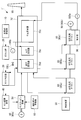
- step S303 in FIG. 3 the control unit CU assists the fuel supplied to the gas turbine equipment 50 from the combustible gas generated by the gasifier 20 because the gasifier 20 does not generate the combustible gas. It switches to the auxiliary fuel which the fuel supply part 60 supplies. The control unit CU transmits the control signal to the auxiliary fuel supply unit 60 so that the auxiliary fuel is supplied from the auxiliary fuel supply unit 60 to the gas turbine equipment 50.
- step S304 the control unit CU controls the individual heat exchange systems (seconds) by the first medium pressure economizer 70a, the second medium pressure economizer 70b, and the gas cooler 30, respectively.
- the switching valves 100e, 100f, 100g, 100h, 100i and the open / close state of the control valve 100d are controlled so as to form a (one heat exchange system, a second heat exchange system).
- the control unit CU controls the switching valve 100f to be closed (black valve in FIG. 2) and the switching valves 100e, 100g, 100h, and 100i to be open (white valve in FIG. 2).
- the open / close state of the regulating valve 100d is appropriately adjusted according to the amount of steam separated by the brackish water separator 100k.
- One of the individual heat exchange systems formed by the operation of step S304 is a first heat exchange system that circulates cooling water through the first medium pressure economizer 70a.
- the other of the individual heat exchange systems is a second heat exchange system that circulates cooling water through the second medium pressure economizer 70b.
- the first heat exchange system and the second heat exchange system are heat exchange systems that circulate cooling water independently of each other.
- the 1st heat exchange system which circulates cooling water to the 1st medium pressure economizer 70a is explained.
- the first heat exchange system guides the cooling water pumped by the circulation pump 100c to the first medium pressure economizer 70a via the switching valve 100h.
- the cooling water led to the first medium pressure economizer 70a is heated by heat exchange with the combustion exhaust gas, and then led to the brackish water separator 100k via the switching valve 100g.
- the cooling water decompressed by the switching valve 100g is guided to the brackish water separator 100k as a cooling medium in which water and steam are mixed.
- the brackish water separator 100k separates the steam from the cooling medium guided from the switching valve 100g and supplies the steam to the low-pressure steam turbine 80c via the switching valve 100i.
- the brackish water separator 100k separates the drain water from the cooling medium guided from the switching valve 100g and supplies it to the circulation pump 100c.
- the circulation pump 100c guides again the drain water (cooling water) separated by the brackish water separator 100k to the first medium pressure economizer 70a via the switching valve 100h.
- the cooling water circulates through the first heat exchange system constituted by the circulation pump 100c, the switching valve 100h, the first medium pressure economizer 70a, the switching valve 100g, and the brackish water separator 100k.
- the steam separated by the brackish water separator 100k is guided to the low-pressure steam turbine 80c that is outside the first heat exchange system. Therefore, the flow rate of the cooling water flowing through the first heat exchange system is reduced by an amount corresponding to the amount of the separated steam. Therefore, in the present embodiment, the control unit CU opens the control valve 100d so that the cooling water corresponding to the amount of steam separated by the brackish water separator 100k flows into the first heat exchange system from the second heat exchange system. Adjust the degree.
- the control unit CU adjusts the opening degree of the control valve 100d so that the liquid level sensor of the brackish water separator 100k has a constant liquid level height.
- the control unit CU increases the opening of the control valve 100d and flows cooling water from the second heat exchange system into the first heat exchange system.
- the control unit CU closes the control valve 100d and the cooling water flows from the second heat exchange system to the first heat exchange system. Do not.
- the 2nd heat exchange system which circulates cooling water to the 2nd medium pressure economizer 70b is explained.
- the cooling water pumped by the medium pressure feed water pump 100a is guided to the second medium pressure economizer 70b via the switching valve 100e.
- the cooling water led to the second medium pressure economizer 70b is heated by heat exchange with the combustion exhaust gas, and then a part thereof is led to the high-pressure feed water pump 100b and the other part to the medium pressure evaporator 70c.
- the cooling water guided to the intermediate pressure evaporator 70c is heated by heat exchange with the combustion exhaust gas to become steam, and is guided to the intermediate pressure steam turbine 80b.
- All of the cooling water led to the high-pressure feed pump 100b is led to the high-pressure evaporator 70d.
- the cooling water guided to the high-pressure evaporator 70d is heated by heat exchange with the combustion exhaust gas to become steam, and is guided to the high-pressure steam turbine 80a.
- the steam guided to the high-pressure steam turbine 80a is used as rotational power for the high-pressure steam turbine 80a.
- the steam whose temperature has decreased due to work in the high-pressure steam turbine 80a is reheated in the exhaust heat recovery boiler 70 and then guided to the intermediate-pressure steam turbine 80b and used as rotational power in the intermediate-pressure steam turbine 80b.
- cooling water when forming the separate heat exchange system which consists of the 1st heat exchange system and the 2nd heat exchange system by operation of Step S304, cooling water will circulate independently in each heat exchange system.
- the amount of cooling water that is not separated as steam by the brackish water separator 100k circulates through the first intermediate pressure economizer 70a to perform heat exchange. Therefore, the flow rate of the cooling water circulating through the first medium pressure economizer 70a per unit time can be increased, and the heat recovery efficiency from the combustion exhaust gas can be increased.
- control unit CU performs the heat exchange of the cooling water depending on whether or not the combustible gas is generated by the gasification furnace 20 by performing the operation shown in the flowchart of FIG.
- a serial or individual circulation system can be formed, and the heat recovery efficiency of the exhaust heat recovery boiler 70 can be maintained.
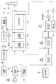
- the coal gasification combined power generation facility 1 ′ of the comparative example of the present embodiment will be described with reference to FIGS. 4 and 5.
- the exhaust heat recovery boiler 70 includes a first medium pressure economizer 70a and a second medium pressure economizer 70b.
- the exhaust heat recovery boiler 70 ′ includes a single medium pressure economizer 70e. 4 and FIG. 5, the same reference numerals as those in FIG. 1 and FIG. 2 are the same as those in FIG. 1 and FIG.
- the temperature of the combustion exhaust gas discharged from the exhaust heat recovery boiler 70 ′ is about 120 ° C.
- the heat recovery efficiency of the exhaust heat recovery boiler 70 is maintained at a high level.
- the temperature of the combustion exhaust gas discharged from the exhaust heat recovery boiler 70 is about 120 ° C.
- the temperature of the combustion exhaust gas discharged from the exhaust heat recovery boiler 70 is also about 120 ° C.
- the predetermined exhaust temperature range of the combustion exhaust gas discharged from the exhaust heat recovery boiler 70 is about 120 ° C.
- the predetermined exhaust temperature range may be, for example, a range of 110 ° C. or higher and 130 ° C. or lower. More preferably, it is in the range of 115 ° C. or more and 125 ° C. or less.
- the comparison between the coal gasification combined power generation facility 1 ′ of the comparative example and the coal gasification combined power generation facility 1 of the present embodiment is performed more than the comparative example.
- the form has higher heat recovery efficiency.
- the amount of heat recovered by the first medium pressure economizer 70a is steam separated by the brackish water separator 100k.
- the brackish water separator 100k To the low pressure steam turbine 80c.
- the gasifier 20 burns the auxiliary fuel.
- the power generation efficiency of the combined coal gasification combined power generation facility 1 of this embodiment is about 2% higher than the power generation efficiency of the combined coal gasification combined power generation facility 1 ′ of the comparative example.
- action and effect which the coal gasification combined cycle power generation equipment 1 of this embodiment show are demonstrated.
- the coal gasification combined power generation facility 1 of the present embodiment when combustible gas is generated by the gasification furnace 20, the combustible gas cooled by the gas cooler 30 is combusted by the gas turbine facility 50 and burned exhaust gas. Then, the exhaust heat recovery boiler 70 is led.
- the first intermediate pressure economizer 70a (first heat exchanger) and the second intermediate pressure economizer 70b (second heat exchanger) of the exhaust heat recovery boiler 70 recover heat from the combustion exhaust gas.
- the gas cooler 30 recovers heat from the combustible gas.
- a series heat exchange system is formed by the first medium-pressure economizer 70a, the second medium-pressure economizer 70b, and the gas cooler 30, so the first medium-pressure economizer 70a and the second medium-pressure economizer 70a Cooling water having a flow rate corresponding to the amount of heat recovered by the pressure-saving charcoal unit 70b and the gas cooler 30 flows through the circulation system unit 100 per unit time.
- auxiliary fuel is supplied from the auxiliary fuel supply unit (gas supply unit) 60 to the gas turbine equipment 50 and is converted into combustion exhaust gas and led to the exhaust heat recovery boiler 70.
- the first intermediate-pressure economizer 70a and the second intermediate-pressure economizer 70b included in the exhaust heat recovery boiler 70 recover heat from the combustion exhaust gas, but heat recovery by the gas cooler 30 is not performed.
- a separate heat exchange system is formed by each of the first medium pressure economizer 70a and the second medium pressure economizer 70b.
- the flow rate of the cooling water flowing through the circulation system unit 100 per unit time is the same as the flow rate of the cooling water flowing through the first heat exchange system forming the first medium pressure economizer 70a per unit time.
- the flow rate is the sum of the flow rate of the cooling water flowing per unit time through the second heat exchange system forming the pressure-saving charcoal unit 70b.
- the flow rate of the cooling water flowing through the circulation system unit 100 per unit time is increased. To do.
- the heat recovery efficiency from the combustion exhaust gas by the exhaust heat recovery boiler 70 can be increased. Therefore, even when auxiliary gas, which is an alternative to the combustible gas generated by the gasification furnace 20, is burned by the gas turbine equipment 50 to generate combustion exhaust gas, heat from the combustion exhaust gas by the exhaust heat recovery boiler 70 is generated.
- the combined coal gasification combined cycle facility 1 capable of maintaining the recovery efficiency can be provided.
- the brackish water separator 100k included in the first heat exchange system formed by the circulation system unit 100 when the gas turbine facility 50 burns auxiliary fuel is Steam is separated from the cooling water heat-exchanged by the 1 medium pressure economizer 70 a and supplied to the steam turbine equipment 80.
- the inflow amount of the cooling water from the 2nd heat exchange system to the 1st heat exchange system is adjusted by control valve 100d according to the supply amount of the steam from brackish water separator 100k to steam turbine equipment 80. Therefore, the flow rate of the cooling water flowing through the first heat exchange system is appropriately maintained.
- the example in which the gasification furnace 20 that gasifies the pulverized coal (pulverized coal) is used as the facility for generating the combustible gas, but may be other modes.
- gasifier facilities that gasify other solid carbonaceous fuels such as thinned wood, waste wood, driftwood, grass, waste, sludge, tires and other biomass fuel as equipment for generating combustible gas May be used.
- the gas turbine equipment 50 and the steam turbine equipment 80 give driving power to the generators 90a and 90b provided exclusively for each, but other modes may be used.
- the gas turbine facility 50 and the steam turbine facility 80 may be configured to provide driving power to the single generator 90.
- 1,1 'Coal gasification combined cycle power generation facility (gasification combined cycle power generation facility) DESCRIPTION OF SYMBOLS 10 Main fuel supply part 20 Gasification furnace 30 Gas cooler 40 Gas purification equipment 50 Gas turbine equipment 60 Auxiliary fuel supply part (gas supply part) 70, 70 'Waste heat recovery boiler 70a First medium pressure economizer (first heat exchanger) 70b Second medium pressure economizer (second heat exchanger) 70c Medium-pressure evaporator 70d High-pressure evaporator 80 Steam turbine equipment 90 Generator 100 Circulation system section 100k Brackish water separator CU Control device
Landscapes
- Engineering & Computer Science (AREA)
- Chemical & Material Sciences (AREA)
- Combustion & Propulsion (AREA)
- Mechanical Engineering (AREA)
- General Engineering & Computer Science (AREA)
- Organic Chemistry (AREA)
- Oil, Petroleum & Natural Gas (AREA)
- Life Sciences & Earth Sciences (AREA)
- Thermal Sciences (AREA)
- Physics & Mathematics (AREA)
- Sustainable Energy (AREA)
- Sustainable Development (AREA)
- Chemical Kinetics & Catalysis (AREA)
- General Chemical & Material Sciences (AREA)
- Engine Equipment That Uses Special Cycles (AREA)
Priority Applications (3)
| Application Number | Priority Date | Filing Date | Title |
|---|---|---|---|
| KR1020167036079A KR101847329B1 (ko) | 2014-08-11 | 2015-06-26 | 가스화 복합 발전 설비, 및 가스화 복합 발전 설비의 운전 방법 |
| CN201580034694.3A CN106662013B (zh) | 2014-08-11 | 2015-06-26 | 煤气化复合发电设备及煤气化复合发电设备的运行方法 |
| US15/320,082 US10415467B2 (en) | 2014-08-11 | 2015-06-26 | Integrated gasification combined cycle and method for operating integrated gasification combined cycle |
Applications Claiming Priority (2)
| Application Number | Priority Date | Filing Date | Title |
|---|---|---|---|
| JP2014163813A JP6433714B2 (ja) | 2014-08-11 | 2014-08-11 | ガス化複合発電設備、およびガス化複合発電設備の運転方法 |
| JP2014-163813 | 2014-08-11 |
Publications (1)
| Publication Number | Publication Date |
|---|---|
| WO2016024447A1 true WO2016024447A1 (ja) | 2016-02-18 |
Family
ID=55304077
Family Applications (1)
| Application Number | Title | Priority Date | Filing Date |
|---|---|---|---|
| PCT/JP2015/068533 Ceased WO2016024447A1 (ja) | 2014-08-11 | 2015-06-26 | ガス化複合発電設備、およびガス化複合発電設備の運転方法 |
Country Status (5)
| Country | Link |
|---|---|
| US (1) | US10415467B2 (enExample) |
| JP (1) | JP6433714B2 (enExample) |
| KR (1) | KR101847329B1 (enExample) |
| CN (1) | CN106662013B (enExample) |
| WO (1) | WO2016024447A1 (enExample) |
Families Citing this family (2)
| Publication number | Priority date | Publication date | Assignee | Title |
|---|---|---|---|---|
| RU2709244C1 (ru) * | 2019-03-21 | 2019-12-17 | Федеральное государственное бюджетное научное учреждение "Федеральный научный агроинженерный центр ВИМ" (ФГБНУ ФНАЦ ВИМ) | Газогенераторная установка для автономного энергообеспечения |
| US20250334061A1 (en) * | 2024-04-29 | 2025-10-30 | Numerical Analysis Inc. | Parallel heat recovery in gas power generation |
Citations (4)
| Publication number | Priority date | Publication date | Assignee | Title |
|---|---|---|---|---|
| JPS61233084A (ja) * | 1985-04-09 | 1986-10-17 | Mitsubishi Heavy Ind Ltd | 石炭ガス化複合発電装置 |
| JPH11100584A (ja) * | 1997-09-25 | 1999-04-13 | Ishikawajima Harima Heavy Ind Co Ltd | ガス化複合発電設備 |
| JP2009197693A (ja) * | 2008-02-21 | 2009-09-03 | Mitsubishi Heavy Ind Ltd | 石炭ガス化複合発電設備 |
| JP2013249745A (ja) * | 2012-05-30 | 2013-12-12 | Mitsubishi Heavy Ind Ltd | ガスタービン冷却システム、石炭ガス化複合発電システム及びガスタービン冷却方法 |
Family Cites Families (10)
| Publication number | Priority date | Publication date | Assignee | Title |
|---|---|---|---|---|
| US4099374A (en) * | 1976-04-15 | 1978-07-11 | Westinghouse Electric Corp. | Gasifier-combined cycle plant |
| CN1007639B (zh) * | 1985-07-19 | 1990-04-18 | 西门子股份有限公司 | 组合式燃气-蒸汽轮机发电站 |
| EP0523466B1 (de) * | 1991-07-17 | 1995-10-04 | Siemens Aktiengesellschaft | Verfahren zum Betreiben einer Gas- und Dampfturbinenanlage und Anlage zur Durchführung des Verfahrens |
| DE59205446D1 (de) * | 1991-07-17 | 1996-04-04 | Siemens Ag | Verfahren zum Betreiben einer Gas- und Dampfturbinenanlage und Anlage zur Durchführung des Verfahrens |
| US6216436B1 (en) * | 1998-10-15 | 2001-04-17 | General Electric Co. | Integrated gasification combined cycle power plant with kalina bottoming cycle |
| JP2001173411A (ja) | 1999-12-20 | 2001-06-26 | Toshiba Corp | ガス化コンバインドサイクル発電プラント |
| EP1655467A1 (en) | 2004-11-03 | 2006-05-10 | Nuon Tecno B.V. | Power generation system |
| CN101663376B (zh) * | 2007-02-12 | 2013-06-12 | 沙索技术有限公司 | 联合进行发电和产生烃 |
| US9163827B2 (en) * | 2012-11-01 | 2015-10-20 | General Electric Company | System and method for using boiler feedwater |
| US20140175803A1 (en) * | 2012-12-26 | 2014-06-26 | General Electric Company | Biomass conversion reactor power generation system and method |
-
2014
- 2014-08-11 JP JP2014163813A patent/JP6433714B2/ja active Active
-
2015
- 2015-06-26 US US15/320,082 patent/US10415467B2/en active Active
- 2015-06-26 KR KR1020167036079A patent/KR101847329B1/ko not_active Expired - Fee Related
- 2015-06-26 CN CN201580034694.3A patent/CN106662013B/zh active Active
- 2015-06-26 WO PCT/JP2015/068533 patent/WO2016024447A1/ja not_active Ceased
Patent Citations (4)
| Publication number | Priority date | Publication date | Assignee | Title |
|---|---|---|---|---|
| JPS61233084A (ja) * | 1985-04-09 | 1986-10-17 | Mitsubishi Heavy Ind Ltd | 石炭ガス化複合発電装置 |
| JPH11100584A (ja) * | 1997-09-25 | 1999-04-13 | Ishikawajima Harima Heavy Ind Co Ltd | ガス化複合発電設備 |
| JP2009197693A (ja) * | 2008-02-21 | 2009-09-03 | Mitsubishi Heavy Ind Ltd | 石炭ガス化複合発電設備 |
| JP2013249745A (ja) * | 2012-05-30 | 2013-12-12 | Mitsubishi Heavy Ind Ltd | ガスタービン冷却システム、石炭ガス化複合発電システム及びガスタービン冷却方法 |
Also Published As
| Publication number | Publication date |
|---|---|
| US20170138258A1 (en) | 2017-05-18 |
| US10415467B2 (en) | 2019-09-17 |
| KR101847329B1 (ko) | 2018-04-09 |
| CN106662013B (zh) | 2018-07-27 |
| JP2016037951A (ja) | 2016-03-22 |
| JP6433714B2 (ja) | 2018-12-05 |
| CN106662013A (zh) | 2017-05-10 |
| KR20170012392A (ko) | 2017-02-02 |
Similar Documents
| Publication | Publication Date | Title |
|---|---|---|
| Ryzhkov et al. | Technological solutions for an advanced IGCC plant | |
| US8091369B2 (en) | Method and apparatus for generating electrical power | |
| JP5840024B2 (ja) | 湿潤燃料を用いて複合発電を行うプラント及びその燃料乾燥方法 | |
| JP2870232B2 (ja) | 石炭ガス化発電プラント | |
| JP6433714B2 (ja) | ガス化複合発電設備、およびガス化複合発電設備の運転方法 | |
| KR19990072003A (ko) | 가스화기 및 파워 플랜트 | |
| JP2006009574A (ja) | 火力発電プラント | |
| JP6890982B2 (ja) | ガス化炉設備、ガス化複合発電設備及びガス化炉設備の起動方法 | |
| US11415078B2 (en) | Combined power generation plant and combined power generation plant control method | |
| JP6004953B2 (ja) | ガス化炉及びガス化炉の運転方法 | |
| JP2019027317A (ja) | ガス化複合発電設備及びその運転方法 | |
| WO2017154982A1 (ja) | 炭素含有原料ガス化システム及びその酸化剤分配比設定方法 | |
| JP2016037951A5 (enExample) | ||
| JP5461299B2 (ja) | ガス化発電プラント | |
| WO2020066459A1 (ja) | ガスタービン装置、ガスタービン設備およびガス化設備ならびにガスタービン装置の運転方法 | |
| JP7720682B2 (ja) | 排熱回収ボイラ、蒸気タービン設備及びガス化設備 | |
| JP7334092B2 (ja) | ガス化複合発電設備及びその運転方法 | |
| JP2013249745A (ja) | ガスタービン冷却システム、石炭ガス化複合発電システム及びガスタービン冷却方法 | |
| JP2024114364A (ja) | 複合発電プラント及び複合発電プラントの運転方法 | |
| Long III et al. | Development and Analysis of an Integrated Mild-Partial Gasification Combined (IMPGC) Cycle: Part 2—Comparison With Other Power Generation Systems | |
| JP2016037593A (ja) | ガス化炉設備、ガス化複合発電設備、およびガス化炉設備の制御方法 | |
| JP2021054895A (ja) | ガス化設備及びこれを備えたガス化複合発電設備 | |
| JP2001090550A (ja) | ガス化複合サイクル発電プラント | |
| JPS61241394A (ja) | 石炭ガス化複合発電装置 |
Legal Events
| Date | Code | Title | Description |
|---|---|---|---|
| 121 | Ep: the epo has been informed by wipo that ep was designated in this application |
Ref document number: 15831527 Country of ref document: EP Kind code of ref document: A1 |
|
| WWE | Wipo information: entry into national phase |
Ref document number: 15320082 Country of ref document: US |
|
| WWE | Wipo information: entry into national phase |
Ref document number: 1020167036079 Country of ref document: KR |
|
| NENP | Non-entry into the national phase |
Ref country code: DE |
|
| 122 | Ep: pct application non-entry in european phase |
Ref document number: 15831527 Country of ref document: EP Kind code of ref document: A1 |