WO2016017160A1 - Carbonitrided bearing member - Google Patents
Carbonitrided bearing member Download PDFInfo
- Publication number
- WO2016017160A1 WO2016017160A1 PCT/JP2015/003797 JP2015003797W WO2016017160A1 WO 2016017160 A1 WO2016017160 A1 WO 2016017160A1 JP 2015003797 W JP2015003797 W JP 2015003797W WO 2016017160 A1 WO2016017160 A1 WO 2016017160A1
- Authority
- WO
- WIPO (PCT)
- Prior art keywords
- concentration
- steel
- content
- carbonitriding
- test
- Prior art date
Links
Images


Classifications
-
- C—CHEMISTRY; METALLURGY
- C22—METALLURGY; FERROUS OR NON-FERROUS ALLOYS; TREATMENT OF ALLOYS OR NON-FERROUS METALS
- C22C—ALLOYS
- C22C38/00—Ferrous alloys, e.g. steel alloys
- C22C38/18—Ferrous alloys, e.g. steel alloys containing chromium
- C22C38/32—Ferrous alloys, e.g. steel alloys containing chromium with boron
-
- C—CHEMISTRY; METALLURGY
- C21—METALLURGY OF IRON
- C21D—MODIFYING THE PHYSICAL STRUCTURE OF FERROUS METALS; GENERAL DEVICES FOR HEAT TREATMENT OF FERROUS OR NON-FERROUS METALS OR ALLOYS; MAKING METAL MALLEABLE, e.g. BY DECARBURISATION OR TEMPERING
- C21D1/00—General methods or devices for heat treatment, e.g. annealing, hardening, quenching or tempering
- C21D1/06—Surface hardening
-
- C—CHEMISTRY; METALLURGY
- C21—METALLURGY OF IRON
- C21D—MODIFYING THE PHYSICAL STRUCTURE OF FERROUS METALS; GENERAL DEVICES FOR HEAT TREATMENT OF FERROUS OR NON-FERROUS METALS OR ALLOYS; MAKING METAL MALLEABLE, e.g. BY DECARBURISATION OR TEMPERING
- C21D6/00—Heat treatment of ferrous alloys
- C21D6/002—Heat treatment of ferrous alloys containing Cr
-
- C—CHEMISTRY; METALLURGY
- C21—METALLURGY OF IRON
- C21D—MODIFYING THE PHYSICAL STRUCTURE OF FERROUS METALS; GENERAL DEVICES FOR HEAT TREATMENT OF FERROUS OR NON-FERROUS METALS OR ALLOYS; MAKING METAL MALLEABLE, e.g. BY DECARBURISATION OR TEMPERING
- C21D6/00—Heat treatment of ferrous alloys
- C21D6/008—Heat treatment of ferrous alloys containing Si
-
- C—CHEMISTRY; METALLURGY
- C21—METALLURGY OF IRON
- C21D—MODIFYING THE PHYSICAL STRUCTURE OF FERROUS METALS; GENERAL DEVICES FOR HEAT TREATMENT OF FERROUS OR NON-FERROUS METALS OR ALLOYS; MAKING METAL MALLEABLE, e.g. BY DECARBURISATION OR TEMPERING
- C21D6/00—Heat treatment of ferrous alloys
- C21D6/02—Hardening by precipitation
-
- C—CHEMISTRY; METALLURGY
- C21—METALLURGY OF IRON
- C21D—MODIFYING THE PHYSICAL STRUCTURE OF FERROUS METALS; GENERAL DEVICES FOR HEAT TREATMENT OF FERROUS OR NON-FERROUS METALS OR ALLOYS; MAKING METAL MALLEABLE, e.g. BY DECARBURISATION OR TEMPERING
- C21D9/00—Heat treatment, e.g. annealing, hardening, quenching or tempering, adapted for particular articles; Furnaces therefor
- C21D9/40—Heat treatment, e.g. annealing, hardening, quenching or tempering, adapted for particular articles; Furnaces therefor for rings; for bearing races
-
- C—CHEMISTRY; METALLURGY
- C22—METALLURGY; FERROUS OR NON-FERROUS ALLOYS; TREATMENT OF ALLOYS OR NON-FERROUS METALS
- C22C—ALLOYS
- C22C38/00—Ferrous alloys, e.g. steel alloys
- C22C38/001—Ferrous alloys, e.g. steel alloys containing N
-
- C—CHEMISTRY; METALLURGY
- C22—METALLURGY; FERROUS OR NON-FERROUS ALLOYS; TREATMENT OF ALLOYS OR NON-FERROUS METALS
- C22C—ALLOYS
- C22C38/00—Ferrous alloys, e.g. steel alloys
- C22C38/002—Ferrous alloys, e.g. steel alloys containing In, Mg, or other elements not provided for in one single group C22C38/001 - C22C38/60
-
- C—CHEMISTRY; METALLURGY
- C22—METALLURGY; FERROUS OR NON-FERROUS ALLOYS; TREATMENT OF ALLOYS OR NON-FERROUS METALS
- C22C—ALLOYS
- C22C38/00—Ferrous alloys, e.g. steel alloys
- C22C38/02—Ferrous alloys, e.g. steel alloys containing silicon
-
- C—CHEMISTRY; METALLURGY
- C22—METALLURGY; FERROUS OR NON-FERROUS ALLOYS; TREATMENT OF ALLOYS OR NON-FERROUS METALS
- C22C—ALLOYS
- C22C38/00—Ferrous alloys, e.g. steel alloys
- C22C38/04—Ferrous alloys, e.g. steel alloys containing manganese
-
- C—CHEMISTRY; METALLURGY
- C22—METALLURGY; FERROUS OR NON-FERROUS ALLOYS; TREATMENT OF ALLOYS OR NON-FERROUS METALS
- C22C—ALLOYS
- C22C38/00—Ferrous alloys, e.g. steel alloys
- C22C38/06—Ferrous alloys, e.g. steel alloys containing aluminium
-
- C—CHEMISTRY; METALLURGY
- C22—METALLURGY; FERROUS OR NON-FERROUS ALLOYS; TREATMENT OF ALLOYS OR NON-FERROUS METALS
- C22C—ALLOYS
- C22C38/00—Ferrous alloys, e.g. steel alloys
- C22C38/12—Ferrous alloys, e.g. steel alloys containing tungsten, tantalum, molybdenum, vanadium, or niobium
-
- C—CHEMISTRY; METALLURGY
- C22—METALLURGY; FERROUS OR NON-FERROUS ALLOYS; TREATMENT OF ALLOYS OR NON-FERROUS METALS
- C22C—ALLOYS
- C22C38/00—Ferrous alloys, e.g. steel alloys
- C22C38/18—Ferrous alloys, e.g. steel alloys containing chromium
- C22C38/22—Ferrous alloys, e.g. steel alloys containing chromium with molybdenum or tungsten
-
- C—CHEMISTRY; METALLURGY
- C22—METALLURGY; FERROUS OR NON-FERROUS ALLOYS; TREATMENT OF ALLOYS OR NON-FERROUS METALS
- C22C—ALLOYS
- C22C38/00—Ferrous alloys, e.g. steel alloys
- C22C38/18—Ferrous alloys, e.g. steel alloys containing chromium
- C22C38/24—Ferrous alloys, e.g. steel alloys containing chromium with vanadium
-
- C—CHEMISTRY; METALLURGY
- C22—METALLURGY; FERROUS OR NON-FERROUS ALLOYS; TREATMENT OF ALLOYS OR NON-FERROUS METALS
- C22C—ALLOYS
- C22C38/00—Ferrous alloys, e.g. steel alloys
- C22C38/18—Ferrous alloys, e.g. steel alloys containing chromium
- C22C38/26—Ferrous alloys, e.g. steel alloys containing chromium with niobium or tantalum
-
- C—CHEMISTRY; METALLURGY
- C22—METALLURGY; FERROUS OR NON-FERROUS ALLOYS; TREATMENT OF ALLOYS OR NON-FERROUS METALS
- C22C—ALLOYS
- C22C38/00—Ferrous alloys, e.g. steel alloys
- C22C38/18—Ferrous alloys, e.g. steel alloys containing chromium
- C22C38/28—Ferrous alloys, e.g. steel alloys containing chromium with titanium or zirconium
-
- C—CHEMISTRY; METALLURGY
- C22—METALLURGY; FERROUS OR NON-FERROUS ALLOYS; TREATMENT OF ALLOYS OR NON-FERROUS METALS
- C22C—ALLOYS
- C22C38/00—Ferrous alloys, e.g. steel alloys
- C22C38/18—Ferrous alloys, e.g. steel alloys containing chromium
- C22C38/40—Ferrous alloys, e.g. steel alloys containing chromium with nickel
- C22C38/54—Ferrous alloys, e.g. steel alloys containing chromium with nickel with boron
-
- C—CHEMISTRY; METALLURGY
- C23—COATING METALLIC MATERIAL; COATING MATERIAL WITH METALLIC MATERIAL; CHEMICAL SURFACE TREATMENT; DIFFUSION TREATMENT OF METALLIC MATERIAL; COATING BY VACUUM EVAPORATION, BY SPUTTERING, BY ION IMPLANTATION OR BY CHEMICAL VAPOUR DEPOSITION, IN GENERAL; INHIBITING CORROSION OF METALLIC MATERIAL OR INCRUSTATION IN GENERAL
- C23C—COATING METALLIC MATERIAL; COATING MATERIAL WITH METALLIC MATERIAL; SURFACE TREATMENT OF METALLIC MATERIAL BY DIFFUSION INTO THE SURFACE, BY CHEMICAL CONVERSION OR SUBSTITUTION; COATING BY VACUUM EVAPORATION, BY SPUTTERING, BY ION IMPLANTATION OR BY CHEMICAL VAPOUR DEPOSITION, IN GENERAL
- C23C8/00—Solid state diffusion of only non-metal elements into metallic material surfaces; Chemical surface treatment of metallic material by reaction of the surface with a reactive gas, leaving reaction products of surface material in the coating, e.g. conversion coatings, passivation of metals
- C23C8/06—Solid state diffusion of only non-metal elements into metallic material surfaces; Chemical surface treatment of metallic material by reaction of the surface with a reactive gas, leaving reaction products of surface material in the coating, e.g. conversion coatings, passivation of metals using gases
- C23C8/28—Solid state diffusion of only non-metal elements into metallic material surfaces; Chemical surface treatment of metallic material by reaction of the surface with a reactive gas, leaving reaction products of surface material in the coating, e.g. conversion coatings, passivation of metals using gases more than one element being applied in one step
- C23C8/30—Carbo-nitriding
- C23C8/32—Carbo-nitriding of ferrous surfaces
-
- C—CHEMISTRY; METALLURGY
- C23—COATING METALLIC MATERIAL; COATING MATERIAL WITH METALLIC MATERIAL; CHEMICAL SURFACE TREATMENT; DIFFUSION TREATMENT OF METALLIC MATERIAL; COATING BY VACUUM EVAPORATION, BY SPUTTERING, BY ION IMPLANTATION OR BY CHEMICAL VAPOUR DEPOSITION, IN GENERAL; INHIBITING CORROSION OF METALLIC MATERIAL OR INCRUSTATION IN GENERAL
- C23C—COATING METALLIC MATERIAL; COATING MATERIAL WITH METALLIC MATERIAL; SURFACE TREATMENT OF METALLIC MATERIAL BY DIFFUSION INTO THE SURFACE, BY CHEMICAL CONVERSION OR SUBSTITUTION; COATING BY VACUUM EVAPORATION, BY SPUTTERING, BY ION IMPLANTATION OR BY CHEMICAL VAPOUR DEPOSITION, IN GENERAL
- C23C8/00—Solid state diffusion of only non-metal elements into metallic material surfaces; Chemical surface treatment of metallic material by reaction of the surface with a reactive gas, leaving reaction products of surface material in the coating, e.g. conversion coatings, passivation of metals
- C23C8/80—After-treatment
-
- F—MECHANICAL ENGINEERING; LIGHTING; HEATING; WEAPONS; BLASTING
- F16—ENGINEERING ELEMENTS AND UNITS; GENERAL MEASURES FOR PRODUCING AND MAINTAINING EFFECTIVE FUNCTIONING OF MACHINES OR INSTALLATIONS; THERMAL INSULATION IN GENERAL
- F16C—SHAFTS; FLEXIBLE SHAFTS; ELEMENTS OR CRANKSHAFT MECHANISMS; ROTARY BODIES OTHER THAN GEARING ELEMENTS; BEARINGS
- F16C33/00—Parts of bearings; Special methods for making bearings or parts thereof
- F16C33/30—Parts of ball or roller bearings
- F16C33/58—Raceways; Race rings
- F16C33/62—Selection of substances
-
- F—MECHANICAL ENGINEERING; LIGHTING; HEATING; WEAPONS; BLASTING
- F16—ENGINEERING ELEMENTS AND UNITS; GENERAL MEASURES FOR PRODUCING AND MAINTAINING EFFECTIVE FUNCTIONING OF MACHINES OR INSTALLATIONS; THERMAL INSULATION IN GENERAL
- F16C—SHAFTS; FLEXIBLE SHAFTS; ELEMENTS OR CRANKSHAFT MECHANISMS; ROTARY BODIES OTHER THAN GEARING ELEMENTS; BEARINGS
- F16C2204/00—Metallic materials; Alloys
- F16C2204/60—Ferrous alloys, e.g. steel alloys
- F16C2204/66—High carbon steel, i.e. carbon content above 0.8 wt%, e.g. through-hardenable steel
-
- F—MECHANICAL ENGINEERING; LIGHTING; HEATING; WEAPONS; BLASTING
- F16—ENGINEERING ELEMENTS AND UNITS; GENERAL MEASURES FOR PRODUCING AND MAINTAINING EFFECTIVE FUNCTIONING OF MACHINES OR INSTALLATIONS; THERMAL INSULATION IN GENERAL
- F16C—SHAFTS; FLEXIBLE SHAFTS; ELEMENTS OR CRANKSHAFT MECHANISMS; ROTARY BODIES OTHER THAN GEARING ELEMENTS; BEARINGS
- F16C2204/00—Metallic materials; Alloys
- F16C2204/60—Ferrous alloys, e.g. steel alloys
- F16C2204/70—Ferrous alloys, e.g. steel alloys with chromium as the next major constituent
-
- F—MECHANICAL ENGINEERING; LIGHTING; HEATING; WEAPONS; BLASTING
- F16—ENGINEERING ELEMENTS AND UNITS; GENERAL MEASURES FOR PRODUCING AND MAINTAINING EFFECTIVE FUNCTIONING OF MACHINES OR INSTALLATIONS; THERMAL INSULATION IN GENERAL
- F16C—SHAFTS; FLEXIBLE SHAFTS; ELEMENTS OR CRANKSHAFT MECHANISMS; ROTARY BODIES OTHER THAN GEARING ELEMENTS; BEARINGS
- F16C2223/00—Surface treatments; Hardening; Coating
- F16C2223/10—Hardening, e.g. carburizing, carbo-nitriding
- F16C2223/16—Hardening, e.g. carburizing, carbo-nitriding with carbo-nitriding
-
- F—MECHANICAL ENGINEERING; LIGHTING; HEATING; WEAPONS; BLASTING
- F16—ENGINEERING ELEMENTS AND UNITS; GENERAL MEASURES FOR PRODUCING AND MAINTAINING EFFECTIVE FUNCTIONING OF MACHINES OR INSTALLATIONS; THERMAL INSULATION IN GENERAL
- F16C—SHAFTS; FLEXIBLE SHAFTS; ELEMENTS OR CRANKSHAFT MECHANISMS; ROTARY BODIES OTHER THAN GEARING ELEMENTS; BEARINGS
- F16C2240/00—Specified values or numerical ranges of parameters; Relations between them
- F16C2240/90—Surface areas
Definitions
- the present invention relates to a bearing part, and more particularly, to a carbonitrided bearing part that has been subjected to carbonitriding and tempering.
- Steel materials for medium and large bearing parts include bearing steels represented by SUJ3 and SUJ5 specified in JIS G 4805 (2008), and SNCM systems represented by SNCM815 specified in JIS G 4053 (2008). And with case-hardened steel.
- An example of the manufacturing process of bearing parts using these steels is as follows. The steel material is subjected to hot working (for example, hot forging) and cutting to produce an intermediate product having a predetermined shape. The intermediate product is heat-treated to adjust to a predetermined hardness and microstructure. The heat treatment is quenching and tempering in the case of bearing steel, and carburizing treatment (carburizing and tempering) in the case of case-hardened steel.
- a bearing part is manufactured by the above process.
- ⁇ Some bearing parts may require excellent wear resistance and surface-origination life.
- a carbonitriding process (carbonitriding and quenching and tempering) is performed instead of the carburizing process as the heat treatment in the bearing component manufacturing process.
- the carbonitriding process increases the carbon concentration and nitrogen concentration of the surface layer of the steel material to make the steel surface layer hard.
- Patent Document 1 Japanese Unexamined Patent Publication No. 8-49057
- Patent Document 2 Japanese Unexamined Patent Application Publication No. 2008-280583
- Patent Document 3 Japanese Unexamined Patent Application Publication No. 11-12684
- Patent Document 4 JP-A-6-287712
- Patent Document 1 carburizing treatment or carbonitriding treatment is performed on a steel material containing a large amount of V to precipitate V carbide on the surface layer. It is described that a rolling bearing has excellent wear resistance characteristics due to this V carbide.
- the V content in the steel of Patent Document 1 is as high as 0.8 to 2.0%. Therefore, when carbonitriding is performed, coarse V carbide and V carbonitride may be generated, and the toughness of the bearing member may be significantly reduced.
- Patent Document 2 The case-hardened steel disclosed in Patent Document 2 focuses on hydrogen embrittlement with respect to bearing life, finely disperses V-based carbides, and enhances the effect of hydrogen trap sites. Thereby, it is described that the surface fatigue strength is increased.
- Patent Document 4 contains a large amount of retained austenite in the surface layer by performing carbonitriding and quenching. As a result, it is described that the surface origin peeling life is increased.
- Patent Document 4 contains 0.5% or more of expensive Ni. Therefore, when applied to medium-sized and large-sized bearing parts, the manufacturing cost increases.
- JP-A-8-49057 JP 2008-280583 A Japanese Patent Laid-Open No. 11-12684 JP-A-6-287712
- An object of the present invention is to provide a carbonitrided bearing component that has high toughness, excellent wear resistance, and excellent surface separation life even if it does not contain Ni.
- the carbonitrided bearing component of the present embodiment is, in mass%, C: 0.15 to 0.45%, Si: 0.50% or less, Mn: 0.40 to 1.50%, P: 0.015%
- Nb 0 to 0.10%
- Ti 0 to 0.10%
- the balance is composed of Fe and impurities, and has a chemical composition satisfying the formulas (1) and (2).
- the C concentration on the surface is 0.7 to 1.2%
- the N concentration is 0.15 to 0.6%
- the Rockwell hardness HRC on the surface is 58 to 65. 1.20 ⁇ 0.4Cr + 0.4Mo + 4.5V ⁇ 2.60 (1) 2.7C + 0.4Si + Mn + 0.8Cr + Mo + V> 2.20 (2)
- the carbonitrided bearing component of the present embodiment is excellent in toughness, wear resistance, and surface origin peeling life.
- FIG. 1 is a diagram showing a heat pattern of quenching and tempering for a test piece for a hardenability evaluation test and a toughness evaluation test in Example 1.
- FIG. FIG. 2 is a side view and a cross-sectional view of an intermediate product of a small roller test piece used in the roller pitching test.
- 3 is a side view and a cross-sectional view of a small roller test piece manufactured from the intermediate product of FIG.
- FIG. 4 is a diagram showing a heat pattern of carbonitriding and quenching and tempering applied in the second embodiment.
- FIG. 5 is a diagram showing a heat pattern for carbonitriding and tempering and tempering different from those in FIG. 4.
- the present inventors investigated and examined the effects of steel components, particularly C, Si, Cr, Mo, V, on the wear resistance, surface-origination peeling life, hardenability, and toughness of carbonitrided bearing parts. As a result, the present inventors obtained the following knowledge.
- V generates carbide and carbonitride (hereinafter referred to as carbonitride). Therefore, if the V content is increased, the wear resistance of the carbonitrided bearing component is increased. However, if the V content is too high, the hot ductility of the steel material is lowered, and cracks are likely to occur during hot working (during hot rolling and hot forging). Furthermore, when coarse carbonitrides etc. exist in steel materials, the toughness of the core part of the bearing component after carbonitriding processing falls. Further, if coarse carbonitrides or the like remain in the bearing component, these coarse precipitates become a stress concentration source. In this case, these coarse precipitates serve as fatigue starting points, and the surface starting point peel life decreases.
- carbonitride carbide and carbonitride
- precipitate nuclei precipitate nuclei
- V, Cr and Mo are contained in combination, the number of precipitation nucleation sites increases, and a large number of carbonitrides and the like are precipitated.
- these carbonitrides remain without being dissolved in the heating step before hot rolling and hot forging, the carbonitrides remaining in the carbonitriding process become coarse. In this case, the surface starting point peeling life is reduced. Therefore, carbonitrides and the like are sufficiently dissolved in the heating step before hot rolling and hot forging.
- the heating temperature may be increased.
- the microstructure crystal grains
- the toughness of the steel material decreases.
- the upper limit of heating temperature is restrict
- the present inventors have found that if the chemical composition of the bearing component (carbonitrided bearing component) satisfies the following formula (1), the surface-origination peeling life is reduced and the toughness is reduced. It was found that the wear resistance can be improved while suppressing the decrease. 1.20 ⁇ 0.4Cr + 0.4Mo + 4.5V ⁇ 2.60 (1) Here, the content (mass%) of the corresponding element is substituted for each element in the formula (1).
- fn1 0.4Cr + 0.4Mo + 4.5V. If fn1 is 1.20 or less, precipitation nucleation sites are insufficient. In this case, precipitation of fine carbonitrides and the like becomes insufficient, and wear resistance decreases. On the other hand, when fn1 is 2.60 or more, wear resistance is increased, but undissolved coarse carbonitrides remain. Therefore, the surface starting point peeling life and toughness are lowered.
- the fracture toughness of steel materials with a structure mainly composed of tempered martensite mainly consists of the strength of the tempered martensite structure, the C content that affects the substructure, the P content that causes grain boundary embrittlement, and the sulfidization in the steel material. The amount of things affects.
- the C content is 0.15% or more.
- the P content is limited to 0.015% or less.
- sulfides not only have fracture toughness, but also have a surface origin and a debonding life. Therefore, the S content is limited to 0.005% or less as described above.
- the carbonitrided bearing component according to the present embodiment completed based on the above knowledge is, in mass%, C: 0.15 to 0.45%, Si: 0.50% or less, Mn: 0.40 to 1.50. %, P: 0.015% or less, S: 0.005% or less, Cr: 0.30 to 2.0%, Mo: 0.10 to 0.35%, V: 0.20 to 0.40% Al: 0.005 to 0.10%, N: 0.030% or less, O: 0.0015% or less, B: 0 to 0.0050%, Nb: 0 to 0.10%, and Ti: It contains 0 to 0.10%, the balance is made of Fe and impurities, and has a chemical composition satisfying the formulas (1) and (2).
- the C concentration on the surface of the carbonitrided bearing component is 0.7 to 1.2%, and the N concentration is 0.15 to 0.6%.
- the Rockwell hardness HRC of the surface of the carbonitrided bearing component is 58-65. 1.20 ⁇ 0.4Cr + 0.4Mo + 4.5V ⁇ 2.60 (1) 2.7C + 0.4Si + Mn + 0.8Cr + Mo + V> 2.20 (2) Here, the content (mass%) of a corresponding element is substituted for each element symbol in the formulas (1) and (2).
- the carbonitrided bearing component may contain B: 0.0003 to 0.0050%, Nb: 0.005 to 0.10%, and Ti: 0.005 to 0.10%. .
- the carbonitrided bearing component is manufactured by performing carbonitriding and tempering and tempering on steel (carbonitriding bearing steel) having the following chemical composition. Therefore, the chemical composition of the carbonitrided bearing component contains the following elements.
- Carbon (C) increases the hardenability of the steel and increases the strength and toughness of the core of the carbonitrided bearing component. C further enhances the surface-origin peeling life of the carbonitrided bearing component. If the C content is too low, these effects cannot be obtained. On the other hand, if the C content is too high, coarse carbides and carbonitrides (carbonitrides and the like) remain even after hot working, and the toughness and surface origin peeling life of the carbonitrided bearing parts are reduced. Therefore, the C content is 0.15 to 0.45%.
- the minimum with preferable C content is 0.22%, More preferably, it is 0.23%.
- the upper limit with preferable C content is 0.42%, More preferably, it is 0.41%.
- Si Silicon
- Si is inevitably contained. Si increases the strength of the steel. Further, Si enhances the surface origin peeling life of the carbonitrided bearing component. However, if the Si content is too high, the hardness of the base material becomes too high, and the tool life during cutting decreases. If the Si content is too high, the toughness and hot workability of the steel material are further reduced. Therefore, the Si content is 0.50% or less.
- the minimum with preferable Si content is 0.01%, More preferably, it is 0.02%, More preferably, it is 0.05%.
- the upper limit with preferable Si content is 0.35%, and when a cold workability is considered, a more preferable upper limit is 0.10%.
- Mn 0.40 to 1.50%
- Manganese (Mn) enhances the hardenability of steel and further increases the surface-origin peeling life of carbonitrided bearing parts. If the Mn content is too low, these effects cannot be obtained. On the other hand, if the Mn content is too high, the hardness of the base material becomes too high, and the tool life during cutting decreases. If the Mn content is too high, the toughness is further reduced, and cracking occurs during quenching. Therefore, the Mn content is 0.40 to 1.50%.
- the minimum with preferable Mn content is 0.45%, More preferably, it is 0.48%.
- the upper limit with preferable Mn content is 1.30%, More preferably, it is 1.00% or less, More preferably, it is 0.75%.
- Phosphorus (P) is an impurity. P segregates at the grain boundaries and reduces the toughness of the carbonitrided bearing parts. Therefore, the P content is 0.015% or less.
- the upper limit of the preferable P content is 0.013%, more preferably 0.010%.
- the P content is preferably as low as possible.
- S 0.005% or less Sulfur (S) is an impurity. S generates sulfides in the steel and reduces the surface origin peeling life of the carbonitrided bearing parts. Therefore, the S content is 0.005% or less. The upper limit of the S content for further increasing the surface origin peeling life is 0.004%, more preferably 0.003%. The S content is preferably as low as possible.
- Chromium (Cr) increases the hardenability of steel and increases the strength of carbonitrided bearing parts. Further, Cr is contained in combination with V and Mo, thereby promoting the formation of fine precipitates during the carbonitriding process (carbonitriding and quenching and tempering) and improving the wear resistance of the carbonitrided bearing part. If the Cr content is too low, these effects cannot be obtained. On the other hand, if the Cr content is too high, the carburizability during the carbonitriding process is reduced. Therefore, the Cr content is 0.30 to 2.0%. The minimum with preferable Cr content is 0.50%, More preferably, it is 0.60%. The upper limit with preferable Cr content is 1.8%, More preferably, it is 1.7%.
- Mo 0.10 to 0.35% Molybdenum (Mo) increases the hardenability of steel, as does Cr. Further, Mo is contained in combination with V and Cr, thereby promoting the formation of fine precipitates during the carbonitriding process and enhancing the wear resistance of the carbonitrided bearing component. If the Mo content is too low, these effects cannot be obtained. On the other hand, if the Mo content is too high, the hot workability and machinability of the steel are lowered, and the production cost is increased. Therefore, the Mo content is 0.10 to 0.35%. The minimum with preferable Mo content is 0.20%, More preferably, it is 0.22%. The upper limit with preferable Mo content is 0.30%, More preferably, it is 0.28%.
- V 0.20 to 0.40% Vanadium (V) enhances the hardenability of steel, as does Cr and Mo. V further combines with C and N to produce fine precipitates (carbonitrides and the like).
- V Vanadium
- Cr Cr
- Mo vanadium
- the wear resistance of the carbonitrided bearing component is improved. If the V content is too low, these effects cannot be obtained.
- the V content is too high, undissolved coarse carbides remain even after hot working, and the toughness and surface origin peeling life of the carbonitrided bearing parts are reduced. Furthermore, the hot workability and machinability of the steel also deteriorate. Therefore, the V content is 0.20 to 0.40%.
- the minimum with preferable V content is 0.21%, More preferably, it is 0.22%.
- the upper limit with preferable V content is 0.38%, More preferably, it is 0.36%.
- Al 0.005 to 0.10%
- Aluminum (Al) deoxidizes steel. If the Al content is too low, this effect cannot be obtained. On the other hand, if the Al content is too high, coarse oxide inclusions remain in the steel, and the surface starting point peeling life of the carbonitrided bearing component is reduced. Therefore, the Al content is 0.005 to 0.10%.
- the minimum with preferable Al content is 0.008%, More preferably, it is 0.010%.
- the upper limit with preferable Al content is 0.050%, More preferably, it is 0.048%.
- the Al content here means the content of total Al (Total Al).
- N 0.030% or less Nitrogen (N) is an impurity. N dissolves in the steel and decreases the hot workability of the steel. Therefore, the N content is 0.030% or less. The upper limit with preferable N content is 0.025%, More preferably, it is 0.020%. The N content is preferably as low as possible.
- Oxygen (O) is an impurity. O combines with other elements in the steel to produce an oxide, which reduces the strength of the steel material. Further, O generates an oxide and promotes the coarsening of MnS, thereby reducing the surface origin peeling life of the carbonitrided bearing component. Therefore, the O content is 0.0015% or less. The upper limit with preferable O content is 0.0013%, More preferably, it is 0.0012%. The O content is preferably as low as possible.
- the balance of the chemical composition of the carbonitrided bearing component according to the present embodiment is composed of Fe and impurities.
- the impurities are mixed from the ore as a raw material, scrap, or the manufacturing environment when the carbonitriding bearing steel is industrially produced, and are included in the carbonitriding bearing component of this embodiment. It means what is allowed as long as it does not adversely affect.
- the chemical composition of the carbonitrided bearing component of this embodiment may further contain one or more selected from the group consisting of B, Nb, and Ti. These elements are optional elements, and all increase the strength of the carbonitrided bearing component.
- B 0 to 0.0050%
- Boron (B) is an optional element and may not be contained. When contained, B increases the hardenability of the steel and increases the strength of the carbonitrided bearing component. B further suppresses the segregation of P and S at the austenite grain boundaries during quenching. However, if the B content is too high, B nitride (BN) is generated and the toughness of the steel is reduced. Therefore, the B content is 0 to 0.0050%.
- the minimum with preferable B content is 0.0003%, More preferably, it is 0.0005%, More preferably, it is 0.0010%.
- the upper limit with preferable B content is 0.0030%, More preferably, it is 0.0025%.
- Niobium (Nb) is an optional element and may not be contained. When contained, Nb combines with C and N in the steel to form carbides, nitrides, and carbonitrides. These precipitates refine crystal grains and enhance the strength of carbonitrided bearing parts by precipitation strengthening. However, if the Nb content is too high, the toughness of the steel decreases. Therefore, the Nb content is 0 to 0.10%.
- the minimum with preferable Nb content is 0.005%, More preferably, it is 0.010%.
- the upper limit with preferable Nb content is 0.080%, More preferably, it is 0.070%.
- Titanium (Ti) is an optional element and may not be contained. When contained, Ti, like Nb, produces carbides, nitrides, and carbonitrides, refines the crystal grains, and increases the strength of the carbonitrided bearing component. However, if the Ti content is too high, the toughness of the steel decreases. Therefore, the Ti content is 0 to 0.10%. The minimum with preferable Ti content is 0.005%, More preferably, it is 0.010%. The upper limit with preferable Ti content is 0.080%, More preferably, it is 0.070%.
- fn1 0.4Cr + 0.4Mo + 4.5V. If fn1 is 1.20 or less, the precipitation nucleation site is insufficient, so that fine carbonitrides and the like are not easily generated. For this reason, the wear resistance of the carbonitrided bearing component is reduced. On the other hand, if fn1 is 2.60 or more, precipitation nucleation sites are sufficient and wear resistance is improved, but undissolved coarse carbonitrides remain in the steel even after hot working. . In this case, during carbonitriding and tempering and tempering, coarse carbonitrides further grow and become coarse.
- the lower limit of fn1 is higher than 1.20, and the upper limit of fn1 is less than 2.60.
- a preferred lower limit of fn1 is 1.22.
- the preferable upper limit of fn1 is 2.58.
- fn2 2.7C + 0.4Si + Mn + 0.8Cr + Mo + V.
- fn2 is an index of the hardenability of the carbonitriding bearing steel and the strength of the carbonitriding bearing component.
- fn2 is 2.20 or less, the hardenability of the steel is too low. In this case, the hardness of the core portion of the carbonitrided bearing component is lowered, and the strength of the carbonitrided bearing component is lowered. Therefore, fn2 exceeds 2.20. In this case, the strength of the carbonitrided bearing component is sufficiently increased.
- the minimum with preferable fn2 is 2.70, More preferably, it is 3.20.
- the carbonitrided bearing component in the present embodiment further has the following characteristics on the surface.
- the C concentration of the surface of the carbonitrided bearing part produced by carbonitriding and tempering is 0.7 to 1.2%. If the C concentration on the surface is too low, the surface hardness becomes too low and the wear resistance is reduced. On the other hand, if the C concentration on the surface is too high, coarse carbonitrides and the like remain, so that the surface starting point peel life decreases. When the C concentration on the surface is 0.7 to 1.2%, the wear resistance and the surface starting point peeling life are excellent.
- a preferable lower limit of the C concentration on the surface is 0.75%, and more preferably 0.80%.
- a preferable upper limit of the C concentration on the surface is 1.1%, more preferably 1.05%, and still more preferably 1.00%.
- the N concentration on the surface of the carbonitrided bearing parts produced by carbonitriding and tempering is 0.15 to 0.6%. If the N concentration on the surface is too low, the amount of retained austenite after carbonitriding and quenching is too small, and the formation of fine carbonitrides is suppressed, so that the wear resistance decreases. On the other hand, if the surface N concentration is too high, an excessive amount of retained austenite is generated. In this case, the hardness of the surface of the carbonitrided bearing component is reduced, and the strength and the surface starting point are reduced. If the N concentration on the surface is 0.15 to 0.6%, the wear resistance and the surface starting point peeling life are excellent. A preferable lower limit of the N concentration on the surface is 0.18%, and more preferably 0.20%. A preferable upper limit of the N concentration on the surface is 0.58%, more preferably 0.56%, and further preferably 0.54%.
- the surface C concentration and N concentration are measured by the following method. Using an electron beam microanalyzer (EPMA), C concentration and N concentration are measured at a pitch of 1.0 ⁇ m from the surface to a depth of 100 ⁇ m at any surface position of the carburized bearing part. The average of the measured C concentration is defined as the surface C concentration (% by mass). Similarly, the average of the measured N concentration is defined as the surface N concentration (mass%).
- EPMA electron beam microanalyzer
- the Rockwell C hardness HRC of the surface of the carbonitrided bearing part produced by carbonitriding and quenching and tempering is 58 to 65. If the surface Rockwell C hardness HRC is less than 58, the wear resistance is lowered, and the surface origin peeling life is also lowered. On the other hand, if the Rockwell C hardness of the surface exceeds 65, the development sensitivity when a minute crack is generated increases, and the surface starting point peels off instead. If the surface Rockwell C hardness is 58 to 65, excellent wear resistance and excellent surface-origination peeling life can be obtained.
- the preferable lower limit of the surface Rockwell C hardness is 58.5, more preferably 59.0.
- the upper limit of the surface Rockwell C hardness is preferably 64.5, more preferably 64.3.
- the Rockwell C hardness HRC of carbonitrided bearing parts is measured by the following method. Any four measurement positions on the surface of the carbonitrided bearing component are specified. At the four specified measurement positions, a Rockwell hardness test using a C scale is performed in accordance with JIS Z2245 (2011). The average of the obtained Rockwell C hardness HRC is defined as the Rockwell C hardness HRC at the surface.
- a molten steel having the above-described chemical composition and satisfying the formulas (1) and (2) is made into a slab by a continuous casting method.
- the molten steel may be made into an ingot (steel ingot) by the ingot-making method.
- a slab or ingot is hot-worked to produce a billet.
- a slab or ingot is made into a steel piece by split rolling.
- a steel slab or cast slab is hot-worked to produce a carbonitriding bearing steel such as a steel bar or wire.
- the hot working may be hot rolling or hot forging (hot forging, etc.). If necessary, the soaking diffusion treatment may be performed on the steel slab or slab before hot rolling.
- You may implement a normalization process and a spheroidizing annealing process with respect to the manufactured carbonitriding bearing steel material as needed.
- the steel material for carbonitriding bearings is manufactured by the above process.
- An intermediate product is manufactured by processing a carbonitrided bearing steel material into a predetermined shape.
- the processing method is, for example, machining.
- the machining is, for example, cutting.
- the produced intermediate product is subjected to carbonitriding and tempering and tempering to produce a carbonitrided bearing part.
- the tempering treatment the carbonitrided and quenched intermediate product is held in a temperature range of 100 to 500 ° C. for a predetermined time.
- the surface C concentration, surface N concentration and surface hardness of the carbonitrided bearing parts are adjusted by controlling the conditions of carbonitriding and quenching and tempering. Specifically, the surface C concentration and the surface N concentration are adjusted by controlling the carbon potential and ammonia concentration in the atmosphere during carbonitriding and quenching.
- the surface C concentration is mainly adjusted by the carbon potential of carbonitriding and quenching, the heating temperature, and the holding time.
- the surface N concentration is mainly adjusted by the ammonia concentration of carbonitriding and quenching, the heating temperature, and the holding time.
- the surface hardness is related to the surface C concentration and the surface N concentration. Specifically, the surface hardness increases as the surface C concentration and the surface N concentration increase. On the other hand, if the surface C concentration and the surface N concentration are lowered, the surface hardness is also lowered. However, if the surface N concentration is too high, the surface hardness decreases due to retained austenite.
- the surface hardness increased by carbonitriding can be reduced by tempering. If the tempering temperature is increased and the holding time at the tempering temperature is increased, the surface hardness decreases. If the tempering temperature is lowered and the holding time at the tempering temperature is shortened, the surface hardness can be maintained high.
- Preferred conditions for carbonitriding are as follows.
- Carbon potential CP in the atmosphere 0.7-1.4 If the carbon potential CP in the atmosphere is too low, the C concentration on the surface of the carbonitrided bearing component will be less than 0.7%. In this case, a sufficient amount of carbonitride cannot be dispersed and wear resistance is reduced. On the other hand, if the carbon potential CP is too high, the surface C concentration exceeds 1.2%. In this case, since coarse carbonitrides and the like remain, the surface starting point peeling life decreases. Therefore, the carbon potential CP is 0.7 to 1.4.
- Ammonia concentration with respect to carburized metamorphic gas flow rate in atmosphere 1 to 6% If the ammonia concentration relative to the carburized metamorphic gas flow rate in the atmosphere is too low, the N concentration on the surface of the carbonitrided bearing component will be less than 0.15%. In this case, a sufficient amount of carbonitride cannot be dispersed and wear resistance is reduced. On the other hand, if the ammonia concentration is too high, the surface N concentration exceeds 0.6%. In this case, since coarse carbonitrides remain, the surface starting point peel life decreases. Therefore, the ammonia concentration is 1-6%.
- Holding temperature during carbonitriding (carbonitriding temperature): 830 to 930 ° C Holding time at the carbonitriding temperature: 3 hours or more If the carbonitriding temperature is too low, the diffusion rate of C and N becomes slow. In this case, the processing time required to obtain a predetermined heat treatment property becomes long, and the production cost increases. On the other hand, if the carbonitriding temperature is too high, ammonia in the atmosphere is decomposed, the amount of N entering the steel material decreases, and the solid solution amount of the invading C and N into the steel material matrix increases. In this case, a sufficient amount of carbonitride cannot be dispersed and wear resistance is reduced. Therefore, the carbonitriding temperature is 830 to 930 ° C.
- the holding time at the carbonitriding temperature is 3 hours or more in order to secure sufficient C concentration and N concentration on the steel surface. Note that C and N diffuse into the steel as the holding time increases. Therefore, the holding time may be increased as necessary.
- Quenching temperature 830-930 ° C Holding time at quenching temperature: within 1 hour If the quenching temperature is too low, sufficient C cannot be dissolved in the steel, and the hardness of the steel decreases. On the other hand, if the quenching temperature is too high, the crystal grains become coarse, and coarse carbonitrides along the crystal grain boundaries are likely to precipitate. In this case, the function as a rolling bearing is reduced. Accordingly, the quenching temperature is 830 to 930 ° C.
- the holding time at the quenching temperature may be longer than the time necessary for the entire intermediate product to reach the predetermined quenching temperature. However, if the holding time at the quenching temperature exceeds 1 hour, the crystal grains become coarse. Therefore, the holding time at the quenching temperature is within 1 hour.
- Preferred conditions for tempering are as follows.
- Tempering temperature 150-200 ° C Holding time at tempering temperature: 0.5 to 4 hours If the tempering temperature is too low, sufficient toughness cannot be obtained. On the other hand, if the tempering temperature is too high, the surface hardness decreases, and the wear resistance of the carbonitrided bearing component decreases. Accordingly, the tempering temperature is 150 to 200 ° C.
- the holding time at the tempering temperature is 0.5 to 4 hours.
- Molten steel having various chemical compositions shown in Table 1 was produced using a converter.
- Bloom was produced by continuously casting molten steel. The bloom was mass rolled to produce a billet having a 160 mm ⁇ 160 mm rectangular cross section. The billet was hot-rolled to produce a steel bar having a diameter of 60 mm.
- a part of a steel bar having a diameter of 60 mm was cut. Hot cutting was performed on the cut portion to produce a steel bar having a diameter of 30 mm.
- the normalizing process was implemented with respect to the manufactured 30 mm diameter steel bar. Specifically, a steel bar having a diameter of 30 mm was held at 920 ° C. for 1 hour and then air-cooled.
- a spheroidizing annealing treatment was performed on a steel bar having a diameter of 60 mm and a steel bar having a diameter of 30 mm after the normalizing treatment. Specifically, each steel bar was held at 760 ° C. for 4 hours, then cooled to 600 ° C. at 15 ° C./hour, and then air-cooled to room temperature.
- a hardenability evaluation test was performed by the following method. A Jominy test piece having a diameter of 25 mm and a length of 100 mm was produced by machining from a steel bar having a diameter of 30 mm. A Jominy test based on JIS G0561 (2011) was performed on the test piece of each test number. After the test, the hardenability was evaluated by the hardness J11 at a position of 11 mm from the water-cooled end. In steel materials for bearings applied to a large carbonitriding bearing component, the hardness J11 is required to be 32 or more in terms of Rockwell C hardness HRC.
- the toughness evaluation test was carried out by the following method.
- the heat pattern quenching and tempering shown in FIG. Referring to FIG. 1, in the quenching process, the quenching temperature was 900 ° C. and the holding time was 6 hours.
- the steel bar after the holding time elapsed was oil-cooled (described as “OQ” in the figure).
- OQ oil-cooled
- the tempering temperature was 180 ° C. and the holding time was 2 hours.
- the steel bar after the holding time elapsed was air-cooled (described as “AC” in the figure).
- a Charpy test piece having a V-notch was collected from the steel bar subjected to the above quenching and tempering. Using a Charpy test piece, a Charpy test in accordance with JIS Z2242 (2009) was performed at room temperature. The absorbed energy obtained by the test was divided by the original cross-sectional area of the notch (the cross-sectional area of the notch of the test piece before the test) to obtain an impact value vE 20 (J / cm 2 ).
- a rod-shaped No. 4 tensile test piece was collected from the steel bar subjected to the above quenching and tempering. Using this test piece, a tensile test based on JIS Z2241 (2011) was performed in the atmosphere at room temperature to obtain 0.2% yield strength ⁇ y (MPa).
- the Index is required to be 950 or more. Therefore, in the toughness evaluation test, when the index was 950 or more, it was determined that the toughness was excellent (indicated by “ ⁇ ” in Table 2). On the other hand, when the Index was less than 950, it was determined that the toughness was low (indicated by “x” in Table 2).
- FIG. 2 is a side view and a cross-sectional view showing a partial cross section of an intermediate product of a small roller test piece.
- the numerical value in FIG. 2 shows the dimension (mm) of each site
- the intermediate product was subjected to carbonitriding and tempering to produce a small roller test piece simulating a carbonitriding bearing part.
- carbonitriding quenching and tempering conditions were performed so that the surface C concentration of the small roller test piece was 0.80%, the surface N concentration was 0.30%, and the surface hardness was 60 in Rockwell C hardness HRC. Adjusted.
- the cooling method was oil cooling.
- the tempering treatment was carried out at the tempering temperature and holding time shown in Table 2, and air-cooled after the holding time had elapsed.
- the intermediate product after carbonitriding and quenching and tempering was finished (cutting) to obtain a small roller test piece having the shape shown in FIG.
- a roller pitching test (two-cylinder rolling fatigue test) was performed using small roller test pieces.
- a disk-shaped large roller test piece having a diameter of 150 mm was prepared together with the small roller test piece.
- the material of the large roller test piece corresponded to the high carbon chromium bearing steel SUJ2 specified in JIS G4805 (2008).
- the circumferential surface of the large roller test piece was brought into contact with the surface of a small roller test piece having a diameter of 26.0 mm (hereinafter referred to as a test part), and a roller pitching test was performed.
- the conditions of the roller pitching test were as follows.
- the surface pressure between the small roller test piece and the large roller test piece in a lubrication environment was set to 3.0 GPa.
- the rotation speed of the small roller test piece was 1500 rpm, and the slip ratio was 40%.
- the test was conducted up to 2 ⁇ 10 7 repetitions.
- the axial roughness of the sliding portion of the test portion of the small roller test piece was measured. Specifically, in the sliding portion, four roughness profiles were measured at a 90 ° pitch with respect to the circumferential direction. The maximum depth of the roughness profile at the four locations was defined as the wear depth, and the average of the wear depths at these four locations was defined as the average wear depth ( ⁇ m). When the average wear depth was 10 ⁇ m or less, it was judged that the wear resistance was excellent (indicated by “ ⁇ ” in Table 2). On the other hand, when the average wear depth exceeded 10 ⁇ m, it was judged that the wear resistance was low (indicated by “x” in Table 2).
- the surface origin peeling life evaluation test was carried out by the following method. A disk-shaped rough test piece having a diameter of 60 mm and a thickness of 5.5 mm was sliced and collected from a steel bar having a diameter of 60 mm. The thickness of the rough specimen (5.5 mm) corresponded to the longitudinal direction of the steel bar.
- the rough test piece was subjected to carbonitriding and tempering and tempering to produce a test piece simulating a carbonitrided bearing part.
- carbonitriding was performed under the conditions shown in Table 3 above so that the surface C concentration of each test piece was 0.80%, the surface N concentration was 0.30%, and the surface Rockwell C hardness HRC was 60. Quenching and tempering were performed.
- the surface of the obtained test piece was lapped to obtain a rolling fatigue test piece.
- a rolling fatigue test was performed using a thrust type rolling fatigue tester.
- the maximum contact surface pressure during the test was 5.0 GPa, and the repetition rate was 1800 cpm (cycle per minute).
- high-speed steel gas atomized powder classified into a particle size of 750 (Hv) Vickers hardness and 100 to 180 ⁇ m was mixed as a foreign substance.
- the mixing amount of the gas atomized powder was 0.02% with respect to the lubricating oil.
- a tempered material of SUJ2 specified in JIS G 4805 (2008) was used as a steel ball used in the test.
- the rolling fatigue test results were plotted on Weibull probability paper, and the L10 life indicating 10% failure probability was defined as “surface-origination peeling life”.
- the L10 life was 7.0 ⁇ 10 5 or more, it was judged that the surface origin was excellent in the peeling life (indicated by “ ⁇ ” in Table 2).
- the L10 life was less than 7.0 ⁇ 10 5 , it was determined that the surface origin peeling life was short (indicated by “x” in Table 2).
- Table 2 shows the test results. Referring to Table 2, the chemical compositions of the bearing steel materials of Test Nos. 1 to 9 are appropriate and satisfy the formulas (1) and (2). Therefore, the hardenability of the steel materials of these test numbers was high, and the toughness after quenching and tempering was also high.
- the chemical composition of the carbonitrided bearing parts produced by carbonitriding and tempering and tempering of the bearing steel materials of test numbers 1 to 9 is appropriate, satisfying the formulas (1) and (2), and both The surface C concentration was 0.7 to 1.2%, the surface N concentration was 0.15 to 0.6%, and the surface hardness HRC was within 58 to 65. Therefore, it exhibited excellent wear resistance and excellent surface origin peeling life.
- test number 11 The S content of test number 11 was high. Therefore, the L10 life was less than 7.0 ⁇ 10 5 , and the surface starting point of the carburized bearing component was low. This is probably because coarse sulfides were generated.
- test number 15 the V content was too high and fn1 was too high. Therefore, the toughness and the surface origin peeling life were low.
- a test piece simulating a carbonitrided bearing part was prepared using steel bars A to I in Table 1 that have an appropriate chemical composition and satisfy the formulas (1) and (2).
- a surface origin peeling life evaluation test was conducted. First, a steel bar having a diameter of 60 mm and a steel bar having a diameter of 30 mm were manufactured as carbonitriding bearing steels under the same manufacturing conditions as in Example 1 using molten steels of steel types A to I in Table 1.
- Carbonitriding and tempering and tempering were performed on the intermediate product under the conditions shown in Table 4. At this time, for test numbers 18 to 28, the surface C concentration of the small roller test piece was 0.80%, the surface N concentration was 0.30%, and the surface hardness was 60 in Rockwell C hardness HRC. The carbonitriding quenching and tempering conditions were adjusted. For other test numbers, the conditions of carbonitriding and quenching and tempering were adjusted so that the surface C concentration, surface N concentration, and surface hardness would be various values.
- the intermediate product after carbonitriding and quenching and tempering was finished (cutting) to obtain a small roller test piece having the shape shown in FIG. Using a small roller test piece, a roller pitching test is performed under the same conditions as in Example 1, and the surface C concentration, surface N concentration, surface hardness, and average wear depth are obtained in the same manner as in Example 1. It was.
- the rough test piece was subjected to carbonitriding and tempering and tempering under the conditions shown in Table 4 to produce a test piece simulating a carbonitrided bearing part.
- the conditions were set so that the surface C concentration of each test piece was 0.80%, the surface N concentration was 0.30, and the surface Rockwell C hardness HRC was 60. It was adjusted.
- the conditions of carbonitriding and quenching and tempering were adjusted so that the surface C concentration, surface N concentration, and surface hardness would be various values.
- the surface of the obtained test piece was lapped to obtain a rolling fatigue test piece.
- Example 1 A rolling fatigue fracture test was performed under the same conditions as in Example 1, and the surface C concentration, surface N concentration, surface hardness, and L10 life were determined in the same manner as in Example 1.
- the carbonitriding and quenching temperature in the heat pattern shown in FIG. 4 is used in the preparation of the test piece of any test (wear resistance evaluation test and surface origin peeling life evaluation test). With the holding time at the quenching temperature, the tempering temperature, and the holding time at the tempering temperature being constant, the carbon potential CP and the ammonia concentration (indicated by NH 3 in the figure) were changed within the numerical ranges in the figure.
- test No. 33 carbonitriding and tempering and tempering were performed with the heat pattern shown in FIG. 5 in the preparation of the test pieces of any of the tests (abrasion resistance evaluation test and surface-origination peeling life evaluation test).
- Test results The test results are shown in Table 5.
- the carbonitriding quenching and tempering conditions for test numbers 18 to 28 were appropriate. Therefore, in all cases, the surface C concentration was 0.7 to 1.2%, the surface N concentration was 0.15 to 0.6%, and the surface hardness HRC was within 58 to 65. Therefore, it exhibited excellent wear resistance and excellent surface origin peeling life.
- the ammonia concentration in the carbonitriding quenching was too high. Therefore, in any test piece of the evaluation test, the surface N concentration was too high and the surface hardness was too low. As a result, the average wear depth exceeded 10 ⁇ m and the wear resistance was low. Furthermore, the L10 life was less than 7.0 ⁇ 10 5 , and the surface starting point peeling life was low.
- test number 32 the carbon potential in carbonitriding and quenching was too high. Therefore, the surface C density
- test number 33 the tempering temperature was too high. Therefore, the surface hardness was too low in any of the evaluation test specimens. As a result, the average wear depth exceeded 10 ⁇ m and the wear resistance was low.
- test number 34 the carbon potential and ammonia concentration in carbonitriding and quenching were too low. Therefore, the surface C density
- test number 35 the carbon potential and the ammonia concentration in carbonitriding and quenching were too high. Therefore, the surface C density
Abstract
Description
1.20<0.4Cr+0.4Mo+4.5V<2.60 ・・・(1)
2.7C+0.4Si+Mn+0.8Cr+Mo+V>2.20 ・・・(2) The carbonitrided bearing component of the present embodiment is, in mass%, C: 0.15 to 0.45%, Si: 0.50% or less, Mn: 0.40 to 1.50%, P: 0.015% Hereinafter, S: 0.005% or less, Cr: 0.30 to 2.0%, Mo: 0.10 to 0.35%, V: 0.20 to 0.40%, Al: 0.005 to 0 .10%, N: 0.030% or less, O: 0.0015% or less, B: 0 to 0.0050%, Nb: 0 to 0.10%, and Ti: 0 to 0.10% The balance is composed of Fe and impurities, and has a chemical composition satisfying the formulas (1) and (2). The C concentration on the surface is 0.7 to 1.2%, the N concentration is 0.15 to 0.6%, and the Rockwell hardness HRC on the surface is 58 to 65.
1.20 <0.4Cr + 0.4Mo + 4.5V <2.60 (1)
2.7C + 0.4Si + Mn + 0.8Cr + Mo + V> 2.20 (2)
鋼材に対して浸炭窒化焼入れ、焼戻し等の表面硬化処理を実施して、鋼材の耐摩耗性を高めるためには、鋼材の表層にV炭化物及びV炭窒化物等の微細なV析出物が分散していることが有効である。しかしながら、耐摩耗性にはさらに、表面硬化処理後の鋼材の表面硬さ、及び、鋼材中の残留オーステナイト量も影響する。したがって、耐摩耗性を高めるためには、V系析出物を微細分散させつつ、表面硬さ及び残留オーステナイト量に影響するV量、Cr量及びMo量を調整することが有効である。 [Abrasion resistance and surface-origin peeling life]
In order to improve the wear resistance of steel materials by subjecting steel materials to surface hardening treatment such as carbonitriding and quenching and tempering, fine V precipitates such as V carbide and V carbonitride are dispersed in the surface layer of steel materials. It is effective. However, the wear resistance is further influenced by the surface hardness of the steel material after the surface hardening treatment and the amount of retained austenite in the steel material. Therefore, in order to improve the wear resistance, it is effective to adjust the V amount, Cr amount, and Mo amount that affect the surface hardness and the retained austenite amount while finely dispersing V-based precipitates.
1.20<0.4Cr+0.4Mo+4.5V<2.60 ・・・(1)
ここで、式(1)中の各元素には、対応する元素の含有量(質量%)が代入される。 As a result of investigating and studying on the premise of the above consideration, the present inventors have found that if the chemical composition of the bearing component (carbonitrided bearing component) satisfies the following formula (1), the surface-origination peeling life is reduced and the toughness is reduced. It was found that the wear resistance can be improved while suppressing the decrease.
1.20 <0.4Cr + 0.4Mo + 4.5V <2.60 (1)
Here, the content (mass%) of the corresponding element is substituted for each element in the formula (1).
浸炭窒化処理を実施して製造される軸受部品の素材である軸受用鋼には、高い焼入れ性が要求される。軸受用鋼の化学組成(すなわち、軸受部品の化学組成でもある)が式(2)を満たせば、軸受部品が大型であっても十分に焼入れ可能であり、高強度が得られる。
2.7C+0.4Si+Mn+0.8Cr+Mo+V>2.20 ・・・(2)
ここで、式(2)中の各元素には、対応する元素の含有量(質量%)が代入される。fn2=2.7C+0.4Si+Mn+0.8Cr+Mo+Vと定義する。fn2に規定される各元素はいずれも、鋼の焼入れ性を高める。したがって、fn2が2.20よりも高ければ、十分な焼入れ性が得られ、軸受部品において、耐摩耗性を高めるために必要な強度が得られる。 [About hardenability]
High hardenability is required for bearing steel, which is a material for bearing parts manufactured by carbonitriding. If the chemical composition of the bearing steel (that is, the chemical composition of the bearing component) satisfies the formula (2), the bearing component can be sufficiently hardened even if the bearing component is large, and high strength can be obtained.
2.7C + 0.4Si + Mn + 0.8Cr + Mo + V> 2.20 (2)
Here, the content (mass%) of the corresponding element is substituted for each element in the formula (2). It is defined as fn2 = 2.7C + 0.4Si + Mn + 0.8Cr + Mo + V. Each element defined in fn2 increases the hardenability of the steel. Therefore, if fn2 is higher than 2.20, sufficient hardenability is obtained, and the strength necessary for enhancing wear resistance is obtained in the bearing component.
中型及び大型の軸受部品には、優れた耐摩耗性、表面起点はく離寿命とともに、優れた靱性(破壊靭性)が要求される。焼戻しマルテンサイトを主とする組織の鋼材の破壊靭性は、主に、焼戻しマルテンサイト組織の強度、下部組織に影響するC含有量、粒界脆化を引き起こすP含有量、及び、鋼材中の硫化物の量が影響する。 [About toughness]
Medium and large bearing parts are required to have excellent wear resistance, surface origin peeling life, and excellent toughness (fracture toughness). The fracture toughness of steel materials with a structure mainly composed of tempered martensite mainly consists of the strength of the tempered martensite structure, the C content that affects the substructure, the P content that causes grain boundary embrittlement, and the sulfidization in the steel material. The amount of things affects.
1.20<0.4Cr+0.4Mo+4.5V<2.60 ・・・(1)
2.7C+0.4Si+Mn+0.8Cr+Mo+V>2.20 ・・・(2)
ここで、式(1)及び式(2)中の各元素記号には、対応する元素の含有量(質量%)が代入される。 The carbonitrided bearing component according to the present embodiment completed based on the above knowledge is, in mass%, C: 0.15 to 0.45%, Si: 0.50% or less, Mn: 0.40 to 1.50. %, P: 0.015% or less, S: 0.005% or less, Cr: 0.30 to 2.0%, Mo: 0.10 to 0.35%, V: 0.20 to 0.40% Al: 0.005 to 0.10%, N: 0.030% or less, O: 0.0015% or less, B: 0 to 0.0050%, Nb: 0 to 0.10%, and Ti: It contains 0 to 0.10%, the balance is made of Fe and impurities, and has a chemical composition satisfying the formulas (1) and (2). The C concentration on the surface of the carbonitrided bearing component is 0.7 to 1.2%, and the N concentration is 0.15 to 0.6%. The Rockwell hardness HRC of the surface of the carbonitrided bearing component is 58-65.
1.20 <0.4Cr + 0.4Mo + 4.5V <2.60 (1)
2.7C + 0.4Si + Mn + 0.8Cr + Mo + V> 2.20 (2)
Here, the content (mass%) of a corresponding element is substituted for each element symbol in the formulas (1) and (2).
浸炭窒化軸受部品は、以下の化学組成を有する鋼(浸炭窒化軸受用鋼)に対して浸炭窒化焼入れ及び焼戻しを実施して製造される。したがって、浸炭窒化軸受部品の化学組成は、次の元素を含有する。 [Chemical composition of carbonitrided bearing parts]
The carbonitrided bearing component is manufactured by performing carbonitriding and tempering and tempering on steel (carbonitriding bearing steel) having the following chemical composition. Therefore, the chemical composition of the carbonitrided bearing component contains the following elements.
炭素(C)は、鋼の焼入れ性を高めて浸炭窒化軸受部品の芯部の強度及び靭性を高める。Cはさらに、浸炭窒化軸受部品の表面起点はく離寿命を高める。C含有量が低すぎれば、これらの効果が得られない。一方、C含有量が高すぎれば、熱間加工後においても粗大な炭化物及び炭窒化物(炭窒化物等)が残存して、浸炭窒化軸受部品の靭性及び表面起点はく離寿命が低下する。したがって、C含有量は0.15~0.45%である。C含有量の好ましい下限は0.22%であり、さらに好ましくは0.23%である。C含有量の好ましい上限は0.42%であり、さらに好ましくは0.41%である。 C: 0.15-0.45%
Carbon (C) increases the hardenability of the steel and increases the strength and toughness of the core of the carbonitrided bearing component. C further enhances the surface-origin peeling life of the carbonitrided bearing component. If the C content is too low, these effects cannot be obtained. On the other hand, if the C content is too high, coarse carbides and carbonitrides (carbonitrides and the like) remain even after hot working, and the toughness and surface origin peeling life of the carbonitrided bearing parts are reduced. Therefore, the C content is 0.15 to 0.45%. The minimum with preferable C content is 0.22%, More preferably, it is 0.23%. The upper limit with preferable C content is 0.42%, More preferably, it is 0.41%.
シリコン(Si)は、不可避的に含有される。Siは鋼の強度を高める。Siはさらに、浸炭窒化軸受部品の表面起点はく離寿命を高める。しかしながら、Si含有量が高すぎれば、母材の硬さが高くなりすぎ、切削時の工具寿命が低下する。Si含有量が高すぎればさらに、鋼材の靭性及び熱間加工性が低下する。したがって、Si含有量は0.50%以下である。Si含有量の好ましい下限は0.01%であり、さらに好ましくは0.02%であり、さらに好ましくは0.05%である。Si含有量の好ましい上限は0.35%であり、冷間加工性を考慮すれば、さらに好ましい上限は0.10%である。 Si: 0.50% or less Silicon (Si) is inevitably contained. Si increases the strength of the steel. Further, Si enhances the surface origin peeling life of the carbonitrided bearing component. However, if the Si content is too high, the hardness of the base material becomes too high, and the tool life during cutting decreases. If the Si content is too high, the toughness and hot workability of the steel material are further reduced. Therefore, the Si content is 0.50% or less. The minimum with preferable Si content is 0.01%, More preferably, it is 0.02%, More preferably, it is 0.05%. The upper limit with preferable Si content is 0.35%, and when a cold workability is considered, a more preferable upper limit is 0.10%.
マンガン(Mn)は、鋼の焼入れ性を高め、さらに、浸炭窒化軸受部品の表面起点はく離寿命を高める。Mn含有量が低すぎれば、これらの効果が得られない。一方、Mn含有量が高すぎれば、母材の硬さが高くなりすぎ、切削時の工具寿命が低下する。Mn含有量が高すぎればさらに、靭性が低下したり、焼入れ時に焼割れが発生したりする。したがって、Mn含有量は0.40~1.50%である。Mn含有量の好ましい下限は0.45%であり、さらに好ましくは0.48%である。Mn含有量の好ましい上限は1.30%であり、さらに好ましくは1.00%以下であり、さらに好ましくは0.75%である。 Mn: 0.40 to 1.50%
Manganese (Mn) enhances the hardenability of steel and further increases the surface-origin peeling life of carbonitrided bearing parts. If the Mn content is too low, these effects cannot be obtained. On the other hand, if the Mn content is too high, the hardness of the base material becomes too high, and the tool life during cutting decreases. If the Mn content is too high, the toughness is further reduced, and cracking occurs during quenching. Therefore, the Mn content is 0.40 to 1.50%. The minimum with preferable Mn content is 0.45%, More preferably, it is 0.48%. The upper limit with preferable Mn content is 1.30%, More preferably, it is 1.00% or less, More preferably, it is 0.75%.
リン(P)は、不純物である。Pは結晶粒界に偏析して浸炭窒化軸受部品の靭性を低下する。したがって、P含有量は0.015%以下である。好ましいP含有量の上限は0.013%であり、さらに好ましくは0.010%である。P含有量はなるべく低い方が好ましい。 P: 0.015% or less Phosphorus (P) is an impurity. P segregates at the grain boundaries and reduces the toughness of the carbonitrided bearing parts. Therefore, the P content is 0.015% or less. The upper limit of the preferable P content is 0.013%, more preferably 0.010%. The P content is preferably as low as possible.
硫黄(S)は不純物である。Sは、鋼中で硫化物を生成して浸炭窒化軸受部品の表面起点はく離寿命を低下する。したがって、S含有量は0.005%以下である。表面起点はく離寿命をさらに高めるためのS含有量の好ましい上限は0.004%であり、さらに好ましくは0.003%である。S含有量はなるべく低い方が好ましい。 S: 0.005% or less Sulfur (S) is an impurity. S generates sulfides in the steel and reduces the surface origin peeling life of the carbonitrided bearing parts. Therefore, the S content is 0.005% or less. The upper limit of the S content for further increasing the surface origin peeling life is 0.004%, more preferably 0.003%. The S content is preferably as low as possible.
クロム(Cr)は、鋼の焼入性を高め、浸炭窒化軸受部品の強度を高める。Crはさらに、V及びMoと複合して含有されることにより、浸炭窒化処理(浸炭窒化焼入れ及び焼戻し)時に微細な析出物の生成を促進し、浸炭窒化軸受部品の耐摩耗性を高める。Cr含有量が低すぎればこれらの効果が得られない。一方、Cr含有量が高すぎれば、浸炭窒化処理時の浸炭性が低下する。したがって、Cr含有量は0.30~2.0%である。Cr含有量の好ましい下限は0.50%であり、さらに好ましくは0.60%である。Cr含有量の好ましい上限は1.8%であり、さらに好ましくは1.7%である。 Cr: 0.30 to 2.0%
Chromium (Cr) increases the hardenability of steel and increases the strength of carbonitrided bearing parts. Further, Cr is contained in combination with V and Mo, thereby promoting the formation of fine precipitates during the carbonitriding process (carbonitriding and quenching and tempering) and improving the wear resistance of the carbonitrided bearing part. If the Cr content is too low, these effects cannot be obtained. On the other hand, if the Cr content is too high, the carburizability during the carbonitriding process is reduced. Therefore, the Cr content is 0.30 to 2.0%. The minimum with preferable Cr content is 0.50%, More preferably, it is 0.60%. The upper limit with preferable Cr content is 1.8%, More preferably, it is 1.7%.
モリブデン(Mo)は、Crと同様に、鋼の焼入性を高める。Moはさらに、V及びCrと複合して含有されることにより、浸炭窒化処理時に微細な析出物の生成を促進し、浸炭窒化軸受部品の耐摩耗性を高める。Mo含有量が低すぎれば、これらの効果が得られない。一方、Mo含有量が高すぎれば、鋼の熱間加工性及び切削性が低下し、さらに、製造コストが高くなる。したがって、Mo含有量は0.10~0.35%である。Mo含有量の好ましい下限は0.20%であり、さらに好ましくは0.22%である。Mo含有量の好ましい上限は0.30%であり、さらに好ましくは0.28%である。 Mo: 0.10 to 0.35%
Molybdenum (Mo) increases the hardenability of steel, as does Cr. Further, Mo is contained in combination with V and Cr, thereby promoting the formation of fine precipitates during the carbonitriding process and enhancing the wear resistance of the carbonitrided bearing component. If the Mo content is too low, these effects cannot be obtained. On the other hand, if the Mo content is too high, the hot workability and machinability of the steel are lowered, and the production cost is increased. Therefore, the Mo content is 0.10 to 0.35%. The minimum with preferable Mo content is 0.20%, More preferably, it is 0.22%. The upper limit with preferable Mo content is 0.30%, More preferably, it is 0.28%.
バナジウム(V)は、Cr及びMoと同様に、鋼の焼入性を高める。Vはさらに、C及びNと結合して微細な析出物(炭窒化物等)を生成する。本実施形態では、V、Cr及びMoが複合して含有されることにより、浸炭窒化処理時に、微細な析出物が多数生成し、浸炭窒化軸受部品の耐摩耗性が高まる。V含有量が低すぎれば、これらの効果が得られない。一方、V含有量が高すぎれば、熱間加工後においても未固溶の粗大な炭化物等が残存し、浸炭窒化軸受部品の靭性及び表面起点はく離寿命が低下する。さらに、鋼の熱間加工性及び切削性も低下する。したがって、V含有量は0.20~0.40%である。V含有量の好ましい下限は0.21%であり、さらに好ましくは0.22%である。V含有量の好ましい上限は0.38%であり、さらに好ましくは0.36%である。 V: 0.20 to 0.40%
Vanadium (V) enhances the hardenability of steel, as does Cr and Mo. V further combines with C and N to produce fine precipitates (carbonitrides and the like). In this embodiment, by containing V, Cr, and Mo in combination, a large number of fine precipitates are generated during the carbonitriding process, and the wear resistance of the carbonitrided bearing component is improved. If the V content is too low, these effects cannot be obtained. On the other hand, if the V content is too high, undissolved coarse carbides remain even after hot working, and the toughness and surface origin peeling life of the carbonitrided bearing parts are reduced. Furthermore, the hot workability and machinability of the steel also deteriorate. Therefore, the V content is 0.20 to 0.40%. The minimum with preferable V content is 0.21%, More preferably, it is 0.22%. The upper limit with preferable V content is 0.38%, More preferably, it is 0.36%.
アルミニウム(Al)は、鋼を脱酸する。Al含有量が低すぎれば、この効果が得られない。一方、Al含有量が高すぎれば、粗大な酸化物系介在物が鋼中に残存して、浸炭窒化軸受部品の表面起点はく離寿命が低下する。したがって、Al含有量は0.005~0.10%である。Al含有量の好ましい下限は0.008%であり、さらに好ましくは0.010%である。Al含有量の好ましい上限は0.050%であり、さらに好ましくは0.048%である。ここでいうAl含有量は、全Al(Total Al)の含有量を意味する。 Al: 0.005 to 0.10%
Aluminum (Al) deoxidizes steel. If the Al content is too low, this effect cannot be obtained. On the other hand, if the Al content is too high, coarse oxide inclusions remain in the steel, and the surface starting point peeling life of the carbonitrided bearing component is reduced. Therefore, the Al content is 0.005 to 0.10%. The minimum with preferable Al content is 0.008%, More preferably, it is 0.010%. The upper limit with preferable Al content is 0.050%, More preferably, it is 0.048%. The Al content here means the content of total Al (Total Al).
窒素(N)は不純物である。Nは鋼中に固溶して鋼の熱間加工性を低下する。したがって、N含有量は0.030%以下である。N含有量の好ましい上限は0.025%であり、さらに好ましくは0.020%である。N含有量はなるべく低い方が好ましい。 N: 0.030% or less Nitrogen (N) is an impurity. N dissolves in the steel and decreases the hot workability of the steel. Therefore, the N content is 0.030% or less. The upper limit with preferable N content is 0.025%, More preferably, it is 0.020%. The N content is preferably as low as possible.
酸素(O)は不純物である。Oは鋼中の他の元素と結合して酸化物を生成し、鋼材の強度を低下する。Oはさらに、酸化物を生成するとともに、MnSの粗大化を促進して、浸炭窒化軸受部品の表面起点はく離寿命を低下する。したがって、O含有量は0.0015%以下である。O含有量の好ましい上限は0.0013%であり、さらに好ましくは0.0012%である。O含有量はなるべく低い方が好ましい。 O (oxygen): 0.0015% or less Oxygen (O) is an impurity. O combines with other elements in the steel to produce an oxide, which reduces the strength of the steel material. Further, O generates an oxide and promotes the coarsening of MnS, thereby reducing the surface origin peeling life of the carbonitrided bearing component. Therefore, the O content is 0.0015% or less. The upper limit with preferable O content is 0.0013%, More preferably, it is 0.0012%. The O content is preferably as low as possible.
ボロン(B)は任意元素であり、含有されなくてもよい。含有される場合、Bは鋼の焼入れ性を高め、浸炭窒化軸受部品の強度を高める。Bはさらに、焼入れ時にオーステナイト粒界にP及びSが偏析するのを抑制する。しかしながら、B含有量が高すぎれば、B窒化物(BN)が生成して鋼の靭性が低下する。したがって、B含有量は0~0.0050%である。B含有量の好ましい下限は0.0003%であり、さらに好ましくは0.0005%であり、さらに好ましくは0.0010%である。B含有量の好ましい上限は0.0030%であり、さらに好ましくは0.0025%である。 B: 0 to 0.0050%
Boron (B) is an optional element and may not be contained. When contained, B increases the hardenability of the steel and increases the strength of the carbonitrided bearing component. B further suppresses the segregation of P and S at the austenite grain boundaries during quenching. However, if the B content is too high, B nitride (BN) is generated and the toughness of the steel is reduced. Therefore, the B content is 0 to 0.0050%. The minimum with preferable B content is 0.0003%, More preferably, it is 0.0005%, More preferably, it is 0.0010%. The upper limit with preferable B content is 0.0030%, More preferably, it is 0.0025%.
ニオブ(Nb)は任意元素であり、含有されなくてもよい。含有される場合、Nbは鋼中のC及びNと結合して炭化物、窒化物、及び、炭窒化物を生成する。これらの析出物は結晶粒を微細化し、析出強化によって浸炭窒化軸受部品の強度を高める。しかしながら、Nb含有量が高すぎれば、鋼の靭性が低下する。したがって、Nb含有量は0~0.10%である。Nb含有量の好ましい下限は0.005%であり、さらに好ましくは0.010%である。Nb含有量の好ましい上限は0.080%であり、さらに好ましくは0.070%である。 Nb: 0 to 0.10%
Niobium (Nb) is an optional element and may not be contained. When contained, Nb combines with C and N in the steel to form carbides, nitrides, and carbonitrides. These precipitates refine crystal grains and enhance the strength of carbonitrided bearing parts by precipitation strengthening. However, if the Nb content is too high, the toughness of the steel decreases. Therefore, the Nb content is 0 to 0.10%. The minimum with preferable Nb content is 0.005%, More preferably, it is 0.010%. The upper limit with preferable Nb content is 0.080%, More preferably, it is 0.070%.
チタン(Ti)は任意元素であり、含有されなくてもよい。含有される場合、TiはNbと同様に、炭化物、窒化物、及び、炭窒化物を生成して結晶粒を微細化し、浸炭窒化軸受部品の強度を高める。しかしながら、Ti含有量が高すぎれば、鋼の靭性が低下する。したがって、Ti含有量は0~0.10%である。Ti含有量の好ましい下限は0.005%であり、さらに好ましくは0.010%である。Ti含有量の好ましい上限は0.080%であり、さらに好ましくは0.070%である。 Ti: 0 to 0.10%
Titanium (Ti) is an optional element and may not be contained. When contained, Ti, like Nb, produces carbides, nitrides, and carbonitrides, refines the crystal grains, and increases the strength of the carbonitrided bearing component. However, if the Ti content is too high, the toughness of the steel decreases. Therefore, the Ti content is 0 to 0.10%. The minimum with preferable Ti content is 0.005%, More preferably, it is 0.010%. The upper limit with preferable Ti content is 0.080%, More preferably, it is 0.070%.
本実施形態の浸炭窒化軸受部品の化学組成はさらに、式(1)を満たす。
1.20<0.4Cr+0.4Mo+4.5V<2.60 ・・・(1)
ここで、式(1)中の元素記号には、対応する元素の含有量(質量%)が代入される。 [Regarding Formula (1)]
The chemical composition of the carbonitrided bearing component of the present embodiment further satisfies the formula (1).
1.20 <0.4Cr + 0.4Mo + 4.5V <2.60 (1)
Here, the content (mass%) of the corresponding element is substituted for the element symbol in the formula (1).
本実施形態の浸炭窒化軸受部品の化学組成はさらに、式(2)を満たす。
2.7C+0.4Si+Mn+0.8Cr+Mo+V>2.20 ・・・(2)
ここで、式(2)中の元素記号には、対応する元素の含有量(質量%)が代入される。 [Regarding Formula (2)]
The chemical composition of the carbonitrided bearing component of the present embodiment further satisfies the formula (2).
2.7C + 0.4Si + Mn + 0.8Cr + Mo + V> 2.20 (2)
Here, the content (mass%) of the corresponding element is substituted for the element symbol in the formula (2).
本実施形態における浸炭窒化軸受部品はさらに、表面において次の特徴を有する。 [C concentration, N concentration and Rockwell C hardness on the surface of carbonitrided bearing parts]
The carbonitrided bearing component in the present embodiment further has the following characteristics on the surface.
浸炭窒化焼入れ及び焼戻しにより製造された浸炭窒化軸受部品の表面のC濃度は0.7~1.2%である。表面のC濃度が低すぎれば、表面硬さが低くなりすぎ、耐摩耗性が低下する。一方、表面のC濃度が高すぎれば、粗大な炭窒化物等が残存するため、表面起点はく離寿命が低下する。表面のC濃度が0.7~1.2%であれば、耐摩耗性及び表面起点はく離寿命に優れる。表面のC濃度の好ましい下限は0.75%であり、さらに好ましくは0.80%である。表面のC濃度の好ましい上限は1.1%であり、さらに好ましくは1.05%であり、さらに好ましくは1.00%である。 Surface C concentration: 0.7-1.2% by mass
The C concentration of the surface of the carbonitrided bearing part produced by carbonitriding and tempering is 0.7 to 1.2%. If the C concentration on the surface is too low, the surface hardness becomes too low and the wear resistance is reduced. On the other hand, if the C concentration on the surface is too high, coarse carbonitrides and the like remain, so that the surface starting point peel life decreases. When the C concentration on the surface is 0.7 to 1.2%, the wear resistance and the surface starting point peeling life are excellent. A preferable lower limit of the C concentration on the surface is 0.75%, and more preferably 0.80%. A preferable upper limit of the C concentration on the surface is 1.1%, more preferably 1.05%, and still more preferably 1.00%.
浸炭窒化焼入れ及び焼戻しにより製造された浸炭窒化軸受部品の表面のN濃度は0.15~0.6%である。表面のN濃度が低すぎれば、浸炭窒化焼入れ後の残留オーステナイト量が少なすぎ、さらに微細な炭窒化物の生成が抑制されるため、耐摩耗性が低下する。一方、表面のN濃度が高すぎれば、残留オーステナイトが過剰に多く生成される。この場合、浸炭窒化軸受部品の表面の硬さが低下してしまい、強度及び表面起点はく離寿命がかえって低下する。表面のN濃度が0.15~0.6%であれば、耐摩耗性及び表面起点はく離寿命に優れる。表面のN濃度の好ましい下限は0.18%であり、さらに好ましくは0.20%である。表面のN濃度の好ましい上限は0.58%であり、さらに好ましくは0.56%であり、さらに好ましくは0.54%である。 Surface N concentration: 0.15-0.6% by mass
The N concentration on the surface of the carbonitrided bearing parts produced by carbonitriding and tempering is 0.15 to 0.6%. If the N concentration on the surface is too low, the amount of retained austenite after carbonitriding and quenching is too small, and the formation of fine carbonitrides is suppressed, so that the wear resistance decreases. On the other hand, if the surface N concentration is too high, an excessive amount of retained austenite is generated. In this case, the hardness of the surface of the carbonitrided bearing component is reduced, and the strength and the surface starting point are reduced. If the N concentration on the surface is 0.15 to 0.6%, the wear resistance and the surface starting point peeling life are excellent. A preferable lower limit of the N concentration on the surface is 0.18%, and more preferably 0.20%. A preferable upper limit of the N concentration on the surface is 0.58%, more preferably 0.56%, and further preferably 0.54%.
浸炭窒化焼入れ及び焼戻しにより製造された浸炭窒化軸受部品の表面のロックウェルC硬さHRCは58~65である。表面のロックウェルC硬さHRCが58未満であれば、耐摩耗性が低下し、さらに、表面起点はく離寿命も低下する。一方、表面のロックウェルC硬さが65を超えれば、微小な亀裂が発生した場合の進展感受性が高まり、表面起点はく離寿命がかえって低下する。表面のロックウェルC硬さは58~65であれば、優れた耐摩耗性及び優れた表面起点はく離寿命が得られる。表面のロックウェルC硬さの好ましい下限は58.5であり、さらに好ましくは59.0である。表面のロックウェルC硬さの好ましい上限は64.5であり、さらに好ましくは64.3である。 Surface Rockwell C hardness HRC: 58-65
The Rockwell C hardness HRC of the surface of the carbonitrided bearing part produced by carbonitriding and quenching and tempering is 58 to 65. If the surface Rockwell C hardness HRC is less than 58, the wear resistance is lowered, and the surface origin peeling life is also lowered. On the other hand, if the Rockwell C hardness of the surface exceeds 65, the development sensitivity when a minute crack is generated increases, and the surface starting point peels off instead. If the surface Rockwell C hardness is 58 to 65, excellent wear resistance and excellent surface-origination peeling life can be obtained. The preferable lower limit of the surface Rockwell C hardness is 58.5, more preferably 59.0. The upper limit of the surface Rockwell C hardness is preferably 64.5, more preferably 64.3.
上述の浸炭窒化軸受部品の製造方法の一例を説明する。 [Production method]
An example of a method for manufacturing the above carbonitrided bearing component will be described.
上述の化学組成を有し、かつ、式(1)及び式(2)を満たす溶鋼を連続鋳造法により鋳片にする。造塊法により溶鋼をインゴット(鋼塊)にしてもよい。鋳片又はインゴットを熱間加工して、鋼片(ビレット)を製造する。たとえば、分塊圧延により鋳片又はインゴットを鋼片にする。鋼片又は鋳片を熱間加工して、棒鋼又は線材等の浸炭窒化軸受用鋼材を製造する。熱間加工は、熱間圧延でもよいし、熱間鍛造(熱間鍛伸等)でもよい。必要に応じて、熱間圧延前の鋼片又は鋳片に対して均熱拡散処理を実施してもよい。製造された浸炭窒化軸受用鋼材に対して、必要に応じて、焼準処理や球状化焼鈍処理を実施してもよい。以上の工程により、浸炭窒化軸受用鋼材が製造される。 [Method of manufacturing carbonitrided steel for bearings]
A molten steel having the above-described chemical composition and satisfying the formulas (1) and (2) is made into a slab by a continuous casting method. The molten steel may be made into an ingot (steel ingot) by the ingot-making method. A slab or ingot is hot-worked to produce a billet. For example, a slab or ingot is made into a steel piece by split rolling. A steel slab or cast slab is hot-worked to produce a carbonitriding bearing steel such as a steel bar or wire. The hot working may be hot rolling or hot forging (hot forging, etc.). If necessary, the soaking diffusion treatment may be performed on the steel slab or slab before hot rolling. You may implement a normalization process and a spheroidizing annealing process with respect to the manufactured carbonitriding bearing steel material as needed. The steel material for carbonitriding bearings is manufactured by the above process.
浸炭窒化軸受用鋼材を所定の形状に加工して中間品を製造する。加工方法はたとえば、機械加工である。機械加工はたとえば、切削加工である。 [Production method of carbonitrided bearing parts]
An intermediate product is manufactured by processing a carbonitrided bearing steel material into a predetermined shape. The processing method is, for example, machining. The machining is, for example, cutting.
雰囲気中のカーボンポテンシャルCPが低すぎれば、浸炭窒化軸受部品の表面のC濃度が0.7%未満となる。この場合、十分な量の炭窒化物を分散させることができず、耐摩耗性が低下する。一方、カーボンポテンシャルCPが高すぎれば、表面のC濃度が1.2%を超える。この場合、粗大な炭窒化物等が残存するため、表面起点はく離寿命が低下する。したがって、カーボンポテンシャルCPは0.7~1.4である。 Carbon potential CP in the atmosphere: 0.7-1.4
If the carbon potential CP in the atmosphere is too low, the C concentration on the surface of the carbonitrided bearing component will be less than 0.7%. In this case, a sufficient amount of carbonitride cannot be dispersed and wear resistance is reduced. On the other hand, if the carbon potential CP is too high, the surface C concentration exceeds 1.2%. In this case, since coarse carbonitrides and the like remain, the surface starting point peeling life decreases. Therefore, the carbon potential CP is 0.7 to 1.4.
雰囲気中の浸炭変成ガス流量に対するアンモニア濃度が低すぎれば、浸炭窒化軸受部品の表面のN濃度が0.15%未満となる。この場合、十分な量の炭窒化物を分散させることができず、耐摩耗性が低下する。一方、アンモニア濃度が高すぎれば、表面N濃度が0.6%を超える。この場合、粗大な炭窒化物が残存するため、表面起点はく離寿命が低下する。したがって、アンモニア濃度は1~6%である。 Ammonia concentration with respect to carburized metamorphic gas flow rate in atmosphere: 1 to 6%
If the ammonia concentration relative to the carburized metamorphic gas flow rate in the atmosphere is too low, the N concentration on the surface of the carbonitrided bearing component will be less than 0.15%. In this case, a sufficient amount of carbonitride cannot be dispersed and wear resistance is reduced. On the other hand, if the ammonia concentration is too high, the surface N concentration exceeds 0.6%. In this case, since coarse carbonitrides remain, the surface starting point peel life decreases. Therefore, the ammonia concentration is 1-6%.
浸炭窒化温度での保持時間:3時間以上
浸炭窒化温度が低すぎれば、C及びNの拡散速度が遅くなる。この場合、所定の熱処理性状を得るために必要な処理時間が長くなり、生産コストが増大する。一方、浸炭窒化温度が高すぎれば、雰囲気中のアンモニアが分解し、鋼材に侵入するN量が減少するとともに、侵入したC及びNの鋼材マトリクス中への固溶量が増加する。この場合、十分な量の炭窒化物を分散させることができず、耐摩耗性が低下する。したがって、浸炭窒化温度は830~930℃である。 Holding temperature during carbonitriding (carbonitriding temperature): 830 to 930 ° C
Holding time at the carbonitriding temperature: 3 hours or more If the carbonitriding temperature is too low, the diffusion rate of C and N becomes slow. In this case, the processing time required to obtain a predetermined heat treatment property becomes long, and the production cost increases. On the other hand, if the carbonitriding temperature is too high, ammonia in the atmosphere is decomposed, the amount of N entering the steel material decreases, and the solid solution amount of the invading C and N into the steel material matrix increases. In this case, a sufficient amount of carbonitride cannot be dispersed and wear resistance is reduced. Therefore, the carbonitriding temperature is 830 to 930 ° C.
焼入れ温度での保持時間:1時間以内
焼入れ温度は低すぎれば、鋼中に十分なCを固溶させることができず、鋼の硬さが低下する。一方、焼入れ温度が高すぎれば、結晶粒が粗大化し、結晶粒界に沿った粗大な炭窒化物が析出しやすくなる。この場合、転がり軸受としての機能が低下する。したがって、焼入れ温度は830~930℃である。 Quenching temperature: 830-930 ° C
Holding time at quenching temperature: within 1 hour If the quenching temperature is too low, sufficient C cannot be dissolved in the steel, and the hardness of the steel decreases. On the other hand, if the quenching temperature is too high, the crystal grains become coarse, and coarse carbonitrides along the crystal grain boundaries are likely to precipitate. In this case, the function as a rolling bearing is reduced. Accordingly, the quenching temperature is 830 to 930 ° C.
焼戻し温度での保持時間:0.5~4時間
焼戻し温度が低すぎれば、十分な靭性が得られない。一方、焼戻し温度が高すぎれば、表面硬さが低下し、浸炭窒化軸受部品の耐摩耗性が低下する。したがって、焼戻し温度は150~200℃である。 Tempering temperature: 150-200 ° C
Holding time at tempering temperature: 0.5 to 4 hours If the tempering temperature is too low, sufficient toughness cannot be obtained. On the other hand, if the tempering temperature is too high, the surface hardness decreases, and the wear resistance of the carbonitrided bearing component decreases. Accordingly, the tempering temperature is 150 to 200 ° C.

球状化焼鈍処理後の棒鋼を浸炭窒化軸受用の鋼材とし、各鋼材の焼入れ性、靭性、耐摩耗性、及び、表面起点はく離寿命を評価した。 [Evaluation test]
The steel bar after spheroidizing annealing was used as a steel material for carbonitriding bearings, and the hardenability, toughness, wear resistance, and surface origin peeling life of each steel material were evaluated.
焼入れ性評価試験を次の方法で実施した。直径30mmの棒鋼から、フランジ付きの直径25mm、長さ100mmのジョミニー試験片を機械加工により作製した。各試験番号の試験片に対して、JIS G0561(2011)に準拠したジョミニー試験を実施した。試験後、水冷端から11mm位置での硬さJ11で焼入れ性を評価した。大型の浸炭窒化軸受部品に適用される軸受用鋼材では、硬さJ11がロックウェルC硬さHRCで32以上であることが要求される。したがって、焼入れ性試験では、硬さJ11が32以上の場合に焼入れ性が高いと判断し(表2中で「○」印で表記)、硬さJ11が32未満の場合に焼入れ性が低いと判断した(表2中で「×」印で表記)。 [Hardenability evaluation test]
A hardenability evaluation test was performed by the following method. A Jominy test piece having a diameter of 25 mm and a length of 100 mm was produced by machining from a steel bar having a diameter of 30 mm. A Jominy test based on JIS G0561 (2011) was performed on the test piece of each test number. After the test, the hardenability was evaluated by the hardness J11 at a position of 11 mm from the water-cooled end. In steel materials for bearings applied to a large carbonitriding bearing component, the hardness J11 is required to be 32 or more in terms of Rockwell C hardness HRC. Therefore, in the hardenability test, when the hardness J11 is 32 or more, it is judged that the hardenability is high (indicated by “◯” in Table 2), and when the hardness J11 is less than 32, the hardenability is low. Judgment was made (indicated by “x” in Table 2).
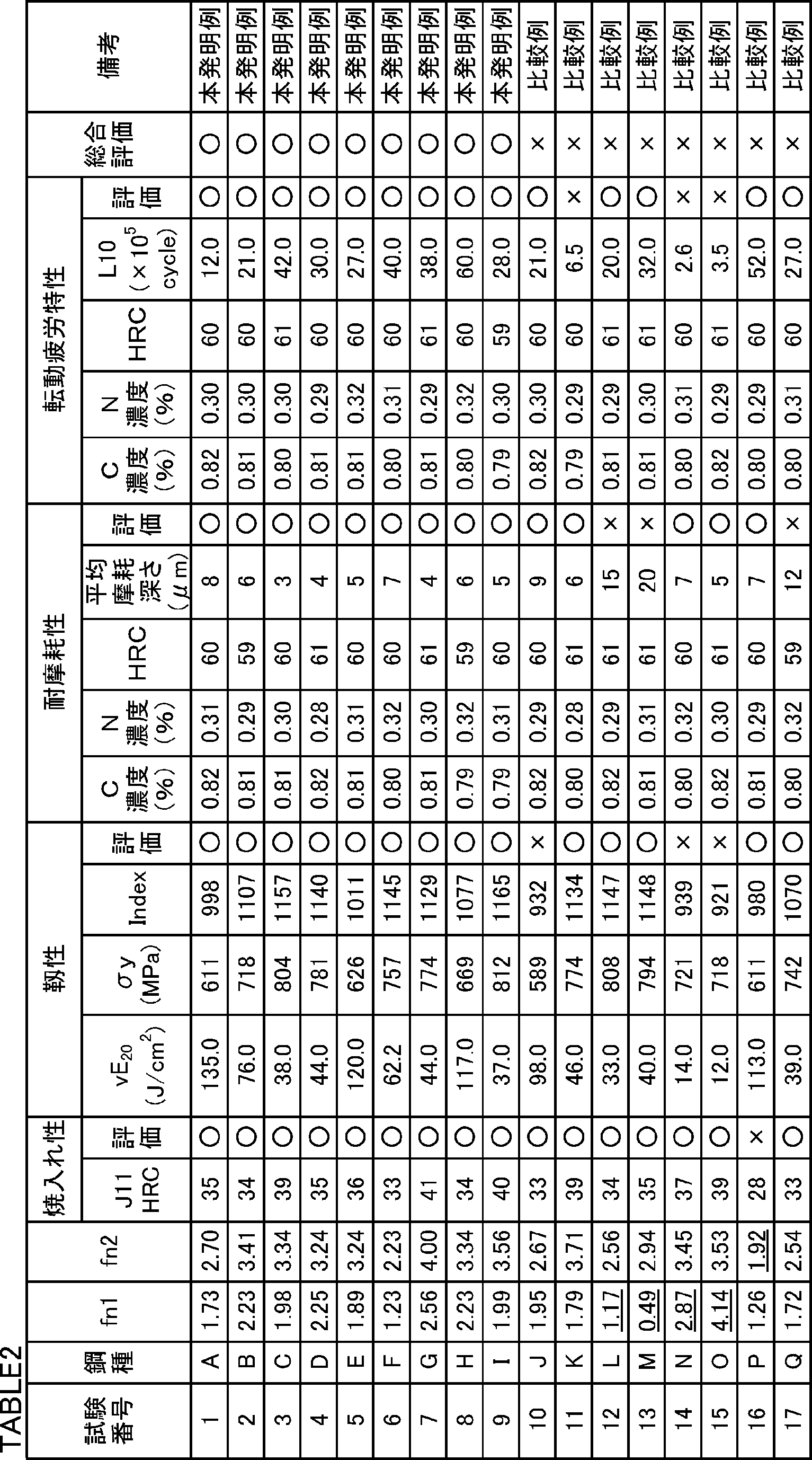
靭性評価試験を次の方法で実施した。各試験番号の直径30mmの棒鋼に対して、図1に示すヒートパターンの焼入れ及び焼戻しを実施した。図1を参照して、焼入れ処理では、焼入れ温度は900℃とし、保持時間を6時間とした。保持時間経過後の棒鋼を油冷した(図中「OQ」と記載)。焼戻し処理では、焼戻し温度を180℃とし、保持時間を2時間とした。保持時間経過後の棒鋼を空冷した(図中「AC」と記載)。 [Toughness evaluation test]
The toughness evaluation test was carried out by the following method. The heat pattern quenching and tempering shown in FIG. Referring to FIG. 1, in the quenching process, the quenching temperature was 900 ° C. and the holding time was 6 hours. The steel bar after the holding time elapsed was oil-cooled (described as “OQ” in the figure). In the tempering treatment, the tempering temperature was 180 ° C. and the holding time was 2 hours. The steel bar after the holding time elapsed was air-cooled (described as “AC” in the figure).
Index=σy×(vE20)0.1 Using the obtained Charpy impact value vE 20 (J / cm 2 ) and 0.2% yield strength σy (MPa), the toughness evaluation index Index was determined by the following equation.
Index = σy × (vE 20 ) 0.1
浸炭窒化軸受部品の耐摩耗性評価試験を次の方法で実施した。直径30mmの棒鋼から図2に示す小ローラ試験片の中間品を作製した。図2は、小ローラ試験片の中間品の一部断面を示す側面図及び横断面図である。図2中の数値は、中間品の各部位の寸法(mm)を示す。 [Abrasion resistance evaluation test]
The wear resistance evaluation test of carbonitrided bearing parts was carried out by the following method. An intermediate product of a small roller test piece shown in FIG. 2 was produced from a steel bar having a diameter of 30 mm. FIG. 2 is a side view and a cross-sectional view showing a partial cross section of an intermediate product of a small roller test piece. The numerical value in FIG. 2 shows the dimension (mm) of each site | part of an intermediate product.

試験後の小ローラ試験片の試験部の表面のうち、摺動部分以外の領域(以下、未摺動部分という)において、円周方向に対して90°ピッチで4箇所の測定位置を特定した。特定された4箇所の測定位置において、JIS Z2245(2011)に準拠して、Cスケールを用いたロックウェル硬さ試験を実施した。各測定箇所のロックウェルC硬さHRCの平均を、表面でのロックウェルC硬さHRCと定義した。 [Surface hardness]
Four measurement positions were specified at 90 ° pitches in the circumferential direction in the region other than the sliding portion (hereinafter referred to as the non-sliding portion) in the surface of the test portion of the small roller test piece after the test. . At the four specified measurement positions, a Rockwell hardness test using a C scale was performed in accordance with JIS Z2245 (2011). The average Rockwell C hardness HRC at each measurement location was defined as the Rockwell C hardness HRC at the surface.
小ローラ試験片の試験部の未摺動部分を軸方向に対して垂直に切断した。未摺動部を含む切断面を含む試験片を採取し、切断面に対して埋め込み研磨仕上げを行った。その後、電子線マイクロアナライザ(EPMA)を用いて、未摺動部分の表面から10μm深さまで、0.1μmピッチでC濃度及びN濃度を測定した。測定された値の平均値を、表面C濃度(質量%)及び表面N濃度(質量%)と定義した。 [Surface C concentration and surface N concentration]
The non-sliding part of the test part of the small roller test piece was cut perpendicular to the axial direction. A test piece including a cut surface including a non-sliding portion was collected, and the cut surface was embedded and polished. Then, C density | concentration and N density | concentration were measured with the 0.1 micrometer pitch from the surface of the non-sliding part to the 10 micrometer depth using the electron beam microanalyzer (EPMA). The average value of the measured values was defined as the surface C concentration (mass%) and the surface N concentration (mass%).
表面起点はく離寿命評価試験を次の方法で実施した。直径60mmの棒鋼から、直径60mm、厚さ5.5mmの円板状の粗試験片をスライスして採取した。粗試験片の厚さ(5.5mm)は、棒鋼の長手方向に相当した。 [Surface origin peeling life evaluation test]
The surface origin peeling life evaluation test was carried out by the following method. A disk-shaped rough test piece having a diameter of 60 mm and a thickness of 5.5 mm was sliced and collected from a steel bar having a diameter of 60 mm. The thickness of the rough specimen (5.5 mm) corresponded to the longitudinal direction of the steel bar.
表2に試験結果を示す。表2を参照して、試験番号1~9の軸受用鋼材の化学組成は適切であり、式(1)及び式(2)を満たした。そのため、これらの試験番号の鋼材の焼入れ性は高く、焼入れ及び焼戻し後の靭性も高かった。 [Test results]
Table 2 shows the test results. Referring to Table 2, the chemical compositions of the bearing steel materials of Test Nos. 1 to 9 are appropriate and satisfy the formulas (1) and (2). Therefore, the hardenability of the steel materials of these test numbers was high, and the toughness after quenching and tempering was also high.
表1中の鋼種A~Iの直径30mmの棒鋼から、実施例1と同様に、図2に示す小ローラ試験片の中間品を作製した。 [Abrasion resistance evaluation test]
In the same manner as in Example 1, an intermediate product of the small roller test piece shown in FIG. 2 was prepared from steel bars A to I having a diameter of 30 mm in Table 1.
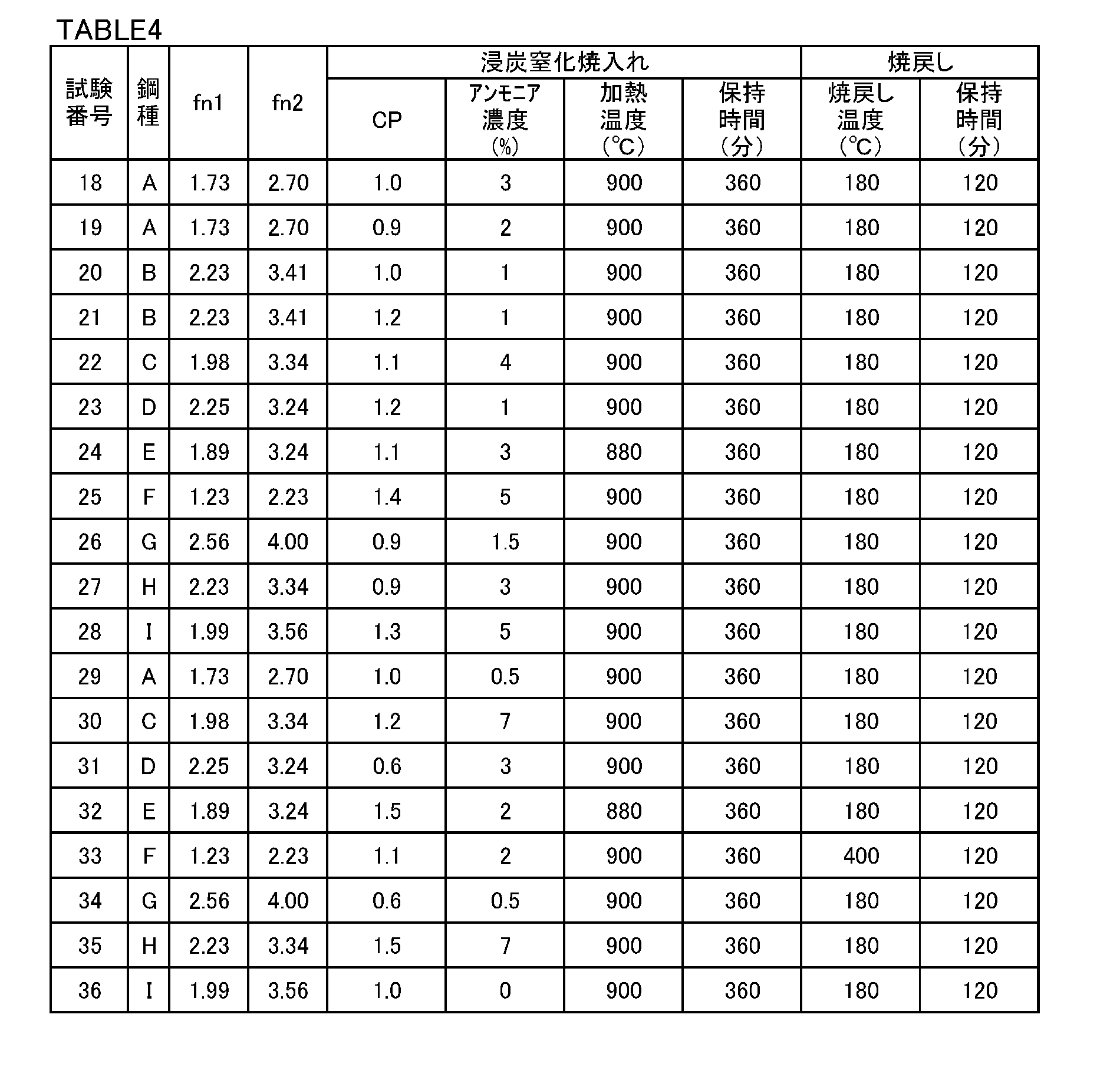
表1中の鋼種A~Iの直径60mmの棒鋼から、実施例1と同様に、直径60mm、厚さ5.5mmの円板状の粗試験片をスライスして採取した。 [Surface origin peeling life evaluation test]
In the same manner as in Example 1, a disk-shaped rough test piece having a diameter of 60 mm and a thickness of 5.5 mm was sliced and collected from steel bars A to I having a diameter of 60 mm in Table 1.
試験結果を表5に示す。 [Test results]
The test results are shown in Table 5.
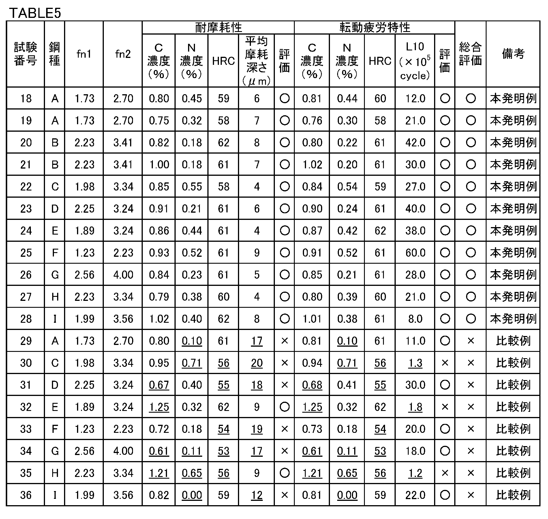
Claims (2)
- 質量%で、
C:0.15~0.45%、
Si:0.50%以下、
Mn:0.40~1.50%、
P:0.015%以下、
S:0.005%以下、
Cr:0.30~2.0%、
Mo:0.10~0.35%、
V:0.20~0.40%、
Al:0.005~0.10%、
N:0.030%以下、
O:0.0015%以下、
B:0~0.0050%、
Nb:0~0.10%、及び、
Ti:0~0.10%を含有し、残部がFe及び不純物からなり、式(1)及び式(2)を満たす化学組成を有し、
表面におけるC濃度が0.7~1.2%であり、N濃度が0.15~0.6%であり、
表面におけるロックウェル硬さHRCが58~65である、浸炭窒化軸受部品。
1.20<0.4Cr+0.4Mo+4.5V<2.60 ・・・(1)
2.7C+0.4Si+Mn+0.8Cr+Mo+V>2.20 ・・・(2)
ここで、式(1)及び式(2)中の各元素記号には、対応する元素の含有量(質量%)が代入される。 % By mass
C: 0.15-0.45%,
Si: 0.50% or less,
Mn: 0.40 to 1.50%,
P: 0.015% or less,
S: 0.005% or less,
Cr: 0.30 to 2.0%,
Mo: 0.10 to 0.35%,
V: 0.20 to 0.40%,
Al: 0.005 to 0.10%,
N: 0.030% or less,
O: 0.0015% or less,
B: 0 to 0.0050%,
Nb: 0 to 0.10%, and
Ti: 0 to 0.10% is contained, the balance is Fe and impurities, and has a chemical composition satisfying the formulas (1) and (2),
C concentration on the surface is 0.7 to 1.2%, N concentration is 0.15 to 0.6%,
Carbonitrided bearing parts having a Rockwell hardness HRC of 58 to 65 on the surface.
1.20 <0.4Cr + 0.4Mo + 4.5V <2.60 (1)
2.7C + 0.4Si + Mn + 0.8Cr + Mo + V> 2.20 (2)
Here, the content (mass%) of a corresponding element is substituted for each element symbol in the formulas (1) and (2). - 請求項1に記載の浸炭窒化軸受部品であって、
B:0.0003~0.0050%、
Nb:0.005~0.10%、及び、
Ti:0.005~0.10%を含有する、浸炭窒化軸受部品。
The carbonitrided bearing component according to claim 1,
B: 0.0003 to 0.0050%,
Nb: 0.005 to 0.10%, and
Carbonitrided bearing parts containing Ti: 0.005 to 0.10%.
Priority Applications (6)
| Application Number | Priority Date | Filing Date | Title |
|---|---|---|---|
| CN201580041247.0A CN106574338B (en) | 2014-07-29 | 2015-07-29 | Carbo-nitriding parts of bearings |
| EP15827899.4A EP3176278B1 (en) | 2014-07-29 | 2015-07-29 | Carbonitrided bearing member |
| JP2016537752A JP6205060B2 (en) | 2014-07-29 | 2015-07-29 | Carbonitriding bearing parts |
| KR1020177004848A KR20170033414A (en) | 2014-07-29 | 2015-07-29 | Carbonitrided bearing member |
| US15/328,109 US10358706B2 (en) | 2014-07-29 | 2015-07-29 | Carbonitrided bearing part |
| KR1020197006959A KR20190028568A (en) | 2014-07-29 | 2015-07-29 | Carbonitrided bearing member |
Applications Claiming Priority (2)
| Application Number | Priority Date | Filing Date | Title |
|---|---|---|---|
| JP2014-153944 | 2014-07-29 | ||
| JP2014153944 | 2014-07-29 |
Publications (1)
| Publication Number | Publication Date |
|---|---|
| WO2016017160A1 true WO2016017160A1 (en) | 2016-02-04 |
Family
ID=55217072
Family Applications (2)
| Application Number | Title | Priority Date | Filing Date |
|---|---|---|---|
| PCT/JP2015/003799 WO2016017162A1 (en) | 2014-07-29 | 2015-07-29 | Steel for carbonitrided bearing |
| PCT/JP2015/003797 WO2016017160A1 (en) | 2014-07-29 | 2015-07-29 | Carbonitrided bearing member |
Family Applications Before (1)
| Application Number | Title | Priority Date | Filing Date |
|---|---|---|---|
| PCT/JP2015/003799 WO2016017162A1 (en) | 2014-07-29 | 2015-07-29 | Steel for carbonitrided bearing |
Country Status (6)
| Country | Link |
|---|---|
| US (2) | US10358706B2 (en) |
| EP (2) | EP3176278B1 (en) |
| JP (2) | JP6205061B2 (en) |
| KR (4) | KR20190028568A (en) |
| CN (2) | CN106661691B (en) |
| WO (2) | WO2016017162A1 (en) |
Cited By (5)
| Publication number | Priority date | Publication date | Assignee | Title |
|---|---|---|---|---|
| CN106498304A (en) * | 2016-09-12 | 2017-03-15 | 北京工业大学 | A kind of corrosion resisting bearing and preparation method thereof |
| JP2018044197A (en) * | 2016-09-13 | 2018-03-22 | 株式会社ジェイテクト | Steel member and method for producing the same |
| US10047797B2 (en) | 2015-12-09 | 2018-08-14 | Jtekt Corporation | Bearing constituent member, method of manufacturing bearing constituent member, and rolling bearing |
| WO2020138458A1 (en) * | 2018-12-27 | 2020-07-02 | 日本製鉄株式会社 | Carbonitrided bearing component |
| WO2020138450A1 (en) * | 2018-12-27 | 2020-07-02 | 日本製鉄株式会社 | Steel material capable of being used as raw material for carbonitrided bearing component |
Families Citing this family (11)
| Publication number | Priority date | Publication date | Assignee | Title |
|---|---|---|---|---|
| JP6772499B2 (en) * | 2016-03-18 | 2020-10-21 | 日本製鉄株式会社 | Steel parts and their manufacturing methods |
| JP6974983B2 (en) * | 2017-08-25 | 2021-12-01 | 株式会社ジェイテクト | Rolling sliding member and its manufacturing method, and rolling bearing provided with the rolling sliding member. |
| US11168387B2 (en) | 2017-08-25 | 2021-11-09 | Nippon Steel Corporation | Steel material for carburized bearing part |
| CN108487958A (en) * | 2018-01-30 | 2018-09-04 | 重庆科马工贸有限公司 | A kind of valve rocker |
| CN110983178B (en) * | 2019-12-09 | 2021-09-07 | 江阴兴澄特种钢铁有限公司 | Steel for ball screw bearing and manufacturing method thereof |
| JPWO2021201157A1 (en) * | 2020-03-31 | 2021-10-07 | ||
| JP2021195983A (en) * | 2020-06-12 | 2021-12-27 | Ntn株式会社 | Tapered roller bearing |
| JP2022165628A (en) * | 2021-04-20 | 2022-11-01 | 大同特殊鋼株式会社 | Carbonitriding steel material and carbonitrided steel material |
| CN113528752A (en) * | 2021-06-28 | 2021-10-22 | 南京钢铁股份有限公司 | Smelting process of steel for carburizing bearing |
| CN113549833A (en) * | 2021-07-21 | 2021-10-26 | 承德建龙特殊钢有限公司 | Steel for wind power variable pitch bearing and preparation method thereof |
| CN115717212A (en) * | 2021-08-25 | 2023-02-28 | 宝山钢铁股份有限公司 | Gear shaft steel and manufacturing method thereof |
Citations (6)
| Publication number | Priority date | Publication date | Assignee | Title |
|---|---|---|---|---|
| JP2005042188A (en) * | 2003-07-25 | 2005-02-17 | Daido Steel Co Ltd | Carbonitrided bearing steel with excellent rolling fatigue life under debris-contaminated environment |
| JP2008280583A (en) * | 2007-05-10 | 2008-11-20 | Daido Steel Co Ltd | Case-hardening steel excellent in surface fatigue strength due to hydrogen embrittlement |
| WO2010082685A1 (en) * | 2009-01-16 | 2010-07-22 | 新日本製鐵株式会社 | Steel for surface hardening for machine structural use, and component for machine structural use |
| JP2011080099A (en) * | 2009-10-02 | 2011-04-21 | Kobe Steel Ltd | Case hardened steel component, and method for manufacturing the same |
| JP2011080100A (en) * | 2009-10-02 | 2011-04-21 | Kobe Steel Ltd | Steel for machine structural use, and method for producing the same |
| JP2012112024A (en) * | 2010-11-26 | 2012-06-14 | Kobe Steel Ltd | Case hardening steel with little heat-treatment strain |
Family Cites Families (11)
| Publication number | Priority date | Publication date | Assignee | Title |
|---|---|---|---|---|
| JPH06287712A (en) | 1993-03-31 | 1994-10-11 | Sumitomo Metal Ind Ltd | Steel parts excellent in rolling fatigue life |
| JP3413975B2 (en) | 1994-08-08 | 2003-06-09 | 日本精工株式会社 | Rolling bearing with excellent wear resistance |
| JP3538995B2 (en) * | 1994-09-29 | 2004-06-14 | 日本精工株式会社 | Rolling bearing |
| JPH0979338A (en) * | 1995-09-13 | 1997-03-25 | Kobe Steel Ltd | Material of rolling body for toroidal type continuously variable transmission having excellent rolling factigue strength and rolling body |
| JP3909902B2 (en) * | 1996-12-17 | 2007-04-25 | 株式会社小松製作所 | Steel parts for high surface pressure resistance and method for producing the same |
| JPH1112684A (en) | 1997-06-19 | 1999-01-19 | Kobe Steel Ltd | Case hardening steel for cold forging |
| CN101248202A (en) * | 2005-08-22 | 2008-08-20 | 新日本制铁株式会社 | Highly strong, thick electric resistance-welded steel pipe excellent in quenching property, hot forming processability and fatigue strength, and method for manufacture thereof |
| DE102007057421A1 (en) * | 2007-08-27 | 2009-03-05 | Georgsmarienhütte Gmbh | Steel for the production of massively formed machine components |
| WO2009054530A1 (en) * | 2007-10-24 | 2009-04-30 | Nippon Steel Corporation | Carbonitrided induction-hardened steel part with excellent rolling contact fatigue strength at high temperature and process for producing the same |
| JP5489111B2 (en) * | 2009-03-25 | 2014-05-14 | Ntn株式会社 | Bearing parts, rolling bearings and bearing parts manufacturing method |
| KR101369113B1 (en) * | 2009-10-02 | 2014-03-04 | 가부시키가이샤 고베 세이코쇼 | Steel for machine structural use, manufacturing method for same, case hardened steel components, and manufacturing method for same |
-
2015
- 2015-07-29 KR KR1020197006959A patent/KR20190028568A/en active Application Filing
- 2015-07-29 CN CN201580040957.1A patent/CN106661691B/en active Active
- 2015-07-29 JP JP2016537754A patent/JP6205061B2/en active Active
- 2015-07-29 WO PCT/JP2015/003799 patent/WO2016017162A1/en active Application Filing
- 2015-07-29 WO PCT/JP2015/003797 patent/WO2016017160A1/en active Application Filing
- 2015-07-29 KR KR1020177004849A patent/KR20170032449A/en active Search and Examination
- 2015-07-29 EP EP15827899.4A patent/EP3176278B1/en active Active
- 2015-07-29 US US15/328,109 patent/US10358706B2/en active Active
- 2015-07-29 EP EP15826735.1A patent/EP3176276B1/en active Active
- 2015-07-29 KR KR1020177004848A patent/KR20170033414A/en active Search and Examination
- 2015-07-29 KR KR1020197006960A patent/KR20190027967A/en active Application Filing
- 2015-07-29 CN CN201580041247.0A patent/CN106574338B/en active Active
- 2015-07-29 JP JP2016537752A patent/JP6205060B2/en active Active
- 2015-07-29 US US15/328,131 patent/US10538832B2/en active Active
Patent Citations (6)
| Publication number | Priority date | Publication date | Assignee | Title |
|---|---|---|---|---|
| JP2005042188A (en) * | 2003-07-25 | 2005-02-17 | Daido Steel Co Ltd | Carbonitrided bearing steel with excellent rolling fatigue life under debris-contaminated environment |
| JP2008280583A (en) * | 2007-05-10 | 2008-11-20 | Daido Steel Co Ltd | Case-hardening steel excellent in surface fatigue strength due to hydrogen embrittlement |
| WO2010082685A1 (en) * | 2009-01-16 | 2010-07-22 | 新日本製鐵株式会社 | Steel for surface hardening for machine structural use, and component for machine structural use |
| JP2011080099A (en) * | 2009-10-02 | 2011-04-21 | Kobe Steel Ltd | Case hardened steel component, and method for manufacturing the same |
| JP2011080100A (en) * | 2009-10-02 | 2011-04-21 | Kobe Steel Ltd | Steel for machine structural use, and method for producing the same |
| JP2012112024A (en) * | 2010-11-26 | 2012-06-14 | Kobe Steel Ltd | Case hardening steel with little heat-treatment strain |
Cited By (9)
| Publication number | Priority date | Publication date | Assignee | Title |
|---|---|---|---|---|
| US10047797B2 (en) | 2015-12-09 | 2018-08-14 | Jtekt Corporation | Bearing constituent member, method of manufacturing bearing constituent member, and rolling bearing |
| CN106498304A (en) * | 2016-09-12 | 2017-03-15 | 北京工业大学 | A kind of corrosion resisting bearing and preparation method thereof |
| JP2018044197A (en) * | 2016-09-13 | 2018-03-22 | 株式会社ジェイテクト | Steel member and method for producing the same |
| WO2020138458A1 (en) * | 2018-12-27 | 2020-07-02 | 日本製鉄株式会社 | Carbonitrided bearing component |
| WO2020138450A1 (en) * | 2018-12-27 | 2020-07-02 | 日本製鉄株式会社 | Steel material capable of being used as raw material for carbonitrided bearing component |
| JPWO2020138450A1 (en) * | 2018-12-27 | 2021-10-21 | 日本製鉄株式会社 | Steel material used as a material for carburized nitriding bearing parts |
| JPWO2020138458A1 (en) * | 2018-12-27 | 2021-10-28 | 日本製鉄株式会社 | Carburized nitride bearing parts |
| JP7095117B2 (en) | 2018-12-27 | 2022-07-04 | 日本製鉄株式会社 | Carburized nitriding bearing parts |
| JP7095116B2 (en) | 2018-12-27 | 2022-07-04 | 日本製鉄株式会社 | Steel material used as a material for carburized nitriding bearing parts |
Also Published As
| Publication number | Publication date |
|---|---|
| CN106574338B (en) | 2018-07-10 |
| US10358706B2 (en) | 2019-07-23 |
| WO2016017162A1 (en) | 2016-02-04 |
| EP3176276B1 (en) | 2019-12-18 |
| KR20170033414A (en) | 2017-03-24 |
| JP6205061B2 (en) | 2017-09-27 |
| US20170218489A1 (en) | 2017-08-03 |
| EP3176278A1 (en) | 2017-06-07 |
| CN106661691B (en) | 2018-07-24 |
| JPWO2016017160A1 (en) | 2017-05-25 |
| JPWO2016017162A1 (en) | 2017-04-27 |
| KR20170032449A (en) | 2017-03-22 |
| EP3176276A1 (en) | 2017-06-07 |
| US10538832B2 (en) | 2020-01-21 |
| US20170211170A1 (en) | 2017-07-27 |
| KR20190028568A (en) | 2019-03-18 |
| KR20190027967A (en) | 2019-03-15 |
| CN106661691A (en) | 2017-05-10 |
| EP3176278B1 (en) | 2019-03-20 |
| EP3176278A4 (en) | 2017-12-27 |
| JP6205060B2 (en) | 2017-09-27 |
| CN106574338A (en) | 2017-04-19 |
| EP3176276A4 (en) | 2018-04-04 |
Similar Documents
| Publication | Publication Date | Title |
|---|---|---|
| JP6205060B2 (en) | Carbonitriding bearing parts | |
| EP3088550B1 (en) | Production method of carburized steel component and carburized steel component | |
| JP6610808B2 (en) | Soft nitriding steel and parts | |
| CN113260728B (en) | Carbonitrided bearing component | |
| JP2011208250A (en) | Steel for nitriding and induction hardening and nitrided, induction-hardened component | |
| WO2011065593A1 (en) | Ingot for bearing, and process for producing bearing steel | |
| JP7095116B2 (en) | Steel material used as a material for carburized nitriding bearing parts | |
| CN115667566B (en) | Carburized bearing component | |
| JP7464822B2 (en) | Steel for bearing raceways and bearing raceways | |
| JP2022170056A (en) | steel | |
| JP7469596B2 (en) | Bearing Steel | |
| JP7460884B2 (en) | bearing steel | |
| JP7360060B2 (en) | steel and bearings | |
| TW201843317A (en) | Cement steel component and steel material having excellent stability of rolling fatigue life, and method for manufacturing same | |
| JP2022042439A (en) | Steel | |
| JP2024034953A (en) | Steel materials and steel parts | |
| JP2006161143A (en) | Carburizing steel having excellent rolling fatigue life and high temperature carburizing property | |
| JP2018053338A (en) | Carburized component excellent in wear resistance, and process for producing the same |
Legal Events
| Date | Code | Title | Description |
|---|---|---|---|
| 121 | Ep: the epo has been informed by wipo that ep was designated in this application |
Ref document number: 15827899 Country of ref document: EP Kind code of ref document: A1 |
|
| ENP | Entry into the national phase |
Ref document number: 2016537752 Country of ref document: JP Kind code of ref document: A |
|
| REEP | Request for entry into the european phase |
Ref document number: 2015827899 Country of ref document: EP |
|
| WWE | Wipo information: entry into national phase |
Ref document number: 15328109 Country of ref document: US |
|
| NENP | Non-entry into the national phase |
Ref country code: DE |
|
| ENP | Entry into the national phase |
Ref document number: 20177004848 Country of ref document: KR Kind code of ref document: A |