WO2016016993A1 - 電動機の駆動制御を行う駆動装置の試験を行うための試験装置 - Google Patents
電動機の駆動制御を行う駆動装置の試験を行うための試験装置 Download PDFInfo
- Publication number
- WO2016016993A1 WO2016016993A1 PCT/JP2014/070186 JP2014070186W WO2016016993A1 WO 2016016993 A1 WO2016016993 A1 WO 2016016993A1 JP 2014070186 W JP2014070186 W JP 2014070186W WO 2016016993 A1 WO2016016993 A1 WO 2016016993A1
- Authority
- WO
- WIPO (PCT)
- Prior art keywords
- item
- definition file
- value
- identifier
- drive device
- Prior art date
- Legal status (The legal status is an assumption and is not a legal conclusion. Google has not performed a legal analysis and makes no representation as to the accuracy of the status listed.)
- Ceased
Links
Images


Classifications
-
- G—PHYSICS
- G01—MEASURING; TESTING
- G01R—MEASURING ELECTRIC VARIABLES; MEASURING MAGNETIC VARIABLES
- G01R31/00—Arrangements for testing electric properties; Arrangements for locating electric faults; Arrangements for electrical testing characterised by what is being tested not provided for elsewhere
-
- H—ELECTRICITY
- H02—GENERATION; CONVERSION OR DISTRIBUTION OF ELECTRIC POWER
- H02P—CONTROL OR REGULATION OF ELECTRIC MOTORS, ELECTRIC GENERATORS OR DYNAMO-ELECTRIC CONVERTERS; CONTROLLING TRANSFORMERS, REACTORS OR CHOKE COILS
- H02P29/00—Arrangements for regulating or controlling electric motors, appropriate for both AC and DC motors
Definitions
- the present invention relates to a test technique for a drive device that performs drive control of an electric motor.
- the torque command is a command for specifying the output torque of the electric motor
- the rotation speed command is a command for specifying the rotation speed of the electric motor.
- the drive device is an inverter that converts DC power supplied from the vehicle-mounted battery into AC power and supplies the AC power to the motor.
- the drive device adjusts the amplitude and frequency of AC power applied to the electric motor in accordance with various commands given from the control device. Thereby, the torque or rotational speed of the electric motor changes, and travel control according to the driving operation is realized.
- This type of drive device has values corresponding to the specifications of the motors subject to drive control and the specifications of various sensors for detecting the drive state of the motor (output torque, rotation speed, etc.) for each item such as motor constants.
- the driving device controls the driving of the electric motor while referring to the value. While the specifications of the motors and sensors mounted on the EV may differ depending on the EV model, if the values of the above items are not set appropriately according to these specifications, the drive control of the motor It may cause trouble. For this reason, the EV manufacturer performs a test for appropriately setting the values of the above items according to the specifications of the electric motor and the sensor mounted on the EV.
- test device such as a personal computer is connected to the drive device instead of the control device, and various commands are given from the test device to the drive device. Then, while measuring the basic characteristics such as the current flowing through the motor, the voltage applied to the motor, or the output torque of the motor, the value of each item is adjusted to find the optimum value.
- Patent Document 1 is an example of a prior art document relating to this type of test.
- an item definition file that defines items for which values are to be set in the drive device to be tested is stored in advance in the test device, and checks are made for any missing values in the test process.
- setting item management such as performing according to the stored contents of the file is performed.
- the present invention has been made in view of the problems described above, and provides a technique for preventing the occurrence of problems caused by inconsistencies between an item definition file used in a driving device test process and a driving device. With the goal.
- the item definition file used in the test process of the drive device is acquired from the drive device to be tested. For this reason, inconsistency between the two does not occur, and problems caused by the inconsistency between the two (that is, a missing value setting or an incorrect value setting) are prevented.
- initial setting values at the time of factory shipment of the drive device for the item indicated by the identifier are written in association with the identifier indicating the item.
- the control unit of the test apparatus acquires the value of each item set in the driving device by communication via the communication interface unit, and displays it in association with the identifier of the item together with the initial setting value for the item. Display on the device.
- the control unit of the test apparatus executes a process for notifying an item whose value acquired by the communication interface unit is different from an initial set value. For example, when displaying the setting values (values set in the driving device) of each item and the initial setting values on the display device in a tabular format, the control unit is set to a value different from the initial setting value. For example, a predetermined mark such as “*” is assigned to the item and displayed on the display device. According to such an aspect, confirmation of the changed part from the time of factory shipment becomes easier, and the efficiency and maintainability of the test of the drive device are further improved.
- control unit of the test apparatus sets the value of each item set in the drive device as an initial setting value at the time of shipment from the factory when an initialization instruction is given. It is characterized by correcting. According to such an aspect, the setting value changed with the execution of the test can be easily returned to the initial setting value at the time of shipment from the factory, and the convenience in the test of the drive device is improved.
- the item definition file includes a restart indicating whether or not the drive device needs to be restarted when the value of the item indicated by the identifier is changed in association with the identifier of each item. Necessity flag is written. Then, the control unit of the test apparatus notifies each item of whether or not it is necessary to restart according to the contents of the item definition file (for example, “#” or the like in the identifier of an item that needs to be restarted due to a value update) The predetermined mark is given and displayed on the display device, etc.). According to such an aspect, when the value is changed, the tester can surely grasp the items that need to be restarted, and forget to restart even though the value of the item has been changed. It is possible to prevent operation / operation confirmation errors.
- FIG. 1 is a diagram illustrating a configuration example of a test system 1 including a test apparatus 10 according to an embodiment of the present invention.
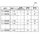
- 3 is a diagram showing an example of an item definition file 210 stored in the storage unit of the drive device 20 to be tested by the test apparatus 10.
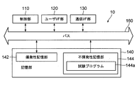
- FIG. 2 is a diagram illustrating a configuration example of the test apparatus 10.
- FIG. It is a figure which shows an example of the process which the control part 110 of the test apparatus 10 performs according to the test program 144a.
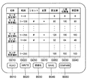
- 4 is a diagram illustrating an example of a setting value adjustment support screen that is displayed on the display unit of the user interface unit 120 by the control unit 110 of the test apparatus 10 according to a test program 144a.
- FIG. 1 is a diagram illustrating a configuration example of a test system 1 including a test apparatus 10 according to an embodiment of the present invention.
- This test system 1 is for testing the drive device 20 mounted on the EV together with the electric motor 30.
- a test performed at the manufacturer at the time of shipment of EV or a test at the time of maintenance inspection can be given.
- a test system 1 includes a drive device 20 to be tested, an electric motor 30 that is driven and controlled by the drive device 20, and a test device 10 that serves as a control device for the drive device 20 in a test process. Including.
- the motor 30 is a three-phase AC motor.
- the drive device 20 is an inverter that converts DC power supplied from a DC power supply (not shown in FIG. 1) into three-phase AC power PW and supplies the same to the motor 30.
- the drive device 20 includes a power conversion unit that converts DC power into AC power, a control unit that performs operation control of the power conversion unit, and a storage unit (none of which is shown in FIG. 1).
- the storage unit controls the amplitude of each phase of the three-phase AC voltage applied to the electric motor 30 in accordance with various commands given from the control device (VCU in actual operation, test device 10 in the present embodiment).
- a control program for causing the control unit to execute is stored.
- the storage unit stores in advance for each item (for example, a motor constant) determined in accordance with one of various sensors (not shown in FIG. 1) for detecting the specification of the motor 30 and the driving state of the motor 30.
- the set value is stored.
- the values of these items are appropriately referred to by the control unit during the execution of the control program.
- the item definition file 210 is stored in advance in the storage unit of the driving device 20.
- FIG. 2 is a diagram illustrating an example of the contents of the item definition file 210.
- range data, a restart necessity flag, initial value data, and previous value data are written in association with identifiers uniquely indicating each item whose value is stored in the storage unit of the driving device 20. Yes.
- An example of the identifier is a character string that represents the name of the item.
- the range data is data indicating a range of possible values of the item indicated by the identifier associated with the range data.
- the restart necessity flag is a flag indicating whether or not the drive device 20 needs to be restarted when the value of the item indicated by the identifier associated with the restart necessity flag is updated (if restart is necessary, “ 1 ”is a flag that is set to“ 0 ”if there is no need for restart).
- the initial value data is data representing an initial setting value at the time of factory shipment of the drive device 20 for the item indicated by the identifier associated with the initial value data.
- the previous value data is data indicating a value set in the previous test with respect to the item indicated by the identifier associated with the previous value data. When the test of the drive device 20 is performed for the first time by the test apparatus 10, the same data as the initial value data is set in the previous value data.
- the item definition file 210 is paired with the drive device 20, is created by the manufacturer of the drive device 20, and is provided to the EV manufacturer or the like in a state of being installed in the storage unit of the drive device 20.
- the item definition file 210 shown in FIG. 2 includes motor setting value 1 to motor setting value N (N is an arbitrary natural number) and sensor setting value 1 to sensor setting value M. This indicates that there are N + M types of items (M is an arbitrary natural number).
- the motor setting value 1 to the motor setting value N are items according to the specifications of the electric motor 30, and the sensor setting value 1 to the sensor setting value M are items according to the specifications of the sensor for detecting the driving state of the electric motor 30. .
- the range of values that can be taken is 1 to 8, and it is not necessary to restart the drive device 20 even if the value of the item is changed. This indicates that the factory default is 8 and the previous value is 8.
- the possible range is 1 to 128. When changed, it indicates that the driving device 20 needs to be restarted, the initial setting value at the time of factory shipment is 100, and the previous value is 90.
- the test apparatus 10 is a personal computer, for example, and is connected to the drive apparatus 20 via a signal line such as a twisted pair cable.
- various instructions are given from the test apparatus 10 to the drive apparatus 20 through the signal line to observe changes in the drive state of the electric motor 30, and each item stored in the storage unit of the drive apparatus 20 is monitored.
- setting values By reading out values (hereinafter referred to as setting values) to the test apparatus 10 and confirming them, a test for finding the optimum values of these items is advanced.
- the test device 10 prior to the start of the test of the drive device 20, the test device 10 is made to acquire the item definition file 210 stored in the drive device 20, and the test is advanced according to the stored contents of the item definition file 210.
- the test apparatus 10 that remarkably shows the features of the present embodiment will be mainly described.
- FIG. 3 is a diagram illustrating a configuration example of the test apparatus 10.
- the test apparatus 10 includes a control unit 110, a user interface (hereinafter abbreviated as “I / F”) unit 120, a communication I / F unit 130, a storage unit 140, and data between these components. It has a bus 160 that mediates transfer.
- I / F user interface
- the control unit 110 is, for example, a CPU (Central Processing Unit).
- the control unit 110 functions as a control center of the test apparatus 10 by executing the test program 144a stored in the storage unit 140 (more precisely, the nonvolatile storage unit 144). Details of processing executed by the control unit 110 in accordance with the test program 144a will be clarified later.
- the user I / F unit 120 includes a display unit and an operation unit (both not shown in FIG. 3).
- the display unit is composed of a display device such as a liquid crystal display and its drive circuit. Various screens for testing the drive device 20 are displayed on the display unit under the control of the control unit 110.
- the operation unit includes a pointing device such as a mouse and a keyboard. The operation unit is for causing the tester to perform various input operations for performing the test of the drive device 20, and the control unit 110 stores data corresponding to the content of the operation performed on the pointing device or the like. To give. As a result, the operation content of the person in charge of the test is transmitted to the control unit 110.
- the communication I / F unit 130 is, for example, a NIC (Network Interface Card), and is connected to the driving device 20 via a signal line.
- the communication I / F unit 130 provides the data received from the drive device 20 via the signal line to the control unit 110, and transmits the data provided from the control unit 110 to the drive device 20 via the signal line. .
- the storage unit 140 includes a volatile storage unit 142 and a nonvolatile storage unit 144 as shown in FIG.
- the volatile storage unit 142 is configured by a volatile memory such as a RAM (Random Access Memory).
- the volatile storage unit 142 is used by the control unit 110 as a work area when executing the test program 144a.
- the non-volatile storage unit 144 is configured by a non-volatile memory such as a hard disk or a flash memory.
- the nonvolatile storage unit 144 stores a test program 144a in advance.
- OS software that implements an OS (Operating System) is also stored in the nonvolatile storage unit 144, but is not shown because it is not relevant to the present invention.
- the control unit 110 reads the OS software from the non-volatile storage unit 144 to the volatile storage unit 142 when power to the test apparatus 10 (not shown) is turned on, and starts its execution. In this state, when an execution instruction for the test program 144a is given via the operation unit of the user I / F unit 120, the control unit 110 reads the test program 144a from the nonvolatile storage unit 144 to the volatile storage unit 142, Start its execution.
- FIG. 4 is a diagram illustrating a flow of operations performed by the control unit 110 in accordance with the test program 144a.
- the control unit 110 that has started the execution of the test program 144a first communicates with the drive device 20 via the communication I / F unit 130 to acquire the item definition file 210 (step SA100). More specifically, the control unit 110 transmits a transmission request REQ010 requesting transmission of the item definition file 210 to the driving device 20 via the communication I / F unit 130, and transmits a reply RES010 from the driving device 20 to the communication I.
- the item definition file 210 received via the / F unit 130 and written in the reply RES010 is written in the volatile storage unit 142, thereby completing the acquisition of the file.
- step SA110 the control unit 110 displays a setting value adjustment support screen (see FIG. 5) on the display unit of the user I / F unit 120 according to the contents of the item definition file 142 written in the volatile storage unit 142 (step SA110).
- step SA110 the control unit 110 sets each identifier stored in the item definition file 210 in the name field G010 of the setting value adjustment support screen, sets the value range represented by the same range data in the range field G020, The value represented by the initial value data is set in the factory initial value column G030, and the value represented by the previous value data is set in the previous value column G040.
- the reset column G050 of the set value adjustment support screen is a display item for notifying the testing staff of whether or not the drive device 20 needs to be restarted when the set value is updated.
- the control unit 110 uses a predetermined mark (in this embodiment, for informing the test person that the restart is necessary in the reset column G050 for items whose restart flag value is “1”. #) Is set. Note that the set value input / output column G060 and the change column G070 on the set value adjustment support screen are blank at the time of execution of the above step SA110, and a value and the like are displayed when a READ button B010 described later is pressed.
- the set value adjustment support screen is provided with five types of virtual operators: a READ button B010, a WRITE button B020, an initialization button B030, a SAVE button B040, and a COMPARE button B050.
- the roles of these virtual operators are as follows.
- the READ button B010 is a virtual operator that allows the tester to input read instructions for various setting values stored in the drive device to be tested.
- FIG. 4 shows an operation flow when the READ button B010 is pressed.
- the control unit 110 detects the pressing of the READ button B010 with reference to the operation content data given from the user I / F unit 120 (for other virtual operators). The same).
- the control unit 110 that has detected the pressing of the READ button B010 communicates with the connection-destination drive device 20 via the communication I / F unit 130, and acquires various setting values stored in the drive device 20 (step SA120). ).
- control unit 110 transmits a transmission request REQ020 requesting transmission of a set value to the driving device 20 via the communication I / F unit 130, and a reply RES020 from the driving device 20 is transmitted to the communication I / F.
- a transmission request REQ020 requesting transmission of a set value to the driving device 20 via the communication I / F unit 130
- reply RES020 from the driving device 20 is transmitted to the communication I / F.
- Each setting value received via the unit 130 and written in the reply RES020 is read. Thereby, acquisition of each set value is completed.
- step SA130 the control unit 110 updates the display contents of the set value input / output field G060 and the change field G070 in accordance with each set value acquired in step SA120. Specifically, for the set value input / output field G060, the control unit 110 sets the set value acquired in step SA120 for each item.
- the set value input / output column G060 can be rewritten by operating the operation unit of the user I / F unit 120, and the person in charge of the test can freely rewrite the value of the input / output column G060.
- the WRITE button B020 is a virtual operation element for causing the test person to input a setting value writing instruction for storing the setting value displayed in the setting value input / output field G060 in the driving apparatus to be tested.
- the control unit 110 Upon detecting the pressing of the WRITE button B020, the control unit 110 transmits each value displayed in the set value input / output field G060 and an identifier corresponding to the value via the communication I / F unit 130 to the connected drive device 20. And store the value as the set value of the item indicated by the identifier. As a result, each set value input via the set value adjustment support screen is reflected in the drive device to be tested.
- the initialization button B030 is a virtual operation element for causing the test person to input an initialization instruction for instructing to write back the values of the respective items stored in the driving apparatus to be tested to the factory default values. It is.
- the control unit 110 that has detected the pressing of the initialization button B030 transmits each initial value data and identifier stored in the item definition file 210 to the connected drive device 20 via the communication I / F unit 130. ,
- the setting value changed with the execution of the test of the driving device 20 can be easily returned to the initial setting value at the time of shipment from the factory. Will improve.
- the SAVE button B040 is a virtual operator that allows the tester to input a save instruction that instructs to save the item definition file 210 stored in the volatile storage unit 142 in the nonvolatile storage unit 144.
- the control unit 110 that has detected the pressing of the SAVE button B040 writes the item definition file 210 stored in the volatile storage unit 142 into the nonvolatile storage unit 144.
- the drive device 20 can be tested using the stored item definition file 210, and the drive device is started prior to the start of the test. It is not necessary to acquire the item definition file 210 from 20 one by one.
- an identifier indicating the driving device an identifier indicating the model of the driving device such as a character string indicating a model number or a character string indicating a manufacturing number
- the identifier is obtained from the drive device prior to the start of the test, and is associated with the item definition file and is nonvolatile. This is because it is possible to avoid inconsistency between the drive device to be tested and the item definition file used for the test by verifying whether the identifier matches the identifier stored in the storage unit 144.
- the COMPARE button B050 is a virtual operator that allows the tester to input a comparison instruction between the item definition file stored in the nonvolatile storage unit 144 and the item definition file stored in the drive device to be tested. .
- the control unit 110 that detects the pressing of the COMPARE button B050 compares the item definition file stored in the volatile storage unit 142 with the item definition file acquired from the test target drive device via the communication I / F unit 130. Then, the difference between them (increase / decrease in items or difference in values such as initial values) is notified.
- test apparatus 10 of the above embodiment has the user I / F unit 120 including the display unit and the operation unit, the user I / F unit 120 is omitted and is connected to the test apparatus 10 respectively.
- the user I / F unit 120 may serve as a display device, a keyboard, and the like.
- items for which values are set in the drive device 20 correspond to the specifications of the motor 30 (motor setting value 1 to motor setting value N) and sensors for detecting the driving state of the motor 30.
- items whose values are set in the drive device 20 may include items depending on both the specifications of the electric motor 30 and the specifications of the sensor.
- range data In the item definition file 210 of the above-described embodiment, range data, a restart necessity flag, initial value data, and an identifier indicating each item whose value is to be set in the drive device 20 to be tested, The previous value data was written.
- the range data may be omitted if it is not necessary to notify the person in charge of the test of the range of values for each item.
- the restart necessity flag may be omitted, and the initial setting value notification (or the presence or absence of a change from the initial setting value) ) Is not necessary, the initial value data may be omitted.
- the previous value notification is not required, the previous value data may be omitted. When it is required only to let the person in charge of the test know the items for which values need to be set without omission, only the identifier of each item needs to be written in the item definition file 210.
- inconsistency between the drive device 20 to be tested and the item definition file 210 can be surely avoided, and inconsistency between the test program 144a and the item definition file 210 (or the test program 144a and test Inconsistency of the target drive device) can be avoided reliably.
- test program 144 a is stored in advance in the nonvolatile storage unit 144 of the test apparatus 10.
- the test program 144a may be written on a computer-readable recording medium such as a CD-ROM (Compact Disk-Read Memory) or distributed by downloading via a telecommunication line such as the Internet. . This is because by operating a general computer according to the program distributed in this way, the computer can function as the test apparatus 10 of the present embodiment.
Landscapes
- Engineering & Computer Science (AREA)
- Power Engineering (AREA)
- Physics & Mathematics (AREA)
- General Physics & Mathematics (AREA)
- Testing Electric Properties And Detecting Electric Faults (AREA)
Abstract
駆動装置の試験行程において使用する項目適宜ファイルと駆動装置との不整合に起因する不具合(値の設定漏れや誤った値の設定)の発生を防止する。このため、駆動装置の試験装置に、以下の通信インタフェース部と記憶部と制御部とを設ける。通信インタフェース部には試験対象の駆動装置が接続される。駆動装置には駆動制御の対象となる電動機の仕様等に応じて定まる項目毎に予め値が設定されており、駆動装置の記憶部には上記各項目を一意に示す識別子の書き込まれた項目定義ファイルが予め記憶されている。制御部は、上記項目定義ファイルを通信インタフェース部を介した通信により上記駆動装置から取得し、当該駆動装置に値を設定するべき項目を示す識別子として当該項目定義ファイルに書き込まれている各識別子を表示装置に表示させる。
Description
この発明は、電動機の駆動制御を行う駆動装置の試験技術に関する。
近年、環境問題への関心の高まりに伴い、車載電池に充電された電力により走行する電気自動車(Electric Vehicle、以下、「EV」)が注目を集めている。EVには、車載電池の他に、三相交流電動機などの電動機と、電動機の駆動制御を行う駆動装置と、駆動装置の制御を行う制御装置とが搭載されている。制御装置は例えばVCU(Vehicle Control Unit)である。制御装置は信号線を介して駆動装置に接続されている。制御装置は運転者の運転操作に応じてトルク指令や回転数指令などの各種指令を生成し駆動装置に与える。トルク指令とは電動機の出力トルクを指定する指令であり、回転数指令とは電動機の回転数を指定する指令である。駆動装置は、車載電池から供給される直流電力を交流電力に変換して電動機に供給するインバータである。駆動装置は電動機に与える交流電力の振幅や周波数を制御装置から与えられる各種指令に応じて調整する。これにより、当該電動機のトルク或いは回転速度が変化し、運転操作に応じた走行制御が実現される。
この種の駆動装置には、モータ定数などの項目毎に駆動制御の対象の電動機の仕様や電動機の駆動状態(出力トルクや回転数等)を検出するための各種センサの仕様に応じた値が設定され、駆動装置は当該値を参照しつつ電動機の駆動制御を行う。EVに搭載される電動機の仕様やセンサの仕様はEVの車種に応じて異なる可能性がある一方、上記各項目の値がこれらの仕様に応じて適切に設定されていないと電動機の駆動制御に支障が生じる可能性がある。このため、EVの製造元ではEVに搭載される電動機の仕様やセンサの仕様に応じて上記各項目の値を適切に設定するための試験が行われる。具体的には、上記制御装置の代わりにパーソナルコンピュータなどの試験装置を駆動装置に接続し、この試験装置から各種指令を駆動装置に与える。そして、電動機に流れる電流や電動機に印加される電圧、或いは電動機の出力トルク等の基本特性の計測を行いながら、各項目の値を調整することで最適な値を探し出す、といった具合である。この種の試験に関する先行技術文献としては例えば特許文献1が挙げられる。
駆動装置に値を設定する項目は多種多様であり、また、それら項目の種類や数は駆動制御の対象の電動機の仕様等に応じて異なることが一般的である。このため、試験対象の駆動装置に値を設定するべき項目を定義したファイル(以下、項目定義ファイル)を試験装置に予め記憶させておき、試験行程では値の設定漏れが無いか等のチェックを当該ファイルの格納内容にしたがって行うなどの設定項目管理が行われることが一般的である。しかし、試験対象の駆動装置に値を設定されている項目の種類や数と項目定義ファイルの内容とが一致しないなどの不整合(すなわち、項目定義ファイルと駆動装置との不整合)があると、上記管理を正しく行えず、値の設定漏れや誤った値の設定などの不具合が発生してしまう。
本発明は以上に説明した課題に鑑みて為されたものであり、駆動装置の試験行程において使用する項目定義ファイルと駆動装置との不整合に起因する不具合の発生を防止する技術を提供することを目的とする。
上記課題を解決するため本発明は、電動機の駆動制御を行う駆動装置の試験を行うための試験装置として、以下の通信インタフェース部、記憶部および制御部を有する試験装置を提供する。通信インタフェース部には、試験対象の駆動装置が接続される。前述したように、駆動装置は、駆動制御の対象となる電動機の仕様とその電動機の駆動状態を検出するためのセンサの仕様の少なくとも一方に応じて定まる項目毎に予め設定された値を記憶しており、これらの値を参照して電動機の駆動制御を行う。また、この駆動装置には、上記各項目を一意に示す識別子の書き込まれた項目定義ファイルが予め記憶されている。通信インタフェース部は、上記駆動装置と通信し上記項目定義ファイルを取得する。制御部は、通信インタフェース部を介して取得した項目定義ファイルに書き込まれている各識別子を、駆動装置に値を設定するべき項目の識別子として表示装置に表示させる。
本発明の試験装置によれば、駆動装置の試験行程において使用する項目定義ファイルが当該試験対象の駆動装置から取得される。このため、両者の不整合が発生することはなく、両者の不整合に起因する不具合(すなわち、値の設定漏れや誤った値の設定)が防止される。
より好ましい態様によれば、項目定義ファイルには、各項目を示す識別子に対応付けて当該識別子の示す項目についての駆動装置の工場出荷時の初期設定値が書き込まれている。そして、上記試験装置の制御部は、駆動装置に設定されている各項目の値を通信インタフェース部を介した通信により取得し、当該項目についての初期設定値とともに当該項目の識別子と対応付けて表示装置に表示させる。このような態様によれば、工場出荷時点から値を変更された項目や、当該項目についてどの程度値が変更されたのかを試験担当者に容易に把握させることができ、駆動装置の試験の効率や保守性が向上する。
より好ましい態様においては、上記試験装置の制御部は、前記通信インタフェース部により取得した値が初期設定値と異なっている項目を報知する処理を実行する。例えば、各項目の設定値(駆動装置に設定されている値)と初期設定値とを表形式で表示装置に表示させる場合には、上記制御部は、初期設定値とは異なる値の設定されている項目に“*”などの所定のマークを付与して表示装置に表示させる、といった具合である。このような態様によれば、工場出荷時からの変更箇所の確認がさらに容易になり、駆動装置の試験の効率や保守性がさらに向上する。
さらに別の好ましい態様においては、上記試験装置の制御部は、初期化指示を与えられたことを契機として前記駆動装置に設定されている各項目の値を工場出荷時の初期設定値に設定し直すことを特徴とする。このような態様によれば、試験の遂行に伴って変更した設定値を容易に工場出荷時の初期設定値に戻すことができ、駆動装置の試験における利便性が向上する。
また、別の好ましい態様においては、項目定義ファイルには、各項目の識別子に対応づけて当該識別子の示す項目の取り得る値の範囲を示す範囲データが書き込まれている。そして、試験装置の制御部は、項目定義ファイルの内容にしたがって項目毎に取り得る値の範囲を表示装置に表示させる表示制御を行う。このような態様によれば、試験担当者は項目毎に値の取り得る範囲を容易に確認することができ、当該範囲外の値が設定されるといった誤設定の発生を抑止することができる。
また、別の好ましい態様においては、項目定義ファイルには、各項目の識別子に対応づけて当該識別子の示す項目の値の変更時に駆動装置の再起動を行う必要があるか否かを示す再起動要否フラグが書き込まれている。そして、試験装置の制御部は、項目定義ファイルの内容にしたがって再起動の要否を項目毎に報知する表示制御(例えば、値の更新により再起動が必要となる項目の識別子に“#”などの所定のマークを付与して表示装置に表示させる等)を実行することを特徴とする。このような態様によれば、値を変更した場合に再起動が必要な項目を試験担当者に確実に把握させることができ、当該項目の値を変更したにも拘らず再起動をし忘れるなどの操作・動作確認ミスを防止することができる。
以上説明したように、本発明によれば、駆動装置の試験行程において使用する項目定義ファイルと駆動装置との不整合に起因する不具合の発生を防止することが可能になる。
以下、図面を参照しつつ本発明の実施形態を説明する。
図1は、本発明の一実施形態の試験装置10を含む試験システム1の構成例を示す図である。この試験システム1は、電動機30とともにEVに搭載される駆動装置20の試験を行うためのものである。この試験の一例としては、EVの出荷の際にその製造元で行われる試験や保守点検の際の試験が挙げられる。図1に示すように、試験システム1は、試験の対象となる駆動装置20と、駆動装置20により駆動制御される電動機30と、試験行程において駆動装置20に対する制御装置の役割を果たす試験装置10とを含んでいる。
図1は、本発明の一実施形態の試験装置10を含む試験システム1の構成例を示す図である。この試験システム1は、電動機30とともにEVに搭載される駆動装置20の試験を行うためのものである。この試験の一例としては、EVの出荷の際にその製造元で行われる試験や保守点検の際の試験が挙げられる。図1に示すように、試験システム1は、試験の対象となる駆動装置20と、駆動装置20により駆動制御される電動機30と、試験行程において駆動装置20に対する制御装置の役割を果たす試験装置10とを含んでいる。
電動機30は三相交流電動機である。駆動装置20は、直流電源(図1では図示略)から供給される直流電力を三相交流電力PWに変換して電動機30に与えるインバータである。駆動装置20は、直流電力を交流電力に変換する電力変換部と、電力変換部の作動制御を行う制御部と、記憶部と、を有している(図1では、何れも図示略)。記憶部には、電動機30に与える三相交流電圧の各相の振幅等を制御装置(実運用の際にはVCU、本実施形態では試験装置10)から与えられる各種指令に応じて制御する処理を制御部に実行させるための制御プログラムが記憶されている。また、記憶部には、電動機30の仕様と電動機30の駆動状態を検出するための各種センサ(図1では図示略)の何れか一方に応じて定まる項目(例えば、モータ定数など)毎に予め設定された値が記憶されている。これら各項目の値は制御プログラムの実行過程で制御部によって適宜参照される。
駆動装置20の記憶部には、項目定義ファイル210が予め格納されている。図2は、項目定義ファイル210の内容の一例を示す図である。項目定義ファイル210には、駆動装置20の記憶部に値を記憶させる各項目を一意に示す識別子に対応付けて、範囲データ、再起動要否フラグ、初期値データおよび前回値データが書き込まれている。上記識別子の一例としては、項目の名称を表す文字列が挙げられる。範囲データは、当該範囲データを対応付けられている識別子の示す項目の取り得る値の範囲を示すデータである。再起動要否フラグは、当該再起動要否フラグを対応付けられている識別子の示す項目の値の更新に伴う駆動装置20の再起動の要否を示すフラグ(再起動が必要であれば“1”が、再起動の必要が無ければ“0”が夫々セットされるフラグ)である。初期値データは、当該初期値データを対応付けられている識別子の示す項目についての駆動装置20の工場出荷時の初期設定値を表すデータである。そして、前回値データは、当該前回値データを対応付けられている識別子の示す項目に対して前回の試験において設定された値を示すデータである。なお、試験装置10により初めて駆動装置20の試験を行う際には、前回値データには初期値データと同じデータがセットされている。項目定義ファイル210は、駆動装置20と対になるものであり、駆動装置20の製造元によって作成され、駆動装置20の記憶部にインストールされた状態でEVの製造元等へ提供される。
例えば、図2に示す項目定義ファイル210は、駆動装置20に値を設定するべき項目として、モータ設定値1~モータ設定値N(Nは任意の自然数)とセンサ設定値1~センサ設定値M(Mは任意の自然数)のN+M種類の項目があることを表している。モータ設定値1~モータ設定値Nは電動機30の仕様に応じた項目であり、センサ設定値1~センサ設定値Mは電動機30の駆動状態を検出するためのセンサの仕様に応じた項目である。そして、この項目定義ファイル210は、例えばモータ設定値1については、値の取り得る範囲が1~8であること、当該項目の値を変更しても駆動装置20の再起動は不要であること、工場出荷時の初期設定値は8であること、前回値は8であることを表しており、モータ設定値2については値の取り得る範囲が1~128であること、当該項目の値を変更した場合には駆動装置20の再起動が必要であること、工場出荷時の初期設定値は100であること、前回値は90であることを表している。
試験装置10は、例えばパーソナルコンピュータであり、ツイストペアケーブルなどの信号線を介して駆動装置20に接続されている。本実施形態では、当該信号線を介して試験装置10から駆動装置20に各種指令を与えて電動機30の駆動状態の変化を観察したり、駆動装置20の記憶部に記憶されている各項目の値(以下、設定値)を試験装置10に読み出して確認することで、これら各項目の最適な値を見つけ出す試験が進められる。本実施形態では、駆動装置20の試験開始に先立って当該駆動装置20に記憶されている項目定義ファイル210を試験装置10に取得させ、この項目定義ファイル210の格納内容にしたがって上記試験を進めることで、駆動装置と項目定義ファイルの不整合に起因した不具合の発生が防止される。以下、本実施形態の特徴を顕著に示す試験装置10を中心に説明する。
図3は、試験装置10の構成例を示す図である。
図3に示すように試験装置10は、制御部110、ユーザインタフェース(以下、「I/F」と略記する)部120、通信I/F部130、記憶部140、およびこれら構成要素間のデータ授受を仲介するバス160を有している。
図3に示すように試験装置10は、制御部110、ユーザインタフェース(以下、「I/F」と略記する)部120、通信I/F部130、記憶部140、およびこれら構成要素間のデータ授受を仲介するバス160を有している。
制御部110は、例えばCPU(Central Processing Unit)である。制御部110は記憶部140(より正確には不揮発性記憶部144)に記憶されている試験プログラム144aを実行することで試験装置10の制御中枢として機能する。制御部110が試験プログラム144aにしたがって実行する処理の詳細については後に明らかにする。
ユーザI/F部120は、表示部と操作部とを含んでいる(図3では何れも図示略)。表示部は液晶ディスプレイなどの表示装置とその駆動回路により構成されている。表示部には、駆動装置20の試験を行うための各種画面が制御部110による制御の下で表示される。操作部はマウスなどのポインティングデバイスやキーボードにより構成されている。操作部は、駆動装置20の試験を遂行するための各種入力操作を試験担当者に行わせるためのものであり、ポインティングデバイス等に対して為された操作の内容に応じたデータを制御部110に与える。これにより、上記試験担当者の操作内容が制御部110に伝達される。
通信I/F部130は、例えばNIC(Network Interface Card)であり、信号線を介して駆動装置20に接続されている。通信I/F部130は、上記信号線を介して駆動装置20から受信したデータを制御部110に与える一方、制御部110から与えられたデータを上記信号線を介して駆動装置20に送信する。
記憶部140は、図3に示すように、揮発性記憶部142と不揮発性記憶部144を含んでいる。揮発性記憶部142は、例えばRAM(Random Access Memory)などの揮発性メモリにより構成されている。揮発性記憶部142は、試験プログラム144aを実行する際のワークエリアとして制御部110によって利用される。不揮発性記憶部144は、例えばハードディスクやフラッシュメモリなどの不揮発性メモリにより構成されている。不揮発性記憶部144には、試験プログラム144aが予め格納されている。なお、不揮発性記憶部144には、試験プログラム144aの他にOS(Operating System)を実現するOSソフトウェアも記憶されているが、本発明との関連が薄いため、図示を省略した。
制御部110は、試験装置10の電源(図示略)の投入を契機としてOSソフトウェアを不揮発性記憶部144から揮発性記憶部142に読み出し、その実行を開始する。この状態において、制御部110は、ユーザI/F部120の操作部を介して試験プログラム144aの実行指示を与えられると、試験プログラム144aを不揮発性記憶部144から揮発性記憶部142に読み出し、その実行を開始する。
図4は、試験プログラム144aにしたがって制御部110は実行する動作の流れを示す図である。図4に示すように、試験プログラム144aの実行を開始した制御部110は、まず、通信I/F部130を介して駆動装置20と通信し、項目定義ファイル210を取得する(ステップSA100)。より詳細に説明すると、制御部110は、項目定義ファイル210の送信を要求する送信要求REQ010を通信I/F部130を介して駆動装置20へ送信し、駆動装置20からの返信RES010を通信I/F部130を介して受信し、この返信RES010に書き込まれている項目定義ファイル210を揮発性記憶部142に書き込むことで、当該ファイルの取得を完了する。
次いで、制御部110は、揮発性記憶部142に書き込んだ項目定義ファイル142の内容にしたがって設定値調整支援画面(図5参照)をユーザI/F部120の表示部に表示させる(ステップSA110)。ステップSA110では、制御部110は、項目定義ファイル210に格納されている各識別子を設定値調整支援画面の名称欄G010にセットし、同範囲データの表す値の範囲を範囲欄G020にセットし、初期値データの表す値を工場初期値欄G030にセットし、前回値データの表す値を前回値欄G040にセットする。設定値調整支援画面のリセット欄G050は、設定値の更新に伴う駆動装置20の再起動の要否を試験担当者に報知するための表示項目である。制御部110は、再起動フラグの値が“1”である項目については当該リセット欄G050に、再起動が必要であることを試験担当者に報知するための所定のマーク(本実施形態では、#)をセットする。なお、設定値調整支援画面の設定値入出力欄G060および変更欄G070に関しては上記ステップSA110の実行時点では空白であり、後述するREADボタンB010の押下を契機として値等の表示が行われる。
設定値調整支援画面を視認した試験担当者は、駆動装置20に値を設定するべき項目として、モータ設定値1~モータ設定値Nとセンサ設定値1~センサ設定値Mの合計N+M個の項目があることを把握することができ、値の設定漏れを回避することができる。また、本実施形態では、項目毎にその項目の取り得る値の範囲が表示されるため、誤って当該範囲外の値に書き換えられることを未然に防ぐことができる。さらに、値の変更時に再起動が必要となる項目(図5に示す例では、モータ設定値2、モータ設定値Nおよびセンサ設定値1)が所定のマーク(本実施形態では、“#”)によって明示されているため、当該項目の値の変更に伴う再起動のし忘れを防止することもできる。
図5に示すように、設定値調整支援画面には、READボタンB010、WRITEボタンB020、初期化ボタンB030、SAVEボタンB040、およびCOMPAREボタンB050の5種類の仮想操作子が設けられている。これら仮想操作子の役割は以下の通りである。
READボタンB010は、試験対象の駆動装置に記憶されている各種設定値の読出指示を試験担当者に入力させるための仮想操作子である。前掲図4には、READボタンB010が押下された場合の動作の流れが示されている。マウスクリック等によりREADボタンB010が押下されると、制御部110は、ユーザI/F部120から与えられる操作内容データを参照してREADボタンB010の押下を検出する(他の仮想操作子についても同様である)。READボタンB010の押下を検出した制御部110は、通信I/F部130を介してその接続先の駆動装置20と通信し、駆動装置20に記憶されている各種設定値を取得する(ステップSA120)。より詳細に説明すると、制御部110は、設定値の送信を要求する送信要求REQ020を通信I/F部130を介して駆動装置20へ送信し、駆動装置20からの返信RES020を通信I/F部130を介して受信し、この返信RES020に書き込まれている各設定値を読み出す。これにより、各設定値の取得を完了する。
ステップSA120に後続するステップSA130では、制御部110は、上記ステップSA120にて取得した各設定値に応じて設定値入出力欄G060および変更欄G070の表示内容を更新する。具体的には、設定値入出力欄G060については、制御部110は、項目毎に、ステップSA120にて取得した設定値をセットする。設定値入出力欄G060については、ユーザI/F部120の操作部を操作することで値の書き換えが可能であり、試験担当者は当該入出力欄G060の値を自由に書き換えることができる。加えて、制御部110は、ステップSA120にて駆動装置20から取得した設定値とその設定値に対応する初期設定値とを比較し、両者が異なっている項目については、工場出荷時の初期設定値とは異なる旨の注意を促す所定のマーク(本実施形態では、“*”)を変更欄G070に表示する。図5に示す例では、モータ設定値2、モータ設定値Nおよびセンサ設定値1について初期設定値とは異なる値が設定されている場合について例示されている。試験担当者はこれら項目の変更欄G070に表示されている“*”から、これら項目に設定されている値が工場出荷時点の初期設定値とは異なることを一目で把握することができる。加えて本実施形態では、各項目についての工場出荷時点の初期設定値も表示されるため、その時点で設定されている値(或いはこれから設定しようとする値)がどの程度初期設定値と異なるのかも容易に把握することができる。
WRITEボタンB020は、設定値入出力欄G060に表示されている設定値を試験対象の駆動装置に記憶させる設定値書き込み指示を試験担当者に入力させるための仮想操作子である。WRITEボタンB020の押下を検出した制御部110は、設定値入出力欄G060に表示されている各値と当該値に対応する識別子を通信I/F部130を介してその接続先の駆動装置20へ送信し、当該値を当該識別子の示す項目の設定値として記憶させる。これにより、設定値調整支援画面を介して入力された各設定値が試験対象の駆動装置に反映される。
初期化ボタンB030は、試験対象の駆動装置に記憶されている各項目の値を工場出荷時の初期設定値に書き戻すことを指示する初期化指示を試験担当者に入力させるための仮想操作子である。初期化ボタンB030の押下を検出した制御部110は、項目定義ファイル210に格納されている各初期値データと識別子とを通信I/F部130を介してその接続先の駆動装置20へ送信し、記憶させる。このような初期化ボタンB030を設けたため、本実施形態によれば、駆動装置20の試験の遂行に伴って変更した設定値を容易に工場出荷時の初期設定値に戻すことができ、利便性が向上する。
SAVEボタンB040は、揮発性記憶部142に記憶されている項目定義ファイル210を不揮発性記憶部144に保存することを指示する保存指示を試験担当者に入力させるための仮想操作子である。SAVEボタンB040の押下を検出した制御部110は、揮発性記憶部142に記憶されている項目定義ファイル210を不揮発性記憶部144に書き込む。このようにして項目定義ファイル210を不揮発性記憶部144に保存した以降は、当該保存された項目定義ファイル210を用いて駆動装置20の試験を行うことができ、試験の開始に先立って駆動装置20から逐一項目定義ファイル210を取得する必要はない。なお、駆動装置から取得した項目定義ファイルを不揮発性記憶部144に書き込む際には、当該駆動装置を示す識別子(型番を表す文字列など駆動装置の機種を示す識別子、或いは製造番号を表す文字列など個々の駆動装置を示す個体識別子)を対応付けて書き込むことが好ましい。不揮発性記憶部144に記憶されている項目定義ファイルを用いて駆動装置の試験を行う際に、その試験開始に先立って当該駆動装置から上記識別子を取得し、項目定義ファイルに対応付けて不揮発性記憶部144に記憶されている識別子と一致するか否かを検証することで、試験対象の駆動装置と試験に用いる項目定義ファイルとの不整合を回避することができるからである。
COMPAREボタンB050は、不揮発性記憶部144に保存されている項目定義ファイルと試験対象の駆動装置に記憶されている項目定義ファイルとの比較指示を試験担当者に入力させるための仮想操作子である。COMPAREボタンB050の押下を検出した制御部110は、揮発性記憶部142に記憶されている項目定義ファイルと通信I/F部130を介して試験対象の駆動装置から取得した項目定義ファイルとを比較し、両者の差異(項目の増減、或いは初期値等の値の相違)を報知する。
以上説明したように、本実施形態では、試験対象の駆動装置20と対になる項目定義ファイル210が当該駆動装置20に記憶されており、試験装置10は当該駆動装置20から項目定義ファイル210を取得して設定値調整支援画面を表示させる。このため、試験対象の駆動装置と試験に用いる項目定義ファイルとの不整合が発生することはない。加えて、本実施形態によれば、操作確認ミスや動作確認ミスなどの人為的ミスの発生を防止しつつ、駆動装置20の試験の効率や利便性を向上させることが可能になる。
以上本発明の一実施形態について説明したが、この実施形態を以下のように変形しても良い。
(1)上記実施形態の試験装置10は、表示部と操作部とからなるユーザI/F部120を有していたが、ユーザI/F部120を省略し、試験装置10に各々接続される表示装置およびキーボード等にユーザI/F部120の役割を担わせても良い。また、上記実施形態では、駆動装置20に値を設定される項目に電動機30の仕様に応じたもの(モータ設定値1~モータ設定値N)と電動機30の駆動状態を検出するためのセンサの仕様に応じたもの(センサ設定値1~センサ設定値M)とが含まれていたが、電動機30の仕様に応じたものだけであっても良く、また、上記センサの仕様に応じたものだけであっても良い。また、駆動装置20に値を設定される項目に電動機30の仕様とセンサの仕様の両方に依存するものが含まれていても良い。
(1)上記実施形態の試験装置10は、表示部と操作部とからなるユーザI/F部120を有していたが、ユーザI/F部120を省略し、試験装置10に各々接続される表示装置およびキーボード等にユーザI/F部120の役割を担わせても良い。また、上記実施形態では、駆動装置20に値を設定される項目に電動機30の仕様に応じたもの(モータ設定値1~モータ設定値N)と電動機30の駆動状態を検出するためのセンサの仕様に応じたもの(センサ設定値1~センサ設定値M)とが含まれていたが、電動機30の仕様に応じたものだけであっても良く、また、上記センサの仕様に応じたものだけであっても良い。また、駆動装置20に値を設定される項目に電動機30の仕様とセンサの仕様の両方に依存するものが含まれていても良い。
(2)上記実施形態では、試験プログラム144aの実行開始直後に駆動装置20から項目定義ファイル210を取得して設定値入出力欄G060および変更欄G070を空白とした設定値調整支援画面を表示し、その後、READボタンB010の押下を契機として駆動装置20から各項目の設定値を取得して設定値入出力欄G060および変更欄G070の表示制御を行う場合について説明した。しかし、試験プログラム144aの実行開始直後には、READボタンB010のみを有する設定値調整支援画面を表示し、READボタンB010の押下を契機として項目定義ファイル210および各項目の値を駆動装置20から取得して全ての欄に値等をセット済みの設定値調整支援画面を表示し、さらにREADボタンB010以外の仮想操作子を当該設定値調整支援画面に表示する処理を制御部110に実行させても良い。また、上記実施形態では、初期設定値から値が変更されている項目を変更欄G070へのマークの表示の有無により報知したが、該当する項目の識別子を読み上げる音声等により上記報知を行っても良い。値の変更時に再起動を要する項目の報知についても同様である。
(3)上記実施形態の項目定義ファイル210には、試験対象の駆動装置20に値を設定するべき各項目を示す識別子に対応付けて、範囲データ、再起動要否フラグ、初期値データ、および前回値データが書き込まれていた。しかし、各項目について値の取り得る範囲を試験担当者に報知する必要がない場合には、範囲データを省略しても良い。同様に、値の変更に伴う再起動の要否を報知する必要がない場合には再起動要否フラグを省略すれば良く、初期設定値の報知(或いは初期設定値からの変更の有無の明示)が必要ない場合には、初期値データを省略すれば良い。そして、前回値の報知が必要ない場合には、前回値データを省略すれば良い。値の設定が必要な項目を欠落なく試験担当者に了知させることのみが求められる場合には、項目定義ファイル210には各項目の識別子だけを書き込んでおけば良い。
(4)上記実施形態では、試験プログラム144aは試験装置10の不揮発性記憶部144に、項目定義ファイル210は試験対象の駆動装置20の記憶部にそれぞれ予め記憶されており、試験装置10の制御部110は試験プログラム144aの実行開始直後に駆動装置20から項目定義ファイル210を取得する場合について説明した。しかし、項目定義ファイル210に加えて試験プログラム144aも駆動装置20の記憶部に書き込んでおき、試験装置10の制御部110には、当該試験装置10の電源投入を契機として試験プログラム144aを駆動装置20から取得して実行させるようにしても良い。このような態様によれば、試験対象の駆動装置20と項目定義ファイル210の不整合を確実に回避できることに加えて、試験プログラム144aと項目定義ファイル210の不整合(或いは、試験プログラム144aと試験対象の駆動装置の不整合)を確実に回避することができる。
(5)上記実施形態では試験装置10の不揮発性記憶部144に試験プログラム144aが予め記憶されていた。しかし、CD-ROM(Compact Disk-Read Only Memory)などのコンピュータ読み取り可能な記録媒体に上記試験プログラム144aを書き込んで配布しても良く、インターネットなどの電気通信回線経由のダウンロードにより配布しても良い。このようにして配布されるプログラムにしたがって一般的なコンピュータを作動させることで、当該コンピュータを本実施形態の試験装置10として機能させることが可能になるからである。
1…試験システム、10…試験装置、20…駆動装置、210…項目定義ファイル、30…電動機、110…制御部、120…ユーザI/F部、130…通信I/F部、140…記憶部、142…揮発性記憶部、144…不揮発性記憶部、144a…試験プログラム、160…バス。
Claims (6)
- 電動機の仕様と前記電動機の駆動状態を検出するためのセンサの仕様の少なくとも一方に応じて定まる項目毎に予め設定された値を参照して前記電動機の駆動制御を行うとともに、前記各項目を示す識別子の書き込まれた項目定義ファイルを予め記憶した駆動装置と通信する通信インタフェース部と、
前記項目定義ファイルを前記通信インタフェース部を介した通信により取得し、前記駆動装置に値を設定するべき項目を示す識別子として前記項目定義ファイルに書き込まれている各識別子を表示装置に表示させる制御部と、
を有することを特徴とする電動機の駆動制御を行う駆動装置の試験装置。 - 前記項目定義ファイルには、
前記各項目を示す識別子に対応付けて当該識別子の示す項目について前記駆動装置の工場出荷時の初期設定値が書き込まれており、
前記制御部は、
前記駆動装置に設定されている各項目の値を前記通信インタフェース部を介した通信により取得し、当該項目についての初期設定値とともに当該項目の識別子と対応付けて前記表示装置に表示させる
ことを特徴とする請求項1に記載の試験装置。 - 前記制御部は、前記通信インタフェースにより取得した値が初期設定値と異なっている項目について注意を促す報知を行う
ことを特徴とする請求項2に記載の試験装置。 - 前記制御部は、初期化指示を与えられたことを契機として前記駆動装置に設定されている各項目の値を工場出荷時の初期設定値に設定し直す
ことを特徴とする請求項2に記載の試験装置。 - 前記項目定義ファイルには、前記識別子に対応づけて当該識別子の示す項目の取り得る値の範囲を示す範囲データが書き込まれており、
前記制御部は、前記項目定義ファイルの内容にしたがって項目毎に取り得る値の範囲を前記表示装置に表示させる
ことを特徴とする請求項1に記載の試験装置。 - 前記項目定義ファイルには、前記識別子に対応づけて当該識別子の示す項目の値の変更時に前記駆動装置の再起動を行う必要があるか否かを示す再起動要否フラグが書き込まれており、
前記制御部は、前記項目定義ファイルの内容にしたがって前記再起動の要否を項目毎に報知する
ことを特徴とする請求項1~5の何れか1項に記載の試験装置。
Priority Applications (1)
| Application Number | Priority Date | Filing Date | Title |
|---|---|---|---|
| PCT/JP2014/070186 WO2016016993A1 (ja) | 2014-07-31 | 2014-07-31 | 電動機の駆動制御を行う駆動装置の試験を行うための試験装置 |
Applications Claiming Priority (1)
| Application Number | Priority Date | Filing Date | Title |
|---|---|---|---|
| PCT/JP2014/070186 WO2016016993A1 (ja) | 2014-07-31 | 2014-07-31 | 電動機の駆動制御を行う駆動装置の試験を行うための試験装置 |
Publications (1)
| Publication Number | Publication Date |
|---|---|
| WO2016016993A1 true WO2016016993A1 (ja) | 2016-02-04 |
Family
ID=55216934
Family Applications (1)
| Application Number | Title | Priority Date | Filing Date |
|---|---|---|---|
| PCT/JP2014/070186 Ceased WO2016016993A1 (ja) | 2014-07-31 | 2014-07-31 | 電動機の駆動制御を行う駆動装置の試験を行うための試験装置 |
Country Status (1)
| Country | Link |
|---|---|
| WO (1) | WO2016016993A1 (ja) |
Citations (3)
| Publication number | Priority date | Publication date | Assignee | Title |
|---|---|---|---|---|
| JP2002099324A (ja) * | 2000-09-26 | 2002-04-05 | Yamatake Sangyo Systems Co Ltd | 作業工程管理システム |
| JP2005006450A (ja) * | 2003-06-13 | 2005-01-06 | Yaskawa Electric Corp | モータ制御装置のパラメータ変更履歴表示方法 |
| JP2014039772A (ja) * | 2012-08-24 | 2014-03-06 | Suzuki Motor Corp | 電動車いすの制御装置 |
-
2014
- 2014-07-31 WO PCT/JP2014/070186 patent/WO2016016993A1/ja not_active Ceased
Patent Citations (3)
| Publication number | Priority date | Publication date | Assignee | Title |
|---|---|---|---|---|
| JP2002099324A (ja) * | 2000-09-26 | 2002-04-05 | Yamatake Sangyo Systems Co Ltd | 作業工程管理システム |
| JP2005006450A (ja) * | 2003-06-13 | 2005-01-06 | Yaskawa Electric Corp | モータ制御装置のパラメータ変更履歴表示方法 |
| JP2014039772A (ja) * | 2012-08-24 | 2014-03-06 | Suzuki Motor Corp | 電動車いすの制御装置 |
Similar Documents
| Publication | Publication Date | Title |
|---|---|---|
| CN106030426B (zh) | 绘图装置以及控制系统 | |
| EP3809580A1 (en) | Electric vehicle, method and device for diagnosing rotary transformer initial position | |
| US20180081671A1 (en) | Program rewriting device and program rewriting method | |
| CN105027425B (zh) | 控制装置和映射文件变换装置 | |
| US20190363932A1 (en) | Data collecting apparatus, data collecting method, and program | |
| CN111240712A (zh) | Ecu刷写方法、装置、设备和存储介质 | |
| CN112416371A (zh) | 车载系统的远程升级方法、装置、系统及存储介质 | |
| JP2019079110A (ja) | サーボモータ調整装置およびサーボモータ調整方法 | |
| CN103324397A (zh) | 智能的设备可配置的图标 | |
| JP5971410B2 (ja) | 制御装置および電動機の駆動装置 | |
| CN107703922A (zh) | 服务机器人全自动故障分析方法及其装置 | |
| CN105573148A (zh) | 一种基于Vspy的ECU软件刷新方法及装置 | |
| JP2020205253A (ja) | 電池劣化診断システム、診断処理装置、測定装置及びプログラム | |
| WO2018043107A1 (ja) | 車載更新装置及び車載更新システム | |
| CN105122155A (zh) | 驱动装置 | |
| CN118017898A (zh) | 一种电机零位角标定方法、车辆和存储介质 | |
| WO2016016992A1 (ja) | 電動機の駆動制御を行う駆動装置の試験を行うための試験装置 | |
| CN113612651A (zh) | IO-Link设备测试装置 | |
| KR20220072040A (ko) | 배터리 독립적 자동차 성능 보장 방법 및 장치 | |
| JP6222369B2 (ja) | 電動機の駆動制御を行う駆動装置の試験を行うための試験装置 | |
| CN110688139A (zh) | 伺服驱动器及其固件更新方法、计算机可读存储介质 | |
| KR20150110860A (ko) | 차량의 펌웨어 업데이트 장치 및 그 방법 | |
| US20210303495A1 (en) | Setting assistance device, setting assistance method, and program | |
| JP2006244269A (ja) | 設備管理装置、プログラム更新システム、設備管理プログラム更新方法、起動プログラム、および設備管理プログラム | |
| JP5840913B2 (ja) | インバータ装置 |
Legal Events
| Date | Code | Title | Description |
|---|---|---|---|
| 121 | Ep: the epo has been informed by wipo that ep was designated in this application |
Ref document number: 14898696 Country of ref document: EP Kind code of ref document: A1 |
|
| NENP | Non-entry into the national phase |
Ref country code: DE |
|
| NENP | Non-entry into the national phase |
Ref country code: JP |
|
| 122 | Ep: pct application non-entry in european phase |
Ref document number: 14898696 Country of ref document: EP Kind code of ref document: A1 |