WO2016016946A1 - 脱気装置 - Google Patents
脱気装置 Download PDFInfo
- Publication number
- WO2016016946A1 WO2016016946A1 PCT/JP2014/069938 JP2014069938W WO2016016946A1 WO 2016016946 A1 WO2016016946 A1 WO 2016016946A1 JP 2014069938 W JP2014069938 W JP 2014069938W WO 2016016946 A1 WO2016016946 A1 WO 2016016946A1
- Authority
- WO
- WIPO (PCT)
- Prior art keywords
- deaeration
- tube
- tubes
- degassing
- loop
- Prior art date
- Legal status (The legal status is an assumption and is not a legal conclusion. Google has not performed a legal analysis and makes no representation as to the accuracy of the status listed.)
- Ceased
Links
Images


Classifications
-
- B—PERFORMING OPERATIONS; TRANSPORTING
- B01—PHYSICAL OR CHEMICAL PROCESSES OR APPARATUS IN GENERAL
- B01D—SEPARATION
- B01D63/00—Apparatus in general for separation processes using semi-permeable membranes
- B01D63/06—Tubular membrane modules
- B01D63/069—Tubular membrane modules comprising a bundle of tubular membranes
-
- B—PERFORMING OPERATIONS; TRANSPORTING
- B01—PHYSICAL OR CHEMICAL PROCESSES OR APPARATUS IN GENERAL
- B01D—SEPARATION
- B01D19/00—Degasification of liquids
-
- B—PERFORMING OPERATIONS; TRANSPORTING
- B01—PHYSICAL OR CHEMICAL PROCESSES OR APPARATUS IN GENERAL
- B01D—SEPARATION
- B01D61/00—Processes of separation using semi-permeable membranes, e.g. dialysis, osmosis or ultrafiltration; Apparatus, accessories or auxiliary operations specially adapted therefor
Definitions
- the present invention relates to a deaeration device for removing gases and bubbles dissolved in a liquid, and more particularly, a gas-liquid suitable for removing gases and bubbles from a mobile phase of a liquid chromatograph.
- the present invention relates to a degassing device using a depressurization method using a separation membrane.
- a mobile phase stored in a mobile phase container is sucked by a liquid feed pump and fed to a column via a sample injector.
- a sample solution is injected from the sample injector into the mobile phase at a predetermined timing, the sample solution is pushed by the mobile phase and introduced into the column, and various components in the sample solution are moved in the time direction while passing through the column.
- Components contained in the eluate are detected by a detector such as a photodiode array (PDA) detector, and a detection signal corresponding to the concentration of each component is obtained. Based on this detection signal, a chromatogram showing a change in signal intensity over time is created.
- PDA photodiode array
- a mobile phase fed at a high pressure by a liquid feed pump contains a large amount of gas (air, etc.) and bubbles are generated in a column or detector cell, peak deformation in the chromatogram or This may cause spike noise. Further, if the amount of gas (mainly oxygen) dissolved in the mobile phase reaching the detector changes, it causes factors such as baseline fluctuation and drift in the chromatogram. Furthermore, if bubbles are sent to the liquid feed pump due to the generation of bubbles in the mobile phase container, liquid feed failure may occur in the pump, resulting in fluctuations in peak holding time.
- gas air, etc.
- a degassing device for removing dissolved gas and bubbles in the mobile phase is provided between the mobile phase container and the liquid feed pump. It is provided in the flow path.
- a deaeration device using this method (hereinafter, a deaeration device using a vacuum degassing method using a gas-liquid separation membrane is simply referred to as a deaeration device).
- a deaeration device using a vacuum degassing method using a gas-liquid separation membrane is simply referred to as a deaeration device.
- a deaeration device using a vacuum degassing method using a gas-liquid separation membrane is simply referred to as a deaeration device.
- Is a deaeration made of a gas-permeable material for example, PTFE (Polytetrafluoroethylene) -based synthetic resin
- PTFE Polytetrafluoroethylene
- the deaeration tube may be lengthened. However, if this is done, the flow path resistance increases, and the liquid feeding capacity of the liquid feeding pump needs to be increased. Therefore, by thinning the wall of the tube as much as possible within the range that can withstand the liquid supply pressure, the inner diameter size is increased with respect to the same outer diameter size to increase the flow path cross-sectional area, and the device has been devised to reduce the flow path resistance. Yes.
- the vacuum chamber has a small internal volume. Therefore, as shown in FIG. 4, a configuration is adopted in which a long deaeration tube 14 is wound in a loop shape and stored in a small-sized vacuum chamber 10. Thereby, high deaeration performance can be achieved while reducing the size of the apparatus.
- degassing as described above is performed in a plurality of flow paths between a plurality of mobile phase containers storing different mobile phases and a valve for mixing the plurality of mobile phases.
- Each device is arranged.
- Degassing mobile phase 5 Vacuum degassing using gas-liquid separation membrane
- Shimadzu Corporation [Search July 25, 2014]
- the above-described conventional degassing apparatus has a problem that, even though it has not been used for a long time, cracks may occur in the degassing tube and liquid leakage may occur, making measurement impossible during the process. there were.
- the present invention has been made in view of these problems, and an object of the present invention is to provide a deaeration device that can prevent the occurrence of liquid leakage by preventing the occurrence of cracks in the deaeration tube. It is to provide.
- the inventor repeated experiments to find out the cause of cracks in the degassing tube, and elucidated the following crack generation mechanism. That is, when the mobile phase flows through the deaeration tube by the suction action of the liquid feed pump, the flow may be strong or weak (that is, pulsating).
- the flow may be strong or weak (that is, pulsating).
- a phenomenon in which an intermittent flow in which the flow of the mobile phase in the degassing tube temporarily stops and then flows again in a short cycle occurs due to frequent switching of the valve for mixing the mobile phase. Often there is. When such a phenomenon occurs, it has been found that the deaeration tube swings in the vacuum chamber.
- the present invention made in order to solve the above-described problems is a chamber to be evacuated, a chamber housed in the chamber, and both ends thereof held by connection portions fixed to the chamber.
- a degassing tube made of a gas-permeable material that has a loop-like portion wound around the circumference and loops in a loop and allows gas to pass while not allowing liquid to pass through.
- the deaeration device for taking out and discharging the contained gas out of the deaeration tube through the wall surface of the deaeration tube, It is characterized by comprising a rocking restraining means for restraining rocking of the loop portion of the deaeration tube.
- the swing suppression means may integrate a plurality of tubes at least at a part of the loop-shaped portion.
- the swing suppression means can be, for example, a string-like or sheet-like binding member that binds a plurality of tubes together.
- a cylindrical member that can be inserted through a plurality of tubes, and a binding member that can bundle a plurality of tubes by contraction due to heat, light, or other physical stimulus It can also be used.
- the swing suppression means may be a coupling member that integrates a plurality of tubes with an adhesive or an adhesive that bonds a part of the outer wall surfaces of the tubes.
- the loop shape extends from both ends of the deaeration tube held by the connection part in the deaeration tube. It is preferable to integrate a plurality of tubes at three or more sites including two sites that start to bend after being linearly extended to the portion and at least one location of the other loop-shaped portion.
- the binding member is a member that binds a plurality of tubes
- the binding member is preferably made of a material that is softer and more resistant to chemicals than the gas-permeable material that constitutes the degassing tube.
- the deaeration tube is not deformed or crushed, and a flow path in the tube can be secured.
- the gas taken out through the wall surface of the deaeration tube is a corrosive gas or the like, it is possible to prevent the binding member from being damaged and being released from the binding.
- the swing suppression member may be a holding member that holds each tube independently so that at least a part of the loop-shaped portion maintains a spacing between adjacent tubes.
- the holding member is a member in which a plurality of substantially C-shaped holding portions for holding the tubes are connected.
- the adjacent tubes in a loop-shaped part do not contact
- the deaeration device of the present invention even when the flow of liquid in the deaeration tube becomes a pulsating flow or becomes intermittent, rubbing between the deaeration tubes, the inner wall surface of the deaeration tube and the vacuum chamber Can be prevented or reduced. As a result, it is possible to prevent the deaeration tube from becoming thin due to undesired friction, so that it is possible to avoid the occurrence of cracks in the deaeration tube and to prevent liquid leakage.
- FIG. 1 is a configuration diagram of a deaeration device and its surroundings when a deaeration device according to an embodiment of the present invention is used in a liquid chromatograph.
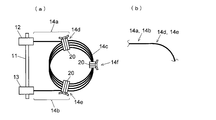
- the top view which shows the state of the deaeration tube in the deaeration apparatus of a present Example.
- Schematic which shows arrangement
- FIG. 1 is a configuration diagram of a deaeration device and its surroundings when the deaeration device of this embodiment is used in a liquid chromatograph
- FIG. 2 is a plan view showing a state of a deaeration tube in the degassing device of this embodiment. .
- the deaeration device 1 of the present embodiment includes a box-shaped vacuum chamber 10 that can be sealed, a vacuum channel 15 having one end connected to the vacuum chamber 10, and a vacuum pump 16 provided on the vacuum channel 15. And a pressure sensor 17 connected to the vacuum flow path 15 between the vacuum chamber 10 and the vacuum pump 16.
- the chamber lid portion 11 constituting one wall surface of the vacuum chamber 10 includes two flow path connection portions 12 and 13 for connecting the flow path inside the vacuum chamber 10 and the external flow path.
- the deaeration tube 14 made of a gas permeable material that allows gas to pass but prevents liquid from passing is housed in the vacuum chamber 10 in a state of being wound around a plurality of loops as shown in FIG. Both ends thereof are connected to the flow path connecting portions 12 and 13.
- one flow path connection portion 12 is connected to the other end of the mobile phase introduction flow path 3, one end of which is connected to the mobile phase container 2 in which the mobile phase is stored.
- One end of the mobile phase derivation flow path 4 reaching the liquid feed pump 5 is connected to the path connection portion 13. That is, the mobile phase introduction flow path 3 and the deaeration tube 14 are connected via the flow path connection part 12, and the degassing tube 14 and the mobile phase derivation flow path 4 are connected via the flow path connection part 13. Yes.
- the valve for switching a mobile phase is inserted between the deaeration apparatus 1 and the liquid feeding pump 5.
- the deaeration tube 14 desirably has high gas permeability, and as a material, for example, PTFE-based synthetic resin, more specifically, Teflon (registered trademark) AF manufactured by DuPont is suitable.
- PTFE-based synthetic resin more specifically, Teflon (registered trademark) AF manufactured by DuPont is suitable.
- one deaeration tube 14 in a state of being housed in the vacuum chamber 10 includes a loop-shaped portion 14c wound in a loop shape, and one ends of the flow-path connecting portions 12, 13 respectively. And linear portions 14a and 14 that extend substantially linearly and reach the loop-shaped portion 14c.
- the loop-shaped portion 14c may be formed by simply winding the deaeration tube 14, but the tube material has thermoplasticity, so the loop-shaped portion 14c may be formed by thermoforming.
- the plurality of tubes constituting the loop-shaped portion 14c of the deaeration tube 14 are bound together by fluororesin tape at three portions in the circumferential direction. That is, as shown in FIG. 2, two portions 14d and 14e that start to bend from the straight portions 14a and 14b and enter the loop portion 14c, and a portion 14f that is farthest from the chamber lid portion 11 by the loop portion 14c
- the bundling portion 20 is formed by bundling and tying a plurality of tubes with a fluororesin tape at these three locations.
- the fluororesin tape used at this time is softer than the material of the degassing tube 14, so that even if the fluororesin tape is tied up to some extent, the tube will not be deformed, crushed or constricted.
- the plurality of tubes are almost integrated.
- the mobile phase in the mobile phase container 2 flows through the mobile phase introduction channel 3 and flows into the deaeration tube 14 in the vacuum chamber 10 of the deaeration device 1 and moves. It flows into the liquid feed pump 5 through the phase lead-out flow path 4.
- the mobile phase that has passed through the degassing tube 14 of the degassing apparatus 1 reaches the valve.
- the space in the vacuum chamber 10 is decompressed by a vacuum pump 16, and the gas dissolved in the mobile phase passing through the degassing tube 14 passes through the wall surface of the degassing tube 14 and is taken out to the vacuum chamber 10 side. It exhausts through the vacuum flow path 15. This removes gas from the mobile phase.
- the mobile phase in the deaeration tube 14 is increased or decreased by driving the liquid feeding pump 5, or if the flow of the mobile phase becomes intermittent by switching the valve, the mobile phase becomes unstable.
- a force acts on the deaeration tube 14 by the flow.
- the loop-shaped part 14c of the deaeration tube 14 is bundled by the three binding parts 20 as described above, it is less likely to bend compared to a state where a plurality of tubes are separated. Therefore, even if force acts, it is hard to rock
- the plurality of tubes move substantially in the same manner even when swinging, it is possible to prevent the contacting tubes from rubbing and to reduce wear of the tubes. As a result, it is possible to prevent the tube wall surface from becoming thin and to avoid the occurrence of cracks that lead to liquid leakage.
- the bundling portion 20 is formed by bundling and binding a plurality of tubes using a fluororesin tape.
- a plurality of tubes may be bundled or integrated by other methods at the bundling portion 20 position. May be.
- a degassing tube is inserted into a shrinkable tube member that contracts due to some physical stimulus, such as a heat collection tube, and the degassed tube is made into a loop and then given a stimulus such as heat to the shrinkable tube member.
- the tube member may be contracted to bind a plurality of deaeration tubes.
- the plurality of degassing tubes are bonded or adhered to each other at the position of the binding portion 20 using an adhesive or a pressure sensitive adhesive. Also good.
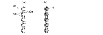
- FIG. 3 is a plan view showing an example of such a tube holding member 30.
- the tube holding member 30 has a configuration in which a plurality of substantially C-shaped clamp portions 30a each capable of holding a single deaeration tube are connected by a connecting portion 30b.
- a tube holding member 30 When such a tube holding member 30 is used, even in a portion where a plurality of deaeration tubes are held by the tube holding member 30, adjacent deaeration tubes do not completely adhere to each other, and a certain space is secured therebetween. In the portion where the adjacent deaeration tubes are in close contact with each other in the loop-shaped portion 14c, the gas is difficult to escape from the tube, which is disadvantageous in terms of deaeration efficiency.
Landscapes
- Chemical & Material Sciences (AREA)
- Chemical Kinetics & Catalysis (AREA)
- Engineering & Computer Science (AREA)
- Water Supply & Treatment (AREA)
- Degasification And Air Bubble Elimination (AREA)
- Separation Using Semi-Permeable Membranes (AREA)
Abstract
気-液分離膜を用いた減圧方式の脱気装置において、真空チャンバ内に配設される脱気チューブ(14) の両端部はチャンバ蓋部(11)に設けられた流路接続部(12、13)に接続され、ループ状に巻回された状態で真空チャンバ内に収納されている。脱気チューブ(14)のループ状部(14c)の三箇所で、複数の脱気チューブ(14)は該チューブを構成する気体透過性材料よりも柔らかいフッ素樹脂テープにより束ねられて結束されている。これにより、脱気チューブ(14)中の移動相の流れに強弱が生じたり流れが間欠的になったりした場合でも、脱気チューブ(14)は揺動しにくく、揺動してもチューブ同士の擦れを防止することができる。その結果、脱気チューブ(14)が摩耗によって薄くなることを防止でき、液漏れの要因となるクラックの発生を回避することができる。
Description
本発明は、液体中に溶存している気体や気泡を除去するための脱気装置に関し、さらに詳しくは、液体クロマトグラフの移動相から気体や気泡を除去するのに好適である、気-液分離膜を用いた減圧脱気方式による脱気装置に関する。
一般に液体クロマトグラフでは、移動相容器に貯留された移動相が送液ポンプにより吸引され、試料インジェクタを介してカラムに送給される。所定のタイミングで試料インジェクタから移動相中に試料液が注入されると、該試料液は移動相に押されてカラムに導入され、カラムを通過する間に試料液中の各種成分が時間方向に分離されてカラム出口から溶出する。その溶出液に含まれる成分が例えばフォトダイオードアレイ(PDA)検出器などの検出器により検出され、それぞれの成分の濃度に応じた検出信号が得られる。この検出信号に基づいて、時間経過に伴う信号強度の変化を示すクロマトグラムが作成される。
こうした液体クロマトグラフにおいて、送液ポンプにより高圧で送給される移動相中に気体(空気等)が多く含まれていてカラムや検出器セル内で気泡が発生すると、クロマトグラムにおけるピークの変形やスパイクノイズ等の発生の要因となる。また、検出器に到達する移動相に溶解している気体(主として酸素)の量が変化すると、クロマトグラムにおけるベースラインの変動やドリフトなどの要因となる。さらにまた、移動相容器内での気泡発生などによって送液ポンプに気泡が送り込まれると、該ポンプでの送液不良が起こり、ピークの保持時間の変動などをもたらすことがある。そこで、このような分析結果への悪影響を軽減するために、従来の液体クロマトグラフでは、移動相中の溶存ガスや気泡を除去する脱気装置が、移動相容器と送液ポンプとの間の流路に設けられている。
脱気にはいくつかの方式があるが、気-液分離膜を用いた減圧脱気方式は広く使用されている方式の一つである。特許文献1、2、非特許文献1などに記載されているように、この方式による脱気装置(以下、気-液分離膜を用いた減圧脱気方式による脱気装置を単に脱気装置という)は、真空ポンプにより真空排気される(つまり減圧される)真空チャンバ内に、気体を通過させる一方、液体を通さない気体透過性材料(例えばPTFE(Polytetrafluoroethylene)系の合成樹脂)からなる脱気チューブを備える。移動相容器から吸引した移動相をこの脱気チューブ内に流通させると、移動相中の溶存気体は脱気チューブの気体透過性材料である壁面を通して真空雰囲気中に取り出され、それによって移動相中の気体は除去される。
上記脱気装置では、脱気チューブ内壁面と移動相との接触面積が大きいほど脱気効率が高い。この接触面積を大きくするには脱気チューブを長くすればよいが、そうすると流路抵抗が大きくなり、送液ポンプの送液能力を上げる必要が生じる。そこで、送液圧力に耐えうる範囲で極力チューブの壁面を薄くすることで、同じ外径サイズに対し内径サイズを大きくして流路断面積を増やし、流路抵抗を下げるような工夫がなされている。また、真空ポンプの負荷を小さくして、例えば低い性能の真空ポンプで十分な減圧を達成するには、真空チャンバの内容積は小さいほうが好ましい。そのため、図4に示したように、長い脱気チューブ14がループ状に巻回されて小さなサイズの真空チャンバ10内に収納される構成が採られている。これにより、装置の小型化を図りつつ、高い脱気性能を達成することができる。
なお、低圧グラジエント分析を行う場合は、それぞれ異なる移動相が貯留されている複数の移動相容器と、複数の移動相を混合するバルブとの間の複数の流路に、上述したような脱気装置がそれぞれ配置される。
「移動相の脱気 5.脱気方法 5-4)気-液分離膜を用いた減圧脱気」、株式会社島津製作所、[2014年7月25日検索]、インターネット<URL:http://www.an.shimadzu.co.jp/hplc/support/lib/lctalk/s5/054.htm>
しかしながら、上述した従来の脱気装置では、それほど長時間使用したわけではないにも拘わらず、脱気チューブにクラックが発生して液漏れが生じ、測定が途中でできなくなることがあるという問題があった。
本発明はこうした課題に鑑みて成されたものであり、その目的とするところは、脱気チューブのクラックの発生を防止することで、液漏れが起こるのを回避することができる脱気装置を提供することにある。
本発明者は、脱気チューブにクラックが発生する原因を究明するために実験を繰り返し、以下のようなクラック発生のメカニズムを解明した。
即ち、送液ポンプの吸引作用によって脱気チューブ中を移動相が流れる際に、その流れには強弱(つまり脈流)が生じることがある。また、特に低圧グラジエント分析では、移動相を混合するためのバルブの頻繁な切り替えによって、脱気チューブ中の移動相の流れが一旦停止し再び流れるという間欠的な流れを短いサイクルで繰り返す現象が起こることがよくある。こうした現象が起こった場合、それに伴って脱気チューブは真空チャンバ内で揺動することが判明した。そして、その揺動によって、ループ状部で隣り合うチューブ同士が擦れたり、或いは、チューブと真空チャンバ内壁面とが擦れたりすることで、脱気チューブの一部が摩耗して薄くなることがあることも判明した。こうした摩耗が進行して肉厚が薄くなった脱気チューブは送液圧力に耐えられなくなり、その結果、脱気チューブにクラックが生じることになる。
上記のクラック発生のメカニズムから、これを防止するには、脱気チューブの揺動を抑えることが有効であることが分かる。本発明はこうした知見に基づいてなされたものである。
即ち、送液ポンプの吸引作用によって脱気チューブ中を移動相が流れる際に、その流れには強弱(つまり脈流)が生じることがある。また、特に低圧グラジエント分析では、移動相を混合するためのバルブの頻繁な切り替えによって、脱気チューブ中の移動相の流れが一旦停止し再び流れるという間欠的な流れを短いサイクルで繰り返す現象が起こることがよくある。こうした現象が起こった場合、それに伴って脱気チューブは真空チャンバ内で揺動することが判明した。そして、その揺動によって、ループ状部で隣り合うチューブ同士が擦れたり、或いは、チューブと真空チャンバ内壁面とが擦れたりすることで、脱気チューブの一部が摩耗して薄くなることがあることも判明した。こうした摩耗が進行して肉厚が薄くなった脱気チューブは送液圧力に耐えられなくなり、その結果、脱気チューブにクラックが生じることになる。
上記のクラック発生のメカニズムから、これを防止するには、脱気チューブの揺動を抑えることが有効であることが分かる。本発明はこうした知見に基づいてなされたものである。
即ち、上記課題を解決するためになされた本発明は、真空排気されるチャンバと、該チャンバ内に収納され、その両端が該チャンバに対して固定された接続部によりそれぞれ保持されるとともに、2周以上ループ状に巻回されたループ状部を有し、気体を通す一方、液体を通さない気体透過性材料からなる脱気チューブと、を具備し、前記脱気チューブ中を流通する液体に含まれる気体を該脱気チューブの壁面を通して該脱気チューブ外に取り出して排出する脱気装置において、
前記脱気チューブの前記ループ状部の揺動を抑制する揺動抑制手段を備えることを特徴としている。
前記脱気チューブの前記ループ状部の揺動を抑制する揺動抑制手段を備えることを特徴としている。
本発明に係る脱気装置の一態様として、前記揺動抑制手段は、少なくとも前記ループ状部の一部で複数本のチューブを一体化するものとすることができる。
より具体的には、前記揺動抑制手段は例えば、複数本のチューブをまとめて縛る紐状又はシート状の結束部材とすることができる。また、例えば複数本のチューブを挿通することが可能な筒状体であって、熱や光、又はそれ以外の物理的刺激などによって収縮することで複数本のチューブを束ねることができる結束部材を用いることもできる。さらにまた、前記揺動抑制手段は、チューブの外壁面の一部同士を貼り付ける接着剤や粘着剤などにより複数本のチューブを一体化する結合部材でもよい。
いずれにしても、複数本の脱気チューブがループ状部の一部において一体化されることによって、該ループ状部を構成する各チューブの自由な動きが拘束を受ける。また、一本一本のチューブは撓み易くても、複数本のチューブが一体化されることで撓みが生じにくくなる。それによって、脱気チューブ中の液体の流れが脈流となったり間欠的になったりした場合であっても、各チューブの自由な揺動は殆ど生じなくなり、チューブ全体の揺動も抑制される。その結果、脱気チューブ同士の擦れが防止できるととともに、脱気チューブが真空チャンバの内壁面に接触している場合でも両者の擦れはかなり軽減でき、不所望の摩擦によって脱気チューブの肉厚が薄くなることを防止することができる。
脱気チューブの揺動を抑制するために結束部材等により複数のチューブを一体化する場合、前記脱気チューブにあって、前記接続部に保持された該脱気チューブの両端部から前記ループ状部にまで直線状に延伸したあと屈曲し始める二つの部位と、それ以外の前記ループ状部の少なくとも一箇所との三箇所以上の部位で、複数本のチューブを一体化することが好ましい。
脱気チューブが揺動するとき、端部が固定された直線部状部とループ状部との境界部分には最も力が掛かりクラックが生じ易いが、上記構成によれば、その部位の揺動が抑制されるので、クラックの発生を効果的に防止することができる。
脱気チューブが揺動するとき、端部が固定された直線部状部とループ状部との境界部分には最も力が掛かりクラックが生じ易いが、上記構成によれば、その部位の揺動が抑制されるので、クラックの発生を効果的に防止することができる。
なお、脱気チューブの揺動を抑えるには、一体化する部位の数を増やすほうがよいが、通常、そうした部位では脱気チューブの壁面を通しての気体の透過性が低下する(又は殆どゼロになる)ので、一体化する部位は3程度にとどめるほうがよい。
また、上記結束部材が複数本のチューブを縛る部材である場合、該結束部材は前記脱気チューブを構成する気体透過性材料よりも柔らかく且つ耐薬品性を有する材料からなることが好ましい。
これによって、仮に縛り方が強くても脱気チューブが変形したり潰れたりすることがなく、該チューブ中の流路を確保することができる。また、脱気チューブの壁面を通して取り出される気体が腐食性のガス等であった場合でも、結束部材が損傷を受けて結束が解除されてしまうことを回避することができる。
これによって、仮に縛り方が強くても脱気チューブが変形したり潰れたりすることがなく、該チューブ中の流路を確保することができる。また、脱気チューブの壁面を通して取り出される気体が腐食性のガス等であった場合でも、結束部材が損傷を受けて結束が解除されてしまうことを回避することができる。
また本発明に係る脱気装置の他の態様として、
前記揺動抑制部材は、少なくとも前記ループ状部の一部で複数本のチューブのそれぞれの隣接間隔を保つように各チューブを独立に保持する保持部材である構成とすることができる。
保持部材は例えば、各チューブを保持する略C字状の保持部が複数連結された部材である。
前記揺動抑制部材は、少なくとも前記ループ状部の一部で複数本のチューブのそれぞれの隣接間隔を保つように各チューブを独立に保持する保持部材である構成とすることができる。
保持部材は例えば、各チューブを保持する略C字状の保持部が複数連結された部材である。
ループ状部においてチューブ同士が密着すると、その密着部分ではチューブ内からの気体の取り出しが行えなくなり、脱気効率の低下に繋がるおそれがある。これに対し、上記態様によれば、ループ状部において隣接するチューブ同士が密着せず、或る程度の間隔を保つことができる。それによって、高い脱気効率を確保しつつ揺動を抑制することができる。
なお、脱気チューブのループ状部は、熱成型等によって巻回された形状に成型されていてもよいし、そうした成型がなされることなく、揺動抑制手段である結束部材等によって結束されることで巻回した状態が維持されるものであってもよい。
本発明に係る脱気装置によれば、脱気チューブ中の液体の流れが脈流となったり間欠的になったりした場合でも、脱気チューブ同士の擦れや、脱気チューブと真空チャンバ内壁面との擦れを防止又は軽減することができる。それによって、不所望の摩擦により脱気チューブの肉厚が薄くなることを防止することができるので、脱気チューブにクラックが発生することを回避し、液漏れを防止することができる。
以下、本発明に係る脱気装置の一実施例について、添付図面を参照して説明する。
図1は本実施例の脱気装置を液体クロマトグラフに用いる場合における脱気装置及びその周辺の構成図、図2は本実施例の脱気装置における脱気チューブの状態を示す平面図である。
図1は本実施例の脱気装置を液体クロマトグラフに用いる場合における脱気装置及びその周辺の構成図、図2は本実施例の脱気装置における脱気チューブの状態を示す平面図である。
本実施例の脱気装置1は、密閉可能な箱状の真空チャンバ10と、該真空チャンバ10に一端が接続された真空流路15と、該真空流路15上に設けられた真空ポンプ16と、真空チャンバ10と真空ポンプ16との間の真空流路15に接続された圧力センサ17と、を備える。真空チャンバ10の一つの壁面を構成するチャンバ蓋部11は、真空チャンバ10の内部の流路と外部の流路とを接続するための二つの流路接続部12、13を備える。気体を通過させる一方、液体の通過を阻止する気体透過性材料からなる脱気チューブ14は、既出の図4に示したようにループ状に複数周巻回された状態で真空チャンバ10内に収納され、その両端が上記流路接続部12、13に接続されている。
真空チャンバ10の外側において、一方の流路接続部12には、移動相が貯留されている移動相容器2に一端が接続された移動相導入流路3の他端が接続され、他方の流路接続部13には、送液ポンプ5に至る移動相導出流路4の一端が接続されている。即ち、流路接続部12を介して移動相導入流路3と脱気チューブ14とが接続され、流路接続部13を介して脱気チューブ14と移動相導出流路4とが接続されている。なお、低圧グラジエント分析を行う際には、脱気装置1と送液ポンプ5との間に移動相を切り替えるためのバルブが挿設される。
脱気チューブ14は高い気体透過性を有することが望ましく、材料としては例えばPTFE系の合成樹脂、より具体的には、デュポン社製のテフロン(登録商標)AFなどが好適である。
図2に示すように、真空チャンバ10内に収納されている状態の1本の脱気チューブ14は、ループ状に巻回されたループ状部14cと、それぞれ一端が流路接続部12、13に接続され、ほぼ直線状に延伸してループ状部14cに至る直線状部14a、14とからなる。ループ状部14cは脱気チューブ14を単に巻回することで形成したものでもよいが、チューブ材料は熱可塑性を有しているので、熱成型によってループ状部14cを形成してもよい。
脱気チューブ14のループ状部14cを構成している複数本のチューブは、周方向に三つの部位においてそれぞれフッ素樹脂テープにより結束されている。即ち、図2に示すように、直線状部14a、14bからループ状部14cに入って屈曲し始める二つの部位14d、14eと、ループ状部14cでチャンバ蓋部11から最も離れた部位14fとの三箇所で複数本のチューブがフッ素樹脂テープにより束ねて縛られることで結束部20が形成されている。このときに用いられるフッ素樹脂テープは、脱気チューブ14の材料に比べて柔らかい樹脂であるため、フッ素樹脂テープを或る程度強く縛っても、チューブが変形したり潰れたり或いは括れたりすることなく、結束部20において複数のチューブはまとまってほぼ一体となる。
測定実行時に送液ポンプ5が駆動されると、移動相容器2中の移動相は移動相導入流路3を経て、脱気装置1の真空チャンバ10内の脱気チューブ14中に流れ、移動相導出流路4を経て送液ポンプ5に流入する。また、低圧グラジエント分析の場合には、脱気装置1の脱気チューブ14中を通過した移動相はバルブに至る。真空チャンバ10内の空間は真空ポンプ16によって減圧されており、脱気チューブ14中を通る移動相に溶存している気体は脱気チューブ14の壁面を透過して真空チャンバ10側へ取り出され、真空流路15を経て排気される。これにより、移動相から気体が除去される。
このとき、送液ポンプ5の駆動によって脱気チューブ14中の移動相の流れに強弱が生じたり、或いはバルブの切替えによって移動相の流れが間欠的になったりすると、その移動相の不安定な流れによって脱気チューブ14には力が作用する。しかしながら、上述したように脱気チューブ14のループ状部14cは三箇所の結束部20で束ねられているため、複数本のチューブがばらばらである状態に比べて撓みにくくなっている。そのため、力が作用しても揺動しにくく、その振幅は大きく抑制される。また、揺動する場合でも複数本のチューブがほぼ同じように動くため、接触しているチューブ同士が擦れることを抑えることができ、チューブの摩耗を軽減することができる。その結果、チューブ壁面が薄くなることを防止して、液漏れに繋がるクラックの発生も回避することができる。
上記実施例では、フッ素樹脂テープを用いて複数のチューブを束ねて縛ることで結束部20を形成していたが、結束部20の位置において他の方法で複数のチューブを束ねたり一体化したりしてもよい。例えば、熱収集チューブ等、何らかの物理的刺激によって収縮する収縮性チューブ部材に脱気チューブを挿通し、該脱気チューブをループ状としたあとに収縮性チューブ部材に熱などの刺激を与えて該チューブ部材を収縮させて複数本の脱気チューブを結束してもよい。
また、複数本の脱気チューブを束ねて一体化するのではなく、接着剤や粘着剤などを用いて複数本の脱気チューブを上記結束部20の位置において相互に接着又は粘着させるようにしてもよい。
また、複数本の脱気チューブを束ねて一体化するのではなく、接着剤や粘着剤などを用いて複数本の脱気チューブを上記結束部20の位置において相互に接着又は粘着させるようにしてもよい。
さらにまた、移動相が流れる際の揺動を抑えるために、ループ状部14cにおいて複数本の脱気チューブをそれぞれ独立に保持するチューブ保持部材を用いてもよい。図3はこうしたチューブ保持部材30の一例を示す平面図である。
このチューブ保持部材30は、それぞれが一本の脱気チューブを保持可能な略C字型の複数のクランプ部30aが連結部30bで連結された構成を有する。こうしたチューブ保持部材30を用いると、このチューブ保持部材30で複数の脱気チューブを保持する部位においても、隣接する脱気チューブが完全には密着せず、その間に一定の空間が確保される。ループ状部14cにおいて隣接する脱気チューブが密着した部分では気体がチューブ内から抜けにくいため、脱気効率の点で不利である。これに対し、このようなチューブ保持部材30を用いて隣接する脱気チューブの間隔を確保することで、全体の揺動を抑えてチューブ同士の擦れを防止するとともに、脱気効率を高めることができる。
また、上記実施例は本発明の一例であり、本発明の趣旨に沿った範囲で適宜変形や修正、追加を行っても本願特許請求の範囲に包含されることは明らかである。
1…脱気装置1
2…移動相容器
3…移動相導入流路
4…移動相導出流路
5…送液ポンプ
10…真空チャンバ
11…チャンバ蓋部
12、13…流路接続部
14…脱気チューブ
14a、14b…直線状部
14c…ループ状部
15…真空流路
16…真空ポンプ
17…圧力センサ
2…移動相容器
3…移動相導入流路
4…移動相導出流路
5…送液ポンプ
10…真空チャンバ
11…チャンバ蓋部
12、13…流路接続部
14…脱気チューブ
14a、14b…直線状部
14c…ループ状部
15…真空流路
16…真空ポンプ
17…圧力センサ
Claims (8)
- 真空排気されるチャンバと、該チャンバ内に収納され、その両端が該チャンバに対して固定された接続部によりそれぞれ保持されるとともに、2周以上ループ状に巻回されたループ状部を有し、気体を通す一方、液体を通さない気体透過性材料からなる脱気チューブと、を具備し、前記脱気チューブ中を流通する液体に含まれる気体を該脱気チューブの壁面を通して該脱気チューブ外に取り出して排出する脱気装置において、
前記脱気チューブの前記ループ状部の揺動を抑制する揺動抑制手段を備えることを特徴とする脱気装置。 - 請求項1に記載の脱気装置であって、
前記揺動抑制手段は、少なくとも前記ループ状部の一部で複数本のチューブを一体化するものであることを特徴とする脱気装置。 - 請求項2に記載の脱気装置であって、
前記揺動抑制手段は、複数本のチューブをまとめて縛る紐状又はシート状の結束部材であることを特徴とする脱気装置。 - 請求項2に記載の脱気装置であって、
前記揺動抑制手段は、複数本のチューブを挿通することが可能な筒状体であって、熱、光、又はそれ以外の物理的刺激によって収縮することで複数本のチューブを束ねることができる結束部材であることを特徴とする脱気装置。 - 請求項2に記載の脱気装置であって、
前記揺動抑制手段は、チューブの外壁面の一部同士を貼り付ける接着剤又は粘着剤により複数本のチューブを一体化する結合部材であることを特徴とする脱気装置。 - 請求項2~5のいずれかに記載の脱気装置であって、
前記脱気チューブにあって、前記接続部に保持された該脱気チューブの両端部から前記ループ状部にまで直線状に延伸したあと屈曲し始める二つの部位と、それ以外の前記ループ状部の少なくとも一箇所との三箇所以上の部位で、複数本のチューブを一体化することを特徴とする脱気装置。 - 請求項3又は4に記載の脱気装置であって、
前記結束部材は前記脱気チューブを構成する気体透過性材料よりも柔らかく且つ耐薬品性を有する材料からなることを特徴とする脱気装置。 - 請求項1に記載の脱気装置であって、
前記揺動抑制部材は、少なくとも前記ループ状部の一部で複数本のチューブのそれぞれの隣接間隔を保つように各チューブを独立に保持する保持部材であることを特徴とする脱気装置。
Priority Applications (1)
| Application Number | Priority Date | Filing Date | Title |
|---|---|---|---|
| PCT/JP2014/069938 WO2016016946A1 (ja) | 2014-07-29 | 2014-07-29 | 脱気装置 |
Applications Claiming Priority (1)
| Application Number | Priority Date | Filing Date | Title |
|---|---|---|---|
| PCT/JP2014/069938 WO2016016946A1 (ja) | 2014-07-29 | 2014-07-29 | 脱気装置 |
Publications (1)
| Publication Number | Publication Date |
|---|---|
| WO2016016946A1 true WO2016016946A1 (ja) | 2016-02-04 |
Family
ID=55216892
Family Applications (1)
| Application Number | Title | Priority Date | Filing Date |
|---|---|---|---|
| PCT/JP2014/069938 Ceased WO2016016946A1 (ja) | 2014-07-29 | 2014-07-29 | 脱気装置 |
Country Status (1)
| Country | Link |
|---|---|
| WO (1) | WO2016016946A1 (ja) |
Cited By (2)
| Publication number | Priority date | Publication date | Assignee | Title |
|---|---|---|---|---|
| US20200217869A1 (en) * | 2017-01-05 | 2020-07-09 | Illumina, Inc. | Flow cell liquid degassing system and method |
| JPWO2024004829A1 (ja) * | 2022-06-27 | 2024-01-04 |
Citations (5)
| Publication number | Priority date | Publication date | Assignee | Title |
|---|---|---|---|---|
| JPS54123785A (en) * | 1978-02-24 | 1979-09-26 | Du Pont | Deaerator |
| JPS6227703U (ja) * | 1985-07-31 | 1987-02-19 | ||
| JPH03157105A (ja) * | 1989-11-16 | 1991-07-05 | Chisso Corp | 液体脱気装置用気体透過部材及びその製造方法 |
| JP2003047803A (ja) * | 2001-07-10 | 2003-02-18 | Systec Inc | 脱気および脈動減少装置の応用例におけるバードイン配管 |
| WO2008035714A1 (en) * | 2006-09-22 | 2008-03-27 | Nitto Denko Corporation | Gas removal device |
-
2014
- 2014-07-29 WO PCT/JP2014/069938 patent/WO2016016946A1/ja not_active Ceased
Patent Citations (5)
| Publication number | Priority date | Publication date | Assignee | Title |
|---|---|---|---|---|
| JPS54123785A (en) * | 1978-02-24 | 1979-09-26 | Du Pont | Deaerator |
| JPS6227703U (ja) * | 1985-07-31 | 1987-02-19 | ||
| JPH03157105A (ja) * | 1989-11-16 | 1991-07-05 | Chisso Corp | 液体脱気装置用気体透過部材及びその製造方法 |
| JP2003047803A (ja) * | 2001-07-10 | 2003-02-18 | Systec Inc | 脱気および脈動減少装置の応用例におけるバードイン配管 |
| WO2008035714A1 (en) * | 2006-09-22 | 2008-03-27 | Nitto Denko Corporation | Gas removal device |
Cited By (3)
| Publication number | Priority date | Publication date | Assignee | Title |
|---|---|---|---|---|
| US20200217869A1 (en) * | 2017-01-05 | 2020-07-09 | Illumina, Inc. | Flow cell liquid degassing system and method |
| JPWO2024004829A1 (ja) * | 2022-06-27 | 2024-01-04 | ||
| WO2024004829A1 (ja) * | 2022-06-27 | 2024-01-04 | Dic株式会社 | 脱気装置 |
Similar Documents
| Publication | Publication Date | Title |
|---|---|---|
| US8177889B2 (en) | Gas removal device | |
| Erans et al. | Calcium looping sorbents for CO2 capture | |
| US8784630B2 (en) | Sample stacking method using on-line automatic solid phase extraction coupled to nonaqueous capillary electrophoresis and interface structure between solid-phase preconcentration cartridge and capillary therefor | |
| WO2016016946A1 (ja) | 脱気装置 | |
| KR101486192B1 (ko) | 기밀성과 정렬성능 향상한 플랜지 배관 연결용 가스켓 | |
| FR2965888B1 (fr) | Canalisation d'evacuation de gaz et procede d'evacuation associe | |
| RU2012120426A (ru) | Соединитель для трубопровода для текучей среды и трубопровод для текучей среды | |
| RU2012155154A (ru) | Трубный зажим с присоединительным элементом | |
| CN104781665A (zh) | 配管连结接头 | |
| KR101270316B1 (ko) | 탈기 장치 | |
| US9061247B2 (en) | Separation membrane module | |
| US9110072B2 (en) | Assembly of a cartridge and a cartridge clamp, and a cartridge clamp for use in such an assembly | |
| RU2009135002A (ru) | Пробирка для упаковки заданного объема биологической субстанции с низкой температурой хранения и содержащая ее система | |
| EP2184784A3 (en) | Photoelectric sensor housing assembling method and photoelectric sensor | |
| JP6334575B2 (ja) | フレキシブルな容器とこの種のフレキシブルな容器用の充填装置及びそれに応じた充填方法 | |
| KR20210021401A (ko) | 의약품 또는 생물학적 매체를 저장하는 시스템 및 방법 | |
| EA201170111A1 (ru) | Система и способ для наполнения контейнеров складного типа | |
| US20150377390A1 (en) | Piping component and pipe | |
| JP6646499B2 (ja) | 脱気装置 | |
| CN201934765U (zh) | 一种多层金属膜片敏感装置 | |
| JP2017508677A (ja) | 化学溶液収容瓶及びその製造方法 | |
| JP2019506339A (ja) | 二つの柔軟性を有するチューブ状容器を接続する方法 | |
| JPWO2017033914A1 (ja) | 液体クロマトグラフィー用カラム及びそれを備えた液体クロマトグラフ装置 | |
| JP6881474B2 (ja) | 分析装置用の配管デバイス及びその配管デバイスを用いた分析装置 | |
| JP2008196868A (ja) | 汚染防止輸液チューブ |
Legal Events
| Date | Code | Title | Description |
|---|---|---|---|
| 121 | Ep: the epo has been informed by wipo that ep was designated in this application |
Ref document number: 14898880 Country of ref document: EP Kind code of ref document: A1 |
|
| NENP | Non-entry into the national phase |
Ref country code: DE |
|
| NENP | Non-entry into the national phase |
Ref country code: JP |
|
| 122 | Ep: pct application non-entry in european phase |
Ref document number: 14898880 Country of ref document: EP Kind code of ref document: A1 |