WO2016013636A1 - トロカール,ポート,手術支援システム - Google Patents
トロカール,ポート,手術支援システム Download PDFInfo
- Publication number
- WO2016013636A1 WO2016013636A1 PCT/JP2015/071030 JP2015071030W WO2016013636A1 WO 2016013636 A1 WO2016013636 A1 WO 2016013636A1 JP 2015071030 W JP2015071030 W JP 2015071030W WO 2016013636 A1 WO2016013636 A1 WO 2016013636A1
- Authority
- WO
- WIPO (PCT)
- Prior art keywords
- trocar
- camera
- pipe
- image
- pipe portion
- Prior art date
- Legal status (The legal status is an assumption and is not a legal conclusion. Google has not performed a legal analysis and makes no representation as to the accuracy of the status listed.)
- Ceased
Links
Images











Classifications
-
- A—HUMAN NECESSITIES
- A61—MEDICAL OR VETERINARY SCIENCE; HYGIENE
- A61B—DIAGNOSIS; SURGERY; IDENTIFICATION
- A61B1/00—Instruments for performing medical examinations of the interior of cavities or tubes of the body by visual or photographical inspection, e.g. endoscopes; Illuminating arrangements therefor
- A61B1/04—Instruments for performing medical examinations of the interior of cavities or tubes of the body by visual or photographical inspection, e.g. endoscopes; Illuminating arrangements therefor combined with photographic or television appliances
- A61B1/046—Instruments for performing medical examinations of the interior of cavities or tubes of the body by visual or photographical inspection, e.g. endoscopes; Illuminating arrangements therefor combined with photographic or television appliances for infrared imaging
-
- A—HUMAN NECESSITIES
- A61—MEDICAL OR VETERINARY SCIENCE; HYGIENE
- A61B—DIAGNOSIS; SURGERY; IDENTIFICATION
- A61B1/00—Instruments for performing medical examinations of the interior of cavities or tubes of the body by visual or photographical inspection, e.g. endoscopes; Illuminating arrangements therefor
-
- A—HUMAN NECESSITIES
- A61—MEDICAL OR VETERINARY SCIENCE; HYGIENE
- A61B—DIAGNOSIS; SURGERY; IDENTIFICATION
- A61B1/00—Instruments for performing medical examinations of the interior of cavities or tubes of the body by visual or photographical inspection, e.g. endoscopes; Illuminating arrangements therefor
- A61B1/04—Instruments for performing medical examinations of the interior of cavities or tubes of the body by visual or photographical inspection, e.g. endoscopes; Illuminating arrangements therefor combined with photographic or television appliances
- A61B1/043—Instruments for performing medical examinations of the interior of cavities or tubes of the body by visual or photographical inspection, e.g. endoscopes; Illuminating arrangements therefor combined with photographic or television appliances for fluorescence imaging
-
- A—HUMAN NECESSITIES
- A61—MEDICAL OR VETERINARY SCIENCE; HYGIENE
- A61B—DIAGNOSIS; SURGERY; IDENTIFICATION
- A61B17/00—Surgical instruments, devices or methods
- A61B17/02—Surgical instruments, devices or methods for holding wounds open, e.g. retractors; Tractors
-
- A—HUMAN NECESSITIES
- A61—MEDICAL OR VETERINARY SCIENCE; HYGIENE
- A61B—DIAGNOSIS; SURGERY; IDENTIFICATION
- A61B17/00—Surgical instruments, devices or methods
- A61B17/34—Trocars; Puncturing needles
Definitions
- the present invention relates to a trocar and related technology used for laparoscopic surgery. However, when used for thoracoscopic surgery, it is called a port.
- Laparoscopic surgery involves injecting carbon dioxide into the abdominal cavity to inflate the abdominal wall to ensure space and field of view for the procedure. Then, a small hole is made in the abdominal wall, and an instrument called a trocar is inserted. From there, it is common to insert a laparoscope (CCD camera) or forceps as a surgical instrument into a patient's body and perform an operation while observing an image displayed on a monitor with a laparoscope (for example, Patent Document 1). .
- CCD camera laparoscope
- forceps as a surgical instrument into a patient's body and perform an operation while observing an image displayed on a monitor with a laparoscope
- the present invention solves the above-described problems, and aims to eliminate the narrowness of the visual field without impairing the minimal invasiveness in laparoscopic surgery.
- the present invention for solving the above-mentioned problems has a pipe part for inserting a medical instrument into the body and a head part provided continuously on the upper part of the pipe part, and is provided on the abdominal wall via the pipe part.
- a trocar comprising a camera provided on the end face of the pipe (trocar camera).
- a light source provided on the end surface of the pipe portion.
- the pipe portion has a knob portion in the circumferential direction of the end surface, and the camera is provided in the knob portion.
- the end face of the pipe part is formed in a shape obtained by obliquely cutting a cylinder, and the camera is provided at the rear end of the slope.
- the camera has a zoom function.
- the medical instrument is a forceps.
- the surgical operation support system of the present invention includes a laparoscope having the trocar, a camera and a position marker, a position detection sensor for detecting the position marker of the laparoscope and the position marker of the trocar, and the position marker.
- An image processing device that estimates the position of the camera based on the position, synthesizes images obtained from the camera based on the position of the camera, and creates a three-dimensional image.
- the surgical operation support system includes a plurality of the trocars described above, a position sensor for detecting the position of the position marker, the position of the camera based on the position of the position marker, and the camera based on the position of the camera. And an image processing apparatus that creates a three-dimensional image by synthesizing the images obtained from the above.
- the surgery support system of the present invention it is preferable to further include a three-dimensional projector provided above the operating table and projecting the three-dimensional image onto the abdomen of the patient.
- a puncture mechanism is further provided.
- the puncture mechanism includes a hinge mechanism provided at the tip of the pipe portion, and a puncture cap provided so as to be able to open and close the end face opening of the pipe portion via the hinge mechanism, and having a pointed tip.
- a cleaning mechanism is further provided.
- the cleaning mechanism is rotatably fixed in the axial direction of the pipe portion, and has a shaft having one end extending outside the trocar, a cleaning member connected to the other end of the shaft, The cleaning member is provided at a normal position where the cleaning member is arranged at a position corresponding to the shape of the end surface of the pipe portion and a cleaning position where the cleaning member is arranged at a position corresponding to the camera. And a switching member for switching between. By the rotation of the switching member, the cleaning member comes into contact with the camera lens for cleaning.
- the present invention is a camera lens cleaning instrument for cleaning the lens of the trocar camera.
- a camera lens cleaning device includes a shaft longer than a trocar pipe length, a holding portion provided at one end of the shaft, and a cleaning member provided at one end of the shaft so as to be smaller than the inner diameter of the pipe and in contact with the camera lens.
- the present invention for solving the above-mentioned problems has a pipe part for inserting a medical instrument into the body and a head part provided continuously on the upper part of the pipe part, and is provided on the abdominal wall via the pipe part.
- the trocar includes an infrared imaging device provided on the end surface of the pipe portion and a near-infrared excitation light source provided on the end surface of the pipe portion that irradiates near-infrared excitation light.
- the surgical operation support system of the present invention includes the trocar described above, and includes ICG fluorescence image acquisition means for acquiring an ICG fluorescence image and visible light image acquisition means for acquiring a visible light image corresponding to the ICG fluorescence image.
- the present invention that solves the above-described problems has a pipe portion for inserting a medical instrument into the body and a head portion that is continuously provided on the upper portion of the pipe portion, and is provided on the chest wall via the pipe portion. It is a port and includes a camera provided on the end surface of the pipe portion.
- the trocar for forceps, a new hole is not made in the abdominal wall, and the low invasiveness is not impaired.
- the narrowness of the visual field can be eliminated.
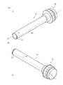
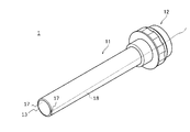
- FIG. 1 is a perspective view of a trocar camera.
- FIG. 1A and FIG. 1B have different viewpoints.
- the trocar 1 includes a pipe part 11 and a head part 12. Most of the pipe portion 11 is inserted into the hole in the abdominal wall.
- the head part 12 is continuously provided on the upper part of the pipe part 11.
- the head portion 12 is hollow, and forceps can be inserted from the top thereof.
- the head unit 12 includes a sealing mechanism that prevents air leakage when the forceps are inserted and removed, and an air supply mechanism that sends air into the abdominal cavity.
- a camera 17 is embedded in the end wall surface of the pipe portion 11 so that the lens is positioned on the end surface 13 of the pipe portion 11.
- a cable 18 is connected to the camera 17, and the cable 18 is inserted through the trocar 1 and connected to an external image processing apparatus 6 (described later).
- the zoom function may be optical zoom or digital zoom.
- a light source 14 is provided on the end surface 13 of the pipe portion 11.
- the light source 14 is, for example, a chip LED.
- a cable 15 (not shown) is connected to the light source 14, and the cable 15 is juxtaposed with the cable 18 and connected to an external power source.
- the field of view is narrow because it is performed only with images obtained from the laparoscope. If a new hole is made in the abdominal wall to insert another camera to enlarge the field of view, the minimally invasiveness is impaired.
- a plurality of cameras 17 can be inserted into the abdominal cavity. Thereby, a visual field can be expanded. Furthermore, since the camera 17 reliably captures the distal end portion of the forceps 4, an important image such as a cut portion can be obtained with certainty.
- the narrowness of the visual field can be eliminated without impairing the minimally invasiveness.
- FIG. 2 is a modification of the trocar camera.
- the conventional pipe portion has a substantially round shape, whereas the present embodiment has a knob portion 16.
- the camera 17 is embedded in the wall surface at the tip of the pipe part 11 and assumes a small camera.
- miniaturization of the camera there is a limit to miniaturization of the camera.
- thickness of the pipe wall there is a possibility that a sufficient space cannot be secured for embedding the camera.
- the space 16 can secure a sufficient space for embedding the camera.
- the knob portion 16 does not become an obstacle to trocar insertion.
- the light source 14 may be provided in the knob portion 16.
- FIG. 3 is a schematic configuration of the surgery support system 101.
- the surgery support system 101 includes a forceps trocar 1a having a camera 17a and a marker 19, a forceps trocar 1b having a camera 17b and a marker 19b, a laparoscopic trocar 3, forceps 4a and 4b, and an abdominal cavity having a marker 19d.
- An image processing device 6 for inputting an image obtained from the mirror 5 and the cameras 17a and 17b and an image obtained from the laparoscope 5 and synthesizing these images to create a three-dimensional image, and an image processing device 6 A three-dimensional monitor 7 for outputting the created three-dimensional image and an optical sensor 9 are provided.
- the forceps 4a and 4b are a kind of surgical instrument, and are used to grasp, restrain, pull, and cut blood vessels and organs. Generally, it has a bowl shape, and the tip is actuated via a fulcrum by the rotation of the handle. The handle portion is closed and inserted into the forceps trocars 1a and 1b. In general, a plurality of (for example, 3 to 5) forceps are used in laparoscopic surgery. In this system, at least one forceps and a forceps trocar are sufficient.
- the laparoscope 5 is a kind of endoscopic instrument, and has a camera and a light source.
- the laparoscope 5 is inserted into the body through the trocar 3 for laparoscope.
- the marker 19d is provided at a position where it is not inserted into the body of the laparoscope 5.
- the optical sensor 9 measures the three-dimensional positions of the markers 19 a, 19 b, 19 d and outputs the measurement results to the image processing device 6.
- the optical sensor 9 recognizes white and black of the marker as visible light, but may transmit infrared and receive infrared reflected by the marker.
- the sensor is not limited to an optical sensor, and may be a magnetic sensor as long as a three-dimensional position can be measured.
- FIG. 4 is a conceptual diagram illustrating the basic principle of three-dimensional shape measurement. The primary difference between 2D shape measurement and 3D shape measurement is depth estimation.
- the marker 19 is fixed to the trocar 1 of this embodiment.
- the camera 17 is installed on the end face of the pipe. That is, the positional relationship between the marker 19 and the camera 17 is unchanged.
- the image processing apparatus 6 can estimate the three-dimensional positions of the cameras 17a and 17b based on the three-dimensional positions of the markers 19a and 19b.
- the three-dimensional position of the camera of the laparoscope 5 can be estimated based on the three-dimensional position of the marker 19d. That is, the inter-camera distance can be estimated.
- angles ⁇ and ⁇ are measured for each target point, and the depth position of the target point can be estimated based on the basic principle.
- the three-dimensional shape in the abdominal cavity can be measured by moving the target point and repeating the depth position estimation.
- the surgery support system 101 has a simple configuration using the improved trocar, and the existing surgery support system can be reused with a simple improvement.
- the field of view is narrow because it is performed only with the images obtained from the laparoscope.
- image information relating to depth could not be obtained. If a new hole is made in the abdominal wall so that another camera is inserted for accurate three-dimensional shape measurement, the minimally invasiveness is impaired.
- a plurality of cameras can be inserted into the abdominal cavity by using the trocars 1a and 1b having the cameras 17a and 17b. At this time, since the forceps trocar is used, it is not necessary to make a new hole in the abdominal wall. Thereby, a three-dimensional shape can be measured while maintaining low invasiveness.
- the image processing device 6 creates a 3D image and outputs the 3D image to the 3D monitor 7.
- the surgeon can obtain a wide visual field including depth information by looking at the three-dimensional monitor 7. Thereby, the burden on the operator can be reduced.
- FIG. 5 is a conceptual diagram illustrating a problem related to the difficulty of camera position estimation.
- the markers 19a and 19b are provided on the head portion 12 of the trocars 1a and 1b. That is, the positional relationship between the markers 19a and 19b and the cameras 17a and 17b is unchanged.
- the three-dimensional positions of the markers 19 a and 19 b can be detected with high accuracy by the optical sensor 9. Therefore, the three-dimensional positions of the cameras 17a and 17b can be accurately estimated based on the three-dimensional positions of the markers 19a and 19b.
- the marker 19d is provided on the laparoscope 5. Therefore, the three-dimensional position of the camera of the laparoscope 5 can be estimated with high accuracy.
- the depth can be accurately estimated and the three-dimensional shape measurement in the abdominal cavity can be accurately performed.
- the accuracy of depth estimation is improved by increasing the number of cameras.
- a plurality of forceps for example, about 2 to 5 are used in laparoscopic surgery.
- a plurality of cameras 17 other than the laparoscope 5 are inserted into the abdominal cavity.
- the depth can be estimated with high accuracy, and the three-dimensional shape measurement in the abdominal cavity can be performed with high accuracy.
- FIG. 6 is a conceptual diagram showing the relationship between the inter-camera distance and the depth estimation accuracy.
- 6A shows a case where the distance between the cameras is very small
- FIG. 6B shows a case where the distance between the cameras is wide.
- the distance between the cameras is L1
- the actual depth is D.
- the estimated depth when there is an error in the camera line of sight is D1.
- the distance between the cameras is set to be sufficiently large L2, and the actual depth is set to D (same as FIG. 6A).
- the estimated depth when there is an error in the camera line of sight is D2.
- the estimated depth D1 has a large error, whereas the estimated depth D2 has a small error.
- FIG. 7 is a schematic configuration diagram of the surgery support system 102.
- the surgical operation support system 102 is provided at the three-dimensional position of the forceps trocars 1a, 1b, 1c having the cameras 17a, 17b, 17c and the markers 19a, 19b, 19c, the forceps 4a, 4b, 4c, and the markers 19a, 19b, 19c.
- the three-dimensional positions of the cameras 17a, 17b, and 17c are estimated, the images obtained from the cameras are synthesized, and an image processing device 6 that creates a three-dimensional image, and a three-dimensional image created by the image processing device 6 are output.
- the three-dimensional monitor 7 is provided.
- the operator needs to operate the direction of the laparoscope 5 to search for a cutting site or the like, whereas the camera 17 reliably photographs the distal end portion of the forceps 4a. Therefore, an important image such as a cut portion can be obtained with certainty. Therefore, on the premise that the performance of the camera 17 is high, it is possible to reliably obtain a higher quality image than the laparoscope 5.
- the trocar 3 for laparoscope and the laparoscope 5 are not required, it is not necessary to make a hole for them in the abdominal wall, and the low invasiveness is improved.
- a laparoscope is not used, but it is called a laparoscopic operation for convenience.
- the third embodiment is a modification of the first and second embodiments.
- the surgeon operates the forceps 4 and the laparoscope 5 while looking at the monitor 7, but there is a discrepancy between the direction of the surgeon's line of sight and the actual surgical field, and the surgeon feels uncomfortable. Will be a burden.
- an operator who is experienced in laparotomy may not be accustomed to laparoscopic surgery.
- FIG. 8 is a schematic configuration diagram of the surgery support system 103. Configurations common to the first and second embodiments are omitted as appropriate.
- the surgery support system 103 includes a three-dimensional projector 8 instead of the three-dimensional monitor 7.
- the three-dimensional projector 8 is provided above the operating table and directly projects a three-dimensional image created by the image processing device 6 onto the abdomen of the patient.
- the trocar camera of this embodiment can be applied to a conventional puncture mechanism.
- FIG. 9A shows the trocar 1 and the inner cylinder 111.
- FIG. 9B is a diagram in which the trocar 1 and the inner cylinder 111 are integrated.
- the inner cylinder 111 has a shaft portion 112 and a base portion 113 as a basic configuration.
- the shaft diameter is the same as or slightly smaller than the trocar pipe inner diameter, and the shaft length is slightly longer than the trocar pipe length.
- the shaft portion tip 114 is sharp like a ridge.
- the inner cylinder base 113 is approximately the same size as the trocar head 12 in plan view.
- the inner tube shaft portion 112 When the inner tube shaft portion 112 is inserted into the trocar pipe portion 11 and the inner tube base portion 113 is engaged with the trocar head portion 12, the inner tube 111 and the trocar 1 are integrated. At this time, the shaft portion tip 114 protrudes.
- Puncture the abdominal wall with the trocar 1 integrated with the inner cylinder 111 After fixing the trocar at a predetermined position, the inner cylinder 111 is removed. Then, forceps are inserted through the trocar 1.
- FIG. 10 is a perspective view of a trocar having a puncture cap.
- FIG. 10A and FIG. 10B have different viewpoints.
- the puncture mechanism has a hinge mechanism 31 and a puncture cap 32.
- the hinge mechanism 31 is provided at the tip of the pipe portion 11. By preventing the arrangement of the hinge mechanism 31 from interfering with the opening of the end face of the pipe portion 11, it is possible not to obstruct forceps insertion.
- the puncture cap 32 is substantially conical and may be solid, or may be hollow as long as rigidity can be secured.
- the tip is sharp because it is substantially conical.
- the puncture cap 32 is provided so as to be able to open and close the end face opening of the pipe portion 11 via the hinge mechanism 31.
- the outer edge of the puncture cap 32 is included in the outer circle of the end surface of the pipe portion 11 in plan view. More preferably, the outer edge of the puncture cap 32 coincides with the outer circle of the end surface of the pipe portion 11. This prevents the abdominal wall from being caught when the trocar is removed.
- the cone height h is preferably 0.5 to 2.0 times the cone bottom diameter D. If the cone height h is too high (over 2.0 times), the puncture cap 32 may become an obstacle in the abdominal cavity after trocar insertion. If the cone height h is too low (less than 0.5 times), puncture may be difficult. By setting it within the range, it is possible to puncture reliably and prevent the puncture cap from becoming an obstacle in the abdominal cavity.
- FIG. 11 is a side view and a perspective view of a modified cap shape.
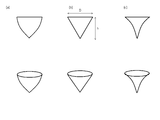
- the puncture cap 32 has been described as having a substantially conical shape, it may be not only a geometrical cone (FIG. 11b) but also a bullet shape (FIG. 11a) in which the conical oblique line bulges in a convex shape, or the conical oblique line is recessed in a concave shape.
- a horn shape (FIG. 11c) may be used.
- the substantially conical shape also includes a polygonal pyramid that approximates a circle.
- FIG. 12 is an explanatory diagram of the operation.
- the puncture cap 32 is in a closed state.
- the distal end (point) of the puncture cap 32 is brought into contact with a portion that becomes a hole in the abdominal wall. Then, force is applied to puncture the abdominal wall (S1).
- the subject of surgery (for example, an organ) is imaged by the camera 17.
- a real-time image is displayed on the monitor 7.
- the image is projected on the abdomen by the projector 8.
- the surgeon operates the forceps 4 while confirming the real-time image, and performs an operation (S4).
- the forceps 4 is removed. Furthermore, the trocar is gradually removed. At this time, the elasticity of the abdominal wall acts to close the hole. That is, a force acts on the slope of the puncture cap 32. By this action, the puncture cap 32 is gradually closed (S5). At this time, it has been confirmed by animal experiments that the abdominal wall is not sandwiched between the puncture cap 32 and the end face of the pipe portion 11.
- the trocar is removed so that the abdominal wall slides on the slope of the puncture cap 32.
- the hole in the abdominal wall closes naturally due to the elasticity of the abdominal wall (S6).
- the number of surgical procedures and the number of surgical instruments are reduced as compared with the prior art using an inner cylinder. As a result, the burden on the operator can be reduced.
- FIG. 13 shows another example of the puncture mechanism.
- the pipe end face 13 is formed in a shape obtained by obliquely cutting a cylinder, whereas the conventional pipe tip end face is flat (perpendicular to the axial direction).
- the pipe part end surface 13 becomes a slope shape, and a front-end
- the camera 17 is provided at the rear end of the slope.
- the tip (slope tip) 33 of the pipe end surface 13 functions as a puncture mechanism.
- the inner cylinder (described above) can be substituted.
- the camera 17 since the camera 17 is provided at the rear end of the slope, the camera does not become an obstacle during puncturing and insertion. In addition, it is possible to reduce the risk of organic substances (such as blood, meat, and body fluids) adhering to the camera.
- FIG. 14 is an example of the cleaning mechanism.
- the cleaning mechanism includes a shaft 41, a cleaning member 42, and a switching member 43 (not shown).
- the shaft 41 is fixed so as to be rotatable in the axial direction of the pipe portion 11 (embedded in the pipe wall), and one end portion is extended outside the trocar.
- a switching member 43 is connected to one end portion of the shaft 41.
- a cleaning member 42 is connected to the other end of the shaft 41. Resin, cloth, or the like is attached to the surface of the cleaning member 42 that contacts the camera. These have moderate flexibility and moderate rigidity so that they can resist sliding.
- the switching member 43 switches the cleaning member 42 between the normal position and the cleaning position.
- the cleaning member 42 In the normal position, the cleaning member 42 is arranged at a position corresponding to the shape of the pipe end face (see the drawing).
- the cleaning member 42 At the cleaning position, the cleaning member 42 is disposed at a position corresponding to the camera 17.
- Rotation of the switching member 43 causes the cleaning member 42 to contact the camera lens for cleaning via the shaft 41. After cleaning, the cleaning member 42 is returned from the cleaning position to the normal position. The rotation operation may be repeated several times. At this time, the state in which the forceps 4 are inserted into the trocar 1 can be maintained.
- the laparoscope In the conventional general laparoscopic lens cleaning operation, the laparoscope needs to be removed and inserted, and the operation is interrupted.
- the lens can be reliably cleaned by removing the fogging of the camera and organic matter only by the rotation of the switching member 43. Therefore, this embodiment can reduce the burden on the operator as compared with a conventional general laparoscopic lens cleaning operation.
- the trocar 1 is fixed by the contraction pressure of the abdominal wall, and the camera 17 is at the same position.
- offset before and behind lens cleaning can be prevented, and an operator's burden can be eased.
- by reducing the video shift it is possible to reduce the calculation processing load of the image processing device 6.
- This example has a simple configuration, is easy to manufacture, has almost no possibility of failure, and has high durability and safety.
- FIG. 15 is an example of a cleaning instrument.
- a cleaning mechanism is configured by combining with the trocar camera 1.
- the cleaning instrument has a shaft 46, a cleaning member 47, and a holding part 48.
- the shaft 46 is longer than the pipe shaft length.
- a cleaning member 47 is connected to one end of the shaft 46.
- a holding portion 48 is connected to the other end of the shaft 46.
- the cleaning member 47 is smaller than the inner diameter of the pipe and can be inserted through the pipe 11. Resin, cloth, or the like is attached to the surface of the cleaning member 47 that comes into contact with the camera. These have moderate flexibility and moderate rigidity so that they can resist sliding.
- the shaft 46 and the cleaning member 47 are inserted into the pipe 11, and the cleaning member 47 is disposed at a position corresponding to the camera 17.
- the cleaning member 47 comes into contact with the camera lens for cleaning via the shaft 41.
- the state in which the forceps 4 are inserted into the trocar 1 can be maintained. After cleaning, remove the cleaning implement.
- the second embodiment is a modification of the second embodiment, and the same effect can be obtained.
- the lymph node where the tumor first metastasizes is called the sentinel lymph node (SN).
- SN theory has been attracting attention, assuming that if there is no metastasis in the sentinel lymph node, there is no metastasis in the regional lymph node.
- technologies related to early detection of cancer are also progressing, and the excision range of tumors tends to be reduced. Based on these backgrounds, application of minimally invasive surgery such as laparoscopic surgery is being studied.
- ICG Indocyanine Green
- ICG is a low-toxic water-soluble compound that binds to plasma proteins and fluoresces.
- the excitation wavelength and fluorescence wavelength of ICG do not overlap with the absorption regions of water and hemoglobin, which are the main absorbents in the body. That is, it is a near-infrared wave and penetrates the body tissue. Therefore, it is possible to identify the vascular running position inside the tissue and the lesion site.
- FIG. 16 is a perspective view of a trocar camera for ICG fluorescence observation.
- FIG. 16A and FIG. 16B have different viewpoints.
- the trocar 1 includes a pipe part 11 and a head part 12.
- a near-infrared excitation light source 54 is provided on the end surface 13 of the pipe part 11.
- the near-infrared excitation light source 54 is a chip LED, for example, and irradiates excitation light having a wavelength of 800 nm.
- an infrared imaging device 57 is embedded in the tip wall surface of the pipe portion 11 so that the lens is positioned on the end surface 13 of the pipe portion 11.
- the infrared imaging device 57 detects ICG fluorescence having a wavelength of 840 nm, for example.
- the excitation wavelength and fluorescence wavelength are appropriately selected as appropriate.
- Other configurations are the same as those in FIG.
- FIG. 17 is a schematic configuration of the surgery support system 104.
- the surgery support system 104 includes a forceps trocar 1a having infrared imaging mechanisms 57a and 54a and a marker 19a, a forceps trocar 1b having infrared imaging mechanisms 57b and 54b and a marker 19b, a laparoscopic trocar 3 and forceps. 4a and 4b, a laparoscope 5 having a marker 19d, an image obtained from the infrared imaging devices 57a and 57b and an image obtained from the laparoscope 5, and an image processing device 6 that performs image processing on these images; A monitor 7 for outputting an image created by the image processing device 6 and an optical sensor 9 are provided. Other configurations are the same as those in FIG.
- a plurality of forceps for example, 3 to 5
- at least one ICG fluorescence observation trocar camera may be used, and a general trocar (without an infrared imaging mechanism) may be used for others.
- a trocar with a camera 17 may be used instead of the laparoscope 5 (see FIG. 7).
- the fluorescent dye ICG Prior to the ICG fluorescence observation, the fluorescent dye ICG is injected into the observation target in advance. Then, near infrared excitation light is emitted from the chip LED 54. The irradiated excitation light passes through the surface of the living body and is irradiated onto the observation target, and excites the fluorescent dye injected into the observation target to generate fluorescence. ICG fluorescence is detected by the infrared imaging device 57. In this way, an ICG fluorescence image is acquired.
- FIG. 18 is a conceptual diagram of image composition processing.
- Laparoscopic surgery using the surgery support system 101 is based on general laparoscopic surgery, and there is no major change in the surgical method. You can save it.
- the surgery support system 104 has a simple configuration using the trocar camera 1, and the existing surgery support system can be reused with a simple improvement.
- the trocar camera 1 is an improvement of a general trocar, has a simple structure, has a low risk of failure, and is low in production cost. In other words, this system is highly practical.
- the surgery support system 104 uses a trocar for inserting forceps, it is not necessary to make a new hole in the abdominal wall. Thereby, minimally invasiveness can be maintained.
- the trocar 1a has a marker 19a
- the laparoscope 5 has a marker 19d.
- the optical sensor 9 measures the three-dimensional positions of the markers 19a and 19d.
- the positional relationship between the marker 19a and the infrared imaging device 57a is unchanged. Therefore, the three-dimensional position of the infrared imaging device 57a can be accurately estimated based on the position of the marker 19a.
- the marker 19d is provided on the laparoscope 5, and the three-dimensional position of the laparoscope 5 camera can be accurately estimated based on the position of the marker 19d.
- the image processing apparatus 6 estimates the positions of the ICG fluorescence image and the visible light image. That is, the ICG fluorescence image and the visible light image are combined based on the positional relationship between the markers 19a and 19d.
- the ICG fluorescence image and the visible light image can be synthesized more accurately by estimating the depth direction information and the accurate plane direction information related to the ICG fluorescence image by the later-described ICG fluorescence three-dimensional observation.
- the ICG fluorescence image is an image inside the tissue, and information in the depth direction cannot be obtained.
- information in the depth direction is very useful.
- FIG. 19 shows a conceptual diagram related to scattering. That is, a deep and thin observation object (left figure) and a shallow and thick observation object (right figure) may be observed in the same manner. In other words, when information on the depth direction cannot be obtained, accurate information on the width direction (plane direction) cannot be obtained.
- the surgery support system 104 includes two infrared imaging mechanisms 57a, 57b, 54a, and 54b and corresponding markers 19a and 19b.
- the optical sensor 9 measures the three-dimensional positions of the markers 19a and 19b. Thereby, the three-dimensional position of the infrared imaging devices 57a and 57b can be accurately estimated based on the positions of the markers 19a and 19b.
- the image processing device 6 estimates the positions of the ICG fluorescence image by the infrared imaging device 57a and the ICG fluorescence image by the infrared imaging device 57b.
- FIG. 20 shows a conceptual diagram of three-dimensional observation. That is, information on the depth direction and the plane direction is estimated based on the positional relationship between the markers 19a and 19b. Further, the two ICG fluorescence images are synthesized and a three-dimensional image is output to the monitor 7. Note that accurate plane direction information may be output to the monitor 7 as an ICG fluorescence image (two-dimensional) and depth direction information as numerical values.
- infrared imaging mechanisms In the above description, two infrared imaging mechanisms have been described as examples. However, in general laparoscopic surgery, a plurality of (for example, about 3 to 5) forceps are used, so that three or more infrared imaging mechanisms are used. A mechanism may be used. For example, three virtual triangles (details will be described later) are formed by three infrared imaging mechanisms, and the estimation accuracy is improved.
- the trocar 1e has a pipe part 11, a head part 12, a camera 17e, and a marker 19e. That is, the infrared imaging device is replaced with a visible light camera (see FIG. 1).
- a visible light image can be obtained with the trocar 1e.
- a visible light image is obtained by the laparoscope 5.
- the positional relationship between the cameras can be estimated from the positional relationship between the markers 19d and 19e.
- the depth position of the target point can be estimated.
- the three-dimensional shape in the abdominal cavity can be measured by moving the target point and repeating the depth position estimation.
- the image processing device 6 estimates the three-dimensional information, combines the two visible light fluorescent images, and outputs the three-dimensional image to the monitor 7.
- accurate plane direction information may be output to the monitor 7 as a visible light image (two-dimensional) and depth direction information as a numerical value.
- the ICG fluorescence image has three-dimensional information
- the visible light image has three-dimensional information.
- the image processing device 6 synthesizes the ICG fluorescence image and the visible light image with high accuracy based on the three-dimensional information.
- ⁇ Port ⁇ The above description is based on the assumption of laparoscopic surgery, but the present invention may be applied to thoracoscopic surgery.
- a surgical instrument called a trocar in laparoscopic surgery is called a port in thoracoscopic surgery. That is, the trocar and the port are almost the same.
- the trocar camera (trocar with camera) can be variously modified.
- a light source 14 is provided on the end surface 13.
- FIG. 21 is a perspective view of this modification.
- a camera 17 is embedded in the end wall surface of the pipe portion 11 so that the lens is positioned on the end surface 13 of the pipe portion 11. On the other hand, there is no light source.
- ⁇ Trocar camera modification 2 ⁇ In the trocar camera shown in FIGS. 1 and 2, the light source 14 is provided on the end surface 13, whereas in the present modification, the light source 14 is on the end side of the pipe portion opposite to the end surface 13 (the side closer to the head portion 12). ).
- FIG. 22 is a partial cross-sectional view in the longitudinal direction of the present modification.
- FIG. 23 is a partial cross-sectional view in the lateral direction of the present modification.
- a stepped portion due to an enlarged diameter is provided between the pipe portion 11 and the head portion 12.
- a plurality of light sources are arranged in the circumferential direction at a position corresponding to the end surface of the pipe part 11 on the surface of the step part.
- the light source 14 When the light source 14 cannot be disposed on the surface of the stepped portion, it may be embedded on the end portion side of the pipe portion (side closer to the head portion 12).
- the pipe part 11 is made of a light transmissive material. Although it is preferably transparent, it may be translucent. Moreover, the refractive index is larger than that of air. On the other hand, like general trocars, characteristics such as moderate rigidity, heat resistance, and no influence on the human body are required. Specifically, polycarbonate or the like is applicable.
- the wiring cable 15 (not shown) of the light source 14 is shortened, so that the configuration is simplified. In addition, the risk of disconnection is reduced.
- the positional relationship with the camera 17 becomes important. On the other hand, such a study is unnecessary in the modified example. As a result, a large number of light sources 14 can be installed, and the amount of light can be secured.
- Modification 2 can be further modified.
- the trocar of the second modification is premised on having the camera 17, the camera 17 can be eliminated and used as an auxiliary light source.
- ⁇ Trocar camera modification 3 ⁇ Modification 3 is a modification of the trocar camera for ICG fluorescence observation shown in FIG.
- the near-infrared excitation light source 54 is provided on the end surface 13, whereas in the present modification, the near-infrared excitation light source 54 is on the end side of the pipe portion opposite to the end surface 13 (head Provided on the side close to the portion 12).
- the modification 3 can also be applied to ICG fluorescence observation, and the same effect as the modification 2 can be obtained.
- FIG. 1 and FIG. 2 there is one camera 17, whereas in the fourth modification, a plurality of cameras 17 are provided.
- FIG. 24 is a perspective view of this modification.
- Two cameras 17 are embedded so as to face each other in the circumferential direction on the end surface 13.
- the trocar camera according to the modification 4 can estimate the depth and measure the three-dimensional shape in the cavity.
Landscapes
- Health & Medical Sciences (AREA)
- Life Sciences & Earth Sciences (AREA)
- Surgery (AREA)
- Animal Behavior & Ethology (AREA)
- Public Health (AREA)
- Engineering & Computer Science (AREA)
- Biomedical Technology (AREA)
- Heart & Thoracic Surgery (AREA)
- Medical Informatics (AREA)
- Molecular Biology (AREA)
- Veterinary Medicine (AREA)
- General Health & Medical Sciences (AREA)
- Nuclear Medicine, Radiotherapy & Molecular Imaging (AREA)
- Pathology (AREA)
- Physics & Mathematics (AREA)
- Biophysics (AREA)
- Optics & Photonics (AREA)
- Radiology & Medical Imaging (AREA)
- Endoscopes (AREA)
- Surgical Instruments (AREA)
Abstract
腹腔鏡下手術において、低侵襲性を損なうことなく、視野の狭さを解消する。トロカール(1)は、医療器具を体内に挿入するためのパイプ部(11)と、パイプ部(11)の上部に連続して設けられるヘッド部(12)を有し、パイプ部(11)を介して腹壁に設けられる。パイプ部端面(13)に設けられるカメラ(17)および光源(14)が設けられている。カメラ(17)および光源(14)はケーブルを介して外部と接続している。鉗子用トロカールを用いるため、新たに腹壁に孔をあける必要はなく、低侵襲性を維持できる。トロカールカメラ(1)を用いることにより、腹腔内に複数のカメラ(17)を挿入することができる。これにより、視野を広げることができる。さらに、カメラ(17)は、鉗子(4)の先端部を確実に撮影するため、切断箇所など重要な画像を確実に得ることができる。
Description
本発明は、腹腔鏡下手術に用いるトロカールおよび関連技術に関する。ただし、胸腔鏡下手術に用いる場合はポートという。
近年、患者のQOL(quality of life)維持・向上のために腹腔鏡下手術などの低侵襲外科手術が求められている。腹腔鏡下手術は腹腔内に炭酸ガスを注入して腹壁を膨らませ、手技のための空間と視野を確保する。そして腹壁に小さい孔を設け、トロカールと呼ばれる器具を挿入する。そこから腹腔鏡(CCDカメラ)や外科器具である鉗子を患者の体内に挿入し、腹腔鏡によってモニタに表示される映像を観察しながら手術を行うのが一般的である(例えば特許文献1)。
ところで、この手術は腹腔鏡から得られる映像のみを頼りに行われるため視野が狭く、術者に負担がかかる。視野を拡大すべく別のカメラを挿入するように新たに腹壁に孔をあけると、低侵襲性を損なう。
本発明は上記課題を解決するものであり、腹腔鏡下手術において、低侵襲性を損なうことなく、視野の狭さを解消することを目的とする。
上記課題を解決する本発明は、医療器具を体内に挿入するためのパイプ部と、該パイプ部の上部に連続して設けられるヘッド部とを有し、該パイプ部を介して腹壁に設けられるトロカールであって、前記パイプ部端面に設けられるカメラを備える(トロカールカメラ)。
本発明において好ましくは、前記パイプ部端面に設けられる光源を更に備える。
本発明において好ましくは、前記パイプ部端面周方向において瘤部を有し、前記カメラは、該瘤部に設けられる。
本発明において好ましくは、前記パイプ部端面は、円筒を斜めに切断した形状に形成され、前記カメラは、該斜面後端に設けられる。
本発明において好ましくは、前記カメラは、ズーム機能を有する。
本発明において好ましくは、前記医療器具は鉗子である。
本発明において好ましくは、前記ヘッド部に設けられる位置マーカを更に備える。
本発明の手術支援システムは、上記のトロカールと、カメラと位置マーカとを有する腹腔鏡と、該腹腔鏡の位置マーカおよび該トロカールの位置マーカの位置を検出する位置検出センサと、該位置マーカの位置に基づき前記カメラの位置を推定し、該カメラの位置に基づき前記カメラから得られた画像を合成し、3次元画像を作成する画像処理装置とを備える。
本発明の手術支援システムは、複数の上記のトロカールと、前記位置マーカの位置を検出する位置センサと、該位置マーカの位置に基づき前記カメラの位置を推定し、該カメラの位置に基づき前記カメラから得られた画像を合成し、3次元画像を作成する画像処理装置と、を備える。
本発明の手術支援システムにおいて、好ましくは、手術台の上方に設けられ、前記3次元画像を患者の腹部に投影する3次元プロジェクタをさらに備える。
本発明において好ましくは、穿刺機構を更に備える。穿刺機構は、前記パイプ部先端に設けられたヒンジ機構と、前記ヒンジ機構を介してパイプ部端面開口を開閉可能に設けられ、先端が尖った穿刺キャップとを有する
本発明において好ましくは、前記穿刺キャップの外縁が前記パイプ部端面に当接されることで、パイプ部端面開口は閉じられ、該穿刺キャップの外縁は、該パイプ部端面の外円に含まれる。
本発明において好ましくは、前記穿刺キャップの外縁が前記パイプ部端面に当接されることで、パイプ部端面開口は閉じられ、該穿刺キャップの外縁は、該パイプ部端面の外円に含まれる。
本発明において好ましくは、クリーニング機構を更に備える。クリーニング機構は、前記パイプ部の軸方向に回動可能に固定され、かつ、一端部がトロカール外に延長されるシャフトと、該シャフトの他端部に連設されるクリーニング部材と、該シャフトの一端部に連設され、該クリーニング部材が前記パイプ部端面形状に対応する位置に配置される通常位置と、該クリーニング部材が前記カメラに対応する位置に配置されるクリーニング位置とに、該クリーニング部材を切り替える切替部材とを有する。該切替部材の回動により、該クリーニング部材がカメラレンズに接触してクリーニングする。
本発明は、上記トロカールカメラのレンズをクリーニングするカメラレンズクリーニング器具である。カメラレンズクリーニング器具は、トロカールのパイプ長より長いシャフトと、該シャフトの一端部に設けられる保持部と、該パイプ内径より小さく、前記カメラレンズに接触可能に該シャフトの一端部に設けられるクリーニング部材とを備える。
上記課題を解決する本発明は、医療器具を体内に挿入するためのパイプ部と、該パイプ部の上部に連続して設けられるヘッド部とを有し、該パイプ部を介して腹壁に設けられるトロカールであって、前記パイプ部端面に設けられる赤外撮像デバイスと、前記パイプ部端面に設けられ、近赤外励起光を照射する近赤外励起光源と
を備える。
を備える。
本発明の手術支援システムは、上記のトロカールを含み、ICG蛍光画像を取得するICG蛍光画像取得手段と、前記ICG蛍光画像に対応する可視光画像を取得する可視光画像取得手段とを備える。
上記課題を解決する本発明は、医療器具を体内に挿入するためのパイプ部と、該パイプ部の上部に連続して設けられるヘッド部とを有し、該パイプ部を介して胸壁に設けられるポートであって、前記パイプ部端面に設けられるカメラを備える。
本発明によれば、鉗子用トロカールを用いることで、新たに腹壁に孔をあけることなく、低侵襲性を損なうことがない。一方、腹腔鏡から得られる映像に加え、トロカールカメラから得られる映像を用いることにより、視野の狭さを解消できる。
≪カメラ付トロカール(トロカールカメラ)≫
~構成~
カメラ付トロカール(トロカールカメラ)の構成について説明する。図1は、トロカールカメラの斜視図である。図1(a)と図1(b)とは、視点が異なる。
~構成~
カメラ付トロカール(トロカールカメラ)の構成について説明する。図1は、トロカールカメラの斜視図である。図1(a)と図1(b)とは、視点が異なる。
トロカール1は、パイプ部11とヘッド部12から構成される。パイプ部11は、その大部分が腹壁の孔に挿入される。ヘッド部12はパイプ部11の上部に連続して設けられる。ヘッド部12は中空であり、その上部から鉗子が挿入可能になっている。また、詳細は省略するが、ヘッド部12は鉗子の挿抜時に空気の漏れを防止する密封機構と腹腔内に空気を送り込む送気機構とを備える。
パイプ部11の端面13にレンズが位置するように、パイプ部11先端壁面にカメラ17が埋設されている。カメラ17にはケーブル18が接続されており、ケーブル18はトロカール1内を挿通して、外部の画像処理装置6(後述)と接続している。
カメラの付加構成としてズーム機能を有している。ズーム機能は光学ズームでもデジタルズームでもよい。
パイプ部11の端面13には、さらに、光源14が設けられている。光源14は例えばチップLEDである。光源14にはケーブル15(図示省略)が接続されており、ケーブル15はケーブル18に並設され、外部電源と接続している。
~効果~
従来の一般的な腹腔鏡下手術では、腹腔鏡から得られる映像のみを頼りに行われるため視野が狭かった。視野を拡大すべく別のカメラを挿入するように新たに腹壁に孔をあけると、低侵襲性を損なう。
本実施形態では、鉗子用トロカールを用いるため、新たに腹壁に孔をあける必要はなく、低侵襲性を維持できる。
また、本実施形態では、トロカールカメラ1を用いることにより、腹腔内に複数のカメラ17を挿入することができる。これにより、視野を広げることができる。さらに、カメラ17は、鉗子4の先端部を確実に撮影するため、切断箇所など重要な画像を確実に得ることができる。
すなわち、低侵襲性を損なうことなく、視野の狭さを解消することができる。
~変形例~
図2は、トロカールカメラの変形例である。従来型のパイプ部は略真円であるのに対し、本実施形態は瘤部16を有する。
図2は、トロカールカメラの変形例である。従来型のパイプ部は略真円であるのに対し、本実施形態は瘤部16を有する。
カメラ17はパイプ部11先端壁面に埋設されており、小型カメラを想定している。しかしながら、カメラの小型化には限界がある。一方で、パイプ壁の厚さを厚くすることも限界がある。すなわち、カメラ埋設に充分なスペースを確保できない可能性もある。
本実施形態では、瘤部16によりカメラ埋設に充分なスペースを確保できる。一方、瘤部16がトロカール挿入の障害にならないことを実験により確認している。
さらに、光源14を瘤部16に設けても良い。
≪手術支援システム≫
(第1実施例)
~手術支援システム構成~
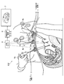
3次元画像を用いる手術支援システム101について説明する。図3は、手術支援システム101の概略構成である。
(第1実施例)
~手術支援システム構成~
3次元画像を用いる手術支援システム101について説明する。図3は、手術支援システム101の概略構成である。
手術支援システム101は、カメラ17aとマーカ19を有する鉗子用トロカール1aと、カメラ17bとマーカ19bを有する鉗子用トロカール1bと、腹腔鏡用トロカール3と、鉗子4a,4bと、マーカ19dを有する腹腔鏡5と、カメラ17a,17bから得られた画像と腹腔鏡5から得られた画像を入力し、これらの画像を合成処理し3次元画像を作成する画像処理装置6と、画像処理装置6により作成された3次元画像を出力する3次元モニタ7と、光学センサ9とを備えている。
鉗子4a,4bは、手術器具の一種であり、血管や臓器等を、掴んだり、抑えたり、引っ張ったり、切断したりするのに用いられる。一般的に鋏形状をしており、持手部の回動により、支点を介して先端部が作動する。持手部を閉状態にし、鉗子用トロカール1a,1bに挿通させる。なお、腹腔鏡下手術において、複数(例えば3~5)の鉗子を用いることが一般的であるが、本システムにおいて、鉗子および鉗子用トロカールは少なくとも1以上あればよい。
腹腔鏡5は、内視鏡器具の一種であり、カメラと光源を有している。腹腔鏡5は腹腔鏡用トロカール3を挿通して体内に挿入される。マーカ19dは、腹腔鏡5の体内に挿入されない位置に設けられている。
光学センサ9は、マーカ19a,19b,19dの3次元位置を計測し、計測結果を画像処理装置6に出力する。なお、本実施形態において、光学センサ9はマーカの白と黒を可視光線として認識するものであるが、赤外線を発信し、マーカで反射した赤外線を受信してもよい。光学センサに限定されず、3次元位置を計測できれば磁気センサでもよい。
~3次元形状計測~
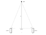
図4は、3次元形状計測の基本原理について説明する概念図である。2次元形状計測と3次元形状計測との一番の違いは、奥行きの推定である。
図4は、3次元形状計測の基本原理について説明する概念図である。2次元形状計測と3次元形状計測との一番の違いは、奥行きの推定である。
2つのカメラと対象ポイントとが形成する三角形において、2つのカメラ間の距離Lと、カメラ間基線と一のカメラ視線がなす角度αと、カメラ間基線と他のカメラ視線がなす角度βに基づいて、奥行きDを推定できる。なお、カメラ数を増やすことにより、より多くの三角形が形成されるため、推定精度が向上する。
本実施形態のトロカール1にはマーカ19が固定されている。一方、カメラ17はパイプ端面に設置されている。すなわち、マーカ19とカメラ17の位置関係は不変である。これにより、画像処理装置6はマーカ19a,19bの3次元位置に基づいてカメラ17a,17bの3次元位置を推定できる。同様に、マーカ19dの3次元位置に基づいて腹腔鏡5のカメラの3次元位置を推定できる。すなわち、カメラ間距離を推定できる。
さらに、対象ポイントごとに、角度α,βを測定し、上記基本原理に基づき、対象ポイントの奥行き位置を推定できる。対象ポイントを移動し、奥行き位置推定を繰り返すことにより、腹腔内の3次元形状を計測できる。
~システム全体の効果~
手術支援システム101を用いた腹腔鏡下手術は、一般的な腹腔鏡下手術を基礎とするものであり、手術方式の大きな変更がないため、術者はこれまでの手術に関する知識と経験をそのまま生かすことができる。
手術支援システム101を用いた腹腔鏡下手術は、一般的な腹腔鏡下手術を基礎とするものであり、手術方式の大きな変更がないため、術者はこれまでの手術に関する知識と経験をそのまま生かすことができる。
また、手術支援システム101は、改良したトロカールを用いた簡素な構成であり、既存の手術支援システムを簡単な改良で再利用することができる。
ところで、従来の一般的な腹腔鏡下手術では、腹腔鏡から得られる映像のみを頼りに行われるため視野が狭かった。特に、奥行きに係る画像情報が得られなかった。精度の良い3時次元形状計測をすべく別のカメラを挿入するように新たに腹壁に孔をあけると、低侵襲性を損なう。
本実施形態では、カメラ17a,17bを有するトロカール1a,1bを用いることにより、腹腔内に複数のカメラを挿入することができる。このとき、鉗子用トロカールを用いるため、新たに腹壁に孔をあける必要はない。これにより、低侵襲性を維持しながら、3次元形状を計測できる。
更に、画像処理装置6が3次元画像を作成し、3次元モニタ7に3次元画像を出力する。術者は3次元モニタ7を見ることで、奥行き情報を含む広い視野を得ることができる。これにより、術者の負担を軽減できる。
~精度向上に係る効果~
(1)3次元形状計測の基本原理について説明したように、奥行きを推定するには、カメラ17a,17bの3次元位置を推定する必要がある。しかしながら、カメラ17a,17bは腹腔内にあるため直接、位置を計測できない。さらに、鉗子4a,4bの動きに伴って、トロカール1a,1bの角度が変わり、その結果、カメラ17a,17bが微動する。そのため、3次元位置の推定は困難であるという課題がある。図5はカメラ位置推定の困難性に係る課題を説明する概念図である。
(1)3次元形状計測の基本原理について説明したように、奥行きを推定するには、カメラ17a,17bの3次元位置を推定する必要がある。しかしながら、カメラ17a,17bは腹腔内にあるため直接、位置を計測できない。さらに、鉗子4a,4bの動きに伴って、トロカール1a,1bの角度が変わり、その結果、カメラ17a,17bが微動する。そのため、3次元位置の推定は困難であるという課題がある。図5はカメラ位置推定の困難性に係る課題を説明する概念図である。
そこで、トロカール1a,1bの微動に連動してカメラ17a,17bが微動することに着目し、トロカール1a,1bのヘッド部12にマーカ19a,19bを設けた。すなわち、マーカ19a,19bとカメラ17a,17bの位置関係は不変である。一方、マーカ19a,19bの3次元位置は光学センサ9により精度よく検出できる。したがって、マーカ19a,19bの3次元位置に基づきカメラ17a,17bの3次元位置を精度よく推定できる。
なお、腹腔鏡5のカメラの動きは、トロカール3の微動と連動しないため、マーカ19dは腹腔鏡5に設けられている。これにより、腹腔鏡5のカメラの3次元位置を精度よく推定できる。
カメラの三次元位置を精度よく推定し、カメラ間距離を精度よく推定できる結果、奥行きを精度よく推定でき、腹腔内の3次元形状計測を精度よくおこなうことができる。
(2)3次元形状計測の基本原理について説明したように、カメラ数を増やすことにより、奥行き推定の精度が向上する。一般に、腹腔鏡下手術において、複数(例えば2~5程度)の鉗子が用いられる。その結果、腹腔鏡5以外にも、複数のカメラ17が腹腔内に挿入される。これにより、奥行きを精度よく推定でき、腹腔内の3次元形状計測を精度よくおこなうことができる。
(3)ところで、立体内視鏡を用いても、腹腔内の3次元形状計測は可能である。しかしながら、立体内視鏡は、カメラ間の距離が非常に狭く、三角形が極端に細長くなり、その結果、奥行き推定の精度が良くない。
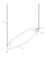
図6は、カメラ間距離と奥行き推定精度の関係を示す概念図である。図6(a)は、カメラ間距離が非常に狭いケース、図6(b)は、カメラ間距離が広いケースを示している。
図6(a)において、カメラ間距離を非常に狭いL1とし、実際の奥行きをDとする。カメラ視線に誤差があった場合の推定奥行きはD1となる。図6(b)において、カメラ間距離を充分広いL2とし、実際の奥行きをD(図6(a)と同じ)とする。カメラ視線に誤差(図6(a)と同レベル)があった場合の推定奥行きはD2となる。
推定奥行きD1は大きな誤差を有するのに対し、推定奥行きD2の誤差は小さい。
一般に、腹腔鏡下手術において、複数(例えば2~5程度)の鉗子用のトロカール1が腹壁にほぼ均等に配置される。言い換えると、トロカール1が密集して配置される可能性はほぼない。これにより、充分広いカメラ間距離を確保でき、奥行きを精度よく推定でき、腹腔内の3次元形状計測を精度よくおこなうことができる。
(第2実施例)
図7は手術支援システム102の概略構成図である。手術支援システム102は、カメラ17a,17b,17cとマーカ19a,19b,19cを有する鉗子用トロカール1a,1b,1cと、鉗子4a,4b,4cと、マーカ19a,19b,19cの3次元位置に基づきカメラ17a,17b,17cの3次元位置を推定し、カメラから得られた画像を合成し、3次元画像を作成する画像処理装置6と、画像処理装置6により作成された3次元画像を出力する3次元モニタ7とを備えている。
図7は手術支援システム102の概略構成図である。手術支援システム102は、カメラ17a,17b,17cとマーカ19a,19b,19cを有する鉗子用トロカール1a,1b,1cと、鉗子4a,4b,4cと、マーカ19a,19b,19cの3次元位置に基づきカメラ17a,17b,17cの3次元位置を推定し、カメラから得られた画像を合成し、3次元画像を作成する画像処理装置6と、画像処理装置6により作成された3次元画像を出力する3次元モニタ7とを備えている。
すなわち、実施例1の手術支援システム101における腹腔鏡用トロカール3と腹腔鏡5とマーカ19dとがなく、格納式カメラ17cを有する鉗子用トロカール1cと、鉗子4cとマーカ19cとが追加されている。
なお、腹腔鏡下手術において、複数の鉗子を用いることが一般的であるが、本システムにおいて、鉗子および鉗子用トロカールは少なくとも2以上あればよい。
実施例1の様に腹腔鏡5を用いる場合、術者が腹腔鏡5の向きを操作し切断箇所などを探す必要があるのに対し、カメラ17は、鉗子4aの先端部を確実に撮影するため、切断箇所など重要な画像を確実に得ることができる。したがって、カメラ17の性能が高いこと前提に、腹腔鏡5より高品質な画像を確実に得ることができる。
一方、腹腔鏡用トロカール3と腹腔鏡5が不要となることで、これらのための孔を腹壁にあける必要はなく、低侵襲性が向上する。
なお、本実施例では腹腔鏡を用いていないが、便宜上、腹腔鏡下手術と呼ぶ。
(第3実施例)
実施例3は実施例1・2の変形例である。実施例1・2では、術者はモニタ7を見ながら鉗子4や腹腔鏡5を操作し手術を行うが、術者の視線と実際の術野とに方向の不一致が生じ、術者に違和感を与え、負担になる。特に、開腹手術の経験豊富な術者は、腹腔鏡下手術に慣れないこともある。
実施例3は実施例1・2の変形例である。実施例1・2では、術者はモニタ7を見ながら鉗子4や腹腔鏡5を操作し手術を行うが、術者の視線と実際の術野とに方向の不一致が生じ、術者に違和感を与え、負担になる。特に、開腹手術の経験豊富な術者は、腹腔鏡下手術に慣れないこともある。
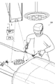
図8は手術支援システム103の概略構成図である。実施例1・2と共通する構成は適宜省略している。手術支援システム103は、3次元モニタ7に替えて、3次元プロジェクタ8を備えている。3次元プロジェクタ8は、手術台の上方に設けられ、画像処理装置6により作成された3次元画像を患者の腹部に直接投影する。
これにより、術者の視線と術野の方向は一致し、開腹手術と同様な現実感を表現できる。すなわち、術者の負担を軽減できる。
≪穿刺機構≫
本実施形態のトロカールカメラには、種々の穿刺機構が適用可能である。
本実施形態のトロカールカメラには、種々の穿刺機構が適用可能である。
(第1実施例)
本実施形態のトロカールカメラは、従来の穿刺機構に適用可能である。
本実施形態のトロカールカメラは、従来の穿刺機構に適用可能である。
従来技術では、トロカールを腹壁に挿入する際には、内筒を用いる。図9(a)はトロカール1と内筒111である。図9(b)はトロカール1と内筒111が一体化した図である。
内筒111は、基本構成として、シャフト部112と基部113とを有する。シャフト径は、トロカールのパイプ内径と同程度またはやや小さく、シャフト長は、トロカールのパイプ長よりやや長い。シャフト部先端114は槍の様に尖っている。内筒基部113は、トロカールヘッド部12と平面視にて同程度のサイズである。
内筒シャフト部112をトロカールパイプ部11に挿入し、内筒基部113をトロカールヘッド部12に係合させると、内筒111とトロカール1が一体化する。このとき、シャフト部先端114が突出している。
トロカール1を内筒111と一体として、腹壁に穿刺する。トロカールを所定の位置に固定したのち、内筒111を抜去する。そして、トロカール1を介して鉗子を挿入する。
(第2実施例)
次に、穿刺キャップについて説明する。図10は、穿刺キャップを有するトロカールの斜視図である。図10(a)と図10(b)とは、視点が異なる。
次に、穿刺キャップについて説明する。図10は、穿刺キャップを有するトロカールの斜視図である。図10(a)と図10(b)とは、視点が異なる。
穿刺機構は、ヒンジ機構31と穿刺キャップ32を有する。
ヒンジ機構31は、パイプ部11先端に、設けられている。ヒンジ機構31の配置がパイプ部11端面開口と干渉しないようにすることにより、鉗子挿入の障害とならないようにする。
穿刺キャップ32は略円錐状であり、中実でもよいし、剛性が確保できれば、中空でもよい。略円錐状であるため、先端が尖っている。穿刺キャップ32は、ヒンジ機構31を介してパイプ部11端面開口を開閉可能に設けられている。
すなわち、穿刺キャップ32の外縁(略円錐底面の外周線)がパイプ部11端面に当接されることで、パイプ部11端面開口は閉じられる。この当接状態が解除されることで、パイプ部11端面開口は開かれる。
好ましくは、平面視にて、穿刺キャップ32の外縁がパイプ部11端面の外円に含まれる。更に好ましくは、穿刺キャップ32の外縁がパイプ部11端面の外円に一致する。これにより、トロカール抜去の際に、腹壁に引っかかることがない。
円錐高hは円錐底面直径Dの0.5~2.0倍であることが好ましい。円錐高hが高すぎると(2.0倍超)、トロカール挿入後に、腹腔内で穿刺キャップ32が障害となるおそれがある。円錐高hが低すぎると(0.5倍未満)、穿刺が難しくなるおそれがある。当該範囲にすることにより、確実に穿刺できるとともに、腹腔内で穿刺キャップが障害となることを防止できる。
図11はキャップ形状の変形例の側面図及び斜視図である。穿刺キャップ32を略円錐状と説明したが、幾何学的な円錐(図11b)だけでなく、円錐斜線が凸状に膨らんだ弾丸形状(図11a)でもよいし、円錐斜線が凹状にへこんだホーン形状(図11c)でもよい。また、略円錐状とは、円に近似した多角錐をも含む。
穿刺キャップの動作について説明する。図12は、動作説明図である。
穿刺キャップ32は閉状態にある。穿刺キャップ32先端(尖部)を腹壁の孔となる箇所に当接する。そして、力を加えて、腹壁に穿刺する(S1)。
更に力を加えて、トロカールを所定の位置まで挿入する。トロカールは腹壁の弾力(収縮圧)により固定される(S2)。
パイプ部11に鉗子4を挿入する。このとき、鉗子先端が穿刺キャップ32の裏側に接触することで、穿刺キャップ32が開状態になる(S3)。
カメラ17により手術対象(例えば臓器)を撮影する。これにより、リアルタイム画像がモニタ7に表示される。または、プロジェクタ8により腹部に投影される。術者は、リアルタイム画像を確認しながら、鉗子4を操作し、手術を行う(S4)。
術後、鉗子4を抜去する。さらに、トロカールを徐々に抜去する。このとき、腹壁の弾力は、孔を閉じるように作用する。すなわち、穿刺キャップ32斜面に力が作用する。この作用により、穿刺キャップ32は徐々に閉じ状態になる(S5)。なお、このとき、穿刺キャップ32とパイプ部11端面との間に腹壁が挟まれないことを、動物実験により確認している。
腹壁が穿刺キャップ32斜面を滑るように、トロカールは抜去される。トロカールが完全に抜去されると、腹壁の孔は、腹壁の弾力により自然と閉じる(S6)。
本実施例では、内筒を用いる従来技術にくらべて、手術手順数および手術器具数が軽減されている。その結果、術者の負担を軽減できる。
(第3実施例)
図13は、穿刺機構の別の例である。従来型のパイプ部先端面はフラット(軸方向に垂直)であるのに対し、本実施例では、パイプ部端面13は、円筒を斜めに切断した形状に形成される。これにより、パイプ部端面13は斜面状となり、先端と後端が形成される。カメラ17は、斜面後端に設けられる。
図13は、穿刺機構の別の例である。従来型のパイプ部先端面はフラット(軸方向に垂直)であるのに対し、本実施例では、パイプ部端面13は、円筒を斜めに切断した形状に形成される。これにより、パイプ部端面13は斜面状となり、先端と後端が形成される。カメラ17は、斜面後端に設けられる。
パイプ部端面13の先端(斜面先端)33は穿刺機構として機能する。これにより内筒(上述)に代替できる。一方、カメラ17が斜面後端に設けられることにより、穿刺および挿入の際に、カメラが障害となることがない。また、カメラに有機物(例えば血や肉や体液)が付着するおそれを軽減できる。
≪クリーニング機構≫
一般的な、腹腔鏡下手術の最中に、腹腔鏡のレンズが曇ったり、有機物(油膜や組織片、更に具体的には血や肉や体液)が付着したりし、視野を確保できなくなることがある。したがって、その都度、腹腔鏡をトロカールから抜去してレンズを拭いた後、再びトロカールに挿入する。その結果、レンズクリーニングの度に手術の進行が一時的に中断してしまう。レンズクリーニングに係る動作は一回の手術で10回以上繰り返される。これらの動作は、本来の手術手順には必要ない一方、術者の負担になっている。
一般的な、腹腔鏡下手術の最中に、腹腔鏡のレンズが曇ったり、有機物(油膜や組織片、更に具体的には血や肉や体液)が付着したりし、視野を確保できなくなることがある。したがって、その都度、腹腔鏡をトロカールから抜去してレンズを拭いた後、再びトロカールに挿入する。その結果、レンズクリーニングの度に手術の進行が一時的に中断してしまう。レンズクリーニングに係る動作は一回の手術で10回以上繰り返される。これらの動作は、本来の手術手順には必要ない一方、術者の負担になっている。
したがって、新技術において新たなクリーニング機構を検討する必要がある。本実施形態のトロカールカメラには、種々のクリーニング機構が適用可能である。
(第1実施例)
図14は、クリーニング機構の一例である。クリーニング機構は、シャフト41と、クリーニング部材42と、切替部材43(図示省略)を有する。
図14は、クリーニング機構の一例である。クリーニング機構は、シャフト41と、クリーニング部材42と、切替部材43(図示省略)を有する。
シャフト41は、パイプ部11の軸方向に回動可能に固定され(パイプ壁に埋設され)、かつ、一端部がトロカール外に延長されている。シャフト41の一端部には、切替部材43が連設されている。
シャフト41の他端部には、クリーニング部材42が連設されている。クリーニング部材42のカメラに接触する側の面には、樹脂や布等が貼られている。これらは、適度な柔軟性を有し、かつ、摺動に対抗できるように適度な剛性を有する。
切替部材43は、クリーニング部材42を通常位置とクリーニング位置とに、該クリーニング部材を切り替える。通常位置では、クリーニング部材42はパイプ部端面形状に対応する位置に配置される(図示参照)。クリーニング位置では、クリーニング部材42がカメラ17に対応する位置に配置される。
切替部材43の回動により、シャフト41を介して、クリーニング部材42がカメラレンズに接触してクリーニングする。クリーニング後は、クリーニング位置から通常位置にクリーニング部材42を戻す。回動動作を数回繰り返しても良い。このとき、トロカール1に鉗子4が挿入された状態を維持できる。
第1実施例の効果について説明する。
従来の一般的な腹腔鏡のレンズクリーニング動作では、腹腔鏡の抜去および挿入が必要であり、手術が中断する。これに対し、本実施例では、切替部材43による回動のみで、カメラの曇りや有機物を除去し、レンズを確実にクリーニングすることができる。したがって、本実施例は、従来の一般的な腹腔鏡のレンズクリーニング動作に比べ、術者の負担を軽減することができる。
また、 従来の一般的な腹腔鏡のレンズクリーニング動作では、レンズクリーニングの前後において、映像ズレが発生するおそれがある。これに対し、本実施例では、腹壁の収縮圧によりトロカール1は固定されており、カメラ17は同じ位置にある。これにより、レンズクリーニング前後の映像ズレを防止し、術者の負担を軽減することができる。更に、映像ズレを軽減することで、画像処理装置6の演算処理負担を軽減できる。
本実施例は、簡素な構成であり、製作が容易であり、故障の可能性がほぼ無く、耐久性、安全性が高い。
(第2実施例)
図15は、クリーニング器具の一例である。トロカールカメラ1と組み合わせることによりクリーニング機構を構成する。クリーニング器具は、シャフト46と、クリーニング部材47と、保持部48とを有する。
図15は、クリーニング器具の一例である。トロカールカメラ1と組み合わせることによりクリーニング機構を構成する。クリーニング器具は、シャフト46と、クリーニング部材47と、保持部48とを有する。
シャフト46は、パイプ軸長より長い。シャフト46の一端にはクリーニング部材47が連設されている。シャフト46の他端には保持部48が連設されている。
クリーニング部材47はパイプ内径より小さく、パイプ11内を挿通可能である。クリーニング部材47のカメラに接触する側の面には、樹脂や布等が貼られている。これらは、適度な柔軟性を有し、かつ、摺動に対抗できるように適度な剛性を有する。
保持部48を操作するとことで、シャフト46およびクリーニング部材47はパイプ11内に挿入され、クリーニング部材47がカメラ17に対応する位置に配置される。保持部48を微動することにより、シャフト41を介して、クリーニング部材47がカメラレンズに接触してクリーニングする。このとき、トロカール1に鉗子4が挿入された状態を維持できる。クリーニング後は、クリーニング器具を抜去する。
第2実施例は第2実施例の変形例であり、同様な効果が得られる。
≪ICG蛍光観察≫
~概要~
腫瘍が最初に転移をおこすリンパ節をセンチネルリンパ節(SN)と呼ぶ。近年、センチネルリンパ節に転移が存在しなければ、領域リンパ節には転移はないと仮定するSN理論が注目されている。また、癌の早期発見に係る技術も進歩しており、腫瘍の切除範囲は縮小する傾向にある。これらの背景により、腹腔鏡下手術などの低侵襲外科手術の適用が検討されている。
~概要~
腫瘍が最初に転移をおこすリンパ節をセンチネルリンパ節(SN)と呼ぶ。近年、センチネルリンパ節に転移が存在しなければ、領域リンパ節には転移はないと仮定するSN理論が注目されている。また、癌の早期発見に係る技術も進歩しており、腫瘍の切除範囲は縮小する傾向にある。これらの背景により、腹腔鏡下手術などの低侵襲外科手術の適用が検討されている。
一方、ICG蛍光観察に係る技術も注目されている。ICG(インドシニアングリーン)は低毒性の水溶性化合物であり、血漿蛋白と結合して蛍光するという性質を有する。また、ICGの励起波長および蛍光波長は体内における主な吸物質である水やヘモグロビンの吸光領域と重ならない。すなわち、近赤外波であり、体内組織を透過する。従って、組織内部の血管走行位同定や、病変部位の同定が可能である。
通常、腹腔鏡下手術を行う術者は術前に切除範囲を確認する。一方で、手術中も切除範囲を確認したいという要望が多かった。また、重大な医療事故につながる血管の誤切断を防ぐためにも、切除対象まわりの血管を確認したいという要望があった。
これに対し、本実施形態は、胸腔鏡下手術において、可視光観察とICG蛍光観察との同時観察を簡便に行う。
~システム基本構成~
図16は、ICG蛍光観察用のトロカールカメラの斜視図である。図16(a)と図16(b)とは、視点が異なる。
図16は、ICG蛍光観察用のトロカールカメラの斜視図である。図16(a)と図16(b)とは、視点が異なる。
トロカール1は、パイプ部11とヘッド部12から構成される。パイプ部11の端面13には、近赤外励起光源54が設けられている。近赤外励起光源54は、例えばチップLEDであり、波長800nmの励起光を照射する。さらに、パイプ部11の端面13にレンズが位置するように、パイプ部11先端壁面に赤外撮像デバイス57が埋設されている。赤外撮像デバイス57は、例えば波長840nmのICG蛍光を検出する。なお、励起波長、蛍光波長は、適宜、最適なものを選択する。その他の構成は、図1と共通である。
図17は、手術支援システム104の概略構成である。手術支援システム104は、赤外撮像機構57a,54aとマーカ19aを有する鉗子用トロカール1aと、赤外撮像機構57b,54bとマーカ19bを有する鉗子用トロカール1bと、腹腔鏡用トロカール3と、鉗子4a,4bと、マーカ19dを有する腹腔鏡5と、赤外撮像デバイス57a,57bから得られた画像と腹腔鏡5から得られた画像を入力し、これらを画像処理する画像処理装置6と、画像処理装置6により作成された画像を出力するモニタ7と、光学センサ9とを備えている。その他の構成は、図3と共通である。
なお、腹腔鏡下手術において、複数(例えば3~5)の鉗子を用いることが一般的である。本システムにおいて、少なくとも1以上のICG蛍光観察用のトロカールカメラを用いればよく、その他は一般的なトロカール(赤外撮像機構なし)を用いてもよい。
また、腹腔鏡5に代えて、カメラ17付トロカールを用いても良い(図7参照)。
~基本動作~
腹腔鏡5により可視光観察を行い、可視光画像を取得する。
腹腔鏡5により可視光観察を行い、可視光画像を取得する。
ICG蛍光観察に先立ち、予め観察対象に蛍光色素ICGを注入する。そして、チップLED54により近赤外励起光を照射する。照射された励起光は生体表面を透過して観察対象に照射され、観察対象に注入された蛍光色素を励起し、蛍光を発生させる。赤外撮像デバイス57によりICG蛍光を検出する。このように、ICG蛍光画像を取得する。
ICG蛍光画像と可視光画像を合成処理し(詳細後述)、重畳表示する。図18は、画像合成処理の概念図である。
~効果~
手術支援システム104を用いることにより、胸腔鏡下手術において、可視光観察とICG蛍光観察との同時観察を簡便に行うことができる。
手術支援システム104を用いることにより、胸腔鏡下手術において、可視光観察とICG蛍光観察との同時観察を簡便に行うことができる。
これにより、術者は、術中に切除範囲や切除対象周りの血管を確認できる。その結果、術者の負担を軽減し、手術の安全性を高めることができる。
手術支援システム101を用いた腹腔鏡下手術は、一般的な腹腔鏡下手術を基礎とするものであり、手術方式の大きな変更がないため、術者はこれまでの手術に関する知識と経験をそのまま生かすことができる。
また、手術支援システム104は、トロカールカメラ1を用いた簡素な構成であり、既存の手術支援システムを簡単な改良で再利用することができる。
トロカールカメラ1は、一般的なトロカールを改良したものであり、構成が簡単であり、故障のおそれが少なく、製作コストも低い。言い換えると、本システムは実用性が高い。
また、手術支援システム104では、鉗子挿入のためのトロカールを利用しているため、新たに腹壁に孔をあける必要はない。これにより、低侵襲性を維持できる。
なお、上記に手術支援システムの基本構成と基本動作について説明したが、更に、下記の構成を有していてもよい。
~画像合成~
一般に、2つの画像を合成する場合、各画像上に共通の基準点を設定し、基準点に基づいて、画像を合成する。しかし、可視光画像は組織表面の画像であるのに対し、ICG蛍光画像は、組織内部の画像であり、画像上に共通の基準点を設定することが難しい。とくに、本実施形態では、別々の撮像手段5,57により取得するため、位置合わせが難しい。
一般に、2つの画像を合成する場合、各画像上に共通の基準点を設定し、基準点に基づいて、画像を合成する。しかし、可視光画像は組織表面の画像であるのに対し、ICG蛍光画像は、組織内部の画像であり、画像上に共通の基準点を設定することが難しい。とくに、本実施形態では、別々の撮像手段5,57により取得するため、位置合わせが難しい。
本実施形態においては、トロカール1aはマーカ19aを有し、腹腔鏡5はマーカ19dを有する。光学センサ9は、マーカ19a,19dの3次元位置を計測する。
マーカ19aと赤外撮像デバイス57aの位置関係は不変である。したがって、マーカ19a位置に基づき赤外撮像デバイス57aの3次元位置を精度よく推定できる。マーカ19dは腹腔鏡5に設けられており、マーカ19d位置に基づき腹腔鏡5のカメラの3次元位置を精度よく推定できる。
これにより、画像処理装置6は、ICG蛍光画像および可視光画像の位置を推定する。すなわち、マーカ19a,19d間の位置関係に基づいて、ICG蛍光画像と可視光画像とを合成処理する。
さらに、後述するICG蛍光3次元観察により、ICG蛍光画像に係る深さ方向の情報および正確な平面方向の情報を推定することで、より精度よくICG蛍光画像と可視光画像とを合成処理できる。
~ICG蛍光3次元観察~
ICG蛍光画像は、組織内部の画像であり、深さ方向の情報は得られない。一方、ICG蛍光画像により切除範囲を確認する場合や、周囲の血管を確認する場合、深さ方向の情報は非常に有用である。
ICG蛍光画像は、組織内部の画像であり、深さ方向の情報は得られない。一方、ICG蛍光画像により切除範囲を確認する場合や、周囲の血管を確認する場合、深さ方向の情報は非常に有用である。
また、ICG蛍光は組織を透過して組織表面に表れる。従って、観察対象が深くなるほど大きく見える。その結果、ICG蛍光画像には散乱性に係る課題がある。図19に散乱性に係る概念図を示す。すなわち、深く細い観察対象(左図)と、浅く太い観察対象(右図)が、同様に観察される可能性がある。言い換えると、深さ方向の情報が得られない場合、正確な幅方向(平面方向)の情報が得られない。
従って、既存のICG蛍光画像は、位置情報の精度に欠けるという課題があった。
本実施形態において、手術支援システム104は、2つの赤外撮像機構57a,57b,54a,54bと対応するマーカ19a,19bを有する。光学センサ9は、マーカ19a,19bの3次元位置を計測する。これにより、マーカ19a,19b位置に基づき赤外撮像デバイス57a,57bの3次元位置を精度よく推定できる。画像処理装置6は、赤外撮像デバイス57aによるICG蛍光画像および赤外撮像デバイス57bによるICG蛍光画像の位置を推定する。
図20に、3次元観察の概念図を示す。すなわち、マーカ19a,19b間の位置関係に基づいて、深さ方向および平面方向の情報を推定する。さらに、2つのICG蛍光画像を合成処理し、モニタ7に3次元画像を出力する。なお、正確な平面方向の情報をICG蛍光画像(2次元)として、深さ方向の情報を数値として、モニタ7に出力してもよい。
これにより、ICG蛍光画像に係る深さ方向の情報および正確な平面方向の情報が得られる。
また、上記では、2つの赤外撮像機構を例にして説明したが、一般的な腹腔鏡下手術において、複数(例えば3~5程度)の鉗子が用いられるため、3つ以上の赤外撮像機構を用いてもよい。たとえば、3つの赤外撮像機構により、3つの仮想三角形(詳細後述)が形成され、推定精度が向上する。
ところで、一般的な腹腔鏡下手術において、複数の鉗子用のトロカール1が腹壁にほぼ均等に配置される。言い換えると、トロカール1が密集して配置される可能性はほぼない。これにより、充分広い観測点間距離を確保でき、推定精度が向上する。
~可視光3次元観察~
上記に、ICG蛍光の3次元観察について説明したが、当然、可視光についても3次元観察が可能である。
上記に、ICG蛍光の3次元観察について説明したが、当然、可視光についても3次元観察が可能である。
図17に示す、手術支援システム101の概略構成図においては、見やすさの観点から、2つの鉗子用トロカール1a,1bしか記載していない。一方で、一般的な腹腔鏡下手術において、複数(例えば3~5程度)の鉗子が用いられる。ここでは、図示されていない鉗子用トロカール1eを用いる。
トロカール1eは、パイプ部11と、ヘッド部12と、カメラ17eと、マーカ19eを有する。即ち、赤外撮像デバイスを可視光カメラに置き換えたものである(図1参照)。
トロカール1eにより可視光画像が得られる。一方、腹腔鏡5により可視光画像が得られる。また、マーカ19d,19eの位置関係より、カメラ間の位置関係を推定できる。図4に示す、3次元観察の基本原理に基づき、対象ポイントの奥行き位置を推定できる。対象ポイントを移動し、奥行き位置推定を繰り返すことにより、腹腔内の3次元形状を計測できる。
これにより、画像処理装置6は、3次元情報を推定し、2つの可視光蛍光画像を合成処理し、モニタ7に3次元画像を出力する。なお、正確な平面方向の情報を可視光画像(2次元)として、深さ方向の情報を数値として、モニタ7に出力してもよい。
さらに、上記ICG蛍光画像は3次元情報が得られており、可視光画像も3次元情報が得られる。画像処理装置6は、3次元情報に基づいてICG蛍光画像と可視光画像とを精度よく合成処理する。
≪ポート≫
以上、腹腔鏡下手術を前提に説明したが、本発明は、胸腔鏡下手術に適用しても良い。ただし、腹腔鏡下手術においてトロカールと呼ばれる手術器具は、胸腔鏡下手術においてポートと呼ばれる。すなわち、トロカールとポートはほぼ同じものである。
以上、腹腔鏡下手術を前提に説明したが、本発明は、胸腔鏡下手術に適用しても良い。ただし、腹腔鏡下手術においてトロカールと呼ばれる手術器具は、胸腔鏡下手術においてポートと呼ばれる。すなわち、トロカールとポートはほぼ同じものである。
≪トロカールカメラ変形例1≫
トロカールカメラ(カメラ付トロカール)は種々の変形が可能である。図1や図2に示すトロカールカメラでは、端面13に光源14が設けられている。ところで、腹腔鏡5を併用し、腹腔鏡5の光源により充分な光量を確保できる場合は、トロカールカメラの光源は不要になる。
トロカールカメラ(カメラ付トロカール)は種々の変形が可能である。図1や図2に示すトロカールカメラでは、端面13に光源14が設けられている。ところで、腹腔鏡5を併用し、腹腔鏡5の光源により充分な光量を確保できる場合は、トロカールカメラの光源は不要になる。
図21は、本変形例の斜視図である。パイプ部11の端面13にレンズが位置するように、パイプ部11先端壁面にカメラ17が埋設されている。一方で、光源はない。
≪トロカールカメラ変形例2≫
図1や図2に示すトロカールカメラでは、端面13に光源14が設けられているのに対し、本変形例では光源14は端面13と反対側のパイプ部端部側(ヘッド部12に近い側)に設けられる。
図1や図2に示すトロカールカメラでは、端面13に光源14が設けられているのに対し、本変形例では光源14は端面13と反対側のパイプ部端部側(ヘッド部12に近い側)に設けられる。
図22は、本変形例の長手方向の部分断面図である。図23は、本変形例の短手方向の部分断面図である。
一般的なトロカールでは、パイプ部11とヘッド部12との間に拡径による段差部が設けられている。段差部表面であって、パイプ部11端面相当位置に、複数の光源を周方向に配置する。
光源14が、段差部表面に配置不可な場合は、パイプ部端部側(ヘッド部12に近い側)に埋設されていてもよい。
パイプ部11は光透過性を有する材料により構成されている。透明であることが好ましいが、半透明であってもよい。また、空気より屈折率が大きい。一方で、一般的なトロカールと同様に適度な剛性や耐熱性、人体への影響がないことなどの特性も必要である。具体的にはポリカーボネートなどが適用可能である。
光源14から所定角度で光が照射されると、パイプ部11内で全反射されながら伝達され、端面13より出射される。このとき、全反射により、光がパイプ部側面から漏れることがなく、ほぼ損失なく伝達される。
図1に示すトロカールカメラと本変形例との相違点による効果について説明する。
本変形例では、光源14の配線ケーブル15(図示省略)が短くなるため、構成が簡素化される。また断線のおそれも低減する。
端面13に光源14を設ける場合、カメラ17との位置関係が重要になる。これに対し、変形例ではこのような検討は不要である。その結果、多数の光源14を設置することができ、光量を確保できる。
変形例2を更に変形することもできる。変形例2のトロカールはカメラ17を有することを前提とするが、カメラ17を無くし、補助光源として利用することもできる。
≪トロカールカメラ変形例3≫
変形例3は、図16に示すICG蛍光観察用トロカールカメラの変形例である。図16に示すトロカールカメラでは、端面13に近赤外励起光源54が設けられているのに対し、本変形例では近赤外励起光源54は端面13と反対側のパイプ部端部側(ヘッド部12に近い側)に設けられる。
変形例3は、図16に示すICG蛍光観察用トロカールカメラの変形例である。図16に示すトロカールカメラでは、端面13に近赤外励起光源54が設けられているのに対し、本変形例では近赤外励起光源54は端面13と反対側のパイプ部端部側(ヘッド部12に近い側)に設けられる。
近赤外励起光源54の配置については、変形例2(図22および図23参照)に類似するため、図示を省略する。変形例3においても、ICG蛍光観察に適用できるとともに、変形例2と同様な効果が得られる。
≪トロカールカメラ変形例4≫
図1や図2においては、カメラ17は一つであるのに対し、変形例4においては、カメラ17は複数設けられている。
図1や図2においては、カメラ17は一つであるのに対し、変形例4においては、カメラ17は複数設けられている。
図24は、本変形例の斜視図である。端面13において周方向に相対向するように、2つのカメラ17が埋設されている。
ところで、図6に示す概念図を用いて、複数のトロカールカメラを用いることによる効果(奥行き推定精度向上)について説明した。一方で、おおまかな精度で良い場合は、変形例4に係るトロカールカメラ単体でも、奥行きを推定し、腔内の3次元形状計測をおこなうことができる。
もちろん、複数のトロカールカメラを併用することで、精度は向上する。
1 トロカール(トロカールカメラ)
3 腹腔鏡用トロカール
4 鉗子
5 腹腔鏡
6 画像処理装置
7 モニタ
8 プロジェクタ
9 光学センサ
11 パイプ部
12 ヘッド部
13 パイプ端面
14 光源
15 ケーブル
16 瘤部
17 カメラ
18 ケーブル
19 マーカ
31 ヒンジ機構
32 穿刺キャップ
33 斜面先端
41 シャフト
42 クリーニング部材
43 切替部材
46 シャフト
47 クリーニング部材
48 保持部
54 近赤外励起光源
57 赤外撮像デバイス
101~104 手術支援システム
111 内筒
112 シャフト部
113 基部
114 シャフト部先端
3 腹腔鏡用トロカール
4 鉗子
5 腹腔鏡
6 画像処理装置
7 モニタ
8 プロジェクタ
9 光学センサ
11 パイプ部
12 ヘッド部
13 パイプ端面
14 光源
15 ケーブル
16 瘤部
17 カメラ
18 ケーブル
19 マーカ
31 ヒンジ機構
32 穿刺キャップ
33 斜面先端
41 シャフト
42 クリーニング部材
43 切替部材
46 シャフト
47 クリーニング部材
48 保持部
54 近赤外励起光源
57 赤外撮像デバイス
101~104 手術支援システム
111 内筒
112 シャフト部
113 基部
114 シャフト部先端
Claims (19)
- 医療器具を体内に挿入するためのパイプ部と、該パイプ部の上部に連続して設けられるヘッド部とを有し、該パイプ部を介して腹壁に設けられるトロカールであって、
前記パイプ部端面に設けられるカメラを備えることを特徴とするトロカール。 - 前記パイプ部端面に設けられる光源を更に備えることを特徴とする請求項1記載のトロカール。
- 前記パイプ部端面周方向において瘤部を有し、
前記カメラは、該瘤部に設けられる
ことを特徴とする請求項1または2記載のトロカール。 - 前記パイプ部端面は、円筒を斜めに切断した形状に形成され、
前記カメラは、該斜面後端に設けられる
ことを特徴とする請求項1~3いずれか記載のトロカール。 - 前記カメラは、ズーム機能を有する
ことを特徴とする請求項1いずれか記載のトロカール。 - 前記ヘッド部に設けられる位置マーカを更に備えることを特徴とする請求項1記載のトロカール。
- 請求項6記載のトロカールと、
カメラと位置マーカとを有する腹腔鏡と、
該腹腔鏡の位置マーカおよび該トロカールの位置マーカの位置を検出する位置検出センサと、
該位置マーカの位置に基づき前記カメラの位置を推定し、該カメラの位置に基づき前記カメラから得られた画像を合成し、3次元画像を作成する画像処理装置と
を備えることを特徴とする手術支援システム。 - 複数の請求項6記載のトロカールと、
前記位置マーカの位置を検出する位置センサと、
該位置マーカの位置に基づき前記カメラの位置を推定し、該カメラの位置に基づき前記カメラから得られた画像を合成し、3次元画像を作成する画像処理装置と、
を備えることを特徴とする手術支援システム。 - 手術台の上方に設けられ、前記3次元画像を患者の腹部に投影する3次元プロジェクタ
をさらに備えることを特徴とする請求項7および8記載の手術支援システム。 - 前記パイプ部先端に設けられたヒンジ機構と、
前記ヒンジ機構を介してパイプ部端面開口を開閉可能に設けられ、先端が尖った穿刺キャップと
を有する穿刺機構
を更に備えることを特徴とする請求項1記載のトロカール。 - 前記パイプ部の軸方向に回動可能に固定され、かつ、一端部がトロカール外に延長されるシャフトと、
該シャフトの他端部に連設されるクリーニング部材と、
該シャフトの一端部に連設され、該クリーニング部材が前記パイプ部端面形状に対応する位置に配置される通常位置と、該クリーニング部材が前記カメラに対応する位置に配置されるクリーニング位置とに、該クリーニング部材を切り替える切替部材と
を有し、
該切替部材の回動により、該クリーニング部材がカメラレンズに接触してクリーニングする
クリーニング機構
を更に備えることを特徴とする請求項1記載のトロカール。 - 請求項1記載のトロカールのパイプ長より長いシャフトと、
該シャフトの一端部に設けられる保持部と、
該パイプ内径より小さく、前記カメラレンズに接触可能に該シャフトの一端部に設けられるクリーニング部材と
を備えることを特徴とするカメラレンズクリーニング器具。 - 医療器具を体内に挿入するためのパイプ部と、該パイプ部の上部に連続して設けられるヘッド部とを有し、該パイプ部を介して腹壁に設けられるトロカールであって、
前記パイプ部端面に設けられる赤外撮像デバイスと、
前記パイプ部端面に設けられ、近赤外励起光を照射する近赤外励起光源と
を備えることを特徴とするトロカール。 - 請求項13記載のトロカールを含み、ICG蛍光画像を取得するICG蛍光画像取得手段と、
前記ICG蛍光画像に対応する可視光画像を取得する可視光画像取得手段と
を備えることを特徴とする手術支援システム。 - 医療器具を体内に挿入するためのパイプ部と、該パイプ部の上部に連続して設けられるヘッド部とを有し、該パイプ部を介して胸壁に設けられるポートであって、
前記パイプ部端面に設けられるカメラを備えることを特徴とするポート。 - 前記パイプ部端面と反対側のパイプ部端部側に設けられる光源を更に備え、
前記パイプ部は光透過性を有する材料により構成されている
ことを特徴とする請求項1記載のトロカール。 - 医療器具を体内に挿入するためのパイプ部と、該パイプ部の上部に連続して設けられるヘッド部とを有し、該パイプ部を介して腹壁に設けられるトロカールであって、
前記ヘッド部に近い側のパイプ部端部側に設けられる光源を備え、
前記パイプ部は光透過性を有する材料により構成されている
ことを特徴とするトロカール。 - 医療器具を体内に挿入するためのパイプ部と、該パイプ部の上部に連続して設けられるヘッド部とを有し、該パイプ部を介して腹壁に設けられるトロカールであって、
前記パイプ部端面に設けられる赤外撮像デバイスと、
前記ヘッド部に近い側のパイプ部端部側に設けられ、近赤外励起光を照射する近赤外励起光源とを備え、
前記パイプ部は光透過性を有する材料により構成されている
ことを特徴とするトロカール。 - 前記カメラは複数であることを特徴とする請求項1記載のトロカール。
Priority Applications (1)
| Application Number | Priority Date | Filing Date | Title |
|---|---|---|---|
| JP2016513927A JP5975504B2 (ja) | 2014-07-24 | 2015-07-23 | トロカール,ポート,手術支援システム |
Applications Claiming Priority (2)
| Application Number | Priority Date | Filing Date | Title |
|---|---|---|---|
| JP2014-150351 | 2014-07-24 | ||
| JP2014150351 | 2014-07-24 |
Publications (1)
| Publication Number | Publication Date |
|---|---|
| WO2016013636A1 true WO2016013636A1 (ja) | 2016-01-28 |
Family
ID=55163160
Family Applications (1)
| Application Number | Title | Priority Date | Filing Date |
|---|---|---|---|
| PCT/JP2015/071030 Ceased WO2016013636A1 (ja) | 2014-07-24 | 2015-07-23 | トロカール,ポート,手術支援システム |
Country Status (2)
| Country | Link |
|---|---|
| JP (1) | JP5975504B2 (ja) |
| WO (1) | WO2016013636A1 (ja) |
Cited By (15)
| Publication number | Priority date | Publication date | Assignee | Title |
|---|---|---|---|---|
| JP2017140288A (ja) * | 2016-02-12 | 2017-08-17 | 京セラオプテック株式会社 | トロカール |
| JP2018042625A (ja) * | 2016-09-12 | 2018-03-22 | 株式会社デルコ | 撮像機能付きトロッカー |
| WO2018060986A1 (en) * | 2016-09-29 | 2018-04-05 | Mitos Medical Ltd | A medical surgery imaging device |
| WO2018088498A1 (ja) * | 2016-11-10 | 2018-05-17 | 京セラオプテック株式会社 | 体腔内観察システム、トロカール装置、及び体腔内観察システムの作動方法 |
| JP2018112646A (ja) * | 2017-01-11 | 2018-07-19 | 村上 貴志 | 手術トレーニングシステム |
| JP2020520745A (ja) * | 2017-05-25 | 2020-07-16 | コヴィディエン リミテッド パートナーシップ | 自動誘導付きロボット外科システム |
| JPWO2021044590A1 (ja) * | 2019-09-05 | 2021-03-11 | ||
| JP2023019216A (ja) * | 2021-07-28 | 2023-02-09 | 国立大学法人千葉大学 | 体腔内観察システム、医療器具、制御装置、情報取得方法およびプログラム |
| JP2023510177A (ja) * | 2019-12-31 | 2023-03-13 | バイオセンス・ウエブスター・(イスラエル)・リミテッド | 可動カメラ及び固定位置センサを有するトロカールの配線 |
| CN116194057A (zh) * | 2020-10-29 | 2023-05-30 | 国立大学法人东海国立大学机构 | 手术辅助工具和手术支持系统 |
| WO2023200180A1 (ko) * | 2022-04-12 | 2023-10-19 | 연세대학교 산학협력단 | 개창 기구 삽입 장치 |
| JP2024513992A (ja) * | 2021-04-14 | 2024-03-27 | シラグ・ゲーエムベーハー・インターナショナル | 組織貫通外科用デバイスのチャネルの外に展開可能なカメラアレイを備えるシステム |
| JP2024532629A (ja) * | 2022-03-02 | 2024-09-09 | スワン・バレー・メディカル・インコーポレーテッド | 光学的にガイドされた恥骨上の膀胱瘻造設術 |
| JP2024127810A (ja) * | 2023-03-07 | 2024-09-20 | ジャイラス エーシーエムアイ インク ディー/ビー/エー オリンパス サージカル テクノロジーズ アメリカ | 医療デバイスおよび再処理方法 |
| WO2025243938A1 (ja) * | 2024-05-22 | 2025-11-27 | 京都府公立大学法人 | 体腔内観察装置 |
Families Citing this family (1)
| Publication number | Priority date | Publication date | Assignee | Title |
|---|---|---|---|---|
| KR101946613B1 (ko) | 2018-05-04 | 2019-02-11 | 에이에프에스메디칼 게엠바하 메디친프로덕케한델 | 복강경 수술의 통합 감시 및 관리 시스템 |
Citations (9)
| Publication number | Priority date | Publication date | Assignee | Title |
|---|---|---|---|---|
| JPH0568666A (ja) * | 1991-04-02 | 1993-03-23 | Olympus Optical Co Ltd | 電子腹腔鏡 |
| JPH10151104A (ja) * | 1996-11-25 | 1998-06-09 | Olympus Optical Co Ltd | 蛍光内視鏡装置 |
| JP2000245689A (ja) * | 1999-02-26 | 2000-09-12 | Fuji Photo Optical Co Ltd | 内視鏡挿入用補助具 |
| JP2003199703A (ja) * | 2001-12-28 | 2003-07-15 | Olympus Optical Co Ltd | 内視鏡用シース |
| JP2008006227A (ja) * | 2006-06-30 | 2008-01-17 | Jichi Medical Univ | ラパロポート |
| JP2008534237A (ja) * | 2005-04-04 | 2008-08-28 | スポットライト・サージカル・インコーポレイテッド | 光導波シース |
| JP2010004938A (ja) * | 2008-06-24 | 2010-01-14 | National Cancer Center-Japan | 内視鏡用洗浄具 |
| JP2013138717A (ja) * | 2011-12-28 | 2013-07-18 | Olympus Corp | 立体内視鏡装置、立体内視鏡システムおよび立体内視鏡ロボット |
| US20140194732A1 (en) * | 2013-01-10 | 2014-07-10 | National University Corporation Chiba University | Trocar, and surgery assistance system |
-
2015
- 2015-07-23 WO PCT/JP2015/071030 patent/WO2016013636A1/ja not_active Ceased
- 2015-07-23 JP JP2016513927A patent/JP5975504B2/ja active Active
Patent Citations (9)
| Publication number | Priority date | Publication date | Assignee | Title |
|---|---|---|---|---|
| JPH0568666A (ja) * | 1991-04-02 | 1993-03-23 | Olympus Optical Co Ltd | 電子腹腔鏡 |
| JPH10151104A (ja) * | 1996-11-25 | 1998-06-09 | Olympus Optical Co Ltd | 蛍光内視鏡装置 |
| JP2000245689A (ja) * | 1999-02-26 | 2000-09-12 | Fuji Photo Optical Co Ltd | 内視鏡挿入用補助具 |
| JP2003199703A (ja) * | 2001-12-28 | 2003-07-15 | Olympus Optical Co Ltd | 内視鏡用シース |
| JP2008534237A (ja) * | 2005-04-04 | 2008-08-28 | スポットライト・サージカル・インコーポレイテッド | 光導波シース |
| JP2008006227A (ja) * | 2006-06-30 | 2008-01-17 | Jichi Medical Univ | ラパロポート |
| JP2010004938A (ja) * | 2008-06-24 | 2010-01-14 | National Cancer Center-Japan | 内視鏡用洗浄具 |
| JP2013138717A (ja) * | 2011-12-28 | 2013-07-18 | Olympus Corp | 立体内視鏡装置、立体内視鏡システムおよび立体内視鏡ロボット |
| US20140194732A1 (en) * | 2013-01-10 | 2014-07-10 | National University Corporation Chiba University | Trocar, and surgery assistance system |
Cited By (25)
| Publication number | Priority date | Publication date | Assignee | Title |
|---|---|---|---|---|
| JP2017140288A (ja) * | 2016-02-12 | 2017-08-17 | 京セラオプテック株式会社 | トロカール |
| JP2021112685A (ja) * | 2016-09-12 | 2021-08-05 | 株式会社デルコ | 撮像機能付きトロッカー |
| JP2018042625A (ja) * | 2016-09-12 | 2018-03-22 | 株式会社デルコ | 撮像機能付きトロッカー |
| JP7131781B2 (ja) | 2016-09-12 | 2022-09-06 | 株式会社デルコ | 撮像機能付きトロッカー |
| WO2018060986A1 (en) * | 2016-09-29 | 2018-04-05 | Mitos Medical Ltd | A medical surgery imaging device |
| US11191422B2 (en) | 2016-09-29 | 2021-12-07 | 270 Surgical Ltd. | Medical surgery imaging device using wireless communication |
| WO2018088498A1 (ja) * | 2016-11-10 | 2018-05-17 | 京セラオプテック株式会社 | 体腔内観察システム、トロカール装置、及び体腔内観察システムの作動方法 |
| JPWO2018088498A1 (ja) * | 2016-11-10 | 2019-10-03 | 京セラ株式会社 | 体腔内観察システム、トロカール装置、及び体腔内観察システムの作動方法 |
| JP2018112646A (ja) * | 2017-01-11 | 2018-07-19 | 村上 貴志 | 手術トレーニングシステム |
| JP2020520745A (ja) * | 2017-05-25 | 2020-07-16 | コヴィディエン リミテッド パートナーシップ | 自動誘導付きロボット外科システム |
| US11839441B2 (en) | 2017-05-25 | 2023-12-12 | Covidien Lp | Robotic surgical system with automated guidance |
| CN114364298A (zh) * | 2019-09-05 | 2022-04-15 | 奥林巴斯株式会社 | 内窥镜系统、处理系统、内窥镜系统的工作方法以及图像处理程序 |
| JPWO2021044590A1 (ja) * | 2019-09-05 | 2021-03-11 | ||
| WO2021044590A1 (ja) * | 2019-09-05 | 2021-03-11 | オリンパス株式会社 | 内視鏡システム、処理システム、内視鏡システムの作動方法及び画像処理プログラム |
| US12249088B2 (en) | 2019-09-05 | 2025-03-11 | Olympus Corporation | Control device, image processing method, and storage medium |
| JP7605399B2 (ja) | 2019-12-31 | 2024-12-24 | バイオセンス・ウエブスター・(イスラエル)・リミテッド | 可動カメラ及び固定位置センサを有するトロカールの配線 |
| JP2023510177A (ja) * | 2019-12-31 | 2023-03-13 | バイオセンス・ウエブスター・(イスラエル)・リミテッド | 可動カメラ及び固定位置センサを有するトロカールの配線 |
| CN116194057A (zh) * | 2020-10-29 | 2023-05-30 | 国立大学法人东海国立大学机构 | 手术辅助工具和手术支持系统 |
| JP2024513992A (ja) * | 2021-04-14 | 2024-03-27 | シラグ・ゲーエムベーハー・インターナショナル | 組織貫通外科用デバイスのチャネルの外に展開可能なカメラアレイを備えるシステム |
| JP2023019216A (ja) * | 2021-07-28 | 2023-02-09 | 国立大学法人千葉大学 | 体腔内観察システム、医療器具、制御装置、情報取得方法およびプログラム |
| JP7722638B2 (ja) | 2021-07-28 | 2025-08-13 | 国立大学法人千葉大学 | 体腔内観察システム、医療器具、制御装置、情報取得方法およびプログラム |
| JP2024532629A (ja) * | 2022-03-02 | 2024-09-09 | スワン・バレー・メディカル・インコーポレーテッド | 光学的にガイドされた恥骨上の膀胱瘻造設術 |
| WO2023200180A1 (ko) * | 2022-04-12 | 2023-10-19 | 연세대학교 산학협력단 | 개창 기구 삽입 장치 |
| JP2024127810A (ja) * | 2023-03-07 | 2024-09-20 | ジャイラス エーシーエムアイ インク ディー/ビー/エー オリンパス サージカル テクノロジーズ アメリカ | 医療デバイスおよび再処理方法 |
| WO2025243938A1 (ja) * | 2024-05-22 | 2025-11-27 | 京都府公立大学法人 | 体腔内観察装置 |
Also Published As
| Publication number | Publication date |
|---|---|
| JPWO2016013636A1 (ja) | 2017-04-27 |
| JP5975504B2 (ja) | 2016-08-23 |
Similar Documents
| Publication | Publication Date | Title |
|---|---|---|
| JP5975504B2 (ja) | トロカール,ポート,手術支援システム | |
| US12121215B2 (en) | Optically guided surgical devices with expandable optical window | |
| US12357152B2 (en) | Artificial intelligence-based medical 3D scanner | |
| CN113194813B (zh) | 外科装置的可视化 | |
| JP6707097B2 (ja) | 内視鏡用光学カプラ | |
| JP5975500B2 (ja) | トロカール、ポートおよび手術支援システム | |
| US20220070428A1 (en) | Systems and methods for imaging a patient | |
| JP2015073663A (ja) | トロカール、手術支援システム、画像処理方法、ポート | |
| KR101572487B1 (ko) | 환자와 3차원 의료영상의 비침습 정합 시스템 및 방법 | |
| JP2023508524A (ja) | 動的外科用可視化システム | |
| JP2023508566A (ja) | 構造光を使用する可視化システム | |
| US12082885B2 (en) | Methods and systems for controlling cooperative surgical instruments | |
| JP2014132980A (ja) | トロカールおよび手術支援システム | |
| EP4487785A1 (en) | Medical assistance device, medical assistance device operation method, and operation program | |
| JP2017121485A (ja) | 副鼻腔形成術用ロータリーカッターの光学的位置合わせ | |
| CN117677334A (zh) | 内窥镜可视化装置、系统和方法 | |
| JP2012090690A (ja) | 診断支援装置 | |
| JP3704103B2 (ja) | 内視鏡用案内管 | |
| US12075984B2 (en) | Stereoscopic endoscope with critical structure depth estimation | |
| JP2026013307A (ja) | 医療支援装置、医療支援方法、及び医療支援プログラム | |
| JP2026013308A (ja) | 医療支援装置、医療支援方法、及び医療支援プログラム | |
| KR20220086331A (ko) | 시스 장치 및 이를 구비하는 내시경 시스템 |
Legal Events
| Date | Code | Title | Description |
|---|---|---|---|
| ENP | Entry into the national phase |
Ref document number: 2016513927 Country of ref document: JP Kind code of ref document: A |
|
| 121 | Ep: the epo has been informed by wipo that ep was designated in this application |
Ref document number: 15825495 Country of ref document: EP Kind code of ref document: A1 |
|
| NENP | Non-entry into the national phase |
Ref country code: DE |
|
| 122 | Ep: pct application non-entry in european phase |
Ref document number: 15825495 Country of ref document: EP Kind code of ref document: A1 |