WO2016013537A1 - 電磁弁 - Google Patents
電磁弁 Download PDFInfo
- Publication number
- WO2016013537A1 WO2016013537A1 PCT/JP2015/070659 JP2015070659W WO2016013537A1 WO 2016013537 A1 WO2016013537 A1 WO 2016013537A1 JP 2015070659 W JP2015070659 W JP 2015070659W WO 2016013537 A1 WO2016013537 A1 WO 2016013537A1
- Authority
- WO
- WIPO (PCT)
- Prior art keywords
- armature
- radial
- valve body
- end side
- axial
- Prior art date
- Legal status (The legal status is an assumption and is not a legal conclusion. Google has not performed a legal analysis and makes no representation as to the accuracy of the status listed.)
- Ceased
Links
Images





Classifications
-
- B—PERFORMING OPERATIONS; TRANSPORTING
- B60—VEHICLES IN GENERAL
- B60T—VEHICLE BRAKE CONTROL SYSTEMS OR PARTS THEREOF; BRAKE CONTROL SYSTEMS OR PARTS THEREOF, IN GENERAL; ARRANGEMENT OF BRAKING ELEMENTS ON VEHICLES IN GENERAL; PORTABLE DEVICES FOR PREVENTING UNWANTED MOVEMENT OF VEHICLES; VEHICLE MODIFICATIONS TO FACILITATE COOLING OF BRAKES
- B60T15/00—Construction arrangement, or operation of valves incorporated in power brake systems and not covered by groups B60T11/00 or B60T13/00
- B60T15/02—Application and release valves
- B60T15/36—Other control devices or valves characterised by definite functions
-
- F—MECHANICAL ENGINEERING; LIGHTING; HEATING; WEAPONS; BLASTING
- F16—ENGINEERING ELEMENTS AND UNITS; GENERAL MEASURES FOR PRODUCING AND MAINTAINING EFFECTIVE FUNCTIONING OF MACHINES OR INSTALLATIONS; THERMAL INSULATION IN GENERAL
- F16K—VALVES; TAPS; COCKS; ACTUATING-FLOATS; DEVICES FOR VENTING OR AERATING
- F16K31/00—Actuating devices; Operating means; Releasing devices
- F16K31/02—Actuating devices; Operating means; Releasing devices electric; magnetic
- F16K31/06—Actuating devices; Operating means; Releasing devices electric; magnetic using a magnet, e.g. diaphragm valves, cutting off by means of a liquid
-
- H—ELECTRICITY
- H01—ELECTRIC ELEMENTS
- H01F—MAGNETS; INDUCTANCES; TRANSFORMERS; SELECTION OF MATERIALS FOR THEIR MAGNETIC PROPERTIES
- H01F7/00—Magnets
- H01F7/06—Electromagnets; Actuators including electromagnets
- H01F7/08—Electromagnets; Actuators including electromagnets with armatures
- H01F7/16—Rectilinearly-movable armatures
Definitions
- the present invention relates to a solenoid valve.
- Patent Document 1 discloses a structure in which a protrusion is formed on a magnetic core and a flow path is formed between the magnetic core and the magnetic amateur. This flow path communicates a fluid passage formed in the axial direction on the outer periphery of the magnetic armature and the return spring accommodation hole, and allows the brake fluid on the valve seat-container side to flow through the return spring accommodation hole.
- the armature includes an axial liquid passage that communicates one end side and the other end side, and a spring accommodation hole that is formed on one end surface from the one end surface toward the other end surface and accommodates the biasing member.
- a connection formed on one end face, and in communication with the axial liquid passage and at least the axial liquid passage so as to form a flow path between the armature and the fixed core when the armature moves in the axial direction.
- the width of the portion is wider than the axial liquid passage and is formed shallower than the depth of the axial liquid passage and has a radial recess extending in the radial direction.
- the armature includes an axial liquid passage that communicates between one end side and the other end side, and a spring accommodation hole that is formed from the one end face toward the other end face along the armature axis. And a radial liquid path formed on one end surface and communicating with the axial liquid path and the spring accommodating hole, and the radial liquid path has a width of the connecting portion connected to the axial liquid path wider than the axial liquid path.
- the depth of the radial liquid passage was formed to be equal to or less than the depth of the deepest portion of the axial liquid passage.
- a spring accommodating hole that is formed in a predetermined length along the axial direction of the armature from a region including the center portion of the one end surface of the armature, and one end side and the other end side of the armature are accommodated.
- An axial liquid passage that communicates with a radial liquid passage that is formed on one end surface of the armature and connects the axial liquid passage and the inside of the spring accommodating hole.
- the depth of the radial liquid passage is the deepest part of the axial liquid passage It was formed below the depth.
- the inhibition of the operation of the amateur can be suppressed.
- FIG. 1 is a cross-sectional view of a pressure reducing valve in Example 1.
- FIG. 1 is a perspective view of an amateur of Example 1.
- FIG. 1 is a perspective view of an amateur of Example 1.
- FIG. 3 is a view of the amateur of Example 1 as viewed from one axial end side. 1 is a sectional view of an amateur of Example 1.
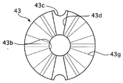
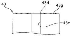
- FIG. 3 is a schematic diagram illustrating a state in which a radial recess of Example 1 of Example 1 is crushed. It is a schematic diagram which shows a mode that the radial direction recessed part of a comparative example is crushed and processed. It is the figure which looked at the armature of the other Example from the axial direction one end side.
- FIG. 1 is a cross-sectional view of the pressure reducing valve 1.
- the pressure reducing valve 1 includes a coil 40 that generates electromagnetic force when energized, a valve body 51 that is disposed inside a yoke 41 that houses the coil 40, a fixed core 42 that is fixed to one end of the valve body 51, a valve
- the armature 43 is configured to be movable in the axial direction in the body 51, and a seat member 44 having a seat portion 44b on which the valve body 43a of the armature 43 sits.
- the sliding direction of the armature 43 is defined as the axial direction
- the direction in which the armature 43 moves in the valve opening direction when the coil 40 is energized is defined as one end side in the axial direction
- the armature 43 is The direction of movement in the valve closing direction is defined as the other axial end side.
- a valve mounting hole 32 into which the pressure reducing valve 1 is inserted is formed in the housing 31. A part of the other end side of the pressure reducing valve 1 is inserted and fixed in the valve mounting hole 32.
- the valve body 51 is formed in a cylindrical shape from a nonmagnetic material.
- a fixed core 42 is fixed to the inner periphery of one end side of the valve body 51.
- An armature 43 is inserted into the inner periphery of the valve body 51 and on the other end side of the fixed core 42.
- the amateur 43 is provided so as to be movable in the axial direction in the valve body 51.
- One end face of the amateur 43 is provided with a spring accommodation hole 43b drilled toward the other end side.
- a coil spring 49 is accommodated in the spring accommodation hole 43b.
- the coil spring 49 is disposed between the other end surface of the fixed core 42 and the bottom of the spring accommodating hole 43b.
- the coil spring 49 biases the armature 43 toward the seat portion 44b side of the seat member 44.
- the sheet member 44 is formed in a bottomed cup shape.
- the sheet member 44 has an opening on the other end side and a bottom portion on one end side.
- a through hole 44 a that communicates the outside and the inside of the sheet member 44 is formed at the bottom of the sheet member 44.
- a sheet portion 44b is formed on one end face of the bottom portion of the sheet member 44 and on the outer peripheral side of the through hole 44a.
- the sheet portion 44b is formed in a mortar shape coaxially with the through hole 44a.
- the outer diameter on the other end side of the sheet member 44 is formed smaller than the outer diameter on the one end side.
- the sheet member 44 is accommodated in the cup member 45.
- the cup member 45 is formed in a bottomed cup shape.
- the cup member 45 has an opening on one end side and a bottom portion on the other end side.
- a through hole 45 a that communicates the outside and the inside of the cup member 45 is formed at the bottom of the cup member 45.
- a through-hole 45b that connects the outside and the inside of the cup member 45 is formed.
- a step is provided on the inner peripheral surface of the cup member 45 on the other end side with respect to the through hole 45b (step portion 45c).
- the cup member 45 is formed such that the inner diameter on the other end side (small diameter portion 45d) is smaller than the inner diameter on one end side (large diameter portion 45e) with respect to the stepped portion 45c.
- the sheet member 44 is press-fitted into the inner periphery of the large diameter portion 45e of the cup member 45.
- the space on the through hole 45 a side and the space on the through hole 45 b side are isolated by the sheet member 44.
- the coil 40 When the coil 40 is energized, a magnetic force is generated in the fixed core 42 and the armature 43.
- the armature 43 is attracted to one end side by the magnetic force of the fixed core 42, and the valve body 43a is separated from the seat portion 44b. Thereby, the through hole 45a and the through hole 45b are communicated with each other through the through hole 44a.
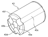
- FIG. 2 is a perspective view of the amateur 43.
- FIG. 3 is a perspective view of the amateur 43.
- FIG. 4 is a view of the armature 43 as seen from one end side in the axial direction.
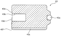
- FIG. 5 is a sectional view of the amateur 43.
- On the outer periphery of the amateur 43 there is formed an axial liquid passage 43c that communicates one end side in the axial direction with the other end side.
- Three axial liquid passages 43c are formed substantially evenly in the circumferential direction.
- a radial recess 43d of a concave groove is formed in the radial direction on the surface of the amateur 43 at one axial end side.
- the radial recess 43d communicates the axial liquid path 43c and the spring accommodation hole 43b. That is, three radial recesses 43d are formed substantially equally in the circumferential direction.
- the width of the radial recess 43d on the axial liquid path 43c side is formed wider than the width of the axial liquid path 43c.
- the depth of the radial recess 43d is formed shallower than the depth of the axial liquid passage 43c.
- An annular liquid passage 43e is formed over the entire periphery of the opening edge of the spring accommodation hole 43b. A part of the annular liquid passage 43e includes a radial recess 43d.
- a portion of the radial recess 43d that overlaps the annular liquid passage 43e is formed so that the width decreases from the outer diameter side to the inner diameter side of the armature 43.
- the depth of the annular liquid passage 43e between adjacent radial recesses 43d is formed deeper on the inner peripheral side (opening edge side of the spring accommodating hole 43b) than on the outer peripheral side.
- the annular liquid passage 43e between the adjacent radial recesses 43d is formed by an inclined surface that is inclined from the surface on one end side of the armature 43 toward the housing recess.
- the depth of the annular liquid passage 43e between the adjacent radial recesses 43d is formed to be shallower than the depth of the radial recess 43d.
- the radial recess 43d is formed by forging (crushing) a surface on one end side of the armature 43. Before the radial concave portion 43d is formed, a chamfered portion 43f is formed between the surface on one end side of the armature 43 and the outer surface (outer peripheral surface). The surplus (burr) generated when the surface on one end side of the armature 43 is crushed to form the radial recess 43d escapes into the space between the mold and the chamfered portion 43f.
- the cross-sectional area of the radial recess 43d is determined by the groove width and depth of the radial recess 43d. That is, if the groove width of the radial recess 43d is reduced, the depth needs to be increased. On the other hand, if the depth of the radial recess 43d is reduced, it is necessary to increase the groove width.
- the amount of surplus generated during the crushing process is determined according to the volume inside the radial recess 43d.
- the axial length of the radial recess 43d is determined by the distance from the outer peripheral surface of the armature 43 to the opening of the spring accommodating hole 43b. That is, if the cross-sectional area of the radial recess 43d is designed to be constant, the amount of surplus will be generated in an approximately equal amount regardless of whether the groove width is widened or narrowed.
- FIG. 6 is a schematic diagram showing a state in which the radial recess 43d of Example 1 is crushed.
- Example 1 the groove width of the radial recess 43d is wider than the groove width of the axial liquid path 43c, and the depth of the radial recess 43d is shallower than the depth of the axial liquid path 43c.
- the groove width of the radial recess 43d is formed wider than the groove width of the axial liquid passage 43c, the volume of the space between the mold and the chamfer 43f in the range of the groove width of the radial recess 43d is increased. It can be secured sufficiently. Thereby, it is possible to secure a space for escape of surplus material generated during crushing.
- FIG. 7 is a schematic diagram showing a state in which the radial recess 43d of the comparative example is crushed.
- the comparative example shows an example in which the groove width of the radial recess 43d is narrower than the groove width of the axial liquid path 43c. Since the groove width of the radial recess 43d is reduced, the radial recess 43d of the comparative example is deeper than the depth of the radial recess 43d of the first embodiment. In the comparative example, since the groove width of the radial recess 43d is narrower than the groove width of the axial liquid passage 43c, the volume of the space between the mold and the chamfer 43f in the range of the groove width of the radial recess 43d is sufficient. Can not be secured. As a result, it is not possible to secure a space for escape of surplus material generated during crushing. The surplus that could not be escaped strongly presses the mold, increasing the load on the mold. In addition, excess wall may leak from the gaps in the mold, resulting in burrs.
- the groove width of the radial recess 43d is formed narrower than the groove width of the axial liquid passage 43c. Further, the depth of the radial recess 43d is formed to be shallower than the depth of the axial liquid passage 43c. This makes it possible to reduce the depth while securing the volume inside the radial recess 43d.
- the attractive force between the fixed core 42 and the amateur 43 is inversely proportional to the square of the distance. Therefore, the area of the radial recess 43d on the one end side surface of the armature 43 is increased, but a decrease in the suction force between the fixed core 42 and the armature 43 is suppressed by reducing the depth of the radial recess 43d. can do.
- the armature 43 is formed with the axial liquid passage 43c and the radial recess 43d.
- the radial concave portion 43d is formed by pressing the surface on one end side of the armature 43.
- a chamfered portion 43f was formed between the surface on one end side of the amateur 43 and the outer peripheral surface. The surplus generated when the radial recess 43d is formed is positioned in the chamfer 43f. Thereby, it can suppress that the surplus wall inhibits the flow of hydraulic fluid.
- Example 1 the annular liquid passage 43e was formed continuously along the opening edge of the spring accommodation hole 43b.
- the working fluid can communicate with the inside and outside of the spring housing hole 43b from the entire circumference of the opening of the spring housing hole 43b, and a good flow of the working fluid can be ensured.
- the annular liquid passage 43e is formed including the radial recess 43d. Since the annular liquid passage 43e can be formed by diverting the radial recess 43d, the annular liquid passage 43e can be easily formed.
- the depth of the annular liquid path 43e between the adjacent radial recesses 43d is formed to be shallower than the depth of the radial recess 43d.
- the annular liquid passage 43e is formed so as to be inclined so that the spring accommodating hole 43b is deeper than the outer peripheral side. Since the depth of the outer peripheral side having a large area in the annular liquid passage 43e can be reduced, a reduction in the suction force between the fixed core 42 and the amateur 43 can be suppressed.
- a plurality of radial recesses 43d are formed in the circumferential direction of the armature 43. Thereby, since the cross-sectional area of one radial recess 43d can be reduced, the depth of the radial recess 43d can be reduced.
- Example 1 the portion of the radial recess 43d that overlaps the annular liquid passage 43e is formed so that the width decreases from the outer diameter side to the inner diameter side of the armature 43. It is possible to reduce the area of the radial recess 43d that is deeper than the annular liquid passage 43e. Therefore, it is possible to suppress a decrease in the suction force between the fixed core 42 and the amateur 43.
- the portion where the area of the radial recess 43d is small is a portion of the radial recess 43d that overlaps the annular liquid path 43e, and the working fluid flows also in the annular liquid path 43e, so the flow rate of the working fluid is sufficiently high Can be secured.
- a coil 40 that generates a magnetic field when energized a valve body 51 made of a non-magnetic cylindrical member disposed on the inner periphery of the coil 40, and a fixed core 42 fixed to one end of the valve body 51
- the armature 43 is arranged in the valve body 51 so that one end side faces the fixed core 42, and has a valve body 43a on the other end side, and moves in the valve body 51 in the axial direction toward the fixed core 42 when the coil is energized.
- a seat portion 44b that is disposed in the valve body 51 on the other end side of the armature 43 and that can be brought into contact with and separated from the valve body 43a and that closes the flow path formed inside the valve body 51 at the time of contact.
- a coil spring 49 biasing member
- An axial liquid passage 43c that communicates with the end side, and from one end surface to the other end surface on one end surface
- An axial direction is formed between the spring accommodating hole 43b (accommodating recess) for accommodating the coil spring 49 and a fixed core 42 formed on one end surface and when the armature 43 moves in the axial direction.
- the liquid passage 43c communicates with the spring accommodating hole 43b, and at least the width of the connecting portion connected to the axial liquid passage 43c is wider than the axial liquid passage 43c and shallower than the depth of the axial liquid passage 43c and extends in the radial direction. And a radial recess 43d. Therefore, it is possible to suppress a decrease in suction force between the fixed core 42 and the amateur 43. Further, the pressure reducing valve 1 can be manufactured at low cost. Further, the operation of the amateur 43 can be stabilized.
- the amateur 43 includes a chamfered portion 43f formed between the one end surface and the outer surface,
- the radial recess 43d was formed by pressing one end face, and the chamfer 43f was configured so that the surplus generated by pressing was located. Therefore, it can suppress that the surplus wall inhibits the flow of hydraulic fluid.
- the annular liquid passage 43e was formed continuously along the opening edge of the spring accommodation hole 43b. Therefore, it is possible to ensure a good flow of the hydraulic fluid flowing into the spring accommodation hole 43b.
- the annular liquid passage 43e is formed including the radial recess 43d. Therefore, the annular liquid passage 43e can be easily formed.
- a plurality of radial recesses 43d are formed in the circumferential direction on one end surface of the armature 43, and the depth of the annular liquid passage 43e between adjacent radial recesses 43d is shallower than the depth of the radial recess 43d. It was like that. Therefore, it is possible to suppress a decrease in suction force between the fixed core 42 and the amateur 43.
- the annular liquid passage 43e between the adjacent radial recesses 43d is formed by an inclined surface that is formed deeper at the opening edge of the spring accommodating hole 43b than the outer periphery and is inclined from one end surface toward the spring accommodating hole 43b. did. Therefore, it is possible to suppress a decrease in suction force between the fixed core 42 and the amateur 43.
- a plurality of radial recesses 43 d are formed in the circumferential direction of the armature 43. Therefore, it is possible to suppress a decrease in suction force between the fixed core 42 and the amateur 43.
- a plurality of radial recesses 43d are formed in the circumferential direction, the radial recesses 43d are narrower on the inner diameter side than the outer diameter side, and the narrowed inner diameter side parts are connected to adjacent radial recesses 43d.
- the annular liquid path 43e is provided, and the depth of the annular liquid path 43e is formed to be shallower than the depth of the radial recess 43d. Therefore, it is possible to suppress a decrease in suction force between the fixed core 42 and the amateur 43.
- the annular liquid passage 43e between the adjacent radial recesses 43d is formed by an inclined surface that is formed deeper at the opening edge of the spring accommodation hole 43b than the outer periphery and is inclined from one end surface toward the spring accommodation hole 43b. did. Therefore, it is possible to suppress a decrease in suction force between the fixed core 42 and the amateur 43.
- a seat portion 44b that is disposed on the other end side of the armature 43 and that can be brought into contact with and separated from the valve body 43a and closes the flow path formed inside the valve body 51 at the time of contact, a fixed core 42 and one end side of the armature 43
- the armature 43 includes an axial liquid passage 43c that communicates between one end side and the other end side, and the coil spring 49 is accommodated along the axis of the armature 43 from one end surface.
- Spring accommodating hole 43b formed toward the other end surface and one end And is provided with a radial recess 43d (radial fluid path) that communicates between the axial liquid path 43c and the spring accommodating hole 43b, and the radial recess 43d has a width of the connecting portion connected to the axial liquid path 43c. It is wider than the directional liquid passage 43c, and the depth of the radial recess 43d is less than the deepest portion of the axial liquid passage 43c. Therefore, it is possible to suppress a decrease in suction force between the fixed core 42 and the amateur 43. Further, the pressure reducing valve 1 can be manufactured at low cost. Further, the operation of the amateur 43 can be stabilized.
- the amateur 43 includes a chamfered portion 43f formed between the one end surface and the outer peripheral surface,
- the radial concave portion 43d was formed by forging, and the burr generated during the formation was accommodated in the chamfered portion 43f. Therefore, it can suppress that a burr inhibits the flow of hydraulic fluid.
- a plurality of radial recesses 43d are formed in the circumferential direction on one end face of the armature 43, An annular liquid passage 43e (connection liquid passage) formed by connecting adjacent radial concave portions 43d was formed along the opening edge of the spring accommodation hole 43b. Therefore, it is possible to ensure a good flow of the hydraulic fluid flowing into the spring accommodation hole 43b.
- the depth of the annular liquid passage 43e is formed to be shallower than the depth of the radial recess 43d. Therefore, it is possible to suppress a decrease in suction force between the fixed core 42 and the amateur 43.
- connection liquid path has an inclined surface that is formed deeper at the opening edge of the spring accommodating hole 43b than the outer periphery, and is inclined from the one end surface toward the spring accommodating hole 43b. Therefore, it is possible to suppress a decrease in suction force between the fixed core 42 and the amateur 43.
- valve body 51 made of a nonmagnetic cylindrical member fixed to a valve mounting hole 32 (mounting hole) formed in the housing 31 and disposed on the inner periphery of the coil 40 that generates a magnetic field when energized;
- the fixed body 42 attached to one end side of the valve body 51, the one end side is arranged to face the fixed core 42, the other end side is provided with a valve body 43a, and the valve body faces the fixed core 42 when the coil 40 is energized.
- 51 is a cylindrical armature 43 that moves in the axial direction in 51, and a seat that is disposed on the other end side of the armature 43 and that can contact and separate from the valve body 43a and closes the flow path formed inside the valve body 51 at the time of contact.
- a pressure reducing valve 1 for a hydraulic pressure control device having a portion 44b and a coil spring 49 contracted between the fixed core 42 and one end of the armature 43.
- a radial recess 43d radial fluid path
- the pressure reducing valve 1 can be manufactured at low cost. Further, the operation of the amateur 43 can be stabilized.
- the width of the connecting portion connected to the axial liquid passage 43c of the radial recess 43d is wider than that of the axial liquid passage 43c. Therefore, the effective cross-sectional area of the radial recess 43d can be ensured, so that the working fluid can be circulated favorably.
- the amateur 43 includes a chamfered portion 43f formed between the one end surface and the outer surface, The radial concave portion 43d was formed by pressing one end surface, and the chamfered portion 43f was configured such that the surplus generated by the pressing was located. Therefore, it can suppress that the surplus wall inhibits the flow of hydraulic fluid.
- a plurality of radial recesses 43d are formed in the circumferential direction on one end face of the armature 43, An annular liquid passage 43e (connection liquid passage) formed by connecting adjacent radial concave portions 43d was formed along the opening edge of the spring accommodation hole 43b. Therefore, it is possible to ensure a good flow of the hydraulic fluid flowing into the spring accommodation hole 43b.
- the depth of the annular liquid passage 43e is formed to be shallower than the depth of the radial recess 43d. Therefore, it is possible to suppress a decrease in suction force between the fixed core 42 and the amateur 43.
- the annular liquid passage 43e has an inclined surface that is formed deeper at the opening edge of the spring accommodation hole 43b than the outer periphery and is inclined from the one end surface toward the spring accommodation hole 43b. Therefore, it is possible to suppress a decrease in suction force between the fixed core 42 and the amateur 43.
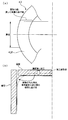
- FIG. 8 is a view of the amateur 43 as viewed from one end side in the axial direction.
- FIG. 9 is a view of a part of one end side of the armature 43 in the axial direction as seen from the radial direction.
- the groove width of the radial recess 43d is increased from the outer peripheral side of the armature 43 toward the inner peripheral side.
- the annular liquid passage 43e has been abolished.
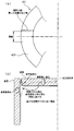
- FIG. 10 is a view of the amateur 43 as viewed from one end side in the axial direction.
- FIG. 11 is a view of a part of one end side of the armature 43 in the axial direction as seen from the radial direction.
- the groove width of the radial recess 43d is reduced as it goes from the outer peripheral side to the inner peripheral side of the armature 43.
- the annular liquid passage 43e has been abolished.
- Valve for pressure reduction (solenoid valve), 32 Valve mounting hole (mounting hole), 40 coils, 42 Fixed core (fixed core), 43 amateur, 43a valve body, 43b Spring receiving hole (receiving recess) (receiving hole), 43c Axial fluid path, 43d radial recess (radial fluid path), 43e annular fluid path (connection fluid path), 43f chamfered part, 44b seat part, 49 coil spring, 51 valve body
Landscapes
- Engineering & Computer Science (AREA)
- Physics & Mathematics (AREA)
- Electromagnetism (AREA)
- General Engineering & Computer Science (AREA)
- Mechanical Engineering (AREA)
- Power Engineering (AREA)
- Transportation (AREA)
- Magnetically Actuated Valves (AREA)
- Valves And Accessory Devices For Braking Systems (AREA)
- Electromagnets (AREA)
Abstract
アマチュアの作動の阻害を抑制することができる電磁弁を提供すること。 アマチュアは、一端側と他端側を連通する軸方向液路と、一端面に一端面から他端面に向けて形成され付勢部材を収容するスプリング収容孔と、一端面に形成され、アマチュアが軸方向に移動したときに固定コアとの間に流路を構成するよう軸方向液路とスプリング収容孔を連通し、少なくとも、軸方向液路と接続する接続部の幅が軸方向液路より広く、軸方向液路よりの深さより浅く形成し径方向に延在する径方向凹部と、を備える。
Description
本発明は、電磁弁に関する。
この種の技術としては、下記の特許文献1に記載の技術が開示されている。特許文献1には、磁気コアに突起を形成し、磁気コアと磁気アマチュアとの間に流路を形成したものが開示されている。この流路は、磁気アマチュアの外周に軸方向形成された液路と、戻しスプリング収容孔とを連通し、弁座-収容体側のブレーキ液を戻しスプリング収容孔に流通可能になっている。
特許文献1に記載の発明では、磁気アマチュアの回転位置によっては、流路の位置と液路の位置がずれてしまい、ブレーキ液の流通がしにくくなるため、磁気アマチュアの作動を阻害するおそれがあった。
本発明は、上記問題に着目されたもので、その目的とするところは、アマチュアの作動の阻害を抑制することができる電磁弁を提供することである。
本発明は、上記問題に着目されたもので、その目的とするところは、アマチュアの作動の阻害を抑制することができる電磁弁を提供することである。
上記目的を達成するため。本発明の第一実施形態では、アマチュアは、一端側と他端側を連通する軸方向液路と、一端面に一端面から他端面に向けて形成され付勢部材を収容するスプリング収容孔と、一端面に形成され、アマチュアが軸方向に移動したときに固定コアとの間に流路を構成するよう軸方向液路とスプリング収容孔を連通し、少なくとも、軸方向液路と接続する接続部の幅が軸方向液路より広く、軸方向液路の深さより浅く形成し径方向に延在する径方向凹部とを有するようにした。
また第二実施形態では、アマチュアは、一端側と他端側を連通する軸方向液路と、コイルスプリングが収容され一端面からアマチュアの軸に沿って他端面に向けて形成されたスプリング収容孔と、一端面に形成され、軸方向液路とスプリング収容孔を連通する径方向液路を備え、径方向液路は、軸方向液路と接続する接続部の幅が軸方向液路より幅が広く、径方向液路の深さは軸方向液路の最深部の深さ以下に形成した。
また第三実施形態では、アマチュアの一端面の中心部を含む領域からアマチュアの軸方向に沿って所定長さ形成されコイルスプリングが収容されるスプリング収容孔と、アマチュアの一端側と他端側を連通する軸方向液路と、アマチュアの一端面に形成され、軸方向液路とスプリング収容孔内を接続する径方向液路を備え、径方向液路の深さは軸方向液路の最深部の深さ以下に形成した。
よって、第一実施形態ないし第三実施形態では、アマチュアの作動の阻害を抑制することができる。
〔実施例1〕
[減圧用バルブの構成]
実施例1の減圧用バルブ1について説明する。図1は減圧用バルブ1の断面図である。減圧用バルブ1は通電により電磁力を発生するコイル40と、コイル40を収納するヨーク41の内側に配置されたバルブボディ51と、バルブボディ51の一端側に固定された固定コア42と、バルブボディ51内を軸方向に移動可能に設けられたアマチュア43と、アマチュア43の弁体43aが座るシート部44bを有するシート部材44とから構成されている。
以下の説明において、アマチュア43の摺動方向を軸方向と定義し、コイル40の通電時にアマチュア43が開弁方向に動く向きを軸方向一端側と定義し、コイル40の非通電時にアマチュア43が閉弁方向に動く向きを軸方向他端側と定義する。
ハウジング31に減圧用バルブ1が挿入されるバルブ取り付け孔32が形成されている。このバルブ取り付け孔32に減圧用バルブ1の他端側の一部が挿入されて固定されている。
バルブボディ51は非磁性体材料により円筒状に形成されている。バルブボディ51の一端側の内周に固定コア42が固定されている。バルブボディ51の内周であって固定コア42の他端側には、アマチュア43が挿入されている。アマチュア43はバルブボディ51内を軸方向に移動可能に設けられている。
アマチュア43の一端面には、他端側に向かって穿設されたスプリング収容孔43bが設けられている。スプリング収容孔43bにはコイルスプリング49が収容されている。コイルスプリング49は、固定コア42の他端面とスプリング収容孔43bの底部との間に配置されている。コイルスプリング49は、アマチュア43をシート部材44のシート部44b側に付勢している。アマチュア43がシート部44b側に移動すると、弁体43aがシート部44bに当接する。これにより、バルブボディ51内の流路が閉塞される。
アマチュア43の一端面には、他端側に向かって穿設されたスプリング収容孔43bが設けられている。スプリング収容孔43bにはコイルスプリング49が収容されている。コイルスプリング49は、固定コア42の他端面とスプリング収容孔43bの底部との間に配置されている。コイルスプリング49は、アマチュア43をシート部材44のシート部44b側に付勢している。アマチュア43がシート部44b側に移動すると、弁体43aがシート部44bに当接する。これにより、バルブボディ51内の流路が閉塞される。
シート部材44は、有底カップ状に形成されている。シート部材44は、他端側が開口し、一端側が底部を形成している。シート部材44の底部には、シート部材44の外側と内側とを連通する貫通孔44aが形成されている。シート部材44の底部の一端面であって貫通孔44aの外周側にはシート部44bが形成されている。シート部44bは、貫通孔44aと同軸上にすり鉢状に形成されている。シート部材44の他端側の外径は一端側の外径に比べて小さく形成されている。シート部材44は、カップ部材45内に収容されている。
カップ部材45は、有底カップ状に形成されている。カップ部材45は、一端側が開口し、他端側が底部を形成している。カップ部材45の底部には、カップ部材45の外側と内側とを連通する貫通孔45aが形成されている。カップ部材45の側面には、カップ部材45の外側と内側とを連通する貫通孔45bが形成されている。カップ部材45の内周面であって貫通孔45bよりも他端側において段がついている(段部45c)。カップ部材45は、段部45cよりも他端側(小径部45d)の内径が一端側(大径部45e)の内径よりも小さく形成されている。シート部材44は、カップ部材45の大径部45eの内周に圧入されている。カップ部材45は、シート部材44により貫通孔45a側の空間と貫通孔45b側の空間とが隔絶されている。
コイル40に通電すると固定コア42およびアマチュア43に磁力が発生する。固定コア42の磁力によりアマチュア43が一端側に吸引され、弁体43aがシート部44bから離間する。これにより、貫通孔44aを介して貫通孔45aと貫通孔45bとの間が連通される。
[アマチュアの構成]
アマチュア43の構成について説明する。図2はアマチュア43の斜視図である。図3はアマチュア43の斜視図である。図4はアマチュア43を軸方向一端側から見た図である。図5はアマチュア43の断面図である。
アマチュア43の外周には、軸方向一端側と他端側とを連通する軸方向液路43cが形成されている。軸方向液路43cは周方向にほぼ均等に3本形成されている。アマチュア43の軸方向一端側の面には放射方向に凹状溝の径方向凹部43dが形成されている。径方向凹部43dは、軸方向液路43cとスプリング収容孔43bとを連通している。つまり、径方向凹部43dは、周方向にほぼ均等に3本形成されている。径方向凹部43dの軸方向液路43c側の幅は、軸方向液路43cの幅よりも広く形成されている。径方向凹部43dの深さは、軸方向液路43cの深さよりも浅く形成されている。
スプリング収容孔43bの開口縁には全周に渡って環状液路43eが形成されている。環状液路43eの一部は径方向凹部43dを含んで構成されている。径方向凹部43dのうち、環状液路43eと重なる部分は、アマチュア43の外径側から内径側に向かって幅が狭くなるように形成されている。隣り合う径方向凹部43dの間の環状液路43eの深さは、外周側よりも内周側(スプリング収容孔43bの開口縁側)の方が深く形成されている。隣り合う径方向凹部43dの間の環状液路43eは、アマチュア43の一端側の面から収容凹部に向かって傾斜する傾斜面によって形成されている。隣り合う径方向凹部43dの間の環状液路43eの深さは、径方向凹部43dの深さよりも浅く形成されている。
[径方向凹部の形成]
径方向凹部43dは、アマチュア43の一端側の面を鍛造(潰し加工)することにより形成されている。径方向凹部43dが形成される以前に、アマチュア43の一端側の面と外側面(外周面)との間には、面取り部43fが形成されている。径方向凹部43dを形成するためにアマチュア43の一端側の面を潰し加工する際に発生した余肉(バリ)は、金型と面取り部43fとの間の空間内に逃げる。
径方向凹部43dを流れる作動液の流量を確保するためには、径方向凹部43dの断面積(径方向凹部43dの軸方向に対して垂直に切ったときの断面積)を確保する必要がある。径方向凹部43dの断面積は、径方向凹部43dの溝幅と深さで決まる。つまり、径方向凹部43dの溝幅を細くすると、深さを深くする必要がある。一方、径方向凹部43dの深さを浅くすると、溝幅を広くする必要がある。
潰し加工する際に発生する余肉の量は、径方向凹部43dの内部の体積に応じて決まる。また、径方向凹部43dの軸方向長さは、アマチュア43の外周面からスプリング収容孔43bの開口部までの距離で決まる。つまり、径方向凹部43dの断面積を一定に保つように設計すれば溝幅を広くしても狭くしても余肉の量は、ほぼ等しい量発生することとなる。
図6は実施例1の径方向凹部43dを潰し加工する様子を示す模式図である。実施例1では、径方向凹部43dの溝幅を軸方向液路43cの溝幅よりも広くし、径方向凹部43dの深さを軸方向液路43cの深さよりも浅くするようにした。実施例1では、径方向凹部43dの溝幅を軸方向液路43cの溝幅より広く形成したため、径方向凹部43dの溝幅の範囲における金型と面取り部43fとの間の空間の体積を十分に確保することができる。これにより、潰し加工のときに発生する余肉が逃げる空間を確保することができる。
図7は比較例の径方向凹部43dを潰し加工する様子を示す模式図である。比較例では、径方向凹部43dの溝幅を軸方向液路43cの溝幅より狭くした例を示している。径方向凹部43dの溝幅が狭くなった分、比較例の径方向凹部43dでは実施例1の径方向凹部43dの深さよりも深くなっている。比較例では、径方向凹部43dの溝幅を軸方向液路43cの溝幅より狭く形成したため、径方向凹部43dの溝幅の範囲における金型と面取り部43fとの間の空間の体積を十分に確保することができない。これにより、潰し加工のときに発生する余肉が逃げる空間を確保することができない。逃げることができなかった余肉は、金型を強く押圧するため、金型への負荷が大きくなる。また、金型の隙間から余肉が漏れて、バリとなることがある。
[作用]
実施例1では、径方向凹部43dの溝幅を軸方向液路43cの溝幅より狭く形成するようにした。また、径方向凹部43dの深さを軸方向液路43cの深さより浅く形成するようにした。これにより、径方向凹部43dの内部の体積を確保しつつ、深さを浅くすることができる。固定コア42とアマチュア43との間の吸引力は、距離の二乗に反比例する。そのため、アマチュア43の一端側の面における径方向凹部43dの面積は大きくなるが、径方向凹部43dの深さを浅くすることによって、固定コア42とアマチュア43との間の吸引力の低下を抑制することができる。また固定コア42とアマチュア43との間の吸引力の低下を抑制することができるため、コイル40等を小さくすることができ、減圧用バルブ1を安価に製造することができる。
実施例1では、アマチュア43に軸方向液路43cと径方向凹部43dを形成するようにした。アマチュア43に液路を集約したことで作動液を流通させやすくなり、アマチュア43の作動を安定させることができる。
実施例1では、径方向凹部43dをアマチュア43の一端側の面を押圧することにより形成するようにした。アマチュア43の一端側の面と外周面との間に面取り部43fを形成した。径方向凹部43dを形成する際に発生する余肉は面取り部43fに位置するようにした。これにより、余肉が作動液の流れを阻害することを抑制することができる。
実施例1では、スプリング収容孔43bの開口縁に沿って連続して環状液路43eを形成した。作動液が、スプリング収容孔43bの開口部の全周からスプリング収容孔43bの内外に連通することができ、作動液の良好な流れを確保することができる。
実施例1では、環状液路43eを径方向凹部43dを含んで形成するようにした。環状液路43eを径方向凹部43dを流用して形成することができるため、環状液路43eを容易に形成することができる。
実施例1では、隣り合う径方向凹部43dの間の環状液路43eの深さを、径方向凹部43dの深さよりも浅く形成するようにした。環状液路43eの深さを浅く形成することにより、固定コア42とアマチュア43との間の吸引力の低下を抑制することができる。
実施例1では、環状液路43eを外周側よりスプリング収容孔43bの方が深くなるように傾斜して形成するようにした。環状液路43eのうち面積が広い外周側の深さを浅くすることができるため、固定コア42とアマチュア43との間の吸引力の低下を抑制することができる。
実施例1では、径方向凹部43dをアマチュア43の周方向に複数形成した。これにより、1つの径方向凹部43dの断面積を小さくすることができるため、径方向凹部43dの深さを浅くすることができる。したがって、固定コア42とアマチュア43との間の吸引力の低下を抑制することができる。
実施例1では、径方向凹部43dのうち環状液路43eと重なる部分をアマチュア43の外径側から内径側に向かって幅が狭くなるように形成した。環状液路43eに比べて深さが深い径方向凹部43dの面積を小さくすることができる。したがって、固定コア42とアマチュア43との間の吸引力の低下を抑制することができる。なお、径方向凹部43dの面積が小さくなる部分は、径方向凹部43dのうち環状液路43eと重なる部分であり、作動液は環状液路43e内にも流れるため、作動液の流量は十分に確保することができる。
[効果]
(1) 通電時に磁界を発生するコイル40と、コイル40の内周に配置された非磁性体の筒状部材からなるバルブボディ51と、バルブボディ51の一端側に固定された固定コア42と、一端側が固定コア42に対向するようバルブボディ51内に配置され、他端側には弁体43aを備え、コイル通電時に固定コア42に向けてバルブボディ51内を軸方向に移動するアマチュア43と、バルブボディ51内であって、アマチュア43の他端側に配置され、弁体43aと接離可能で当接時にバルブボディ51内部に形成された流路を閉塞するシート部44bと、固定コア42の他端側とアマチュア43の一端側との間にアマチュア43をシート部44bの方向に付勢するコイルスプリング49(付勢部材)と、を有し、アマチュア43は、一端側と他端側を連通する軸方向液路43cと、一端面に一端面から他端面に向けて形成されコイルスプリング49を収容するスプリング収容孔43b(収容凹部)と、一端面に形成され、アマチュア43が軸方向に移動したときに固定コア42との間に流路を構成するよう軸方向液路43cとスプリング収容孔43bを連通し、少なくとも、軸方向液路43cと接続する接続部の幅が軸方向液路43cより広く、軸方向液路43cの深さより浅く形成し径方向に延在する径方向凹部43dとを有するようにした。
よって、固定コア42とアマチュア43との間の吸引力の低下を抑制することができる。また、減圧用バルブ1を安価に製造することができる。また 、アマチュア43の作動を安定させることができる。
(2) アマチュア43は、一端面と外側面との間に形成された面取り部43fを備え、
径方向凹部43dを、一端面を押圧して形成し、面取り部43fに押圧により発生した余肉が位置するよう構成した。
よって、余肉が作動液の流れを阻害することを抑制することができる。
(3) スプリング収容孔43bの開口縁に沿って連続して環状液路43eを形成した。
よって、スプリング収容孔43bに流れ込む作動液の良好な流れを確保することができる。
(4) 環状液路43eを径方向凹部43dを含んで形成した。
よって、環状液路43eを容易に形成することができる。
(5) 径方向凹部43dは、アマチュア43の一端面に円周方向に複数個所形成され、隣り合う径方向凹部43dの間の環状液路43eの深さは径方向凹部43dの深さより浅く形成されているようにした。
よって、固定コア42とアマチュア43との間の吸引力の低下を抑制することができる。
(6) 隣り合う径方向凹部43dの間の環状液路43eは、外周よりスプリング収容孔43bの開口縁の方が深く形成され、一端面からスプリング収容孔43bに向かって傾斜する傾斜面によって形成した。
よって、固定コア42とアマチュア43との間の吸引力の低下を抑制することができる。
(7) 径方向凹部43dを、アマチュア43の周方向に複数形成した。
よって、固定コア42とアマチュア43との間の吸引力の低下を抑制することができる。
(8) 径方向凹部43dを周方向に複数形成し、径方向凹部43dは外径側の幅よりも内径側の幅を狭くし、狭くなった内径側部を隣り合う径方向凹部43dを接続する環状液路43eを備え、環状液路43eの深さを径方向凹部43dの深さよりも浅く形成した。
よって、固定コア42とアマチュア43との間の吸引力の低下を抑制することができる。
(9) 隣り合う径方向凹部43dの間の環状液路43eは、外周よりスプリング収容孔43bの開口縁の方が深く形成され、一端面からスプリング収容孔43bに向かって傾斜する傾斜面によって形成した。
よって、固定コア42とアマチュア43との間の吸引力の低下を抑制することができる。
よって、固定コア42とアマチュア43との間の吸引力の低下を抑制することができる。
(7) 径方向凹部43dを、アマチュア43の周方向に複数形成した。
よって、固定コア42とアマチュア43との間の吸引力の低下を抑制することができる。
(8) 径方向凹部43dを周方向に複数形成し、径方向凹部43dは外径側の幅よりも内径側の幅を狭くし、狭くなった内径側部を隣り合う径方向凹部43dを接続する環状液路43eを備え、環状液路43eの深さを径方向凹部43dの深さよりも浅く形成した。
よって、固定コア42とアマチュア43との間の吸引力の低下を抑制することができる。
(9) 隣り合う径方向凹部43dの間の環状液路43eは、外周よりスプリング収容孔43bの開口縁の方が深く形成され、一端面からスプリング収容孔43bに向かって傾斜する傾斜面によって形成した。
よって、固定コア42とアマチュア43との間の吸引力の低下を抑制することができる。
(10) 通電時に磁界を発生するコイル40の内周に配置された非磁性体の筒状部材からなるバルブボディ51と、バルブボディ51の一端側に取り付けられた固定コア42(固定鉄心)と、一端側が固定コア42に対向するよう配置され、他端側には弁体43aを備え、コイル40通電時に固定コア42に向けてバルブボディ51内を軸方向に移動する円柱状のアマチュア43と、アマチュア43の他端側に配置され、弁体43aと接離可能で当接時にバルブボディ51内部に形成された流路を閉塞するシート部44bと、固定コア42とアマチュア43の一端側との間に縮設されたコイルスプリング49を有し、アマチュア43は、一端側と他端側を連通する軸方向液路43cと、コイルスプリング49が収容され一端面からアマチュア43の軸に沿って他端面に向けて形成されたスプリング収容孔43bと、一端面に形成され、軸方向液路43cとスプリング収容孔43bを連通する径方向凹部43d(径方向液路)を備え、径方向凹部43dは、軸方向液路43cと接続する接続部の幅が軸方向液路43cより幅が広く、径方向凹部43dの深さは軸方向液路43cの最深部の深さ以下に形成した。
よって、固定コア42とアマチュア43との間の吸引力の低下を抑制することができる。また、減圧用バルブ1を安価に製造することができる。また、アマチュア43の作動を安定させることができる。
(11)アマチュア43は、一端面と外周面との間に形成された面取り部43fを備え、
径方向凹部43dを鍛造により形成し、形成時に発生したバリを面取り部43fに収容するように構成した。
よって、バリが作動液の流れを阻害することを抑制することができる。
よって、固定コア42とアマチュア43との間の吸引力の低下を抑制することができる。また、減圧用バルブ1を安価に製造することができる。また、アマチュア43の作動を安定させることができる。
(11)アマチュア43は、一端面と外周面との間に形成された面取り部43fを備え、
径方向凹部43dを鍛造により形成し、形成時に発生したバリを面取り部43fに収容するように構成した。
よって、バリが作動液の流れを阻害することを抑制することができる。
(12) 径方向凹部43dを、アマチュア43の一端面に円周方向に複数形成し、
スプリング収容孔43bの開口縁に沿って、隣り合う径方向凹部43d間を接続してなる環状液路43e(接続液路)を形成した。
よって、スプリング収容孔43bに流れ込む作動液の良好な流れを確保することができる。
(13) 環状液路43eの深さを径方向凹部43dの深さより浅く形成した。
よって、固定コア42とアマチュア43との間の吸引力の低下を抑制することができる。
(14) 接続液路は、外周よりスプリング収容孔43bの開口縁の方が深く形成され、一端面からスプリング収容孔43bに向かって傾斜する傾斜面を備えた。
よって、固定コア42とアマチュア43との間の吸引力の低下を抑制することができる。
(15) ハウジング31に形成されたバルブ取り付け孔32(取り付け孔)に固定され、通電時に磁界を発生するコイル40の内周に配置された非磁性体の筒状部材からなるバルブボディ51と、バルブボディ51の一端側に取り付けられた固定コア42と、一端側が固定コア42に対向するよう配置され、他端側には弁体43aを備え、コイル40通電時に固定コア42に向けてバルブボディ51内を軸方向に移動する円柱状のアマチュア43と、アマチュア43の他端側に配置され、弁体43aと接離可能で当接時にバルブボディ51内部に形成された流路を閉塞するシート部44bと、固定コア42とアマチュア43の一端側との間に縮設されたコイルスプリング49と、を有する液圧制御装置用の減圧用バルブ1(電磁弁)であって、アマチュア43の一端面の中心部を含む領域からアマチュア43の軸方向に沿って所定長さ形成されコイルスプリング49が収容されるスプリング収容孔43b(収容孔)と、アマチュア43の一端側と他端側を連通する軸方向液路43cと、アマチュア43の一端面に形成され、軸方向液路43cとスプリング収容孔43b内を接続する径方向凹部43d(径方向液路)と、を備え、径方向凹部43dの深さは軸方向液路43cの最深部の深さ以下に形成した。
よって、固定コア42とアマチュア43との間の吸引力の低下を抑制することができる。また、減圧用バルブ1を安価に製造することができる。また、アマチュア43の作動を安定させることができる。
(16) 径方向凹部43dの軸方向液路43cと接続する接続部の幅を軸方向液路43cより幅が広く形成した。
よって、径方向凹部43dの有効断面積を確保することができるため、作動液の流通を良好にすることができる。
(17) アマチュア43は、一端面と外側面との間に形成された面取り部43fを備え、
径方向凹部43dを、一端面を押圧して形成し、面取り部43fに押圧により発生した余肉が位置するように構成した。
よって、余肉が作動液の流れを阻害することを抑制することができる。
(18) 径方向凹部43dを、アマチュア43の一端面に円周方向に複数形成し、
スプリング収容孔43bの開口縁に沿って、隣り合う径方向凹部43d間を接続してなる環状液路43e(接続液路)を形成した。
よって、スプリング収容孔43bに流れ込む作動液の良好な流れを確保することができる。
(19) 環状液路43eの深さを径方向凹部43dの深さより浅く形成した。
よって、固定コア42とアマチュア43との間の吸引力の低下を抑制することができる。
(20) 環状液路43eは、外周よりスプリング収容孔43bの開口縁の方が深く形成され、一端面からスプリング収容孔43bに向かって傾斜する傾斜面を備えた。
よって、固定コア42とアマチュア43との間の吸引力の低下を抑制することができる。
〔他の実施例〕
以上、本発明を実施例1に基づいて説明してきたが、各発明の具体的な構成は実施例1に限定されるものではなく、発明の要旨を逸脱しない範囲の設計変更等があっても、本発明に含まれる。
以上、本発明を実施例1に基づいて説明してきたが、各発明の具体的な構成は実施例1に限定されるものではなく、発明の要旨を逸脱しない範囲の設計変更等があっても、本発明に含まれる。
(他の実施例1)
他の実施例1の減圧用バルブ1について説明する。実施例1と同じ構成については、同一の符号を付して説明を省略する。
[アマチュアの構成]
図8はアマチュア43を軸方向一端側から見た図である。図9はアマチュア43の軸方向一端側の一部を径方向から見た図である。
他の実施例1では、径方向凹部43dの溝幅をアマチュア43の外周側から内周側に向かうに連れて拡大するようにした。また環状液路43eは廃止した。径方向凹部43dをこのような形状とすることで、作動油の流通を良好にすることができる。
他の実施例1の減圧用バルブ1について説明する。実施例1と同じ構成については、同一の符号を付して説明を省略する。
[アマチュアの構成]
図8はアマチュア43を軸方向一端側から見た図である。図9はアマチュア43の軸方向一端側の一部を径方向から見た図である。
他の実施例1では、径方向凹部43dの溝幅をアマチュア43の外周側から内周側に向かうに連れて拡大するようにした。また環状液路43eは廃止した。径方向凹部43dをこのような形状とすることで、作動油の流通を良好にすることができる。
(他の実施例2)
他の実施例2の減圧用バルブ1について説明する。実施例1と同じ構成については、同一の符号を付して説明を省略する。
[アマチュアの構成]
図10はアマチュア43を軸方向一端側から見た図である。図11はアマチュア43の軸方向一端側の一部を径方向から見た図である。
他の実施例2では、径方向凹部43dの溝幅をアマチュア43の外周側から内周側に向かうに連れて縮小するようにした。また環状液路43eは廃止した。さらに隣り合う径方向凹部43dとの間には、放射状に伸びる複数の溝を設け、アマチュア43の軸方向一端側の面が波状となる波面43gを形成した。これにより、固定コア42とアマチュア43とを離間させやすくすることができる。
以上、本発明のいくつかの実施形態について説明してきたが、上述した発明の実施形態は、本発明の理解を容易にするためのものであり、本発明を限定するものではない。本発明は、その趣旨を逸脱することなく、変更、改良され得るとともに、本発明にはその均等物が含まれることはもちろんである。また、上述した課題の少なくとも一部を解決できる範囲、または、効果の少なくとも一部を奏する範囲において、特許請求の範囲および明細書に記載された各構成要素の任意の組み合わせ、または、省略が可能である。
本願は、2014年7月23日出願の日本特許出願番号2014-149381号に基づく優先権を主張する。2014年7月23日出願の日本特許出願番号2014-149381号の明細書、特許請求の範囲、図面及び要約書を含む全ての開示内容は、参照により全体として本願に組み込まれる。
1 減圧用バルブ(電磁弁)、32 バルブ取り付け孔(取り付け孔)、40 コイル、42 固定コア(固定鉄心)、43 アマチュア、43a 弁体、43b スプリング収容孔(収容凹部)(収容孔)、43c 軸方向液路、43d 径方向凹部(径方向液路)、43e 環状液路(接続液路)、43f 面取り部、44b シート部、49 コイルスプリング、51 バルブボディ
Claims (20)
- 電磁弁であって、
通電時に磁界を発生するコイルと、
前記コイルの内周に配置された非磁性体の筒状部材からなるバルブボディと、
前記バルブボディの一端側に固定された固定コアと、
一端側が前記固定コアに対向するよう前記バルブボディ内に配置され、他端側には弁体を備え、前記コイル通電時に前記固定コアに向けて前記バルブボディ内を軸方向に移動するアマチュアと、
前記バルブボディ内であって、前記アマチュアの他端側に配置され、前記弁体と接離可能で当接時に前記バルブボディ内部に形成された流路を閉塞するシート部と、
前記固定コアの他端側と前記アマチュアの一端側との間に前記アマチュアを前記シート部の方向に付勢する付勢部材と、
を備え、
前記アマチュアは、
前記一端側と前記他端側を連通する軸方向液路と、
一端面に前記一端面から他端面に向けて形成され前記付勢部材を収容するスプリング収容孔と、
前記一端面に形成され、前記アマチュアが前記軸方向に移動したときに前記固定コアとの間に流路を構成するよう前記軸方向液路と前記スプリング収容孔を連通し、少なくとも、前記軸方向液路と接続する接続部の幅が前記軸方向液路より広く、前記軸方向液路の深さより浅く形成し径方向に延在する径方向凹部と、を有する
電磁弁。 - 請求項1に記載の電磁弁であって、
前記アマチュアは、前記一端面と外側面との間に形成された面取り部を備え、
前記径方向凹部は、前記一端面を押圧して形成し、前記面取り部に前記押圧により発生した余肉が位置するよう構成されている
電磁弁。 - 請求項1に記載の電磁弁であって、
前記スプリング収容孔の開口縁に沿って連続して環状液路を形成した
電磁弁。 - 請求項3に記載の電磁弁であって、
前記環状液路は前記径方向凹部を含んで形成している
電磁弁。 - 請求項4に記載の電磁弁であって、
前記径方向凹部は、前記アマチュアの一端面に円周方向に複数個所形成され、隣り合う前記径方向凹部の間の環状液路の深さは前記径方向凹部の深さより浅く形成されている
電磁弁。 - 請求項5に記載の電磁弁であって、
隣り合う前記径方向凹部の間の環状液路は、外周より前記スプリング収容孔の開口縁の方が深く形成され、前記一端面から前記スプリング収容孔に向かって傾斜する傾斜面によって形成した
電磁弁。 - 請求項1に記載の電磁弁であって、
前記径方向凹部は、前記アマチュアの周方向に複数形成されている
電磁弁。 - 請求項1に記載の電磁弁であって、
前記径方向凹部を周方向に複数形成し、前記径方向凹部は外径側の幅よりも内径側の幅を狭くし、狭くなった内径側部を隣り合う前記径方向凹部を接続する環状液路を備え、前記環状液路の深さは前記径方向凹部の深さよりも浅い
電磁弁。 - 請求項8に記載の電磁弁であって、
隣り合う前記径方向凹部の間の環状液路は、外周より前記スプリング収容孔の開口縁の方が深く形成され、前記一端面から前記スプリング収容孔に向かって傾斜する傾斜面によって形成した
電磁弁。 - 電磁弁であって、
通電時に磁界を発生するコイルの内周に配置された非磁性体の筒状部材からなるバルブボディと、
前記バルブボディの一端側に取り付けられた固定鉄心と、
一端側が前記固定鉄心に対向するよう配置され、他端側には弁体を備え、前記コイル通電時に前記固定鉄心に向けて前記バルブボディ内を軸方向に移動する円柱状のアマチュアと、
前記アマチュアの他端側に配置され、前記弁体と接離可能で当接時に前記バルブボディ内部に形成された流路を閉塞するシート部と、
前記固定鉄心と前記アマチュアの一端側との間に縮設されたコイルスプリングと、
を備え、
前記アマチュアは、前記一端側と前記他端側を連通する軸方向液路と、前記コイルスプリングが収容され一端面からアマチュアの軸に沿って他端面に向けて形成されたスプリング収容孔と、前記一端面に形成され、前記軸方向液路と前記スプリング収容孔を連通する径方向液路と、を備え、
前記径方向液路は、前記軸方向液路と接続する接続部の幅が前記軸方向液路より幅が広く、前記径方向液路の深さは前記軸方向液路の最深部の深さ以下に形成した
電磁弁。 - 請求項10に記載の電磁弁であって、
前記アマチュアは、前記一端面と外周面との間に形成された面取り部を備え、
前記径方向液路を鍛造により形成し、前記形成時に発生したバリを前記面取り部に収容するように構成されている
電磁弁。 - 請求項10に記載の電磁弁であって、
前記径方向液路を、前記アマチュアの一端面に円周方向に複数形成し、
前記スプリング収容孔の開口縁に沿って、隣り合う前記径方向液路間を接続してなる接続液路を形成した
電磁弁。 - 請求項12に記載の電磁弁であって、
前記接続液路の深さは前記径方向液路の深さより浅く形成されている
電磁弁。 - 請求項13に記載の電磁弁であって、
前記接続液路は、外周より前記スプリング収容孔の開口縁の方が深く形成され、前記一端面から前記スプリング収容孔に向かって傾斜する傾斜面を備えた
電磁弁。 - 液圧制御装置用の電磁弁であって、
ハウジングに形成された取り付け孔に固定され、通電時に磁界を発生するコイルの内周に配置された非磁性体の筒状部材からなるバルブボディと、
前記バルブボディの一端側に取り付けられた固定鉄心と、
一端側が前記固定鉄心に対向するよう配置され、他端側には弁体を備え、前記コイル通電時に前記固定鉄心に向けて前記バルブボディ内を軸方向に移動する円柱状のアマチュアと、
前記アマチュアの他端側に配置され、前記弁体と接離可能で当接時に前記バルブボディ内部に形成された流路を閉塞するシート部と、
前記固定鉄心と前記アマチュアの一端側との間に縮設されたコイルスプリングと、
前記アマチュアの一端面の中心部を含む領域から前記アマチュアの軸方向に沿って所定長さ形成され前記コイルスプリングが収容されるスプリング収容孔と、
前記アマチュアの一端側と他端側を連通する軸方向液路と、
前記アマチュアの一端面に形成され、前記軸方向液路と前記スプリング収容孔内を接続する径方向液路と、
を備え、
前記径方向液路の深さは前記軸方向液路の最深部の深さ以下に形成した
液圧制御装置用の電磁弁。 - 請求項15に記載の液圧制御装置用の電磁弁であって、
前記径方向液路の前記軸方向液路と接続する接続部の幅を前記軸方向液路より幅が広く形成した
液圧制御装置用の電磁弁。 - 請求項15に記載の液圧制御装置用の電磁弁であって、
前記アマチュアは、前記一端面と外側面との間に形成された面取り部を備え、
前記径方向液路は、前記一端面を押圧して形成し、前記面取り部に前記押圧により発生した余肉が位置するように構成されている
液圧制御装置用の電磁弁。 - 請求項15に記載の液圧制御装置用の電磁弁であって、
前記径方向液路を、前記アマチュアの一端面に円周方向に複数形成し、
前記スプリング収容孔の開口縁に沿って、隣り合う前記径方向液路間を接続してなる接続液路を形成した
液圧制御装置用の電磁弁。 - 請求項18に記載の液圧制御装置用の電磁弁であって、
前記接続液路の深さは前記径方向液路の深さより浅く形成されている
液圧制御装置用の電磁弁。 - 請求項19に記載の液圧制御装置用の電磁弁であって、
前記接続液路は、外周より前記スプリング収容孔の開口縁の方が深く形成され、前記一端面から前記スプリング収容孔に向かって傾斜する傾斜面を備えた
液圧制御装置用の電磁弁。
Applications Claiming Priority (2)
| Application Number | Priority Date | Filing Date | Title |
|---|---|---|---|
| JP2014-149381 | 2014-07-23 | ||
| JP2014149381A JP6281978B2 (ja) | 2014-07-23 | 2014-07-23 | 電磁弁 |
Publications (1)
| Publication Number | Publication Date |
|---|---|
| WO2016013537A1 true WO2016013537A1 (ja) | 2016-01-28 |
Family
ID=55163062
Family Applications (1)
| Application Number | Title | Priority Date | Filing Date |
|---|---|---|---|
| PCT/JP2015/070659 Ceased WO2016013537A1 (ja) | 2014-07-23 | 2015-07-21 | 電磁弁 |
Country Status (2)
| Country | Link |
|---|---|
| JP (1) | JP6281978B2 (ja) |
| WO (1) | WO2016013537A1 (ja) |
Cited By (1)
| Publication number | Priority date | Publication date | Assignee | Title |
|---|---|---|---|---|
| CN113958857A (zh) * | 2021-10-22 | 2022-01-21 | 南京易孚科技有限公司 | 车辆储气筒电控排水阀 |
Families Citing this family (3)
| Publication number | Priority date | Publication date | Assignee | Title |
|---|---|---|---|---|
| JP2021021470A (ja) * | 2019-07-30 | 2021-02-18 | 株式会社不二越 | ソレノイドバルブ |
| KR102644936B1 (ko) * | 2022-04-26 | 2024-03-07 | 에스제이에프(주) | Ehb용 영구자석 솔레노이드밸브 |
| JP7711031B2 (ja) * | 2022-06-17 | 2025-07-22 | 株式会社日立産機システム | 電磁操作式開閉装置 |
Citations (3)
| Publication number | Priority date | Publication date | Assignee | Title |
|---|---|---|---|---|
| JP2002295329A (ja) * | 2001-01-25 | 2002-10-09 | Hitachi Ltd | 電磁式燃料噴射弁及び燃料噴射装置 |
| JP2007064364A (ja) * | 2005-08-31 | 2007-03-15 | Denso Corp | 電磁弁 |
| US20130009081A1 (en) * | 2009-12-29 | 2013-01-10 | Robert Bosch Gmbh | Solenoid Valve and Driver Assistance Device Comprising said type of Solenoid Valve |
Family Cites Families (1)
| Publication number | Priority date | Publication date | Assignee | Title |
|---|---|---|---|---|
| JP3236540B2 (ja) * | 1997-10-03 | 2001-12-10 | 株式会社ユニシアジェックス | 電磁弁構造 |
-
2014
- 2014-07-23 JP JP2014149381A patent/JP6281978B2/ja active Active
-
2015
- 2015-07-21 WO PCT/JP2015/070659 patent/WO2016013537A1/ja not_active Ceased
Patent Citations (3)
| Publication number | Priority date | Publication date | Assignee | Title |
|---|---|---|---|---|
| JP2002295329A (ja) * | 2001-01-25 | 2002-10-09 | Hitachi Ltd | 電磁式燃料噴射弁及び燃料噴射装置 |
| JP2007064364A (ja) * | 2005-08-31 | 2007-03-15 | Denso Corp | 電磁弁 |
| US20130009081A1 (en) * | 2009-12-29 | 2013-01-10 | Robert Bosch Gmbh | Solenoid Valve and Driver Assistance Device Comprising said type of Solenoid Valve |
Cited By (1)
| Publication number | Priority date | Publication date | Assignee | Title |
|---|---|---|---|---|
| CN113958857A (zh) * | 2021-10-22 | 2022-01-21 | 南京易孚科技有限公司 | 车辆储气筒电控排水阀 |
Also Published As
| Publication number | Publication date |
|---|---|
| JP6281978B2 (ja) | 2018-02-21 |
| JP2016023748A (ja) | 2016-02-08 |
Similar Documents
| Publication | Publication Date | Title |
|---|---|---|
| EP2864678B1 (en) | Method for solenoid motor venting with contamination protection via a hydraulic sleeve | |
| JP5615286B2 (ja) | ソレノイドバルブ | |
| JP5978900B2 (ja) | 電磁弁 | |
| JP5600844B2 (ja) | 電磁弁 | |
| US11320061B2 (en) | Solenoid valve | |
| JP6281978B2 (ja) | 電磁弁 | |
| JP7463104B2 (ja) | ソレノイドバルブ | |
| EP1484538B1 (en) | Normally open solenoid valve | |
| US8413950B2 (en) | Actuating solenoid and non-stick disk | |
| CN107004489A (zh) | 螺线管 | |
| CN111350862B (zh) | 电磁操纵装置 | |
| US20190186651A1 (en) | Anti-latching and damping shim for an electromagnetic actuator | |
| JP7463356B2 (ja) | ソレノイドバルブ | |
| JPH058152U (ja) | ソレノイド弁 | |
| JP7463355B2 (ja) | ソレノイドバルブ | |
| JP4998315B2 (ja) | 電磁弁 | |
| JP6094059B2 (ja) | 比例電磁弁 | |
| JP7136068B2 (ja) | ソレノイドバルブ | |
| CN106409468B (zh) | 线性螺线管 | |
| WO2019102931A1 (ja) | ソレノイドバルブ装置 | |
| JP6379142B2 (ja) | ソレノイドアクチュエータ | |
| JP7383907B2 (ja) | 電磁弁 | |
| JP5412330B2 (ja) | 油圧ユニット | |
| JP4937937B2 (ja) | ノーマルオープン型電磁弁およびノーマルクローズ型電磁弁 | |
| CN113302424B (zh) | 气体用电磁阀 |
Legal Events
| Date | Code | Title | Description |
|---|---|---|---|
| 121 | Ep: the epo has been informed by wipo that ep was designated in this application |
Ref document number: 15824523 Country of ref document: EP Kind code of ref document: A1 |
|
| NENP | Non-entry into the national phase |
Ref country code: DE |
|
| 122 | Ep: pct application non-entry in european phase |
Ref document number: 15824523 Country of ref document: EP Kind code of ref document: A1 |