WO2016013450A1 - 回転電機 - Google Patents
回転電機 Download PDFInfo
- Publication number
- WO2016013450A1 WO2016013450A1 PCT/JP2015/070136 JP2015070136W WO2016013450A1 WO 2016013450 A1 WO2016013450 A1 WO 2016013450A1 JP 2015070136 W JP2015070136 W JP 2015070136W WO 2016013450 A1 WO2016013450 A1 WO 2016013450A1
- Authority
- WO
- WIPO (PCT)
- Prior art keywords
- brush
- assembly
- slip ring
- cover
- rotor
- Prior art date
- Legal status (The legal status is an assumption and is not a legal conclusion. Google has not performed a legal analysis and makes no representation as to the accuracy of the status listed.)
- Ceased
Links
Images







Classifications
-
- H—ELECTRICITY
- H02—GENERATION; CONVERSION OR DISTRIBUTION OF ELECTRIC POWER
- H02K—DYNAMO-ELECTRIC MACHINES
- H02K5/00—Casings; Enclosures; Supports
- H02K5/04—Casings or enclosures characterised by the shape, form or construction thereof
- H02K5/14—Means for supporting or protecting brushes or brush holders
-
- H—ELECTRICITY
- H02—GENERATION; CONVERSION OR DISTRIBUTION OF ELECTRIC POWER
- H02K—DYNAMO-ELECTRIC MACHINES
- H02K13/00—Structural associations of current collectors with motors or generators, e.g. brush mounting plates or connections to windings; Disposition of current collectors in motors or generators; Arrangements for improving commutation
Definitions
- the present invention relates to a rotating electrical machine, and more particularly to a rotating electrical machine having a slip ring.
- Patent Document 1 describes a rotating electrical machine in which a slip ring, a brush, a brush holder that accommodates a brush, and a brush holder support that supports the brush holder are accommodated in a collector cover.
- brushes are arranged so as to be in contact with the three slip rings provided on the rotating shaft along the axial direction.
- three partitions protrude along the axial direction so as to face the slip ring.
- An annular insulating support plate made of an insulating plate is attached to each partition.
- a brush holder support is attached to each insulating support plate.
- the rotating electrical machine is incorporated in a transaxle mounted on a vehicle. In the case of such a rotating electric machine, it is necessary to perform brush replacement work in a limited narrow space in the vehicle.
- the brush is housed in the collector cover and held using a plurality of members as in the rotating electric machine of Patent Document 1, there is a problem that the brush replacement operation becomes very difficult.
- the present invention has been made to solve the above-described problems, and an object of the present invention is to provide a rotating electrical machine that facilitates brush replacement.
- a rotating electrical machine is a rotating electrical machine including a rotor including a winding and a stator, and is arranged side by side in the axial direction on a rotating shaft extending from the rotor.
- a plurality of slip rings that can rotate integrally with the rotation shaft, a plurality of brushes that are arranged so as to contact the plurality of slip rings, and a brush that is arranged for each of the plurality of slip rings and holds the brush
- a brush assembly including a plurality of brush bases and a cylindrical assembly cover that holds the plurality of brush bases inside, and a housing and a cover that together form a receiving space for receiving the plurality of slip rings and the brush assembly,
- the housing opens with an opening formed in the direction in which the rotating shaft extends, and the cover is attached to the housing so as to close the opening.
- the assembly is attachable to and detachable from the plurality of slip rings through the opening, and the brush assembly is engaged with the assembly cover and screwed into a screw fastening hole formed in the housing to fix the brush assembly to the housing.
- a screw fastening member is provided on the inner side of the assembly cover, and the screw fastening hole is located on the opposite side of the opening to the brush assembly so that the screw fastening member can be attached and detached through the opening. .
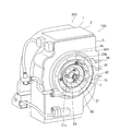
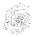
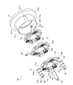
- FIG. 5 It is a typical perspective view which shows the rotary electric machine which concerns on embodiment of this invention. It is a perspective view which shows the state which removed the end cover of the rotary electric machine of FIG. It is a perspective view which shows the state which attached the guide for replacement
- FIG. 8 is a cross-sectional side view similar to FIG. 7 showing a process of extracting the brush assembly from the rotating shaft onto the replacement guide. It is a figure which shows the modification of a brush with the cross-sectional side view similar to FIG. It is a cross-sectional side view which shows a state when arrange
- rotating electrical machine 100 according to an embodiment of the present invention will be described with reference to the accompanying drawings.
- rotating electric machine 100 will be described as being incorporated in a hybrid transaxle for operating a hybrid vehicle.
- the rotating electrical machine 100 constitutes a double rotor type rotating electrical machine to which three-phase AC power is applied.
- the rotating electrical machine 100 constitutes a part of the hybrid transaxle 200.
- the rotating electrical machine 100 includes a rotating electrical machine housing 1 including a metal motor housing portion 2, a metal motor cover 3, and a metal end cover 4.
- the rotating electrical machine housing 1 also serves as a housing for the transaxle 200.
- the motor cover 3 constitutes a housing
- the end cover 4 constitutes a cover.
- the motor housing part 2 has a shape in which a rectangular parallelepiped box is connected to the top and bottom of a cylinder, and is open at one end in the cylinder axis direction.
- the motor cover 3 is attached to the motor housing portion 2 so as to close the opening at the end.
- a part of the motor cover 3 has a cylindrical shape that opens at the end opening 3b1.
- the end cover 4 is attached to the motor cover 3 using bolts 4d so as to close the end opening 3b1 of the motor cover 3.
- an external terminal 34 for electrically connecting the rotating electrical machine 100 to an external electric device is provided outside the motor cover 3, an external terminal 34 for electrically connecting the rotating electrical machine 100 to an external electric device is provided.
- the motor housing portion 2, the motor cover 3, and the end cover 4 define a motor housing space 5 in the interior that they surround.
- the motor cover 3 includes a plate-like flange portion 3a, a substantially cylindrical small-diameter cylindrical portion 3c, and a substantially cylindrical large-diameter cylindrical portion 3b.
- the flange portion 3 a is fixed to the opening at the end of the motor housing portion 2 and extends in a direction perpendicular to the cylindrical axis of the motor housing portion 2.
- the flange portion 3a has a circular opening 3a1 near the center.
- the small diameter cylindrical portion 3c extends in the motor housing space 5 perpendicularly to the flange portion 3a and continuously from the opening 3a1.
- the large-diameter cylindrical portion 3b extends from the flange portion 3a on the side opposite to the small-diameter cylindrical portion 3c and from a position radially outside the opening 3a1.
- the end of the large-diameter cylindrical portion 3 b forms an end opening 3 b 1 that is closed by the end cover 4.
- the rotating electrical machine 100 includes a metal rotating shaft 7 and a metal first rotor support member 8.
- the rotating shaft 7 extends through the slip ring mechanism housing space 6 to the motor housing space 5 along the direction of the cylindrical axis of the large diameter cylindrical portion 3b and the small diameter cylindrical portion 3c.
- the first rotor support member 8 is connected to an end portion 7a of the rotary shaft 7 on the side opposite to the end cover 4 so as to be integrally rotatable.
- the first rotor support member 8 is disposed coaxially with the rotation shaft 7.
- a female screw hole 7c extending along the axial direction is formed at the center of the tip of the end 7b of the rotary shaft 7 on the end cover 4 side.
- the gap between the inner peripheral surface of the end of the small diameter cylindrical portion 3c opposite to the large diameter cylindrical portion 3b and the outer peripheral surface of the rotary shaft 7 is hermetically sealed by an annular seal member 9. Furthermore, in the vicinity of the end cover 4 side of the seal member 9 in the slip ring mechanism housing space 6, an annular partition wall 3c1 protruding from the small diameter cylindrical portion 3c toward the rotating shaft 7 is integrally formed with the small diameter cylindrical portion 3c. Yes.
- the partition wall 3c1 is formed with three female screw holes 3c2 arranged at equal intervals along the circumferential direction. Each female screw hole 3c2 passes through the partition wall 3c1 along the axial direction of the rotary shaft 7.
- the female screw hole 3c2 constitutes a screw fastening hole.
- the first rotor support member 8 includes a cylindrical input shaft portion 8 a that protrudes on the opposite side of the rotation shaft 7, and a cylindrical rotor support that extends so as to surround the small-diameter cylindrical portion 3 c from the outside in the motor housing space 5.
- the part 8b is integrally included.
- the input shaft portion 8a is configured such that the rotational driving force of the driving device is transmitted by fitting and inserting a rotating shaft of a driving device such as an engine inside the cylinder.
- the rotor support portion 8b supports the cylindrical first rotor core 51a of the first rotor 51 provided on the outer peripheral side thereof, and rotates integrally with the first rotor core 51a.
- the first rotor 51 includes a three-phase winding 51b arranged along the circumferential direction inside the first rotor core 51a.
- the first rotor 51 constitutes a rotor.
- the rotor support portion 8b is rotatably supported by the flange portion 3a of the motor cover 3 via an inner ball bearing 10 provided on the outer peripheral side thereof.
- the inner ball bearing 10 constitutes a bearing.
- a cylindrical second rotor core 52a of the second rotor 52 is provided so as to surround the outer periphery of the first rotor core 51a.
- the 2nd rotor 52 has the permanent magnet 52b arrange
- the second rotor core 52a is sandwiched between second rotor support members 11a and 11b provided on both sides in the cylindrical axis direction.
- the second rotor support member 11b has a cylindrical shape.
- the second rotor support member 11b is disposed on the flange portion 3a side of the motor cover 3 with respect to the second rotor core 52a, and is connected to the second rotor core 52a so as to be integrally rotatable. And the 2nd rotor support member 11b is rotatably supported by the flange part 3a via the outer side ball bearing 12 provided in the outer peripheral side.
- the second rotor support member 11a has a bottomed cylindrical shape.
- the second rotor support member 11a is disposed on the opposite side of the flange portion 3a with respect to the second rotor core 52a, and is formed on the second rotor core 52a so as to be rotatable integrally with the second rotor core 52a together with the second rotor support member 11b. It is connected.
- the 2nd rotor support member 11a is rotatably supported by the outer peripheral surface of the input shaft part 8a via the ball bearing 13 provided in the inner peripheral side.
- the second rotor support member 11a includes a cylindrical output shaft portion 11a1 extending in the same direction as the input shaft portion 8a at the center of the bottom portion by integral molding.
- the output shaft portion 11a1 is disposed coaxially with the input shaft portion 8a and the rotating shaft 7.
- the second rotor 52 and the second rotor support members 11a and 11b can be integrally rotated relative to the input shaft portion 8a, that is, relative to the rotating shaft 7 and the first rotor 51.
- the output shaft portion 11a1 of the second rotor support member 11a can output a rotational driving force to a vehicle drive mechanism or the like that engages with gear teeth formed on the outer peripheral surface of the output shaft portion 11a1.
- a cylindrical stator core 53a of the stator 53 is provided so as to surround the outer periphery of the second rotor core 52a.
- the stator core 53 a is fixed to the motor housing portion 2.
- the stator 53 includes a three-phase winding 53b disposed along the circumferential direction inside the stator core 53a.
- the stator 53 constitutes a stator. Therefore, the rotating electrical machine 100 constitutes a double rotor type rotating electrical machine including the first rotor 51, the second rotor 52, and the stator 53.
- an inner arc-shaped groove 4a1 and an outer arc-shaped groove 4b1 that open into the slip ring mechanism accommodating space 6 are formed on the inner surface 4c of the end cover 4.
- the inner arcuate groove 4a1 and the outer arcuate groove 4b1 extend so as to surround the periphery of the rotary shaft 7 with a space therebetween.
- the outer arcuate groove 4b1 extends so as to surround the inner arcuate groove 4a1 from the outside in the radial direction of the rotating shaft 7.
- the inner arcuate groove 4 a 1 communicates with the inlet 4 a formed on the outer side of the end cover 4, and the outer arcuate groove 4 b 1 communicates with the outlet port 4 b formed on the outer side of the end cover 4.
- the introduction port 4a communicates with a blower (not shown) and is configured to supply air as a cooling fluid into the slip ring mechanism housing space 6.
- the outlet 4 b is configured so that air in the slip ring mechanism accommodation space 6 can be released to the outside of the slip ring mechanism accommodation space 6.
- a rotation sensor 14 that detects the number of rotations of the rotating shaft 7 is embedded so as to surround the rotating shaft 7 on the radially inner side of the inner arc-shaped groove 4 a 1.
- the rotation sensor 14 includes a cylindrical sensor rotor 14a attached so as to rotate integrally near the tip of the end portion 7b of the rotary shaft 7 on the end cover 4 side, and a bolt or the like on the inner surface 4c of the end cover 4. And a cylindrical sensor stator 14b fixed at the same position. In the rotation sensor 14, when the sensor stator 14b detects the rotation of the sensor rotor 14a, the number of rotations of the sensor rotor 14a is detected.
- a resolver, an optical or magnetic encoder, or the like can be used as the rotation sensor 14.
- the brush assembly 20 is provided so as to surround the outer peripheral surface of the rotating shaft 7.
- the brush assembly 20 is configured to be attached to the slip ring 31.
- the brush assembly 20 and the slip ring 31 constitute a slip ring mechanism that electrically connects the first rotor 51 of the rotating electrical machine 100 and an electrical device outside the rotating electrical machine 100.
- the brush assembly 20 includes a substantially cylindrical assembly cover 21.
- the assembly cover 21 extends from the portion between the inner arcuate groove 4a1 and the outer arcuate groove 4b1 on the inner surface 4c of the end cover 4 along the rotating shaft 7 so as to surround the outer peripheral surface of the rotating shaft 7. ing.
- the assembly cover 21 includes a large-diameter portion 21b and a small-diameter portion 21a that extend so as to follow the inner peripheral surfaces of the large-diameter cylindrical portion 3b and the small-diameter cylindrical portion 3c, respectively.
- the assembly cover 21 forms a reciprocating flow path along the axial direction of the rotating shaft 7 in the slip ring mechanism accommodating space 6.
- the reciprocating flow path is reversed from the inside arcuate groove 4a1 through the space between the rotary shaft 7 and the assembly cover 21 and then out of the assembly cover 21, and the small diameter cylindrical portion 3c and the large diameter cylindrical portion 3b This is a flow path that passes between the assembly cover 21 and the outer arcuate groove 4b1.
- three annular slip rings 31 formed of a conductive material are provided so as to surround the outer periphery of the rotating shaft 7.
- the three slip rings 31 are arranged in a row at intervals from each other along the axial direction of the rotary shaft 7.
- the three slip rings 31 are embedded in a cylindrical insulating member 32 that is formed so as to cover the outer peripheral surface of the rotary shaft 7 and is made of a material having electrical insulation properties such as resin.
- the three slip rings 31 are electrically insulated from each other by an insulating member 32.
- the three slip rings 31 have their outer peripheral surfaces exposed from the insulating member 32.
- slip ring bus bars 33 extending along the axial direction of the rotating shaft 7 are embedded in the insulating member 32.
- the slip ring bus bars 33 are insulated from each other by an insulating member 32.
- Each slip ring bus bar 33 electrically connects each slip ring 31 to different windings 51 b of the first rotor 51.
- the outer diameter of each of the slip ring 31 and the insulating member 32 is larger than the outer diameter of the end portion 7 b of the rotating shaft 7 located on the end cover 4 side than the insulating member 32.
- the brush assembly 20 includes a plurality of brushes 22 that are in contact with the exposed outer peripheral surfaces of the slip rings 31 and have conductivity.
- Three brushes 22 are arranged for each slip ring 31.
- the brush assembly 20 includes three annular plate-like base ring plates 23 formed of a conductive material such as metal, and three brush holders 24 fixed on the surface 23 a of each base ring plate 23.
- Three winding springs 25 and three electrical connections 26 are included.
- Each brush holder 24 is made of a conductive material such as metal, and holds each brush 22 slidably inside.
- Each winding spring 25 presses each brush 22 toward the slip ring 31.
- Each electrical connection portion 26 is constituted by an electric wire and a terminal, and electrically connects each brush 22 to the base ring plate 23. From each base ring plate 23, an integrally molded bus bar 23b protrudes.
- the bus bar 23b is configured to be electrically connected to an external electrical device of the rotating electrical machine 100.
- the base ring plate 23 constitutes a
- the brush assembly 20 includes three cylindrical bracket members 27 that hold the three base ring plates 23 at predetermined intervals along the cylindrical axis direction of the assembly cover 21.
- the bracket member 27 is formed from a material having electrical insulation properties such as resin.
- the bracket member 27 constitutes a holding portion.
- the cylindrical outer peripheral surface of the bracket member 27 has a shape that matches the first outer peripheral surface 27a having a semi-oval cross section and the inner peripheral surface of the small diameter portion 21a of the assembly cover 21, and has an arc-shaped cross section.
- the second outer peripheral surface 27b Three fitting grooves 27a1 extending in the circumferential direction and arranged in the axial direction of the bracket member 27 are formed at equal intervals on the first outer circumferential surface 27a.
- the collar 28 which penetrates the bracket member 27 along the axial direction is embedded in the bracket member 27 over both axial end surfaces 27c and 27d.
- the collar 28 is a metal cylinder in which an axial through hole 28a is formed.
- the collar 28 slightly protrudes from both end faces 27c and 27d.
- the through hole 28a constitutes an insertion hole.
- Each base ring plate 23 is formed with three recesses 23c that are recessed radially inward from the outer periphery thereof.
- the three recesses 23 c are arranged at equal intervals along the circumferential direction of the base ring plate 23.
- Each recess 23c has a shape that matches the fitting groove 27a1 when fitted into the fitting groove 27a1 of the bracket member 27. Therefore, the three base ring plates 23 are held by the bracket member 27 at an equal interval by fitting the recesses 23c of the base ring plates 23 into the fitting grooves 27a1 of the bracket member 27, respectively. .
- the three brush holders 24 are positioned so as to overlap each other between the base ring plates 23, that is, between the three base ring plates 23.
- the brush holders 24 are arranged in a straight line.
- each brush holder 24 facing the base ring plate 23 is formed with a first fixing bar insertion hole 24a penetrating through this portion.
- An insertion hole (not shown) is also formed through the base ring plate 23 at a position facing the first fixing bar insertion hole 24a.
- Each brush 22 also has a second fixing bar insertion hole 22a formed therethrough.
- each brush 22 is aligned with the first fixing bar insertion hole 24a and the insertion hole of the base ring plate 23, the three rod-shaped fixing bars 29
- the base ring plate 23 can be inserted into the insertion holes of the brush 22 and the brush holder 24 arranged in a row.
- each brush 22 is held so as not to protrude inside the through opening 23 d of the base ring plate 23.
- each fixing rib 21c is formed with a through hole 21c1 penetrating therethrough.
- the three through holes 21c1 are positioned so as to align with the through holes 28a of the collars 28 of the three bracket members 27 fitted to the base ring plate 23.
- the three female screw holes 3c2 formed in the partition wall 3c1 of the motor cover 3 are also aligned with the through holes 28a of the collars 28 of the three bracket members 27 fitted to the base ring plate 23. It is in the position to do.
- the brush assembly 20 as described above is arranged and fixed as described below in the slip ring mechanism housing space 6 of the rotating electrical machine 100 with the end cover 4 removed.
- the three base ring plates 23 are fitted with the recesses 23c in the fitting grooves 27a1 of the bracket member 27, respectively, and the three base rings are spaced at equal intervals.
- the plate 23 is held by a bracket member 27.
- the three base ring plates 23 are arranged so that the three bus bars 23b are positioned radially.
- each base ring plate 23 and the second outer peripheral surface 27b of each bracket member 27 are aligned with the inner peripheral surface of the small diameter portion 21a, whereby the three base ring plates 23 and the three bracket members 27 are aligned. However, it is held in the radial direction within the small diameter portion 21a without causing rattling.
- a fixing bar 29 is provided for each of the brushes 22 and the brush holders 24 arranged in a row in the three base ring plates 23, and the first fixing bar insertion hole 24 a of the brush holder 24 and the second fixing bar insertion hole 22 a of the brush 22. And it is inserted through an insertion hole (not shown) of the base ring plate 23. Thereby, each brush 22 is held so as not to protrude inside the through opening 23 d of the base ring plate 23.
- the assembly cover 21 to which the base ring plate 23 and the bracket member 27 are assembled has an end opening so that the rotating shaft 7 and the slip ring 31 are passed through the through opening 23d of each base ring plate 23 from the small diameter portion 21a side. It is inserted into the slip ring mechanism accommodating space 6 through the portion 3b1. At this time, the assembly cover 21 is rotated so that the through holes 28a of the collars 28 of the bracket members 27 and the female screw holes 3c2 of the partition walls 3c1 of the motor cover 3 are aligned.
- bolts 30 as screw fastening members are screwed into the respective female screw holes 3c2 from the through holes 21c1 of the respective fixing ribs 21c through the through holes 28a of the respective collars 28, whereby the assembly cover 21 and the bracket member 27, that is, The brush assembly 20 is fixed to the motor cover 3.
- the fixing bar 29 is removed, whereby the brushes 22 that receive the urging force of the winding spring 25 are pressed against the slip rings 31 respectively. Furthermore, referring also to FIG. 2, three electric wire cables 35 extending from the external terminal 34 to the inside of the large-diameter cylindrical portion 3b of the motor cover 3 are connected to the three bus bars 23b. As a result, the arrangement and fixing of the brush assembly 20 in the slip ring mechanism accommodating space 6 are completed. As described above, the brush assembly 20 extends radially inward of the first rotor 51, the second rotor 22, and the ball bearings 10 and 12, and is opposite to the input shaft portion 8a and the output shaft portion 11a1 with respect to the rotating shaft 7. Placed on the side.
- the end cover 4 is attached to the motor cover 3 using the bolts 4d.
- the sensor stator 14 b of the rotation sensor 14 fixed to the end cover 4 is positioned so as to surround the sensor rotor 14 a fixed to the rotation shaft 7.
- the outer diameter of the sensor rotor 14a is set to be equal to or smaller than the outer diameter of the slip ring 31 and more preferably equal to or smaller than the outer diameter of the insulating member 32 so as not to hinder the attachment of the brush assembly 20.
- a terminal 14 c extending from the sensor stator 14 b of the rotation sensor 14 is provided outside the end cover 4. This terminal 14c is electrically connected to a control device (not shown) of the rotating electrical machine 100.
- the rotating electrical machine 100 configured as described above operates as follows. 1 and 7 together, an electric device (not shown) outside the rotating electrical machine 100 is electrically connected to the external terminal 34 of the rotating electrical machine 100.
- an electric device (not shown) outside the rotating electrical machine 100 is electrically connected to the external terminal 34 of the rotating electrical machine 100.
- the supplied current is supplied to the three-phase winding 51 b of the first rotor 51 through the slip ring 31 and the slip ring bus bar 33.
- the rotating magnetic field generated by the current flowing through the three-phase winding 51b acts on the permanent magnet 52b to rotate the second rotor 52, thereby rotating the output shaft portion 11a1.
- the first rotor 51 rotates, and accordingly, an induced current is generated in the three-phase winding 51b of the first rotor 51.
- the generated induced current is supplied to an electrical device outside the rotating electrical machine 100 via the slip ring 31, the brush 22, and the like.
- a three-phase alternating current is supplied to the three-phase winding 53b of the stator 53 from an electric device outside the rotating electrical machine 100, a rotating magnetic field generated by the current flowing through the three-phase winding 53b is applied to the permanent magnet 52b.
- the second rotor 52 is actuated to rotate, whereby the output shaft portion 11a1 is rotationally driven.
- the brush 22 that slides on the slip ring 31 wears, and therefore needs to be replaced.
- the brush 22 is exchanged as described below. Referring to FIGS. 1 and 2 together, the bolt 4 d is removed and the end cover 4 is removed from the motor cover 3. Thereby, the rotating shaft 7 and the sensor rotor 14a of the rotation sensor 14 shown in FIG. Further, each electric cable 35 is removed from the bus bar 23 b of the brush assembly 20 through the end opening 3 b 1 of the motor cover 3.
- a bottomed cylindrical replacement guide 41 is attached to the rotating shaft 7 so as to cover the end 7b of the rotating shaft 7 and the sensor rotor 14a.
- the end opening portion 41 a 1 of the cylindrical portion 41 a of the replacement guide 41 contacts the axial end portion 32 a of the insulating member 32.
- the male screw portion 42a of the fixing bolt 42 is inserted into a through hole 41c formed in the center of the bottom 41b of the replacement guide 41, and the male screw portion 42a is screwed into the female screw hole 7c of the rotating shaft 7 and tightened.
- the replacement guide 41 is fixed to the rotating shaft 7.
- the outer diameter of the sensor rotor 14a is equal to or smaller than the inner diameter of the replacement guide 41.
- the replacement guide 41 constitutes a brush guide member
- the fixing bolt 42 constitutes a guide fastening member.
- annular protrusions 32b1, 32b2, and 32b3 are formed in the circumferential direction at the end portion 32a and the portion between the slip rings 31, respectively.
- the outer diameters of the annular protrusions 32b1, 32b2, and 32b3 are the same as the outer diameter of the slip ring 31. Further, the outer diameter of the replacement guide 41 is equal to the outer diameter of the slip ring 31.
- each brush 22 that is pressed against the slip ring 31 by receiving the urging force of the winding spring 25 also moves in the axial direction of the rotary shaft 7 up to the replacement guide 41.
- each brush 22 is always placed on any one of the slip ring 31, the annular protrusions 32 b 1, 32 b 2, 32 b 3 and the replacement guide 41 having the same outer diameter in the process of movement. While receiving the force, it is possible to move smoothly in the axial direction without causing radial movement and without being caught.
- the rotating electrical machine 100 includes the first rotor 51 including the three-phase winding 51b and the stator 53.
- the rotating electrical machine 100 includes a plurality of slip rings 31 that are arranged in the axial direction on a rotating shaft 7 extending from the first rotor 51 and that can rotate integrally with the rotating shaft 7, a brush assembly 20, and a plurality of slips.
- a motor cover 3 and an end cover 4 that together form a slip ring mechanism housing space 6 for housing the ring 31 and the brush assembly 20 are provided.
- the brush assembly 20 includes a plurality of brushes 22 disposed so as to contact the plurality of slip rings 31, and a plurality of base ring plates 23 disposed for the respective slip rings 31 and holding the brushes 22.
- the motor cover 3 opens at an end opening 3b1 formed on the end 7b side in the extending direction of the rotating shaft 7.
- the end cover 4 is attached to the motor cover 3 so as to close the end opening 3b1.
- the brush assembly 20 can be attached to and detached from the plurality of slip rings 31 through the end opening 3b1.
- the brush assembly 20 includes a bolt 30 on the inner side of the assembly cover 21 that engages with the assembly cover 21 and is screwed into a female screw hole 3 c 2 formed in the motor cover 3 to fix the brush assembly 20 to the motor cover 3.
- the female screw hole 3c2 is positioned on the opposite side of the end opening 3b1 with respect to the brush assembly 20 so that the bolt 30 can be attached and detached through the end opening 3b1.
- the end opening 3b1 has an opening area large enough to attach and detach the brush assembly 20 in the axial direction.
- the brush assembly 20 is inserted into the slip ring mechanism housing space 6 through the end opening 3b1 of the motor cover 3 from which the end cover 4 has been removed, and is set in the rotating shaft 7 and the slip ring 31, and further the end
- the brush assembly 20 can be attached by fastening the bolt 30 from the part opening 3b1 to the female screw hole 3c2 of the assembly cover 21 and the motor cover 3.
- the brush assembly 20 can be removed by removing the bolt 30 through the end opening 3b1 of the motor cover 3 from which the end cover 4 is removed, and further pulling out the brush assembly 20 from the rotating shaft 7. Therefore, the brush assembly 20 can be easily attached / detached, that is, the brush 22 can be easily attached / detached only by accessing the rotating electrical machine 100 from the end opening 3b1.
- the brush assembly 20 includes a cylindrical bracket member 27 that extends in the axial direction of the rotary shaft 7 and holds the plurality of base ring plates 23 at intervals in the axial direction of the rotary shaft 7. Included inside the assembly cover 21.
- the bracket member 27 has a through hole 28 a into which the bolt 30 can be inserted and extends in the axial direction of the rotary shaft 7. Furthermore, the bracket member 27 is detachably provided on the assembly cover 21.
- the bracket member 27 has a fitting groove 27 a 1 that holds the base ring plate 23 by engaging the outer edge of the base ring plate 23.
- the assembly of the bracket member 27 and the base ring plate 23 in which the base ring plate 23 is engaged with the fitting groove 27 a 1 is configured to be inserted into and removed from the assembly cover 21.
- the assembly cover 21 has an opening having an opening area large enough to be inserted and removed in the axial direction at one end of the small diameter portion 21a.
- the assembly includes the bracket member 27 and the base ring plate 23.
- the bracket member 27 can fix the held base ring plate 23 by the bolt 30 being inserted and fastened. Since the bracket member 27 has both functions of holding and fixing the base ring plate 23, the number of parts can be reduced and space can be saved. Further, since the bracket member 27 has a configuration in which the base ring plate 23 is held by being engaged with the bracket member 27, the structure of the base ring plate 23 and the bracket member 27 is simplified, and the mutual assembly is also easy. Become.
- the rotating shaft 7 includes an end portion 7 b having an outer diameter smaller than the outer diameter of the slip ring 31 on the end opening 3 b 1 side than the slip ring 31.
- the end portion 7b is attached with a fixing bolt 42 by a cylindrical replacement guide 41 which is positioned adjacent to the slip ring 31 and surrounds the outer periphery of the end portion 7b and has an outer diameter equivalent to that of the slip ring 31.
- the end 7b has an outer peripheral surface covered with a replacement guide 41 serving as a brush guide member and a female screw hole 7c serving as a fastening hole for fastening a fixing bolt 42 serving as a guide fastening member.
- the step between the outer peripheral surface of the slip ring 31 and the outer peripheral surface of the rotary shaft 7 is eliminated by attaching the replacement guide 41 to the rotary shaft 7. Therefore, when pulling out the brush assembly 20 from the rotating shaft 7, the brush 22 receiving the biasing force to the slip ring 31 by the winding spring 25 can move smoothly without being caught by the step.
- the rotating electrical machine 100 includes a rotation sensor 14 having a sensor rotor 14 a disposed at the end 7 b of the rotating shaft 7 and a sensor stator 14 b disposed at the end cover 4.
- the outer diameter of the sensor rotor 14 a is equal to or smaller than the inner diameter of the replacement guide 41.
- the rotating electrical machine 100 includes an insulating member 32 that is formed around the rotating shaft 7 to support the slip ring 31 and to insulate the slip ring 31 from the other slip rings 31 and the rotating shaft 7.
- the insulating member 32 includes annular protrusions 32b1 and 32b2 protruding between the slip rings 31 and between the slip ring 31 and the replacement guide 41 in the radial direction of the rotary shaft 7 at the same height as the slip ring 31. And 32b3.
- the first rotor 51 includes a cylindrical first rotor core 51a around which the three-phase winding 51b is wound, and the brush assembly 20 freely rotates the first rotor core 51a and the first rotor core 51a.
- the inner ball bearing 10 is supported on the inner side in the radial direction.
- the replacement guide 41 is used only when the brush assembly 20 is detached from the rotating shaft 7, but may be used when the brush assembly 20 is attached to the rotating shaft 7.
- the annular protrusions 32b1, 32b2, and 32b3 are formed on the insulating member 32 so as to surround the periphery of the rotating shaft 7, but the present invention is not limited to this.
- the annular protrusions 32b1, 32b2, and 32b3 may be divided so that the protrusions are present only at locations where the brush 22 passes when the brush assembly 20 is removed.
- the second fixed bar insertion hole 22a of the brush 22 may be modified as shown in FIG.
- the second fixing bar insertion hole 22 a of the brush 22 disposed in the brush holder 24 is a portion on the opposite side of the base ring plate 23 and has an inner peripheral surface aligned with the outer peripheral surface of the fixing bar 29. 22a2.
- the second fixing bar insertion hole 22a includes an enlarged hole portion 22a1 which is a portion adjacent to the fixing hole portion 22a2 on the base ring plate 23 side and has a tapered inner peripheral surface.
- the enlarged hole portion 22a1 has a shape that gradually enlarges the circular cross section of the fixed hole portion 22a2 from the fixed hole portion 22a2 toward the base ring plate 23.
- the circular cross section of the fixing hole portion 22a2 has a long hole cross section in the direction opposite to the rotation shaft 7 and the slip ring 31 and along the sliding direction of the brush 22 in the brush holder 24.
- the portion of the enlarged hole portion 22a1 facing the rotation shaft 7 extends in parallel with the rotation shaft 7, and the portion of the enlarged hole portion 22a1 opposite to the rotation shaft 7 extends from the fixing hole portion 22a2 to the base ring plate 23. It inclines so that it may leave
- the insertion hole of the base ring plate 23 is inserted from the large diameter portion 21b side of the assembly cover 21 as shown in “B: state at the time of removal” in FIG.
- the fixing bar 29 is inserted into the second fixing bar insertion hole 22 a of 23 e and the brush 22. Even when the brush 22 reaches the wear limit, the enlarged hole portion 22a1 of the second fixed bar insertion hole 22a is configured to communicate with the insertion hole 23e. Then, the fixing bar 29 receives the urging force of the winding spring 25 by inserting the fixing bar 29 into the second fixing bar insertion hole 22a and pressing the fixing bar 29 while making contact with the wall surface of the enlarged hole portion 22a1.
- the brush 22 is moved away from the slip ring 31. Further, when the fixing bar 29 is passed through the fixing hole portion 22 a 2 and the first fixing bar insertion hole 24 a of the brush holder 24, the brush 22 is held without protruding from the base ring plate 23 and the brush holder 24. The other brushes 22 are also held in a state where they do not protrude from the base ring plate 23 and the brush holder 24 by passing the fixing bar 29 through the second fixing bar insertion hole 22a. Therefore, the brush 22 does not interfere with the slip ring 31 or the like when the brush assembly 20 is detached from the rotating shaft 7.
- the replacement guide 41 may be used when the above-described brush assembly 20 is disposed and removed. Thereby, damage to sensor rotor 14a by contact with the appendage of brush assembly 20 can be prevented.
- the first rotor 51 and the stator 53 are provided with windings, and the second rotor 52 is provided with permanent magnets. It is not limited to this.
- a slip ring may be provided on at least one of the rotating shafts of the two rotors.
- the rotating electrical machine 100 according to the embodiment is a double rotor type rotating electrical machine including the first rotor 51, the second rotor 52, and the stator 53, but is not limited thereto.
- the rotating electrical machine 100 may be a double rotor type motor including only the two rotors including the first rotor 51 and the second rotor 52 without including the stator 53. Alternatively, there may be one rotor.
- the rotating electrical machine may have a structure in which a slip ring is provided on a rotating shaft extending from the rotor.
- the cooling fluid may be a gas other than air. It may be liquid.
- the liquid used as the cooling fluid is more preferably a liquid having no conductivity.
Landscapes
- Engineering & Computer Science (AREA)
- Power Engineering (AREA)
- Motor Or Generator Frames (AREA)
- Motor Or Generator Current Collectors (AREA)
Abstract
回転電機(100)のブラシアセンブリ(20)は、モータカバー(3)の端部開口部(3b1)を通ってスリップリング(31)に着脱可能である。ブラシアセンブリ(20)は、ブラシアセンブリ(20)をモータカバー(3)に固定するボルト(30)をアセンブリカバー(21)の内側に有する。ボルト(30)が螺合するモータカバー(3)の雌ねじ穴(3c2)は、端部開口部(3b1)を介してボルト(30)の着脱が可能であるように、ブラシアセンブリ(20)に対して端部開口部(3b1)と反対側に位置する。
Description
本発明は、回転電機に係り、特にスリップリングを備える回転電機に関する。
回転電機では、回転軸と共に回転するスリップリングに、外部のインバータ、バッテリ等の電気機器と電気的に接続されたブラシを接触させることによって、回転電機と電気機器との間で電力の需給が行われる。
例えば特許文献1には、スリップリングと、ブラシと、ブラシを収容するブラシホルダと、ブラシホルダを支持するブラシホルダ支えとがコレクタカバー内に収容された回転電機が記載されている。コレクタカバー内では、軸方向に沿って回転軸に設けられた3つのスリップリングそれぞれに接触させるようにして、ブラシが配置されている。さらに、コレクタカバー内には、軸方向に沿って3つの仕切りがスリップリングに対向するように突出している。各仕切りには、絶縁板で製作された環状の絶縁支え板が取り付けられている。各絶縁支え板には、ブラシホルダ支えが取り付けられている。
例えば特許文献1には、スリップリングと、ブラシと、ブラシを収容するブラシホルダと、ブラシホルダを支持するブラシホルダ支えとがコレクタカバー内に収容された回転電機が記載されている。コレクタカバー内では、軸方向に沿って回転軸に設けられた3つのスリップリングそれぞれに接触させるようにして、ブラシが配置されている。さらに、コレクタカバー内には、軸方向に沿って3つの仕切りがスリップリングに対向するように突出している。各仕切りには、絶縁板で製作された環状の絶縁支え板が取り付けられている。各絶縁支え板には、ブラシホルダ支えが取り付けられている。
ブラシは、回転するスリップリングに対して押圧された状態でスリップリング上を摺動する。このため、ブラシは摩耗を生じ、時間の経過と共にブラシの交換が必要となる。回転電機は、車両に搭載されるトランスアスクルに組み込まれる場合がある。このような回転電機の場合、車両内の限られた狭いスペース内でブラシの交換作業を行う必要がある。しかしながら、特許文献1の回転電機のようにブラシがコレクタカバー内に収容されて複数の部材を用いて保持されている構成では、ブラシの交換作業が非常に困難なものになるという問題がある。
本発明は上記のような問題を解決するためになされたものであり、ブラシの交換を容易にする回転電機を提供することを目的とする。
上記の課題を解決するために、本発明に係る回転電機は、巻線を含む回転子と固定子とを備えた回転電機であって、回転子から延びる回転軸に軸方向に並んで配設され、回転軸と一体に回転可能である複数のスリップリングと、複数のスリップリングに接触するように配設される複数のブラシ、複数のスリップリングのそれぞれに対して配設され且つブラシを保持する複数のブラシベース、及び複数のブラシベースを内側で保持する筒状のアセンブリカバーを含むブラシアセンブリと、複数のスリップリング及びブラシアセンブリを収容する収容空間を共に形成するハウジング及びカバーとを備え、ハウジングは、上記回転軸の延びる方向に形成された開口部で開口し、カバーは、上記開口部を塞ぐようにハウジングに取り付けられ、ブラシアセンブリは、上記開口部を通って複数のスリップリングに着脱可能であり、ブラシアセンブリは、アセンブリカバーに係合し且つハウジングに形成されたねじ締結穴に螺合してブラシアセンブリをハウジングに固定するねじ締結部材を、アセンブリカバーの内側に有し、ねじ締結穴は、上記開口部を介してねじ締結部材の着脱が可能であるように、ブラシアセンブリに対して上記開口部と反対側に位置する。
本発明に係る回転電機によれば、ブラシの交換を容易にすることが可能になる。
以下、本発明の実施の形態に係る回転電機100について、添付図面に基づいて説明する。なお、以下の実施の形態では、回転電機100は、ハイブリッド自動車を稼働させるためのハイブリッドトランスアクスルに組み込まれるものとして説明する。
図1及び図7に示すように、回転電機100は、三相交流電力が印加されるダブルロータ型の回転電機を構成している。そして、回転電機100は、ハイブリッドトランスアクスル200の一部を構成している。
回転電機100は、金属製モータハウジング部2と金属製モータカバー3と金属製エンドカバー4とによって構成される回転電機ハウジング1を備えている。回転電機ハウジング1は、トランスアクスル200のハウジングを兼ねている。ここで、モータカバー3はハウジングを構成し、エンドカバー4はカバーを構成している。
回転電機100は、金属製モータハウジング部2と金属製モータカバー3と金属製エンドカバー4とによって構成される回転電機ハウジング1を備えている。回転電機ハウジング1は、トランスアクスル200のハウジングを兼ねている。ここで、モータカバー3はハウジングを構成し、エンドカバー4はカバーを構成している。
モータハウジング部2は、円筒の上下に直方体状の箱を連結した形状を有しおり、円筒軸方向の一方の端部で開放している。モータカバー3は、上記端部の開口部を塞ぐようにモータハウジング部2に取り付けられる。モータカバー3の一部は、端部開口部3b1で開口する筒状の形状を有している。エンドカバー4は、モータカバー3の端部開口部3b1を塞ぐように、モータカバー3にボルト4dを用いて取り付けられる。モータカバー3の外側には、外部の電気機器に回転電機100を電気的に接続するための外部端子34が設けられている。
モータハウジング部2、モータカバー3及びエンドカバー4は、これらが囲む内部にモータ収容空間5を区画形成している。
モータハウジング部2、モータカバー3及びエンドカバー4は、これらが囲む内部にモータ収容空間5を区画形成している。
モータカバー3は、板状のフランジ部3aと、略円筒状の小径筒部3cと、略円筒状の大径筒部3bとを備えている。
フランジ部3aは、モータハウジング部2の端部の開口部に固定されてモータハウジング部2の円筒軸に垂直な方向に延在する。フランジ部3aは、中心付近に円状の開口部3a1を有する。小径筒部3cは、モータ収容空間5内でフランジ部3aに垂直に且つ開口部3a1から連続して延在する。大径筒部3bは、フランジ部3aから小径筒部3cと反対側に且つ開口部3a1よりも径方向外側の位置から延在する。大径筒部3bの端部は、エンドカバー4によって塞がれる端部開口部3b1を形成している。
これにより、モータ収容空間5内において、大径筒部3b及び小径筒部3cの内側には、大径筒部3bから小径筒部3cにわたって内径が段差状に減少するスリップリング機構収容空間6が区画形成される。
フランジ部3aは、モータハウジング部2の端部の開口部に固定されてモータハウジング部2の円筒軸に垂直な方向に延在する。フランジ部3aは、中心付近に円状の開口部3a1を有する。小径筒部3cは、モータ収容空間5内でフランジ部3aに垂直に且つ開口部3a1から連続して延在する。大径筒部3bは、フランジ部3aから小径筒部3cと反対側に且つ開口部3a1よりも径方向外側の位置から延在する。大径筒部3bの端部は、エンドカバー4によって塞がれる端部開口部3b1を形成している。
これにより、モータ収容空間5内において、大径筒部3b及び小径筒部3cの内側には、大径筒部3bから小径筒部3cにわたって内径が段差状に減少するスリップリング機構収容空間6が区画形成される。
さらに、回転電機100は、金属製の回転軸7と金属製の第一ロータ支持部材8とを備えている。回転軸7は、スリップリング機構収容空間6内を大径筒部3b及び小径筒部3cの円筒軸方向に沿って通りモータ収容空間5にまで延在する。第一ロータ支持部材8は、回転軸7におけるエンドカバー4と反対側の端部7aに一体に回転可能であるように連結されている。第一ロータ支持部材8は、回転軸7と同軸上に配置されている。
回転軸7のエンドカバー4側の端部7bの先端中央には、軸方向に沿って延在する雌ねじ穴7cが形成されている。
回転軸7のエンドカバー4側の端部7bの先端中央には、軸方向に沿って延在する雌ねじ穴7cが形成されている。
小径筒部3cにおける大径筒部3bと反対側の端部の内周面と回転軸7の外周面との間の間隙は、環状のシール部材9によって気密に封止されている。
さらに、スリップリング機構収容空間6内におけるシール部材9のエンドカバー4側の近傍では、小径筒部3cから回転軸7に向かって突出する環状の隔壁3c1が、小径筒部3cに一体成形されている。隔壁3c1には、周方向に沿って等間隔に配置された3つの雌ねじ穴3c2が形成されている。各雌ねじ穴3c2は、回転軸7の軸方向に沿って隔壁3c1を貫通している。ここで、雌ねじ穴3c2は、ねじ締結穴を構成している。
さらに、スリップリング機構収容空間6内におけるシール部材9のエンドカバー4側の近傍では、小径筒部3cから回転軸7に向かって突出する環状の隔壁3c1が、小径筒部3cに一体成形されている。隔壁3c1には、周方向に沿って等間隔に配置された3つの雌ねじ穴3c2が形成されている。各雌ねじ穴3c2は、回転軸7の軸方向に沿って隔壁3c1を貫通している。ここで、雌ねじ穴3c2は、ねじ締結穴を構成している。
第一ロータ支持部材8は、回転軸7と反対側に突出する円筒状の入力軸部8aと、モータ収容空間5内で小径筒部3cを外側から囲むように延在する円筒状のロータ支持部8bとを、一体に含んでいる。入力軸部8aは、その円筒の内側にエンジン等の駆動装置の回転軸が嵌合挿入されることで駆動装置の回転駆動力が伝達されるように構成されている。ロータ支持部8bは、その外周側に設けられる第一ロータ51の円筒状の第一ロータコア51aを支持し第一ロータコア51aと一体に回転する。なお、第一ロータ51は、第一ロータコア51aの内部に、周方向に沿って配置された三相巻線51bを含んでいる。ここで、第一ロータ51は回転子を構成している。
ロータ支持部8bは、その外周側に設けられた内側ボールベアリング10を介してモータカバー3のフランジ部3aによって回転自在に支持されている。ここで、内側ボールベアリング10は軸受を構成している。
上述のような構成を有する回転軸7、第一ロータ支持部材8及び第一ロータ51は、回転軸7の回転中心軸を中心として、回転電機ハウジング1に対して、一体に回転することができる。
上述のような構成を有する回転軸7、第一ロータ支持部材8及び第一ロータ51は、回転軸7の回転中心軸を中心として、回転電機ハウジング1に対して、一体に回転することができる。
さらに、モータ収容空間5内では、第一ロータコア51aの外周を囲むようにして第二ロータ52の円筒状の第二ロータコア52aが設けられている。第二ロータ52は、第二ロータコア52aの内部に、周方向に沿って配置された永久磁石52bを有している。
第二ロータコア52aは、その円筒軸方向の両側に設けられた第二ロータ支持部材11a及び11bによって挟持されている。
第二ロータ支持部材11bは、筒状の形状を有している。第二ロータ支持部材11bは、第二ロータコア52aに対してモータカバー3のフランジ部3a側に配置され、第二ロータコア52aに一体に回転可能であるように連結されている。そして、第二ロータ支持部材11bは、その外周側に設けられた外側ボールベアリング12を介してフランジ部3aによって回転自在に支持されている。
第二ロータコア52aは、その円筒軸方向の両側に設けられた第二ロータ支持部材11a及び11bによって挟持されている。
第二ロータ支持部材11bは、筒状の形状を有している。第二ロータ支持部材11bは、第二ロータコア52aに対してモータカバー3のフランジ部3a側に配置され、第二ロータコア52aに一体に回転可能であるように連結されている。そして、第二ロータ支持部材11bは、その外周側に設けられた外側ボールベアリング12を介してフランジ部3aによって回転自在に支持されている。
第二ロータ支持部材11aは、有底円筒状の形状を有している。第二ロータ支持部材11aは、第二ロータコア52aに対してフランジ部3aと反対側に配置され、第二ロータ支持部材11bと共に第二ロータコア52aと一体に回転可能であるように第二ロータコア52aに連結されている。そして、第二ロータ支持部材11aは、その内周側に設けられたボールベアリング13を介して、入力軸部8aの外周面によって回転自在に支持されている。さらに、第二ロータ支持部材11aは、その底部の中心に、入力軸部8aと同方向に延びる円筒状の出力軸部11a1を一体成形によって含んでいる。出力軸部11a1は、入力軸部8a及び回転軸7と同軸に配置されている。
よって、第二ロータ52と第二ロータ支持部材11a及び11bとは一体となって、入力軸部8aに対して、つまり、回転軸7及び第一ロータ51に対して相対回転することができる。そして、第二ロータ支持部材11aの出力軸部11a1は、出力軸部11a1の外周面に形成されたギヤ歯に係合する車両の駆動機構等に、回転駆動力を出力することができる。
また、モータ収容空間5内では、第二ロータコア52aの外周を囲むようにしてステータ53の円筒状のステータコア53aが設けられている。ステータコア53aは、モータハウジング部2に固定されている。ステータ53は、ステータコア53aの内部に、周方向に沿って配置された三相巻線53bを含んでいる。ここで、ステータ53は固定子を構成している。
従って、回転電機100は、第一ロータ51、第二ロータ52及びステータ53を備えたダブルロータ型の回転電機を構成している。
従って、回転電機100は、第一ロータ51、第二ロータ52及びステータ53を備えたダブルロータ型の回転電機を構成している。
エンドカバー4の内側表面4c上には、スリップリング機構収容空間6内に開口する内側円弧状溝4a1及び外側円弧状溝4b1が、形成されている。内側円弧状溝4a1及び外側円弧状溝4b1は、互いに間隔をあけて回転軸7の周囲を囲むようにして延在している。外側円弧状溝4b1は、回転軸7の径方向で内側円弧状溝4a1を外側から囲むように延在している。内側円弧状溝4a1は、エンドカバー4の外側に形成された導入口4aに連通し、外側円弧状溝4b1は、エンドカバー4の外側に形成された導出口4bに連通している。導入口4aは、図示しない送風装置に連通し、冷却用流体としての空気をスリップリング機構収容空間6内に供給できるように構成されている。導出口4bは、スリップリング機構収容空間6内の空気をスリップリング機構収容空間6の外部に放出できるように構成されている。
さらに、エンドカバー4の内側表面4c上において、内側円弧状溝4a1の径方向内側には、回転軸7の回転数を検知する回転センサ14が、回転軸7を囲むように埋め込まれている。
回転センサ14は、エンドカバー4側の回転軸7の端部7bの先端付近に一体に回転するように取り付けられた円筒状のセンサ回転子14aと、エンドカバー4の内側表面4c上にボルト等で固定された円筒状のセンサ固定子14bとを含む。回転センサ14では、センサ回転子14aの回転をセンサ固定子14bが検出することによって、センサ回転子14aの回転数が検知される。回転センサ14としては、レゾルバ、光学式または磁気式のエンコーダ等を使用することができる。
回転センサ14は、エンドカバー4側の回転軸7の端部7bの先端付近に一体に回転するように取り付けられた円筒状のセンサ回転子14aと、エンドカバー4の内側表面4c上にボルト等で固定された円筒状のセンサ固定子14bとを含む。回転センサ14では、センサ回転子14aの回転をセンサ固定子14bが検出することによって、センサ回転子14aの回転数が検知される。回転センサ14としては、レゾルバ、光学式または磁気式のエンコーダ等を使用することができる。
スリップリング機構収容空間6内では、ブラシアセンブリ20が、回転軸7の外周面を囲むように設けられている。ブラシアセンブリ20は、スリップリング31に取り付けられるように構成されている。そして、ブラシアセンブリ20及びスリップリング31は、回転電機100の第一ロータ51と回転電機100の外部の電気機器とを電気的に接続するスリップリング機構を構成する。
ブラシアセンブリ20は、略円筒状のアセンブリカバー21を含む。アセンブリカバー21は、エンドカバー4の内側表面4c上における内側円弧状溝4a1と外側円弧状溝4b1との間の部位から回転軸7に沿って、回転軸7の外周面を囲むようにして延在している。アセンブリカバー21は、大径筒部3b及び小径筒部3cの内周面にそれぞれならうように延在する大径部21b及び小径部21aを含む。
ブラシアセンブリ20は、略円筒状のアセンブリカバー21を含む。アセンブリカバー21は、エンドカバー4の内側表面4c上における内側円弧状溝4a1と外側円弧状溝4b1との間の部位から回転軸7に沿って、回転軸7の外周面を囲むようにして延在している。アセンブリカバー21は、大径筒部3b及び小径筒部3cの内周面にそれぞれならうように延在する大径部21b及び小径部21aを含む。
さらに、アセンブリカバー21は、スリップリング機構収容空間6内で回転軸7の軸方向に沿った往復流路を形成する。この往復流路は、内側円弧状溝4a1から回転軸7とアセンブリカバー21との間を通ってアセンブリカバー21の外に出た後に向きを反転し、小径筒部3c及び大径筒部3bとアセンブリカバー21との間を通って外側円弧状溝4b1に至る流路である。
アセンブリカバー21の小径部21aの内周側には、導電性を有する材料から形成された3つの輪状のスリップリング31が、回転軸7の外周を囲むように設けられている。3つのスリップリング31は、回転軸7の軸方向に沿って互いに間隔をあけて一列に配置されている。3つのスリップリング31は、回転軸7の外周面を覆うように形成され且つ樹脂等の電気的な絶縁性を有する材料からなる円筒状の絶縁部材32に、埋め込まれている。3つのスリップリング31は、絶縁部材32によって互いに電気的に絶縁されている。3つのスリップリング31は、それぞれの外周面を絶縁部材32から露出させている。
さらに、絶縁部材32の内部には、回転軸7の軸方向に沿って延在する3つのスリップリング用バスバー33が埋め込まれている。各スリップリング用バスバー33は、絶縁部材32によって互いから絶縁されている。各スリップリング用バスバー33は、各スリップリング31を第一ロータ51の互いに異なる各相の巻線51bに電気的に接続する。
スリップリング31及び絶縁部材32それぞれの外径は、絶縁部材32よりもエンドカバー4側に位置する回転軸7の端部7bの外径よりも大きくなっている。
さらに、絶縁部材32の内部には、回転軸7の軸方向に沿って延在する3つのスリップリング用バスバー33が埋め込まれている。各スリップリング用バスバー33は、絶縁部材32によって互いから絶縁されている。各スリップリング用バスバー33は、各スリップリング31を第一ロータ51の互いに異なる各相の巻線51bに電気的に接続する。
スリップリング31及び絶縁部材32それぞれの外径は、絶縁部材32よりもエンドカバー4側に位置する回転軸7の端部7bの外径よりも大きくなっている。
図7~図9をあわせて参照すると、ブラシアセンブリ20は、スリップリング31それぞれの露出した外周面に接触し且つ導電性を有する複数のブラシ22を含んでいる。各スリップリング31に対して、3つのブラシ22が配設されている。
さらに、ブラシアセンブリ20は、金属等の導電性を有する材料から形成された3つの円環板状のベースリングプレート23と、各ベースリングプレート23の表面23a上に固定された3つのブラシホルダ24、3つの巻きバネ25及び3つの電気接続部26とを含んでいる。各ブラシホルダ24は、金属等の導電性を有する材料から形成され、各ブラシ22を内部で摺動可能に保持する。各巻きバネ25は、各ブラシ22をスリップリング31に向かって押圧する。各電気接続部26は、電線及び端子によって構成され、各ブラシ22をベースリングプレート23に電気的に接続する。各ベースリングプレート23からは、一体成形されたバスバー23bが突出している。バスバー23bは、回転電機100の外部の電気機器と電気的に接続されるように構成されている。ここで、ベースリングプレート23は、ブラシベースを構成している。
さらに、ブラシアセンブリ20は、金属等の導電性を有する材料から形成された3つの円環板状のベースリングプレート23と、各ベースリングプレート23の表面23a上に固定された3つのブラシホルダ24、3つの巻きバネ25及び3つの電気接続部26とを含んでいる。各ブラシホルダ24は、金属等の導電性を有する材料から形成され、各ブラシ22を内部で摺動可能に保持する。各巻きバネ25は、各ブラシ22をスリップリング31に向かって押圧する。各電気接続部26は、電線及び端子によって構成され、各ブラシ22をベースリングプレート23に電気的に接続する。各ベースリングプレート23からは、一体成形されたバスバー23bが突出している。バスバー23bは、回転電機100の外部の電気機器と電気的に接続されるように構成されている。ここで、ベースリングプレート23は、ブラシベースを構成している。
ブラシアセンブリ20は、3つのベースリングプレート23を、アセンブリカバー21の円筒軸方向に沿って所定の間隔をあけて保持する3つの筒状のブラケット部材27を含んでいる。ブラケット部材27は、樹脂等の電気的な絶縁性を有する材料から形成されている。ここで、ブラケット部材27は、保持部を構成している。
ブラケット部材27の筒状の外周面は、半長円形状の断面を有する第一外周面27aと、アセンブリカバー21の小径部21aの内周面に整合する形状を有し且つ円弧状の断面を有する第二外周面27bとによって形成されている。第一外周面27aには、周方向に延在し且つブラケット部材27の軸方向に並ぶ3つの嵌合溝27a1が、等間隔に形成されている。さらに、ブラケット部材27には、軸方向の両端面27c及び27dにわたって軸方向に沿ってブラケット部材27を貫通するカラー28が埋め込まれている。カラー28は、軸方向の貫通穴28aが形成された金属製の円筒である。カラー28は、両端面27c及び27dから僅かに突出している。ここで、貫通穴28aは、挿通穴を構成している。
ブラケット部材27の筒状の外周面は、半長円形状の断面を有する第一外周面27aと、アセンブリカバー21の小径部21aの内周面に整合する形状を有し且つ円弧状の断面を有する第二外周面27bとによって形成されている。第一外周面27aには、周方向に延在し且つブラケット部材27の軸方向に並ぶ3つの嵌合溝27a1が、等間隔に形成されている。さらに、ブラケット部材27には、軸方向の両端面27c及び27dにわたって軸方向に沿ってブラケット部材27を貫通するカラー28が埋め込まれている。カラー28は、軸方向の貫通穴28aが形成された金属製の円筒である。カラー28は、両端面27c及び27dから僅かに突出している。ここで、貫通穴28aは、挿通穴を構成している。
各ベースリングプレート23において、その外周縁から径方向内側に向かって窪む3つの凹部23cが形成されている。3つの凹部23cは、ベースリングプレート23の周方向に沿って等間隔に配置されている。各凹部23cは、ブラケット部材27の嵌合溝27a1内に嵌め込まれたときに嵌合溝27a1に整合する形状を有している。よって、各ベースリングプレート23の凹部23cをそれぞれブラケット部材27の嵌合溝27a1内に嵌め込むことによって、3つのベースリングプレート23は、互いに等しい間隔をあけた状態でブラケット部材27に保持される。そして、ブラケット部材27の軸方向で3つのベースリングプレート23をみたとき、ベースリングプレート23同士の間で3つのブラシホルダ24は互いに重なるように位置している、つまり3つのベースリングプレート23同士の間でブラシホルダ24は一直線上に並ぶ。
各ブラシホルダ24におけるベースリングプレート23と対向する部位には、この部位を貫通する第一固定バー挿入穴24aが形成されている。ベースリングプレート23にも、第一固定バー挿入穴24aに対向する位置に図示しない挿入穴が貫通形成されている。各ブラシ22にも、第二固定バー挿入穴22aが貫通形成されている。ブラシホルダ24内の未使用のブラシ22を、ベースリングプレート23の中央に形成された貫通開口部23dの内側に突出しないように径方向外側に向かって移動させたとき、第二固定バー挿入穴22aの位置が、第一固定バー挿入穴24aの位置及びベースリングプレート23の挿入穴の位置に合致する。このため、各ブラシ22の第二固定バー挿入穴22aを第一固定バー挿入穴24a及びベースリングプレート23の挿入穴に位置合わせした状態にあるとき、棒状の3つの固定バー29を、3つベースリングプレート23の一列に並ぶブラシ22及びブラシホルダ24それぞれの挿入穴に挿入することができる。3つの固定バー29の挿入によって、各ブラシ22は、ベースリングプレート23の貫通開口部23dの内側に突出しないように保持される。
図4にも示されるように、アセンブリカバー21では、大径部21b側の小径部21aの端部において、径方向内側に向かって突出する3つの板状の固定リブ21cが一体成形されている。3つの固定リブ21cは、小径部21aの周方向に沿って等間隔に配置されている。さらに、各固定リブ21cには、これを貫通する貫通穴21c1が形成されている。3つの貫通穴21c1は、ベースリングプレート23と嵌合した3つのブラケット部材27のカラー28の貫通穴28aと整合する位置にある。
図7~図9をあわせて参照すると、モータカバー3の隔壁3c1に形成された3つの雌ねじ穴3c2も、ベースリングプレート23と嵌合した3つのブラケット部材27のカラー28の貫通穴28aと整合する位置にある。
図7~図9をあわせて参照すると、モータカバー3の隔壁3c1に形成された3つの雌ねじ穴3c2も、ベースリングプレート23と嵌合した3つのブラケット部材27のカラー28の貫通穴28aと整合する位置にある。
上述のようなブラシアセンブリ20は、エンドカバー4が取り外された状態の回転電機100のスリップリング機構収容空間6内に以下に説明するように配置、固定される。
図7~図9をあわせて参照すると、まず、3つのベースリングプレート23の凹部23cをそれぞれブラケット部材27の嵌合溝27a1内に嵌め込んで、互いに等しい間隔をあけた状態で3つのベースリングプレート23をブラケット部材27で保持する。このとき、3つのベースリングプレート23は、3つのバスバー23bが放射状に位置するように配置される。
図7~図9をあわせて参照すると、まず、3つのベースリングプレート23の凹部23cをそれぞれブラケット部材27の嵌合溝27a1内に嵌め込んで、互いに等しい間隔をあけた状態で3つのベースリングプレート23をブラケット部材27で保持する。このとき、3つのベースリングプレート23は、3つのバスバー23bが放射状に位置するように配置される。
ついで、3つのベースリングプレート23がブラケット部材27に組み付けられた組立体が、小径部21a側からアセンブリカバー21の小径部21a内に挿入される。このとき、軸方向に沿って小径部21aに形成され且つ軸方向長さが互いに異なる3つのスリット21dに、スリット21dの軸方向長さとベースリングプレート23からのバスバー23bの突出位置とが対応するように位置合わせされて、3つのバスバー23bが通される。その結果、各ブラケット部材27のカラー28の貫通穴28aがそれぞれ、アセンブリカバー21の固定リブ21cの貫通穴21c1の位置にくる。このとき、各ベースリングプレート23の外周縁及び各ブラケット部材27の第二外周面27bは、小径部21aの内周面に整合し、それにより、3つのベースリングプレート23及び3つのブラケット部材27が、がたつきを生じることなく小径部21a内で径方向に保持される。
さらに、3つベースリングプレート23の一列に並ぶブラシ22及びブラシホルダ24に対してそれぞれ、固定バー29が、ブラシホルダ24の第一固定バー挿入穴24a、ブラシ22の第二固定バー挿入穴22a及びベースリングプレート23の図示しない挿入穴を通って挿入される。これにより、各ブラシ22は、ベースリングプレート23の貫通開口部23dの内側に突出しないように保持される。
ベースリングプレート23及びブラケット部材27が組み付けられたアセンブリカバー21は、小径部21a側から、各ベースリングプレート23の貫通開口部23dに回転軸7及びスリップリング31を通すようにして、端部開口部3b1を通ってスリップリング機構収容空間6内に挿入される。このとき、アセンブリカバー21を回転させて、各ブラケット部材27のカラー28の貫通穴28aと、モータカバー3の隔壁3c1の各雌ねじ穴3c2とが位置合わせされる。さらに、各固定リブ21cの貫通穴21c1から、各カラー28の貫通穴28aを通って各雌ねじ穴3c2にねじ締結部材であるボルト30がねじ込まれ、それにより、アセンブリカバー21及びブラケット部材27、つまりブラシアセンブリ20が、モータカバー3に固定される。
ついで、固定バー29が取り除かれ、それにより、巻きバネ25の付勢力を受けるブラシ22がそれぞれ、スリップリング31に押しつけられる。
さらに、図2もあわせて参照すると、外部端子34からモータカバー3の大径筒部3bの内側に延びる3つの電線ケーブル35が、3つのバスバー23bに接続される。
この結果、ブラシアセンブリ20のスリップリング機構収容空間6内への配置及び固定が完了する。
このように、ブラシアセンブリ20は、第一ロータ51、第二ロータ22並びにこれらのボールベアリング10及び12の径方向内側に延在し且つ回転軸7に関して入力軸部8a及び出力軸部11a1と反対側に配置される。
さらに、図2もあわせて参照すると、外部端子34からモータカバー3の大径筒部3bの内側に延びる3つの電線ケーブル35が、3つのバスバー23bに接続される。
この結果、ブラシアセンブリ20のスリップリング機構収容空間6内への配置及び固定が完了する。
このように、ブラシアセンブリ20は、第一ロータ51、第二ロータ22並びにこれらのボールベアリング10及び12の径方向内側に延在し且つ回転軸7に関して入力軸部8a及び出力軸部11a1と反対側に配置される。
ブラシアセンブリ20の配置及び固定の完了後、ボルト4dを用いてエンドカバー4がモータカバー3に取り付けられる。このとき、エンドカバー4に固定された回転センサ14のセンサ固定子14bが、回転軸7に固定されたセンサ回転子14aを囲繞するように位置する。なお、センサ回転子14aの外径は、ブラシアセンブリ20の取り付けの際に支障とならないように、スリップリング31の外径以下とされ、より好ましくは絶縁部材32の外径以下とされている。図1に示すように、回転センサ14のセンサ固定子14bから延びる端子14cが、エンドカバー4の外側に設けられている。この端子14cが、回転電機100の図示しない制御装置に電気的に接続される。
上述のように構成された回転電機100は、以下のように動作する。
図1及び図7をあわせて参照すると、回転電機100の外部の図示しない電気機器が、回転電機100の外部端子34に電気的に接続されている。電気機器からブラシ22に三相交流電流が供給されると、供給された電流は、スリップリング31及びスリップリング用バスバー33を通って第一ロータ51の三相巻線51bに供給される。そして、三相巻線51bを流れる電流により発生する回転磁界が、永久磁石52bに作用して第二ロータ52を回転駆動し、それにより出力軸部11a1が回転駆動される。
一方、入力軸部8aを介して回転軸7が回転駆動されると、第一ロータ51が回転し、それに伴い、第一ロータ51の三相巻線51bに誘導電流が発生する。発生した誘導電流は、スリップリング31、ブラシ22等を介して、回転電機100の外部の電気機器に供給される。
また、ステータ53の三相巻線53bに、回転電機100の外部の電気機器から三相交流電流が供給されると、三相巻線53bを流れる電流により発生する回転磁界が、永久磁石52bに作用して第二ロータ52を回転駆動し、それにより出力軸部11a1が回転駆動される。
図1及び図7をあわせて参照すると、回転電機100の外部の図示しない電気機器が、回転電機100の外部端子34に電気的に接続されている。電気機器からブラシ22に三相交流電流が供給されると、供給された電流は、スリップリング31及びスリップリング用バスバー33を通って第一ロータ51の三相巻線51bに供給される。そして、三相巻線51bを流れる電流により発生する回転磁界が、永久磁石52bに作用して第二ロータ52を回転駆動し、それにより出力軸部11a1が回転駆動される。
一方、入力軸部8aを介して回転軸7が回転駆動されると、第一ロータ51が回転し、それに伴い、第一ロータ51の三相巻線51bに誘導電流が発生する。発生した誘導電流は、スリップリング31、ブラシ22等を介して、回転電機100の外部の電気機器に供給される。
また、ステータ53の三相巻線53bに、回転電機100の外部の電気機器から三相交流電流が供給されると、三相巻線53bを流れる電流により発生する回転磁界が、永久磁石52bに作用して第二ロータ52を回転駆動し、それにより出力軸部11a1が回転駆動される。
上述のようにスリップリング31上で摺動するブラシ22は、摩耗するため、交換を受ける必要を生じる。この場合、ブラシ22の交換は以下に説明するように実施される。
図1及び図2をあわせて参照すると、ボルト4dが取り外されて、エンドカバー4がモータカバー3から取り外される。これにより、回転軸7と、図7に示す回転センサ14のセンサ回転子14aとが、ブラシアセンブリ20から突出する。さらに、モータカバー3の端部開口部3b1を介して、各電線ケーブル35が、ブラシアセンブリ20のバスバー23bから外される。
図1及び図2をあわせて参照すると、ボルト4dが取り外されて、エンドカバー4がモータカバー3から取り外される。これにより、回転軸7と、図7に示す回転センサ14のセンサ回転子14aとが、ブラシアセンブリ20から突出する。さらに、モータカバー3の端部開口部3b1を介して、各電線ケーブル35が、ブラシアセンブリ20のバスバー23bから外される。
次いで、図3及び図10に示すように、有底円筒状の交換用ガイド41が、回転軸7の端部7b及びセンサ回転子14aを覆うように、回転軸7に取り付けられる。このとき、交換用ガイド41の円筒部41aの端部開口部41a1が、絶縁部材32の軸方向端部32aに当接する。さらに、交換用ガイド41の底部41bの中央に形成された貫通穴41cに固定用ボルト42の雄ねじ部42aが挿入され、雄ねじ部42aが回転軸7の雌ねじ穴7cに螺合させられて締め付けられる。これにより、交換用ガイド41が回転軸7に固定される。なお、センサ回転子14aの外径は、交換用ガイド41の内径以下となっている。ここで、交換用ガイド41はブラシガイド部材を構成し、固定用ボルト42はガイド締結部材を構成している。
絶縁部材32の外周面には、端部32aと、スリップリング31同士の間の部位とにそれぞれ、環状突起32b1、32b2及び32b3が周方向に形成されている。環状突起32b1、32b2及び32b3の外径は、スリップリング31の外径と同等である。さらに、交換用ガイド41の外径も、スリップリング31の外径と同等である。
さらに、図4に示すように、ブラシアセンブリ20を固定しているボルト30が取り外され、ついで図5及び図10に示すように、ブラシアセンブリ20が、回転軸7の軸方向に沿って引き出される。そして、巻きバネ25の付勢力を受けてスリップリング31に押し付けられている各ブラシ22も、交換用ガイド41上にまで回転軸7の軸方向に移動する。このとき、各ブラシ22は、移動の過程において、いずれも外径が同等であるスリップリング31、環状突起32b1,32b2,32b3及び交換用ガイド41のいずれかの上に常に載っているため、付勢力を受けながらも径方向の移動を生じず且つ引っかかり等を生じることなく円滑に軸方向に移動することができる。
すべてのブラシ22が交換用ガイド41上の載るまでブラシアセンブリ20を移動させると、図6に示すように固定用ボルト42が取り外され、ブラシアセンブリ20が、交換用ガイド41と一緒に回転軸7から完全に引き抜かれる。
上述のように、ブラシ22の交換のためのブラシアセンブリ20の取り外しが、入力軸部8a及び出力軸部11a1と反対側の障害物の少ないスペースで、容易に且つ円滑に実施される。
上述のように、ブラシ22の交換のためのブラシアセンブリ20の取り外しが、入力軸部8a及び出力軸部11a1と反対側の障害物の少ないスペースで、容易に且つ円滑に実施される。
上記で説明したように、本発明の実施の形態に係る回転電機100は、三相巻線51bを含む第一ロータ51とステータ53とを備える。この回転電機100は、第一ロータ51から延びる回転軸7に軸方向に並んで配設され且つ回転軸7と一体に回転可能である複数のスリップリング31と、ブラシアセンブリ20と、複数のスリップリング31及びブラシアセンブリ20を収容するスリップリング機構収容空間6を共に形成するモータカバー3及びエンドカバー4とを備える。ブラシアセンブリ20は、複数のスリップリング31に接触するように配設される複数のブラシ22と、複数のスリップリング31のそれぞれに対して配設され且つブラシ22を保持する複数のベースリングプレート23と、複数のベースリングプレート23を内側で保持する筒状のアセンブリカバー21とを含む。モータカバー3は、回転軸7の延びる方向となる端部7b側に形成された端部開口部3b1で開口する。エンドカバー4は、端部開口部3b1を塞ぐようにモータカバー3に取り付けられる。ブラシアセンブリ20は、端部開口部3b1を通って複数のスリップリング31に着脱可能である。ブラシアセンブリ20は、アセンブリカバー21に係合し且つモータカバー3に形成された雌ねじ穴3c2に螺合してブラシアセンブリ20をモータカバー3に固定するボルト30を、アセンブリカバー21の内側に有する。雌ねじ穴3c2は、端部開口部3b1を介してボルト30の着脱が可能であるように、ブラシアセンブリ20に対して端部開口部3b1と反対側に位置する。端部開口部3b1は、ブラシアセンブリ20を軸方向に着脱可能な大きさの開口面積を有する。
上記構成において、エンドカバー4が取り外されたモータカバー3の端部開口部3b1を通じて、ブラシアセンブリ20をスリップリング機構収容空間6内に挿入して回転軸7及びスリップリング31にセットし、さらに端部開口部3b1からボルト30をアセンブリカバー21及びモータカバー3の雌ねじ穴3c2に締結することによって、ブラシアセンブリ20を取り付けることができる。一方、エンドカバー4が取り外されたモータカバー3の端部開口部3b1を通じて、ボルト30を取り外し、さらにブラシアセンブリ20を回転軸7から引き抜くことによって、ブラシアセンブリ20を取り外すことができる。従って、回転電機100に対して端部開口部3b1からのアクセスのみによって、ブラシアセンブリ20の着脱、つまりブラシ22の着脱を容易に実施することが可能になる。
また、回転電機100において、ブラシアセンブリ20は、回転軸7の軸方向に延在し且つ複数のベースリングプレート23を回転軸7の軸方向に間隔をあけて保持する筒状のブラケット部材27を、アセンブリカバー21の内側に含む。ブラケット部材27は、ボルト30が挿通可能であり且つ回転軸7の軸方向に延在する貫通穴28aを有する。さらに、ブラケット部材27は、アセンブリカバー21に着脱可能に設けられる。ブラケット部材27は、ベースリングプレート23の外縁を係合させることによってベースリングプレート23を保持する嵌合溝27a1を有する。そして、ベースリングプレート23が嵌合溝27a1に係合したブラケット部材27及びベースリングプレート23による組立体は、アセンブリカバー21に対して挿入及び取り出し可能であるように構成される。アセンブリカバー21は、ブラケット部材27とベースリングプレート23とから構成される組立体を軸方向に挿入及び取り外し可能な大きさの開口面積の開口部を小径部21aの一端に有する。
上記構成では、ブラケット部材27は、ボルト30が挿通されて締結されることによって、保持したベースリングプレート23を固定することができる。ブラケット部材27がベースリングプレート23の保持及び固定の両方の機能を兼ねるため、部品点数の低減及び省スペース化が可能になる。さらに、ブラケット部材27は、ベースリングプレート23をブラケット部材27に係合させることによって保持する構成を有するため、ベースリングプレート23及びブラケット部材27の構造が簡易になり、さらに互いの組み付けも容易になる。
また、回転電機100において、回転軸7は、スリップリング31よりも端部開口部3b1側に、スリップリング31の外径よりも小さい外径をもつ端部7bを含む。端部7bは、端部7bの外周を囲んでスリップリング31に隣り合って位置し且つスリップリング31と同等の外径を有する筒状の交換用ガイド41が、固定用ボルト42を用いて取り付けられるように構成される。端部7bは、ブラシガイド部材としての交換用ガイド41に覆われる外周面と、ガイド締結部材としての固定用ボルト42を締結する締結穴である雌ねじ穴7cとを有する。上記構成において、交換用ガイド41を回転軸7に取り付けることによって、スリップリング31の外周面と回転軸7の外周面との間にある段差が解消される。よって、回転軸7からブラシアセンブリ20を引き抜く際、巻きバネ25によるスリップリング31への付勢力を受けているブラシ22が、段差に引っ掛かることなく円滑に移動することができる。
さらに、回転電機100は、回転軸7の端部7bに配設されたセンサ回転子14aと、エンドカバー4に配設されたセンサ固定子14bとを有する回転センサ14を備える。センサ回転子14aの外径は、交換用ガイド41の内径以下である。上記構成によって、交換用ガイド41の使用時にセンサ回転子14aを回転軸7から取り外す必要がないため、ブラシアセンブリ20の取り外しが容易になる。
さらに、回転電機100は、回転軸7の周囲に形成されてスリップリング31を支持すると共にスリップリング31を他のスリップリング31及び回転軸7から絶縁する絶縁部材32を備える。絶縁部材32は、スリップリング31同士の間、及び、スリップリング31と交換用ガイド41との間に、回転軸7の径方向にスリップリング31と同等の高さで突出する環状突起32b1、32b2及び32b3を含む。上記構成によって、回転軸7からブラシアセンブリ20を引き抜く際、ブラシ22が、スリップリング31同士の間、及び、スリップリング31と交換用ガイド41との間で引っ掛かるのを、防ぐことができる。さらに、スリップリング31と交換用ガイド41との間に絶縁部材32が介在することによって、交換用ガイド41が接触してスリップリング31が傷つくことが防がれる。
また、回転電機100では、第一ロータ51は、三相巻線51bが巻回される筒状の第一ロータコア51aを含み、ブラシアセンブリ20は、第一ロータコア51a及び第一ロータコア51aを回転自在に支持する内側ボールベアリング10の径方向内側に延在する。上記構成によって、第一ロータコア51a及び内側ボールベアリング10が、ブラシアセンブリ20の着脱の支障とならず、ブラシアセンブリ20の円滑な着脱が可能になる。さらに、回転軸7方向の回転電機100の長さを低減することができる。
また、実施の形態に係る回転電機100では、交換用ガイド41は、ブラシアセンブリ20の回転軸7からの取り外し時にのみ使用されていたが、回転軸7への取り付け時にも使用されてもよい。
実施の形態に係る回転電機100では、絶縁部材32に回転軸7の周囲を囲繞するように環状突起32b1、32b2及び32b3が形成されていたが、これに限定されるものでない。環状突起32b1、32b2及び32b3を分割し、ブラシアセンブリ20の取り外し時にブラシ22が通過する場所にのみ突起があるようにしてもよい。
実施の形態に係る回転電機100では、絶縁部材32に回転軸7の周囲を囲繞するように環状突起32b1、32b2及び32b3が形成されていたが、これに限定されるものでない。環状突起32b1、32b2及び32b3を分割し、ブラシアセンブリ20の取り外し時にブラシ22が通過する場所にのみ突起があるようにしてもよい。
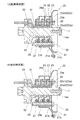
また、実施の形態に係る回転電機100において、図11に示すように、ブラシ22の第二固定バー挿入穴22aを異形にしてもよい。ブラシホルダ24内に配設されたブラシ22の第二固定バー挿入穴22aは、ベースリングプレート23と反対側の部位であり且つ固定バー29の外周面と整合する内周面を有する固定穴部22a2を含む。さらに、上記第二固定バー挿入穴22aは、ベースリングプレート23側で固定穴部22a2に隣接する部位であり且つテーパ状の内周面を有する拡大穴部22a1を含む。拡大穴部22a1は、固定穴部22a2からベースリングプレート23に向かって、固定穴部22a2の円形断面を徐々に拡大する形状を有している。具体的には、固定穴部22a2の円形断面は、回転軸7及びスリップリング31と反対方向に且つブラシホルダ24内でのブラシ22の摺動方向に沿って、長穴状の断面形状となるように徐々に拡大する。つまり、拡大穴部22a1における回転軸7に向き合う部位は、回転軸7と平行に延在し、拡大穴部22a1における回転軸7と反対側の部位は、固定穴部22a2からベースリングプレート23に向かって、回転軸7から離れるように傾斜している。
上述のような構成を有する摩耗前のブラシ22がブラシホルダ24内に配設された状態のブラシアセンブリ20を図7に示すスリップリング機構収容空間6内に配置する場合、図12の「A:配置時状態」に示すように、固定バー29が、各ベースリングプレート23の挿入穴23e、各ブラシ22の第二固定バー挿入穴22a及び各ブラシホルダ24の第一固定バー挿入穴24aに通される。これにより、各ブラシ22が、スリップリング31から離され且つ各ベースリングプレート23及び各ブラシホルダ24からも突出しない状態で保持される。よって、ブラシアセンブリ20の回転軸7への配置時に、ブラシ22がスリップリング31等と干渉することがない。
また、ブラシ22が摩耗して交換する必要が生じた場合、図12の「B:取外時状態」に示すように、アセンブリカバー21の大径部21b側から、ベースリングプレート23の挿入穴23e及びブラシ22の第二固定バー挿入穴22aに、固定バー29が挿入される。なお、ブラシ22が摩耗限界に達した場合でも、第二固定バー挿入穴22aの拡大穴部22a1が挿入穴23eに連通するように構成されている。そして、固定バー29を第二固定バー挿入穴22aに挿入して拡大穴部22a1の壁面に接触させつつ固定バー29を押し込むことによって、固定バー29が、巻きバネ25の付勢力を受けているブラシ22をスリップリング31から離すように移動させる。さらに、固定バー29が、固定穴部22a2及びブラシホルダ24の第一固定バー挿入穴24a内に通されると、ブラシ22をベースリングプレート23及びブラシホルダ24から突出しない状態で保持する。他のブラシ22についても、第二固定バー挿入穴22aに固定バー29が通ることによって、ベースリングプレート23及びブラシホルダ24から突出しない状態で、ブラシ22が保持される。よって、ブラシアセンブリ20の回転軸7からの取り外し時に、ブラシ22がスリップリング31等と干渉することがない。
なお、上述のブラシアセンブリ20の配置時及び取り外し時にブラシ22とスリップリング31との接触を防ぐためには、ブラシ22の第二固定バー挿入穴22aにおいて、拡大穴部22a1のみが設けられて固定穴部22a2が設けられていなくてもよい。
また、上述のブラシアセンブリ20の配置時及び取り外し時において、交換用ガイド41を用いてもよい。これにより、ブラシアセンブリ20の付属物との接触によるセンサ回転子14aの損傷を防ぐことができる。
また、上述のブラシアセンブリ20の配置時及び取り外し時において、交換用ガイド41を用いてもよい。これにより、ブラシアセンブリ20の付属物との接触によるセンサ回転子14aの損傷を防ぐことができる。
また、実施の形態に係る回転電機100では、第一ロータ51及びステータ53に巻線が設けられ、第二ロータ52に永久磁石が設けられていたが、巻線及び永久磁石の配置構成は、これに限定されない。2つのロータの回転軸の少なくとも一方にスリップリングが設けられればよい。
実施の形態に係る回転電機100は、第一ロータ51と第二ロータ52とステータ53とを備えるダブルロータ型の回転電機であったが、これに限定されるものでない。回転電機100は、ステータ53を備えずに、第一ロータ51及び第二ロータ52による2つのロータのみを備えるダブルロータ型モータであってもよい。或いは、ロータは1つであってもよい。回転電機は、ロータから延びる回転軸にスリップリングが設けられる構造であればよい。
実施の形態に係る回転電機100は、第一ロータ51と第二ロータ52とステータ53とを備えるダブルロータ型の回転電機であったが、これに限定されるものでない。回転電機100は、ステータ53を備えずに、第一ロータ51及び第二ロータ52による2つのロータのみを備えるダブルロータ型モータであってもよい。或いは、ロータは1つであってもよい。回転電機は、ロータから延びる回転軸にスリップリングが設けられる構造であればよい。
実施の形態に係る回転電機100では、スリップリング機構収容空間6内に導入される冷却用流体として、気体である空気が用いられていたが、冷却用流体は、空気以外の気体であってもよく、液体であってもよい。冷却用流体として使用する液体は、導電性を有しない液体がより好ましい。
実施の形態に係る回転電機100は、ハイブリッドトランスアクスル200に搭載されるとしたが、これに限定されるものでなく、いかなるものに搭載されてもよい。
実施の形態に係る回転電機100は、ハイブリッドトランスアクスル200に搭載されるとしたが、これに限定されるものでなく、いかなるものに搭載されてもよい。
Claims (8)
- 巻線を含む回転子と固定子とを備えた回転電機であって、
前記回転子から延びる回転軸に軸方向に並んで配設され、前記回転軸と一体に回転可能である複数のスリップリングと、
前記複数のスリップリングに接触するように配設される複数のブラシ、前記複数のスリップリングのそれぞれに対して配設され且つ前記ブラシを保持する複数のブラシベース、及び前記複数のブラシベースを内側で保持する筒状のアセンブリカバーを含むブラシアセンブリと、
前記複数のスリップリング及び前記ブラシアセンブリを収容する収容空間を共に形成するハウジング及びカバーと
を備え、
前記ハウジングは、前記回転軸の延びる方向に形成された開口部で開口し、
前記カバーは、前記開口部を塞ぐように前記ハウジングに取り付けられ、
前記ブラシアセンブリは、前記開口部を通って前記複数のスリップリングに着脱可能であり、
前記ブラシアセンブリは、前記アセンブリカバーに係合し且つ前記ハウジングに形成されたねじ締結穴に螺合して前記ブラシアセンブリを前記ハウジングに固定するねじ締結部材を、前記アセンブリカバーの内側に有し、
前記ねじ締結穴は、前記開口部を介して前記ねじ締結部材の着脱が可能であるように、前記ブラシアセンブリに対して前記開口部と反対側に位置する回転電機。 - 前記ブラシアセンブリは、前記回転軸の軸方向に延在し且つ前記複数のブラシベースを前記回転軸の軸方向に間隔をあけて保持する筒状の保持部を、前記アセンブリカバーの内側に含み、
前記保持部は、前記ねじ締結部材が挿通可能であり且つ前記回転軸の軸方向に延在する挿通穴を有する請求項1に記載の回転電機。 - 前記保持部は、前記アセンブリカバーに着脱可能に設けられ、
前記保持部は、前記ブラシベースの外縁を係合させることによって前記ブラシベースを保持する係合溝を有し、
前記ブラシベースが前記係合溝に係合した前記保持部及び前記ブラシベースによる組立体は、前記アセンブリカバーに対して挿入及び取り出し可能であるように構成される請求項2に記載の回転電機。 - 前記回転軸は、前記スリップリングよりも前記開口部側に、前記スリップリングの外径よりも小さい外径をもつ端部を含み、
前記端部は、前記端部の外周を囲んで前記スリップリングに隣り合って位置し且つ前記スリップリングと同等の外径を有する筒状のブラシガイド部材がガイド締結部材を用いて取り付けられるように構成される請求項1~3のいずれか一項に記載の回転電機。 - 前記回転軸の前記端部に配設されたセンサ回転子と、前記カバーに配設されたセンサ固定子とを有する回転センサをさらに備え、
前記センサ回転子の外径は、前記ブラシガイド部材の内径以下である請求項4に記載の回転電機。 - 前記回転軸の周囲に形成されて前記スリップリングを支持すると共に前記スリップリングを他の前記スリップリング及び前記回転軸から絶縁する絶縁部材をさらに備え、
前記絶縁部材は、前記スリップリング同士の間、及び前記スリップリングと前記ブラシガイド部材との間に、前記回転軸の径方向に前記スリップリングと同等の高さで突出する突起を含む請求項4または5に記載の回転電機。 - 前記ブラシ及び前記ブラシベースはそれぞれ、棒状体を挿入可能なブラシ穴及びベース穴を有し、
前記ブラシ穴は、前記ブラシ穴及び前記ベース穴に前記棒状体が挿入された状態で前記ブラシを前記スリップリングから離して位置させるように構成されると共に、前記ブラシの摩耗前後で前記ベース穴に連通するように構成される請求項1~6のいずれか一項に記載の回転電機。 - 前記回転子は、前記巻線が巻回される筒状のコアを含み、
前記ブラシアセンブリは、前記コア及び前記コアを回転自在に支持する軸受の径方向内側に延在する請求項1~7のいずれか一項に記載の回転電機。
Applications Claiming Priority (2)
| Application Number | Priority Date | Filing Date | Title |
|---|---|---|---|
| JP2014-150323 | 2014-07-24 | ||
| JP2014150323A JP6243812B2 (ja) | 2014-07-24 | 2014-07-24 | 回転電機 |
Publications (1)
| Publication Number | Publication Date |
|---|---|
| WO2016013450A1 true WO2016013450A1 (ja) | 2016-01-28 |
Family
ID=55162977
Family Applications (1)
| Application Number | Title | Priority Date | Filing Date |
|---|---|---|---|
| PCT/JP2015/070136 Ceased WO2016013450A1 (ja) | 2014-07-24 | 2015-07-14 | 回転電機 |
Country Status (2)
| Country | Link |
|---|---|
| JP (1) | JP6243812B2 (ja) |
| WO (1) | WO2016013450A1 (ja) |
Cited By (4)
| Publication number | Priority date | Publication date | Assignee | Title |
|---|---|---|---|---|
| CN109347287A (zh) * | 2018-12-10 | 2019-02-15 | 卧龙电气南阳防爆集团股份有限公司 | 一种不停机更换发电机转子接地电刷系统 |
| JP2022052201A (ja) * | 2020-09-23 | 2022-04-04 | 多摩川精機株式会社 | 扁平モータ構造 |
| CN115441632A (zh) * | 2019-12-24 | 2022-12-06 | 威灵(芜湖)电机制造有限公司 | 电机电刷、电机和洗衣机 |
| CN118575395A (zh) * | 2022-01-25 | 2024-08-30 | 日产自动车株式会社 | 旋转电机 |
Citations (3)
| Publication number | Priority date | Publication date | Assignee | Title |
|---|---|---|---|---|
| JP2001231221A (ja) * | 2000-02-18 | 2001-08-24 | Mitsubishi Electric Corp | 整流子電動機 |
| US20130140940A1 (en) * | 2011-12-06 | 2013-06-06 | Robert Bosch Gmbh | Electrical machine |
| JP2014110744A (ja) * | 2012-12-04 | 2014-06-12 | Toyota Motor Corp | スリップリング装置 |
-
2014
- 2014-07-24 JP JP2014150323A patent/JP6243812B2/ja not_active Expired - Fee Related
-
2015
- 2015-07-14 WO PCT/JP2015/070136 patent/WO2016013450A1/ja not_active Ceased
Patent Citations (3)
| Publication number | Priority date | Publication date | Assignee | Title |
|---|---|---|---|---|
| JP2001231221A (ja) * | 2000-02-18 | 2001-08-24 | Mitsubishi Electric Corp | 整流子電動機 |
| US20130140940A1 (en) * | 2011-12-06 | 2013-06-06 | Robert Bosch Gmbh | Electrical machine |
| JP2014110744A (ja) * | 2012-12-04 | 2014-06-12 | Toyota Motor Corp | スリップリング装置 |
Cited By (6)
| Publication number | Priority date | Publication date | Assignee | Title |
|---|---|---|---|---|
| CN109347287A (zh) * | 2018-12-10 | 2019-02-15 | 卧龙电气南阳防爆集团股份有限公司 | 一种不停机更换发电机转子接地电刷系统 |
| CN115441632A (zh) * | 2019-12-24 | 2022-12-06 | 威灵(芜湖)电机制造有限公司 | 电机电刷、电机和洗衣机 |
| JP2022052201A (ja) * | 2020-09-23 | 2022-04-04 | 多摩川精機株式会社 | 扁平モータ構造 |
| CN118575395A (zh) * | 2022-01-25 | 2024-08-30 | 日产自动车株式会社 | 旋转电机 |
| EP4472037A4 (en) * | 2022-01-25 | 2025-04-09 | Nissan Motor Co., Ltd. | ELECTRIC LATHE |
| US12348105B2 (en) | 2022-01-25 | 2025-07-01 | Nissan Motor Co., Ltd. | Rotating electric machine |
Also Published As
| Publication number | Publication date |
|---|---|
| JP6243812B2 (ja) | 2017-12-06 |
| JP2016025805A (ja) | 2016-02-08 |
Similar Documents
| Publication | Publication Date | Title |
|---|---|---|
| JP6175708B2 (ja) | モータ | |
| CN109478823B (zh) | 马达 | |
| JP5911034B1 (ja) | 回転電機のステータ | |
| US20060163963A1 (en) | Counter rotating generator | |
| CN114552895B (zh) | 驱动装置 | |
| JP6243812B2 (ja) | 回転電機 | |
| EP2677637A2 (en) | Eletric motor cooling | |
| KR101846604B1 (ko) | 전기 기계 냉각 시스템 및 방법 | |
| CN104283336A (zh) | 马达 | |
| JP7590882B2 (ja) | 回転電機システム | |
| EP2894333A1 (en) | Motor compressor | |
| CN102782992A (zh) | 转子、制造转子的方法以及马达 | |
| JP6950499B2 (ja) | 回転電機、及び回転電機における蓋部材の取り付け方法 | |
| JP2019030029A (ja) | モータおよびポンプ装置 | |
| US4190780A (en) | Liquid cooled disc machines | |
| CN104247227A (zh) | 电连接器及其组装方法 | |
| JP6724985B2 (ja) | 回転電機の固定子構造、及び回転電機の固定子構造の組み付け方法 | |
| CN217063416U (zh) | 一种无刷电机及电动工具 | |
| JPWO2016017179A1 (ja) | 電気モータおよび歯科装置 | |
| JPWO2018159477A1 (ja) | ポンプ装置 | |
| JP5952678B2 (ja) | 電動モータ | |
| WO2015159761A1 (ja) | スリップリング機構及びスリップリング機構を備える回転電機 | |
| US10302134B2 (en) | Bearing structure and motor | |
| JP2023519146A (ja) | 車両のための駆動装置 | |
| JP2016149866A (ja) | 車両用回転電機 |
Legal Events
| Date | Code | Title | Description |
|---|---|---|---|
| 121 | Ep: the epo has been informed by wipo that ep was designated in this application |
Ref document number: 15824656 Country of ref document: EP Kind code of ref document: A1 |
|
| NENP | Non-entry into the national phase |
Ref country code: DE |
|
| 122 | Ep: pct application non-entry in european phase |
Ref document number: 15824656 Country of ref document: EP Kind code of ref document: A1 |