WO2016013303A1 - チャック - Google Patents
チャック Download PDFInfo
- Publication number
- WO2016013303A1 WO2016013303A1 PCT/JP2015/066010 JP2015066010W WO2016013303A1 WO 2016013303 A1 WO2016013303 A1 WO 2016013303A1 JP 2015066010 W JP2015066010 W JP 2015066010W WO 2016013303 A1 WO2016013303 A1 WO 2016013303A1
- Authority
- WO
- WIPO (PCT)
- Prior art keywords
- workpiece
- screw
- gripping
- chuck
- gripped
- Prior art date
- Legal status (The legal status is an assumption and is not a legal conclusion. Google has not performed a legal analysis and makes no representation as to the accuracy of the status listed.)
- Ceased
Links
Images




Classifications
-
- B—PERFORMING OPERATIONS; TRANSPORTING
- B23—MACHINE TOOLS; METAL-WORKING NOT OTHERWISE PROVIDED FOR
- B23B—TURNING; BORING
- B23B31/00—Chucks; Expansion mandrels; Adaptations thereof for remote control
- B23B31/02—Chucks
- B23B31/10—Chucks characterised by the retaining or gripping devices or their immediate operating means
-
- B—PERFORMING OPERATIONS; TRANSPORTING
- B23—MACHINE TOOLS; METAL-WORKING NOT OTHERWISE PROVIDED FOR
- B23B—TURNING; BORING
- B23B31/00—Chucks; Expansion mandrels; Adaptations thereof for remote control
- B23B31/02—Chucks
- B23B31/10—Chucks characterised by the retaining or gripping devices or their immediate operating means
- B23B31/12—Chucks with simultaneously-acting jaws, whether or not also individually adjustable
- B23B31/20—Longitudinally-split sleeves, e.g. collet chucks
- B23B31/201—Characterized by features relating primarily to remote control of the gripping means
- B23B31/207—Characterized by features relating primarily to remote control of the gripping means using mechanical transmission through the spindle
- B23B31/2072—Axially moving cam, fixed jaws
Definitions
- the present invention relates to a chuck that can be mounted on a spindle or the like of a machine tool.
- a gripping portion that opens and closes in the radial direction has been provided, and an internal thread is formed on the inner peripheral surface of the gripping portion, and the workpiece is held and gripped by the inner peripheral surface by moving the gripping portion radially inward.
- a chuck is known (for example, Patent Document 1).
- a workpiece having a male screw portion having a male screw formed on the outer peripheral surface is known.
- the present invention solves the problems of the prior art as described above, that is, the object of the present invention is to stably hold a workpiece having a screw portion with a screw formed on the outer peripheral surface. It is to provide a chuck that can be used.
- the invention according to claim 1 includes a gripping portion that opens and closes in a radial direction, a screw is formed on an inner peripheral surface of the gripping portion, and a screw is formed on the outer peripheral surface by moving the gripping portion radially inward.
- a chuck that grips and grips a workpiece having a formed screw portion on the inner peripheral surface, wherein the screw on the inner peripheral surface of the grip portion is formed to be screwed with the screw portion of the workpiece, The gripping part is inserted into the threaded part of the work by screwing the two screws to face the gripped part of the work and grips the gripped part.
- the gripped portion in addition to the configuration of the chuck according to claim 1, the gripped portion includes a hook-shaped portion formed narrower than the screw portion, and the gripping portion is the workpiece.
- the above-mentioned problem is further solved by passing the threaded portion and gripping the hook-shaped portion as the gripped portion.
- the gripping portion grips the thread root of the thread portion of the workpiece as the gripped portion.
- the chuck according to the present invention can not only hold the workpiece by the gripping part, but also has the following specific effects.
- the opening / closing stroke of the gripping portion is screwed. Without increasing the diameter so as to be larger than the outer diameter of the portion, the gripping portion of the chuck can easily reach the gripped portion of the workpiece and the workpiece can be stably gripped.
- any part of the workpiece can be easily grasped, for example, a part close to the cutting tool in the workpiece is grasped. By doing so, it becomes possible to improve processing accuracy.
- the work can be stably gripped including the screw portion.
- the gripping part comes into contact with only the thread valley bottom of the threaded portion and exhibits gripping force.
- the workpiece can be stably gripped by preventing adverse effects on the thread crest and flank surface of the threaded portion.
- FIG. 1 is a schematic cross-sectional view showing a main shaft of a machine tool provided with a collet chuck of a first embodiment of the present invention.
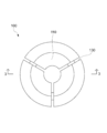
- FIG. 3 is a sectional view taken along the line 3-3 shown in FIG.
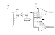
- FIG. 3 is an operation cross-sectional view showing the relationship between the collet chuck and the workpiece according to the first embodiment.
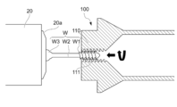
- FIG. 3 is an operation cross-sectional view showing the relationship between the collet chuck and the workpiece according to the first embodiment.
- FIG. 3 is an operation cross-sectional view showing the relationship between the collet chuck and the workpiece according to the first embodiment.
- FIG. 3 is an operation cross-sectional view showing the relationship between the collet chuck and the workpiece according to the first embodiment.
- FIG. 3 is an operation cross-sectional view showing the relationship between the collet chuck and the workpiece according to the first embodiment.
- FIG. 3 is an operation cross-sectional view showing the relationship between the collet chuck and the workpiece according to the first embodiment.
- FIG. 3 is an operation cross-sectional view showing the relationship between the collet chuck and the workpiece according to the first embodiment.
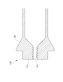
- the partial cross section figure which shows the relationship between the collet chuck of 2nd Example and a workpiece
- movement sectional drawing which shows the relationship between the collet chuck
- the present invention includes a gripping portion that opens and closes in the radial direction, a screw is formed on the inner peripheral surface of the gripping portion, and a screw portion having a screw formed on the outer peripheral surface by moving the gripping portion radially inward is provided.
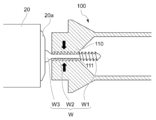
- a collet chuck 100 which is a chuck according to the first embodiment of the present invention, is mounted on a spindle S of a machine tool and opened / closed, for example, as shown in FIG.
- a spindle chuck opening / closing mechanism 10 in the spindle S is a pair of swing cams supported by an actuator cam 11 that is movable in the axial direction of the spindle by a swing lever that is operated by an actuator provided outside the spindle, and a lever holder 12 that is swingably supported.
- the lever 13 is provided.
- the lever holder 12 is positioned by a lock nut 14 screwed onto the main shaft S.
- the operating cam 11 When the operating cam 11 is moved away from the collet chuck 100 by the actuator, the operating cam 11 is inserted between the main shaft S and the lever 13, and each of the levers 13 swings and opens to move the first sleeve 15 a in the direction of the collet chuck 100.
- the second sleeve 15b that contacts the first sleeve 15a and the third sleeve 15c that contacts the second sleeve 15b move toward the collet chuck 100, and the collet chuck 100 is closed by the third sleeve 15c.
- the operating cam 11 when the operating cam 11 is moved in the direction of the collet chuck 100 by the actuator, the operating cam 11 is detached from between the main shaft S and the lever 13, the lever 13 is closed, and the first to third sleeves are operated by the action of the spring 16. 15a, 15b, 15c moves away from the collet chuck 100 and the collet chuck 100 is opened.
- the collet chuck 100 is opened and closed by the movement of the operation cam 11 and can detachably grip the workpiece W inserted into the collet chuck 100.
- the collet chuck 100 of the present embodiment includes a grip portion 110, a taper portion 120, and a slit 130, and the grip portion 110 is 3 in the circumferential direction as an example by the slit 130. It is divided.
- the gripping portion 110 is moved to be elastically bent radially inward and is closed, and grips the workpiece inserted into the gripping portion 110. can do.
- the grip portion 110 is elastically moved outward in the radial direction, and the grip of the workpiece is released.
- a female screw 111 that is a screw is formed on the inner peripheral surface of the grip portion 110.
- the workpiece W is held by a chuck 20a on the tip side of the workpiece holding portion 20 made of a spindle or the like facing the spindle S, and the spindle S side of the workpiece W is shown for the workpiece holding portion 20. It is processed with a tool that does not. Accordingly, the external thread portion W1 that is a thread portion formed at the end of the main shaft S and the external thread portion W1 are continuously formed integrally with the external thread portion W1 closer to the work holding portion 20 than the external thread portion W1, and are smaller in diameter than the external diameter of the external thread portion W1. It is assumed that a rod-shaped workpiece W having a columnar small diameter portion W2 is processed.
- the cylindrical small-diameter portion W2 constitutes a bowl-shaped portion that is formed thinner than the male screw portion W1.
- the internal thread 111 of the grip 110 is formed so as to be screwed with the external thread W1 of the workpiece W.
- the collet chuck 100 is moved with respect to the workpiece W in the Z-axis direction while rotating the spindle S manually, for example, in the Z-axis direction.
- the male screw portion W1 of the workpiece W is screwed with the female screw 111 of the gripping portion 110 corresponding to the male screw portion W1 and inserted into the collet chuck 100.
- the spindle S may be automatically rotated. Further, the workpiece side (work holding unit 20) may be rotated manually or automatically with the spindle S stopped.
- the internal thread 111 of the gripping portion 110 passes through the external thread portion W1 of the workpiece W and faces the cylindrical small diameter portion W2. , Stop relative rotation.
- the gripping portion 110 grips the cylindrical small-diameter portion W2 of the workpiece W as a gripped portion that is a small-diameter portion having a smaller diameter than the male screw portion W1. can do.
- the gripping part 110 can stably grip the vicinity of the workpiece holding part 20 side end of the work W over the entire length of the gripping part 110, and the work W can hold the work gripped by the spindle S. A portion relatively close to the tool to be processed is stably gripped. Thereafter, the workpiece holding unit 20 can be retreated relative to the spindle S by opening the chuck 20a of the workpiece holding unit 20 under control.
- a predetermined tool 21 is used to open a hole W3a in, for example, the convex curved large-diameter portion W3 on the work holder 20 side end. Etc. can be formed. As a result, the machining of the workpiece W is completed, and as an example, the bone screw can be machined.
- the collet chuck 100 is opened by control, the workpiece W and the gripping part 110 are rotated relative to each other in the opposite direction to that in FIG.
- the male screw part W1 of the work W is screwed with the female screw 111 of the gripping part 110, the work W is removed from the main shaft S, and the work W is carried out. It can be performed.
- the collet chuck 100 as the chuck of the present invention has been described as a chuck on the main shaft S side.
- the chuck is not limited to the chuck on the main shaft S side. It can also be applied.
- the internal thread 111 which is a screw on the inner peripheral surface of the gripping portion 110 is screwed with the external thread portion W1 which is the thread portion of the workpiece W.
- the grip portion 110 is inserted into the male screw portion W1 by screwing the female screw 111 and the male screw portion W1, and is opposed to the cylindrical small diameter portion W2 as the gripped portion, and grips the cylindrical small diameter portion W2.
- the inner diameter of the collet chuck 100 (gripping part 110) is formed in accordance with the outer diameter of the cylindrical small diameter part W2 and the thread root diameter of the male thread part W1, a predetermined opening / closing stroke of the gripping part 110 is achieved.
- the cylindrical small diameter portion W2 can be reliably and stably gripped after the male screw portion W1 of the workpiece W is inserted.
- the gripping part 110 passes through the male thread part W1 and grips the cylindrical small diameter part W2 formed integrally and continuously with the male thread part W1 of the workpiece W, thereby improving the processing accuracy. it can.
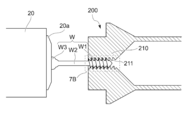
- a collet chuck 200 as a chuck according to a second embodiment of the present invention will be described with reference to FIGS. 7A and 7B.
- the collet chuck 200 according to the second embodiment is obtained by changing the position where the collet chuck 100 according to the first embodiment grips the workpiece W, and is common to the collet chuck 100 according to the first embodiment with respect to many elements. Detailed explanations of items to be omitted are omitted, and only the reference numbers in the 200s are used in common with the last two digits.
- the male screw portion W1 of the work W is screwed into and inserted into the female screw 211 of the grip portion 210 corresponding to the male screw portion W1.
- the relative rotation is stopped by the control in a state of facing the male screw portion W1.
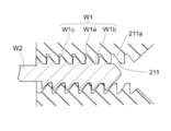
- the gripping part 210 can grip the thread valley bottom W1b of the male screw part W1 as the gripped part.
- the gripping position of the workpiece W can be adjusted according to the machining step in which the workpiece W is gripped by the spindle S and processed.
- the female screw 211 can be formed such that the thread valley bottom 211a of the female screw 211 is separated from the screw crest W1a of the male screw portion W1 when the workpiece W is gripped. Further, the female screw 211 may be formed so as to be in contact with the thread bottom W1b of the male screw portion W1 while being separated from the thread crest W1a of the male screw portion W1 and the flank surface W1c extending from the screw crest W1a to the screw valley bottom W1b. As a result, the gripping part 210 abuts only on the thread root W1b of the male threaded part and exerts a gripping force.
- the gripping part 210 grips the thread valley bottom W1b of the external thread part W1 as the gripped part.
- the thread valley bottom W1b and the small cylindrical diameter span the boundary between the external thread part W1 and the cylindrical small diameter part W2. You may hold
- the grip portion 210 grips the thread valley bottom W1b of the male screw portion W1 as the gripped portion, so that the grip portion 210 holds the workpiece W and the male screw portion W1. Can be stably gripped.
- the gripping portion 210 is attached to the workpiece W. It is possible to stably grip the workpiece W while preventing adverse effects such as damage to the screw thread top W1a and the flank surface W1c of the processed male screw portion W1.
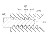
- a collet chuck 300 as a chuck according to a third embodiment of the present invention will be described with reference to FIGS. 8A and 8B.
- the collet chuck 300 according to the third embodiment is obtained by changing the diameter of the cylindrical small-diameter portion W2 of the workpiece W according to the second embodiment.
- the collet chuck 100 according to the first embodiment and the second embodiment are used. Since it is the same as that of the collet chuck 200, detailed description of the common items is omitted, and only the reference numbers in the 300s are shared by the last two digits.
- the outer diameter of the cylindrical intermediate portion W2 ′ between the male screw portion W1 of the workpiece W and the convex curved large-diameter portion W3 is the screw of the male screw portion W1. It is the same as the outer diameter at the location of the summit W1a. Note that the outer diameter of the cylindrical intermediate portion W2 ′ may be larger than the outer diameter of the thread crest W1a of the male screw portion W1. Even in such a case, in the collet chuck 300 as the chuck according to the third embodiment of the present invention, the internal thread 311 of the gripping part 310 grips the thread valley bottom W1b of the external thread part W1 as the gripped part. The grip portion 310 can stably grip the workpiece W including the male screw portion W1.
Landscapes
- Engineering & Computer Science (AREA)
- Mechanical Engineering (AREA)
- Gripping On Spindles (AREA)
Abstract
外周面にネジが形成されたネジ部分を有するワークを安定して把持することができるチャックを提供すること。 径方向に開閉移動する把持部(110)を備え、この把持部(110)の内周面にネジ(111)が形成され、把持部(110)の径方向内側への移動によって、外周面にネジが形成されたネジ部分(W1)を有するワーク(W)を、内周面で挟持して把持するチャック(100)であって、ネジ(111)が、ワーク(W)のネジ部分(W1)と螺合するように形成され、把持部(110)が、ネジ(111)とネジ部分(W1)との螺合によって、ネジ部分(W1)に挿通されてワーク(W)の被把持部(W2)と対向し、被把持部(W2)を把持するように構成されたチャック(100)。
Description
本発明は、工作機械の主軸等に装着可能なチャックに関する。
従来、径方向に開閉移動する把持部を備え、該把持部の内周面に雌ねじが形成され、前記把持部の径方向内側への移動によって、ワークを前記内周面で挟持して把持するチャックが知られている(例えば、特許文献1)。
また一般的に、外周面に雄ねじが形成された雄ねじ部分を有するワークが知られている。
また一般的に、外周面に雄ねじが形成された雄ねじ部分を有するワークが知られている。
しかしながら、上述したワークを前記チャックで把持する場合、雄ねじ部分を有するワークの安定把持は容易ではない。
そこで、本発明は、前述したような従来技術の問題を解決するものであって、すなわち、本発明の目的は、外周面にネジが形成されたネジ部分を有するワークを安定して把持することができるチャックを提供することである。
本請求項1に係る発明は、径方向に開閉移動する把持部を備え、該把持部の内周面にネジが形成され、前記把持部の径方向内側への移動によって、外周面にネジが形成されたネジ部分を有するワークを、前記内周面で挟持して把持するチャックであって、前記把持部の内周面のネジが、前記ワークのネジ部分と螺合するように形成され、前記把持部が、前記両ネジの螺合によって、前記ワークのネジ部分に挿通されてワークの被把持部と対向し、該被把持部を把持するように構成されたことにより、前述した課題を解決するものである。
本請求項2に係る発明は、請求項1に記載されたチャックの構成に加えて、前記被把持部が、前記ネジ部分より細く形成された杆状部分からなり、前記把持部が、前記ワークのネジ部分を通過し、前記杆状部分を前記被把持部として把持することにより、前述した課題をさらに解決するものである。
本請求項3に係る発明は、請求項1又は請求項2に記載されたチャックの構成に加えて、前記把持部が、前記ワークのネジ部分のねじ谷底を前記被把持部として把持することにより、前述した課題をさらに解決するものである。
本請求項4に係る発明は、請求項3に記載されたチャックの構成に加えて、前記把持部のネジが、ワークの把持状態で、ねじ谷底が前記ワークのネジ部分のねじ山頂から離間するように形成されていることにより、前述した課題をさらに解決するものである。
本発明のチャックは、把持部により、ワークを把持することができるばかりでなく、以下のような特有の効果を奏することができる。
本請求項1に係る発明のチャックによれば、把持部がワークのネジ部分と螺合してネジ部分に円滑に挿通され、ワークの被把持部と対向するため、把持部の開閉ストロークをネジ部分の外径より大きく拡径するように拡大すること無く、チャックの把持部をワークの被把持部に容易に到達させてワークを安定して把持することができる。
本請求項2に係る発明のチャックによれば、請求項1に係る発明が奏する効果に加えて、ワークの任意の部分を容易に把持することができ、例えばワークにおける切削工具に近い箇所を把持することによって、加工精度を向上させることが可能となる。
本請求項3に係る発明のチャックによれば、請求項1又は請求項2に係る発明が奏する効果に加えて、ワークを、ネジ部分を含めて安定して把持することができる。
本請求項4に係る発明のチャックによれば、請求項3に係る発明が奏する効果に加えて、把持部がネジ部分のねじ谷底のみと当接して把持力を発揮するため、把持部がワークに加工されたネジ部分のねじ山頂やフランク面への悪影響を防止してワークを安定的に把持することができる。
本発明は、径方向に開閉移動する把持部を備え、この把持部の内周面にネジが形成され、把持部の径方向内側への移動によって、外周面にネジが形成されたネジ部分を有するワークを、内周面で挟持して把持するチャックであって、把持部の内周面のネジが、ワークのネジと螺合するように形成され、把持部が、両ネジの螺合によって、ワークのネジ部分に挿通されてワークの被把持部と対向し、被把持部を把持するように構成されたことにより、ネジ部分を有するワークに対して把持部の開閉ストロークを必要以上に拡大することなくワークのネジ部分を把持部内に挿通して、ワークの被把持部を安定して把持するものであれば、その具体的な実施態様は、如何なるものであっても構わない。
本発明の第1実施例のチャックであるコレットチャック100は、例えば、図1に示すように、工作機械の主軸Sに装着されて開閉され、着脱自在にワークを把持する。
主軸Sにおける主軸チャック開閉機構10は、主軸外方に設けられたアクチュエータによって作動する揺動レバーにより主軸の軸方向に移動可能な作動カム11と、レバーホルダ12に揺動可能に支持された一対のレバー13とを有している。
上記レバーホルダ12は、主軸Sに螺合装着されているロックナット14によって、位置決めされる。
主軸Sにおける主軸チャック開閉機構10は、主軸外方に設けられたアクチュエータによって作動する揺動レバーにより主軸の軸方向に移動可能な作動カム11と、レバーホルダ12に揺動可能に支持された一対のレバー13とを有している。
上記レバーホルダ12は、主軸Sに螺合装着されているロックナット14によって、位置決めされる。
作動カム11は、アクチュエータによってコレットチャック100から離れる方向に移動すると主軸Sとレバー13との間に挿入され、レバー13の各々が揺動して開き、第1スリーブ15aをコレットチャック100の方向に押し、それにより第1スリーブ15aに当接する第2スリーブ15b、さらに、第2スリーブ15bに当接する第3スリーブ15cがコレットチャック100の方向に移動し、第3スリーブ15cによってコレットチャック100が閉じる。
一方、作動カム11がアクチュエータによってコレットチャック100の方向に移動することによって、主軸Sとレバー13との間から作動カム11が外れ、レバー13が閉じ、スプリング16の作用で第1乃至第3スリーブ15a、15b、15cがコレットチャック100から離れる方向に移動してコレットチャック100が開く。
コレットチャック100は、作動カム11の移動によって開閉し、コレットチャック100内に挿入されるワークWを着脱自在に把持することができる。
コレットチャック100は、作動カム11の移動によって開閉し、コレットチャック100内に挿入されるワークWを着脱自在に把持することができる。
図2および図3に示すように、本実施例のコレットチャック100は、把持部110と、テーパ部120と、スリット130とを有し、把持部110は、スリット130によって一例として周方向に3分割されている。
把持部110は、上述したように第3スリーブ15cがテーパ部120を押圧することによって、弾力的に径方向内側に撓むように移動して閉状態となり、把持部110内に挿入されたワークを把持することができる。
第3スリーブ15cによるテーパ部120の押圧が解除されると、把持部110は径方向外側に弾力的に移動して開き、ワークの把持は解除される。
把持部110の内周面にはネジである雌ねじ111が形成されている。
把持部110は、上述したように第3スリーブ15cがテーパ部120を押圧することによって、弾力的に径方向内側に撓むように移動して閉状態となり、把持部110内に挿入されたワークを把持することができる。
第3スリーブ15cによるテーパ部120の押圧が解除されると、把持部110は径方向外側に弾力的に移動して開き、ワークの把持は解除される。
把持部110の内周面にはネジである雌ねじ111が形成されている。
図4Aに示すように、例えば、ワークWが、主軸Sに対向する主軸等からなるワーク保持部20の先端側のチャック20aによって保持され、ワークWにおける主軸S側が、ワーク保持部20用の図示しない工具によって加工される。
これにより、主軸S側端に形成されたネジ部分である雄ねじ部分W1と、雄ねじ部分W1よりワーク保持部20側に雄ねじ部分W1に連続して一体形成されて雄ねじ部分W1の外径より小径な円柱状小径部分W2とを有している棒状のワークWが加工されるものとする。
円柱状小径部分W2は、雄ねじ部分W1より細く形成された杆状部分を構成している。
把持部110の雌ねじ111は、ワークWの雄ねじ部分W1と螺合するように形成されている。
これにより、主軸S側端に形成されたネジ部分である雄ねじ部分W1と、雄ねじ部分W1よりワーク保持部20側に雄ねじ部分W1に連続して一体形成されて雄ねじ部分W1の外径より小径な円柱状小径部分W2とを有している棒状のワークWが加工されるものとする。
円柱状小径部分W2は、雄ねじ部分W1より細く形成された杆状部分を構成している。
把持部110の雌ねじ111は、ワークWの雄ねじ部分W1と螺合するように形成されている。
ワークWを主軸Sで把持する場合、まず、図4Bに示すように、主軸Sをコレットチャック100の開状態で、例えば、手動で回転させながらZ軸方向に、コレットチャック100がワークWに対して接近する方向へ移動させ、ワークWの雄ねじ部分W1を、この雄ねじ部分W1と対応関係にある把持部110の雌ねじ111と螺合させてコレットチャック100に挿通させる。
なお、この際、主軸Sを自動で回転させてもよい。
また、主軸Sを停止させた状態で、ワーク側(ワーク保持部20)を手動または自動で回転させてもよい。
また、主軸Sを停止させた状態で、ワーク側(ワーク保持部20)を手動または自動で回転させてもよい。
図5Aに示すように、ワークWと把持部110とを相対的に回転させ続けて、把持部110の雌ねじ111が、ワークWの雄ねじ部分W1を通過し、円柱状小径部分W2と対向したとき、相対的な回転を停止する。
図5Bに示すように、制御によりコレットチャック100を閉状態とすることによって、把持部110が、ワークWの円柱状小径部分W2を、雄ねじ部分W1より小径の小径部位である被把持部として把持することができる。
これにより、把持部110はワークWのワーク保持部20側端の近傍を把持部110の長さ全体に亘って安定して把持することができ、ワークWは、主軸Sに把持されたワークを加工する工具に比較的近い箇所が安定的に把持される。
その後、制御によりワーク保持部20のチャック20aを開状態とすることによって、ワーク保持部20を主軸Sに対して相対的に退避させることができる。
図5Bに示すように、制御によりコレットチャック100を閉状態とすることによって、把持部110が、ワークWの円柱状小径部分W2を、雄ねじ部分W1より小径の小径部位である被把持部として把持することができる。
これにより、把持部110はワークWのワーク保持部20側端の近傍を把持部110の長さ全体に亘って安定して把持することができ、ワークWは、主軸Sに把持されたワークを加工する工具に比較的近い箇所が安定的に把持される。
その後、制御によりワーク保持部20のチャック20aを開状態とすることによって、ワーク保持部20を主軸Sに対して相対的に退避させることができる。
ワーク保持部20の退避後、図6に示すように、主軸Sを回転させることによって、所定の工具21によって、例えばワークWにおけるワーク保持部20側端の凸曲面状大径部分W3に穴W3a等を形成することができる。
これによりワークWの加工が完了し、一例としてボーンスクリュの加工をおこなうことができる。
これによりワークWの加工が完了し、一例としてボーンスクリュの加工をおこなうことができる。
なお、加工後のワークWを保持した状態で、制御によりコレットチャック100を開状態とし、ワークWと把持部110とを図4Bのときと逆方向に相対的に回転させるとともに、主軸SをZ軸方向においてワーク保持部20から離間する方向へ移動させることによって、ワークWの雄ねじ部分W1を把持部110の雌ねじ111と螺合させて、ワークWを主軸Sから脱抜し、ワークWの搬出を行うことができる。
なお、本実施例では、本発明のチャックとしてのコレットチャック100を主軸S側のチャックとして説明したが、主軸S側のチャックに限られるものではなく、例えばワーク保持部20を構成する主軸等に適用することもできる。
なお、本実施例では、本発明のチャックとしてのコレットチャック100を主軸S側のチャックとして説明したが、主軸S側のチャックに限られるものではなく、例えばワーク保持部20を構成する主軸等に適用することもできる。
このように本発明の第1実施例であるチャックとしてのコレットチャック100は、把持部110の内周面のネジである雌ねじ111が、ワークWのネジ部分である雄ねじ部分W1と螺合するように形成され、把持部110が、雌ねじ111と雄ねじ部分W1との螺合によって、雄ねじ部分W1に挿通されて被把持部としての円柱状小径部分W2と対向し、円柱状小径部分W2を把持するように構成されたことにより、コレットチャック100(把持部110)の内径を円柱状小径部分W2の外径や雄ねじ部分W1のねじ谷底径に応じて形成すれば、把持部110の既定の開閉ストロークを拡径するように拡大する必要も無く、ワークWの雄ねじ部分W1を挿通させた後に円柱状小径部分W2を確実かつ安定して把持することができる。
また、把持部110が、雄ねじ部分W1を通過し、ワークWの雄ねじ部分W1に連続して一体形成された円柱状小径部分W2を被把持部として把持することにより、加工精度を向上させることができる。
続いて、本発明の第2実施例であるチャックとしてのコレットチャック200について、図7Aおよび図7Bに基づいて説明する。
第2実施例のコレットチャック200は、第1実施例のコレットチャック100がワークWにおける把持する位置を変更したものであり、多くの要素について第1実施例のコレットチャック100と共通するので、共通する事項については詳しい説明を省略し、下2桁が共通する200番台の符号を付すのみとする。
第2実施例のコレットチャック200は、第1実施例のコレットチャック100がワークWにおける把持する位置を変更したものであり、多くの要素について第1実施例のコレットチャック100と共通するので、共通する事項については詳しい説明を省略し、下2桁が共通する200番台の符号を付すのみとする。
図7Aおよび図7Bに示すように、第2実施例では、ワークWの雄ねじ部分W1を、この雄ねじ部分W1と対応関係にある把持部210の雌ねじ211と螺合させて挿通させ、雌ねじ211が雄ねじ部分W1と対向した状態で、制御により相対的な回転を停止する。
そして、制御によりコレットチャック200を閉状態とすることによって、把持部210が、雄ねじ部分W1のねじ谷底W1bを被把持部として把持することができる。
これにより、ワークWを主軸Sで把持して加工する加工工程に応じてワークWの把持位置を調節することができる。
そして、制御によりコレットチャック200を閉状態とすることによって、把持部210が、雄ねじ部分W1のねじ谷底W1bを被把持部として把持することができる。
これにより、ワークWを主軸Sで把持して加工する加工工程に応じてワークWの把持位置を調節することができる。
さらに、雌ねじ211は、ワークWの把持状態で、雌ねじ211のねじ谷底211aが雄ねじ部分W1のねじ山頂W1aから離間するように形成することができる。
また、雌ねじ211を、雄ねじ部分W1のねじ山頂W1aおよびこのねじ山頂W1aからねじ谷底W1bに至るフランク面W1cから離間して雄ねじ部分W1のねじ谷底W1bと当接するように形成してもよい。
これにより、把持部210が雄ねじ部のねじ谷底W1bのみと当接して把持力を発揮する。
なお、本実施例では、把持部210が、雄ねじ部分W1のねじ谷底W1bを被把持部として把持したが、雄ねじ部分W1と円柱状小径部分W2との境界にまたがってねじ谷底W1bおよび円柱状小径部分W2の両方を把持してもよい。
また、雌ねじ211を、雄ねじ部分W1のねじ山頂W1aおよびこのねじ山頂W1aからねじ谷底W1bに至るフランク面W1cから離間して雄ねじ部分W1のねじ谷底W1bと当接するように形成してもよい。
これにより、把持部210が雄ねじ部のねじ谷底W1bのみと当接して把持力を発揮する。
なお、本実施例では、把持部210が、雄ねじ部分W1のねじ谷底W1bを被把持部として把持したが、雄ねじ部分W1と円柱状小径部分W2との境界にまたがってねじ谷底W1bおよび円柱状小径部分W2の両方を把持してもよい。
本発明の第2実施例であるチャックとしてのコレットチャック200は、把持部210が、雄ねじ部分W1のねじ谷底W1bを被把持部として把持することにより、把持部210がワークWを、雄ねじ部分W1を含めて安定して把持することができる。
また、雌ねじ211が、ワークWの把持状態で、雌ねじ211のねじ谷底211aが雄ねじ部分W1のねじ山頂W1aやフランク面W1cから離間するように形成されていることにより、把持部210がワークWに加工された雄ねじ部分W1のねじ山頂W1aおよびフランク面W1cに対して損傷等の悪影響を防止してワークWを安定的に把持することができる。
続いて、本発明の第3実施例であるチャックとしてのコレットチャック300について、図8Aおよび図8Bに基づいて説明する。
第3実施例のコレットチャック300は、第2実施例のワークWの円柱状小径部分W2の径を変更したものであり、多くの要素について第1実施例のコレットチャック100および第2実施例のコレットチャック200と共通するので、共通する事項については詳しい説明を省略し、下2桁が共通する300番台の符号を付すのみとする。
第3実施例のコレットチャック300は、第2実施例のワークWの円柱状小径部分W2の径を変更したものであり、多くの要素について第1実施例のコレットチャック100および第2実施例のコレットチャック200と共通するので、共通する事項については詳しい説明を省略し、下2桁が共通する300番台の符号を付すのみとする。
図8Aおよび図8Bに示すように、第3実施例では、ワークWの雄ねじ部分W1と凸曲面状大径部分W3との間の円柱状中間部分W2’の外径は、雄ねじ部分W1のねじ山頂W1aの箇所の外径と同じである。
なお、円柱状中間部分W2’の外径は、雄ねじ部分W1のねじ山頂W1aの箇所の外径より大きくてもよい。
このような場合であっても、本発明の第3実施例であるチャックとしてのコレットチャック300は、把持部310の雌ねじ311が、雄ねじ部分W1のねじ谷底W1bを被把持部として把持することにより、把持部310がワークWを、雄ねじ部分W1を含めて安定して把持することができる。
なお、円柱状中間部分W2’の外径は、雄ねじ部分W1のねじ山頂W1aの箇所の外径より大きくてもよい。
このような場合であっても、本発明の第3実施例であるチャックとしてのコレットチャック300は、把持部310の雌ねじ311が、雄ねじ部分W1のねじ谷底W1bを被把持部として把持することにより、把持部310がワークWを、雄ねじ部分W1を含めて安定して把持することができる。
100、200、300 ・・・ コレットチャック(チャック)
110、210、310 ・・・ 把持部
111、211、311 ・・・ 雌ねじ(ネジ)
120 ・・・ テーパ部
130 ・・・ スリット
W ・・・ ワーク
W1 ・・・ 雄ねじ部分(ネジ部分)
W1a ・・・ ねじ山頂
W1b ・・・ ねじ谷底
W1c ・・・ フランク面
W2 ・・・ 円柱状小径部分
W2’ ・・・ 円柱状中間部分
W3 ・・・ 凸曲面状大径部分
W3a ・・・ 穴
110、210、310 ・・・ 把持部
111、211、311 ・・・ 雌ねじ(ネジ)
120 ・・・ テーパ部
130 ・・・ スリット
W ・・・ ワーク
W1 ・・・ 雄ねじ部分(ネジ部分)
W1a ・・・ ねじ山頂
W1b ・・・ ねじ谷底
W1c ・・・ フランク面
W2 ・・・ 円柱状小径部分
W2’ ・・・ 円柱状中間部分
W3 ・・・ 凸曲面状大径部分
W3a ・・・ 穴
Claims (4)
- 径方向に開閉移動する把持部を備え、該把持部の内周面にネジが形成され、前記把持部の径方向内側への移動によって、外周面にネジが形成されたネジ部分を有するワークを、前記内周面で挟持して把持するチャックであって、
前記把持部の内周面のネジが、前記ワークのネジ部分と螺合するように形成され、
前記把持部が、前記両ネジの螺合によって、前記ワークのネジ部分に挿通されてワークの被把持部と対向し、該被把持部を把持するように構成されたことを特徴とするチャック。 - 前記被把持部が、前記ネジ部分より細く形成された杆状部分からなり、
前記把持部が、前記ワークのネジ部分を通過し、前記杆状部分を前記被把持部として把持することを特徴とする請求項1に記載のチャック。 - 前記把持部が、前記ワークのネジ部分のねじ谷底を前記被把持部として把持することを特徴とする請求項1又は請求項2に記載のチャック。
- 前記把持部のネジが、ワークの把持状態で、ねじ谷底が前記ワークのネジ部分のねじ山頂から離間するように形成されていることを特徴とする請求項3に記載のチャック。
Priority Applications (1)
| Application Number | Priority Date | Filing Date | Title |
|---|---|---|---|
| JP2016535830A JP6571651B2 (ja) | 2014-07-22 | 2015-06-03 | チャック方法 |
Applications Claiming Priority (2)
| Application Number | Priority Date | Filing Date | Title |
|---|---|---|---|
| JP2014148892 | 2014-07-22 | ||
| JP2014-148892 | 2014-07-22 |
Publications (1)
| Publication Number | Publication Date |
|---|---|
| WO2016013303A1 true WO2016013303A1 (ja) | 2016-01-28 |
Family
ID=55162839
Family Applications (1)
| Application Number | Title | Priority Date | Filing Date |
|---|---|---|---|
| PCT/JP2015/066010 Ceased WO2016013303A1 (ja) | 2014-07-22 | 2015-06-03 | チャック |
Country Status (3)
| Country | Link |
|---|---|
| JP (1) | JP6571651B2 (ja) |
| TW (1) | TW201604423A (ja) |
| WO (1) | WO2016013303A1 (ja) |
Citations (6)
| Publication number | Priority date | Publication date | Assignee | Title |
|---|---|---|---|---|
| US2454829A (en) * | 1944-01-07 | 1948-11-30 | Aircraft Marine Prod Inc | Electrical connector |
| US2670963A (en) * | 1950-11-02 | 1954-03-02 | Leonard C Osborn | Chuck |
| US3537714A (en) * | 1968-01-02 | 1970-11-03 | Otis F Anderson | Chucking fixture assembly |
| JPS60161568U (ja) * | 1984-04-03 | 1985-10-26 | トヨタ自動車株式会社 | ねじ軸のチヤツク装置 |
| DE3427754A1 (de) * | 1984-07-27 | 1986-01-30 | Zbigniew 8240 Berchtesgaden Mroczkowski | Stabfoermiges werkzeug zum schneiden von spangebend verformbaren werkstoffen |
| JP2005249767A (ja) * | 2004-03-05 | 2005-09-15 | Sakamura Mach Co Ltd | 軸力保障ボルトの検査システム |
-
2015
- 2015-06-03 WO PCT/JP2015/066010 patent/WO2016013303A1/ja not_active Ceased
- 2015-06-03 JP JP2016535830A patent/JP6571651B2/ja active Active
- 2015-06-03 TW TW104117979A patent/TW201604423A/zh unknown
Patent Citations (6)
| Publication number | Priority date | Publication date | Assignee | Title |
|---|---|---|---|---|
| US2454829A (en) * | 1944-01-07 | 1948-11-30 | Aircraft Marine Prod Inc | Electrical connector |
| US2670963A (en) * | 1950-11-02 | 1954-03-02 | Leonard C Osborn | Chuck |
| US3537714A (en) * | 1968-01-02 | 1970-11-03 | Otis F Anderson | Chucking fixture assembly |
| JPS60161568U (ja) * | 1984-04-03 | 1985-10-26 | トヨタ自動車株式会社 | ねじ軸のチヤツク装置 |
| DE3427754A1 (de) * | 1984-07-27 | 1986-01-30 | Zbigniew 8240 Berchtesgaden Mroczkowski | Stabfoermiges werkzeug zum schneiden von spangebend verformbaren werkstoffen |
| JP2005249767A (ja) * | 2004-03-05 | 2005-09-15 | Sakamura Mach Co Ltd | 軸力保障ボルトの検査システム |
Also Published As
| Publication number | Publication date |
|---|---|
| JPWO2016013303A1 (ja) | 2017-04-27 |
| TW201604423A (zh) | 2016-02-01 |
| JP6571651B2 (ja) | 2019-09-04 |
Similar Documents
| Publication | Publication Date | Title |
|---|---|---|
| US2842020A (en) | Wrench holder | |
| JP6208851B2 (ja) | コレットチャック、チャック装置、及び、加工製品の製造方法 | |
| FR2910828B1 (fr) | Dispositif d'outil a expansion pour pince sur machine a realiser des emboitures aux extremites de tuyaux en matiere plastique ou composite | |
| KR101577461B1 (ko) | 자동 선반의 소재 조임력 조절장치 | |
| CN106624009A (zh) | 一种车床夹具 | |
| JP6571651B2 (ja) | チャック方法 | |
| US1372482A (en) | Chuck for holding tools and bars | |
| US2788980A (en) | Chuck for threading nipples | |
| JP2000343307A (ja) | 引き込み式チャック | |
| JP7197224B2 (ja) | 把持工具、および、把持工具の使用方法 | |
| CN106141947A (zh) | 一种手动工具 | |
| US3589708A (en) | Clamping device | |
| JP2011255460A (ja) | 工作機械 | |
| JP7096115B2 (ja) | 工作機械、ねじ転造工具およびねじ転造方法 | |
| CN211218739U (zh) | 用于通用三爪卡盘的螺纹可调分离卡爪装置 | |
| CN202667838U (zh) | 一种套丝器 | |
| US2682413A (en) | Chuck | |
| KR200193339Y1 (ko) | 태핑용 지그 | |
| US1159247A (en) | Chuck. | |
| CN204565351U (zh) | 螺钉车螺纹用装置 | |
| JP2014061573A (ja) | コレットチャック装置およびこのコレットチャック装置を備えた工作機械 | |
| JP5587460B1 (ja) | チャック | |
| JP3163325U (ja) | ラブチャック | |
| JP2001001213A (ja) | タップホルダ | |
| US2848917A (en) | Right and left thread, slidable jaw, handle-actuated wrench |
Legal Events
| Date | Code | Title | Description |
|---|---|---|---|
| 121 | Ep: the epo has been informed by wipo that ep was designated in this application |
Ref document number: 15824055 Country of ref document: EP Kind code of ref document: A1 |
|
| ENP | Entry into the national phase |
Ref document number: 2016535830 Country of ref document: JP Kind code of ref document: A |
|
| NENP | Non-entry into the national phase |
Ref country code: DE |
|
| 122 | Ep: pct application non-entry in european phase |
Ref document number: 15824055 Country of ref document: EP Kind code of ref document: A1 |