WO2016013101A1 - 成形制御装置、成形制御方法、および、プログラム - Google Patents
成形制御装置、成形制御方法、および、プログラム Download PDFInfo
- Publication number
- WO2016013101A1 WO2016013101A1 PCT/JP2014/069644 JP2014069644W WO2016013101A1 WO 2016013101 A1 WO2016013101 A1 WO 2016013101A1 JP 2014069644 W JP2014069644 W JP 2014069644W WO 2016013101 A1 WO2016013101 A1 WO 2016013101A1
- Authority
- WO
- WIPO (PCT)
- Prior art keywords
- polishing tool
- dressing
- dressing surface
- posture
- tool
- Prior art date
- Legal status (The legal status is an assumption and is not a legal conclusion. Google has not performed a legal analysis and makes no representation as to the accuracy of the status listed.)
- Ceased
Links
Images







Classifications
-
- B—PERFORMING OPERATIONS; TRANSPORTING
- B24—GRINDING; POLISHING
- B24B—MACHINES, DEVICES, OR PROCESSES FOR GRINDING OR POLISHING; DRESSING OR CONDITIONING OF ABRADING SURFACES; FEEDING OF GRINDING, POLISHING, OR LAPPING AGENTS
- B24B53/00—Devices or means for dressing or conditioning abrasive surfaces
- B24B53/02—Devices or means for dressing or conditioning abrasive surfaces of plane surfaces on abrasive tools
-
- B—PERFORMING OPERATIONS; TRANSPORTING
- B24—GRINDING; POLISHING
- B24B—MACHINES, DEVICES, OR PROCESSES FOR GRINDING OR POLISHING; DRESSING OR CONDITIONING OF ABRADING SURFACES; FEEDING OF GRINDING, POLISHING, OR LAPPING AGENTS
- B24B53/00—Devices or means for dressing or conditioning abrasive surfaces
- B24B53/04—Devices or means for dressing or conditioning abrasive surfaces of cylindrical or conical surfaces on abrasive tools or wheels
-
- B—PERFORMING OPERATIONS; TRANSPORTING
- B24—GRINDING; POLISHING
- B24B—MACHINES, DEVICES, OR PROCESSES FOR GRINDING OR POLISHING; DRESSING OR CONDITIONING OF ABRADING SURFACES; FEEDING OF GRINDING, POLISHING, OR LAPPING AGENTS
- B24B53/00—Devices or means for dressing or conditioning abrasive surfaces
- B24B53/06—Devices or means for dressing or conditioning abrasive surfaces of profiled abrasive wheels
- B24B53/08—Devices or means for dressing or conditioning abrasive surfaces of profiled abrasive wheels controlled by information means, e.g. patterns, templets, punched tapes or the like
Definitions
- the present invention relates to a molding control device, a molding control method, and a program for molding a polishing tool.
- An industrial robot automatically controls the operation of an arm (manipulator) according to a detection value of a force sensor or the like to assemble and process members.
- a force sensor for example, in the case of the configuration described in Patent Document 1, a 6-axis force sensor that detects the force and torque acting on the arm is provided, and the work gripped on the arm is pressed against a rotating polishing tool (grinding stone). To polish.
- a dressing member (grinding stone) is set on the arm instead of the workpiece, the dressing member is pressed against the polishing tool, and dressing is performed until the polishing tool has a desired shape.
- the arm is controlled so that the output value of the six-axis force sensor becomes a set value, and the set value is PID (Proportional Integral Derivative) controlled by the computer.
- Patent Document 1 does not specify how to determine that the polishing tool has a desired shape and end dressing.
- the dressing of the polishing tool is automated as described above, it is difficult to accurately control the position of the polishing tool pressed against the dressing member after the polishing tool is brought into contact with the dressing member. .
- the present invention has been made in view of such problems, and an object of the present invention is to provide a molding control device, a molding control method, and a program capable of realizing high shape accuracy in dressing.
- a molding control apparatus of the present invention includes a robot operation control unit that moves a polishing tool, contacts the dressing surface while rotating the polishing tool, and molds and polishes the polishing tool.
- a force detection output unit that outputs an output value indicating a load acting on the polishing tool, and the robot motion control unit has a tool rotation axis of the polishing tool relative to the dressing surface or the position specifying surface.
- the polishing tool In the first posture that is vertical, the polishing tool is moved in a direction close to the dressing surface or the position specifying surface, an output value output from the force detection output unit exceeds a threshold value, and the polishing tool is The position that is in contact with the dressing surface or the position specifying surface is the reference position, and the movement is completed on the dressing surface or the position facing the dressing surface based on the reference position.
- the polishing tool is moved to a position, and in the movement process from the reference position to the movement completion position, the polishing tool is moved from the first position to the second position where the tool rotation axis is inclined with respect to the dressing surface. And is brought into contact with the dressing surface while being rotated in the second posture.
- the robot motion control unit When the output value output from the force detection output unit exceeds the threshold, the robot motion control unit is on the tool rotation axis in contact with the dressing surface or the position specifying surface of the polishing tool.
- the polishing tool may be inclined to the second posture with the point as a rotation center point.
- the robot motion control unit moves the polishing tool in the first posture in a direction close to the dressing surface, and from the reference position by a separation distance in a direction perpendicular to the dressing surface,
- the distance from the reference position toward the separation direction opposite to the approaching direction is greater than or equal to the separation distance.
- the polishing tool is moved, and a moving distance of the polishing tool is measured in the moving process, and after the polishing tool moves more than the separation distance, the polishing tool is moved from the first posture to the second position. You may make it move to the said close direction to the said movement completion position while making it rotate to a attitude
- the robot motion control unit may determine whether or not the movement to the movement completion position is completed while the polishing tool is rotated in the second posture and brought into contact with the dressing surface.
- the robot operation control unit stops the rotation of the polishing tool while maintaining the second posture, and moves the dressing surface or the position specifying surface closer to a direction where the reference position is set.
- the polishing tool is moved, and it is determined whether or not the movement to the movement completion position is completed from the difference between the position where the output value output from the force detection output unit exceeds the threshold and the reference position. Also good.
- the molding control method of the present invention provides the dressing surface or the position specifying surface in a first posture in which the tool rotation axis of the polishing tool is perpendicular to the dressing surface or the position specifying surface.
- the polishing tool is moved in a direction close to the output value, the output value indicating the load acting on the polishing tool exceeds a threshold, and the position where the polishing tool is in contact with the dressing surface or the position specifying surface is a reference position, Based on the reference position, the polishing tool is moved to a movement completion position on the dressing surface or a position facing the dressing surface, and the polishing tool is moved in the movement process from the reference position to the movement completion position.
- the tool rotation axis is displaced from the first posture to a second posture inclined with respect to the dressing surface and rotated in the second posture. Characterized in that is brought into contact with the dressing surface while.
- a force detection output unit that outputs an output value indicating a load acting on the polishing tool is provided, and the polishing tool is moved so that the polishing tool is rotated and brought into contact with the dressing surface.
- a computer functioning as a robot operation control unit for shaping and polishing the polishing tool in a first posture in which a tool rotation axis of the polishing tool is perpendicular to the dressing surface or position specifying surface. The polishing tool is moved in a direction close to the position specifying surface, an output value output from the force detection output unit exceeds a threshold value, and a position where the polishing tool is in contact with the dressing surface or the position specifying surface is determined.
- a reference position and based on the reference position, the polishing tool is moved to a movement completion position on the dressing surface or a position facing the dressing surface; In the movement process from the reference position to the movement completion position, the polishing tool is displaced from the first posture to a second posture in which the tool rotation axis is inclined with respect to the dressing surface, and A program for executing a process of contacting the dressing surface while rotating in the second posture is provided.
- the robot motion control unit specifies the movement completion position based on the reference position when the output value of the force detection output unit exceeds the threshold value. Therefore, the positional accuracy of the movement completion position is high, and the shape accuracy of the polishing tool that has completed dressing can be increased. Therefore, according to the present invention, it is possible to achieve high shape accuracy in dressing.
- FIG. 1 is an explanatory diagram showing the overall configuration of the molding control device 1 during polishing of the workpiece W.
- the molding control device 1 includes a robot arm 2.
- the robot arm 2 has a plurality of joints 2a (joints), and has a structure in which a node 2b (Link) connected by the joints 2a can rotate around the joints 2a.
- the electric parts 3 are constituted by motors, for example, and are provided in the respective joint parts 2a, and give power to rotate the node parts 2b around the joint parts 2a by the power of the power source connected to the main body 2c.
- a motor 3 a that constitutes a part of the motor unit 3 is also provided at the tip of the robot arm 2.
- a tool holder 4 is provided at the shaft tip of the motor 3a.
- the tool holding unit 4 is formed to be rotatable by a motor 3a while holding the polishing tool 5.
- the polishing tool 5 is, for example, a grindstone, and is held by the tool holding unit 4 so that the axis of the polishing tool 5 is positioned on the extension of the rotation shaft of the shaft of the motor 3a.
- the robot motion control unit 7 (Robot motion control unit) is composed of, for example, a control PC 7a (control motion PC) and a robot controller 7b (Robot motion controller).
- the control PC 7a is a computer in which a program for controlling the operation of the electric unit 3 is written.
- the robot controller 7b controls the power supplied to the electric motor unit 3 according to the control signal output from the control PC 7a.
- the robot operation control unit 7 controls the movement of the robot arm 2 while rotating the motor 3a, and presses the polishing tool 5 against the workpiece W held by the chuck device 6, thereby shaping and polishing the workpiece W. To do.
- the force detection output unit 8 outputs, for example, a load acting on the polishing tool 5 to the control PC 7a of the robot operation control unit 7.
- the control PC 7 a controls the posture of the polishing tool 5 by controlling the electric unit 3 according to the output value from the force detection output unit 8.
- the polishing tool 5 is worn every time the workpiece W is polished, and when the deviation from the initial shape proceeds, the polishing quality cannot be maintained. Therefore, dressing (tool forming or the like) of the polishing tool 5 is required. For example, the dressing is performed when an index such as the number of workpieces W subjected to the polishing process or the accumulated time of the polishing process exceeds a threshold value.
- the forming control device 1 can perform dressing without removing the polishing tool 5 from the tool holding unit 4 when performing polishing of the workpiece W and when dressing of the polishing tool 5 is required.
- the polishing tool 5 is a molded member to be dressed.
- the molding control device 1 also performs dressing for molding the shape of the polishing tool 5 before starting polishing from the original shape of the polishing tool 5.
- the raw material that is the source of the polishing tool 5 is a molded member that is the subject of dressing.
- the polishing tool 5 and the material that is the source of the polishing tool 5 are not distinguished, and are simply referred to as the polishing tool 5.
- FIG. 2 is an explanatory diagram showing the overall configuration of the molding control device 1 during dressing.
- a dressing member 9 is held by the chuck device 6.
- the dressing member 9 is harder than the polishing tool 5 and is made of, for example, a diamond electrodeposition grindstone.
- the robot operation control unit 7 controls the electric unit 3 to rotate about the axis of the polishing tool 5 as the tool rotation axis while the axis of the polishing tool 5 is inclined with respect to the dressing surface 9a of the dressing member 9.
- the polishing tool 5 is dressed by bringing it into contact with the dressing surface 9a while continuing to press in a direction perpendicular to the dressing surface 9a.
- the shape of the polishing tool 5 is determined by the inclination angle of the tool rotation axis of the polishing tool 5 with respect to the dressing surface 9a and the position of the polishing tool 5 in the direction perpendicular to the dressing surface 9a.
- the molding control device 1 controls dressing based on the position and posture of the polishing tool 5 in the coordinate space calculated by the control PC 7a.
- FIG. 3A, 3B, and 3C are explanatory diagrams for explaining the movement completion position F.
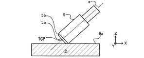
- FIG. 3A As shown in FIG. 3A, during dressing, the polishing tool 5 contacts the dressing surface 9a in the second posture while rotating around the tool rotation axis a.
- the second posture is a posture in which the tool rotation axis a of the polishing tool 5 is inclined with respect to a direction perpendicular to the dressing surface 9a (hereinafter simply referred to as a vertical direction). Determined based on the target shape.
- the target shape of the polishing tool 5 may be any shape as long as it can be molded against the dressing surface 9a or a dress surface perpendicular to the dressing surface 9a while rotating around the tool rotation axis a.
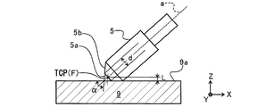
- the inclined surface 5b of the polishing tool 5 is shaved, and the height in the vertical direction where the end point 5a of the polishing tool 5 and the tool rotation axis a (hereinafter TCP: Tool center pint) is located decreases.
- TCP Tool center pint
- the position of the TCP when the dressing is completed and the polishing tool 5 has a target shape is the movement completion position F.
- the vertical separation distance L from the dressing surface 9a at the movement completion position F is defined as a diameter d of the end surface 5a of the polishing tool 5 and an angle between the dressing surface 9a and the inclined surface 5b as ⁇ .
- the movement completion position F is a position facing the dressing surface 9a (a position away from the dressing surface 9a).
- the separation distance L that becomes the movement completion position F is 0, and the movement completion position F is located on the dressing surface (in the surface of the dressing surface 9a). Will be.
- the molding control apparatus 1 always grasps the TCP coordinates of the polishing tool 5 in the spatial coordinates with the vertical direction as the Z-axis direction, and accurately grasps the Z-axis coordinates of the dressing surface 9a. Even if it is not completed, it is possible to accurately specify the Z-axis coordinate of the movement completion position F and increase the shape accuracy of the dressed polishing tool 5.
- specific processing of the molding control device 1 will be described in detail with reference to flowcharts.
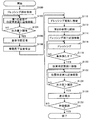
- FIG. 4 is a flowchart showing a processing flow of the molding control method.
- 5A to 5F are explanatory diagrams for explaining the movement of the polishing tool 5.
- FIG. 4 first, the dressing member 9 is held by the chuck device 6 (S100).
- the forming control device 1 performs polishing of the workpiece W and dressing of the polishing tool 5, respectively, the workpiece W and the polishing tool 5 are replaced.
- the chuck device 6 is Since the polishing tool 5 is held in advance, the holding step S100 is not performed.
- the robot motion control unit 7 specifies the position in the Z-axis direction in the first posture in which the tool rotation axis a of the polishing tool 5 is perpendicular to the position specifying surface 10.
- the polishing tool 5 is moved in the direction approaching the surface 10 (S102).
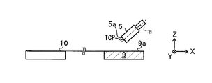
- the position specifying surface 10 is preferably a surface parallel to the dressing surface 9a, and has the same Z-axis coordinate as the dressing surface 9a, and is used to specify the exact coordinates of the movement completion position F.
- the position specifying surface 10 may not be parallel to the dressing surface 9a.
- the robot motion control unit 7 determines whether or not the output value output from the force detection output unit 8 exceeds a predetermined threshold (S104). If the output value does not exceed the threshold (NO in S104), the movement step The process returns to S102.
- the threshold value is set to a value larger than the upper limit value of the output value assumed to be output from the force detection output unit 8 due to noise even though the end surface 5a is not in contact with any surface.
- the robot motion control unit 7 stores the TCP Z-axis coordinate at that time as a reference position for deriving the movement completion position F (S106).
- TCP is a point on the tool rotation axis (on the tool rotation axis a) in contact with the position specifying surface 10 in the polishing tool 5 when the output value of the force detection output unit 8 exceeds the threshold value. .
- the robot motion control unit 7 derives an accurate Z-axis coordinate of the movement completion position F by adding the stored reference position and the vertical separation distance L from the dressing surface 9a of the movement completion position F.
- the coordinates of the movement completion position F are derived in combination with the X-axis coordinates and the Y-axis coordinates indicating the center of the dressing surface 9a stored in advance (S108).
- the robot operation control unit 7 moves the polishing tool 5 away from the position specifying surface 10 in the Z-axis direction, faces the dressing surface 9a of the dressing member 9, and moves to the movement completion position F as shown in FIG. It is moved to a location where TCP is located at the axis coordinate and the Y-axis coordinate (S110). Thereafter, as shown in FIG. 5D, the robot operation control unit 7 tilts the polishing tool 5 to the second posture around the TCP of the polishing tool 5 (S112). Note that it is not essential to move from the first posture to the second posture. It can also be moved to the second posture suddenly.
- the robot operation control unit 7 moves the polishing tool 5 in the Z-axis direction and in the direction close to the dressing surface 9a of the dressing member 9 while rotating the polishing tool 5 in the second posture (S114).
- dressing of the polishing tool 5 is performed as shown in FIG. 5E (S116).
- the robot motion control unit 7 displaces the polishing tool 5 from the first posture to the second posture and rotates in the second posture in the movement process from the reference position to the movement completion position F. It is made to contact
- the robot operation control unit 7 determines whether or not a preset condition is satisfied, for example (S118). If the condition is not satisfied (NO in S118), the dressing process step S116 is continued.
- the preset conditions are, for example, that the TCP Z-axis coordinate of the polishing tool 5 is included within a predetermined distance from the Z-axis coordinate of the movement completion position F, or that a predetermined time has elapsed.
- the predetermined distance and the predetermined time the following conditions are set every time the conditions are satisfied.
- the reason why the dressing is not performed until it is recognized from the beginning that the TCP has reached the movement completion position F is to avoid excessive dressing in view of the influence of noise such as dressing vibration.
- the robot motion control unit 7 stops the rotation while maintaining the polishing tool 5 in the second posture, and faces the position specifying surface 10 storing the reference position. (S120). Then, the robot motion control unit 7 moves the polishing tool 5 in the Z-axis direction and in the direction close to the position specifying surface 10 (S122), and the output value output from the force detection output unit 8 exceeds the threshold value. It is determined whether or not (S124).
- the threshold values in the output determination step S124 and the output determination step S104 described above are the same value, but individual values may be set.
- the process returns to the proximity movement step S122.
- the threshold value is exceeded (YES in S124)
- the inclined surface 5b of the polishing tool 5 comes into contact with the position specifying surface 10 as shown in FIG. 5F.
- the robot motion controller 7 derives a difference by subtracting the Z-axis coordinate of the movement completion position F from the Z-axis coordinate at that time (S126). Then, the robot motion control unit 7 determines whether or not the derived difference is included in the allowable range (S128).
- the allowable range YES in S128)
- the TCP of the polishing tool 5 moves to the movement completion position F, and it is determined that the dressing is completed, and the process is terminated. If it is determined that it is not included in the allowable range (NO in S128), the process returns to the movement step S110.
- the robot motion control unit 7 is based on the Z-axis coordinates (reference position) when the output value of the force detection output unit 8 exceeds the threshold value.
- the movement completion position F is specified. Therefore, the positional accuracy of the Z-axis coordinate of the movement completion position F is high, and the shape accuracy of the polishing tool 5 that has completed dressing can be increased.
- the Z-axis coordinate of the TCP can be accurately specified by the smooth position specifying surface 10 rather than the dressing surface 9a having a rough surface for performing dressing.
- the Z-axis coordinates are the same for the dressing surface 9a and the position specifying surface 10, but the Z-axis coordinates may be different.
- the robot operation control unit 7 specifies the movement completion position F in consideration of the difference between the Z-axis coordinates of the dressing surface 9a and the position specifying surface 10.
- the polishing tool 5 is once brought into contact with the position specifying surface 10 in a state where the rotation of the polishing tool 5 around the tool rotation axis a is stopped, and the dressing is determined depending on the position of the TCP at that time. Therefore, the robot motion control unit 7 can make the determination by eliminating the influence of noise such as vibration accompanying rotation.
- the reference position is determined by providing the position specifying surface 10, but depending on the surface roughness of the dressing surface 9 a and the shape accuracy required for the polishing tool 5, it may not be necessary to provide the position specifying surface 10. .
- modified examples effective in such a case will be described.
- the configuration of the molding control device 1 is substantially the same as the above-described embodiment except that the position specifying surface 10 is not provided, the same reference numerals are given and detailed description thereof is omitted.
- molding control method in a modification is demonstrated using a flowchart, about the process substantially equivalent to embodiment mentioned above, the same code
- FIG. 6 is a flowchart showing the flow of processing of the molding control method in the modification.
- the robot operation control unit 7 is in the first posture in which the tool rotation axis a of the polishing tool 5 is perpendicular to the dressing surface 9a, in the Z-axis direction and in the direction close to the dressing surface 9a.
- the polishing tool 5 is moved (S202).
- the robot operation control unit 7 does not have to specify the position of the dressing surface 9a accurately, as in the above-described embodiment, and the position of the TCP of the polishing tool 5 and the vertical direction of the dressing surface 9a are accurate. It is assumed that
- the robot motion control unit 7 specifies the movement completion position F by the separation distance L derived based on the above mathematical formula 1 (S204).
- the movement completion position F is simply specified by the separation distance L without specifying the Z-axis coordinate of the movement completion position F.
- the robot operation control unit 7 is, for example, a separation distance or more (separation distance L or more) in a vertical direction from the reference position in a separation direction that is opposite to the direction in which the polishing tool 5 approaches the dressing surface 9a. ) To move the polishing tool 5 (S206). This is not essential, and any distance that does not cause interference between the polishing tool 5 and the dresser may be used. In this moving process, the robot operation control unit 7 measures the moving distance of the polishing tool 5.
- the robot operation control unit 7 performs the processing from the inclination step S112 to the dressing processing step S116 after the polishing tool 5 has moved beyond the separation distance L from the reference position. Then, the robot operation control unit 7 performs the dressing and determines whether or not the polishing tool 5 has been moved in the direction close to the reference position by subtracting the separation distance L from the movement distance measured in the movement step S206. Determination is made (S208). If the movement of the difference distance has not been completed yet (NO in S208), the dressing processing step S116 is continued.
- the robot operation control unit 7 completes the movement to the movement completion position F while bringing the polishing tool 5 into contact with the dressing surface 9a while rotating in the second posture as described above. It is determined whether or not. Therefore, the processing time for moving to the position specifying surface 10 or returning to the dressing surface 9a can be shortened, and the completion of the movement to the movement completion position F can be detected at an early stage, possibly causing excessive dressing. Can be reduced.
- the robot operation control unit 7 grasps the TCP position of the polishing tool 5 in advance.
- the position of the tool rotation axis a of the polishing tool 5 and the dressing surface 9a or the position specifying surface 10 can be specified in advance even if the position of the TCP of the polishing tool 5 is not known. That's fine.
- the robot operation control unit 7 can accurately specify the TCP of the polishing tool 5 as the intersection of the tool rotation axis a and the dressing surface 9a (position specifying surface 10) in the reference storage step S106. In this case, even if the polishing tool 5 is worn out, a process for measuring the shape of the polishing tool 5 in advance can be omitted, and the work load can be reduced.
- the polishing tool 5 is made into a 2nd attitude
- FIG. The case of tilting has been described.
- the center for inclining the polishing tool 5 is not limited to TCP.
- the Z-axis coordinate of the TCP does not change due to the tilt of the polishing tool 5, and therefore a determination process as to whether or not the movement to the movement completion position F has been completed. It becomes possible to reduce the processing load concerning.
- the robot operation control unit 7 causes the polishing tool 5 to abut on the dressing surface 9a in the first posture, and is further separated from the dressing surface 9a by a separation distance L or more.
- the robot motion control unit 7 makes the polishing tool 5 abut on the dressing surface 9a in the first posture, and then is centered on the tool rotation axis a without being separated from the dressing surface 9a by a separation distance L or more.
- the polishing tool 5 may be rotated to be separated from the dressing surface 9a to the separation distance L while the polishing tool 5 is inclined in the second posture around the TCP. Even in this case, if dressing is performed until the TCP moves to the movement completion position F, the polishing tool 5 can be formed into a desired shape with high accuracy.
- the inclined surface 5b of the polishing tool 5 can be dressed with a more even force by once separating the polishing tool 5 from the separation distance L and then bringing the polishing tool 5 close to the dressing surface 9a.
- a program for causing the computer to execute as the robot operation control unit 7 and a recording medium such as a flexible disk, a magneto-optical disk, a ROM, an EPROM, an EEPROM, a CD, a DVD, and a BD on which the program is recorded are also provided. Is done.
- the program refers to data processing means described in an arbitrary language or description method.
- each process in the molding control method of the present specification does not necessarily have to be processed in time series in the order described as a flowchart.
- the present invention can be used for a molding control device, a molding control method, and a program.
- a Tool rotation axis d end face diameter, F movement completion position, L separation distance, W Work, ⁇ Angle between dressing surface and inclined surface, 1 Molding control device, 2 Robot arm, 2a joint, 2b section, 2c body, 3 Electric parts, 3a motor, 4 Tool holder, 5 Abrasive tool (molded member), 5a end face, 5b inclined surface, 6 Chuck device, 7 Robot motion controller, 7a Control PC, 7b Robot controller, 8 Force detection output section, 9 Dressing materials, 9a Dressing surface, 10 Positioning surface
Landscapes
- Engineering & Computer Science (AREA)
- Mechanical Engineering (AREA)
- Finish Polishing, Edge Sharpening, And Grinding By Specific Grinding Devices (AREA)
Abstract
成形制御装置(1)のロボット動作制御部(7)は、ドレッシング面(9a)と位置特定面(10)に対して、研磨工具(5)の工具回転軸が垂直となる第1の姿勢で、ドレッシング面(9a)もしくは位置特定面(10)に近接する方向に研磨工具(5)を移動させる(S102)。次いで、力検知出力部(8)から出力される出力値が閾値を超え研磨工具(5)がドレッシング面(9a)もしくは位置特定面(10)に当接した位置を基準位置とする(S106)。次に、基準位置に基づいて、ドレッシング面上もしくはドレッシング面(9a)に面する位置である移動完了位置まで研磨工具(5)を移動させる(S110)。基準位置から移動完了位置までの移動過程において、研磨工具(5)を、第1の姿勢から、ドレッシング面(9a)に対して工具回転軸が傾斜した第2の姿勢へと変位させるとともに(S112)、第2の姿勢で回転させながらドレッシング面(9a)に当接させる(S116)。
Description
本発明は、研磨工具を成形する成形制御装置、成形制御方法、および、プログラムに関する。
近年、産業用ロボットを利用した製造工程などの自動化が進んでいる。産業用ロボットは、力覚センサなどの検出値に応じてアーム(マニピュレータ)の動作を自動制御して、部材の組立や加工を行う。例えば、特許文献1に記載の構成の場合、アームに作用する力とトルクを検出する6軸力センサが設けられており、回転する研磨工具(砥石)に対し、アームに把持したワークを押し当てて研磨加工する。
そして、研磨工具のドレッシングが必要になると、ワークの代わりにドレッシング部材(砥石)をアームにセットして、ドレッシング部材を研磨工具に押し当て、研磨工具が所望の形状となるまでドレッシングを行う。研磨工具のドレッシング中、6軸力センサの出力値が設定値となるようにアームが制御されており、その設定値はコンピュータによってPID(Proportional Integral Derivative)制御される。
特許文献1では、研磨工具が所望の形状となったことをどのように判定してドレッシングを終了するのかが明記されていない。上記のように研磨工具のドレッシングを自動化する場合、研磨工具をドレッシング部材に当接させてから、研磨工具をドレッシング部材にどの位置まで押し付けてドレッシングするのかを正確に制御することが困難であった。
本発明は、このような課題に鑑み、ドレッシングにおいて高い形状精度を実現することが可能な成形制御装置、成形制御方法、および、プログラムを提供することを目的としている。
上記課題を解決するために、本発明の成形制御装置は、研磨工具を移動して、前記研磨工具を回転させながらドレッシング面に当接させて、該研磨工具を成形研磨するロボット動作制御部と、前記研磨工具に作用する荷重を示す出力値を出力する力検知出力部と、を備え、前記ロボット動作制御部は、前記ドレッシング面もしくは位置特定面に対して、前記研磨工具の工具回転軸が垂直となる第1の姿勢で、該ドレッシング面もしくは該位置特定面に近接する方向に該研磨工具を移動させ、前記力検知出力部から出力される出力値が閾値を超え、前記研磨工具が前記ドレッシング面もしくは前記位置特定面に当接した位置を基準位置とし、該基準位置に基づいて、該ドレッシング面上もしくは該ドレッシング面に面する位置である移動完了位置まで前記研磨工具を移動させ、前記基準位置から前記移動完了位置までの移動過程において、前記研磨工具を、前記第1の姿勢から、前記ドレッシング面に対して前記工具回転軸が傾斜した第2の姿勢へと変位させるとともに、該第2の姿勢で回転させながら該ドレッシング面に当接させることを特徴とする。
前記ロボット動作制御部は、前記力検知出力部から出力される出力値が前記閾値を超えたときに、前記研磨工具のうち、前記ドレッシング面もしくは前記位置特定面と接触した前記工具回転軸上の点を回動中心点として、該研磨工具を前記第2の姿勢に傾斜させてもよい。
前記ロボット動作制御部は、前記研磨工具を前記第1の姿勢で前記ドレッシング面に近接する方向に移動させるとともに、前記基準位置から、該ドレッシング面に対して垂直な方向への離隔距離によって、前記移動完了位置を特定し、前記力検知出力部から出力される出力値が前記閾値を超えると、前記基準位置から、前記近接する方向と逆方向である離隔方向に向けて、前記離隔距離以上に前記研磨工具を移動させるとともに、該移動過程において該研磨工具の移動距離を計測し、前記離隔距離以上に前記研磨工具が移動した後、前記研磨工具を、前記第1の姿勢から前記第2の姿勢へと変位させるとともに、該第2の姿勢で回転させながら、前記移動完了位置まで、前記近接する方向へと移動させてもよい。
前記ロボット動作制御部は、前記研磨工具を、前記第2の姿勢で回転させながら前記ドレッシング面に当接させつつ、前記移動完了位置までの移動が完了したか否かを判定させてもよい。
前記ロボット動作制御部は、前記研磨工具を、前記第2の姿勢に維持しつつ回転を停止し、前記ドレッシング面もしくは前記位置特定面のうち、前記基準位置を設定した方に近接する方向に該研磨工具を移動させ、前記力検知出力部から出力される出力値が前記閾値を超えた位置と前記基準位置との差分から、前記移動完了位置までの移動が完了したか否かを判定してもよい。
上記課題を解決するために、本発明の成形制御方法は、ドレッシング面もしくは位置特定面に対して、研磨工具の工具回転軸が垂直となる第1の姿勢で、該ドレッシング面もしくは該位置特定面に近接する方向に該研磨工具を移動させ、前記研磨工具に作用する荷重を示す出力値が閾値を超え、前記研磨工具が前記ドレッシング面もしくは前記位置特定面に当接した位置を基準位置とし、該基準位置に基づいて、該ドレッシング面上もしくは該ドレッシング面に面する位置である移動完了位置まで前記研磨工具を移動させ、前記基準位置から前記移動完了位置までの移動過程において、前記研磨工具を、前記第1の姿勢から、前記ドレッシング面に対して前記工具回転軸が傾斜した第2の姿勢へと変位させるとともに、該第2の姿勢で回転させながら該ドレッシング面に当接させることを特徴とする。
上記課題を解決するために、研磨工具に作用する荷重を示す出力値を出力する力検知出力部を備え、該研磨工具を移動して、該研磨工具を回転させながらドレッシング面に当接させて、該研磨工具を成形研磨するロボット動作制御部として機能するコンピュータを、前記ドレッシング面もしくは位置特定面に対して、前記研磨工具の工具回転軸が垂直となる第1の姿勢で、該ドレッシング面もしくは該位置特定面に近接する方向に該研磨工具を移動させ、前記力検知出力部から出力される出力値が閾値を超え、前記研磨工具が前記ドレッシング面もしくは前記位置特定面に当接した位置を基準位置とし、該基準位置に基づいて、該ドレッシング面上もしくは該ドレッシング面に面する位置である移動完了位置まで前記研磨工具を移動させ、前記基準位置から前記移動完了位置までの移動過程において、前記研磨工具を、前記第1の姿勢から、前記ドレッシング面に対して前記工具回転軸が傾斜した第2の姿勢へと変位させるとともに、該第2の姿勢で回転させながら該ドレッシング面に当接させる処理を実行させるためのプログラムが提供される。
上記本発明の装置、方法、および、プログラムによれば、ロボット動作制御部は、力検知出力部の出力値が閾値を超えたときの基準位置に基づいて、移動完了位置を特定する。そのため、移動完了位置の位置精度が高く、ドレッシングを完了した研磨工具の形状精度を高くすることが可能となる。
従って、本発明によって、ドレッシングにおいて高い形状精度を実現することが可能となる。
従って、本発明によって、ドレッシングにおいて高い形状精度を実現することが可能となる。
以下に添付図面を参照しながら、本発明の好適な実施形態について詳細に説明する。かかる実施形態に示す寸法、材料、その他具体的な数値等は、発明の理解を容易とするための例示にすぎず、特に断る場合を除き、本発明を限定するものではない。なお、本明細書および図面において、実質的に同一の機能、構成を有する要素については、同一の符号を付することにより重複説明を省略し、また本発明に直接関係のない要素は図示を省略する。
(成形制御装置1)(dressing control system)
図1は、ワークWの研磨加工時における成形制御装置1の全体構成を示す説明図である。図1に示すように、成形制御装置1は、ロボットアーム2を備える。ロボットアーム2は、複数の関節部2a(joint)を有し、関節部2aで連結される節部2b(Link)が関節部2aを回転中心として回転することが可能な構造となっている。電動部3は、例えばモータで構成され、それぞれの関節部2aに設けられ、本体2cに接続された電源の電力によって、関節部2aを中心に節部2bを回転させる動力を与える。
図1は、ワークWの研磨加工時における成形制御装置1の全体構成を示す説明図である。図1に示すように、成形制御装置1は、ロボットアーム2を備える。ロボットアーム2は、複数の関節部2a(joint)を有し、関節部2aで連結される節部2b(Link)が関節部2aを回転中心として回転することが可能な構造となっている。電動部3は、例えばモータで構成され、それぞれの関節部2aに設けられ、本体2cに接続された電源の電力によって、関節部2aを中心に節部2bを回転させる動力を与える。
ロボットアーム2の先端にも、電動部3の一部を構成するモータ3aが設けられている。また、モータ3aのシャフト先端には工具保持部4が設けられている。工具保持部4は、研磨工具5を保持しつつ、モータ3aによって回転可能に形成されている。研磨工具5は、例えば、砥石であり、研磨工具5の軸心がモータ3aのシャフトの回転軸の延長上に位置するように工具保持部4に保持される。
ロボット動作制御部7(Robot motion control unit)は、例えば、制御PC7a(control PC)、および、ロボットコントローラ7b(Robot controller)で構成される。制御PC7aは、電動部3の動作を制御するプログラムが書き込まれたコンピュータである。ロボットコントローラ7bは、制御PC7aから出力された制御信号に応じて電動部3に供給する電力を制御する。
そして、ロボット動作制御部7は、モータ3aを回転させながら、上記ロボットアーム2の移動を制御し、チャック装置6に保持されたワークWに、研磨工具5を押し当てることでワークWを成形研磨する。
力検知出力部8は、例えば、研磨工具5に作用する荷重を、ロボット動作制御部7の制御PC7aに出力する。制御PC7aは、力検知出力部8からの出力値に応じ、電動部3を制御することで、研磨工具5の姿勢制御を遂行する。
研磨工具5はワークWの研磨を行うごとに磨耗し、初期形状からの乖離が進むと、研磨の品質が維持できなくなる。そのため、研磨工具5のドレッシング(工具成形など)が必要となる。例えば、研磨処理を行ったワークWの数、研磨処理の累積時間などの指標が閾値を越えたことを契機として、ドレッシングが遂行される。
成形制御装置1は、ワークWの研磨を遂行するとともに、研磨工具5のドレッシングが必要となると、研磨工具5を工具保持部4から着脱することなく、ドレッシングを行うことができる。この場合、研磨工具5は、ドレッシングの対象となる被成形部材となる。また、成形制御装置1は、研磨工具5の元となる形状から研磨開始前の研磨工具5の形状を成形するドレッシングも遂行する。この場合、研磨工具5の元となる素材がドレッシングの対象となる被成形部材となる。以下では、研磨工具5と、研磨工具5の元となる素材を区別せず、単に研磨工具5と称す。
図2は、ドレッシング時における成形制御装置1の全体構成を示す説明図である。ドレッシングにおいて、チャック装置6にドレッシング部材9が保持される。ドレッシング部材9は、研磨工具5よりも固く、例えばダイヤモンド電着砥石などで構成される。
そして、ロボット動作制御部7は、電動部3を制御し、ドレッシング部材9のドレッシング面9aに対し、研磨工具5の軸心が傾斜した状態で、研磨工具5の軸心を工具回転軸として回転させながらドレッシング面9aに当接させ、ドレッシング面9aに垂直な方向に押圧し続けることで、研磨工具5をドレッシングする。
この場合、ドレッシング完了時、研磨工具5の工具回転軸のドレッシング面9aに対する傾斜角と、研磨工具5のドレッシング面9aに垂直な方向の位置によって、研磨工具5の形状が定まる。成形制御装置1は、例えば、制御PC7aによって計算された座標空間内における研磨工具5の位置および姿勢に基づいて、ドレッシングを制御する。
図3A,図3B,図3Cは、移動完了位置Fを説明するための説明図である。図3Aに示すように、ドレッシングの途中では、研磨工具5が工具回転軸aを中心として回転しながら、第2の姿勢でドレッシング面9aに当接する。
第2の姿勢は、研磨工具5の工具回転軸aが、ドレッシング面9aに垂直な方向(以下、単に垂直方向と称す)に対して傾斜した姿勢であって、その傾斜角は、研磨工具5の目標形状に基づいて定まる。ここで、研磨工具5の目標形状は、工具回転軸aを中心に回転しながらドレッシング面9a又はこれに垂直なドレス面に当てて成形できれば、どのような形状であってもよい。
ドレッシングが進むと、研磨工具5の傾斜面5bが削れ、研磨工具5の端面5aと工具回転軸aとの交点(以下、TCP:Tool center pint)が位置する垂直方向の高さが低くなる。そして、図3Bに示すように、ドレッシングが完了し、研磨工具5が目標形状となったときのTCPの位置が移動完了位置Fである。
図3Bに示すように、移動完了位置Fのドレッシング面9aからの垂直方向の離隔距離Lは、研磨工具5の端面5aの直径d、ドレッシング面9aと傾斜面5bのなす角をαとすると、以下の数式1で導出される。
L=d/2×cos(α/2)…数式(1)
L=d/2×cos(α/2)…数式(1)
また、図3Bに示す研磨工具5の形状が目標形状である場合、移動完了位置Fは、ドレッシング面9aに面する位置(ドレッシング面9aから離れた位置)となることとなる。なお、図3Cに示す研磨工具5の形状が目標形状である場合、移動完了位置Fとなる離隔距離Lは0となり、移動完了位置Fは、ドレッシング面上(ドレッシング面9aの面内)に位置することとなる。
本実施形態の成形制御装置1は、上記の垂直方向をZ軸方向とする空間座標において、研磨工具5のTCPの座標を常時把握しており、ドレッシング面9aのZ軸座標が 正確には把握できていなくとも、移動完了位置FのZ軸座標を正確に特定し、ドレッシングされた研磨工具5の形状精度を高めることが可能となる。以下、成形制御装置1の具体的な処理について、フローチャートを用いて詳述する。
(成形制御方法)
図4は、成形制御方法の処理の流れを示したフローチャートである。また図5A~図5Fは、研磨工具5の移動を説明するための説明図である。
図4に示すように、まず、チャック装置6にドレッシング部材9を保持させる(S100)。ここでは、成形制御装置1がワークWの研磨と研磨工具5のドレッシングをそれぞれ行うため、ワークWと研磨工具5の取り換えを行うが、成形制御装置がドレッシング専用装置である場合、チャック装置6は予め研磨工具5を保持しているため、保持ステップS100は行われない。
図4は、成形制御方法の処理の流れを示したフローチャートである。また図5A~図5Fは、研磨工具5の移動を説明するための説明図である。
図4に示すように、まず、チャック装置6にドレッシング部材9を保持させる(S100)。ここでは、成形制御装置1がワークWの研磨と研磨工具5のドレッシングをそれぞれ行うため、ワークWと研磨工具5の取り換えを行うが、成形制御装置がドレッシング専用装置である場合、チャック装置6は予め研磨工具5を保持しているため、保持ステップS100は行われない。
そして、ロボット動作制御部7は、図5Aに示すように、位置特定面10に対して、研磨工具5の工具回転軸aが垂直となる第1の姿勢で、Z軸方向であって位置特定面10に近接する方向に研磨工具5を移動させる(S102)。位置特定面10は、好ましくは、ドレッシング面9aと平行な面であって、ドレッシング面9aとZ軸座標が等しく、移動完了位置Fの正確な座標を特定するために用いられる。なお、位置特定面10はドレッシング面9aと平行でなくてもよい。
ロボット動作制御部7は、力検知出力部8から出力される出力値が予め定められた閾値を超えたか否かを判定し(S104)、閾値を超えていない場合(S104におけるNO)、移動ステップS102に処理を戻す。
そして、出力値が閾値を超えた場合(S104におけるYES)、図5Bに示すように、研磨工具5の端面5aが位置特定面10に当接したと判定する。ここで、閾値は、端面5aがいずれの面にも当接していないにもかかわらず、ノイズによって力検知出力部8から出力されると想定された出力値の上限値よりも大きい値とする。
すると、ロボット動作制御部7は、そのときのTCPのZ軸座標を、移動完了位置Fを導出するための基準位置として記憶する(S106)。また、TCPは、力検知出力部8の出力値が閾値を超えたとき、研磨工具5のうち、位置特定面10と接触した工具回転軸上(工具回転軸a上)の点となっている。
そして、ロボット動作制御部7は、記憶された基準位置と、移動完了位置Fのドレッシング面9aからの垂直方向の離隔距離Lを加算することで、移動完了位置Fの正確なZ軸座標を導出するとともに、予め記憶されていたドレッシング面9aにおける、例えば中央を示すX軸座標およびY軸座標の値と組み合わせて、移動完了位置Fの座標を導出する(S108)。
そして、ロボット動作制御部7は、研磨工具5を、位置特定面10からZ軸方向に離隔させ、図5Cに示すように、ドレッシング部材9のドレッシング面9aに面し、移動完了位置FのX軸座標およびY軸座標にTCPが位置する場所に移動させる(S110)。その後、ロボット動作制御部7は、図5Dに示すように、研磨工具5のTCPを中心として、研磨工具5を第2の姿勢に傾斜させる(S112)。
なお、第1の姿勢から第2の姿勢に移動することは必須ではない。いきなり第2の姿勢へ移動させることもできる。
なお、第1の姿勢から第2の姿勢に移動することは必須ではない。いきなり第2の姿勢へ移動させることもできる。
続いて、ロボット動作制御部7は、研磨工具5を第2の姿勢で回転させながら、Z軸方向であってドレッシング部材9のドレッシング面9aに近接する方向に移動させる(S114)。研磨工具5がドレッシング面9aに当接すると、図5Eに示すように、研磨工具5のドレッシングが行われる(S116)。
このように、ロボット動作制御部7は、基準位置から移動完了位置Fまでの移動過程において、研磨工具5を、第1の姿勢から第2の姿勢へと変位させるとともに、第2の姿勢で回転させながらドレッシング面9aに当接させる。
その後、ロボット動作制御部7は、例えば、予め設定された条件を満たしたか否かを判定する(S118)。条件を満たしていない場合(S118におけるNO)、ドレッシング処理ステップS116を継続する。
予め設定された条件は、例えば、研磨工具5のTCPのZ軸座標が、移動完了位置FのZ軸座標から所定距離内に含まれることや、所定時間が経過したことなどである。所定距離や所定時間は、条件を満たすごとに次の条件が設定されることとする。ここで、初めからTCPが移動完了位置Fに到達したと認識されるまで、ドレッシングを行わないのは、ドレッシングの振動などのノイズの影響を鑑み、ドレッシングのやり過ぎを回避するためである。
予め設定された条件を満たすと(S118におけるYES)、ロボット動作制御部7は、研磨工具5を、第2の姿勢に維持しつつ回転を停止し、基準位置を記憶した位置特定面10に面する位置に移動させる(S120)。そして、ロボット動作制御部7は、Z軸方向であって位置特定面10に近接する方向に、研磨工具5を移動させ(S122)、力検知出力部8から出力される出力値が閾値を超えたか否かを判定する(S124)。ここでは、当該出力判定ステップS124と上述した出力判定ステップS104における閾値は同じ値とするが、個別の値が設定されていてもよい。
閾値を超えていない場合(S124におけるNO)、近接移動ステップS122に処理を戻す。閾値を超えた場合(S124におけるYES)、図5Fに示すように、研磨工具5の傾斜面5bが位置特定面10に当接したこととなる。ロボット動作制御部7は、そのときのZ軸座標から、移動完了位置FのZ軸座標を減算して差分を導出する(S126)。そして、ロボット動作制御部7は、導出された差分が許容範囲に含まれるか否かを判定する(S128)。許容範囲に含まれる場合(S128におけるYES)、ドレッシング中に、研磨工具5のTCPが移動完了位置Fまで移動し、ドレッシングが完了したと判定し処理を終了する。許容範囲に含まれないと判定した場合(S128におけるNO)、移動ステップS110に処理を戻す。
上述したように、成形制御装置1および成形制御方法によれば、ロボット動作制御部7は、力検知出力部8の出力値が閾値を超えたときのZ軸座標(基準位置)に基づいて、移動完了位置Fを特定する。そのため、移動完了位置FのZ軸座標の位置精度が高く、ドレッシングを完了した研磨工具5の形状精度を高くすることが可能となる。
本実施形態では、位置特定面10に基づいて、研磨工具5のTCPが移動完了位置Fに到達したかを判定している。こうすることで、ドレッシングを遂行するために面が粗いドレッシング面9aよりも、平滑な位置特定面10によってTCPのZ軸座標を正確に特定できる。
また、本実施形態では、ドレッシング面9aと位置特定面10について、Z軸座標が同じとしたが、Z軸座標が異なっていてもよい。その場合、ロボット動作制御部7は、ドレッシング面9aと位置特定面10のZ軸座標の差を加味して、移動完了位置Fを特定することとする。
また、本実施形態では、一旦、研磨工具5の工具回転軸aを中心とした回転を停止した状態で、研磨工具5を位置特定面10に当接させ、そのときのTCPの位置によって、ドレッシングの完了を判定するため、ロボット動作制御部7は、回転に伴う振動などのノイズの影響を排除して判定することが可能となる。
上述した実施形態では、位置特定面10を設けて基準位置を定めたが、ドレッシング面9aの面粗さや研磨工具5に求められる形状精度によっては、位置特定面10を設ける必要がない場合もある。以下、このような場合に有効な変形例について説明する。ただし、成形制御装置1の構成については、位置特定面10を設けない点を除いて、上述した実施形態と実質的に同じであるため、同一の符号を付して詳細な説明は省略する。また、変形例における成形制御方法の処理の流れについてフローチャートを用いて説明するが、上述した実施形態と実質的に等しい処理については同一の符号を付して詳細な説明は省略する。
(変形例:成形制御方法)
図6は、変形例における成形制御方法の処理の流れを示したフローチャートである。図6において、ロボット動作制御部7は、ドレッシング面9aに対して、研磨工具5の工具回転軸aが垂直となる第1の姿勢で、Z軸方向であってドレッシング面9aに近接する方向に研磨工具5を移動させる(S202)。ここで、ロボット動作制御部7は、上述した実施形態と同様、ドレッシング面9aの位置は正確に特定しておらずともよく、研磨工具5のTCPの位置と、ドレッシング面9aの垂直方向は正確に特定しているものとする。
図6は、変形例における成形制御方法の処理の流れを示したフローチャートである。図6において、ロボット動作制御部7は、ドレッシング面9aに対して、研磨工具5の工具回転軸aが垂直となる第1の姿勢で、Z軸方向であってドレッシング面9aに近接する方向に研磨工具5を移動させる(S202)。ここで、ロボット動作制御部7は、上述した実施形態と同様、ドレッシング面9aの位置は正確に特定しておらずともよく、研磨工具5のTCPの位置と、ドレッシング面9aの垂直方向は正確に特定しているものとする。
そして、ロボット動作制御部7は、出力判定ステップS104、および、基準記憶ステップS106の後、上記数式1に基づいて導出される離隔距離Lによって移動完了位置Fを特定する(S204)。変形例においては、移動完了位置FのZ軸座標を特定せず、単に、離隔距離Lによって移動完了位置Fを特定したものとする。
そして、ロボット動作制御部7は、基準位置から、垂直方向であって、研磨工具5がドレッシング面9aに近接する方向と逆方向である離隔方向に向けて、例えば離隔距離以上(離隔距離L以上)に研磨工具5を移動させる(S206)。なおこれは必須ではなく、研磨工具5とドレッサーが干渉しない距離であればよい。この移動過程において、ロボット動作制御部7は、研磨工具5の移動距離を計測している。
続いて、ロボット動作制御部7は、基準位置から離隔距離L以上に研磨工具5が移動した後、傾斜ステップS112からドレッシング処理ステップS116までの処理が行われる。そして、ロボット動作制御部7は、ドレッシングを遂行しつつ、移動ステップS206において計測した移動距離から離隔距離Lを減算した差分距離、研磨工具5を基準位置に近接する方向に移動させたか否かを判定する(S208)。まだ差分距離の移動が完了していない場合(S208におけるNO)、ドレッシング処理ステップS116が継続される。
差分距離の移動が完了すると(S208におけるYES)、研磨工具5のTCPが移動完了位置Fに到達したこととなるため、ドレッシングが完了となり処理を終了する。
かかる変形例においても、成形制御装置1および成形制御方法によれば、上述した実施形態と同様、ドレッシングを完了した研磨工具5の形状精度を高くすることが可能となる。また、変形例においては、ロボット動作制御部7は、上記のように、研磨工具5を、第2の姿勢で回転させながらドレッシング面9aに当接させつつ、移動完了位置Fまでの移動が完了したか否かを判定している。そのため、位置特定面10に移動させたりドレッシング面9aに戻したりする分の処理時間を短縮できる上、移動完了位置Fまでの移動が完了したことを早期に検出でき、ドレッシングし過ぎとなる可能性を低減することができる。
ただし、変形例においても、上述した実施形態と同様、一旦、研磨工具5の工具回転軸aを 中心とした回転を停止してから、移動完了位置Fまでの移動が完了したか否かを判定してもよい。
上述した実施形態および変形例では、ロボット動作制御部7が、研磨工具5のTCPの位置を予め把握している場合について説明した。しかし、基準記憶ステップS106より前に、研磨工具5のTCPの位置がわかっていなくても、研磨工具5の工具回転軸aと、ドレッシング面9aもしくは位置特定面10の位置を予め特定していればよい。すると、ロボット動作制御部7は、基準記憶ステップS106において、工具回転軸aとドレッシング面9a(位置特定面10)との交点として研磨工具5のTCPを正確に特定できる。この場合、研磨工具5が磨耗するなどしていても、研磨工具5の形状計測などを予め行う処理を省略でき、作業負担を低減することが可能となる。
また、上述した実施形態および変形例では、研磨工具5のうち、ドレッシング面9aもしくは位置特定面10と接触した工具回転軸a上の点であるTCPを中心として研磨工具5を第2の姿勢に傾斜させる場合について説明した。しかし、研磨工具5を傾斜させる中心はTCPに限らない。ただし、上記のTCPを中心として研磨工具5を傾斜させることで、TCPのZ軸座標が、研磨工具5の傾斜によって変化しないため、移動完了位置Fまでの移動が完了したか否かの判定処理にかかる処理負荷を低減することが可能となる。
また、上述した変形例においては、ロボット動作制御部7は、研磨工具5を、第1の姿勢でドレッシング面9aに当接させ、さらに、ドレッシング面9aから離隔距離L以上、離隔させた後、TCPを中心として研磨工具5を第2の姿勢に傾斜させ、工具回転軸aを中心に研磨工具5を回転させ、ドレッシング面9aから離隔距離Lまで近接させる場合について説明した。
しかし、ロボット動作制御部7は、研磨工具5を、第1の姿勢でドレッシング面9aに当接させた後、ドレッシング面9aから離隔距離L以上、離隔させることなく、工具回転軸aを中心に研磨工具5を回転させ、TCPを中心として研磨工具5を第2の姿勢に傾斜させながら、ドレッシング面9aから離隔距離Lまで離隔させてもよい。この場合であっても、TCPが移動完了位置Fに移動するまでドレッシングが行われれば、研磨工具5を高精度に所望の形状とすることが可能となる。ただし、一旦、離隔距離L以上、研磨工具5を離隔させてからドレッシング面9aに近接させることで、研磨工具5の傾斜面5bをより均等な力でドレッシングすることができる。
さらに、コンピュータをロボット動作制御部7として実行させるプログラムや、そのプログラムを記録した、コンピュータで読み取り可能なフレキシブルディスク、光磁気ディスク、ROM、EPROM、EEPROM、CD、DVD、BD等の記録媒体も提供される。ここで、プログラムは、任意の言語や記述方法にて記述されたデータ処理手段をいう。
以上、添付図面を参照しながら本発明の好適な実施形態について説明したが、本発明はかかる実施形態に限定されないことは言うまでもない。当業者であれば、特許請求の範囲に記載された範疇において、各種の変更例または修正例に想到し得ることは明らかであり、それらについても当然に本発明の技術的範囲に属するものと了解される。
なお、本明細書の成形制御方法における各工程は、必ずしもフローチャートとして記載された順序に沿って時系列に処理する必要はない。
本発明は、成形制御装置、成形制御方法、および、プログラムに利用することができる。
a 工具回転軸、
d 端面の直径、
F 移動完了位置、
L 離隔距離、
W ワーク、
α ドレッシング面と傾斜面のなす角、
1 成形制御装置、
2 ロボットアーム、
2a 関節部、
2b 節部、
2c 本体、
3 電動部、
3a モータ、
4 工具保持部、
5 研磨工具(被成形部材)、
5a 端面、
5b 傾斜面、
6 チャック装置、
7 ロボット動作制御部、
7a 制御PC、
7b ロボットコントローラ、
8 力検知出力部、
9 ドレッシング部材、
9a ドレッシング面、
10 位置特定面
d 端面の直径、
F 移動完了位置、
L 離隔距離、
W ワーク、
α ドレッシング面と傾斜面のなす角、
1 成形制御装置、
2 ロボットアーム、
2a 関節部、
2b 節部、
2c 本体、
3 電動部、
3a モータ、
4 工具保持部、
5 研磨工具(被成形部材)、
5a 端面、
5b 傾斜面、
6 チャック装置、
7 ロボット動作制御部、
7a 制御PC、
7b ロボットコントローラ、
8 力検知出力部、
9 ドレッシング部材、
9a ドレッシング面、
10 位置特定面
Claims (7)
- 研磨工具を移動して、前記研磨工具を回転させながらドレッシング面に当接させて、該研磨工具を成形研磨するロボット動作制御部と、
前記研磨工具に作用する荷重を示す出力値を出力する力検知出力部と、
を備え、
前記ロボット動作制御部は、
前記ドレッシング面もしくは位置特定面に対して、前記研磨工具の工具回転軸が垂直となる第1の姿勢で、該ドレッシング面もしくは該位置特定面に近接する方向に該研磨工具を移動させ、
前記力検知出力部から出力される出力値が閾値を超え、前記研磨工具が前記ドレッシング面もしくは前記位置特定面に当接した位置を基準位置とし、該基準位置に基づいて、ドレッシング面上もしくは該ドレッシング面に面する位置である移動完了位置まで前記研磨工具を移動させ、
前記基準位置から前記移動完了位置までの移動過程において、前記研磨工具を、前記第1の姿勢から、前記ドレッシング面に対して前記工具回転軸が傾斜した第2の姿勢へと変位させるとともに、該第2の姿勢で回転させながら該ドレッシング面に当接させることを特徴とする成形制御装置。 - 前記ロボット動作制御部は、
前記力検知出力部から出力される出力値が前記閾値を超えたときに、前記研磨工具のうち、前記ドレッシング面もしくは前記位置特定面と接触した工具回転軸上の点をTCPとして、該研磨工具を前記第2の姿勢に傾斜させることを特徴とする請求項1に記載の成形制御装置。 - 前記ロボット動作制御部は、
前記研磨工具を前記第1の姿勢で前記ドレッシング面に近接する方向に移動させるとともに、前記基準位置から、該ドレッシング面に対して垂直な方向への離隔距離によって、前記移動完了位置を特定し、
前記力検知出力部から出力される出力値が前記閾値を超えると、前記基準位置から、前記近接する方向と逆方向である離隔方向に向けて、離隔距離以上に前記研磨工具を移動させるとともに、該移動過程において該研磨工具の移動距離を計測し、
前記離隔距離以上に前記研磨工具が移動した後、前記研磨工具を、前記第1の姿勢から前記第2の姿勢へと変位させるとともに、該第2の姿勢で回転させながら、前記移動完了位置まで、前記近接する方向へと移動させることを特徴とする請求項1または2に記載の成形制御装置。 - 前記ロボット動作制御部は、前記研磨工具を、前記第2の姿勢で回転させながら前記ドレッシング面に当接させつつ、前記移動完了位置までの移動が完了したか否かを判定することを特徴とする請求項1から3のいずれか1項に記載の成形制御装置。
- 前記ロボット動作制御部は、前記研磨工具を、前記第2の姿勢に維持しつつ回転を停止し、前記ドレッシング面もしくは前記位置特定面のうち、前記基準位置を設定した方に近接する方向に該研磨工具を移動させ、
前記力検知出力部から出力される出力値が前記閾値を超えた位置と前記基準位置との差分から、前記移動完了位置までの移動が完了したか否かを判定することを特徴とする請求項1から3のいずれか1項に記載の成形制御装置。 - ドレッシング面もしくは位置特定面に対して、研磨工具の工具回転軸が垂直となる第1の姿勢で、該ドレッシング面もしくは該位置特定面に近接する方向に該研磨工具を移動させ、
前記研磨工具に作用する荷重を示す出力値が閾値を超え、前記研磨工具が前記ドレッシング面もしくは前記位置特定面に当接した位置を基準位置とし、該基準位置に基づいて、ドレッシング面上もしくは該ドレッシング面に面する位置である移動完了位置まで前記研磨工具を移動させ、
前記基準位置から前記移動完了位置までの移動過程において、前記研磨工具を、前記第1の姿勢から、前記ドレッシング面に対して前記工具回転軸が傾斜した第2の姿勢へと変位させるとともに、該第2の姿勢で回転させながら該ドレッシング面に当接させることを特徴とする成形制御方法。 - 研磨工具に作用する荷重を示す出力値を出力する力検知出力部を備え、前記研磨工具を移動して、該研磨工具を回転させながらドレッシング面に当接させて、該研磨工具を成形研磨するロボット動作制御部として機能するコンピュータを、
前記ドレッシング面もしくは位置特定面に対して、前記研磨工具の工具回転軸が垂直となる第1の姿勢で、該ドレッシング面もしくは該位置特定面に近接する方向に該研磨工具を移動させ、
前記力検知出力部から出力される出力値が閾値を超え、前記研磨工具が前記ドレッシング面もしくは前記位置特定面に当接した位置を基準位置とし、該基準位置に基づいて、ドレッシング面上もしくは該ドレッシング面に面する位置である移動完了位置まで前記研磨工具を移動させ、
前記基準位置から前記移動完了位置までの移動過程において、前記研磨工具を、前記第1の姿勢から、前記ドレッシング面に対して前記工具回転軸が傾斜した第2の姿勢へと変位させるとともに、該第2の姿勢で回転させながら該ドレッシング面に当接させる処理を実行させるためのプログラム。
Priority Applications (1)
| Application Number | Priority Date | Filing Date | Title |
|---|---|---|---|
| PCT/JP2014/069644 WO2016013101A1 (ja) | 2014-07-25 | 2014-07-25 | 成形制御装置、成形制御方法、および、プログラム |
Applications Claiming Priority (1)
| Application Number | Priority Date | Filing Date | Title |
|---|---|---|---|
| PCT/JP2014/069644 WO2016013101A1 (ja) | 2014-07-25 | 2014-07-25 | 成形制御装置、成形制御方法、および、プログラム |
Publications (1)
| Publication Number | Publication Date |
|---|---|
| WO2016013101A1 true WO2016013101A1 (ja) | 2016-01-28 |
Family
ID=55162655
Family Applications (1)
| Application Number | Title | Priority Date | Filing Date |
|---|---|---|---|
| PCT/JP2014/069644 Ceased WO2016013101A1 (ja) | 2014-07-25 | 2014-07-25 | 成形制御装置、成形制御方法、および、プログラム |
Country Status (1)
| Country | Link |
|---|---|
| WO (1) | WO2016013101A1 (ja) |
Citations (4)
| Publication number | Priority date | Publication date | Assignee | Title |
|---|---|---|---|---|
| JPH04130155U (ja) * | 1991-05-23 | 1992-11-30 | 株式会社ナガセインテグレツクス | ドレツサ |
| JPH11216670A (ja) * | 1998-01-30 | 1999-08-10 | Toshiba Mach Co Ltd | 砥石成形システム及び砥石成形装置 |
| JP2006205281A (ja) * | 2005-01-26 | 2006-08-10 | Seiko Instruments Inc | ドレス装置、研削装置、ドレス方法、及び数値制御プログラム |
| JP2014144519A (ja) * | 2013-01-30 | 2014-08-14 | Ihi Corp | 成形制御装置、成形制御方法、および、プログラム |
-
2014
- 2014-07-25 WO PCT/JP2014/069644 patent/WO2016013101A1/ja not_active Ceased
Patent Citations (4)
| Publication number | Priority date | Publication date | Assignee | Title |
|---|---|---|---|---|
| JPH04130155U (ja) * | 1991-05-23 | 1992-11-30 | 株式会社ナガセインテグレツクス | ドレツサ |
| JPH11216670A (ja) * | 1998-01-30 | 1999-08-10 | Toshiba Mach Co Ltd | 砥石成形システム及び砥石成形装置 |
| JP2006205281A (ja) * | 2005-01-26 | 2006-08-10 | Seiko Instruments Inc | ドレス装置、研削装置、ドレス方法、及び数値制御プログラム |
| JP2014144519A (ja) * | 2013-01-30 | 2014-08-14 | Ihi Corp | 成形制御装置、成形制御方法、および、プログラム |
Similar Documents
| Publication | Publication Date | Title |
|---|---|---|
| JP6274561B2 (ja) | 回転砥石のドレッシング装置と方法 | |
| JP6084131B2 (ja) | 研磨システムおよびスポット溶接システム | |
| JP6323744B2 (ja) | 研磨ロボットとその制御方法 | |
| US20150034608A1 (en) | Grinding system and spot welding system | |
| JP5765557B2 (ja) | 加工ロボットの軌道追従装置と方法 | |
| JP5549330B2 (ja) | 加工ロボットとその加工制御方法 | |
| JP6089731B2 (ja) | 成形制御装置、成形制御方法、および、プログラム | |
| JP5534189B2 (ja) | 加工ロボットとその加工制御方法 | |
| JP6293477B2 (ja) | 研磨集塵システム | |
| JP6465404B2 (ja) | 基準面倣い治具とこれを用いる仕上げ加工装置及び方法 | |
| CN112823079A (zh) | 用于机器人涂漆修复中的多自由度柔性致动器力控制系统和方法 | |
| JP6347399B2 (ja) | 研磨ロボットとその軌道生成方法 | |
| JP7035369B2 (ja) | 加工方法 | |
| JP2019111589A (ja) | ドレッシング判定装置、ドレッシング判定システム、加工システム及びドレッシング判定方法 | |
| WO2016013101A1 (ja) | 成形制御装置、成形制御方法、および、プログラム | |
| JP2014155986A (ja) | 姿勢検知制御装置、研磨装置、および、姿勢検知制御方法 | |
| JP5251429B2 (ja) | 研削盤 | |
| CN109202721A (zh) | 研磨工艺的控制方法、研磨装置和机器人研磨系统 | |
| JP2011189417A (ja) | 加工ロボットとその重力補償方法 | |
| JP7158702B2 (ja) | 面取り研削装置 | |
| JP2018202582A (ja) | 加工方法及び加工装置 | |
| JP6977640B2 (ja) | 加工装置及び加工方法 | |
| JP7653945B2 (ja) | 加工装置 | |
| KR20230093865A (ko) | 이동형 몸체 로봇 기반 부품 피니싱 시스템 및 피니싱 공정방법 | |
| JP7052292B2 (ja) | 研削装置及び研削方法 |
Legal Events
| Date | Code | Title | Description |
|---|---|---|---|
| 121 | Ep: the epo has been informed by wipo that ep was designated in this application |
Ref document number: 14898230 Country of ref document: EP Kind code of ref document: A1 |
|
| NENP | Non-entry into the national phase |
Ref country code: DE |
|
| 122 | Ep: pct application non-entry in european phase |
Ref document number: 14898230 Country of ref document: EP Kind code of ref document: A1 |
|
| NENP | Non-entry into the national phase |
Ref country code: JP |