WO2016013094A1 - 排熱回収システム - Google Patents
排熱回収システム Download PDFInfo
- Publication number
- WO2016013094A1 WO2016013094A1 PCT/JP2014/069627 JP2014069627W WO2016013094A1 WO 2016013094 A1 WO2016013094 A1 WO 2016013094A1 JP 2014069627 W JP2014069627 W JP 2014069627W WO 2016013094 A1 WO2016013094 A1 WO 2016013094A1
- Authority
- WO
- WIPO (PCT)
- Prior art keywords
- heat recovery
- exhaust heat
- heater core
- cooling water
- passage
- Prior art date
- Legal status (The legal status is an assumption and is not a legal conclusion. Google has not performed a legal analysis and makes no representation as to the accuracy of the status listed.)
- Ceased
Links
Images








Classifications
-
- B—PERFORMING OPERATIONS; TRANSPORTING
- B60—VEHICLES IN GENERAL
- B60H—ARRANGEMENTS OF HEATING, COOLING, VENTILATING OR OTHER AIR-TREATING DEVICES SPECIALLY ADAPTED FOR PASSENGER OR GOODS SPACES OF VEHICLES
- B60H1/00—Heating, cooling or ventilating devices
- B60H1/02—Heating, cooling or ventilating devices the heat being derived from the propulsion plant
- B60H1/04—Heating, cooling or ventilating devices the heat being derived from the propulsion plant from cooling liquid of the plant
- B60H1/08—Heating, cooling or ventilating devices the heat being derived from the propulsion plant from cooling liquid of the plant from other radiator than main radiator
-
- Y—GENERAL TAGGING OF NEW TECHNOLOGICAL DEVELOPMENTS; GENERAL TAGGING OF CROSS-SECTIONAL TECHNOLOGIES SPANNING OVER SEVERAL SECTIONS OF THE IPC; TECHNICAL SUBJECTS COVERED BY FORMER USPC CROSS-REFERENCE ART COLLECTIONS [XRACs] AND DIGESTS
- Y02—TECHNOLOGIES OR APPLICATIONS FOR MITIGATION OR ADAPTATION AGAINST CLIMATE CHANGE
- Y02T—CLIMATE CHANGE MITIGATION TECHNOLOGIES RELATED TO TRANSPORTATION
- Y02T10/00—Road transport of goods or passengers
- Y02T10/10—Internal combustion engine [ICE] based vehicles
- Y02T10/12—Improving ICE efficiencies
Definitions
- the present invention relates to a vehicle exhaust heat recovery system including a front heater core and a rear heater core.
- JP 2006-105464A describes a configuration in which an exhaust heat recovery device is arranged in a return pipe from a rear heater core to an internal combustion engine as a vehicle exhaust heat recovery system including a front heater and a rear heater.
- the cooling water circuit in which the front heater core and the rear heater core are connected in parallel is used. Only will flow in. That is, of the cooling water flowing through the cooling water circuit including the heater core, the transmission oil cooler, and the radiator, only the cooling water after passing through the rear heater core contributes to exhaust heat recovery.
- the flow rate of the cooling water passing through the exhaust heat recovery device is small, the amount of heat recovery is limited in order to prevent boiling of the cooling water, so that it is necessary to improve the performance of the front heater and the rear heater. It is difficult to recover the amount of heat from the exhaust gas.
- an object of the present invention is to provide a heat recovery system capable of recovering a sufficient amount of heat to improve the performance of the front heater and the rear heater.
- exhaust heat provided with a cooling water circuit in which a front heater core and a rear heater core are connected in parallel, and an exhaust heat recovery unit that recovers heat of exhaust gas of the internal combustion engine into cooling water.
- a collection system is provided.
- the exhaust heat recovery device is connected in series to both the front heater core and the rear heater core.
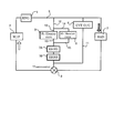
- FIG. 1 is a cooling water circuit diagram including an exhaust heat recovery system according to the first embodiment.
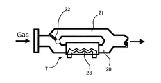
- FIG. 2 is a schematic configuration diagram of the exhaust heat recovery device.
- FIG. 3 is a cooling water circuit diagram as a comparative example.
- FIG. 4 is a piping diagram of the cooling water passage in the vehicle mounted state of the exhaust heat recovery system according to the first embodiment.
- FIG. 5A is a layout view of the heater core and the exhaust heat recovery device viewed from the side of the vehicle body.
- FIG. 5B is a cross-sectional view taken along the line VV in FIG. 5A.
- FIG. 6 is a piping diagram of a cooling water passage as an embodiment.
- FIG. 7 is a piping diagram of a cooling water passage as a comparative example.
- FIG. 8 is a cooling water circuit diagram including the exhaust heat recovery system according to the second embodiment.
- FIG. 9 is a piping diagram of the cooling water passage when the exhaust heat recovery system according to the second embodiment is mounted on a vehicle.
- FIG. 10 is a piping diagram of a cooling water passage as an embodiment.
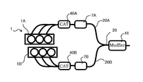
- FIG. 11 is an exhaust path diagram of the internal combustion engine to which the third embodiment is applied.
- FIG. 12 is a cooling water circuit diagram including the exhaust heat recovery system according to the third embodiment.
- FIG. 13 is a piping diagram of the cooling water passage when the exhaust heat recovery system according to the third embodiment is mounted on a vehicle.
- FIG. 14 is a piping diagram of a cooling water passage as another embodiment.
- FIG. 15 is a cooling water circuit diagram including the exhaust heat recovery system according to the fourth embodiment.
- FIG. 16 is a piping diagram of a cooling water passage when the exhaust heat recovery system according to the fourth embodiment is mounted on a vehicle.
- FIG. 17 is a piping diagram of a cooling water
- FIG. 1 is a cooling water circuit diagram of an internal combustion engine 1 including an exhaust heat recovery system according to the first embodiment.
- the cooling water supplied to the internal combustion engine 1 by the water pump 2 exchanges heat with the internal combustion engine 1 in a water jacket provided inside the internal combustion engine 1 and is discharged to the cooling water passage 9.
- the cooling water passage 9 is provided with a radiator 3 that releases the heat of the cooling water whose temperature has been increased by heat exchange with the internal combustion engine 1 into the atmosphere.
- the cooling water passage 9 is branched between the internal combustion engine 1 and the radiator 3 into a heater passage 10 and a transmission oil cooler passage 11.
- the heater passage 10 and the transmission oil cooler passage 11 merge on the downstream side of the exhaust heat recovery unit 7 described later, and further merge with the cooling water passage 9.
- the exhaust heat recovery unit 7 is shown as EHRS (ExhaustExHeat Recirculation System).
- a thermostat 8 is disposed at the junction of the cooling water passage 9, the heater passage 10, and the transmission oil cooler passage 11.
- the thermostat 8 is configured to open when the coolant temperature reaches a predetermined temperature. In the cooling water circuit of the present embodiment, only the cooling water from the heater passage 10 and the transmission oil cooler passage 11 flows to the water pump 2 when the thermostat 8 is closed.
- a water-cooled transmission oil cooler 4 for cooling the hydraulic fluid of the transmission is disposed in the transmission oil cooler passage 11.
- the heater passage 10 is provided with a front heater core 5 and a rear heater core 6 connected in parallel, and an exhaust heat recovery unit 7 connected in series to both of them. More specifically, the heater passage 10 includes a front heater core containing side passage 12 connected to the inlet of the front heater core 5 and a rear heater core containing side passage 14 connected to the inlet of the rear heater core 6. Branched. Then, the front heater core outlet side passage 13 connected to the outlet of the front heater core 5 and the rear heater core outlet side passage 15 connected to the outlet of the rear heater core 6 merge, and downstream from this junction. An exhaust heat recovery unit 7 is arranged.
- FIG. 2 is a diagram illustrating an example of the exhaust heat recovery device 7 that can be applied to the present embodiment.
- the exhaust heat recovery device 7 is interposed in the exhaust passage 20 of the internal combustion engine 1, and a heat exchange passage 23 is provided inside the exhaust heat recovery device 7 so as to be exposed to the exhaust gas.
- a heat exchange passage 23 is provided inside the exhaust heat recovery device 7 so as to be exposed to the exhaust gas.
- a bypass passage 21 is provided that branches from the exhaust passage 20, bypasses the exhaust heat recovery device 7, and joins the exhaust passage 20 again.
- a bypass valve 22 for adjusting the flow rate of the exhaust gas flowing through the bypass passage 21 is disposed at a branch portion between the exhaust passage 20 and the bypass passage 21.
- the exhaust heat recovery device 7 is disposed downstream from the confluence of the exhaust passages of the cylinders.
- the exhaust heat recovery unit 7 is disposed downstream from the junction of the exhaust passages of both banks.
- the cooling water exiting the internal combustion engine 1 flows through the cooling water passage 9, the heater passage 10 branched from the cooling water passage 9, and the transmission oil cooler passage 11.
- the cooling water flowing through the heater passage 10 branches and flows into the front heater core 5 and the rear heater core 6, joins on the downstream side of the front heater core 5 and the rear heater core 6, and then enters the exhaust heat recovery unit 7. Inflow.
- the cooling water exiting the exhaust heat recovery unit 7 merges with the cooling water from the transmission oil cooler passage 11, passes through the thermostat 8, and flows into the internal combustion engine 1 again through the water pump 2.
- the thermostat 8 is opened, the cooling water that has passed through the radiator 3 is merged with the cooling water that has passed through the exhaust heat recovery device 7.
- FIG. 3 shows, as a comparative example, a cooling water circuit including the heat recovery system described in JP2006-105464A described above in the same manner as FIG.
- the exhaust heat recovery device 7 is arranged downstream of the junction of the front heater core outlet passage 13 and the rear heater core outlet passage 15 in FIG.
- FIG. 3 there is a difference that it is arranged in the rear heater core outlet passage 15. That is, while the cooling water that has passed through the front heater core 5 and the cooling water that has passed through the rear heater core 6 flow into the exhaust heat recovery device 7 of the present embodiment, the heat recovery device 7 of the comparative example includes There is a difference that only the cooling water that has passed through the rear heater core 6 flows.
- the flow rate of the cooling water passing through the exhaust heat recovery unit 7 is increased as compared with the configuration of FIG. 1, and the amount of exhaust heat recovery is increased. Further, the configuration of the present embodiment makes it difficult for boiling water to boil due to an increase in the flow rate of cooling water as compared with the configuration of FIG.
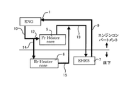
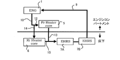
- FIG. 4 is a piping diagram of the cooling water passage when the exhaust heat recovery system in this embodiment is mounted on a vehicle.
- the water pump 2 and the thermostat 8 are omitted. Further, although the front heater core 5 is actually disposed in the vehicle compartment, here, since attention is paid to the piping between the engine compartment and the floor, it is described on the engine compartment side for convenience. The same applies to FIGS. 6, 9, 10, 13, 14, 16, and 17 described later.
- FIG. 5A is a diagram schematically showing the arrangement of the internal combustion engine 1, the front heater core 5, the rear heater core 6, and the exhaust heat recovery device 7 when viewed from the side of the vehicle body.
- FIG. 5B is a cross-sectional view taken along the line VV in FIG. 5A.
- the exhaust heat recovery device 7 is disposed under the floor, and the rear heater core outlet side passage 15 and the front heater core outlet side passage 13 merge under the floor.
- the three pipes of the rear heater core entering side passage 14 branched from the cooling water passage 9, the front heater core outlet side passage 13, and the cooling water passage 9 returning from the exhaust heat recovery device 7 to the internal combustion engine 1 are engine. It will straddle the compartment and under the floor.
- the cooling water passages 9, 13, 14, and 15 are accommodated in the floor tunnel 30 under the floor.
- the floor tunnel 30 also houses the exhaust pipe 31 and the propeller shaft 32, and the cooling water passage accommodated in the floor tunnel 30 includes the exhaust pipe 31 and It arrange
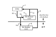
- FIG. 6 is a piping diagram when the junction point of the rear heater core outlet passage 15 and the front heater core outlet passage 13 of FIG. 4 is moved into the engine compartment.
- FIG. 7 is a piping diagram when the exhaust heat recovery unit 7 is not provided.
- the piping extending between the engine compartment and the floor is provided with a rear heater core containing side passage 14 and a cooling water passage returning from the rear heater core 6 to the internal combustion engine 1.
- the piping extending between the engine compartment and the underfloor includes a rear heater core containing side passage 14, a rear heater core outlet side passage 15, a front heater core outlet side passage 13, and a heat recovery unit.
- Four cooling water passages 9 return from the engine 7 to the internal combustion engine 1.
- the piping extending between the engine compartment and the underfloor includes the rear heater core entrance side passage 14 branched from the cooling water passage 9 and the front heater core exit side passage 13 as described above. And a cooling water passage 9 returning from the exhaust heat recovery device 7 to the internal combustion engine 1.
- the piping length of the rear heater core outlet passage 15 is from the rear heater core 6 to the engine compartment in the configuration of FIG. 6, whereas in the configuration of this embodiment, near the exhaust heat recovery unit 7 under the floor. Is enough. That is, according to the present embodiment, it is possible to suppress an increase in the piping path length accompanying the addition of the exhaust heat recovery unit 7 and to suppress a decrease in heater performance.
- the exhaust heat recovery system of the present embodiment includes a cooling water circuit in which a front heater core 5 and a rear heater core 6 are connected in parallel, and an exhaust heat recovery device 7 that recovers heat of exhaust gas of the internal combustion engine 1 into cooling water. And comprising.
- the exhaust heat recovery device 7 is connected in series to both the front heater core 5 and the rear heater core 6.
- the front heater core 5 is disposed in the engine compartment
- the rear heater core 6 is disposed under the floor of the vehicle body
- the cooling water passages 12 and 13 in which the front heater core 5 is disposed and the rear heater.
- a branch point or junction with the cooling water passages 14 and 15 in which the core 6 is disposed is under the floor of the vehicle body.
- the exhaust heat recovery device 7 is located downstream of the junction of the cooling water passage 13 where the front heater core 5 of the cooling water circuit is arranged and the cooling water passage 15 where the rear heater core 6 is arranged. Placed in.
- the exhaust heat recovery unit 7 is connected in series only to the rear heater core 6 as shown in FIG. 3 and is not connected to the front heater core 5 in series. Since the flow rate of the coolant passing through 7 increases, the temperature drop when the coolant joins with the coolant from the transmission oil cooler passage 11 or the like can be suppressed.
- FIG. 8 is a cooling water circuit diagram of the internal combustion engine 1 including the exhaust heat recovery system according to the second embodiment. The arrangement of the exhaust heat recovery device 7 is different from FIG.
- the exhaust heat recovery device 7 of the present embodiment is disposed on the upstream side of the branch point between the front heater core containing side passage 12 and the rear heater core containing side passage 14 of the heater passage 10.
- the cooling water whose temperature has increased in the exhaust heat recovery unit 7 is reduced in temperature by the merge with the cooling water that has passed through the transmission oil cooler passage 11 and the radiator 3 before the front heater core 5 and the rear heater core 6. Flow into.
- FIG. 9 is a piping diagram of the coolant passage in the vehicle mounted state of the exhaust heat recovery system in the present embodiment.
- the rear heater core 6 and the exhaust heat recovery device 7 are connected by a rear heater core containing side passage 14 that passes only under the floor without passing through the engine compartment.
- the three pipes of the heater passage 10, the front heater core entrance passage 12, and the rear heater core exit passage 15 straddle the engine compartment and the underfloor.
- the pipe connecting the exhaust heat recovery device 7 and the rear heater core 6 is completed only under the floor, as shown in FIG. As compared with the configuration in which the rear heater core containing side passage 14 branches, the pipe length can be shortened.
- the present embodiment as in the first embodiment, it is possible to suppress the deterioration of the layout of the piping path due to the addition of the exhaust heat recovery device 7. Moreover, similarly to 1st Embodiment, the increase in the piping path length accompanying the extension of the exhaust heat recovery device 7 can be suppressed, and the fall of heater performance can be suppressed.
- the exhaust heat recovery device 7 is disposed upstream from the branch point between the front heater core side passage 12 and the rear heater core side passage 14.
- the cooling water whose temperature has risen in the exhaust heat recovery unit 7 is reduced in temperature by the merging with the cooling water that has passed through the transmission oil cooler passage 11 and the radiator 3, before the front heater core 5 and the rear heater core. Since it flows into 6, the heater performance can be improved.
- the third embodiment is different from the first and second embodiments in that it includes a plurality of exhaust heat recovery devices.
- first exhaust heat recovery unit 7A when it is necessary to distinguish a plurality of exhaust heat recovery units, they are referred to as “first exhaust heat recovery unit 7A” and “second exhaust heat recovery unit 7B”. It is set as the collection device 7 ”.
- FIG. 11 is an exhaust path diagram of the internal combustion engine system including the exhaust heat recovery system according to the present embodiment.
- the internal combustion engine 1 is a V-type internal combustion engine including a first bank 1A and a second bank 1B, and the first exhaust passage 20A into which the exhaust passages from the cylinders of the first bank 1A are joined from the upstream side.
- a first exhaust catalyst 40A and a first exhaust heat recovery unit 7A are arranged.
- the second exhaust catalyst 40B and the second exhaust heat recovery device 7B are arranged in the second exhaust passage 20B where the exhaust passages from the respective cylinders of the second bank 1B join.
- the first exhaust passage 20A and the second exhaust passage 20B join together on the downstream side of the first exhaust heat recovery device 7A and the second exhaust heat recovery device 7B to form the exhaust passage 20.
- a muffler 41 for silencing is arranged in the exhaust passage 20.
- FIG. 12 is a cooling water circuit diagram of the internal combustion engine 1 including the exhaust heat recovery system according to the present embodiment.
- the first exhaust heat recovery unit 7A is connected in series to the downstream side of the front heater core 5
- the second exhaust heat recovery unit 7B is connected in series to the downstream side of the rear heater core 6,
- the heat recovery device outlet side passage 42 and the second exhaust heat recovery device outlet side passage 43 merge.
- FIG. 13 is a piping diagram of the cooling water passage when the exhaust heat recovery system according to the present embodiment is mounted on a vehicle.
- the first exhaust heat recovery device outlet side passage 42 and the second exhaust heat recovery device outlet side passage 43 merge under the floor.
- the cooling water passage 9 in which the rear heater core entering side passage 14, the front heater core exit side passage 13, and the first exhaust heat recovery device exit side passage 42 and the second exhaust heat recovery device exit side passage 43 merge is formed. It will straddle the engine compartment and the underfloor. That is, there are three pipes that straddle the engine compartment and the underfloor as in the first and second embodiments.
- the exhaust heat recovery unit 7 is disposed in each of the exhaust passages 20A and 20B from each bank of the V-type internal combustion engine 1, and the first exhaust heat recovery unit 7A is used as the front heater core 5.
- the second exhaust heat recovery unit 7B is connected to the rear heater core 6 in series.
- the fourth embodiment includes two exhaust heat recovery units 7 as in the third embodiment. That is, as shown in FIG. 11, the exhaust heat recovery devices 7A and 7B are arranged in the exhaust paths 20A and 20B from the banks 1A and 1B of the V-type internal combustion engine 1, respectively.
- the cooling water circuit for connecting the front heater core 5 and the rear heater core 6 to the two exhaust heat recovery devices 7A and 7B is different from the third embodiment.
- the difference from the third embodiment will be mainly described.
- FIG. 15 is a cooling water circuit diagram of the internal combustion engine 1 including the exhaust heat recovery system according to the present embodiment.
- the first exhaust heat recovery unit 7 ⁇ / b> A is disposed downstream of the junction of the front heater core outlet side passage 13 and the rear heater core outlet side passage 15.
- the second exhaust heat recovery unit 7B is arranged in series on the downstream side of the first exhaust heat recovery unit 7A.
- FIG. 16 is a piping diagram of the cooling water passage when the exhaust heat recovery system in this embodiment is mounted on a vehicle.
- the front heater core outlet passage 13 and the rear heater core outlet passage 15 merge under the floor.
- the rear heater core entrance side passage 14, the front heater core exit side passage 13, and the cooling water passage 9 on the downstream side of the second exhaust heat recovery device 7B straddle the engine compartment and the underfloor. That is, there are three pipes that straddle the engine compartment and the underfloor as in the first embodiment, the second embodiment, and the third embodiment.
- the first exhaust heat recovery device 7A and the second exhaust heat recovery device 7B disposed in each of the exhaust passages 20A and 20B from each bank of the V-type internal combustion engine 1 are replaced with the front heater.
- the core outlet side passage 13 and the rear heater core outlet side passage 15 are connected in series downstream from the junction.
Landscapes
- Engineering & Computer Science (AREA)
- Chemical & Material Sciences (AREA)
- Combustion & Propulsion (AREA)
- Physics & Mathematics (AREA)
- Thermal Sciences (AREA)
- Mechanical Engineering (AREA)
- Air-Conditioning For Vehicles (AREA)
Abstract
排熱回収システムは、フロントヒーター用のヒーターコアと、リアヒーター用のヒーターコアとが並列に接続される冷却水回路と、内燃機関の排気ガスとの熱交換によって、排気ガスの熱を冷却水に回収するよう構成された排熱回収器とを備える。そして、この排熱回収システムでは、排気ガスの熱をより多く回収するために、排熱回収器がフロントヒーターコア及びリアヒーターコアのいずれに対しても、直列接続となるように配置されている。
Description
本発明は、フロントヒーターコア及びリアヒーターコアを備える車両用の排熱回収システムに関する。
車両のヒーター性能の向上や、冷機始動時における冷却水の早期昇温等を目的として、排気ガスの熱(以下、排熱ともいう)を冷却水に回収する排熱回収システムが知られている。そして、JP2006-105464Aには、フロントヒーターとリアヒーターとを備える車両の排熱回収システムとして、リアヒーターコアから内燃機関への戻り配管に排熱回収器を配置する構成が記載されている。
しかしながら、上記文献に記載の排熱回収システムでは、フロントヒーターコアとリアヒーターコアとが並列に接続される冷却水回路となっているため、排熱回収器にはリアヒーターコアを通過した冷却水だけが流入することとなる。すなわち、ヒーターコア、変速機用のオイルクーラ、及びラジエータを含む冷却水回路を流れる冷却水のうち、排熱回収に寄与するのはリアヒーターコア通過後の冷却水だけである。このように排熱回収器を通過する冷却水流量が少ない構成では、冷却水の沸騰を防止するために熱回収量が制限されるので、フロントヒーター及びリアヒーターの性能を向上させるために必要な熱量を排気ガスから回収することが難しい。
そこで本発明では、フロントヒーター及びリアヒーターの性能を向上させるのに十分な熱量を回収し得る熱回収システムを提供することを目的とする。
本発明のある態様によれば、フロントヒーターコアとリアヒーターコアとが並列に接続される冷却水回路と、内燃機関の排気ガスの熱を冷却水に回収する排熱回収器とを備える排熱回収システムが提供される。この排熱回収システムでは、排熱回収器がフロントヒーターコア及びリアヒーターコアのいずれに対しても直列に接続されている。
以下、添付図面を参照しながら本発明の実施形態について説明する。
(第1実施形態)
図1は、第1実施形態にかかる排熱回収システムを含む、内燃機関1の冷却水回路図である。
図1は、第1実施形態にかかる排熱回収システムを含む、内燃機関1の冷却水回路図である。
冷却水は、ウォータポンプ2により内燃機関1に供給された冷却水は、内燃機関1の内部に設けたウォータジャケットにおいて内燃機関1と熱交換し、冷却水通路9へ排出される。冷却水通路9には、ウォータポンプ2の他に、内燃機関1との熱交換で温度上昇した冷却水の熱を大気中に放出するラジエータ3が配置されている。
また、冷却水通路9は、内燃機関1とラジエータ3との間で、ヒーター用通路10と変速機オイルクーラ用通路11とに分岐している。ヒーター用通路10と変速機オイルクーラ用通路11は、後述する排熱回収器7の下流側で合流し、さらに冷却水通路9に合流する。なお、図中では排熱回収器7をEHRS(Exhaust Heat Recirculation System)と示している。
冷却水通路9と、ヒーター用通路10及び変速機オイルクーラ用通路11との合流点にはサーモスタット8が配置されている。サーモスタット8は、冷却水温が所定温度になると開弁する構成となっている。本実施形態の冷却水回路は、サーモスタット8が閉弁している状態では、ヒーター用通路10及び変速機オイルクーラ用通路11からの冷却水のみがウォータポンプ2へ流れるようになっている。
変速機オイルクーラ用通路11には、変速機の作動油を冷却するための、水冷式の変速機オイルクーラ4が配置されている。
ヒーター用通路10には、並列に接続されるフロントヒーターコア5及びリアヒーターコア6と、これらのいずれに対しても直列に接続される排熱回収器7と、が配置されている。より具体的には、ヒーター用通路10が、フロントヒーターコア5の入口に接続されるフロントヒーターコア入り側通路12と、リアヒーターコア6の入口に接続されるリアヒーターコア入り側通路14とに分岐している。そして、フロントヒーターコア5の出口に接続されるフロントヒーターコア出側通路13と、リアヒーターコア6の出口に接続されるリアヒーターコア出側通路15とが合流し、この合流点より下流側に排熱回収器7が配置されている。
図2は、本実施形態に適用し得る排熱回収器7の一例を示す図である。
排熱回収器7は、内燃機関1の排気通路20に介装されており、内部には排気ガスにさらされるように熱交換用通路23が設けられている。この熱交換用通路23に冷却水を流すと、冷却水と排気ガスとの間で熱交換が行われ、排気ガスの熱が冷却水に回収される。
内燃機関1の排気系路には、排気通路20から分岐して、排熱回収器7を迂回して再び排気通路20に合流するバイパス通路21が設けられている。排気通路20とバイパス通路21との分岐部には、バイパス通路21を流れる排気ガス流量を調整するためのバイパスバルブ22が配置されている。
バイパスバルブ22によってバイパス通路21の排気ガス流量を低減させると、排熱回収器7に流入する排気ガス流量が増大するので、冷却水に回収できる熱量(排熱回収量)も増大する。一方、バイパスバルブ22によってバイパス通路21を通過する排気ガス流量を低減させると、排熱回収量を低減できる。
なお、内燃機関1が直列内燃機関の場合には、排熱回収器7は各気筒の排気通路の合流点より下流側に配置される。一方、内燃機関1がV型内燃機関や水平対向内燃機関の場合には、排熱回収器7は両バンクの排気通路の合流点より下流側に配置される。
上述した構成の排熱回収システムでは、内燃機関1を出た冷却水は冷却水通路9、及び冷却水通路9から分岐しているヒーター用通路10及び変速機オイルクーラ用通路11を流れる。
ヒーター用通路10を流れる冷却水は、分岐してフロントヒーターコア5とリアヒーターコア6とに流入し、フロントヒーターコア5及びリアヒーターコア6の下流側で合流してから排熱回収器7に流入する。排熱回収器7を出た冷却水は、変速機オイルクーラ用通路11からの冷却水と合流してから、サーモスタット8を通過し、ウォータポンプ2を介して再び内燃機関1に流入する。なお、サーモスタット8が開弁している場合は、排熱回収器7を通過した冷却水に、ラジエータ3を通過した冷却水も合流する。
上記のサイクルにおいて、排熱回収器7による排熱回収を行えば、温度上昇した冷却水がウォータポンプ2、内燃機関1を通過してフロントヒーターコア5、リアヒーターコア6に流入するので、ヒーター性能が向上する。
ここで、ヒーター性能の向上について、より詳細に説明する。
図3は、比較例として、上述したJP2006-105464Aに記載されている熱回収システムを含む冷却水回路を図1と同様に表したものである。
図3と図1とを対比すると、排熱回収器7が、図1ではフロントヒーターコア出側通路13とリアヒーターコア出側通路15との合流点よりも下流側に配置されているのに対し、図3ではリアヒーターコア出側通路15に配置されているという相違点がある。すなわち、本実施形態の排熱回収器7にはフロントヒーターコア5を通過した冷却水とリアヒーターコア6を通過した冷却水とが流入するのに対し、比較例の熱回収器7には、リアヒーターコア6を通過した冷却水しか流入しない、という相違点がある。
排熱回収器7を通過する冷却水流量が少ないほど、回収可能な熱量が少なくなる。そのうえ、冷却水流量が少ないほど冷却水は沸騰し易くなるので、沸騰防止のための排熱回収量の上限が低くなる。
したがって、本実施形態の構成は、図1の構成に比べて排熱回収器7を通過する冷却水流量が多くなり、排熱回収量が増大する。また、本実施形態の構成は、図1の構成に比べて冷却水流量が多くなることにより冷却水が沸騰し難くなるので、排熱回収量の上限が高くなる。
次に、上述した熱回収システムを車両に搭載する場合の、冷却水の配管について説明する。
図4は、本実施形態における排熱回収システムの、車両搭載状態での冷却水通路の配管図である。
なお、ウォータポンプ2、サーモスタット8は省略してある。また、フロントヒーターコア5は実際には車室内に配置されるが、ここではエンジンコンパートメントと床下との間の配管に着目するので、便宜上、エンジンコンパートメント側に記載してある。後述する図6、9、10、13、14、16、17についても同様である。
図5Aは、車体の側方から見た場合の、内燃機関1、フロントヒーターコア5、リアヒーターコア6、及び排熱回収器7の配置を模式的に表した図である。図5Bは、図5AのV-V線に沿った断面図である。
図4、図5Aに示すように、排熱回収器7は床下に配置されており、リアヒーターコア出側通路15とフロントヒーターコア出側通路13とが床下で合流している。その結果、冷却水通路9から分岐したリアヒーターコア入り側通路14、フロントヒーターコア出側通路13、及び排熱回収器7から内燃機関1へ戻る冷却水通路9、の3本の配管がエンジンコンパートメントと床下とをまたぐこととなる。
図5A、図5Bに示すように、冷却水通路9、13、14、15は、床下ではフロアトンネル30に収容される。図5Aでは省略しているが、図5Bに示すようにフロアトンネル30には、排気管31及びプロペラシャフト32も収容されており、フロアトンネル30に収容される冷却水通路は、排気管31やプロペラシャフト32と干渉しないように配置されている。
ところで、エンジンコンパートメントと床下とにまたがる冷却水の配管経路を設定する際には、冷却水通路と他の部品とが干渉しないように設定する必要がある。したがって、エンジンコンパートメントと床下とにまたがる配管の本数が多くなるほど、経路の設定が困難になる。つまり、配管経路のレイアウト性が悪化する。また、配管の経路が長くなるほど配管表面からの放熱量が多くなりヒーター性能が低下するので、経路の長さは短い方が望ましい。
ここで、本実施形態の排熱回収システムの配管経路のレイアウト性及び経路長について、図6、図7に示す構成と比較して説明する。
図6は、図4のリアヒーターコア出側通路15とフロントヒーターコア出側通路13との合流点を、エンジンコンパートメント内に移動した場合の配管図である。図7は、排熱回収器7を備えない場合の配管図である。
図7に示すように、排熱回収器7を備えない構成では、エンジンコンパートメントと床下とにまたがる配管は、リアヒーターコア入り側通路14と、リアヒーターコア6から内燃機関1に戻る冷却水通路9の2本である。そして、図6に示す構成では、エンジンコンパートメントと床下とにまたがる配管は、リアヒーターコア入り側通路14と、リアヒーターコア出側通路15と、フロントヒーターコア出側通路13と、排熱回収器7から内燃機関1へ戻る冷却水通路9、の4本である。
一方、図5に示す本実施形態の構成では、エンジンコンパートメントと床下とにまたがる配管は、上述したように冷却水通路9から分岐したリアヒーターコア入り側通路14と、フロントヒーターコア出側通路13と、排熱回収器7から内燃機関1へ戻る冷却水通路9、の3本である。
つまり、図6のような配管経路にすると、排熱回収器7の増設に伴ってエンジンコンパートメントと床下とにまたがる配管が2本増加するのに対し、本実施形態によれば1本の増加で済む。これにより、排熱回収器7の増設に伴う配管経路のレイアウト性の悪化を抑制できる。
また、リアヒーターコア出側通路15の配管長さは、図6の構成ではリアヒーターコア6からエンジンコンパートメント内までとなるのに対し、本実施形態の構成では床下の排熱回収器7の近くまでで足りる。つまり、本実施形態によれば、排熱回収器7の増設に伴う配管経路長の増大を抑制して、ヒーター性能の低下を抑制することができる。
次に、上述した本実施形態による作用効果についてまとめる。
本実施形態の排熱回収システムは、フロントヒーターコア5とリアヒーターコア6とが並列に接続される冷却水回路と、内燃機関1の排気ガスの熱を冷却水に回収する排熱回収器7と、を備える。そして、排熱回収器7はフロントヒーターコア5及びリアヒーターコア6のいずれに対しても直列に接続される。これにより、フロントヒーターコア5を通過する冷却水及びリアヒーターコア6を通過する冷却水の両方が、排熱回収器7を通過するので、より多くの排熱回収量を確保して、ヒーター性能の向上を図ることができる。
また、本実施形態によれば、フロントヒーターコア5はエンジンコンパートメント内に配置され、リアヒーターコア6は車体の床下に配置され、フロントヒーターコア5が配置される冷却水通路12、13とリアヒーターコア6が配置される冷却水通路14、15との分岐点または合流点が、車体の床下にある。これにより、排熱回収器7の増設に伴う配管経路のレイアウト性の悪化を抑制できる。また、排熱回収器7の増設に伴う配管経路長の増大を抑制して、ヒーター性能の低下を抑制することができる。
また、本実施形態では、排熱回収器7が冷却水回路のフロントヒーターコア5が配置される冷却水通路13とリアヒーターコア6が配置される冷却水通路15との合流点よりも下流側に配置される。これにより、図3のように排熱回収器7がリアヒーターコア6に対してのみ直列に接続され、フロントヒーターコア5に対しては直列に接続されていない場合に比べて、排熱回収器7を通過する冷却水流量が多くなるので、変速機オイルクーラ用通路11等からの冷却水と合流したときの温度低下を抑制できる。
ところで、フロントヒーターコア5やリアヒーターコア6に気泡が流入すると、いわゆるポコ音が発生し、車室内騒音が増大することとなる。しかし、本実施形態によれば、仮に排熱回収により温度上昇して気泡が発生しても、排熱回収器7を出た冷却水はサーモスタット8やウォータポンプ2等を通過してからフロントヒーターコア5及びリアヒーターコア6に流入するので、フロントヒーターコア5及びリアヒーターコア6への気泡の流入を抑制できる。すなわち、本実施形態によれば、車室内騒音を抑制する効果も得られる。
(第2実施形態)
図8は、第2実施形態にかかる排熱回収システムを含む、内燃機関1の冷却水回路図である。図1とは、排熱回収器7の配置が相違する。
図8は、第2実施形態にかかる排熱回収システムを含む、内燃機関1の冷却水回路図である。図1とは、排熱回収器7の配置が相違する。
本実施形態の排熱回収器7は、ヒーター用通路10の、フロントヒーターコア入り側通路12とリアヒーターコア入り側通路14との分岐点よりも上流側に配置される。
すなわち、排熱回収器7にて温度上昇した冷却水は、変速機オイルクーラ用通路11やラジエータ3を通過した冷却水との合流によって温度低下する前に、フロントヒーターコア5及びリアヒーターコア6に流入する。
図9は、本実施形態における排熱回収システムの、車両搭載状態での冷却水通路の配管図である。リアヒーターコア6と排熱回収器7とは、エンジンコンパートメントを経由せずに床下のみを通るリアヒーターコア入り側通路14で接続される。その結果、ヒーター用通路10、フロントヒーターコア入り側通路12、及びリアヒーターコア出側通路15、の3本の配管がエンジンコンパートメントと床下とをまたぐこととなる。
これに対し、図10に示すようにフロントヒーターコア入り側通路12とリアヒーターコア入り側通路14との分岐点がエンジンコンパートメント内にある構成では、エンジンコンパートメントと床下とをまたぐ配管は、上記3本とリアヒーターコア入り側通路14との合計4本となる。すなわち、本実施形態の構成でも、排熱回収器7の増設に伴う配管経路のレイアウト性の悪化を抑制できる。
また、本実施形態の構成では、排熱回収器7とリアヒーターコア6とを接続する配管が床下のみで完結しているので、図10に示すようにエンジンコンパートメントでフロントヒーターコア入り側通路12とリアヒーターコア入り側通路14とが分岐する構成に比べて、配管長を短くできる。
以上のように、本実施形態によれば、第1実施形態と同様に、排熱回収器7の増設に伴う配管経路のレイアウト性の悪化を抑制できる。また、第1実施形態と同様に、排熱回収器7の増設に伴う配管経路長の増大を抑制して、ヒーター性能の低下を抑制することができる。
さらに、本実施形態では排熱回収器7をフロントヒーターコア入り側通路12とリアヒーターコア入り側通路14との分岐点より上流側に配置する。これにより、排熱回収器7にて温度上昇した冷却水は、変速機オイルクーラ用通路11やラジエータ3を通過した冷却水との合流によって温度低下する前に、フロントヒーターコア5及びリアヒーターコア6に流入するので、ヒーター性能の向上を図ることができる。
(第3実施形態)
第3実施形態は、複数の排熱回収器を備える点が第1実施形態及び第2実施形態と異なる。以下の説明において、複数の排熱回収器を区別する必要がある場合は「第1排熱回収器7A」、「第2排熱回収器7B」とし、区別する必要がない場合は「排熱回収器7」とする。
第3実施形態は、複数の排熱回収器を備える点が第1実施形態及び第2実施形態と異なる。以下の説明において、複数の排熱回収器を区別する必要がある場合は「第1排熱回収器7A」、「第2排熱回収器7B」とし、区別する必要がない場合は「排熱回収器7」とする。
図11は、本実施形態にかかる排熱回収システムを含む内燃機関システムの排気経路図である。内燃機関1は第1バンク1Aと第2バンク1Bとを備えるV型内燃機関であり、第1バンク1Aの各気筒からの排気通路が合流している第1排気通路20Aには、上流側から順に、第1排気触媒40Aと第1排熱回収器7Aとが配置されている。第2バンク1Bの各気筒からの排気通路が合流している第2排気通路20Bにも、同様に第2排気触媒40Bと第2排熱回収器7Bとが配置されている。
第1排気通路20Aと第2排気通路20Bとは、第1排熱回収器7A及び第2排熱回収器7Bの下流側で合流して排気通路20となる。そして、排気通路20には、消音のためのマフラー41が配置されている。
図12は、本実施形態にかかる排熱回収システムを含む、内燃機関1の冷却水回路図である。図示するように、第1排熱回収器7Aはフロントヒーターコア5の下流側に直列に接続され、第2排熱回収器7Bはリアヒーターコア6の下流側に直列に接続され、第1排熱回収器出側通路42と第2排熱回収器出側通路43とが合流している。
なお、第1排熱回収器7Aを通過するのはフロントヒーターコア5を通過した冷却水のみであり、第2排熱回収器7Bを通過するのはリアヒーターコア6を通過した冷却水のみである。このため、第1実施形態及び第2実施形態の排熱回収器7に比べると、個々の排熱回収器7A、7Bを通過する冷却水流量は少なくなるが、排熱回収システム全体としてみれば同等の冷却水流量を確保することができる。
図13は、本実施形態における排熱回収システムの、車両搭載状態での冷却水通路の配管図である。図示するように、第1排熱回収器出側通路42と第2排熱回収器出側通路43とは床下で合流している。これにより、リアヒーターコア入り側通路14、フロントヒーターコア出側通路13、及び第1排熱回収器出側通路42と第2排熱回収器出側通路43とが合流した冷却水通路9が、エンジンコンパートメントと床下とを跨ぐこととなる。つまり、エンジンコンパートメントと床下とをまたぐ配管は、第1実施形態及び第2実施形態と同様に3本である。
比較のため、図14に示すように第1排熱回収器出側通路42と第2排熱回収器出側通路43とをエンジンコンパートメント内で合流させると、第1排熱回収器出側通路42と第2排熱回収器出側通路43とがそれぞれエンジンコンパートメントと床下とをまたぐこととなる。
以上のように、本実施形態では、V型の内燃機関1の各バンクからの排気通路20A、20Bのそれぞれに排熱回収器7を配置し、第1排熱回収器7Aをフロントヒーターコア5に、第2排熱回収器7Bをリアヒーターコア6に、それぞれ直列に接続する。これにより、第1実施形態及び第2実施形態と同様に、排熱回収器7の増設に伴う配管経路のレイアウト性の悪化を抑制することができる。また、排熱回収器7の増設に伴う配管経路長の増大を抑制して、ヒーター性能の低下を抑制することもできる。
(第4実施形態)
第4実施形態は、第3実施形態と同様に2つの排熱回収器7を備える。つまり、図11に示すように、V型内燃機関1の各バンク1A、1Bからの排気経路20A、20Bに、それぞれ排熱回収器7A、7Bが配置されている。ただし、フロントヒーターコア5及びリアヒーターコア6と、2つの排熱回収器7A、7Bとを接続する冷却水回路が第3実施形態とは異なる。以下、第3実施形態との相違点を中心に説明する。
第4実施形態は、第3実施形態と同様に2つの排熱回収器7を備える。つまり、図11に示すように、V型内燃機関1の各バンク1A、1Bからの排気経路20A、20Bに、それぞれ排熱回収器7A、7Bが配置されている。ただし、フロントヒーターコア5及びリアヒーターコア6と、2つの排熱回収器7A、7Bとを接続する冷却水回路が第3実施形態とは異なる。以下、第3実施形態との相違点を中心に説明する。
図15は、本実施形態にかかる排熱回収システムを含む、内燃機関1の冷却水回路図である。図示するように、フロントヒーターコア出側通路13とリアヒーターコア出側通路15との合流点よりも下流側に第1排熱回収器7Aが配置されている。そして、第2排熱回収器7Bは、第1排熱回収器7Aの下流側に直列に配置されている。
図16は、本実施形態における排熱回収システムの、車両搭載状態での冷却水通路の配管図である。図示するように、フロントヒーターコア出側通路13とリアヒーターコア出側通路15とが床下で合流している。これにより、リアヒーターコア入り側通路14、フロントヒーターコア出側通路13、及び第2排熱回収器7Bより下流側の冷却水通路9が、エンジンコンパートメントと床下とを跨ぐこととなる。つまり、エンジンコンパートメントと床下とをまたぐ配管は、第1実施形態、第2実施形態、及び第3実施形態と同様に3本である。
比較のため、図17に示すようにリアヒーターコア出側通路15とフロントヒーターコア出側通路13とをエンジンコンパートメント内で合流させると、リアヒーターコア出側通路15とフロントヒーターコア出側通路13とがそれぞれエンジンコンパートメントと床下とをまたぐこととなる。
以上のように、本実施形態では、V型の内燃機関1の各バンクからの排気通路20A、20Bのそれぞれに配置した第1排熱回収器7A及び第2排熱回収器7Bを、フロントヒーターコア出側通路13とリアヒーターコア出側通路15との合流点より下流側に直列に接続する。このような構成によっても、第1実施形態及び第2実施形態と同様に、排熱回収器7の増設に伴う配管経路のレイアウト性の悪化を抑制することができる。また、排熱回収器7の増設に伴う配管経路長の増大を抑制して、ヒーター性能の低下を抑制することもできる。
以上、本発明の実施形態について説明したが、上記実施形態は本発明の適用例の一部を示したに過ぎず、本発明の技術的範囲を上記実施形態の具体的構成に限定する趣旨ではない。
Claims (5)
- フロントヒーターコアとリアヒーターコアとが並列に接続される冷却水回路と、
内燃機関の排気ガスの熱を冷却水に回収する排熱回収器と、
を備える排熱回収システムにおいて、
前記排熱回収器は、前記フロントヒーターコア及び前記リアヒーターコアのいずれに対しても直列に接続される排熱回収システム。 - 請求項1に記載の排熱回収システムにおいて、
前記フロントヒーターコアが配置される冷却水通路と、前記リアヒーターコアが配置される冷却水通路との分岐点または合流点が、前記車体の床下にある排熱回収システム。 - 請求項1または2に記載の排熱回収システムにおいて、
前記排熱回収器は、前記冷却水回路の前記フロントヒーターコアが配置される冷却水通路と前記リアヒーターコアが配置される冷却水通路との合流点よりも下流側に配置される排熱回収システム。 - 請求項1または2に記載の排熱回収システムにおいて、
前記排熱回収器は、前記フロントヒーターコアが配置される冷却水通路と前記リアヒーターコアが配置される冷却水通路との分岐点よりも上流側に配置される排熱回収システム。 - 請求項1または2に記載の排熱回収システムにおいて、
前記内燃機関は複数の気筒列を有し、
前記排熱回収器は、一方の前記気筒列の排気ガスの熱を回収する第1排熱回収器と、他方の前記気筒列の排気ガスの熱を回収する第2排熱回収器とを含んで構成される排熱回収システム。
Priority Applications (2)
| Application Number | Priority Date | Filing Date | Title |
|---|---|---|---|
| JP2016535596A JP6380535B2 (ja) | 2014-07-24 | 2014-07-24 | 排熱回収システム |
| PCT/JP2014/069627 WO2016013094A1 (ja) | 2014-07-24 | 2014-07-24 | 排熱回収システム |
Applications Claiming Priority (1)
| Application Number | Priority Date | Filing Date | Title |
|---|---|---|---|
| PCT/JP2014/069627 WO2016013094A1 (ja) | 2014-07-24 | 2014-07-24 | 排熱回収システム |
Publications (1)
| Publication Number | Publication Date |
|---|---|
| WO2016013094A1 true WO2016013094A1 (ja) | 2016-01-28 |
Family
ID=55162649
Family Applications (1)
| Application Number | Title | Priority Date | Filing Date |
|---|---|---|---|
| PCT/JP2014/069627 Ceased WO2016013094A1 (ja) | 2014-07-24 | 2014-07-24 | 排熱回収システム |
Country Status (2)
| Country | Link |
|---|---|
| JP (1) | JP6380535B2 (ja) |
| WO (1) | WO2016013094A1 (ja) |
Cited By (1)
| Publication number | Priority date | Publication date | Assignee | Title |
|---|---|---|---|---|
| CN113191083A (zh) * | 2021-04-30 | 2021-07-30 | 西安交通大学 | 考虑全工况外部参数变化的烟气余热回收系统优化设计方法 |
Citations (5)
| Publication number | Priority date | Publication date | Assignee | Title |
|---|---|---|---|---|
| JPS6282807U (ja) * | 1985-11-14 | 1987-05-27 | ||
| JPH0633780A (ja) * | 1992-07-15 | 1994-02-08 | Isuzu Ceramics:Kenkyusho:Kk | 発電・電動機を持つターボチャージャを備えた多気筒型ガスエンジン |
| JPH1035263A (ja) * | 1996-05-24 | 1998-02-10 | Denso Corp | 車両用暖房装置 |
| JP2009073430A (ja) * | 2007-09-24 | 2009-04-09 | Denso Corp | 車載組電池の温度調節装置 |
| JP2009299567A (ja) * | 2008-06-12 | 2009-12-24 | Toyota Motor Corp | 排熱回収システム |
Family Cites Families (3)
| Publication number | Priority date | Publication date | Assignee | Title |
|---|---|---|---|---|
| JPH01142307U (ja) * | 1988-03-25 | 1989-09-29 | ||
| JP2006327294A (ja) * | 2005-05-24 | 2006-12-07 | Honda Motor Co Ltd | リアヒーター装置 |
| JP4281789B2 (ja) * | 2006-12-06 | 2009-06-17 | トヨタ自動車株式会社 | 排気熱回収装置 |
-
2014
- 2014-07-24 WO PCT/JP2014/069627 patent/WO2016013094A1/ja not_active Ceased
- 2014-07-24 JP JP2016535596A patent/JP6380535B2/ja active Active
Patent Citations (5)
| Publication number | Priority date | Publication date | Assignee | Title |
|---|---|---|---|---|
| JPS6282807U (ja) * | 1985-11-14 | 1987-05-27 | ||
| JPH0633780A (ja) * | 1992-07-15 | 1994-02-08 | Isuzu Ceramics:Kenkyusho:Kk | 発電・電動機を持つターボチャージャを備えた多気筒型ガスエンジン |
| JPH1035263A (ja) * | 1996-05-24 | 1998-02-10 | Denso Corp | 車両用暖房装置 |
| JP2009073430A (ja) * | 2007-09-24 | 2009-04-09 | Denso Corp | 車載組電池の温度調節装置 |
| JP2009299567A (ja) * | 2008-06-12 | 2009-12-24 | Toyota Motor Corp | 排熱回収システム |
Cited By (2)
| Publication number | Priority date | Publication date | Assignee | Title |
|---|---|---|---|---|
| CN113191083A (zh) * | 2021-04-30 | 2021-07-30 | 西安交通大学 | 考虑全工况外部参数变化的烟气余热回收系统优化设计方法 |
| CN113191083B (zh) * | 2021-04-30 | 2022-12-02 | 西安交通大学 | 考虑全工况外部参数变化的烟气余热回收系统优化设计方法 |
Also Published As
| Publication number | Publication date |
|---|---|
| JPWO2016013094A1 (ja) | 2017-04-27 |
| JP6380535B2 (ja) | 2018-08-29 |
Similar Documents
| Publication | Publication Date | Title |
|---|---|---|
| JP4281789B2 (ja) | 排気熱回収装置 | |
| CN105874182B (zh) | 进气冷却装置 | |
| JP2015178807A (ja) | エンジンのシリンダヘッド | |
| JP2011007078A (ja) | 排気再循環装置 | |
| RU2010134817A (ru) | Теплообменник с фрактальной системой труб | |
| JP2009097340A (ja) | Egr装置 | |
| JP6380535B2 (ja) | 排熱回収システム | |
| JP6499326B2 (ja) | 排気熱回収装置 | |
| JP7400693B2 (ja) | エンジンの排気循環装置 | |
| CN104685180B (zh) | 用于车辆内燃机的液体冷却系统 | |
| JP6900806B2 (ja) | エンジン冷却システム | |
| JP2010164021A (ja) | 排気冷却システム | |
| JP2017031929A (ja) | エンジンのegrクーラ | |
| JP6139463B2 (ja) | 内燃機関 | |
| JP4591270B2 (ja) | 内燃機関の排気装置 | |
| JP5381394B2 (ja) | 内燃機関のegrクーラー | |
| JP5907275B2 (ja) | 内燃機関の冷却装置 | |
| JP5918474B2 (ja) | Egr装置 | |
| JP6645479B2 (ja) | エンジンの冷却システム | |
| JP3988419B2 (ja) | エンジンの冷却装置 | |
| CN102011638B (zh) | 多缸发动机水冷却结构 | |
| JP2014139418A (ja) | シリンダヘッド | |
| JP2017218930A (ja) | 車両用水冷設備 | |
| JP6984471B2 (ja) | 内燃機関の冷却装置 | |
| JP6296039B2 (ja) | エンジンの排気装置 |
Legal Events
| Date | Code | Title | Description |
|---|---|---|---|
| 121 | Ep: the epo has been informed by wipo that ep was designated in this application |
Ref document number: 14898181 Country of ref document: EP Kind code of ref document: A1 |
|
| ENP | Entry into the national phase |
Ref document number: 2016535596 Country of ref document: JP Kind code of ref document: A |
|
| NENP | Non-entry into the national phase |
Ref country code: DE |
|
| 122 | Ep: pct application non-entry in european phase |
Ref document number: 14898181 Country of ref document: EP Kind code of ref document: A1 |