WO2016010673A1 - Calibration of photoelectromagnetic sensor in a laser source - Google Patents
Calibration of photoelectromagnetic sensor in a laser source Download PDFInfo
- Publication number
- WO2016010673A1 WO2016010673A1 PCT/US2015/036489 US2015036489W WO2016010673A1 WO 2016010673 A1 WO2016010673 A1 WO 2016010673A1 US 2015036489 W US2015036489 W US 2015036489W WO 2016010673 A1 WO2016010673 A1 WO 2016010673A1
- Authority
- WO
- WIPO (PCT)
- Prior art keywords
- pulse
- pulses
- energy
- voltage signal
- power
- Prior art date
- Legal status (The legal status is an assumption and is not a legal conclusion. Google has not performed a legal analysis and makes no representation as to the accuracy of the status listed.)
- Ceased
Links
Classifications
-
- B—PERFORMING OPERATIONS; TRANSPORTING
- B23—MACHINE TOOLS; METAL-WORKING NOT OTHERWISE PROVIDED FOR
- B23K—SOLDERING OR UNSOLDERING; WELDING; CLADDING OR PLATING BY SOLDERING OR WELDING; CUTTING BY APPLYING HEAT LOCALLY, e.g. FLAME CUTTING; WORKING BY LASER BEAM
- B23K26/00—Working by laser beam, e.g. welding, cutting or boring
- B23K26/02—Positioning or observing the workpiece, e.g. with respect to the point of impact; Aligning, aiming or focusing the laser beam
- B23K26/03—Observing, e.g. monitoring, the workpiece
- B23K26/032—Observing, e.g. monitoring, the workpiece using optical means
-
- B—PERFORMING OPERATIONS; TRANSPORTING
- B23—MACHINE TOOLS; METAL-WORKING NOT OTHERWISE PROVIDED FOR
- B23K—SOLDERING OR UNSOLDERING; WELDING; CLADDING OR PLATING BY SOLDERING OR WELDING; CUTTING BY APPLYING HEAT LOCALLY, e.g. FLAME CUTTING; WORKING BY LASER BEAM
- B23K26/00—Working by laser beam, e.g. welding, cutting or boring
- B23K26/70—Auxiliary operations or equipment
- B23K26/702—Auxiliary equipment
-
- G—PHYSICS
- G03—PHOTOGRAPHY; CINEMATOGRAPHY; ANALOGOUS TECHNIQUES USING WAVES OTHER THAN OPTICAL WAVES; ELECTROGRAPHY; HOLOGRAPHY
- G03F—PHOTOMECHANICAL PRODUCTION OF TEXTURED OR PATTERNED SURFACES, e.g. FOR PRINTING, FOR PROCESSING OF SEMICONDUCTOR DEVICES; MATERIALS THEREFOR; ORIGINALS THEREFOR; APPARATUS SPECIALLY ADAPTED THEREFOR
- G03F7/00—Photomechanical, e.g. photolithographic, production of textured or patterned surfaces, e.g. printing surfaces; Materials therefor, e.g. comprising photoresists; Apparatus specially adapted therefor
- G03F7/70—Microphotolithographic exposure; Apparatus therefor
- G03F7/70008—Production of exposure light, i.e. light sources
- G03F7/70025—Production of exposure light, i.e. light sources by lasers
-
- G—PHYSICS
- G03—PHOTOGRAPHY; CINEMATOGRAPHY; ANALOGOUS TECHNIQUES USING WAVES OTHER THAN OPTICAL WAVES; ELECTROGRAPHY; HOLOGRAPHY
- G03F—PHOTOMECHANICAL PRODUCTION OF TEXTURED OR PATTERNED SURFACES, e.g. FOR PRINTING, FOR PROCESSING OF SEMICONDUCTOR DEVICES; MATERIALS THEREFOR; ORIGINALS THEREFOR; APPARATUS SPECIALLY ADAPTED THEREFOR
- G03F7/00—Photomechanical, e.g. photolithographic, production of textured or patterned surfaces, e.g. printing surfaces; Materials therefor, e.g. comprising photoresists; Apparatus specially adapted therefor
- G03F7/70—Microphotolithographic exposure; Apparatus therefor
- G03F7/70008—Production of exposure light, i.e. light sources
- G03F7/70033—Production of exposure light, i.e. light sources by plasma extreme ultraviolet [EUV] sources
-
- G—PHYSICS
- G03—PHOTOGRAPHY; CINEMATOGRAPHY; ANALOGOUS TECHNIQUES USING WAVES OTHER THAN OPTICAL WAVES; ELECTROGRAPHY; HOLOGRAPHY
- G03F—PHOTOMECHANICAL PRODUCTION OF TEXTURED OR PATTERNED SURFACES, e.g. FOR PRINTING, FOR PROCESSING OF SEMICONDUCTOR DEVICES; MATERIALS THEREFOR; ORIGINALS THEREFOR; APPARATUS SPECIALLY ADAPTED THEREFOR
- G03F7/00—Photomechanical, e.g. photolithographic, production of textured or patterned surfaces, e.g. printing surfaces; Materials therefor, e.g. comprising photoresists; Apparatus specially adapted therefor
- G03F7/70—Microphotolithographic exposure; Apparatus therefor
- G03F7/70483—Information management; Active and passive control; Testing; Wafer monitoring, e.g. pattern monitoring
-
- G—PHYSICS
- G03—PHOTOGRAPHY; CINEMATOGRAPHY; ANALOGOUS TECHNIQUES USING WAVES OTHER THAN OPTICAL WAVES; ELECTROGRAPHY; HOLOGRAPHY
- G03F—PHOTOMECHANICAL PRODUCTION OF TEXTURED OR PATTERNED SURFACES, e.g. FOR PRINTING, FOR PROCESSING OF SEMICONDUCTOR DEVICES; MATERIALS THEREFOR; ORIGINALS THEREFOR; APPARATUS SPECIALLY ADAPTED THEREFOR
- G03F7/00—Photomechanical, e.g. photolithographic, production of textured or patterned surfaces, e.g. printing surfaces; Materials therefor, e.g. comprising photoresists; Apparatus specially adapted therefor
- G03F7/70—Microphotolithographic exposure; Apparatus therefor
- G03F7/70483—Information management; Active and passive control; Testing; Wafer monitoring, e.g. pattern monitoring
- G03F7/7055—Exposure light control in all parts of the microlithographic apparatus, e.g. pulse length control or light interruption
-
- G—PHYSICS
- G03—PHOTOGRAPHY; CINEMATOGRAPHY; ANALOGOUS TECHNIQUES USING WAVES OTHER THAN OPTICAL WAVES; ELECTROGRAPHY; HOLOGRAPHY
- G03F—PHOTOMECHANICAL PRODUCTION OF TEXTURED OR PATTERNED SURFACES, e.g. FOR PRINTING, FOR PROCESSING OF SEMICONDUCTOR DEVICES; MATERIALS THEREFOR; ORIGINALS THEREFOR; APPARATUS SPECIALLY ADAPTED THEREFOR
- G03F7/00—Photomechanical, e.g. photolithographic, production of textured or patterned surfaces, e.g. printing surfaces; Materials therefor, e.g. comprising photoresists; Apparatus specially adapted therefor
- G03F7/70—Microphotolithographic exposure; Apparatus therefor
- G03F7/70483—Information management; Active and passive control; Testing; Wafer monitoring, e.g. pattern monitoring
- G03F7/70605—Workpiece metrology
- G03F7/706843—Metrology apparatus
- G03F7/706847—Production of measurement radiation, e.g. synchrotron, free-electron laser, plasma source or higher harmonic generation [HHG]
-
- G—PHYSICS
- G03—PHOTOGRAPHY; CINEMATOGRAPHY; ANALOGOUS TECHNIQUES USING WAVES OTHER THAN OPTICAL WAVES; ELECTROGRAPHY; HOLOGRAPHY
- G03F—PHOTOMECHANICAL PRODUCTION OF TEXTURED OR PATTERNED SURFACES, e.g. FOR PRINTING, FOR PROCESSING OF SEMICONDUCTOR DEVICES; MATERIALS THEREFOR; ORIGINALS THEREFOR; APPARATUS SPECIALLY ADAPTED THEREFOR
- G03F7/00—Photomechanical, e.g. photolithographic, production of textured or patterned surfaces, e.g. printing surfaces; Materials therefor, e.g. comprising photoresists; Apparatus specially adapted therefor
- G03F7/70—Microphotolithographic exposure; Apparatus therefor
- G03F7/708—Construction of apparatus, e.g. environment aspects, hygiene aspects or materials
- G03F7/7085—Detection arrangement, e.g. detectors of apparatus alignment possibly mounted on wafers, exposure dose, photo-cleaning flux, stray light, thermal load
-
- H—ELECTRICITY
- H05—ELECTRIC TECHNIQUES NOT OTHERWISE PROVIDED FOR
- H05G—X-RAY TECHNIQUE
- H05G2/00—Apparatus or processes specially adapted for producing X-rays, not involving X-ray tubes, e.g. involving generation of a plasma
- H05G2/001—Production of X-ray radiation generated from plasma
- H05G2/008—Production of X-ray radiation generated from plasma involving an energy-carrying beam in the process of plasma generation
- H05G2/0082—Production of X-ray radiation generated from plasma involving an energy-carrying beam in the process of plasma generation the energy-carrying beam being a laser beam
Definitions
- the present application relates generally to laser systems and, more specifically / to calibration of a photoelectromagnetic sensor in a laser source of a laser produced plasma (LPP) extreme ultraviolet (EUV) system.
- LPP laser produced plasma
- EUV extreme ultraviolet
- EUV Extreme ultraviolet
- soft x-rays is generally defined to be electromagnetic radiation having wavelengths of between 10 and 102 nm.
- EUV lithography is generally considered to include EUV light at wavelengths in the range of 10 - 14 nm, and is used to produce extremely small features (e.g., sub-32 nm features) in substrates such as silicon wafers. These systems must be highly reliable and provide cost-effective throughput and reasonable process latitude.
- Methods to generate EUV light include, but are not necessarily limited to, converting a material into a plasma state that has one or more elements (e.g., xenon, lithium, tin, indium, antimony, tellurium, aluminum, etc.) with one or more emission line(s) in the EUV range.
- elements e.g., xenon, lithium, tin, indium, antimony, tellurium, aluminum, etc.
- LPP laser-produced plasma
- the required plasma can be generated by irradiating a target material, such as a droplet, stream or cluster of material having the desired line-emitting element, with a laser beam at an irradiation site within an LPP EUV source plasma chamber.
- FIGURE 1 illustrates some of the components of a prior art LPP EUV system 100.
- a laser source 101 such as a CO2 laser, produces a laser beam 102 that passes through a beam delivery system 103 and through focusing optics 104
- Focusing optics 104 have a primary focus point 105 at an irradiation site within an LPP EUV source plasma chamber 110.
- a droplet generator 106 produces droplets 107 of an appropriate target material that, when hit by laser beam 102 at the primary focus point 105, generate a plasma which irradiates EUV light.
- An elliptical mirror (“collector") 108 focuses the EUV light from the plasma at a focal spot 109 (also known as an intermediate focus position) for delivering the generated EUV light to, e.g., a lithography scanner system (not shown).
- Focal spot 109 will typically be within a scanner (not shown) containing wafers that are to be exposed to the EUV light.
- LPP EUV light source may use a CO 2 laser and a zinc seienide (ZnSe) lens with an anti-reflective coating and a clear aperture of about 6 to 8 inches.
- ZnSe zinc seienide
- the laser source 101 can be operated in a burst mode where a number of light pulses are generated in a burst with some amount of time between bursts.
- the laser source 101 may comprise a number of lasers that generate pulsed laser beams having distinct properties, such as wavelength, and/or pulse length.
- the beam delivery system 103, and the focusing optics 104 the separate laser beams may be combined, split, or otherwise manipulated.
- the beam 102 is measured at various points within the laser source 101, the beam delivery system 103, and/or the focusing optics 104.
- the measurements are taken using a variety of instruments that measure one or more aspects of the laser beam 102.
- the laser beam 102 may be measured before it is combined with other generated beams or after it has been combined.
- the instruments may not directly measure certain properties of the laser beam 102 or may be not be calibrated in such a way as to measure the properties of the laser beam 102.
- a system comprises: an energy monitor within a laser-produced plasma (LPP) extreme ultraviolet (EUV) system, the energy monitor configured to measure a laser beam comprising pre-pulses and main pulses separated by a length of time, the energy monitor comprising: a power meter configured to sense an average power of the series of laser pulses over a defined period of time, and a photoelectomagentic (PEM) detector configured to provide a voltage signal depicting a temporal profile of the first pre-pulse separated from the first main pulse by the length of time during a portion of the defined period of time; a calibration module configured to determine a power of the first main pulse based on a main pulse calibration coefficient and a pulse integral of a portion of the voltage signal
- LPP laser-produced plasma
- EUV extreme ultraviolet
- SPEC single pulse energy calculation
- the system may further comprise a recalibration module configured to calculate an energy of the laser beam over a second defined period of time based on the second voltage signal provided by the PEM and configured to compare the calculated energy of the laser beam to the average power sensed by the power meter over the second defined period of time and to instruct to the calibration module to update the pre-pulse calibration coefficient based on the comparison.
- a recalibration module configured to calculate an energy of the laser beam over a second defined period of time based on the second voltage signal provided by the PEM and configured to compare the calculated energy of the laser beam to the average power sensed by the power meter over the second defined period of time and to instruct to the calibration module to update the pre-pulse calibration coefficient based on the comparison.
- a method comprises: receiving a
- a laser beam comprising pre-pulses and main pulses using an energy monitor within a laser-produced plasma (LPP) extreme ultraviolet (EUV) system
- the measurement of the laser beam comprising: an average power of the series of laser pulses over a defined period of time measured using a power meter, and a first voltage signal depicting a temporal profile of a first pre-pulse of the pre-pulses separated from a first main pulse of the main pulses by a length of time, the first voltage signal provided by a photoelectomagentic (PEM) detector; determining a power of the first main pulse based on a main pulse calibration coefficient and an integral of a portion of the first voltage signal corresponding to the first main pulse; determining a power of the first pre-pulse based on the average power and the power of the first main pulse; determining a pre-pulse calibration coefficient based on the power of the first pre-pulse and an integral of a portion of the first voltage signal corresponding to the first pre- pulse; determining
- a non-transitory computer-readable medium has instructions embodied thereon, the instructions executable by one or more processors to perform operations comprising: receiving a measurement of a laser beam comprising pre-pulses and main pulses using an energy monitor within a laser- produced plasma (LPP) extreme ultraviolet (EUV) system, the measurement of the laser beam comprising: an average power of the series of laser pulses over a defined period of time measured using a power meter, and a first voltage signal depicting a temporal profile of a first pre-pulse of the pre-pulses separated from a first main pulse of the main pulses by a length of time, the first voltage signal provided by a
- LPP laser- produced plasma
- EUV extreme ultraviolet
- PEM photoelectomagentic
- a system comprises: an energy monitor within a laser source of a laser-produced plasma (LPP) extreme ultraviolet (EUV) system, the energy monitor configured to measure laser pulses having a same wavelength and occurring in a burst, the energy monitor comprising: a power meter configured to measure an average power of the laser pulses over a defined period of time, and a photoelectomagentic (PEM) detector configured to provide a first voltage signal indicative of a temporal profile of the burst of the laser pulses over at least a portion of the defined period of time; a calibration module configured to determine a calibration coefficient based on the average power and the first voltage signal, the calibration coefficient being a ratio of an energy of the burst of the laser pulses determined from the average power and an integral of the first voltage signal; and a single pulse energy calculation (SPEC) module configured to determine an energy of a subsequent pulse of the series of the laser pulses based on the calibration coefficient and a pulse integral of a second voltage signal provided by the PEM detector
- SPEC single pulse energy
- the system may further comprise a recalibration module configured to calculate an energy of a second burst based on a third voltage signal indicative of a second temporal profile of the second burst and to compare the energy of the second burst to a second average power sensed by the power meter and to instruct to the calibration module to update the calibration coefficient based on the comparison,
- a method comprises: measuring laser pulses having a same wavelength and occurring in a burst using an energy monitor within a laser source of a laser-produced plasma (LPP) extreme ultraviolet (EUV) system, the measuring comprising: receiving, from a power meter, an average power of the laser pulses measured over a defined period of time, and receiving, from a photoelectromagnetic (PEM) detector, a first voltage signal indicative of a temporal profile of the burst of the laser pulses sensed during at least a portion of the defined period of time; determining a calibration coefficient based on the average power and the first voltage signal, the calibration coefficient being a ratio of an energy of the burst of the laser pulses determined from the average power and an integral of the first voltage signal; and determining an energy of a subsequent pulse of the series of the laser pulses based on the calibration coefficient and an integral of a second voltage signal provided by the PEM detector indicating a temporal profile of the subsequent pulse.
- LPP laser-produced plasma
- EUV extreme ultraviolet
- a non-transitory computer readable medium has instructions embodied thereon, the instructions executable by one or more processors to perform operations comprising: measuring laser pulses having a same wavelength and occurring in a burst using an energy monitor within a laser source of a laser-produced plasma (LPP) extreme ultraviolet (EUV) system, the measuring comprising: receiving, from a power meter, an average power of the laser pulses measured over a defined period of time, and receiving, from a photo electromagnetic (PEM) detector, a first voltage signal indicative of a temporal profile of the burst of the laser pulses sensed during at least a portion of the defined period of time; determining a calibration coefficient based on the average power and the first voltage signal, the calibration coefficient being a ratio of an energy of the burst of the laser pulses determined from the average power and an integral of the first voltage signal; and determining an energy of a subsequent pulse of the series of the laser pulses based on the calibration coefficient and an integral of a second voltage signal provided
- LPP laser-
- FIGURE 1 is a diagram of a portion of an LPP EUV system according to the prior art.
- FIGURE 2 is a diagram of an energy monitor according to an example embodiment.
- FIGURE 3 is an illustration of a burst mode of a laser source, according to an example embodiment.
- FIGURE 4 is a graph output by a PEM detector depicting a temporal profile of a burst comprising main pulses.
- FIGURE 5 is a graph output by a PEM detector depicting a temporal profile of a single main pulse.
- FIGURE 6 is a graph output by a PEM detector depicting a temporal profile of a burst comprising pre-pulses.
- FIGURE 7 is a graph output by a PEM detector depicting a temporal profile of a single pre-pulse.
- FIGURE 8 is an example of a graph output by a PEM detector depicting a temporal profile of a pre-pulse and a main pulse separated by a length of time.
- FIGURE 9 is a block diagram of a system for measuring an energy of a pulse, according to an example embodiment.
- FIGURE 10 is a flowchart of an example method of measuring an energy of a pulse, according to an example embodiment.
- FIGURE 11 is a flowchart of an example method of calibrating a photoelectromagnetic (PEM) detector using a power meter for a unitary laser beam.
- PEM photoelectromagnetic
- FIGURE 12 is a flowchart of an example method of calibrating a PEM detector using a power meter for a combined laser beam.
- the energy of a laser pulse is calculated at various locations in the laser source, the beam delivery system, and/or the focusing optics.
- the sensors used in an LPP EUV system to measure a laser beam do not directly measure the energy of a pulse of the laser beam.
- the sensors include a power meter that provides a measurement of the average power of the pulses generated over a defined period of time.
- the sensors further include a photoelectromagnetic (PEM) detector that outputs a voltage signal based on detected infrared (IR) light over a limited period of time.
- the voltage signal provides a temporal profile of the individual laser pulses.
- a calibration coefficient is calculated to calibrate the PEM detector to the power meter. After the calibration, the energy of the pulses can be calculated from the voltage signal provided by the PEM detector.
- the laser beam being measured can comprise pulses of light of the same wavelength, referred to as a unitary laser beam.
- the unitary laser beam may comprise either pre-pulses of a first wavelength or main pulses of a second wavelength.
- the PEM detector is calibrated to the power meter by calculating a calibration coefficient for the unitary laser beam.
- the calibration coefficient is a ratio based on a measurement received from the power meter and the voltage signal provided by the PEM detector over a burst. After calibration, the calibration coefficient and the voltage signal provided by the PEM detector are used to calculate the energy of the pulses in the unitary laser beam.
- the resulting combined laser beam has pulses of alternating wavelength separated in the time domain.
- the pulses in the combined laser beam alternate between the pre-pulses of the first wavelength and the main pulses of the second wavelength.
- the calibration coefficient calculated from the unitary laser beam of main pulses is used. Due to the different effects of the optical components in the LPP EUV system between the pre-pulses and the main pulse in the combined laser beam, a separate calibration coefficient of the pre-pulses in the combined laser beam is calculated.
- the calibration coefficient of the pre-pulses is determined based on a difference between the power measured by the power meter and the power attributable to the main pulses in the combined laser beam. After calibration, the calibration coefficient and the voltage signal provided by the PEM detector are used to calculate the respective energies of pre-pulses and main pulses in the combined laser beam.
- FIGURE 2 is a diagram of an energy monitor 200 according to an example embodiment, comprising a power meter 202 and a PEM detector 208.
- the energy monitor 200 may receive the laser beam 102 from another component within the laser source 101 using, for example, a beam splitter.
- the laser beam 102 travels through one or more optical components to pick-off a portion of the laser beam 102 for measurement.
- These optical components may include a diamond window, a partial reflector, or a Zinc Selenide window.
- An example of a laser seed module that can include the energy monitor 200 is discussed in commonly-assigned U.S. Patent Application Publication No. 2013/0321926 published December 5, 2013.
- the energy monitor 200 is located so as to measure the laser beam 102 at a particular place in the laser source 101, the beam delivery system 103, or the focusing optics 104.
- the placement of the energy monitor 200 causes the energy monitor 200 to measure a unitary laser beam 102 comprising laser pulses of light of the same wavelength (e.g., pre-pulses or main pulses).
- the laser pulses of light are generated by a single source but can be generated by more than one source in other systems.
- the placement of the energy monitor 200 causes the energy monitor to measure a combined laser beam 102 generated by two laser sources with different wavelengths.
- the laser source 101, beam delivery system 103, and the focusing optics 104 can include more than one energy monitor 200.
- the laser beam 102 follows an optical path through the energy monitor 200.
- the laser beam 102 is split by a beam splitter 204 so that a first portion of the laser beam 102 continues along the optical path while the remainder of the laser beam 102 is directed to a reflector 206.
- the reflector 206 directs the remainder of the laser beam 102 to the power meter 202.
- the power meter 202 is configured to measure the average power of the laser beam 102 over a defined period of time.
- the measurement may span a number of bursts of the laser beam 102. In some instances, the measurement may span 5, 10, or 20 bursts of the laser beam 102.
- the defined period of time may be a fraction of a second or a number of seconds. In some instances, the defined period of time is one second.
- the portion of the laser beam 102 not directed to the power meter 202 is directed to a further beam splitter 204. From the beam splitter 204, a first portion of the laser beam is directed to, for example, further sensors or other optical components (not shown). The remainder of the laser beam 102 is directed to the PEM detector 208.
- the PEM detector 208 provides a voltage signal that indicates a temporal profile of the laser beam 102.
- the temporal profile spans at least a portion of the defined period of time used by the power meter 202.
- the temporal profile may span at least a burst of the laser beam 102.
- the temporal profile spans a pre-pulse and a main pulse.
- additional PEM detectors may be included in the energy monitor 200.
- the laser beam 102 may be modified before measurement by the PEM detector 208 using, for example, a lens (not shown) or diffuser set (not shown).
- the energy monitor 200 may be enclosed by a casing and attached to a port of the laser source 101 or be enclosed within the laser source 101.
- FIGURE 9 is a block diagram of a system 900 for measuring an energy of a pulse, according to an example embodiment.
- the system 900 comprises an energy monitor 902, a calibration module 904, a single pulse energy calculation (SPEC) module 906, and an optional recalibration module 908.
- the system 900 may be implemented in a variety of ways known to those skilled in the art including, but not limited to, as a computing device having a processor with access to a memory capable of storing executable instructions.
- the computing device may include one or more input and output components, including components for communicating with other computing devices via a network or other form of communication.
- the system 900 comprises one or more modules embodied in computing logic or executable code.
- the energy monitor 902 is configured to receive data about the laser pulses of the laser beam 102.
- the energy monitor 902 comprises, or is in electronic communication with, a power meter and a PEM detector.
- the energy monitor 902 is the energy monitor 200 comprising the power meter 202 and the PEM detector 208.
- the power meter is configured to measure an average power of the laser pulses over a defined period of time. The defined period of time may be, for example, one second.
- the PEM detector is configured to provide a voltage signal indicative of a temporal profile of the laser pulses over at least a portion of the defined period of time.
- the calibration module 904 is configured to determine a calibration coefficient based on the data collected by the power meter (e.g., power meter 202) and the PEM detector (e,g., PEM detector 208). A calibration coefficient is calculated for each unitary laser beam. The calibration coefficient is used to calculate the energy of a single pulse (e.g., single main pulse 502 or single pre-pulse 702) based on later-collected PEM detector data. The calibration coefficient is a ratio determined from the average power and an integral of the voltage signal.
- FIGURE 3 is an illustration 300 of two bursts 302 of laser pulses, according to an example embodiment.
- the illustration 300 is an outline of a temporal profile provided by the PEM detector 208 depicted as a varying voltage as a function of time (measured in milliseconds (ms)).
- Each burst 302 is depicted in the illustration 300 as a curve having a rising edge 310, peaking 312, then maintaining a voltage level 314 lower than a peak level for a length of time before ending with a falling edge 316.
- the burst 302 has a burst length 304 beginning at the rising edge 310 and ending at the falling edge 316.
- the PEM detector 208 has a scope window 306 that at least encompasses the burst length 304.
- the scope window 306 can be lengthened to capture the time between bursts 302 or shortened to capture only one or two pulses within the burst 302.
- a burst period 308 is measured from the rising edge 310 of a first burst 302 to the rising edge 310 of a second burst 302.
- the burst period 308 can be determined from a repetition rate or "rep rate" of the bursts 302 indicating a number of bursts over a defined period of time (e.g., one second).
- the burst rep rate may be expressed as a frequency such as 5 Hertz (Hz), 10 Hz, or 20 Hz.
- FIGURE 4 is a graph 400 depicting a temporal profile provided by the output of PEM detector 208 of a burst 402 of a unitary laser beam 102 that comprises main pulses.
- the graph 400 is an actual example of the output illustrated in FIGURE 3.
- the unitary laser beam 102 is generated by a single source.
- the main pulses have a wavelength of 10.59 microns.
- the burst 402 lasts
- a burst 402 may comprise different number of laser pulses based on the burst length.
- the laser pulses have a width (measured as a length of time) and an amplitude.
- the calibration module 904 can integrate the pulses of the burst 402.
- FIGURE 6 is a graph 600 output by the PEM detector 208 depicting a temporal profile of a burst 602 of a unitary laser beam 102 that comprises pre-pulses.
- the graph 600 is an actual example of the output illustrated in FIGURE 3.
- the unitary laser beam 102 is generated by a single source but can be generated by multiple sources in other systems.
- the pre-pulses have a wavelength of 10.26 microns.
- the burst 602 has a duration of approximately 3.5 milliseconds and comprises a pre- determined number of laser pulses.
- a burst 602 may comprise different number of laser pulses based on the burst length.
- the laser pulses have a width (measured as a length of time) and an amplitude.
- the calibration module 904 can integrate the pulses of the burst 602.
- the calibration coefficients for the unitary laser beams 102 are calculated in the same manner for both the unitary beam comprising main pulses and the unitary beam comprising pre-pulses.
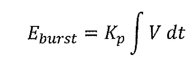
- the calibration module 904 determines the energy of the burst of the laser pulses from the average power. The energy produced during the defined period of time over which the power was measured is determined: Where E total is the energy of the laser beam 102 over the defined period of time, P measured is the power measurement taken by the power meter 202, T period is the defined period of time of the power meter 202 (e.g., one second). From E totai , the amount of energy within a burst is calculated using the burst rep rate:
- E burst is the energy of a burst
- E total is the energy of the unitary laser beam 102 over the defined period of time (e.g., one second)
- f burst is the burst rep rate
- K p is the calibration coefficient
- V is the voltage signal received from the PEM detector 208 such that the integral, / V dt, is the area under the curve of the voltage signal provided by the PEM detector 208 over the length of time of the burst
- E burst is the energy of a burst determined from the average power data received from the power meter 202.
- the calibration coefficient, K p has units of Watts per Volt.
- the SPEC module 906 is configured to calculate the energy of a single pulse using the calibration coefficient calculated by the calibration module 904.
- the SPEC module 906 receives voltage data from the PEM detector 208 that comprises a temporal profile of a single pulse in a unitary laser beam (e.g., single main pulse 502 or single pre-pulse 702).
- FIGURE 5 is a graph 500 output by the PEM detector 208 depicting a temporal profile of a single main pulse 502 in the unitary laser beam 102.
- the single main pulse 502 may be a pulse within the burst 402 or may be a pulse in a subsequent burst.
- the single main pulse 502 is captured by reducing the scope window 306 of the PEM detector 208.
- the main pulse 502 has an amplitude and a width (measured as length of time).
- the SPEC module 906 can integrate the main pulse 502.
- FIGURE 7 is a graph 700 output by a PEM detector depicting a temporal profile of a single pre-pulse 702 in the unitary laser beam 102.
- the single pre-pulse 702 is captured by reducing the length of time over which the PEM detector 208 measures the laser beam 102.
- the pre-pulse 702 has an amplitude and a width (measured as a length of time).
- the SPEC module 906 can integrate the pre-pulse 702. [36] Using the temporal profile of a single pulse, the energy of the single pulse is calculated according to the formula;
- E pulse is the energy of the pulse
- K p is the calibration coefficient for pulses of the wavelength of the pulse being measured
- V is the voltage signal received from the PEM detector 208 depicting a temporal profile of the pulse being measured such that the integral, J V dt, is the area under the curve of the voltage signal provided by the PEM detector 208 over the length of time of the pulse.
- the optional recalibration module 908 is configured to determine whether to recalibrate the PEM detector 208.
- the calibration coefficients may lose accuracy over time due to, for example, instrument drift, equipment deterioration, or degradation of the beam splitter from which the laser beam is received.
- the recalibration module 908 is configured to compare the power meter 202 measurement to a calculated power of the laser beam 102 using data provided by the PEM detector 208. As described herein, the comparison is made using a time period of one second.
- burst length 304 a burst period 304 a burst period 308, or several burst periods.
- the energy of the pulses over a burst is determined using the calibration coefficient:
- V is the voltage signal received from the PEM detector 208 such that the integral, J V dt, is the area under the curve of the voltage signal provided by the PEM detector 208 over the length of time of the burst and E burst is the calculated energy of a burst.
- the sum of laser pulse energy is used to determine the total energy of the laser beam 102 over the time period:
- E burst is the energy of a burst
- E total is the calculated energy of the laser beam 102 over the defined period of time (e.g., one second)
- ⁇ E burst is the sum of laser pulse energy over the defined period of time.
- the total energy is divided by the time period (e.g., one second):
- E total is the calculated energy of the laser beam 102 over the defined period of time
- P calcuiated is a power value calculated from the voltage signal received from the PEM detector 208
- T period is the defined period of time (e.g., one second).
- the recalibration module 908 can calculate a difference between the calculated power and the measured power. The difference may be expressed as percentage. To determine whether to recalibrate, the recalibration module 908 may compare the difference to a threshold. In some instances, if the two power values are more than 15% off, the recalibration module 908 instructs the calibration module 904 to recalculate the calibration coefficient. Based on the comparison, the recalibration manager 908 can instruct the calibration module 904 to update the calibration coefficient by recalculating the calibration coefficient during a subsequent burst of the pulses of the laser beam 102.
- the system 900 of FIGURE 9 is further configured to determine calibration coefficient used to determine the energy of a pre- pulse in a combined laser beam 102.
- the energy monitor 902 is located in the LPP EUV system 100 to measure a combined laser beam 102.
- the calibration module 904 uses a different set of calculations than those used when calibrating for a unitary laser beam. These calculations use the calibration coefficient calculated for the unitary laser beam 102 of the main pulses to determine a portion of the power measured by the power meter 202 attributable to the main pulses, then use the remaining portion of the power to determine the calibration coefficient for the pre-pulses in the combined laser beam.
- FIGURES 8 is an example temporal profile 800 of the voltage signal output by a PEM detector 208 of a combined pulse comprising a pre-pulse and a main pulse separated by a length of time.
- the combined laser beam 102 is generated by combining the unitary laser beams 102 into a single laser beam so that, within a burst of the combined laser beam 102, the pre-pulses of the burst 602 alternate with the main pulses of the burst 402.
- a pre-pulse 802 precedes a main pulse 804 by 15 microseconds.
- the laser pulses have a width (measured as a length of time) and an amplitude.
- the calibration module 904 and the SPEC module 906 can integrate the pre-pulse 802 separately from the main pulse 804.
- the integral is used to determine the calibration coefficient for calculating the energy of the pre-pulse and to calculate the energy of subsequent pre-pulses in a combined laser beam.
- the calibration module 904 calculates the power of the main pulses of the combined beam based on a portion of the voltage signal provided by the PEM detector 208 indicating the temporal profile of the main pulse within the combined pulse. Using the temporal profile, the energy of the main pulse is calculated according to the formula:
- E main pulse is the energy of the main pulse
- K mp is the calibration coefficient for the main pulses calculated for the unitary laser beam 102
- V is the voltage signal received from the PEM detector 208 depicting a temporal profile of the main pulse being measured such that the integral, dt, is the area under the curve of the voltage
- the average power of the combined pulse is measured by the power meter 202 over the defined period of time (e.g., one second). Based on the energy of the main pulse, the power attributable to the main pulses over the defined period of time is calculated as:
- E main pulse is the energy of the main pulse
- P main pulse is the calculated power of the main pulses
- T period is the defined period of time used by the power meter 202
- ⁇ E main pulses is the sum of the energy of the main pulses occurring over the defined period of time used by the power meter 202.
- P pre-pulse is the portion of the power measured by the power meter attributable to the pre-pulses of the combined pulse over the defined period of time
- P measured is the power of the combined pulse measured by the power meter 202
- P main pulse is the calculated power of the main pulses.
- the energy attributable to the pre-pulses is determined by:
- E pre-pulse is the total energy of the pre-pulse over the defined period of time used by the power meter 202
- P pre-pulse is the portion of the power measured by the power meter attributable to the pre-pulses of the combined pulse over the defined period of time
- T period is the defined period of time of the power meter 202 (e.g., one second).
- K pp is the calibration coefficient of the pre-pulses in the combined laser beam
- V is the voltage signal received from the PEM detector 208 such that the integral, / V dt, is the area under the curve of the voltage signal provided by the PEM detector 208 over at least a portion of the defined period of time
- E pre _ pulse is the total energy of the pre- pulse over the defined period of time used by the power meter 202.
- the calibration coefficient, K pp/ has units of Watts per Volt.
- the SPEC module 906 receives voltage data from the PEM detector 208 that comprises a temporal profile of a pair of a pre-pulse and a main pulse in a combined laser beam. The SPEC module 906 can then determine the energy of a subsequent pre-pulse using the formula:
- E pre-pulse is the energy of the single pre-pulse
- K pp is the calibration coefficient for pulses of the pre-pulse in the combined laser beam 102
- V is the voltage signal received from the PEM detector 208 depicting a temporal profile of the pre-pulse being measured such that the integral, / V dt, is the area under the curve of the voltage signal provided by the PEM detector 208 over the length of time of the pre-pulse.
- the optional recalibration module 908 can further determine whether to recalibrate the PEM detector 208 using the power meter 202 for the pre-pulses in the combined laser beam 102, as described above.
- the recalibration module 908 determines the power of the pulses by summing the energy of the pulses in the combined laser beam over a defined period of time corresponding to the power meter 202. The recalibration module 908 then compares a power calculated from the sum to the power measured by the power meter 202, as described above,
- FIGURE 10 is a flowchart of an example method 1000 of calculating the energy of a pulse, according to an example embodiment.
- the method 1000 may be performed by the system 900.
- a PEM detector is calibrated using a power meter for a beam of a first laser.
- the first laser can produce main pulses or pre-pulses in a unitary laser beam, as described above.
- FIGURE 11 is a flowchart of an example method 1100 of calibrating a PEM detector using a power meter to determine the energy of pulses within a unitary laser beam.
- the method 1100 may be performed as part of operation 1002 by, for example, the energy monitor 200 or 902 and the calibration module 904 of the system 900.
- a power measurement is received from the power meter (e.g., power meter 202).
- the power measurement indicates the average power of the pulses of the unitary laser beam 102 over a period of time.
- a voltage signal over a length of time is received from a PEM detector (e.g., PEM detector 208).
- the voltage signal is a temporal profile of a burst of the pulses of the unitary laser beam 102.
- the length of time over which data is collected by the PEM detector 208 is at least one burst within the period of time of the power meter 202.
- the calibration coefficient of the laser beam 102 is calculated.
- the calibration coefficient is calculated as described in connection with the calibration module 904.
- the calibration coefficient can be calculated by the calibration module 904.
- the method 1000 proceeds to an operation 1006, skipping operation 1004.
- the energy of a pulse is calculated.
- the energy of the pulse is calculated, for example, as described elsewhere herein in connection with the SPEC module 906.
- the SPEC module 906 performs the operation 1006.
- the method 1000 proceeds from the operation 1002 to the operation 1004.
- the PEM detector is calibrated for a combined beam to determine an energy of a pre- pulse within the combined beam.
- a second laser can produce pre-pulses in bursts, as described above, which are combined with main pulses in a combined laser beam 102.
- the calibration coefficient for the pre-pulses in the combined laser beam 102 is determined.
- the calibration coefficient for the pre-pulses in the combined laser beam 102 is determined separately from that of the pre-pulses in the unitary laser beam 102 because the optical components of the LPP EUV system 100 affect the relationship between the temporal profile of the pre-pulse and the power measured by the power meter 202 after the unitary laser beams 102 are combined.
- the calibration coefficient of the pre-pulses is determined based on a difference between the power measured by the power meter and the power attributable to the main pulses in the combined laser beam.
- FIGURE 12 is a flowchart of an example method 1200 of calibrating a PEM detector (e.g., PEM detector 208) using a power meter (e.g., power meter 202) on a combined laser beam having pre-pulses and main pulses.
- the method 1200 is an example method of performing the operation 1004 of the method 1000 when the laser beam measured by the energy monitor 200 is a combined laser beam.
- the method 1200 may be performed by, for example / the calibration module 904 of the system 900.
- the voltage data is received from the PEM detector 208 in the energy monitor 200 or 902.
- the voltage data is a temporal profile of the combined laser beam 102, as depicted in FIGURE 8.
- the length of time over which data is collected by the PEM detector 208 is at least a portion of the period of time of the power meter 202.
- the power attributable to the main pulses is determined.
- the power of the main pulses is determined as described in connection with the calibration module 904 and the SPEC module 906.
- the power data is received from the power meter 202.
- the power data indicates the average power of the pulses of the combined laser beam 102 over a period of time.
- the power attributable to the pre-pulses within the combined laser beam 102 is determined.
- the power of the pre-pulses is determined as described in connection with the calibration module 904 and the SPEC module 906.
- the calibration coefficient of the pre-pulses within the combined laser beam 102 is calculated.
- the calibration coefficient is calculated as described in connection with the calibration module 904.
- Proceeding to the operation 1006 when the laser beam measured by the energy monitor 200 is a combined laser beam the energy of the respective main pulses and the pre-pulses in the combined laser beam are calculated as described with respect to operation 1006, above.
- the calibration coefficient of the operation 1002 calculated for the unitary beam of main pulses is used to calculate the energy of a main pulse in the combined laser beam.
- the calibration coefficient of the operation 1004 is tised.
- the method 1000 can then proceed to optional operation 1008 as described above.
- the described method and apparatus can be implemented in numerous ways, including as a process, an apparatus, or a system.
- the methods described herein may be implemented by program instructions for instructing a processor to perform such methods, and such instructions recorded on a non-transitory computer readable storage medium such as a hard disk drive / floppy disk, optical disc such as a compact disc (CD) or digital versatile disc (DVD), flash memory, etc., or communicated over a computer network wherein the program instructions are sent over optical or electronic communication links.
- a non-transitory computer readable storage medium such as a hard disk drive / floppy disk, optical disc such as a compact disc (CD) or digital versatile disc (DVD), flash memory, etc.
Landscapes
- Physics & Mathematics (AREA)
- Engineering & Computer Science (AREA)
- Optics & Photonics (AREA)
- Plasma & Fusion (AREA)
- General Physics & Mathematics (AREA)
- Mechanical Engineering (AREA)
- Environmental & Geological Engineering (AREA)
- Epidemiology (AREA)
- Public Health (AREA)
- Health & Medical Sciences (AREA)
- X-Ray Techniques (AREA)
- Exposure And Positioning Against Photoresist Photosensitive Materials (AREA)
- Photometry And Measurement Of Optical Pulse Characteristics (AREA)
- Lasers (AREA)
- Optical Radar Systems And Details Thereof (AREA)
Abstract
Description




Claims
Priority Applications (3)
| Application Number | Priority Date | Filing Date | Title |
|---|---|---|---|
| KR1020167036388A KR102439233B1 (en) | 2014-07-14 | 2015-06-18 | Method of Calibration of Opto-Electromagnetic Sensors in Laser Sources |
| CN201580037841.2A CN106488826B (en) | 2014-07-14 | 2015-06-18 | Calibration of opto-electromagnetic sensors in laser sources |
| JP2016571417A JP6820747B2 (en) | 2014-07-14 | 2015-06-18 | Calibration of photoelectromagnetic sensor in laser light source |
Applications Claiming Priority (4)
| Application Number | Priority Date | Filing Date | Title |
|---|---|---|---|
| US14/330,526 US9239269B1 (en) | 2014-07-14 | 2014-07-14 | Calibration of photoelectromagnetic sensor in a laser source |
| US14/330,488 US9239268B1 (en) | 2014-07-14 | 2014-07-14 | Calibration of photoelectromagnetic sensor in a laser source |
| US14/330,488 | 2014-07-14 | ||
| US14/330,526 | 2014-07-14 |
Publications (1)
| Publication Number | Publication Date |
|---|---|
| WO2016010673A1 true WO2016010673A1 (en) | 2016-01-21 |
Family
ID=55078910
Family Applications (1)
| Application Number | Title | Priority Date | Filing Date |
|---|---|---|---|
| PCT/US2015/036489 Ceased WO2016010673A1 (en) | 2014-07-14 | 2015-06-18 | Calibration of photoelectromagnetic sensor in a laser source |
Country Status (5)
| Country | Link |
|---|---|
| JP (1) | JP6820747B2 (en) |
| KR (1) | KR102439233B1 (en) |
| CN (1) | CN106488826B (en) |
| TW (1) | TWI569688B (en) |
| WO (1) | WO2016010673A1 (en) |
Families Citing this family (3)
| Publication number | Priority date | Publication date | Assignee | Title |
|---|---|---|---|---|
| KR102084558B1 (en) * | 2017-09-22 | 2020-03-05 | 미쓰비시덴키 가부시키가이샤 | Laser processing equipment |
| CN111521264B (en) * | 2020-07-02 | 2020-09-22 | 北京瑞通科悦科技有限公司 | A fast calculation method and device for pulse energy measurement |
| CN113567903B (en) * | 2021-07-21 | 2023-04-28 | 清华大学 | Method, device, computer storage medium and terminal for realizing sensor calibration |
Citations (4)
| Publication number | Priority date | Publication date | Assignee | Title |
|---|---|---|---|---|
| US20040135517A1 (en) * | 2002-10-30 | 2004-07-15 | Xtreme Technologies Gmbh | Radiation source for generating extreme ultraviolet radiation |
| US20060192152A1 (en) * | 2005-02-28 | 2006-08-31 | Cymer, Inc. | LPP EUV light source drive laser system |
| US20070008517A1 (en) * | 2005-07-08 | 2007-01-11 | Cymer, Inc. | Systems and methods for EUV light source metrology |
| US20080017801A1 (en) * | 2004-03-10 | 2008-01-24 | Fomenkov Igor V | EUV light source |
Family Cites Families (16)
| Publication number | Priority date | Publication date | Assignee | Title |
|---|---|---|---|---|
| JP3542359B2 (en) * | 1992-12-24 | 2004-07-14 | キヤノン株式会社 | Pulse laser device and exposure apparatus using the same |
| JP2844288B2 (en) * | 1993-02-09 | 1999-01-06 | ミヤチテクノス株式会社 | Laser monitoring device |
| US6141081A (en) * | 1997-08-08 | 2000-10-31 | Cymer, Inc. | Stepper or scanner having two energy monitors for a laser |
| EP1502334B1 (en) * | 2002-05-07 | 2009-12-23 | Cymer, Inc. | High power deep ultraviolet laser with long life optics |
| DE10355866B3 (en) * | 2003-11-27 | 2005-04-14 | Jenoptik Laser, Optik, Systeme Gmbh | Optical device for extraction of measuring signal for laser power measurement uses optical surfaces on opposite sides of contamination-free hermetically sealed inner space for deflecting laser radiation onto sensor |
| US20060256679A1 (en) * | 2005-05-10 | 2006-11-16 | Kuang-Jung Chang | Laser power controlling method for recording data and related apparatus |
| US7615730B2 (en) * | 2007-11-30 | 2009-11-10 | Intel Corporation | Device and method for measuring wavelength of an optical signal |
| CN101429865A (en) * | 2008-12-05 | 2009-05-13 | 北京六合伟业科技有限公司 | Parameter-embedded analog transducer calibration method |
| JP5314433B2 (en) * | 2009-01-06 | 2013-10-16 | ギガフォトン株式会社 | Extreme ultraviolet light source device |
| CN102353446A (en) * | 2011-07-08 | 2012-02-15 | 西安炬光科技有限公司 | Method and system for testing power of pulsing laser |
| CN102394704B (en) * | 2011-07-15 | 2013-10-30 | 华中科技大学 | Device for automatically adjusting output power of array calibration signal source |
| JP6021454B2 (en) * | 2011-10-05 | 2016-11-09 | ギガフォトン株式会社 | Extreme ultraviolet light generation apparatus and extreme ultraviolet light generation method |
| CN102435829B (en) * | 2011-10-28 | 2013-08-14 | 哈尔滨工业大学 | Self-calibration method for optical voltage sensor |
| JP5818721B2 (en) * | 2012-03-06 | 2015-11-18 | 住友重機械工業株式会社 | Laser processing apparatus and laser processing method |
| JP6050607B2 (en) * | 2012-05-15 | 2016-12-21 | 株式会社アマダミヤチ | Laser processing apparatus and laser output calibration method |
| US8811440B2 (en) * | 2012-09-07 | 2014-08-19 | Asml Netherlands B.V. | System and method for seed laser mode stabilization |
-
2015
- 2015-06-17 TW TW104119556A patent/TWI569688B/en active
- 2015-06-18 WO PCT/US2015/036489 patent/WO2016010673A1/en not_active Ceased
- 2015-06-18 CN CN201580037841.2A patent/CN106488826B/en active Active
- 2015-06-18 KR KR1020167036388A patent/KR102439233B1/en active Active
- 2015-06-18 JP JP2016571417A patent/JP6820747B2/en active Active
Patent Citations (4)
| Publication number | Priority date | Publication date | Assignee | Title |
|---|---|---|---|---|
| US20040135517A1 (en) * | 2002-10-30 | 2004-07-15 | Xtreme Technologies Gmbh | Radiation source for generating extreme ultraviolet radiation |
| US20080017801A1 (en) * | 2004-03-10 | 2008-01-24 | Fomenkov Igor V | EUV light source |
| US20060192152A1 (en) * | 2005-02-28 | 2006-08-31 | Cymer, Inc. | LPP EUV light source drive laser system |
| US20070008517A1 (en) * | 2005-07-08 | 2007-01-11 | Cymer, Inc. | Systems and methods for EUV light source metrology |
Also Published As
| Publication number | Publication date |
|---|---|
| TWI569688B (en) | 2017-02-01 |
| TW201603649A (en) | 2016-01-16 |
| KR102439233B1 (en) | 2022-08-31 |
| CN106488826B (en) | 2019-08-23 |
| JP6820747B2 (en) | 2021-01-27 |
| KR20170031102A (en) | 2017-03-20 |
| CN106488826A (en) | 2017-03-08 |
| JP2017529553A (en) | 2017-10-05 |
Similar Documents
| Publication | Publication Date | Title |
|---|---|---|
| US9239268B1 (en) | Calibration of photoelectromagnetic sensor in a laser source | |
| JP7241143B2 (en) | Target expansion rate control in extreme ultraviolet light sources | |
| JP6195474B2 (en) | Extreme ultraviolet light generation apparatus and laser system control method in extreme ultraviolet light generation system | |
| US20130043401A1 (en) | Energy Sensors for Light Beam Alignment | |
| KR102367123B1 (en) | Controlling method in distance measuring device using TOF | |
| US9820368B2 (en) | Target expansion rate control in an extreme ultraviolet light source | |
| JP6866471B2 (en) | EUV light generator | |
| US9426872B1 (en) | System and method for controlling source laser firing in an LPP EUV light source | |
| JP2022176339A (en) | Optical pulse generation from extreme ultraviolet light source | |
| US9239269B1 (en) | Calibration of photoelectromagnetic sensor in a laser source | |
| KR102439233B1 (en) | Method of Calibration of Opto-Electromagnetic Sensors in Laser Sources | |
| KR101564391B1 (en) | System and method for compensating for thermal effects in an euv light source | |
| WO2018123035A1 (en) | Target photographing apparatus and extreme ultraviolet light generation apparatus | |
| US20160044772A1 (en) | System and method to reduce oscillations in extreme ultraviolet light generation | |
| NL2016111A (en) | Radiation Source. | |
| TWI642914B (en) | Methods of controlling an optical source in a photolithography system and a photolithography system | |
| KR102892676B1 (en) | Predictive correction scheduling device and method | |
| JPH09184900A (en) | Pulse X-ray irradiation device | |
| JP2023515743A (en) | control system for light source | |
| JP3941801B2 (en) | Method of irradiating pulsed X-rays | |
| JP2012099766A (en) | Exposure device and exposure amount control method therefor |
Legal Events
| Date | Code | Title | Description |
|---|---|---|---|
| 121 | Ep: the epo has been informed by wipo that ep was designated in this application |
Ref document number: 15821410 Country of ref document: EP Kind code of ref document: A1 |
|
| ENP | Entry into the national phase |
Ref document number: 2016571417 Country of ref document: JP Kind code of ref document: A |
|
| ENP | Entry into the national phase |
Ref document number: 20167036388 Country of ref document: KR Kind code of ref document: A |
|
| NENP | Non-entry into the national phase |
Ref country code: DE |
|
| 122 | Ep: pct application non-entry in european phase |
Ref document number: 15821410 Country of ref document: EP Kind code of ref document: A1 |