WO2016009952A1 - 車両用計器 - Google Patents
車両用計器 Download PDFInfo
- Publication number
- WO2016009952A1 WO2016009952A1 PCT/JP2015/069838 JP2015069838W WO2016009952A1 WO 2016009952 A1 WO2016009952 A1 WO 2016009952A1 JP 2015069838 W JP2015069838 W JP 2015069838W WO 2016009952 A1 WO2016009952 A1 WO 2016009952A1
- Authority
- WO
- WIPO (PCT)
- Prior art keywords
- horn
- battery
- terminal
- vehicle
- drive circuit
- Prior art date
- Legal status (The legal status is an assumption and is not a legal conclusion. Google has not performed a legal analysis and makes no representation as to the accuracy of the status listed.)
- Ceased
Links
Images

Classifications
-
- B—PERFORMING OPERATIONS; TRANSPORTING
- B60—VEHICLES IN GENERAL
- B60K—ARRANGEMENT OR MOUNTING OF PROPULSION UNITS OR OF TRANSMISSIONS IN VEHICLES; ARRANGEMENT OR MOUNTING OF PLURAL DIVERSE PRIME-MOVERS IN VEHICLES; AUXILIARY DRIVES FOR VEHICLES; INSTRUMENTATION OR DASHBOARDS FOR VEHICLES; ARRANGEMENTS IN CONNECTION WITH COOLING, AIR INTAKE, GAS EXHAUST OR FUEL SUPPLY OF PROPULSION UNITS IN VEHICLES
- B60K35/00—Instruments specially adapted for vehicles; Arrangement of instruments in or on vehicles
- B60K35/10—Input arrangements, i.e. from user to vehicle, associated with vehicle functions or specially adapted therefor
-
- B—PERFORMING OPERATIONS; TRANSPORTING
- B60—VEHICLES IN GENERAL
- B60K—ARRANGEMENT OR MOUNTING OF PROPULSION UNITS OR OF TRANSMISSIONS IN VEHICLES; ARRANGEMENT OR MOUNTING OF PLURAL DIVERSE PRIME-MOVERS IN VEHICLES; AUXILIARY DRIVES FOR VEHICLES; INSTRUMENTATION OR DASHBOARDS FOR VEHICLES; ARRANGEMENTS IN CONNECTION WITH COOLING, AIR INTAKE, GAS EXHAUST OR FUEL SUPPLY OF PROPULSION UNITS IN VEHICLES
- B60K35/00—Instruments specially adapted for vehicles; Arrangement of instruments in or on vehicles
- B60K35/20—Output arrangements, i.e. from vehicle to user, associated with vehicle functions or specially adapted therefor
- B60K35/21—Output arrangements, i.e. from vehicle to user, associated with vehicle functions or specially adapted therefor using visual output, e.g. blinking lights or matrix displays
- B60K35/22—Display screens
-
- B—PERFORMING OPERATIONS; TRANSPORTING
- B60—VEHICLES IN GENERAL
- B60K—ARRANGEMENT OR MOUNTING OF PROPULSION UNITS OR OF TRANSMISSIONS IN VEHICLES; ARRANGEMENT OR MOUNTING OF PLURAL DIVERSE PRIME-MOVERS IN VEHICLES; AUXILIARY DRIVES FOR VEHICLES; INSTRUMENTATION OR DASHBOARDS FOR VEHICLES; ARRANGEMENTS IN CONNECTION WITH COOLING, AIR INTAKE, GAS EXHAUST OR FUEL SUPPLY OF PROPULSION UNITS IN VEHICLES
- B60K35/00—Instruments specially adapted for vehicles; Arrangement of instruments in or on vehicles
- B60K35/80—Arrangements for controlling instruments
-
- B—PERFORMING OPERATIONS; TRANSPORTING
- B60—VEHICLES IN GENERAL
- B60R—VEHICLES, VEHICLE FITTINGS, OR VEHICLE PARTS, NOT OTHERWISE PROVIDED FOR
- B60R16/00—Electric or fluid circuits specially adapted for vehicles and not otherwise provided for; Arrangement of elements of electric or fluid circuits specially adapted for vehicles and not otherwise provided for
- B60R16/02—Electric or fluid circuits specially adapted for vehicles and not otherwise provided for; Arrangement of elements of electric or fluid circuits specially adapted for vehicles and not otherwise provided for electric constitutive elements
Definitions
- the present invention relates to a vehicular instrument, and more particularly to a vehicular instrument that can notify an abnormal condition when a battery is connected in reverse polarity.
- the battery positive and negative terminals (electrodes) and the in-vehicle electrical device may be connected in reverse.
- reverse connection is prevented by attaching an identification code to the plus and minus terminals, specializing the terminal shape, and managing the length of the cord short.
- Patent Document 1 Even if these countermeasures are taken, it is desired to generate an alarm and notify the reverse connection state when the reverse connection is erroneously made, and is disclosed in, for example, Patent Document 1.
- an object of the present invention is to pay attention to the above-described problem, and to provide a vehicle meter capable of alarming about a battery reverse connection state.
- the vehicle instrument of the present invention is in a vehicle instrument comprising a horn drive circuit for driving a horn provided between both electrodes of a battery, Control means for controlling the horn drive circuit based on an operation by a vehicle user;
- the horn drive circuit includes a field effect transistor, the first terminal is connected to the positive electrode side of the battery, the second terminal is connected to the negative electrode side of the battery, A third terminal for switching an energization state from the first terminal to the second terminal is connected to the control means.
- the horn driving circuit is configured such that when the negative electrode of the battery is connected to the first terminal side and the positive electrode of the battery is connected to the second terminal side, the second terminal to the first terminal It has a protective function of energizing the power.
- the circuit board on which the horn driving circuit is mounted and a case for housing the circuit board are provided, and the case has a waterproof structure.
- the present invention can warn about a battery reverse connection state by a circuit in a vehicle instrument.
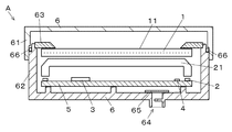
- FIG. 1 and 2 show a schematic configuration of a vehicle meter A according to an embodiment of the present invention
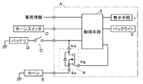
- FIG. 3 shows an electric circuit configuration of the vehicle meter A.
- the vehicle instrument A functions as a composite instrument, and includes a display board 1, a backlight 2, a control means 3, a circuit board 5 on which a horn drive circuit 4 is mounted, and these. It is comprised from the case 6 etc. to accommodate.
- the vehicle meter A is provided in the vicinity of the steering wheel in front of the vehicle so that the vehicle user can easily check during driving.
- the display unit 1 is a TFT-type transmissive liquid crystal panel that forms a desired image based on a control signal from the control unit 3, and the front of the driver's seat with the display surface 11 facing the driver side of the vehicle. Installed in the instrument panel.
- the display means 1 is a dot matrix type having a plurality of pixels arranged in a matrix, and realizes image display by driving each pixel.
- each pixel of the display means 1 is composed of sub-pixels of three colors provided with red (R), green (G), and blue (B) color filters, respectively. Display is possible.
- the display means 1 displays an instrument image as a pointer-type meter image composed of a plurality of pixels, and a display image such as a warning image and an indicator composed of a plurality of pixels.
- the instrument image is an image for instructing and displaying the state value of the vehicle travel information to the vehicle occupant.
- the speed indicator that indicates the vehicle speed value using the pointer image, and the fuel remaining by bar display. It includes a quantity meter, a background image indicating the background, a numerical image such as an accumulated mileage, and a mark image for displaying warnings and indicators, and a plurality of items can be displayed for each partitioned display area.
- the backlight 2 can be a light emitting diode that illuminates the display means 1 via the light guide 21.
- the backlight 2 is a chip component for surface mounting, and is mounted on a circuit board 5 provided on the back surface of the display means 1.
- the backlight 2 is electrically connected to the control means 3, and emits illumination light by being driven based on a control signal given from the control means 3.
- the control means 3 can be controlled to emit and output from the backlight 2 at a desired luminance by pulse width modulation control.
- the light guide 21 is formed of a light-transmitting synthetic resin such as acrylic in a flat plate shape, and is arranged in parallel with the display unit 1 on the back side of the display unit 1.
- the light guide 21 reflects and diffuses the incident light from the adjacent backlight 2 and emits the light from the exit surface on the display means 1 side, so that the emission luminance on the exit surface is spread over the entire area. Make it almost uniform.
- the backlight 2 illuminates and transmits the entire display unit 1 from behind by the light from the emission surface.
- the display unit 1, the backlight 2 and the light guide 21 constitute a display unit that can be illuminated and displayed so that the user can visually recognize it even in a dark environment such as at night.
- the display means 1 which consists of a liquid crystal panel, and the illumination means which consists of the backlight 2 was shown, it can replace with self-luminous type panels, such as an organic electroluminescent panel.
- the control means 3 includes a CPU and a memory, and is composed of a known microcomputer that controls the backlight 2 and the display means 1 by transmitting a control signal by calculating a predetermined program. It is mounted on the substrate 5.
- the control means 3 is connected to the display means 1, the backlight 2, and the horn drive circuit 4, respectively, and is electrically connected (communication connection) so that vehicle speed and the like can be input as vehicle information.
- the vehicle information includes vehicle travel information including the gear position and direction instruction operation, the state of the vehicle, and an abnormal signal from each device.
- the control means 3 includes a drawing processing circuit, and the drawing processing circuit performs drawing arithmetic processing such as generating an image to be displayed on the display means 1 using image data stored in a storage unit in advance.
- the storage unit for storing image data is preferably a nonvolatile memory such as a flash memory.
- the drawing processing circuit can display a display image 12 on the display surface 11 by outputting a control signal for driving each constituent pixel of the display unit 1.
- a drive IC using a FET field effect transistor
- the wiring between both electrodes of the battery B is connected in series with the horn E, and the drain (first terminal) 4d side is connected to the horn drive circuit 4 It is connected to the vehicle battery B via the start switch D, and the source (second terminal) 4s side is connected to the battery B via the vehicle horn E and the vehicle body frame (ground connection).
- the horn drive circuit 4 is connected to the control means 3 on the gate 4g side, and from the drain 4d to the source 4s based on a control signal issued from the control means 3 according to the on / off state of the horn switch C.
- the horn switch C is provided on the handle and is switched to an on / off state and output to the control means 3 of the vehicular instrument A as an operation signal by a pressing pressure operation of the vehicle user.
- the horn drive circuit 4 is connected to the gate current by the control means 3 in addition to the energization by the parasitic diode of the FET. Regardless of, has a function of allowing energization from the source 4s to the drain 4d.
- the battery B is reversely connected, in addition to the path where the FET generates heat via the parasitic diode of the FET, a path through which a larger current can flow than the parasitic diode can be secured, and the heat generation of the FET itself can be reduced.
- the horn E can be continuously sounded. The horn E can be applied for a horn having no polarity.
- the horn E sounds regardless of whether the vehicle meter A is in operation immediately or when the start switch D is turned on. I can recognize that. Further, by assigning the alarm function to the horn drive circuit 4 when the horn E is driven at normal time, it is advantageous in that an increase in electronic components can be suppressed and a new waterproof structure is not required.
- circuit board 5 a printed wiring board on which various electronic components such as the display means 1, the backlight 2, the control means 3, the horn driving circuit 4, and the connector are mounted can be applied. It is stored in the case 6.
- the case 6 is formed by fitting a plurality of molded products made of synthetic resin to form a space for housing components such as the circuit board 5 and the display means 1, and the light transmitting portion 61 facing the display surface 11 of the display means 1. And a light shielding portion 62 for holding each component at a predetermined position.
- the case 6 is provided with a turn-back portion 63 that divides the display area of the display unit 1 and covers an unnecessary part other than the display area of the display unit 1.
- the light transmitting portion 61 of the case 6 may be a transparent synthetic resin material such as acrylic, or a member with adjusted transmittance.
- a vent hole 64 is provided on the circuit board 5 side of the case 6 so that heat generated from electronic components such as the backlight 2 can be exhausted.
- the case 6 is waterproof (not shown) so that water does not pass through a hole through which a cable for electrical connection with the outside of the vehicle meter A is used or a waterproof packing 66 is used to fit the cases 6 together.
- a waterproof structure is provided so that rainwater or the like does not easily enter the inside of the vehicle meter A, such as a cover.
- Such a vehicle meter A is a vehicle meter A including a horn drive circuit 4 that drives a horn E provided between both electrodes of a battery B, and controls the horn drive circuit 4 based on an operation by a vehicle user.
- the horn drive circuit 4 is provided with an FET, the drain 4d is connected to the positive electrode side of the battery B, the source 4s is connected to the negative electrode side of the battery B via the horn E, and the source is connected from the drain 4d.
- a gate 4g for switching the energization state to 4s is connected to the control means 3.
- the horn drive circuit 4 in the vehicle meter A can cause the horn E to output an alarm about the reverse connection state of the battery B.
- the horn driving circuit 4 has a protection function for energizing the drain 4d from the source 4s when the negative electrode of the battery B is connected to the drain 4d side and the positive electrode of the battery B is connected to the source 4s side via the horn E. Accordingly, the horn E can be driven stably even when the battery B is reversely connected. In particular, it is effective for a vehicle instrument A having a waterproof structure and high airtightness, and a vehicle instrument A for a motorcycle that is used in direct sunlight and easily becomes high temperature.
- the circuit board 5 which mounts the horn drive circuit 4 and the case 6 which accommodates this circuit board 5 are provided, and the case 6 is used in an environment exposed to rain water such as a motorcycle by having a waterproof structure. Even in the case of a vehicle, a warning drive circuit can be mounted using this waterproof structure.
- the vehicular instrument A connected to the battery B via the start switch D has been described as an example, but it can be assumed that the horn drive circuit 4 is connected to the battery B without the start switch D. In this case, when the battery B is reversely connected, the horn E is immediately activated.
- a drive IC such as a high-side driver or a low-side driver can be selectively applied, and the connection position of the battery B or the horn E, By appropriately selecting source / drain wirings and the like, it is possible to realize a configuration that operates in the same manner as in the above-described embodiment.
- the present invention relates to a vehicle instrument that is mounted on a moving body and displays various types of information, and is suitable, for example, as an instrument mounted on a moving body equipped with an automobile, a motorcycle, an agricultural machine, or a construction machine.
Landscapes
- Engineering & Computer Science (AREA)
- Mechanical Engineering (AREA)
- Chemical & Material Sciences (AREA)
- Combustion & Propulsion (AREA)
- Transportation (AREA)
- Instrument Panels (AREA)
Abstract
バッテリ逆接続状態について警報できる車両用計器を提供する。 バッテリBの両電極間に設けられるホーンEを駆動するホーン駆動回路4を備える車両用計器Aにおいて、車両利用者による操作に基づいてホーン駆動回路4を制御する制御手段3を備え、ホーン駆動回路4は、FETを設け、ドレイン4dをバッテリBのプラス電極側に接続し、ソース4sをホーンEを介してバッテリBのマイナス電極側に接続し、ドレイン4dからソース4sへの通電状態を切り替えるためのゲート4gを制御手段3に接続する。
Description
本発明は、車両用計器に関し、特にバッテリの逆極性接続の際に、異常状態を報知できる車両用計器に関する。
車両のメンテナンス時等に車載電気装置とバッテリとの接続状態を解除して再接続する際に、バッテリのプラスおよびマイナス端子(電極)と車載電気装置とを誤って逆に接続してしまうことを避けるために、プラスおよびマイナス端子に識別符号を付したり、端子形状を特殊化したり、コードの長さを短く管理するなどして、逆接続を防止するようにしている。
また、これら対策を施しても、なお誤って逆接続したときに警報を発生して逆接続状態を報知することが望まれており、例えば、特許文献1に開示されている。
しかしながら、バッテリが逆接続状態を報知するための警報構造は、専用に設ける必要があるため、電子部品など増加してしまう課題があった。
また、特に、自動車のエンジンルーム内やオートバイなど雨水に晒される車両に適用する場合にあっては、これら電子部品の増加にともなって、車載するスペースの確保や、防水などの対策を施す必要があるなど課題があった。
そこで本発明の目的は、上述した課題に着目してなされたものであって、バッテリ逆接続状態について警報できる車両用計器を提供することにある。
本発明の車両用計器は、
バッテリの両電極間に設けられるホーンを駆動するホーン駆動回路を備える車両用計器において、
車両利用者による操作に基づいて前記ホーン駆動回路を制御する制御手段を備え、
前記ホーン駆動回路は、電界効果トランジスタを設け、第1の端子をバッテリのプラス電極側に接続し、第2の端子を前記バッテリのマイナス電極側に接続し、
前記第1の端子から第2の端子への通電状態を切り替えるための第3の端子を前記制御手段に接続することを特徴とする。
バッテリの両電極間に設けられるホーンを駆動するホーン駆動回路を備える車両用計器において、
車両利用者による操作に基づいて前記ホーン駆動回路を制御する制御手段を備え、
前記ホーン駆動回路は、電界効果トランジスタを設け、第1の端子をバッテリのプラス電極側に接続し、第2の端子を前記バッテリのマイナス電極側に接続し、
前記第1の端子から第2の端子への通電状態を切り替えるための第3の端子を前記制御手段に接続することを特徴とする。
また、前記ホーン駆動回路は、前記第1の端子側に前記バッテリのマイナス電極、前記第2の端子側に前記バッテリのプラス電極が接続された場合に、前記第2の端子から第1の端子へ通電する保護機能を有することを特徴とする。
また、前記ホーン駆動回路を実装する回路基板と、前記回路基板を収納するケースとを備え、前記ケースは、防水構造を有することを特徴とする。
本発明は、車両用計器内の回路によって、バッテリ逆接続状態について警報できる。
以下、本発明の車両用表示装置の実施の形態として、オートバイ用の車両用計器に適用したものを例に挙げて図面を用いて説明する。
図1、2は、本発明の実施形態による車両用計器Aの概略構成を示し、図3は、車両用計器Aの電気回路構成を示している。
図1~3に示すように、車両用計器Aは、複合計器として機能するものであり、表示手段1、バックライト2、制御手段3、ホーン駆動回路4を実装する回路基板5と、これらを収納するケース6等から構成されている。車両用計器Aは、車両利用者が運転中に確認しやすいように車両前方のハンドル付近に設けられる。
表示手段1は、制御手段3からの制御信号に基づいて所望の画像を形成するTFT型の透過液晶パネルであり、表示面11が車両の運転者側に対向するようにして当該運転席の前方のインストルメントパネルに設置される。この表示手段1は、マトリクス状に配された複数の画素を有するドットマトリクス型であり、それら各画素が駆動されることによって画像表示を実現する。ここで表示手段1の各画素は、赤色(R)、緑色(G)、青色(B)のカラーフィルタがそれぞれ設けられた三色のサブ画素から構成されており、表示面11において画像のフルカラー表示が可能となっている。
この場合、表示手段1は、図1に示すように、複数の画素からなり指針式のメーター画像としての計器画像や、複数の画素からなり警告画像やインジケータなどの表示画像を表示する。なお、計器画像は、車両の走行情報の状態値を車両の乗員へ計測値を指示表示するための画像であり、この場合、指針画像を用いて車速値を示す速度計、バー表示による燃料残量計、並びに背景を示す背景画像や積算走行距離などの数値画像、警告やインジケータ表示を行うマーク画像を含んでおり、区画された表示エリア毎に複数項目表示できる。
バックライト2は、導光体21を介して表示手段1を照明する発光ダイオードを適用できる。バックライト2は表面実装用のチップ部品であり、表示手段1の背面に設けられる回路基板5に実装されている。バックライト2は、制御手段3と電気接続されており、制御手段3から与えられる制御信号に基づいて駆動されることで照明光を放射出力する。この場合、制御手段3は、パルス幅変調制御によって、バックライト2から所望の輝度にて照射出力されるように制御できる。
導光体21は、アクリルなど光透過性の合成樹脂で平板状に形成されており、表示手段1の背面側に表示手段1と平行に配置されている。また、導光体21は、隣接して位置するバックライト2からの入射光を反射、拡散して表示手段1側の出射面から出射することにより、出射面における発光輝度をその全域に亘って略均一にする。以上によりバックライト2は、出射面からの光により、表示手段1の全体を後方から透過照明する。
これら表示手段1、バックライト2、導光体21によって、夜間等暗い環境であっても利用者が視認可能なように照明して表示できる表示ユニットが構成される。なお、液晶パネルからなる表示手段1とバックライト2からなる照明手段とによって該表示ユニットを構成するものを示したが、有機ELパネルなどの自発光型のパネルに代替することもできる。
制御手段3は、CPU及びメモリを有し、所定プログラムを演算することによって、バックライト2や表示手段1などに制御信号を送信して制御する周知のマイクロコンピュータからなり、車両用計器Aの回路基板5に実装されている。制御手段3は、表示手段1、バックライト2、ホーン駆動回路4、にそれぞれ接続し、また、車速などを車両情報として入力可能に電気接続(通信接続)がなされている。ここで車両情報は、ギアポジションや方向指示操作などを含む車両の走行情報や車両の状態、各機器からの異常信号を含んでいる。
なお、車両用計器A外との通信や、電源の取り込みなどは、回路基板5に設けられる図示しないコネクタを介してケーブル接続されるが、ケース6の図示しない孔を通じて他の電子ユニットやバッテリB、ホーンスイッチCなどに接続される。
制御手段3は、描画処理回路を含んでおり、描画処理回路は、予め格納された記憶部の画像データを用いて表示手段1に表示させる画像を生成するなど描画演算処理を行う。なお、画像データを格納する記憶部は、フラッシュメモリなどの不揮発性メモリが好適である。描画処理回路は、例えば、表示手段1の各構成画素を駆動するための制御信号を出力して表示画像12を表示面11に表示できる。
ホーン駆動回路4は、FET(電界効果トランジスタ)を用いた駆動ICを適用でき、この場合、バッテリBの両電極間の配線においてホーンEと直列に接続され、ドレイン(第1の端子)4d側が起動スイッチDを介して車載のバッテリBに接続され、ソース(第2の端子)4s側が車載のホーンE、車体フレームを介してバッテリBに接続される(グランド接続)。また、ホーン駆動回路4は、ゲート4g側が、制御手段3に接続されており、ホーンスイッチCのオン/オフ状態に応じて制御手段3から発せられる制御信号に基づいて、ドレイン4dからソース4sへの通電を許可してホーンEに警笛動作(鳴動)させることができる。なお、ホーンスイッチCは、ハンドルに設けられ、車両利用者の押し圧操作によって、オン/オフ状態を切り替えて操作信号として車両用計器Aの制御手段3へ出力する。
なお、仮に、バッテリBのプラス電極と、マイナス電極(グランド)とが逆に接続されてしまった場合、ホーン駆動回路4は、FETの寄生ダイオードによる通電の他に、制御手段3によるゲート電流とは関係なくソース4sからドレイン4dへの通電を許可させる機能を有している。これによってバッテリBの逆接続時、FETの寄生ダイオードを経由してFETが発熱してしまう経路の他に、寄生ダイオードよりも大きな電流を流せる経路を確保し、FET自体の発熱を低減できるため、ホーン駆動回路4の熱破損を防止しながら、継続的にホーンEを鳴動させることができる。なお、ホーンEは、極性を持たない警笛用のものを適用できる。
従って、車両利用者は、バッテリBを逆接続した場合には、直ちに、または起動スイッチDをオンした際に、車両用計器Aの稼働有無に関わらずホーンEが鳴動するため、異常状態であることを認識できる。また、この警報機能について、ホーンEを通常時に駆動する際のホーン駆動回路4に割り当てることで、電子部品の増加を抑止できる他、新たな防水構造も必要ない点で有利である。
回路基板5は、表示手段1や、バックライト2、制御手段3、ホーン駆動回路4や、前記コネクタなど各種電子部品を実装するプリント配線基板を適用できる。ケース6内に収納される。
ケース6は、合成樹脂からなる複数の成形品を嵌め合わせて、回路基板5や表示手段1等の部品を収納する空間を形成するもので、表示手段1の表示面11を臨む光透過部61と、各部品を所定位置に保持する遮光部62とからなる。
また、ケース6は、表示手段1の表示領域を区画するとともに、表示手段1の表示領域以外の不要な部分を覆い隠す見返し部63を設けている。なお、ケース6の光透過部61は、アクリルなどの透明な合成樹脂材であってもよいし、透過率が調整された部材を用いることもできる。
また、ケース6の回路基板5側には、通気穴64が設けられ、バックライト2などの電子部品からの発熱を排熱できる。この場合、計器Aが外部環境に晒されるため、雨や埃などが計器A内に侵入することを防ぐ必要があり、通気穴64を覆う多孔質膜65を貼り付けている。また、ケース6は、ケース6同士を気密に嵌め合わせるために、防水パッキン66を用いたり、車両用計器A外と電気接続するためのケーブルを通す孔から水が通らないように、図示しない防水カバーが設けられるなど、車両用計器A内部に雨水等が侵入しにくいように防水構造を有する。
斯かる車両用計器Aは、バッテリBの両電極間に設けられるホーンEを駆動するホーン駆動回路4を備える車両用計器Aにおいて、車両利用者による操作に基づいてホーン駆動回路4を制御する制御手段3を備え、ホーン駆動回路4は、FETを設け、ドレイン4dをバッテリBのプラス電極側に接続し、ソース4sをホーンEを介してバッテリBのマイナス電極側に接続し、ドレイン4dからソース4sへの通電状態を切り替えるためのゲート4gを制御手段3に接続する。
従って、車両用計器A内のホーン駆動回路4によって、バッテリBの逆接続状態についてホーンEに警報出力させることができる。
また、ホーン駆動回路4は、ドレイン4d側にバッテリBのマイナス電極、ソース4s側にホーンEを介してバッテリBのプラス電極が接続された場合に、ソース4sからドレイン4dへ通電する保護機能を有することによって、FETの発熱を抑えて通電できるため、バッテリBが逆接続時であっても安定してホーンEを駆動できる。特に、防水構造を有し気密性の高い車両用計器Aや、直射日光下で使用され高温になりやすいオートバイ用の車両用計器Aに有効である。
また、ホーン駆動回路4を実装する回路基板5と、この回路基板5を収納するケース6とを備え、ケース6は、防水構造を有することによって、オートバイなど雨水に晒される環境下で使用される車両であっても、この防水構造を兼用して警報用の駆動回路を搭載できる。
なお、本発明の車両用計器を上述した実施の形態の構成にて例に挙げて説明したが、本発明はこれに限定されるものではなく、他の構成においても、本発明の要旨を逸脱しない範囲において種々の改良、並びに設計の変更が可能なことは勿論である。
例えば、起動スイッチDを介してバッテリBと接続する車両用計器Aについて例にあげて説明したが、ホーン駆動回路4が、起動スイッチDを介さずにバッテリBに接続する場合も想定でき、この場合、バッテリBに逆接続した際、直ちにホーンEを鳴動させる構成になる。
また、ホーン駆動回路4としてFETを用いるものについて例にあげて説明したが、ハイサイドドライバ、またはローサイドドライバなどの駆動ICを選択的に適用することもでき、バッテリBやホーンEの接続位置、ソース/ドレインの配線など適宜に選択することによって、上述実施の形態と同様に作用する構成を実現できる。
本発明は、移動体に搭載して各種情報を表示する車両用計器に関して、例えば、自動車やオートバイ、あるいは農業機械や建設機械を備えた移動体に搭載される計器として好適である。
1 表示手段
11 表示面
12 表示画像
2 バックライト
21 導光体
3 制御手段
4 ホーン駆動回路
5 回路基板
6 ケース
A 車両用計器
B バッテリ
C ホーンスイッチ
D 起動スイッチ
E ホーン
11 表示面
12 表示画像
2 バックライト
21 導光体
3 制御手段
4 ホーン駆動回路
5 回路基板
6 ケース
A 車両用計器
B バッテリ
C ホーンスイッチ
D 起動スイッチ
E ホーン
Claims (3)
- バッテリの両電極間に設けられるホーンを駆動するホーン駆動回路を備える車両用計器において、
車両利用者による操作に基づいて前記ホーン駆動回路を制御する制御手段を備え、
前記ホーン駆動回路は、電界効果トランジスタを設け、第1の端子をバッテリのプラス電極側に接続し、第2の端子を前記バッテリのマイナス電極側に接続し、
前記第1の端子から第2の端子への通電状態を切り替えるための第3の端子を前記制御手段に接続することを特徴とする車両用計器。 - 前記ホーン駆動回路は、前記第1の端子側に前記バッテリのマイナス電極、前記第2の端子側に前記バッテリのプラス電極が接続された場合に、前記第2の端子から第1の端子へ通電する保護機能を有することを特徴とする請求項1に記載の車両用計器。
- 前記ホーン駆動回路を実装する回路基板と、この回路基板を収納するケースとを備え、
前記ケースは、防水構造を有することを特徴とする請求項1または請求項2に記載の車両用計器。
Applications Claiming Priority (2)
| Application Number | Priority Date | Filing Date | Title |
|---|---|---|---|
| JP2014-144562 | 2014-07-14 | ||
| JP2014144562A JP2016020157A (ja) | 2014-07-14 | 2014-07-14 | 車両用計器 |
Publications (1)
| Publication Number | Publication Date |
|---|---|
| WO2016009952A1 true WO2016009952A1 (ja) | 2016-01-21 |
Family
ID=55078446
Family Applications (1)
| Application Number | Title | Priority Date | Filing Date |
|---|---|---|---|
| PCT/JP2015/069838 Ceased WO2016009952A1 (ja) | 2014-07-14 | 2015-07-10 | 車両用計器 |
Country Status (2)
| Country | Link |
|---|---|
| JP (1) | JP2016020157A (ja) |
| WO (1) | WO2016009952A1 (ja) |
Families Citing this family (2)
| Publication number | Priority date | Publication date | Assignee | Title |
|---|---|---|---|---|
| CN108450054B (zh) | 2016-02-04 | 2021-06-01 | 株式会社美姿把 | 电动机驱动装置及电动机驱动方法 |
| JP2019217972A (ja) * | 2018-06-21 | 2019-12-26 | 株式会社デンソー | 車両用表示装置 |
Citations (2)
| Publication number | Priority date | Publication date | Assignee | Title |
|---|---|---|---|---|
| JPH09308095A (ja) * | 1996-05-09 | 1997-11-28 | Yazaki Corp | 車載バッテリの逆接続警告装置 |
| JP2011239557A (ja) * | 2010-05-10 | 2011-11-24 | Sumitomo Wiring Syst Ltd | 電気接続箱 |
-
2014
- 2014-07-14 JP JP2014144562A patent/JP2016020157A/ja active Pending
-
2015
- 2015-07-10 WO PCT/JP2015/069838 patent/WO2016009952A1/ja not_active Ceased
Patent Citations (2)
| Publication number | Priority date | Publication date | Assignee | Title |
|---|---|---|---|---|
| JPH09308095A (ja) * | 1996-05-09 | 1997-11-28 | Yazaki Corp | 車載バッテリの逆接続警告装置 |
| JP2011239557A (ja) * | 2010-05-10 | 2011-11-24 | Sumitomo Wiring Syst Ltd | 電気接続箱 |
Also Published As
| Publication number | Publication date |
|---|---|
| JP2016020157A (ja) | 2016-02-04 |
Similar Documents
| Publication | Publication Date | Title |
|---|---|---|
| JP4626710B2 (ja) | 車両用表示装置 | |
| WO2015002258A1 (ja) | 車両用表示装置 | |
| JP6314718B2 (ja) | 車両用計器 | |
| JP5780412B2 (ja) | 車両用表示装置 | |
| JP2019192432A (ja) | 車両用照明装置、車両用灯具、車両用灯具付きウィンドウパネル、車載ディスプレイ | |
| WO1998026254A1 (fr) | Compteur pour vehicule | |
| JP2016020157A (ja) | 車両用計器 | |
| JP5982848B2 (ja) | 車両用表示装置 | |
| JP2015049994A (ja) | 光反射型表示装置および車両用灯具 | |
| JP2010237373A (ja) | フルカラー表示装置 | |
| JP2009151251A (ja) | 表示装置 | |
| JP2014235790A (ja) | 有機el表示装置 | |
| JP4055394B2 (ja) | 車両用表示装置 | |
| JP5817298B2 (ja) | 車両用表示装置の防水構造 | |
| JP5013178B2 (ja) | 車両用表示装置 | |
| US8480253B1 (en) | Vehicle exterior lighting systems and methods | |
| JP2010076462A (ja) | 車両用表示装置 | |
| JP5125923B2 (ja) | 車両用表示装置 | |
| JP7722057B2 (ja) | 車両用計器 | |
| JP5733021B2 (ja) | 車両用表示装置 | |
| JP2008158174A (ja) | 表示装置 | |
| JP2024077122A (ja) | 液晶表示ユニットの駆動回路 | |
| JP2006267557A (ja) | 表示パネル、表示装置、および移動体の表示モジュール | |
| JP7008263B2 (ja) | 車両用計器 | |
| JP2020062946A (ja) | 車両用計器 |
Legal Events
| Date | Code | Title | Description |
|---|---|---|---|
| 121 | Ep: the epo has been informed by wipo that ep was designated in this application |
Ref document number: 15822495 Country of ref document: EP Kind code of ref document: A1 |
|
| NENP | Non-entry into the national phase |
Ref country code: DE |
|
| 122 | Ep: pct application non-entry in european phase |
Ref document number: 15822495 Country of ref document: EP Kind code of ref document: A1 |