WO2016009874A1 - 車両用シートリクライニング装置 - Google Patents
車両用シートリクライニング装置 Download PDFInfo
- Publication number
- WO2016009874A1 WO2016009874A1 PCT/JP2015/069430 JP2015069430W WO2016009874A1 WO 2016009874 A1 WO2016009874 A1 WO 2016009874A1 JP 2015069430 W JP2015069430 W JP 2015069430W WO 2016009874 A1 WO2016009874 A1 WO 2016009874A1
- Authority
- WO
- WIPO (PCT)
- Prior art keywords
- memory member
- memory
- rotating
- guide hole
- reclining device
- Prior art date
- Legal status (The legal status is an assumption and is not a legal conclusion. Google has not performed a legal analysis and makes no representation as to the accuracy of the status listed.)
- Ceased
Links
Images








Classifications
-
- B—PERFORMING OPERATIONS; TRANSPORTING
- B60—VEHICLES IN GENERAL
- B60N—SEATS SPECIALLY ADAPTED FOR VEHICLES; VEHICLE PASSENGER ACCOMMODATION NOT OTHERWISE PROVIDED FOR
- B60N2/00—Seats specially adapted for vehicles; Arrangement or mounting of seats in vehicles
- B60N2/02—Seats specially adapted for vehicles; Arrangement or mounting of seats in vehicles the seat or part thereof being movable, e.g. adjustable
- B60N2/22—Seats specially adapted for vehicles; Arrangement or mounting of seats in vehicles the seat or part thereof being movable, e.g. adjustable the back-rest being adjustable
- B60N2/235—Seats specially adapted for vehicles; Arrangement or mounting of seats in vehicles the seat or part thereof being movable, e.g. adjustable the back-rest being adjustable by gear-pawl type mechanisms
- B60N2/2352—Seats specially adapted for vehicles; Arrangement or mounting of seats in vehicles the seat or part thereof being movable, e.g. adjustable the back-rest being adjustable by gear-pawl type mechanisms with external pawls
- B60N2/2354—Seats specially adapted for vehicles; Arrangement or mounting of seats in vehicles the seat or part thereof being movable, e.g. adjustable the back-rest being adjustable by gear-pawl type mechanisms with external pawls and provided with memory locks
-
- B—PERFORMING OPERATIONS; TRANSPORTING
- B60—VEHICLES IN GENERAL
- B60N—SEATS SPECIALLY ADAPTED FOR VEHICLES; VEHICLE PASSENGER ACCOMMODATION NOT OTHERWISE PROVIDED FOR
- B60N2/00—Seats specially adapted for vehicles; Arrangement or mounting of seats in vehicles
- B60N2/02—Seats specially adapted for vehicles; Arrangement or mounting of seats in vehicles the seat or part thereof being movable, e.g. adjustable
- B60N2/22—Seats specially adapted for vehicles; Arrangement or mounting of seats in vehicles the seat or part thereof being movable, e.g. adjustable the back-rest being adjustable
- B60N2/235—Seats specially adapted for vehicles; Arrangement or mounting of seats in vehicles the seat or part thereof being movable, e.g. adjustable the back-rest being adjustable by gear-pawl type mechanisms
- B60N2/2356—Seats specially adapted for vehicles; Arrangement or mounting of seats in vehicles the seat or part thereof being movable, e.g. adjustable the back-rest being adjustable by gear-pawl type mechanisms with internal pawls
- B60N2/2358—Seats specially adapted for vehicles; Arrangement or mounting of seats in vehicles the seat or part thereof being movable, e.g. adjustable the back-rest being adjustable by gear-pawl type mechanisms with internal pawls and provided with memory locks
-
- B—PERFORMING OPERATIONS; TRANSPORTING
- B60—VEHICLES IN GENERAL
- B60N—SEATS SPECIALLY ADAPTED FOR VEHICLES; VEHICLE PASSENGER ACCOMMODATION NOT OTHERWISE PROVIDED FOR
- B60N2/00—Seats specially adapted for vehicles; Arrangement or mounting of seats in vehicles
- B60N2/02—Seats specially adapted for vehicles; Arrangement or mounting of seats in vehicles the seat or part thereof being movable, e.g. adjustable
- B60N2/20—Seats specially adapted for vehicles; Arrangement or mounting of seats in vehicles the seat or part thereof being movable, e.g. adjustable the back-rest being tiltable, e.g. to permit easy access
-
- B—PERFORMING OPERATIONS; TRANSPORTING
- B60—VEHICLES IN GENERAL
- B60N—SEATS SPECIALLY ADAPTED FOR VEHICLES; VEHICLE PASSENGER ACCOMMODATION NOT OTHERWISE PROVIDED FOR
- B60N2/00—Seats specially adapted for vehicles; Arrangement or mounting of seats in vehicles
- B60N2/02—Seats specially adapted for vehicles; Arrangement or mounting of seats in vehicles the seat or part thereof being movable, e.g. adjustable
- B60N2/22—Seats specially adapted for vehicles; Arrangement or mounting of seats in vehicles the seat or part thereof being movable, e.g. adjustable the back-rest being adjustable
- B60N2/2227—Seats specially adapted for vehicles; Arrangement or mounting of seats in vehicles the seat or part thereof being movable, e.g. adjustable the back-rest being adjustable and provided with braking systems
-
- B—PERFORMING OPERATIONS; TRANSPORTING
- B60—VEHICLES IN GENERAL
- B60N—SEATS SPECIALLY ADAPTED FOR VEHICLES; VEHICLE PASSENGER ACCOMMODATION NOT OTHERWISE PROVIDED FOR
- B60N2/00—Seats specially adapted for vehicles; Arrangement or mounting of seats in vehicles
- B60N2/02—Seats specially adapted for vehicles; Arrangement or mounting of seats in vehicles the seat or part thereof being movable, e.g. adjustable
- B60N2/22—Seats specially adapted for vehicles; Arrangement or mounting of seats in vehicles the seat or part thereof being movable, e.g. adjustable the back-rest being adjustable
- B60N2/235—Seats specially adapted for vehicles; Arrangement or mounting of seats in vehicles the seat or part thereof being movable, e.g. adjustable the back-rest being adjustable by gear-pawl type mechanisms
- B60N2/2356—Seats specially adapted for vehicles; Arrangement or mounting of seats in vehicles the seat or part thereof being movable, e.g. adjustable the back-rest being adjustable by gear-pawl type mechanisms with internal pawls
- B60N2/236—Seats specially adapted for vehicles; Arrangement or mounting of seats in vehicles the seat or part thereof being movable, e.g. adjustable the back-rest being adjustable by gear-pawl type mechanisms with internal pawls linearly movable
Definitions
- the present invention relates to a vehicle seat reclining device.
- a first rotating member Conventionally, a first rotating member, a second rotating member arranged coaxially with the first rotating member, and a lock member for restricting relative rotation between the first and second rotating members
- a seat reclining device for vehicles equipped with.
- the seat reclining device described in Patent Literature 1 further includes a first memory member and a second memory member.
- the first memory member is engaged with the outer surface of the first rotating member by friction.
- the second memory member regulates the rotation of the first memory member relative to the second rotation member by engaging the first memory member at a predetermined relative rotation position set in advance.
- the lock member is locked and unlocked in conjunction with the engagement / disengagement operation of the second memory member with respect to the first memory member during the walk-in operation for improving the ease of getting on and off the rear seat by moving the seat back forward.
- the lock is activated.
- the seat back that has been operated forward can be returned to the tilted position before the forward operation.
- the locking member unlocks in conjunction with the detaching operation of the second memory member with respect to the first memory member. That is, when the second memory member is detached from the first memory member, the first memory member and the first rotating member are integrally rotated based on the frictional engagement force.
- the second memory member is engaged with the first memory member at a predetermined relative rotational position, so that the seatback returns to the tilted position before the forward operation.
- this seat reclining device includes a plate-like member having a long hole-like guide hole through which the memory pin is inserted. The memory pin is engaged with and disengaged from the first memory member by being supported in the guide hole while being movable in the longitudinal direction of the guide hole.
- An object of the present invention is to provide a vehicle seat reclining device capable of engaging and disengaging a memory member more accurately.
- a vehicle seat reclining device includes a first rotating member, a second rotating member arranged coaxially with the first rotating member, A lock member that restricts relative rotation between the first and second rotating members, and a frictional engagement with the outer surface of the first rotating member, so that the first rotating member and the first rotating member rotate coaxially.
- a first memory member movable and relatively rotatable against a frictional engagement force; a second memory member detachable with respect to the first memory member; and the second memory member as the first memory member.
- an operation mechanism for locking and unlocking the lock member in conjunction with the engagement / disengagement operation is provided.
- the first memory member is slidably contacted with the second memory member to restrict the engaging operation of the second memory member accompanied by the locking operation of the locking member, and the first memory member is When the second memory member is in a predetermined relative rotation position with respect to the second rotation member, the second memory member is allowed to engage with the second memory member inserted by the engagement operation.
- the operation mechanism includes a long hole-shaped guide hole provided in the plate-like member.
- the second memory member has a shaft portion inserted through the guide hole.
- the second memory member is configured to engage and disengage with respect to the first memory member by being supported in a state where the shaft portion is movable along the longitudinal direction of the guide hole.
- a support wall protruding in the thickness direction of the plate-like member is provided at the peripheral edge of the guide hole.
- a vehicle seat reclining device includes a first rotating member, a second rotating member arranged coaxially with the first rotating member, and the first and second components.
- a lock member that restricts relative rotation between the rotating members of the first rotating member, and a frictional engagement force that can rotate integrally with the first rotating member by frictional engagement with the outer surface of the first rotating member.
- a first memory member that can rotate relative to the first memory member; a second memory member that can be engaged with and disengaged from the first memory member; And an operation mechanism for locking and unlocking the lock member in conjunction with the engagement / disengagement operation.
- the first memory member is slidably contacted with the second memory member to restrict the engaging operation of the second memory member accompanied by the locking operation of the locking member, and the first memory member is When the second memory member is in a predetermined relative rotation position with respect to the second rotation member, the second memory member is allowed to engage with the second memory member inserted by the engagement operation.
- the operation mechanism includes a long hole-shaped guide hole provided in the plate-like member.
- the second memory member has a shaft portion inserted through the guide hole.
- the second memory member is configured to engage and disengage with respect to the first memory member by being supported in a state where the shaft portion is movable along the longitudinal direction of the guide hole.
- the guide holes are defined by a pair of inner wall surfaces that are located on both sides in the short direction of the guide holes and extend in the longitudinal direction.
- the shaft portion of the second memory member is inserted into the guide hole while being in sliding contact with the pair of inner wall surfaces of the guide hole and in surface contact with at least one of the inner wall surfaces.
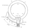
- Sectional drawing along the VI-VI line of FIG. Sectional drawing along the VII-VII line of FIG. FIG. 8 is a cross-sectional view taken along line VIII-VIII in FIG. 6.
- Operation movement explanatory drawing of a seat reclining apparatus (1st relative rotation position: Desorption state). Operation explanatory drawing of a seat reclining device (at the time of forward operation). Operation
- operation explanatory drawing of a seat reclining apparatus at the time of walk-in operation
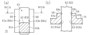
- (A) is a side view of the guide hole through which the shaft portion of the second memory member is inserted, and (b) is a cross-sectional view of the guide hole through which the shaft portion of the second memory member is inserted (XVIIb-XVIIb cross section).
- (A) is a side view of another example guide hole through which the shaft portion of the second memory member is inserted, and (b) is a cross-sectional view of another guide hole through which the shaft portion of the second memory member is inserted ( XVIIIb-XVIIIb cross section).
- (A) is a side view of another example guide hole through which the shaft portion of the second memory member is inserted
- (b) is a cross-sectional view of another guide hole through which the shaft portion of the second memory member is inserted ( XIXb-XIXb cross section).
- the vehicle seat 1 includes a seat cushion 2 and a seat back 3 provided so as to be tiltable with respect to the rear end of the seat cushion 2.
- the vehicle floor 4 is provided with a pair of left and right lower rails 5 and upper rails 6 that move on the lower rails 5 along the longitudinal direction of the lower rails 5.
- the seat 1 is configured to be capable of position adjustment in the vehicle front-rear direction by being supported on both upper rails 6.
- the seat 1 is further provided with a seat reclining device 10 that can adjust the tilt angle of the seat back 3.
- a recliner 11 is interposed between the seat cushion 2 and the seat back 3.
- the recliner 11 restricts the rotation of the seat back 3 relative to the seat cushion 2 and allows the rotation.
- the vehicle occupant can adjust the tilt angle of the seat back 3 by the recliner 11 by operating the operation handle 13 disposed on the side of the seat cushion 2.
- a support plate 15 as a plate-like member extends upward from the rear end of the side frame 14 that forms the skeleton of the seat cushion 2.
- the seat back side member 16 that forms the skeleton of the seat back 3 is disposed on the inner side (back side) of each support plate 15 provided on the side of the seat cushion 2 (before the direction orthogonal to the paper surface of FIG. 2). ing.
- the recliner 11 is sandwiched between an upper end of a support plate 15 disposed to face the width direction of the seat 1 and a base end of the seat back side member 16. The recliner 11 is provided on both sides of the seat back 3 in the width direction.
- the recliner 11 has first and second rotating members (an upper bracket and a second rotating member) having a rotation axis L which is a common rotation center and arranged in a relatively rotatable manner.
- Lower brackets 21 and 22 are provided.
- Both the first and second rotating members 21 and 22 have a substantially disk-shaped outer shape.
- annular peripheral wall portions 23 and 24 are formed, respectively.
- the peripheral wall portion 23 protrudes from the main body portion 21 a of the first rotating member 21 toward the main body portion 22 a of the second rotating member 22.
- the peripheral wall portion 24 protrudes from the main body portion 22 a of the second rotating member 22 toward the main body portion 21 a of the first rotating member 21.
- the first and second rotating members 21 and 22 are arranged at a coaxial position in a state in which the first and second rotating members 21 and 22 can be relatively rotated by fitting the peripheral wall portions 23 and 24 to each other.
- the first and second rotating members 21 are arranged in a stepped manner with respect to the peripheral wall portion 24 of the second rotating member 22 located at the outermost peripheral portions of the first and second rotating members 21 and 22.
- Second peripheral wall portions 23a and 23b are provided.
- the outer diameter of the first peripheral wall portion 23a located on the radially outer side is substantially equal to the inner diameter of the peripheral wall portion 24 of the second rotating member 22.
- the recliner 11 includes an annular holder 25.
- the annular holder 25 has a cross-sectional shape that allows the first peripheral wall portion 23a of the first rotating member 21 and the peripheral wall portion 24 of the second rotating member 22 to be sandwiched in the thickness direction (left-right direction in FIG. 6). ing.
- the annular holder 25 is fitted on the outer periphery of the first and second rotating members 21 and 22, thereby allowing relative rotation between the first and second rotating members 21 and 22 and rotating. The relative movement along the movement axis L is restricted.
- the first rotating member 21 is fixed to the base end of the seat back side member 16, and the second rotating member 22 is fixed to the upper end of the support plate 15 of the seat cushion 2. Yes. Between the first and second rotating members 21 and 22, there are three lock members (poles) that restrict relative rotation between the first and second rotating members 21 and 22 by engaging with each other. ) 30 is interposed.
- the second rotating member 22 has a guide portion 31 that holds each lock member 30 as an engaging member movably in the radial direction inside the peripheral wall portion 24 in the radial direction.
- Each lock member 30 is formed in a plate shape.
- three holding protrusions 32 are provided on the opposing surface 22s (the left surface in FIG. 6) of the second rotating member 22 that faces the first rotating member 21 in the axial direction of the rotating shaft L. Is formed.
- the holding protrusions 32 are arranged at substantially equal intervals in the circumferential direction.
- Each holding protrusion 32 is formed in a substantially sector shape. Thereby, all the side wall parts 32a of the holding
- Each lock member 30 is disposed between adjacent holding projections 32.
- each holding protrusion 32 functions as the guide part 31 by sandwiching the lock member 30 between the side walls 32 a of the holding protrusions 32 adjacent in the circumferential direction.
- each lock member 30 is hold
- Each lock member 30 is held by the second rotating member 22 in a state where relative movement in the circumferential direction is restricted by contact with each side wall 32a.
- the first peripheral wall portion 23 a of the peripheral wall portion 23 of the first rotating member 21 has inner teeth 33 that protrude radially inward over the entire inner circumference that forms an annular shape. Is formed. Furthermore, external teeth 34 that can mesh with the internal teeth 33 of the first peripheral wall portion 23a are formed at the distal ends of the lock members 30 facing the radially outer side while being held by the second rotating member 22. Yes. The outer teeth 34 of each lock member 30 mesh with the inner teeth 33 of the first rotation member 21, whereby the second rotation member 22 that holds each lock member 30 and the first rotation member 21. Relative rotation is restricted.
- the seat reclining device 10 includes an operation shaft 40 to which the operation handle 13 is fixed.
- the operation shaft 40 rotates integrally with the operation handle 13.
- the operating shaft 40 passes through the recliner 11 in the thickness direction.
- the operation shaft 40 passes through the central portions of the main body portions 21 a and 22 a of the first and second rotating members 21 and 22.
- the recliner 11 includes a cam member 35 that is fixed so as not to rotate relative to the operation shaft 40.
- the operation shaft 40 has a pair of plane portions that are formed in a width of two surfaces and are parallel to each other.
- the cam member 35 has a fitting hole 35a having a two-sided width shape.
- the cam member 35 is arranged on the inner side in the radial direction of each lock member 30 in a state where the peripheral portion is in contact with the base end of each lock member 30.
- each lock member 30 moves in the radial direction based on the rotation of the cam member 35, so that the external teeth 34 of each lock member 30 are engaged with and disengaged from the internal teeth 33 of the first rotation member 21. It is configured.
- the cam member 35 rotates each lock member 30 in the radial direction by rotating in the clockwise direction of FIGS. 7 and 8 with respect to the second rotation member 22 holding each lock member 30 as described above. Move outward. Thereby, the recliner 11 cannot relatively rotate the first and second rotating members 21 and 22 because the outer teeth 34 of the lock members 30 mesh with the inner teeth 33 of the first rotating member 21. To the locked state in which the tilt angle of the seat back 3 with respect to the seat cushion 2 is fixed.
- the cam member 35 moves each lock member 30 radially inward by rotating in the counterclockwise direction of FIGS. 7 and 8.
- the recliner 11 causes the relative rotation between the first and second rotating members 21 and 22 by the outer teeth 34 of the lock members 30 being detached from the inner teeth 33 of the first rotating member 21.
- the movement is allowed and the seat back 3 is switched to an unlocked state in which the tilt angle of the seat back 3 can be adjusted.
- the operating shaft 40 that is the rotating shaft of the cam member 35 is biased in the locking direction, which is the clockwise direction in FIGS. 7 and 8, by the elastic force of a torsion coil spring (not shown). Further, the operation shaft 40 is in the counterclockwise direction of FIGS. 7 and 8 by pulling up the operation handle 13 disposed on the side of the seat cushion 2 (rotating operation in the clockwise direction of FIG. 2). It rotates in the unlocking direction. When the lifting operation of the operation handle 13 is stopped, the operation shaft 40 rotates in the locking direction based on the elastic force of the torsion coil spring.
- control protrusions 41 are provided on the inner periphery of the second peripheral wall portion 23 b of the first rotating member 21.
- Each control protrusion 41 is arranged in the circumferential direction at equal angular intervals.
- Each lock member 30 is provided with an engaging protrusion 42 that protrudes radially outward toward the inner periphery of the second peripheral wall 23b.
- the recliner 11 controls the locking and unlocking operations of the lock members 30 when the control protrusions 41 and the engagement protrusions 42 come into contact with each other.
- the recliner 11 is configured such that the engaging protrusions 42 move radially inward from the control protrusions 41 of the second peripheral wall 23b when the lock members 30 are unlocked. Thereby, in the unlocked state, the engagement protrusions 42 of the respective lock members 30 and the respective control protrusions 41 of the second peripheral wall 23b do not interfere with each other, and the first and second rotating members 21, 22 is relatively rotatable.
- the seat reclining device 10 is configured so that the function of the recliner 11 is within the range of the tilt angle ⁇ 1 tilted forward with respect to the preset basic position P0 and the tilt angle ⁇ 2 tilted backward.
- the tilt angle of the back 3 can be changed and fixed.
- the seat 1 can tilt the seat back 3 forward by the tilt angle ⁇ 3 with reference to the basic position P0, exceeding the upright position P1, which is the adjustment limit of the tilt angle on the front side (maximum forward tilt position P3). ).
- a maximum forward tilt position P3 (tilt angle ⁇ 3) and a maximum rearward tilt position P2 (tilt angle ⁇ 2) of the seat back 3 are defined by a stopper (not shown).
- the unlocking state of the recliner 11 is maintained and the tilt angle of the seat back 3 is not fixed even if the operation handle 13 is not continuously lifted.
- the seat reclining device 10 is a walk-in lever capable of rotating the operation shaft 40 in the unlocking direction (clockwise direction in FIG. 2) independently of the operation handle 13. 50.
- the seat 1 is provided with a biasing member 45 such as a spiral spring that biases the seat back 3 forward.
- the seat reclining device 10 unlocks the recliner 11 provided between the seat back 3 and the seat cushion 2 regardless of the lifting operation of the operation handle 13, and places the seat back 3 in the maximum forward tilt position. It has a walk-in function that can be tilted to P3.
- the walk-in lever 50 has an insertion hole 51 through which the operation shaft 40 is inserted.
- a wire cable 52 is connected to the tip of the walk-in lever 50.
- the walk-in lever 50 rotates in the unlocking direction (the clockwise direction in FIGS. 2 and 9) about the operation shaft 40 inserted through the insertion hole 51.
- the insertion hole 51 has an inner diameter R2 that is substantially equal to or slightly larger than the diameter R1 of the operation shaft 40 having a two-sided width shape (dimension in the longitudinal direction of a substantially rectangular cross section). is doing.
- a pair of engagement protrusions 51 a and 51 b are provided on the inner periphery of the insertion hole 51. Only when the walk-in lever 50 rotates in the unlocking direction, the pair of engaging protrusions 51 a and 51 b engage with the operation shaft 40 to rotate the operation shaft 40 integrally with the walk-in lever 50. .
- a walk-in handle 53 that can be operated from the rear of the seat 1 is provided at the upper end of the seat back 3.
- the other end of the wire cable 52 is connected to the walk-in handle 53.
- the operation input to the walk-in handle 53 is transmitted to the walk-in lever 50 via the wire cable 52, so that the walk-in lever is integrated with the operation shaft 40 inserted into the insertion hole 51.
- 50 is configured to rotate in the unlocking direction.
- the engagement protrusions 51 a and 51 b provided on the inner periphery of the insertion hole 51 do not engage with the two-surface width shape of the operation shaft 40. .
- the seat reclining device 10 allows the operation shaft 40 inserted into the insertion hole 51 to rotate in the unlocking direction without the rotation of the walk-in lever 50 during the normal reclining operation by lifting the operation handle 13. It is configured to move.
- the seat reclining device 10 includes a first memory member 61 that frictionally engages the outer surface of the first rotating member 21 constituting the recliner 11, and a first memory member 61. And a second memory member 62 detachably provided with respect to the first memory member 61.
- the first memory member 61 is fitted to the peripheral wall portion 23 of the first rotating member 21.
- the first memory member 61 can be integrally rotated coaxially with the first rotating member 21 based on the frictional engagement force with the peripheral wall portion 23, and resists the frictional engagement force with the peripheral wall portion 23 in the first rotation.
- the movable member 21 can be rotated.
- the first and second rotating members 21 and 22 are formed by plastic processing (pressing) a plate-like metal material. For this reason, the main-body parts 21a and 22a and the surrounding wall parts 23 and 24 are integrally formed.
- the step pushed out from the inner surface S1 of the first rotating member 21 to the outer surface S2 (from the right side to the left side in FIG. 6) by plastic deformation.
- a portion is formed as the outer periphery of the second peripheral wall portion 23b.
- a step portion pushed toward the outer surface S2 by plastic deformation is formed as the third peripheral wall portion 23c.
- the first memory member 61 is fitted to the outer peripheral surface of the third peripheral wall portion 23 c of the first rotating member 21.
- the second memory member 62 has a substantially square-shaped outer shape.
- the support plate 15 to which the second rotating member 22 is fixed is provided with a guide hole 63 through which the second memory member 62 is inserted.
- the guide hole 63 has a long hole shape extending in the radial direction of the recliner 11, that is, in the vertical direction of FIGS. 2 and 6.
- the second memory member 62 is supported so as to be movable in the guide hole 63.
- the first memory member 61 is formed with an engaging groove 65 in which the second memory member 62 moving in the guide hole 63 can be engaged and disengaged.
- the guide hole 63 is formed by fitting a cylindrical member 67 into a through hole 66 provided in the support plate 15.
- the cylindrical member 67 has an axial length D1 that is larger than the thickness D0 of the support plate 15 that is a plate-like member.
- the peripheral wall 67 a of the cylindrical member 67 functions as a support wall 68 that protrudes in the thickness direction of the support plate 15 at the periphery of the guide hole 63.
- the seat reclining device 10 includes a link member 64 that connects the second memory member 62 and the walk-in lever 50.
- the link member 64 has the second memory member in the guide hole 63 when the walk-in lever 50 rotates in the unlocking direction (the clockwise direction in FIGS. 11 and 12).
- 62 is configured to move in the radial direction of the recliner 11, that is, in a direction away from the first memory member 61 (lower side in FIGS. 11 and 12).
- the operation mechanism 70 for engaging and disengaging the second memory member 62 with respect to the first memory member 61 and locking and unlocking each lock member 30 in conjunction with the engagement and disengagement operation of the second memory member 62 is provided. It is formed.
- the first memory member 61 includes a frictional engagement portion 71 having an annular shape (C-ring shape) in which a part in the circumferential direction is broken.
- a plurality of sliding contact projections 72 are formed on the inner periphery of the friction engagement portion 71.
- the first memory member 61 slides each sliding contact protrusion 72 to the first rotating member 21 and fits the friction engaging portion 71 to the peripheral wall portion 23 (23c) of the first rotating member 21. By doing so, an appropriate frictional engagement force is generated between the first rotating member 21 and the first rotating member 21.
- the first memory member 61 includes an arc-shaped extending portion 73 having a circumferential end portion 73a in the vicinity of the fracture portion 71x.
- the arc-shaped extending portion 73 protrudes radially outward from the friction engagement portion 71.
- the first memory member 61 further includes a protruding portion 74 that protrudes radially outward from the friction engagement portion 71.
- a fracture portion 71 x is provided between the protruding portion 74, the first memory member 61, and the circumferential end portion 73 a of the arc-shaped extending portion 73.
- the engaging groove 65 of the first memory member 61 includes the side surface 74a of the projecting portion 74 and the circumferential end portion 73a of the arc-like extending portion 73 as a pair of side wall surfaces 65s arranged to face each other in the circumferential direction. .
- the fracture portion 71x is provided between the first end 71a and the second end 71b of the friction engagement portion 71, and the engagement groove 65 is formed on the side wall surface 65s near the first end 71a and the side near the second end 71b. Wall surface 65s.
- the second memory member 62 when the walk-in handle 53 is not operated, the second memory member 62 is radially inward of the first memory member 61 in the guide hole 63 of the support plate 15 (see FIG. 11). 11) and is inserted into the engagement groove 65 of the first memory member 61. Thereby, the second memory member 62 is engaged with the first memory member 61, and the rotation of the first memory member 61 with respect to the second rotating member 22 fixed to the support plate 15 is restricted.
- each lock member 30 is unlocked (detached) with the rotation of the walk-in lever 50 of the operation mechanism 70, so the first and second rotating members 21, Relative rotation between 22 is allowed. Accordingly, the first rotation member 21 and the first memory member 61 can be integrally rotated based on the frictional engagement force.
- a sliding contact surface 75 is formed on the outer peripheral portion of the arc-shaped extending portion 73 of the first memory member 61.
- the seat back 3 is tilted forward because the recliner 11 between the seat back 3 and the seat cushion 2 is unlocked while being biased by the biasing member 45 (see FIG. 6).
- the first memory member 61 rotates integrally with the first rotation member 21, so that the second memory member 62 comes into sliding contact with the sliding contact surface 75 of the first memory member 61.
- the engagement operation of the second memory member 62 toward the radially inner side of the first memory member 61 is restricted. Therefore, the rotation of the walk-in lever 50 in the counterclockwise direction of FIGS. 13 and 14, and The locking operation of each locking member 30 is restricted. Thereby, since the unlocked state of the recliner 11 is maintained, the seat back 3 is urged by the urging member 45 and reaches the maximum forward tilt position P3.
- the unlocked state of the recliner 11 is maintained as long as the second memory member 62 is in sliding contact with the sliding contact surface 75 of the first memory member 61.
- the second memory member 62 rotates integrally with the first rotating member 21 and the first memory member 61 based on the frictional engagement force. It moves in the circumferential direction on the sliding contact surface 75 to a position where it can be inserted into the engaging groove 65.
- a memory function is realized that allows the seat back 3 to be moved forward and returned to the tilted position before the operation.
- the distal end of the protruding portion 74 of the first memory member 61 is more radial than the sliding contact surface 75 of the arc-shaped extending portion 73 that forms both side wall surfaces 65 s of the engaging groove 65 together with the protruding portion 74. Projects outward.
- the protrusion 74 is integrated with the first rotating member 21 when the seat back 3 tilts backward while the relative rotation of the first and second rotating members 21 and 22 is involved.
- the second memory member 62 abuts on the second rotating member 22 in the vicinity of the support plate 15.
- the protrusion 74 abuts on the second memory member 62 at the first relative rotation position Q1 where the second memory member 62 can be inserted into the engagement groove 65.
- the protruding portion 74 functions as the stopper portion 76, so that the integral rotation of the first rotating member 21 and the first memory member 61 based on the frictional engagement force is restricted.
- the arc-shaped extending portion 73 of the first memory member 61 has a second projecting portion 77 in the vicinity of the circumferential end 73 b on the opposite side to the engaging groove 65.
- the tip of the second protrusion 77 protrudes radially outward from the slidable contact surface 75 of the arcuate extension 73, as with the protrusion 74.
- the first back so that the seat back 3 can reach the maximum forward tilt position P3 based on the urging force of the urging member 45 even after the second memory member 62 contacts the second projecting portion 77 constituting the stopper portion 78.
- the frictional engagement force of the first memory member 61 with respect to the peripheral wall portion 23 of the rotating member 21 is set.
- the relative rotation angle ⁇ between the first relative rotation position Q ⁇ b> 1 and the second relative rotation position Q ⁇ b> 2 set in the first memory member 61 is set in the seat back 3. It is set equal to the tilt angle ⁇ 3 from the basic position P0 to the maximum forward tilt position P3.
- the seat back 3 when the tilt position Px of the seat back 3 before the forward operation is between the basic position P0 and the upright position P1, the seat back 3 reaches the maximum forward tilt position P3 by the forward operation.
- the tilt angle ⁇ 4 until the tilt is smaller than the tilt angle ⁇ 3 from the basic position P0 to the maximum forward tilt position P3 ( ⁇ 4 ⁇ 3).
- the tilt angle ⁇ 4 is smaller than the relative rotation angle ⁇ between the first relative rotation position Q1 and the second relative rotation position Q2 set in the first memory member 61.
- the second memory member 62 does not reach the end of the sliding contact surface 75 that contacts the second projecting portion 77, so that the first rotating member 21 is frictionally contacted.
- the relative rotation position of the engaging first memory member 61 is maintained.
- the seatback 3 that has been operated forward is caused to move rearward, so that the seatback 3 returns to the tilt position Px before the forward operation.
- the tilt position Px ′ of the seat back 3 before the forward tilt operation is behind the basic position P0, the tilt until the seat back 3 reaches the maximum forward tilt position P3 by the forward tilt operation.
- the angle ⁇ 5 is larger than the tilt angle ⁇ 3 from the basic position P0 to the maximum forward tilt position P3 ( ⁇ 5> ⁇ 3).
- the tilt angle ⁇ 5 is larger than the relative rotation angle ⁇ between the first relative rotation position Q1 and the second relative rotation position Q2 set in the first memory member 61.
- the second memory member 62 comes into contact with the second projecting portion 77, and the second projecting portion 77 functions as the stopper portion 78.
- the integral rotation of the first rotation member 21 and the first memory member 61 is restricted.
- the seat back 3 reaches the maximum forward tilt position P3 based on the biasing force of the biasing member 45. 1
- the relative rotation position with respect to the memory member 61 is corrected.
- the relative rotation angle of the first memory member 61 with respect to the second rotation member 22 is set between the first relative rotation position Q1 and the second relative rotation position Q2. matches ⁇ .
- the seat back 3 is returned to the basic position P ⁇ b> 0 by causing the seat back 3 that has been moved forward to be moved backward.
- the second memory member 62 of the present embodiment is provided with a shaft portion 83 having a substantially square cross section.
- the shaft portion 83 is inserted into a guide hole 63 provided in the support plate 15 and is supported in a movable state along the longitudinal direction of the guide hole. Thereby, the second memory member 62 can be engaged and disengaged with respect to the first memory member 61.
- the shaft width W1 (length of one side in the square cross section) of the shaft portion 83 is set to a value substantially equal to the groove width W0 (length in the short direction) of the guide hole 63 formed in the shape of the long hole. .
- the two surfaces 83 a and 83 b of the shaft portion 83 positioned in the groove width direction are in sliding contact with both inner wall surfaces 63 a and 63 b that define the guide hole 63.
- Both inner wall surfaces 63 a and 63 b are located on both sides in the short direction of the guide hole 63 and extend in the longitudinal direction of the guide hole 63.
- the two surfaces 83a and 83b of the shaft portion 83 are in surface contact with the inner wall surfaces 63a and 63b and the inner wall surface 68s of the support wall 68 that is continuous with the inner wall surfaces 63a and 63b. Then, the seat reclining device 10 of the present embodiment thereby suppresses the tilt of the second memory member 62 that moves in the longitudinal direction of the guide hole 63.
- the seat reclining device 10 includes a first rotating member 21, a second rotating member 22 disposed coaxially with the first rotating member 21, and the first and second rotating members 21. , 22 is provided with a lock member 30 for restricting relative rotation between the two members.
- the seat reclining device 10 includes a first memory member 61 and a second memory member 62 that can be engaged with and disengaged from the first memory member 61.
- the first memory member 61 can be integrally rotated coaxially with the first rotating member 21 by friction engagement with the outer surface S2 of the first rotating member 21, and resists frictional engagement force.
- the first rotation member 21 can be rotated.
- the seat reclining device 10 includes an operation mechanism 70 capable of engaging / disengaging the second memory member 62 and locking / unlocking the lock member 30 in conjunction with the engagement / disengagement operation.
- the first memory member 61 is provided with a sliding contact surface 75.
- the slidable contact surface 75 slidably contacts the second memory member 62, thereby restricting the engaging operation of the second memory member 62 accompanied with the locking operation of the locking member 30.
- the first memory member 61 is provided with an engagement groove 65. When the first memory member 61 is at a predetermined relative rotation position (first relative rotation position Q1) with respect to the second rotation member 22, the engagement operation of the second memory member 62 with respect to the engagement groove 65 is performed. Allowed, whereby the second memory member 62 is inserted and engaged in the engagement groove 65. That is, the seat reclining device 10 is configured to be capable of restricting relative rotation of the first memory member 61 with respect to the second rotation member 22.
- the first rotation is performed against the frictional engagement force of the first memory member 61.
- the member 21 can be rotated with respect to the second rotating member 22.
- the tilt angle of the seat back 3 can be adjusted by a normal reclining operation that does not involve the engagement / disengagement of the second memory member 62 with respect to the first memory member 61.
- the first memory member 61 is in a state of being able to rotate integrally with the first rotating member 21 based on the frictional engagement force. That is, when the first and second rotating members 21 and 22 rotate relative to each other, the sliding contact surface 75 of the first memory member 61 comes into sliding contact with the second memory member 62, and the locking operation of the locking member 30 is accompanied. The engaging operation of the second memory member 62 is restricted. As a result, an unlocked state in which the tilt angle of the seat back 3 is not fixed is maintained. Thereby, the seat back 3 can be tilted to the maximum tilt position without continuing the unlocking operation via the operation mechanism 70.
- the first memory member 61 that rotates integrally with the first rotation member 21 returns to the first relative rotation position Q ⁇ b> 1 with respect to the second rotation member 22.
- the second memory member 62 can be inserted into the engaging groove 65. Accordingly, since the engaging operation of the second memory member 62 accompanied with the locking operation of the locking member 30 is allowed, the tilt angle of the seat back 3 can be fixed at the tilt position Px before the tilt operation.
- the above configuration has a better assembling property than the configuration of the recliner built-in type in which each memory member is disposed between the first and second rotating members 21 and 22.
- the apparatus can be thinned and high-precision locking and unlocking operations can be performed by utilizing the high degree of freedom of spatial arrangement.
- the slidable contact surface 75 is formed by the first memory member 61 based on the frictional engagement force when the seat back 3 tilts forward while the first and second rotating members 21 and 22 are relatively rotated. It is formed at a position in sliding contact with the second memory member 62 by integrally rotating with the one rotating member 21.
- the unlocking operation via the operation mechanism 70 is maintained by restricting the engaging operation of the second memory member 62 accompanied by the locking operation of the locking member 30 and maintaining the unlocked state.
- the seat back 3 can be tilted to the maximum forward tilt position P3.
- the first memory member 61 includes a protrusion 74.
- the protrusion 74 can insert the second memory member 62 into the engaging groove 65. It contacts the second memory member 62 at the 1 relative rotation position Q1. Since the protruding portion 74 functions as the stopper portion 76, the integral rotation of the first rotation member 21 and the first memory member 61 based on the frictional engagement force can be restricted.
- the first memory member 61 reaches the first relative rotation position Q1 in which the second memory member 62 can be inserted into the engagement groove 65. Based on the frictional engagement force between the first memory member 61 and the first rotating member 21, it is possible to give the seat back 3 a sense of resistance (response). This indicates that the tilt angle of the seat back 3 can be fixed, and thus excellent operability can be ensured.
- the seat back 3 can be prevented from tilting backward. Thereby, the forward operation of the seat back 3 can be guided and the walk-in function can be secured.
- the first memory member 61 includes a second protrusion 77.
- the second protrusion 77 can insert the second memory member 62 into the engaging groove 65.
- the second memory member 62 is contacted at a second relative rotation position Q2 set at a predetermined relative rotation angle ⁇ from the first relative rotation position Q1.
- the second projecting portion 77 functions as the stopper portion 78, so that the integral rotation of the first rotating member 21 and the first memory member 61 based on the frictional engagement force can be restricted.
- the first rotating member 21 resists the frictional engagement force with the first memory member 61. By doing so, it can be rotated with respect to the second rotating member 22. Therefore, according to the above configuration, after the second memory member 62 comes into contact with the second projecting portion 77, the seatback 3 that has been moved forward reaches the maximum forward tilt position P3, whereby the first rotating member 21 is moved. And the relative rotational position of the first memory member 61 are corrected.
- the seat back 3 raised from the maximum forward tilt position P3 can return to a predetermined tilt position corresponding to a predetermined relative rotation angle ⁇ .
- the forward tilt is moved forward from the tilt position Px ahead of the basic position P0.
- the seat back 3 caused from the maximum forward tilt position P3 is moved forward and returned to the tilt position Px before the operation.
- the seat back 3 caused from the maximum forward tilt position P3 returns to the basic position P0.
- the seat back 3 is urged forward by the urging member 45.
- the frictional engagement force of the first memory member 61 with respect to the first rotating member 21 is applied to the urging force of the urging member 45 even after the second memory member 62 abuts against the second protrusion 77 constituting the stopper portion 78. Based on this, the first and second rotating members 21 and 22 are set to rotate relative to each other.
- the forward operation of the seat back 3 can be performed more easily. Further, after the second memory member 62 comes into contact with the second protrusion 77, the seat back 3 reaches the maximum forward tilt position P3 based on the urging force of the urging member 45. It is possible to stably return to the basic position P0.
- the second memory member 62 has a shaft portion 83 inserted into a long hole-shaped guide hole 63 provided in the support plate 15 as a plate-like member.
- the shaft 83 is supported so as to be movable along the longitudinal direction of the guide hole 63. Accordingly, the second memory member 62 is configured to be able to engage and disengage with respect to the first memory member 61.
- a support wall 68 that protrudes in the thickness direction of the support plate 15 is provided at the peripheral edge of the guide hole 63.
- the second memory member 62 can be supported more stably by the shaft portion 83 coming into contact with the support wall 68.
- the second memory member 62 can be engaged and disengaged more accurately by suppressing the tilt of the second memory member 62.
- the guide holes 63 are defined by a pair of inner wall surfaces 63a and 63b that are located on both sides in the short direction of the guide holes 63 and extend in the longitudinal direction of the guide holes 63.
- the support wall 68 is continuously provided on each of the inner wall surfaces 63a and 63b. Thereby, the second memory member 62 that moves in the longitudinal direction of the guide hole 63 can be supported more stably.
- the guide holes 63 are defined by a pair of inner wall surfaces 63 a and 63 b that are located on both sides of the guide hole 63 in the short direction and extend in the longitudinal direction of the guide hole 63.
- the shaft portion 83 of the second memory member 62 has two surfaces 83 a and 83 b that are in sliding contact with the inner wall surfaces 63 a and 63 b that define the guide hole 63 in a surface contact state.
- the support wall 68 is formed integrally with the guide hole 63 by fitting the cylindrical member 67 into the through hole 66 formed in the support plate 15.
- the optimal guide hole 63 and the support wall 68 can be easily formed. That is, the shaft portion 83 of the second memory member 62 is inserted into the cylinder of the cylindrical member 67 functioning as the guide hole 63. Thereby, the peripheral wall 67 a of the cylindrical member 67 functions as the support wall 68. As a result, the second memory member 62 can be supported more stably.
- the support wall 68 is not limited to a structure that is formed integrally with the guide hole 63 by fitting the cylindrical member 67 into the through hole 66 formed in the support plate 15.
- the support wall 68 may be formed on the peripheral portion of the guide hole 63 by plastic processing (bending processing or the like) of the support plate 15.
- another member that becomes the support wall 68 may be fixed to the peripheral portion of the guide hole 63 formed in the support plate 15.
- the support wall 68 is located at least in the peripheral portion in the vicinity of both inner wall surfaces 63a and 63b that define the guide hole 63.
- the support wall 68 preferably extends along both inner wall surfaces 63a and 63b. And it is preferable that the support wall 68 is following these each inner wall surface 63a, 63b.
- the shaft portion 83 of the second memory member 62 is not limited to a configuration in which the shaft portion 83 is formed in an angular shaft shape having a substantially square cross section and is inserted into the guide hole 63.
- the cross-sectional shape of the shaft portion 83 may be arbitrarily changed.
- the shaft portion 83 is preferably in sliding contact with both inner wall surfaces 63 a and 63 b that define the guide hole 63.
- the axial part 83 is penetrated by the guide hole 63 in the state which surface-contacts with respect to at least one of inner wall surface 63a, 63b.
- the support wall 68 may not be provided on the peripheral edge of the guide hole 63.
- the shaft portion 83 of the second memory member 62 is in sliding contact with both the inner wall surfaces 63a and 63b that define the guide hole 63 and is in surface contact with at least one of the inner wall surfaces 63a and 63b. Is inserted through the guide hole 63.
- the shaft portion 83 has two surfaces 83a and 83b that are in sliding contact with both inner wall surfaces 63a and 63b defining the guide hole 63 in a surface contact state.
- the first memory member 61 may not include the friction engagement portion 71 having an annular shape (so-called C ring shape) in which a part of the circumferential direction is broken.
- the shape of the first memory member 61 may be arbitrarily changed, such as an annular shape having no breakage.
- a friction ring may be interposed between the first rotating member 21 and the first rotating member 21.
- the engagement groove 65 may not have the circumferential side wall surfaces 65s provided separately from the first end 71a and the second end 71b of the friction engagement portion 71. That is, the position where the engagement groove 65 is formed in the first memory member 61 may be arbitrarily changed.
- the first memory member 61 abuts on the second memory member 62 and functions as the stopper portions 76 and 78, so that the first rotating member 21 and the first memory member 61 based on the frictional engagement force It is not necessary to have the protrusion 74 and the second protrusion 77 that are capable of restricting the integral rotation. That is, the first memory member 61 may include only one of the stopper portions 76 and 78. The present application does not exclude a configuration in which the first memory member 61 does not include both the stopper portions 76 and 78.
- the sliding surface 75 may be formed at a position other than the position where the second memory member 62 slides when the seat back 3 is tilted forward.
- the slidable contact surface 75 may be formed at a position where the slidable contact surface 75 contacts the second memory member 62 when the seat back 3 is tilted backward.
- the present application does not exclude a configuration in which the slidable contact surface 75 is formed only at a position where the slidable contact is made when the seatback 3 is tilted backward.
- Such a configuration may be applied to, for example, a so-called “flat seat” or the like in which the seat back 3 can be “backwardly moved” until it is substantially horizontal with the seat cushion 2.
- the first memory member 61 may not be fitted to the third peripheral wall portion 23c of the peripheral wall portion 23.
- the peripheral wall portion 23 is provided in a stepped manner with respect to the peripheral wall portion 24 of the second rotating member 22.
- the peripheral wall portion 24 is the outermost peripheral portion of the first and second rotating members 21 and 22.
- the first memory member 61 is fitted to the first peripheral wall portion 23a having the inner teeth 33 on the inner periphery and the second peripheral wall portion 23b having the control protrusions 41 on the inner periphery. Also good.
- the peripheral wall portion 23 of the first rotating member 21 is the outermost peripheral portion of the first and second rotating members 21 and 22, the first memory member 61 is fitted to the outermost peripheral portion. Also good.
- the connecting member between the first and second rotating members 21 and 22 such as the annular holder 25 is fixed to the first rotating member 21
- the connecting member is the first rotating member. 21 may be a part.
- the fixing member may be a part of the first rotating member 21.
- the holding member is the first rotation member. 21 may be a part. In such a case, the first memory member 61 may be fitted to the outer periphery of the connecting member, the fixing member, or the holding member.
- the first rotating member 21 is fixed to the seat back side, and the second rotating member 22 is fixed to the seat cushion side.
- the first rotating member 21 has an inner tooth 33 and a control protrusion 41 on the inner periphery of the peripheral wall portion 23.
- the second rotating member 22 has a guide portion 31 that holds each lock member 30 in a radially movable manner on the radially inner side of the peripheral wall portion 24.
- the present invention is not limited thereto, and the first rotating member may be configured to hold each lock member on the radially inner side of the peripheral wall portion.
- the second rotating member may be configured to have internal teeth and a control protrusion on the inner periphery of the peripheral wall portion.
- the recliner 11 with the front and back reversed from the above embodiment may be interposed between the seat cushion 2 and the seat back 3.
- the first memory member 61 is configured to be frictionally engaged with the first rotating member 21 on the seat back side.
- the second memory member 62 is inserted into and removed from the engaging groove 65 by moving in the radial direction with respect to the first memory member 61 (recliner 11).
- the present invention is not limited to this, and the insertion direction (insertion / removal direction) of the second memory member 62 does not necessarily coincide with the radial direction of the first memory member 61. Further, the insertion direction may not coincide with the direction toward the rotation center of the first memory member 61.
- the locus does not necessarily have to be linear, and may be curved in an arc shape. And after the 2nd memory member 62 is inserted in the engagement groove
- the elongated hole shape of the guide hole 63 is not limited to a linear shape, and may be a curved elongated hole shape.
- the shaft portion 83 of the second memory member 62 is in sliding contact with both the inner wall surfaces 63a and 63b that define the guide hole 63, and at least one of the inner wall surfaces 63a and 63b. Is preferably inserted into the guide hole 63 in surface contact.
- the seat back 3 can be walked in from behind the seat 1 based on an operation input to the walk-in handle 53 provided at the upper end (shoulder portion) of the seat back 3.
- the operation input unit of the operation mechanism 70 may be, for example, a foot lever type. That is, the arrangement and shape of the operation input unit of the operation mechanism 70 may be arbitrarily changed.
- the first memory member is A vehicle seat reclining device formed at a position in sliding contact with the second memory member by rotating integrally with the first rotating member.
- the engaging operation of the second memory member accompanied by the locking operation of the locking member is restricted.
- the unlocked state is maintained.
- the seat back can be tilted to the maximum forward tilt position without continuing the unlocking operation via the operation mechanism.
- the seat back is configured to be urged forward by an urging member, After the second memory member comes into contact with the stopper portion, the first and second rotating members are rotated relative to each other based on the biasing force of the biasing member.
- a vehicle seat reclining device in which a frictional engagement force of the first memory member is set.
- the seat back can be moved forward more easily. Further, after the second memory member abuts against the stopper portion, the seat back reaches the maximum forward tilt position based on the biasing force of the biasing member, so that the forwardly operated seat back is moved to the first relative rotation. It is possible to return to a predetermined tilt position corresponding to a predetermined relative rotation angle set between the position and the second relative position.
Landscapes
- Engineering & Computer Science (AREA)
- Aviation & Aerospace Engineering (AREA)
- Transportation (AREA)
- Mechanical Engineering (AREA)
- Seats For Vehicles (AREA)
- Chairs For Special Purposes, Such As Reclining Chairs (AREA)
Abstract
車両用シートリクライニング装置は、第1の回動部材と、第2の回動部材と、ロック部材と、第1メモリ部材と、第2メモリ部材と、操作機構と、を含んでいる。操作機構はガイド孔を含んでいる。第2メモリ部材は、ガイド孔に挿通される軸部を有している。第2メモリ部材は、軸部がガイド孔の長手方向に沿って移動可能な状態で支持されることにより第1メモリ部材に対して係脱動作するように構成されている。ガイド孔の周縁部には、板状部材の厚み方向に突出する支持壁が設けられている。
Description
本発明は、車両用シートリクライニング装置に関する。
従来、第1の回動部材と、第1の回動部材と同軸に並置された第2の回動部材と、第1及び第2の回動部材間の相対回動を規制するロック部材とを備えた車両用のシートリクライニング装置がある。特許文献1に記載のシートリクライニング装置は、更に、第1メモリ部材と、第2メモリ部材とを備えている。第1メモリ部材は、第1の回動部材の外面に摩擦により係合する。第2メモリ部材は、予め設定された所定の相対回動位置で第1メモリ部材に係合することにより、第2の回動部材に対する第1メモリ部材の回動を規制する。上記構成によれば、シートバックを前倒しすることにより後部シートの乗降性を向上させるウォークイン動作時、第1メモリ部材に対する第2メモリ部材の係脱動作に連動して、ロック部材をロック及びアンロック動作させる。これにより、前倒し操作されたシートバックを、前倒し操作前の傾倒位置に復帰させることができる。
このようなシートリクライニング装置の多くは、シートの側方に設けられた操作ハンドルを操作することにより、ロック部材による第1及び第2の回動部材間の拘束を解除して、シートバックの傾倒角度を調整することが可能である。また、通常のリクライニング操作時、特許文献1に記載のシートリクライニング装置においては、第2メモリ部材が第1メモリ部材に係合することにより、第2の回動部材に対する第1メモリ部材の回動が規制される。第1の回動部材は、第1メモリ部材との摩擦係合力に抗することにより、第2の回動部材に対して回動することが可能である。
一方、ウォークイン動作時には、第1メモリ部材に対する第2メモリ部材の脱離動作に連動して、ロック部材がアンロック動作する。つまり、第2メモリ部材が第1メモリ部材から脱離することで、摩擦係合力に基づき第1メモリ部材と第1の回動部材とが一体回動する。そして、前倒し操作されたシートバックの引き起こし操作時には、所定の相対回動位置で第1メモリ部材に第2メモリ部材が係合することにより、前倒し操作前の傾倒位置にシートバックが復帰する。
また、この従来例では、その第2メモリ部材として、軸状の外形を有したメモリピンが用いられている。更に、このシートリクライニング装置は、そのメモリピンが挿通される長孔状のガイド孔を有した板状部材を備えている。そして、メモリピンは、ガイド孔の長手方向に移動可能な状態でガイド孔内に支持されることにより、第1メモリ部材に対して係脱動作する。
しかしながら、上記従来の構成では、支持プレートに挿通されたメモリピンに傾動が生じやすい。これにより、メモリピンに連動するロック部材の動作タイミングにズレが生ずることで、当該ロック部材及び第1及び第2回動部材の係合部に負荷がかかり、ひいては異音の発生や耐久性の低下を招くおそれがある。上記従来の構成では、この点においてなお改善の余地を残すものとなっていた。
本発明の目的は、より正確にメモリ部材を係脱動作させることのできる車両用シートリクライニング装置を提供することにある。
上記目的を達成するため、本発明の一態様にかかる車両用シートリクライニング装置は、第1の回動部材と、前記第1の回動部材と同軸に並置された第2の回動部材と、前記第1及び第2の回動部材間の相対回動を規制するロック部材と、前記第1の回動部材の外面に摩擦係合することで前記第1の回動部材と同軸に一体回動可能且つ摩擦係合力に抗して相対回動可能な第1メモリ部材と、前記第1メモリ部材に対して係脱可能な第2メモリ部材と、前記第2メモリ部材を前記第1メモリ部材に対して係脱動作させるとともに該係脱動作に連動して前記ロック部材をロック及びアンロック動作させる操作機構と、を含んでいる。前記第1メモリ部材は、前記第2メモリ部材に摺接することにより前記ロック部材のロック動作を伴う前記第2メモリ部材の係合動作を規制する摺接面と、前記第1メモリ部材が前記第2の回動部材に対して所定の相対回動位置にある場合に前記第2メモリ部材の係合動作を許容して該係合動作により挿入された前記第2メモリ部材と係合することにより前記第2の回動部材に対する前記第1メモリ部材の相対回動を規制する係合溝と、を有している。前記操作機構は、板状部材に設けられた長孔状のガイド孔を含んでいる。前記第2メモリ部材は、前記ガイド孔に挿通される軸部を有している。前記第2メモリ部材は、前記軸部が前記ガイド孔の長手方向に沿って移動可能な状態で支持されることにより前記第1メモリ部材に対して前記係脱動作するように構成されている。前記ガイド孔の周縁部には、前記板状部材の厚み方向に突出する支持壁が設けられている。
本発明の更なる態様にかかる車両用シートリクライニング装置は、第1の回動部材と、前記第1の回動部材と同軸に並置された第2の回動部材と、前記第1及び第2の回動部材間の相対回動を規制するロック部材と、前記第1の回動部材の外面に摩擦係合することにより該第1の回動部材と同軸に一体回動可能且つ摩擦係合力に抗して相対回動可能な第1メモリ部材と、前記第1メモリ部材に対して係脱可能な第2メモリ部材と、前記第2メモリ部材を前記第1メモリ部材に対して係脱動作させるとともに該係脱動作に連動して前記ロック部材をロック及びアンロック動作させる操作機構と、を含んでいる。前記第1メモリ部材は、前記第2メモリ部材に摺接することにより前記ロック部材のロック動作を伴う前記第2メモリ部材の係合動作を規制する摺接面と、前記第1メモリ部材が前記第2の回動部材に対して所定の相対回動位置にある場合に前記第2メモリ部材の係合動作を許容して該係合動作により挿入された前記第2メモリ部材と係合することにより前記第2の回動部材に対する前記第1メモリ部材の相対回動を規制する係合溝と、を有している。前記操作機構は、板状部材に設けられた長孔状のガイド孔を含んでいる。前記第2メモリ部材は、前記ガイド孔に挿通される軸部を有している。前記第2メモリ部材は、前記軸部が前記ガイド孔の長手方向に沿って移動可能な状態で支持されることにより前記第1メモリ部材に対して前記係脱動作するように構成されている。前記ガイド孔は、該ガイド孔の短手方向両側に位置するとともに前記長手方向に延びる一対の内側壁面によって画定されている。前記第2メモリ部材の軸部は、前記ガイド孔の前記一対の内側壁面に摺接するとともに前記内側壁面の少なくとも一方に対しては面接触する状態で前記ガイド孔に挿通されている。
以下、本発明のシートリクライニング装置の一実施形態を図1~図17に従って説明する。
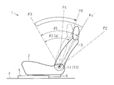
図1に示すように、車両用のシート1は、シートクッション2と、シートクッション2の後端に対して傾動自在に設けられたシートバック3とを備えている。車両の床4には、左右一対のロアレール5と、ロアレール5の長手方向に沿って各ロアレール5上を移動するアッパレール6とが設けられている。シート1は、両アッパレール6上に支持されることにより、車両前後方向における位置調整を可能に構成されている。シート1には、更に、シートバック3の傾倒角度を調整可能なシートリクライニング装置10が設けられている。
図1に示すように、車両用のシート1は、シートクッション2と、シートクッション2の後端に対して傾動自在に設けられたシートバック3とを備えている。車両の床4には、左右一対のロアレール5と、ロアレール5の長手方向に沿って各ロアレール5上を移動するアッパレール6とが設けられている。シート1は、両アッパレール6上に支持されることにより、車両前後方向における位置調整を可能に構成されている。シート1には、更に、シートバック3の傾倒角度を調整可能なシートリクライニング装置10が設けられている。
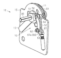
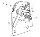
図2~図6に示すように、シートクッション2とシートバック3との間には、リクライナ11が介在されている。リクライナ11は、シートクッション2に対するシートバック3の回動を規制し、及びその回動を許容する。車両の乗員は、シートクッション2の側方に配置される操作ハンドル13を操作することで、リクライナ11によりシートバック3の傾倒角度を調整することができる。
図2に示すように、シートクッション2の骨格を形成するサイドフレーム14の後端から、板状部材としての支持プレート15が上方に延びている。シートバック3の骨格を形成するシートバックサイドメンバ16は、シートクッション2の側方(図2の紙面に直交する方向の手前)に設けられた各支持プレート15の内側(奥側)に配置されている。リクライナ11は、シート1の幅方向に対向して配置される支持プレート15の上端とシートバックサイドメンバ16の基端との間に挟み込まれている。リクライナ11は、シートバック3の幅方向の両側に設けられている。
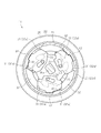
図6~図8に示すように、リクライナ11は、共通の回動中心である回動軸Lを有しかつ相対回動可能に並置された第1及び第2の回動部材(アッパブラケット及びロアブラケット)21,22を備えている。
第1及び第2の回動部材21,22は、ともに略円盤状の外形を有している。第1及び第2の回動部材21,22の周縁には、円環状の周壁部23,24がそれぞれ形成されている。周壁部23は、第1の回動部材21の本体部21aから第2の回動部材22の本体部22aに向かって突出する。周壁部24は、第2の回動部材22の本体部22aから第1の回動部材21の本体部21aに向かって突出する。第1及び第2の回動部材21,22は、互いの周壁部23,24が嵌合することにより、相対回動可能な状態で同軸位置に配置される。
第1の回動部材21は、第1及び第2の回動部材21,22の最外周部に位置する第2の回動部材22の周壁部24に対して段違いに配置された第1及び第2の周壁部23a,23bを備えている。第1及び第2の周壁部23a,23bのうち、径方向外側に位置する第1の周壁部23aの外径は、第2の回動部材22の周壁部24の内径と略等しい。これにより、第1の回動部材21は、第1の周壁部23aが第2の回動部材22の周壁部24に摺接する状態で、第2の回動部材22に対して回動することが可能である。
リクライナ11は、環状ホルダ25を備えている。環状ホルダ25は、第1の回動部材21の第1の周壁部23a及び第2の回動部材22の周壁部24を厚み方向(図6の左右方向)に挟み込み可能な断面形状を有している。環状ホルダ25は、第1及び第2の回動部材21,22の外周に嵌着されることにより、第1及び第2の回動部材21,22間の相対回動を許容しつつ、回動軸Lに沿った相対移動を規制する。
図6に示すように、第1の回動部材21は、シートバックサイドメンバ16の基端に固定され、第2の回動部材22は、シートクッション2の支持プレート15の上端に固定されている。第1及び第2の回動部材21,22の間には、両者に係合することにより第1及び第2の回動部材21,22間の相対回動を規制する3つのロック部材(ポール)30が介在されている。
図6~図8に示すように、第2の回動部材22は、周壁部24の径方向内側に、係合部材としての各ロック部材30を径方向へ移動可能に保持するガイド部31を備えている。
各ロック部材30は、板状に形成されている。また、第1の回動部材21に対して回動軸Lの軸線方向に対向する第2の回動部材22の対向面22s(図6の左側の面)には、3つの保持突部32が形成されている。各保持突部32は、周方向に略均等間隔で配置されている。各保持突部32は、略扇形に形成されている。これにより、周方向に隣り合う保持突部32の側壁部32aが全て略平行となる。各ロック部材30は、隣り合う保持突部32間にそれぞれ配置されている。
各ロック部材30は、板状に形成されている。また、第1の回動部材21に対して回動軸Lの軸線方向に対向する第2の回動部材22の対向面22s(図6の左側の面)には、3つの保持突部32が形成されている。各保持突部32は、周方向に略均等間隔で配置されている。各保持突部32は、略扇形に形成されている。これにより、周方向に隣り合う保持突部32の側壁部32aが全て略平行となる。各ロック部材30は、隣り合う保持突部32間にそれぞれ配置されている。
即ち、周方向に隣り合う保持突部32の側壁部32a間にロック部材30を挟み込むことによって、各保持突部32の側壁部32aは、ガイド部31として機能する。これにより、各ロック部材30は、周方向に隣り合う各保持突部32の側壁部32aに摺接する状態で径方向に移動可能に、第2の回動部材22に保持される。また、各ロック部材30は、各側壁部32aとの当接により周方向への相対移動が規制された状態で、第2の回動部材22に保持される。
図7に示すように、第1の回動部材21の周壁部23の第1の周壁部23aには、円環状をなす内周の全域に亘って、径方向内側に突出する内歯33が形成されている。更に、第2の回動部材22に保持された状態で径方向外側に臨む各ロック部材30の先端には、第1の周壁部23aの内歯33に噛合可能な外歯34が形成されている。各ロック部材30の外歯34が第1の回動部材21の内歯33に噛合することにより、各ロック部材30を保持する第2の回動部材22と第1の回動部材21との相対回転が規制される。
図2~図6に示すように、シートリクライニング装置10は、操作ハンドル13が固定された操作軸40を備えている。操作軸40は、操作ハンドル13と一体に回動する。
図6~図8に示すように、操作軸40は、リクライナ11を厚み方向に貫通している。操作軸40は、第1及び第2の回動部材21,22の本体部21a,22aにおける中央部分を貫通している。リクライナ11は、操作軸40に対して相対回転不能に固定されたカム部材35を備えている。操作軸40は、二面幅状に形成され、平行である一対の平面部を有している。カム部材35は、二面幅形状を有する嵌合孔35aを有している。操作軸40が嵌合孔35aを挿通されることにより、カム部材35は、操作軸40に対して回転不能な状態で固定される。
図6~図8に示すように、操作軸40は、リクライナ11を厚み方向に貫通している。操作軸40は、第1及び第2の回動部材21,22の本体部21a,22aにおける中央部分を貫通している。リクライナ11は、操作軸40に対して相対回転不能に固定されたカム部材35を備えている。操作軸40は、二面幅状に形成され、平行である一対の平面部を有している。カム部材35は、二面幅形状を有する嵌合孔35aを有している。操作軸40が嵌合孔35aを挿通されることにより、カム部材35は、操作軸40に対して回転不能な状態で固定される。
カム部材35は、周縁部分を各ロック部材30の基端に当接させた状態で、各ロック部材30の径方向内側に配置されている。リクライナ11は、カム部材35の回動に基づき各ロック部材30が径方向に移動することにより、各ロック部材30の外歯34が第1の回動部材21の内歯33に係脱するように構成されている。
カム部材35は、上記のように各ロック部材30を保持する第2の回動部材22に対して、図7及び図8の時計回り方向に回動することにより、各ロック部材30を径方向外側に移動させる。これにより、リクライナ11は、各ロック部材30の外歯34が第1の回動部材21の内歯33に噛合することで、第1及び第2の回動部材21,22を相対回動不能に拘束し、シートクッション2に対するシートバック3の傾倒角度を固定するロック状態に切り替える。
一方、カム部材35は、図7及び図8の反時計回り方向に回動することにより、各ロック部材30を径方向内側に移動させる。これにより、リクライナ11は、各ロック部材30の外歯34が第1の回動部材21の内歯33から脱離することで、第1及び第2の回動部材21,22間の相対回動を許容し、シートバック3の傾倒角度を調整可能なアンロック状態に切り替える。
カム部材35の回動軸である操作軸40は、図示しない捩りコイルバネの弾性力により、図7及び図8の時計回り方向であるロック方向に付勢されている。また、操作軸40は、シートクッション2の側方に配置された操作ハンドル13を引き上げることで(図2の時計回り方向への回動操作)、図7及び図8の反時計回り方向であるアンロック方向に回動する。操作ハンドル13の引き上げ操作を中止すると、操作軸40は、捩りコイルバネの弾性力に基づいてロック方向に回動する。
図8に示すように、第1の回動部材21の第2の周壁部23bの内周には、3つの制御突部41が設けられている。各制御突部41は、均等角度間隔で周方向に配置されている。各ロック部材30には、第2の周壁部23bの内周に向かって径方向外側に突出する係合突部42が設けられている。リクライナ11は、各制御突部41と各係合突部42とが当接することにより、各ロック部材30のロック及びアンロック動作を制御する。
リクライナ11は、各ロック部材30のアンロック動作時、係合突部42が第2の周壁部23bの各制御突部41よりも径方向内側に移動するように構成されている。これにより、アンロック状態においては、各ロック部材30の係合突部42と第2の周壁部23bの各制御突部41とが干渉することなく、第1及び第2の回動部材21,22が相対回動可能である。
また、第1及び第2の回動部材21,22の相対回動により各制御突部41及び係合突部42の周方向の位置が重複する場合、各制御突部41と各係合突部42とが接することで、各ロック部材30の径方向外側への移動が規制され、各ロック部材30のロック動作が規制される。即ち、リクライナ11は、第2の周壁部23bの各制御突部41及び各ロック部材30の係合突部42の周方向位置が重複しない所定の回動角度範囲内において、各ロック部材30をロック動作させて、第1及び第2の回動部材21,22の相対回動位置を固定する。各制御突部41と各係合突部42とが接する回動角度範囲においては、各ロック部材30のアンロック状態が維持される。
図1に示すように、シートリクライニング装置10は、リクライナ11の機能により、予め設定された基本位置P0を基準に前方へ傾倒した傾倒角度θ1及び後方へ傾倒した傾倒角度θ2の範囲内において、シートバック3の傾倒角度を変更及び固定することが可能である。
また、シート1は、前方側の傾倒角度の調整限界であるアップライト位置P1を超えて、基本位置P0を基準に前方へ傾倒角度θ3だけシートバック3を傾倒可能である(最大前傾位置P3)。本実施形態では、図示しないストッパによって、シートバック3の最大前傾位置P3(傾倒角度θ3)及び最大後傾位置P2(傾倒角度θ2)が規定されている。アップライト位置P1を超えた前方側の傾倒範囲においては、操作ハンドル13の引き上げを持続しなくても、リクライナ11のアンロック状態が維持され、シートバック3の傾倒角度が固定されない。
(ウォークイン&メモリ機能)
次に、シートリクライニング装置10に実装されたウォークイン&メモリ機能について説明する。
次に、シートリクライニング装置10に実装されたウォークイン&メモリ機能について説明する。
図2~図5に示すように、シートリクライニング装置10は、操作ハンドル13とは独立に、操作軸40をアンロック方向(図2の時計回り方向)に回動させることが可能なウォークインレバー50を備えている。また、図6に示すように、シート1には、シートバック3を前方に付勢する渦巻きバネ等の付勢部材45が設けられている。これにより、シートリクライニング装置10は、操作ハンドル13の引き上げ操作に依らず、シートバック3とシートクッション2との間に設けられたリクライナ11をアンロック状態にして、シートバック3を最大前傾位置P3に傾倒させることが可能なウォークイン機能を有している。
図2~図5、及び図9に示すように、ウォークインレバー50は、操作軸40が挿通される挿通孔51を有している。ウォークインレバー50の先端には、ワイヤーケーブル52が接続されている。ウォークインレバー50は、ワイヤーケーブル52に牽引されることにより、挿通孔51に挿通された操作軸40を回動中心としてアンロック方向(図2及び図9の時計回り方向)に回動する。
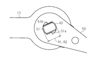
図9に示すように、挿通孔51は、二面幅形状を有する操作軸40の直径(略矩形状断面の長手方向の寸法)R1と略等しいか、それよりも僅かに大きい内径R2を有している。挿通孔51の内周には、一対の係合突部51a,51bが設けられている。ウォークインレバー50がアンロック方向に回動した場合にのみ、一対の係合突部51a,51bは、操作軸40に係合して、操作軸40をウォークインレバー50と一体に回動させる。
図1に示すように、シートバック3の上端には、シート1の後方から操作可能なウォークインハンドル53が設けられている。ワイヤーケーブル52の他端は、ウォークインハンドル53に接続されている。
即ち、シートリクライニング装置10は、ウォークインハンドル53に対する操作入力がワイヤーケーブル52を介してウォークインレバー50に伝達されることにより、挿通孔51内に挿通された操作軸40と一体にウォークインレバー50がアンロック方向に回動するように構成されている。また、操作軸40に固定された操作ハンドル13が引き上げられた場合、挿通孔51の内周に設けられた各係合突部51a,51bは、操作軸40の二面幅形状に係合しない。このため、シートリクライニング装置10は、操作ハンドル13の引き上げによる通常のリクライニング操作時には、ウォークインレバー50の回動を伴うことなく、挿通孔51内に挿通された操作軸40がアンロック方向に回動するように構成されている。
また、図2~図5、及び図10に示すように、シートリクライニング装置10は、リクライナ11を構成する第1の回動部材21の外面に摩擦により係合する第1メモリ部材61と、第1メモリ部材61に対して係脱可能に設けられた第2メモリ部材62とを備えている。
図6に示すように、第1メモリ部材61は、第1の回動部材21の周壁部23に嵌着されている。第1メモリ部材61は、周壁部23との摩擦係合力に基づき第1の回動部材21と同軸に一体回動可能であり、周壁部23との摩擦係合力に抗しつつ第1の回動部材21に対して回動可能である。
第1及び第2の回動部材21,22は、板状の金属材料を塑性加工(プレス加工)することにより形成されている。このため、本体部21a,22aと周壁部23,24とが一体に形成されている。
例えば、第1の回動部材21の第1の周壁部23aを形成する際、塑性変形により第1の回動部材21の内面S1から外面S2(図6の右側から左側)に押し出された段差部分が、第2の周壁部23bの外周として形成される。更に、複数の制御突部41を形成した内周を有する第2の周壁部23bを形成する際、塑性変形によって外面S2に向けて押し出された段差部分が、第3の周壁部23cとして形成される。第1メモリ部材61は、第1の回動部材21の第3の周壁部23cの外周面に嵌合される。
一方、図5及び図6に示すように、第2メモリ部材62は、略四角軸状の外形を有している。また、第2の回動部材22が固定された支持プレート15には、第2メモリ部材62が挿通されるガイド孔63が設けられている。ガイド孔63は、リクライナ11の径方向、即ち、図2及び図6の上下方向に延びる長孔形状を有している。第2メモリ部材62は、ガイド孔63内を移動可能な状態で支持されている。図10に示すように、第1メモリ部材61には、ガイド孔63内を移動する第2メモリ部材62が係脱可能な係合溝65が形成されている。
図2~図6に示すように、ガイド孔63は、支持プレート15に設けられた貫通孔66に筒状部材67を嵌着することにより形成される。筒状部材67は、板状部材である支持プレート15の厚みD0よりも大きな軸方向長さD1を有している。これにより、筒状部材67の周壁67aは、ガイド孔63の周縁において支持プレート15の厚み方向に突出する支持壁68として機能する。
また、図2~図5に示すように、シートリクライニング装置10は、第2メモリ部材62とウォークインレバー50とを連結するリンク部材64を備えている。図11及び図12に示すように、リンク部材64は、ウォークインレバー50がアンロック方向(図11及び図12の時計回り方向)に回動することにより、ガイド孔63内の第2メモリ部材62がリクライナ11の径方向外側、即ち、第1メモリ部材61から離間する方向(図11及び図12の下側)へ移動するように構成されている。これにより、第1メモリ部材61に対して第2メモリ部材62を係脱させるとともに、第2メモリ部材62の係脱動作に連動して各ロック部材30をロック及びアンロック動作させる操作機構70が形成される。
図10に示すように、第1メモリ部材61は、周方向の一部が破断した円環形状(Cリング形状)を有する摩擦係合部71を備えている。摩擦係合部71の内周には、複数の摺接突部72が形成されている。第1メモリ部材61は、各摺接突部72を第1の回動部材21に摺接させ、かつ摩擦係合部71を第1の回動部材21の周壁部23(23c)に嵌合させることにより、第1の回動部材21との間に適切な摩擦係合力を発生させる。
また、第1メモリ部材61は、破断部71xの近傍に周方向端部73aを有する弧状延設部73を備えている。弧状延設部73は、摩擦係合部71から径方向外側に突出している。第1メモリ部材61は、更に、摩擦係合部71から径方向外側に突出する突出部74を備えている。突出部74と第1メモリ部材61と弧状延設部73の周方向端部73aとの間には、破断部71xが設けられている。
第1メモリ部材61の係合溝65は、突出部74の側面74a及び弧状延設部73の周方向端部73aを、周方向に対向して配置される一対の側壁面65sとして備えている。破断部71xは、摩擦係合部71の第1端71aと第2端71bとの間に設けられ、係合溝65は、第1端71a近傍の側壁面65sと第2端71b近傍の側壁面65sとを有している。第1メモリ部材61の係合溝65に第2メモリ部材62が挿入されて係合することにより、第2の回動部材22に対する第1メモリ部材61の回動が規制される。
具体的には、図11に示すように、ウォークインハンドル53が操作されていない場合、第2メモリ部材62は、支持プレート15のガイド孔63内における第1メモリ部材61の径方向内側(図11の上側)に配置され、第1メモリ部材61の係合溝65内に挿入されている。これにより、第1メモリ部材61に第2メモリ部材62が係合し、支持プレート15に固定された第2の回動部材22に対する第1メモリ部材61の回動が規制される。
この状態で、シートクッション2の側方に設けられた操作ハンドル13(図2参照)を引き上げた場合、ウォークインレバー50は回動せず、第1メモリ部材61に対する第2メモリ部材62の係合状態は維持される。しかしながら、第1の回動部材21は、操作ハンドル13の引き上げにより各ロック部材30がアンロック動作するため、第1メモリ部材61との摩擦係合力に抗して、第2の回動部材22に対して回動可能となる。こうして、操作ハンドル13を用いた通常のリクライニング操作によって、シートバック3の傾倒角度を調整することは可能である。
一方、図12に示すように、ウォークインハンドル53(図1参照)が操作された場合、ウォークインレバー50がアンロック方向に回動するため、第2メモリ部材62は、支持プレート15のガイド孔63内を第1メモリ部材61の径方向外側(図12の下側)に向かって移動する。これにより、係合溝65から第2メモリ部材62が抜脱され、第2メモリ部材62と第1メモリ部材61との係合が解除されるため、第2の回動部材22に対する第1メモリ部材61の回動が可能となる。
また、このとき、リクライナ11においては、操作機構70のウォークインレバー50の回動に伴い各ロック部材30がアンロック動作(脱離動作)するため、第1及び第2の回動部材21,22間の相対回動が許容される。これにより、摩擦係合力に基づいて、第1の回動部材21と第1メモリ部材61との一体回動が可能となる。
ここで、図10、図13及び図14に示すように、第1メモリ部材61の弧状延設部73の外周部には、摺接面75が形成されている。シートバック3の傾動に伴い第1の回動部材21と一体に第1メモリ部材61が回動した場合、第2メモリ部材62は、係合溝65から脱離した後、摺接面75に摺接する。これにより、ウォークインハンドル53に対する操作入力を持続することなく、シートバック3を最大前傾位置P3まで傾倒させることができる。
即ち、シートバック3は、付勢部材45(図6参照)により付勢された状態で、シートバック3とシートクッション2との間のリクライナ11がアンロック状態となるため、前方へ傾動する。このとき、第1メモリ部材61が第1の回動部材21と一体に回動することで、第2メモリ部材62が第1メモリ部材61の摺接面75に摺接する。これにより、第1メモリ部材61の径方向内側に向かう第2メモリ部材62の係合動作が規制されるため、図13及び図14の反時計回り方向へのウォークインレバー50の回動、及び各ロック部材30のロック動作が規制される。これにより、リクライナ11のアンロック状態が維持されるため、シートバック3が付勢部材45により付勢されて、最大前傾位置P3に到達する。
また、ウォークイン機能により前倒し操作されたシートバック3を引き起こす場合も、第1メモリ部材61の摺接面75に第2メモリ部材62が摺接している限り、リクライナ11のアンロック状態は維持される。
即ち、シートバック3の引き起こし操作時、第2メモリ部材62は、摩擦係合力に基づき第1の回動部材21と第1メモリ部材61とが一体回動することで、第1メモリ部材61の摺接面75上を周方向に、係合溝65に挿入可能な位置まで移動する。これにより、シートバック3を前倒し操作前の傾倒位置に復帰させることが可能なメモリ機能が実現される。
図10に示すように、第1メモリ部材61の突出部74の先端は、突出部74とともに係合溝65の両側壁面65sを構成する弧状延設部73の摺接面75よりも、径方向外側に突出している。
図12に示すように、突出部74は、第1及び第2の回動部材21,22の相対回動を伴いつつシートバック3が後方に傾倒する場合、第1の回動部材21と一体に第1メモリ部材61が回動することで、第2の回動部材22の支持プレート15近傍の第2メモリ部材62に当接する。具体的には、突出部74は、係合溝65に第2メモリ部材62を挿入可能な第1相対回動位置Q1において、第2メモリ部材62に当接する。突出部74がストッパ部76として機能することにより、摩擦係合力に基づいた第1の回動部材21と第1メモリ部材61との一体回動が規制される。
また、図10に示すように、第1メモリ部材61の弧状延設部73は、係合溝65と反対側の周方向端部73b近傍に、第2突出部77を有している。第2突出部77の先端は、突出部74と同様、弧状延設部73の摺接面75よりも径方向外側に突出している。
図14に示すように、第2突出部77も、第1及び第2の回動部材21,22の相対回動を伴いつつシートバック3が前方に傾倒する場合、第1の回動部材21と一体に第1メモリ部材61が回動することで、第2の回動部材22近傍の第2メモリ部材62に当接する。第2突出部77は、見かけ上、摺接面75上を周方向に移動する第2メモリ部材62が摺接面75の末端に到達する第2相対回動位置Q2において、第2メモリ部材62に当接する。第2突出部77がストッパ部78として機能することにより、摩擦係合力に基づいた第1の回動部材21と第1メモリ部材61との一体回動が規制される。
ストッパ部78を構成する第2突出部77に第2メモリ部材62が当接した後も、付勢部材45の付勢力に基づきシートバック3が最大前傾位置P3に到達できるように、第1の回動部材21の周壁部23に対する第1メモリ部材61の摩擦係合力が設定されている。図1及び図10に示すように、第1メモリ部材61に設定された第1相対回動位置Q1及び第2相対回動位置Q2間の相対回動角度αは、シートバック3に設定された基本位置P0から最大前傾位置P3に至るまでの傾倒角度θ3に等しく設定されている。
即ち、図15に示すように、前倒し操作前におけるシートバック3の傾倒位置Pxが基本位置P0とアップライト位置P1との間にある場合、前倒し操作によりシートバック3が最大前傾位置P3に到達するまでの傾倒角度θ4は、基本位置P0から最大前傾位置P3までの傾倒角度θ3よりも小さい(θ4<θ3)。傾倒角度θ4は、第1メモリ部材61に設定された第1相対回動位置Q1及び第2相対回動位置Q2間の相対回動角度αよりも小さい。
従って、このような前傾状態から前倒し操作を開始した場合、第2メモリ部材62が第2突出部77に当接する摺接面75の末端まで到達しないため、第1の回動部材21に摩擦係合する第1メモリ部材61の相対回動位置が維持される。これにより、前倒し操作されたシートバック3を後方に引き起こすことで、シートバック3が前倒し操作前の傾倒位置Pxに復帰する。
一方、図16に示すように、前倒し操作前におけるシートバック3の傾倒位置Px´が基本位置P0よりも後方にある場合、前倒し操作によりシートバック3が最大前傾位置P3に到達するまでの傾倒角度θ5は、基本位置P0から最大前傾位置P3までの傾倒角度θ3よりも大きい(θ5>θ3)。この傾倒角度θ5は、第1メモリ部材61に設定された第1相対回動位置Q1及び第2相対回動位置Q2間の相対回動角度αよりも大きい。
従って、このような後傾状態から前倒し操作を開始した場合、第2メモリ部材62が第2突出部77に当接し、第2突出部77がストッパ部78として機能することにより、摩擦係合力に基づいた第1の回動部材21と第1メモリ部材61との一体回動が規制される。第2突出部77に第2メモリ部材62が当接した後、付勢部材45の付勢力に基づきシートバック3が最大前傾位置P3に到達することにより、第1の回動部材21と第1メモリ部材61との相対回動位置が修正される。
即ち、この修正により、第2の回動部材22に対する第1メモリ部材61の相対回動角度が、第1相対回動位置Q1及び第2相対回動位置Q2間に設定された相対回動角度αに一致する。これにより、前倒し操作されたシートバック3を後方に引き起こすことで、シートバック3が基本位置P0に復帰する。
(第2メモリ部材の支持構造)
次に、本実施形態のシートリクライニング装置10における第2メモリ部材62の支持構造について詳述する。
次に、本実施形態のシートリクライニング装置10における第2メモリ部材62の支持構造について詳述する。
図17(a),17(b)に示すように、本実施形態の第2メモリ部材62には、断面略正方形状に形成された軸部83が設けられている。軸部83は、上記支持プレート15に設けられたガイド孔63に挿通され、当該ガイド孔の長手方向に沿って移動可能な状態で支持される。これにより、第2メモリ部材62は、第1メモリ部材61に対して係脱動作することが可能となっている。
即ち、本実施形態の第2メモリ部材62は、軸部83がガイド孔63に案内されることにより第1メモリ部材61に対して接離方向に移動する。軸部83の軸幅W1(正方形状断面における一辺の長さ)は、その長孔状に形成されたガイド孔63の溝幅W0(短手方向長さ)と略等しい値に設定されている。これにより、溝幅方向(図17中、左右方向)に位置する軸部83の二面83a,83bが、ガイド孔63を画定する両内側壁面63a,63bに対して摺接する。両内側壁面63a,63bは、ガイド孔63の短手方向両側に位置するとともにガイド孔63の長手方向に延びている。
具体的には、軸部83の二面83a,83bは、両内側壁面63a,63b及び当該両内側壁面63a,63bに連続する支持壁68の内壁面68sに対して面接触する。そして、本実施形態のシートリクライニング装置10は、これにより、そのガイド孔63の長手方向に移動する第2メモリ部材62の傾動を抑制する。
以上、本実施形態によれば、以下のような効果を得ることができる。
(1)シートリクライニング装置10は、第1の回動部材21と、第1の回動部材21と同軸に並置された第2の回動部材22と、第1及び第2の回動部材21,22間の相対回動を規制するロック部材30とを備える。シートリクライニング装置10は、第1メモリ部材61と、第1メモリ部材61に対して係脱可能な第2メモリ部材62とを備える。第1メモリ部材61は、第1の回動部材21の外面S2に摩擦係合することにより、第1の回動部材21と同軸に一体回動可能であり、且つ摩擦係合力に抗して第1の回動部材21に対し回動可能である。更に、シートリクライニング装置10は、第2メモリ部材62を係脱動作させるとともに、その係脱動作に連動してロック部材30をロック及びアンロック動作させることが可能な操作機構70を備える。また、第1メモリ部材61には、摺接面75が設けられる。摺接面75は、第2メモリ部材62と摺接することにより、ロック部材30のロック動作を伴う第2メモリ部材62の係合動作を規制する。更に、第1メモリ部材61には、係合溝65が設けられる。第1メモリ部材61が第2の回動部材22に対して所定の相対回動位置(第1相対回動位置Q1)にある場合、係合溝65に対する第2メモリ部材62の係合動作が許容され、それにより、第2メモリ部材62が係合溝65に挿入及び係合される。即ち、シートリクライニング装置10は、第2の回動部材22に対する第1メモリ部材61の相対回動を規制可能に構成されている。
(1)シートリクライニング装置10は、第1の回動部材21と、第1の回動部材21と同軸に並置された第2の回動部材22と、第1及び第2の回動部材21,22間の相対回動を規制するロック部材30とを備える。シートリクライニング装置10は、第1メモリ部材61と、第1メモリ部材61に対して係脱可能な第2メモリ部材62とを備える。第1メモリ部材61は、第1の回動部材21の外面S2に摩擦係合することにより、第1の回動部材21と同軸に一体回動可能であり、且つ摩擦係合力に抗して第1の回動部材21に対し回動可能である。更に、シートリクライニング装置10は、第2メモリ部材62を係脱動作させるとともに、その係脱動作に連動してロック部材30をロック及びアンロック動作させることが可能な操作機構70を備える。また、第1メモリ部材61には、摺接面75が設けられる。摺接面75は、第2メモリ部材62と摺接することにより、ロック部材30のロック動作を伴う第2メモリ部材62の係合動作を規制する。更に、第1メモリ部材61には、係合溝65が設けられる。第1メモリ部材61が第2の回動部材22に対して所定の相対回動位置(第1相対回動位置Q1)にある場合、係合溝65に対する第2メモリ部材62の係合動作が許容され、それにより、第2メモリ部材62が係合溝65に挿入及び係合される。即ち、シートリクライニング装置10は、第2の回動部材22に対する第1メモリ部材61の相対回動を規制可能に構成されている。
上記構成によれば、第1メモリ部材61の係合溝65内に第2メモリ部材62が挿入された状態においても、第1メモリ部材61の摩擦係合力に抗して、第1の回動部材21を第2の回動部材22に対して回動させることができる。これにより、第1メモリ部材61に対する第2メモリ部材62の係脱動作を伴わない通常のリクライニング操作によって、シートバック3の傾倒角度を調整することができる。
また、係合溝65から第2メモリ部材62が抜脱されると、第1メモリ部材61は、摩擦係合力に基づいて第1の回動部材21と一体回動可能な状態となる。即ち、第1及び第2の回動部材21,22が相対回動することにより、第1メモリ部材61の摺接面75が第2メモリ部材62に摺接し、ロック部材30のロック動作を伴う第2メモリ部材62の係合動作が規制される。その結果、シートバック3の傾倒角度が固定されないアンロック状態が維持される。これにより、操作機構70を介したアンロック操作を持続することなく、シートバック3を最大傾倒位置まで傾倒させることができる。
更に、傾倒したシートバック3を引き起こす場合、第1の回動部材21と一体回動する第1メモリ部材61が、第2の回動部材22に対する第1相対回動位置Q1に復帰することにより、係合溝65に第2メモリ部材62を挿入可能な状態となる。これにより、ロック部材30のロック動作を伴う第2メモリ部材62の係合動作が許容されるため、傾倒操作前の傾倒位置Pxにおいて、シートバック3の傾倒角度を固定することができる。
また、上記構成は、各メモリ部材を第1及び第2の回動部材21,22の間に配置するリクライナ内蔵型の構成と比較して、より優れた組付け性を有している。また、空間的な配置自由度の高さを活かして装置の薄型化や高精度のロック及びアンロック動作が行えるという利点を有している。
(2)摺接面75は、第1及び第2の回動部材21,22の相対回動を伴いつつシートバック3が前方に傾倒するときに摩擦係合力に基づき第1メモリ部材61が第1の回動部材21と一体回動することで第2メモリ部材62に摺接する位置に、形成される。
上記構成によれば、ロック部材30のロック動作を伴う第2メモリ部材62の係合動作が規制され、アンロック状態が維持されることにより、操作機構70を介したアンロック操作を維持することなく、シートバック3を最大前傾位置P3まで傾倒させることができる。
(3)第1メモリ部材61は、突出部74を備える。第1及び第2の回動部材21,22間の相対回動を伴いつつシートバック3が後方に傾倒する場合、突出部74は、係合溝65に第2メモリ部材62を挿入可能な第1相対回動位置Q1において、第2メモリ部材62に当接する。突出部74がストッパ部76として機能することにより、摩擦係合力に基づく第1の回動部材21と第1メモリ部材61との一体回動を規制することができる。
上記構成によれば、前倒し操作されたシートバック3を引き起こす場合、係合溝65に対して第2メモリ部材62を挿入可能な第1相対回動位置Q1に第1メモリ部材61が到達したとき、第1メモリ部材61と第1の回動部材21との間の摩擦係合力に基づいて、シートバック3に抵抗感(手応え)を与えることができる。これにより、シートバック3の傾倒角度を固定可能な状態にあることが示されるため、優れた操作性を確保することができる。
また、ロック部材30のアンロック動作を伴いつつ第1メモリ部材61から第2メモリ部材62が脱離した場合、シートバック3が後方に傾倒することを抑制することができる。これにより、シートバック3の前倒し操作を誘導することができ、ウォークイン機能を担保することができる。
(4)第1メモリ部材61は、第2突出部77を備える。第1及び第2の回動部材21,22間の相対回動を伴いつつシートバック3が前方に傾倒する場合、第2突出部77は、係合溝65に第2メモリ部材62を挿入可能な第1相対回動位置Q1から所定の相対回動角度αに設定された第2相対回動位置Q2において、第2メモリ部材62に当接する。第2突出部77がストッパ部78として機能することにより、摩擦係合力に基づく第1の回動部材21と第1メモリ部材61との一体回動を規制することができる。
即ち、シートバック3の前倒し操作により第2突出部77に対して第2メモリ部材62が当接した後も、第1の回動部材21は、第1メモリ部材61との摩擦係合力に抗することで第2の回動部材22に対して回動可能である。従って、上記構成によれば、第2突出部77に対する第2メモリ部材62の当接後、前倒し操作されたシートバック3が最大前傾位置P3に到達することで、第1の回動部材21と第1メモリ部材61との相対回動位置が修正される。これにより、第1メモリ部材61と第2の回動部材22との相対回動角度が第1相対回動位置Q1及び第2相対回動位置Q2間に設定された所定の相対回動角度αに一致することで、最大前傾位置P3から引き起こされたシートバック3は、所定の相対回動角度αに対応する所定の傾倒位置に復帰することができる。
つまり、所定の相対回動角度αをシートバック3の基本位置P0から最大前傾位置P3に到達するまでの傾倒角度θ3に等しく設定することで、基本位置P0よりも前方の傾倒位置Pxから前倒し操作を開始した場合、最大前傾位置P3から引き起こされたシートバック3が前倒し操作前の傾倒位置Pxに復帰する。また、基本位置P0よりも後方の傾倒位置Px´から前倒し操作を開始した場合、最大前傾位置P3から引き起こされたシートバック3が基本位置P0に復帰する。これにより、引き起こされたシートバック3が後部シートに着座した乗員に干渉しないため、利便性を高めることができる。
(5)シートバック3は、付勢部材45により前方に付勢される。第1の回動部材21に対する第1メモリ部材61の摩擦係合力は、ストッパ部78を構成する第2突出部77に対する第2メモリ部材62の当接後も、付勢部材45の付勢力に基づいて第1及び第2の回動部材21,22が相対回動するように設定される。
上記構成によれば、シートバック3の前倒し操作を、より容易に行うことができる。また、第2突出部77に対する第2メモリ部材62の当接後、付勢部材45の付勢力に基づきシートバック3が最大前傾位置P3に到達することにより、前倒し操作されたシートバック3を基本位置P0へ安定的に復帰させることができる。
(6)第2メモリ部材62は、板状部材としての支持プレート15に設けられた長孔状のガイド孔63に挿通される軸部83を有している。該軸部83は、ガイド孔63の長手方向に沿って移動可能な状態で支持される。これにより、第2メモリ部材62は、第1メモリ部材61に対して係脱動作可能に構成される。そして、ガイド孔63の周縁部には、支持プレート15の厚み方向に突出する支持壁68が設けられる。
上記構成によれば、その支持壁68に軸部83が当接することで、より安定的に第2メモリ部材62を支持することができる。そして、これにより、第2メモリ部材62の傾動を抑制することで、より正確に第2メモリ部材62を係脱動作させることができる。
(7)ガイド孔63は、該ガイド孔63の短手方向両側に位置するとともにガイド孔63の長手方向に延びる一対の内側壁面63a,63bによって画定されている。支持壁68は、内側壁面63a,63bの各々に連続して設けられる。これにより、より安定的に、そのガイド孔63の長手方向に移動する第2メモリ部材62を支持することができる。
(8)ガイド孔63は、該ガイド孔63の短手方向両側に位置するとともにガイド孔63の長手方向に延びる一対の内側壁面63a,63bによって画定されている。第2メモリ部材62の軸部83は、ガイド孔63を画定する内側壁面63a,63bに対して面接触状態で摺接する二面83a,83bを有する。このような構成とすることで、より安定的に、そのガイド孔63の長手方向に移動する第2メモリ部材62を支持することができる。
(9)支持壁68は、支持プレート15に形成された貫通孔66に筒状部材67を嵌着することによりガイド孔63と一体に形成される。このような構成を採用することにより、最適なガイド孔63及び支持壁68を容易に形成することができる。即ち、ガイド孔63として機能している筒状部材67の筒内に第2メモリ部材62の軸部83を挿入する。これにより、筒状部材67の周壁67aが支持壁68として機能する。そして、これにより、より安定的に第2メモリ部材62を支持することができる。
なお、上記実施形態は以下のように変更してもよい。
・支持壁68は、支持プレート15に形成された貫通孔66に筒状部材67を嵌着することによりガイド孔63と一体に形成される構成に限られない。例えば、図18(a),18(b)に示すように、支持プレート15を塑性加工(折曲加工等)することによりガイド孔63の周縁部に支持壁68を形成してもよい。或いは、支持プレート15に形成されたガイド孔63の周縁部に支持壁68となる別部材を固定してもよい。
・支持壁68は、支持プレート15に形成された貫通孔66に筒状部材67を嵌着することによりガイド孔63と一体に形成される構成に限られない。例えば、図18(a),18(b)に示すように、支持プレート15を塑性加工(折曲加工等)することによりガイド孔63の周縁部に支持壁68を形成してもよい。或いは、支持プレート15に形成されたガイド孔63の周縁部に支持壁68となる別部材を固定してもよい。
・また、支持壁68は、少なくとも、ガイド孔63を画定する両内側壁面63a,63b近傍の周縁部分に位置していることが好ましい。支持壁68は、両内側壁面63a,63bに沿って延びていることが好ましい。そして、その支持壁68は、これらの各内側壁面63a,63bに連続していることが好ましい。
・第2メモリ部材62の軸部83は、断面略正方形をなす角軸状に形成されてガイド孔63に挿通される構成に限られない。軸部83の断面形状は、任意に変更してもよい。但し、第2メモリ部材62の安定的な支持を考慮した場合、軸部83は、ガイド孔63を画定する両内側壁面63a,63bの双方に摺接することが好ましい。また、軸部83は、内側壁面63a,63bの少なくとも一方に対しては面接触する状態でガイド孔63に挿通されることが好ましい。
・更に、図19(a),19(b)に示すように、ガイド孔63の周縁部に支持壁68が設けられなくてもよい。この構成では、ガイド孔63を画定する両内側壁面63a,63bの双方に摺接するとともに当該各内側壁面63a,63bの少なくとも一方に対しては面接触する状態で第2メモリ部材62の軸部83がガイド孔63に挿通される。そして、この場合には、軸部83がガイド孔63を画定する両内側壁面63a,63bに対して面接触状態で摺接する二面83a,83bを有することが好ましい。
・第1メモリ部材61は、周方向の一部が破断した円環形状(所謂Cリング形状)を有する摩擦係合部71を備えていなくてもよい。例えば、破断部を有しない円環形状等、第1メモリ部材61の形状は任意に変更してもよい。そして、第1の回動部材21との間に摩擦リングを介在させてもよい。
・係合溝65は、摩擦係合部71の第1端71a及び第2端71bに別れて設けられた周方向の両側壁面65sを有していなくてもよい。すなわち、第1メモリ部材61における係合溝65の形成位置は、任意に変更してもよい。
・更に、第1メモリ部材61は、第2メモリ部材62に当接してストッパ部76,78として機能することにより、その摩擦係合力に基づく第1の回動部材21と第1メモリ部材61との一体回動を規制可能な突出部74及び第2突出部77を有していなくてもよい。すなわち、第1メモリ部材61はストッパ部76,78の何れか一方のみを備えていてもよい。本願は、第1メモリ部材61がストッパ部76,78の双方を有しない構成を排除しない。
・摺接面75は、シートバック3を前方に傾倒させた場合に第2メモリ部材62に摺接する位置以外に形成されてもよい。例えば、摺接面75は、シートバック3を後方に傾倒させた場合に第2メモリ部材62に摺接する位置にも形成されてよい。本願は、シートバック3を後方に傾倒させた場合に摺接する位置のみに摺接面75が形成される構成も排除しない。尚、このような構成は、例えば、そのシートバック3をシートクッション2と略水平となるまで「後ろ倒し操作」することが可能な所謂「フラットシート」等に適用するとよい。
・第1メモリ部材61は、周壁部23の第3の周壁部23cに対して嵌合していなくてもよい。上記実施形態では、周壁部23は、第2の回動部材22の周壁部24に対して段違いに設けられている。周壁部24は、第1及び第2の回動部材21,22の最外周部である。具体的には、第1メモリ部材61は、内周に内歯33を有する第1の周壁部23aや、内周に制御突部41を有する第2の周壁部23bに対して嵌合してもよい。そして、第1の回動部材21の周壁部23が第1及び第2の回動部材21,22の最外周部である構成において、この最外周部に第1メモリ部材61が嵌合してもよい。
・また、環状ホルダ25のような第1及び第2の回動部材21,22間の連結部材が第1の回動部材21に固定される構成においては、連結部材が第1の回動部材21の一部であってもよい。或いは、固定部材を介して第1の回動部材21をシートバック側に固定する構成においては、固定部材が第1の回動部材21の一部であってもよい。更に、シートバック側(シートバックサイドメンバ16等)に固定されることにより第1の回動部材21と同軸位置に設けられた保持部材を有する構成においては、保持部材が第1の回動部材21の一部であってもよい。このような場合には、これら連結部材や固定部材、或いは保持部材の外周に第1メモリ部材61が嵌合してもよい。
・上記実施形態では、第1の回動部材21はシートバック側に固定され、第2の回動部材22はシートクッション側に固定される。第1の回動部材21は、周壁部23の内周に内歯33及び制御突部41を有している。第2の回動部材22は、周壁部24の径方向内側に、各ロック部材30を径方向移動可能に保持するガイド部31を有する。しかし、これに限らず、第1の回動部材は、周壁部の径方向内側に各ロック部材を保持するように構成されてもよい。第2の回動部材は、周壁部の内周に内歯及び制御突部を有するように構成されてもよい。即ち、上記実施形態とは表裏を反対にした状態のリクライナ11をシートクッション2とシートバック3との間に介在させてもよい。そして、この場合においてもまた、第1メモリ部材61は、シートバック側の第1の回動部材21に対して摩擦係合するように構成されることは言うまでもない。
・上記実施形態では、第2メモリ部材62は、第1メモリ部材61(リクライナ11)に対して径方向に移動することにより、その係合溝65に対して挿抜される。しかし、これに限らず、第2メモリ部材62の挿入方向(挿抜方向)は、必ずしも第1メモリ部材61の径方向に一致しなくともよい。また、その挿入方向が第1メモリ部材61の回動中心に向かう方向に一致しなくともよい。更に、第1メモリ部材61に係脱する第2メモリ部材62の係脱動作について、必ずしも、その軌跡が直線的である必要はなく、円弧状に湾曲してもよい。そして、係合溝65内に第2メモリ部材62が挿入された後、その「挿入方向」が連続的に変化するように係合溝65の側壁面65sが湾曲していてもよい。
即ち、ガイド孔63の長孔形状は、直線的なものに限らず湾曲した長孔形状であってもよい。そして、この場合においてもまた、第2メモリ部材62の軸部83は、ガイド孔63を画定する両内側壁面63a,63bの双方に摺接するとともに当該各内側壁面63a,63bの少なくとも一方に対しては面接触する状態でガイド孔63に挿通されることが好ましい。
・上記実施形態では、シートバック3の上端部(肩口部分)に設けられたウォークインハンドル53に対する操作入力に基づいて、シート1の後方からシートバック3をウォークイン動作させることが可能である。しかし、これに限らず、操作機構70の操作入力部は、例えば、フットレバー式等であってもよい。すなわち、操作機構70の操作入力部の配置や形状を任意に変更してもよい。
次に、以上の実施形態から把握することのできる技術的思想を効果とともに記載する。
(A)前記摺接面は、前記第1及び第2の回動部材間の相対回動を伴いつつシートバックが前方側に傾倒する際、前記摩擦係合力に基づき前記第1メモリ部材が前記第1の回動部材と一体に回動することにより前記第2メモリ部材に摺接する位置に形成されている、車両用シートリクライニング装置。
(A)前記摺接面は、前記第1及び第2の回動部材間の相対回動を伴いつつシートバックが前方側に傾倒する際、前記摩擦係合力に基づき前記第1メモリ部材が前記第1の回動部材と一体に回動することにより前記第2メモリ部材に摺接する位置に形成されている、車両用シートリクライニング装置。
上記構成によれば、ロック部材のロック動作を伴う第2メモリ部材の係合動作が規制される。その結果、アンロック状態が維持される。これにより、操作機構を介したアンロック操作を持続することなく、シートバックを最大前傾位置まで傾倒させることができる。
(B)前記シートバックは、付勢部材により前方側に付勢されるように構成されており、
前記ストッパ部に前記第2メモリ部材が当接した後に、前記付勢部材の付勢力に基づき前記第1及び第2の回動部材が相対回動するように、前記第1の回動部材に対する前記第1メモリ部材の摩擦係合力が設定されている、車両用シートリクライニング装置。
前記ストッパ部に前記第2メモリ部材が当接した後に、前記付勢部材の付勢力に基づき前記第1及び第2の回動部材が相対回動するように、前記第1の回動部材に対する前記第1メモリ部材の摩擦係合力が設定されている、車両用シートリクライニング装置。
上記構成によれば、より容易に、そのシートバックを前倒し操作することができる。また、ストッパ部に対する第2メモリ部材の当接後、付勢部材の付勢力に基づきシートバックが最大前傾位置に到達することにより、その前倒し操作されたシートバックを、その第1相対回動位置と第2相対位置との間に設定された所定の相対回動角度に対応する所定の傾倒位置に復帰させることができる。
Claims (9)
- 第1の回動部材と、
前記第1の回動部材と同軸に並置された第2の回動部材と、
前記第1及び第2の回動部材間の相対回動を規制するロック部材と、
前記第1の回動部材の外面に摩擦係合することで前記第1の回動部材と同軸に一体回動可能且つ摩擦係合力に抗して相対回動可能な第1メモリ部材と、
前記第1メモリ部材に対して係脱可能な第2メモリ部材と、
前記第2メモリ部材を前記第1メモリ部材に対して係脱動作させるとともに該係脱動作に連動して前記ロック部材をロック及びアンロック動作させる操作機構と、を備え、
前記第1メモリ部材は、
前記第2メモリ部材に摺接することにより前記ロック部材のロック動作を伴う前記第2メモリ部材の係合動作を規制する摺接面と、
前記第1メモリ部材が前記第2の回動部材に対して所定の相対回動位置にある場合に前記第2メモリ部材の係合動作を許容して該係合動作により挿入された前記第2メモリ部材と係合することにより前記第2の回動部材に対する前記第1メモリ部材の相対回動を規制する係合溝と、を有し、
前記操作機構は、板状部材に設けられた長孔状のガイド孔を含み、
前記第2メモリ部材は、前記ガイド孔に挿通される軸部を有し、
前記第2メモリ部材は、前記軸部が前記ガイド孔の長手方向に沿って移動可能な状態で支持されることにより前記第1メモリ部材に対して前記係脱動作するように構成されており、
前記ガイド孔の周縁部には、前記板状部材の厚み方向に突出する支持壁が設けられている
車両用シートリクライニング装置。 - 請求項1に記載の車両用シートリクライニング装置において、
前記ガイド孔は、該ガイド孔の短手方向両側に位置するとともに前記長手方向に延びる一対の内側壁面によって画定されており、
前記支持壁は、前記ガイド孔を画定する前記内側壁面の各々に連続して設けられている、車両用シートリクライニング装置。 - 請求項1に記載の車両用シートリクライニング装置において、
前記ガイド孔は、該ガイド孔の短手方向両側に位置するとともに前記長手方向に延びる一対の内側壁面によって画定されており、
前記第2メモリ部材の軸部は、前記ガイド孔を画定する前記一対の内側壁面に摺接するとともに前記内側壁面の少なくとも一方に対しては面接触する状態で前記ガイド孔に挿通されている、車両用シートリクライニング装置。 - 請求項1~請求項3の何れか一項に記載の車両用シートリクライニング装置において、
前記支持壁は、前記板状部材に形成された貫通孔に筒状部材を嵌着することにより前記ガイド孔と一体に形成されている、車両用シートリクライニング装置。 - 第1の回動部材と、
前記第1の回動部材と同軸に並置された第2の回動部材と、
前記第1及び第2の回動部材間の相対回動を規制するロック部材と、
前記第1の回動部材の外面に摩擦係合することにより該第1の回動部材と同軸に一体回動可能且つ摩擦係合力に抗して相対回動可能な第1メモリ部材と、
前記第1メモリ部材に対して係脱可能な第2メモリ部材と、
前記第2メモリ部材を前記第1メモリ部材に対して係脱動作させるとともに該係脱動作に連動して前記ロック部材をロック及びアンロック動作させる操作機構と、を備え、
前記第1メモリ部材は、
前記第2メモリ部材に摺接することにより前記ロック部材のロック動作を伴う前記第2メモリ部材の係合動作を規制する摺接面と、
前記第1メモリ部材が前記第2の回動部材に対して所定の相対回動位置にある場合に前記第2メモリ部材の係合動作を許容して該係合動作により挿入された前記第2メモリ部材と係合することにより前記第2の回動部材に対する前記第1メモリ部材の相対回動を規制する係合溝と、を有し、
前記操作機構は、板状部材に設けられた長孔状のガイド孔を含み、
前記第2メモリ部材は、前記ガイド孔に挿通される軸部を有し、
前記第2メモリ部材は、前記軸部が前記ガイド孔の長手方向に沿って移動可能な状態で支持されることにより前記第1メモリ部材に対して前記係脱動作するように構成されており、
前記ガイド孔は、該ガイド孔の短手方向両側に位置するとともに前記長手方向に延びる一対の内側壁面によって画定されており、
前記第2メモリ部材の軸部は、前記ガイド孔の前記一対の内側壁面に摺接するとともに前記内側壁面の少なくとも一方に対しては面接触する状態で前記ガイド孔に挿通されている、車両用シートリクライニング装置。 - 請求項1~請求項5の何れか一項に記載の車両用シートリクライニング装置において、
前記第1メモリ部材は、前記第1及び第2の回動部材間の相対回動を伴いつつシートバックが後方側に傾倒する際、前記所定の相対回動位置において前記第2メモリ部材に当接することにより、前記摩擦係合力に基づく前記第1の回動部材との一体回動を規制するストッパ部をさらに有している、車両用シートリクライニング装置。 - 請求項1~請求項6の何れか一項に記載の車両用シートリクライニング装置において、
前記第1メモリ部材は、前記第1及び第2の回動部材間の相対回動を伴いつつシートバックが前方側に傾倒する際、前記係合溝に前記第2メモリ部材を挿入可能な第1相対回動位置から所定の相対回動角度に設定された第2相対回動位置において前記第2メモリ部材に当接することにより、前記摩擦係合力に基づく前記第1の回動部材との一体回動を規制するストッパ部をさらに有している、車両用シートリクライニング装置。 - 請求項1~請求項7の何れか一項に記載の車両用シートリクライニング装置において、
前記摺接面は、前記第1及び第2の回動部材間の相対回動を伴いつつシートバックが前方側に傾倒する際、前記摩擦係合力に基づき前記第1メモリ部材が前記第1の回動部材と一体に回動することにより前記第2メモリ部材に摺接する位置に形成されている、車両用シートリクライニング装置。 - 請求項6に記載の車両用シートリクライニング装置において、
前記シートバックは、付勢部材により前方側に付勢されるように構成されており、
前記ストッパ部に前記第2メモリ部材が当接した後に、前記付勢部材の付勢力に基づき前記第1及び第2の回動部材が相対回動するように、前記第1の回動部材に対する前記第1メモリ部材の摩擦係合力が設定されている、車両用シートリクライニング装置。
Priority Applications (1)
| Application Number | Priority Date | Filing Date | Title |
|---|---|---|---|
| US15/325,641 US20170158092A1 (en) | 2014-07-14 | 2015-07-06 | Seat reclining device for vehicle |
Applications Claiming Priority (2)
| Application Number | Priority Date | Filing Date | Title |
|---|---|---|---|
| JP2014144561A JP6318936B2 (ja) | 2014-07-14 | 2014-07-14 | 車両用シートリクライニング装置 |
| JP2014-144561 | 2014-07-14 |
Publications (1)
| Publication Number | Publication Date |
|---|---|
| WO2016009874A1 true WO2016009874A1 (ja) | 2016-01-21 |
Family
ID=55078372
Family Applications (1)
| Application Number | Title | Priority Date | Filing Date |
|---|---|---|---|
| PCT/JP2015/069430 Ceased WO2016009874A1 (ja) | 2014-07-14 | 2015-07-06 | 車両用シートリクライニング装置 |
Country Status (3)
| Country | Link |
|---|---|
| US (1) | US20170158092A1 (ja) |
| JP (1) | JP6318936B2 (ja) |
| WO (1) | WO2016009874A1 (ja) |
Families Citing this family (4)
| Publication number | Priority date | Publication date | Assignee | Title |
|---|---|---|---|---|
| WO2016009875A1 (ja) * | 2014-07-14 | 2016-01-21 | アイシン精機 株式会社 | 車両用シートリクライニング装置 |
| EP3435703B1 (en) | 2016-03-24 | 2023-06-07 | NTT DoCoMo, Inc. | Wireless base station, remote device and communication control method |
| US11142103B2 (en) * | 2019-01-17 | 2021-10-12 | Fisher & Company, Incorporated | Cross member for seat recliner assembly |
| US12145474B2 (en) | 2021-05-06 | 2024-11-19 | Fisher & Company, Incorporated | Cross rod for vehicle seat recliner assembly |
Citations (2)
| Publication number | Priority date | Publication date | Assignee | Title |
|---|---|---|---|---|
| JP2010022471A (ja) * | 2008-07-16 | 2010-02-04 | Aisin Seiki Co Ltd | 車両用シートリクライニング装置 |
| US20130113260A1 (en) * | 2011-11-04 | 2013-05-09 | Yasuhiro Kojima | Vehicle seat apparatus |
-
2014
- 2014-07-14 JP JP2014144561A patent/JP6318936B2/ja active Active
-
2015
- 2015-07-06 WO PCT/JP2015/069430 patent/WO2016009874A1/ja not_active Ceased
- 2015-07-06 US US15/325,641 patent/US20170158092A1/en not_active Abandoned
Patent Citations (2)
| Publication number | Priority date | Publication date | Assignee | Title |
|---|---|---|---|---|
| JP2010022471A (ja) * | 2008-07-16 | 2010-02-04 | Aisin Seiki Co Ltd | 車両用シートリクライニング装置 |
| US20130113260A1 (en) * | 2011-11-04 | 2013-05-09 | Yasuhiro Kojima | Vehicle seat apparatus |
Also Published As
| Publication number | Publication date |
|---|---|
| JP2016020156A (ja) | 2016-02-04 |
| US20170158092A1 (en) | 2017-06-08 |
| JP6318936B2 (ja) | 2018-05-09 |
Similar Documents
| Publication | Publication Date | Title |
|---|---|---|
| JP4853501B2 (ja) | 車両用シートリクライニング装置 | |
| JP6379773B2 (ja) | 車両用シートリクライニング装置 | |
| JP5821650B2 (ja) | 車両用シートリクライニング装置 | |
| WO2016009875A1 (ja) | 車両用シートリクライニング装置 | |
| JP5251326B2 (ja) | 車両用シート操作装置及び車両用シートリクライニング装置 | |
| US9371015B2 (en) | Vehicle seat | |
| JP2008247187A (ja) | 車両用シート装置 | |
| JP6318936B2 (ja) | 車両用シートリクライニング装置 | |
| WO2016009876A1 (ja) | 車両用シートリクライニング装置 | |
| WO2016084471A1 (ja) | 車両用シートリクライニング装置 | |
| JP6379772B2 (ja) | 車両用シートリクライニング装置 | |
| JP6600296B2 (ja) | ヘッドレスト | |
| JP5505317B2 (ja) | 車両用シート装置 | |
| JP6318934B2 (ja) | 車両用シートリクライニング装置 | |
| JP6318935B2 (ja) | 車両用シートリクライニング装置 | |
| JP6327129B2 (ja) | 車両用シートリクライニング装置 | |
| JP4917389B2 (ja) | シート | |
| JP2016055854A (ja) | ウォークインシート | |
| KR101945871B1 (ko) | 차량용 시트의 리클라이닝 장치 | |
| JP6417897B2 (ja) | 車両用シートリクライニング装置 | |
| JP5790441B2 (ja) | 車両用シート | |
| JP4795809B2 (ja) | シートのリクライニング装置 | |
| JP6329449B2 (ja) | 車両用シート |
Legal Events
| Date | Code | Title | Description |
|---|---|---|---|
| 121 | Ep: the epo has been informed by wipo that ep was designated in this application |
Ref document number: 15822894 Country of ref document: EP Kind code of ref document: A1 |
|
| WWE | Wipo information: entry into national phase |
Ref document number: 15325641 Country of ref document: US |
|
| NENP | Non-entry into the national phase |
Ref country code: DE |
|
| 122 | Ep: pct application non-entry in european phase |
Ref document number: 15822894 Country of ref document: EP Kind code of ref document: A1 |