WO2016009757A1 - Dispositif de détection d'état de batterie, système de batterie rechargeable, produit programme, et procédé de détection d'état de batterie - Google Patents
Dispositif de détection d'état de batterie, système de batterie rechargeable, produit programme, et procédé de détection d'état de batterie Download PDFInfo
- Publication number
- WO2016009757A1 WO2016009757A1 PCT/JP2015/067007 JP2015067007W WO2016009757A1 WO 2016009757 A1 WO2016009757 A1 WO 2016009757A1 JP 2015067007 W JP2015067007 W JP 2015067007W WO 2016009757 A1 WO2016009757 A1 WO 2016009757A1
- Authority
- WO
- WIPO (PCT)
- Prior art keywords
- allowable
- current
- battery
- unit
- imax
- Prior art date
Links
Images


Classifications
-
- B—PERFORMING OPERATIONS; TRANSPORTING
- B60—VEHICLES IN GENERAL
- B60L—PROPULSION OF ELECTRICALLY-PROPELLED VEHICLES; SUPPLYING ELECTRIC POWER FOR AUXILIARY EQUIPMENT OF ELECTRICALLY-PROPELLED VEHICLES; ELECTRODYNAMIC BRAKE SYSTEMS FOR VEHICLES IN GENERAL; MAGNETIC SUSPENSION OR LEVITATION FOR VEHICLES; MONITORING OPERATING VARIABLES OF ELECTRICALLY-PROPELLED VEHICLES; ELECTRIC SAFETY DEVICES FOR ELECTRICALLY-PROPELLED VEHICLES
- B60L58/00—Methods or circuit arrangements for monitoring or controlling batteries or fuel cells, specially adapted for electric vehicles
- B60L58/10—Methods or circuit arrangements for monitoring or controlling batteries or fuel cells, specially adapted for electric vehicles for monitoring or controlling batteries
- B60L58/12—Methods or circuit arrangements for monitoring or controlling batteries or fuel cells, specially adapted for electric vehicles for monitoring or controlling batteries responding to state of charge [SoC]
- B60L58/13—Maintaining the SoC within a determined range
-
- G—PHYSICS
- G01—MEASURING; TESTING
- G01R—MEASURING ELECTRIC VARIABLES; MEASURING MAGNETIC VARIABLES
- G01R31/00—Arrangements for testing electric properties; Arrangements for locating electric faults; Arrangements for electrical testing characterised by what is being tested not provided for elsewhere
- G01R31/36—Arrangements for testing, measuring or monitoring the electrical condition of accumulators or electric batteries, e.g. capacity or state of charge [SoC]
- G01R31/3644—Constructional arrangements
- G01R31/3648—Constructional arrangements comprising digital calculation means, e.g. for performing an algorithm
-
- G—PHYSICS
- G01—MEASURING; TESTING
- G01R—MEASURING ELECTRIC VARIABLES; MEASURING MAGNETIC VARIABLES
- G01R31/00—Arrangements for testing electric properties; Arrangements for locating electric faults; Arrangements for electrical testing characterised by what is being tested not provided for elsewhere
- G01R31/36—Arrangements for testing, measuring or monitoring the electrical condition of accumulators or electric batteries, e.g. capacity or state of charge [SoC]
- G01R31/367—Software therefor, e.g. for battery testing using modelling or look-up tables
-
- G—PHYSICS
- G01—MEASURING; TESTING
- G01R—MEASURING ELECTRIC VARIABLES; MEASURING MAGNETIC VARIABLES
- G01R31/00—Arrangements for testing electric properties; Arrangements for locating electric faults; Arrangements for electrical testing characterised by what is being tested not provided for elsewhere
- G01R31/36—Arrangements for testing, measuring or monitoring the electrical condition of accumulators or electric batteries, e.g. capacity or state of charge [SoC]
- G01R31/389—Measuring internal impedance, internal conductance or related variables
-
- G—PHYSICS
- G01—MEASURING; TESTING
- G01R—MEASURING ELECTRIC VARIABLES; MEASURING MAGNETIC VARIABLES
- G01R31/00—Arrangements for testing electric properties; Arrangements for locating electric faults; Arrangements for electrical testing characterised by what is being tested not provided for elsewhere
- G01R31/36—Arrangements for testing, measuring or monitoring the electrical condition of accumulators or electric batteries, e.g. capacity or state of charge [SoC]
- G01R31/392—Determining battery ageing or deterioration, e.g. state of health
-
- H—ELECTRICITY
- H01—ELECTRIC ELEMENTS
- H01M—PROCESSES OR MEANS, e.g. BATTERIES, FOR THE DIRECT CONVERSION OF CHEMICAL ENERGY INTO ELECTRICAL ENERGY
- H01M10/00—Secondary cells; Manufacture thereof
- H01M10/42—Methods or arrangements for servicing or maintenance of secondary cells or secondary half-cells
- H01M10/48—Accumulators combined with arrangements for measuring, testing or indicating the condition of cells, e.g. the level or density of the electrolyte
- H01M10/482—Accumulators combined with arrangements for measuring, testing or indicating the condition of cells, e.g. the level or density of the electrolyte for several batteries or cells simultaneously or sequentially
-
- H—ELECTRICITY
- H02—GENERATION; CONVERSION OR DISTRIBUTION OF ELECTRIC POWER
- H02J—CIRCUIT ARRANGEMENTS OR SYSTEMS FOR SUPPLYING OR DISTRIBUTING ELECTRIC POWER; SYSTEMS FOR STORING ELECTRIC ENERGY
- H02J7/00—Circuit arrangements for charging or depolarising batteries or for supplying loads from batteries
-
- B—PERFORMING OPERATIONS; TRANSPORTING
- B60—VEHICLES IN GENERAL
- B60L—PROPULSION OF ELECTRICALLY-PROPELLED VEHICLES; SUPPLYING ELECTRIC POWER FOR AUXILIARY EQUIPMENT OF ELECTRICALLY-PROPELLED VEHICLES; ELECTRODYNAMIC BRAKE SYSTEMS FOR VEHICLES IN GENERAL; MAGNETIC SUSPENSION OR LEVITATION FOR VEHICLES; MONITORING OPERATING VARIABLES OF ELECTRICALLY-PROPELLED VEHICLES; ELECTRIC SAFETY DEVICES FOR ELECTRICALLY-PROPELLED VEHICLES
- B60L2240/00—Control parameters of input or output; Target parameters
- B60L2240/40—Drive Train control parameters
- B60L2240/54—Drive Train control parameters related to batteries
- B60L2240/547—Voltage
-
- B—PERFORMING OPERATIONS; TRANSPORTING
- B60—VEHICLES IN GENERAL
- B60L—PROPULSION OF ELECTRICALLY-PROPELLED VEHICLES; SUPPLYING ELECTRIC POWER FOR AUXILIARY EQUIPMENT OF ELECTRICALLY-PROPELLED VEHICLES; ELECTRODYNAMIC BRAKE SYSTEMS FOR VEHICLES IN GENERAL; MAGNETIC SUSPENSION OR LEVITATION FOR VEHICLES; MONITORING OPERATING VARIABLES OF ELECTRICALLY-PROPELLED VEHICLES; ELECTRIC SAFETY DEVICES FOR ELECTRICALLY-PROPELLED VEHICLES
- B60L2240/00—Control parameters of input or output; Target parameters
- B60L2240/40—Drive Train control parameters
- B60L2240/54—Drive Train control parameters related to batteries
- B60L2240/549—Current
-
- B—PERFORMING OPERATIONS; TRANSPORTING
- B60—VEHICLES IN GENERAL
- B60L—PROPULSION OF ELECTRICALLY-PROPELLED VEHICLES; SUPPLYING ELECTRIC POWER FOR AUXILIARY EQUIPMENT OF ELECTRICALLY-PROPELLED VEHICLES; ELECTRODYNAMIC BRAKE SYSTEMS FOR VEHICLES IN GENERAL; MAGNETIC SUSPENSION OR LEVITATION FOR VEHICLES; MONITORING OPERATING VARIABLES OF ELECTRICALLY-PROPELLED VEHICLES; ELECTRIC SAFETY DEVICES FOR ELECTRICALLY-PROPELLED VEHICLES
- B60L2260/00—Operating Modes
- B60L2260/40—Control modes
- B60L2260/50—Control modes by future state prediction
- B60L2260/54—Energy consumption estimation
-
- Y—GENERAL TAGGING OF NEW TECHNOLOGICAL DEVELOPMENTS; GENERAL TAGGING OF CROSS-SECTIONAL TECHNOLOGIES SPANNING OVER SEVERAL SECTIONS OF THE IPC; TECHNICAL SUBJECTS COVERED BY FORMER USPC CROSS-REFERENCE ART COLLECTIONS [XRACs] AND DIGESTS
- Y02—TECHNOLOGIES OR APPLICATIONS FOR MITIGATION OR ADAPTATION AGAINST CLIMATE CHANGE
- Y02E—REDUCTION OF GREENHOUSE GAS [GHG] EMISSIONS, RELATED TO ENERGY GENERATION, TRANSMISSION OR DISTRIBUTION
- Y02E60/00—Enabling technologies; Technologies with a potential or indirect contribution to GHG emissions mitigation
- Y02E60/10—Energy storage using batteries
-
- Y—GENERAL TAGGING OF NEW TECHNOLOGICAL DEVELOPMENTS; GENERAL TAGGING OF CROSS-SECTIONAL TECHNOLOGIES SPANNING OVER SEVERAL SECTIONS OF THE IPC; TECHNICAL SUBJECTS COVERED BY FORMER USPC CROSS-REFERENCE ART COLLECTIONS [XRACs] AND DIGESTS
- Y02—TECHNOLOGIES OR APPLICATIONS FOR MITIGATION OR ADAPTATION AGAINST CLIMATE CHANGE
- Y02T—CLIMATE CHANGE MITIGATION TECHNOLOGIES RELATED TO TRANSPORTATION
- Y02T10/00—Road transport of goods or passengers
- Y02T10/60—Other road transportation technologies with climate change mitigation effect
- Y02T10/70—Energy storage systems for electromobility, e.g. batteries
Definitions
- the present invention relates to a battery state detection device, a secondary battery system, a program product, and a battery state detection method.
- a secondary battery system such as a power supply device using a secondary battery as a power storage means, a distributed power storage device, or an electric vehicle is equipped with a battery control circuit that manages the state of the battery.
- Typical examples of indices used by the battery control circuit to manage the state of the battery include a state of charge (SOC: State Of Charge), a deterioration state (SOH: State Of Health), allowable current, allowable power, and the like. is there.
- SOC indicates how much the battery is charged (how much charge remains in the battery), and the SOH indicates how much the battery has deteriorated from the initial state. It is.
- the allowable current is the maximum value of the current that can be charged and discharged by the battery, and the allowable power is a value obtained by multiplying the allowable current by the battery voltage.
- the allowable current of the battery includes an allowable charging current indicating an allowable current during charging and an allowable discharging current indicating an allowable current during discharging.
- an allowable charging current indicating an allowable current during charging
- an allowable discharging current indicating an allowable current during discharging.
- a battery chargeable / dischargeable power estimation method described in Patent Document 1 has been proposed. This detects the current value of the charge / discharge current flowing through the battery, calculates the open circuit voltage of the battery based on the current accumulated capacity calculated from the current value of the charge / discharge current, and obtains the obtained current value and the open voltage. Based on this, the chargeable / dischargeable power in a predetermined time from the charging / discharging change point of the battery is estimated.
- a battery state detection device is a device that detects a state of a battery, and a first allowable current for obtaining a first allowable current of the battery based on a voltage of the battery detected by a voltage detection unit.
- the calculation unit, the second allowable current calculation unit for obtaining the second allowable current of the battery without using the voltage of the battery, the first allowable current and the second allowable current are compared, and the comparison result And a correction unit that performs a predetermined correction process based on the above.
- a secondary battery system is based on at least one of the first allowable current and the second allowable current, wherein a voltage is detected by the battery state detection device and the voltage detection unit.
- a secondary battery that is charged and discharged based on the determined allowable current is a program product executed by a computer in a battery state detection device connected to a battery, wherein the computer is a first product of the battery based on a voltage detection result of the battery.
- a first allowable current calculation unit for determining an allowable current; a second allowable current calculation unit for determining a second allowable current of the battery without using a voltage detection result of the battery; the first allowable current and the second Are allowed to function as a correction unit that performs a predetermined correction process based on the comparison result.
- a battery state detection method is a method for detecting a state of a battery, detecting a voltage of the battery, and obtaining a first allowable current of the battery based on a voltage detection result of the battery, The second allowable current of the battery is obtained without using the voltage detection result of the battery, the first allowable current and the second allowable current are compared, and a predetermined correction process is performed based on the comparison result. .
- the present invention it is possible to detect the allowable current of the battery with high accuracy in consideration of the influence of the increase in internal resistance according to the deterioration state of the battery.
- a lithium ion battery is used to connect unit cells in series to form an assembled battery, but a unit battery is connected in series to form an assembled battery.
- the assembled battery may be configured by connecting in series the single cells connected in series.
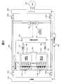
- FIG. 1 is a diagram showing a configuration of a battery system 100 according to the first embodiment of the present invention and its surroundings.
- Battery system 100 is connected to inverter 400 via relays 300a and 300b, and is connected to charger 420 via relays 300c and 300d.
- the battery system 100 includes an assembled battery 110, a single battery management unit 120, a current detection unit 130, a voltage detection unit 140, an assembled battery control unit 150, and a storage unit 180.
- the assembled battery 110 is composed of a plurality of unit cells 111.
- the unit cell management unit 120 monitors the state of the unit cell 111.
- the current detection unit 130 detects a current flowing through the battery system 100.
- the voltage detection unit 140 detects the total voltage of the assembled battery 110.
- the assembled battery control unit 150 detects the state of the assembled battery 110 and also manages the state.
- the assembled battery control unit 150 functions as a battery state detection device that detects the state of the assembled battery 110 in the battery system 100.
- the assembled battery control unit 150 includes a battery voltage and temperature of each unit cell 111 transmitted by the unit cell management unit 120, a current value flowing through the battery system 100 transmitted by the current detection unit 130, and an assembled battery transmitted by the voltage detection unit 140 A total voltage value of 110 is received.
- the assembled battery control unit 150 detects the state of the assembled battery 110 based on the received information. The result of the state detection by the assembled battery control unit 150 is transmitted to the single cell management unit 120 and the vehicle control unit 200.
- the assembled battery 110 is configured by electrically connecting a plurality of unit cells 111 capable of storing and releasing electrical energy (charging and discharging DC power) in series.
- the unit cells 111 constituting the assembled battery 110 are grouped into a predetermined number of units when performing state management / control.
- the grouped unit cells 111 are electrically connected in series to form unit cell groups 112a and 112b.
- the number of the single cells 111 constituting the single cell group 112 may be the same in all the single cell groups 112, or the number of the single cells 111 may be different for each single cell group 112.
- the single cell management unit 120 monitors the state of the single cells 111 constituting the assembled battery 110.
- the unit cell management unit 120 includes a unit cell control unit 121 provided for each unit cell group 112.
- cell control units 121 a and 121 b are provided corresponding to the cell groups 112 a and 112 b.
- the unit cell control unit 121 monitors and controls the state of the unit cells 111 constituting the unit cell group 112.
- unit cells 111 are electrically connected in series to form unit cell groups 112a and 112b, and the unit cell groups 112a and 112b are further electrically connected in series.
- an assembled battery 110 including a total of eight unit cells 111 was obtained.
- the assembled battery control unit 150 and the single cell management unit 120 transmit and receive signals via an insulating element 170 typified by a photocoupler and a signal communication unit 160.
- a communication means between the assembled battery control unit 150 and the unit cell control units 121a and 121b constituting the unit cell management unit 120 will be described.
- the cell control units 121a and 121b are connected in series according to the descending order of potentials of the cell groups 112a and 112b monitored by each.
- a signal transmitted from the assembled battery control unit 150 to the unit cell management unit 120 is input to the unit cell control unit 121 a via the insulating element 170 and the signal communication unit 160.
- the output of the unit cell control unit 121a is input to the unit cell control unit 121b via the signal communication unit 160, and the output of the lowest unit cell control unit 121b is supplied to the assembled battery control unit via the insulating element 170 and the signal communication unit 160.
- the insulating element 170 is not interposed between the unit cell control unit 121a and the unit cell control unit 121b, but signals can be transmitted and received through the insulating element 170.
- the storage unit 180 includes the assembled battery 110, the single battery 111, and the single battery group 112, the internal resistance characteristics, the capacity at full charge, the polarization voltage, the deterioration characteristics, the individual difference information, the SOC and the open circuit voltage (OCV: Open Circuit Voltage). Stores information such as correspondence relationships. Furthermore, characteristic information such as the single cell management unit 120, the single cell control unit 121, and the assembled battery control unit 150 can be stored in advance. Even when the operations of the battery system 100, the assembled battery control unit 150, and the like are stopped, various information stored in the storage unit 180 is retained.
- the assembled battery control unit 150 uses the information received from the single cell management unit 120, the current detection unit 130, the voltage detection unit 140, and the vehicle control unit 200, the SOC table 501 and the resistance characteristic table 901, which will be described later, and the like.
- the calculation for detecting the SOC, SOH, allowable charging / discharging current, electric power, etc. of the unit cell 111 is executed. And based on a calculation result, information is output to the cell management part 120 and the vehicle control part 200.
- the vehicle control unit 200 controls the inverter 400 connected to the battery system 100 via the relays 300a and 300b using the information transmitted by the assembled battery control unit 150. Moreover, the battery charger 420 connected to the battery system 100 via the relays 300c and 300d is controlled. During traveling of the vehicle, the battery system 100 is connected to the inverter 400 and drives the motor generator 410 using the energy stored in the assembled battery 110. At the time of charging, the battery system 100 is connected to a charger 420 and is charged by supplying power from a household power source or a charging stand.
- the charger 420 is used when charging the assembled battery 110 using an external power source represented by a home or a charging stand.
- the charger 420 is configured to control a charging voltage, a charging current, and the like based on a command from the vehicle control unit 200, but the control may be performed based on a command from the assembled battery control unit 150.
- the charger 420 may be installed inside the vehicle according to the configuration of the vehicle, the performance of the charger 420, the purpose of use, the installation conditions of the external power source, and the like, or may be installed outside the vehicle.
- the battery system 100 When the vehicle system on which the battery system 100 is mounted starts and runs, the battery system 100 is connected to the inverter 400 under the control of the vehicle control unit 200, and the motor uses the energy stored in the assembled battery 110.
- the generator 410 is driven.
- the assembled battery 110 is charged with the power generated by the motor generator 410.
- the battery system 100 and the charger 420 are connected based on information transmitted from the vehicle control unit 200, The battery 110 is charged until a predetermined condition is met.
- the energy stored in the assembled battery 110 by charging is used when the vehicle is driven next time, or is used to operate electrical components inside and outside the vehicle. Further, if necessary, it may be discharged to an external power source represented by a household power source.
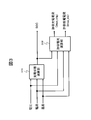
- FIG. 2 is a diagram showing a circuit configuration of the unit cell control unit 121.
- the cell control unit 121 includes a voltage detection circuit 122, a control circuit 123, a signal input / output circuit 124, and a temperature detection unit 125.
- the voltage detection circuit 122 measures the voltage between the terminals of each unit cell 111.
- the control circuit 123 receives measurement results from the voltage detection circuit 122 and the temperature detection unit 125, and transmits the measurement results to the assembled battery control unit 150 via the signal input / output circuit 124.
- it is determined that the circuit configuration that is generally implemented in the unit cell control unit 121 and that equalizes the voltage and SOC variation between the unit cells 111 generated due to self-discharge and variation in consumption current is known. The description is omitted.
- the temperature detection unit 125 included in the unit cell control unit 121 in FIG. 2 has a function of measuring the temperature of the unit cell group 112.
- the temperature detection unit 125 measures one temperature as the entire cell group 112 and treats the temperature as a temperature representative value of the cell 111 constituting the cell group 112.
- the temperature measured by the temperature detection unit 125 is used for various calculations for detecting the state of the cell 111, the cell group 112, or the assembled battery 110. Since FIG. 2 is based on this assumption, the single battery control unit 121 is provided with one temperature detection unit 125.
- a temperature detection unit 125 may be provided for each single cell 111 to measure the temperature for each single cell 111, and various calculations may be performed based on the temperature for each single cell 111. In this case, the number of temperature detection units 125 Therefore, the configuration of the unit cell control unit 121 becomes complicated.
- the temperature detection unit 125 is simply shown. Actually, a temperature sensor is installed on the temperature measurement target, and the installed temperature sensor outputs temperature information as a voltage. The measurement result is transmitted to the signal input / output circuit 124 via the control circuit 123, and the signal input / output circuit 124 outputs the measurement result to the outside of the unit cell control unit 121. A function for realizing this series of flows is implemented as a temperature detection unit 125 in the single cell control unit 121, and the voltage detection circuit 122 can be used for measuring temperature information (voltage).
- the assembled battery control unit 150 is realized by a microcomputer or the like, and can execute various processes and calculations as described below by executing various programs.
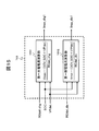
- FIG. 3 is a block diagram showing the processing contents performed by the assembled battery control unit 150 in the first embodiment of the present invention.
- the assembled battery control unit 150 functionally includes a charge state calculation unit 301 and an allowable current calculation unit 302.
- the charge state calculation unit 301 obtains the SOC using the voltage, current, and temperature.
- the allowable current calculation unit 302 calculates the allowable charge current (Imax_chg) and the allowable discharge current (Imax_dis) using the voltage, current, temperature, and the SOC determined by the charge state calculation unit 301.
- Imax_chg represents the allowable current of the assembled battery 110 during charging, that is, the maximum current that can be flowed when the assembled battery 110 is charged.
- Imax_dis represents an allowable current of the assembled battery 110 at the time of discharging, that is, a maximum current that can flow when the assembled battery 110 is discharged.
- the charging state calculation unit 301 includes a voltage obtained by dividing the inter-terminal voltage of the assembled battery 110 measured by the voltage detection unit 140 by the series number of the single cells 111, the current I measured by the current detection unit 130, and the temperature. Based on the temperature T measured by the detection unit 125, the SOC of the battery pack 110 is estimated. Below, the estimation process of the SOC based on a voltage is demonstrated as an example of the content of the process for SOC estimation which the charge condition calculating part 301 performs.
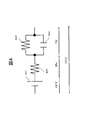
- FIG. 4 is a circuit diagram showing an equivalent circuit of the unit cell 111.
- the unit cell 111 includes a voltage source 401, a DC resistance 402, a polarization resistance 403, and a capacitance component 404.
- the polarization resistor 403 and the capacitance component 404 are connected in parallel, and the parallel connection pair, the voltage source 401, and the DC resistor 402 are connected in series.
- the OCV is used for the calculation of the SOC (charged state), but it is impossible to directly measure the OCV when the single cell 111 is charged / discharged. Therefore, the OCV is calculated by subtracting the IR drop and the polarization voltage Vp from the CCV according to the following formula (2) obtained by modifying the formula (1).
- OCV CCV-I x Ro-Vp (2)
- the resistance value Ro and the polarization voltage Vp of the DC resistor 402 can be determined by the characteristic information extracted from the unit cell 111.
- the characteristic information of the unit cell 111 is stored in advance in the storage unit 180 as a value obtained experimentally by charging and discharging the unit cell 111. If the characteristic information used when determining the resistance value Ro and the polarization voltage Vp of the DC resistor 402 is changed in accordance with the SOC, temperature, current, etc. of the unit cell 111, a highly accurate OCV can be obtained. . Further, the inter-terminal voltage CCV is obtained by dividing the measurement result of the voltage detection unit 140 by the serial number of the single cells 111, and the current I is obtained from the measurement result of the current detection unit 130.
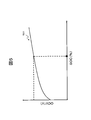
- FIG. 5 is a diagram illustrating an example of the SOC table 501 stored in the storage unit 180.
- the SOC table 501 is a data table describing a correspondence relationship between the OCV of the single battery 111 and the SOC of the single battery 111.
- the data format is arbitrary, but here it is shown in a graph format for convenience of explanation.
- the correspondence relationship between the OCV and the SOC can also be expressed by using a mathematical formula or the like. Other methods may be used as long as the method can convert from OCV to SOC or from SOC to OCV.
- the OCV is calculated by the equation (2), the SOC of the unit cell 111 can be estimated by using this SOC table 501.
- the charge state calculation unit 301 can also perform the SOC estimation of the unit cell 111 by the following equation (3).
- SOC0 represents the initial SOC value before charging / discharging of the unit cell 111
- the current I represents the measured value of the current detector 130.
- Qmax represents the capacity of the single battery 111 when fully charged, and this is stored in advance in the storage unit 180 as a value obtained experimentally by charging or discharging the single battery 111 or the assembled battery 110.
- SOCi SOC0 + 100 ⁇ ⁇ Idt / Qmax (3)
- the state-of-charge calculation unit 301 may perform SOC detection using either the formula (2) or the formula (3).
- the allowable current calculation unit 302 is a voltage obtained by dividing the inter-terminal voltage of the assembled battery 110 measured by the voltage detection unit 140 by the series number of the cells 111, the current measured by the current detection unit 130, and the temperature detection. Based on the temperature measured by the unit 125 and the SOC obtained by the state-of-charge computing unit 301, it has a function of obtaining the allowable current of the assembled battery 110 (unit cell 111).
- the allowable current is the maximum current that can be charged / discharged by the assembled battery 110 (unit cell 111), and is classified into an allowable charging current during charging and an allowable discharging current during discharging.
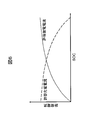
- FIG. 6 is a diagram showing the relationship between the allowable charging current and the allowable discharging current.
- the allowable discharge current is large and the allowable charge current is small.
- the SOC of the unit cell 111 is low, the allowable discharge current is small and the allowable charging current is large.
- the allowable current calculated by the allowable current calculation unit 302 is transmitted together with the SOC calculated by the charge state calculation unit 301 to a controller (vehicle control unit 200 in this embodiment) installed outside.
- the external controller that has received this charges / discharges the assembled battery 110 within the allowable current range.
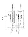
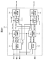
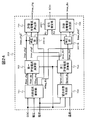
- FIG. 7 shows a block diagram of the allowable current calculation unit 302 in the first embodiment of the present invention.
- the allowable current calculation unit 302 includes an internal resistance detection unit 701, a battery state prediction unit 702, a first allowable current calculation unit 703, a second allowable current calculation unit 704, an allowable charge current determination unit 705, and an allowable discharge current.
- a determination unit 706 In the battery system 100 of FIG. 1, by executing a predetermined program in the assembled battery control unit 150 configured using a microcomputer or the like, the assembled battery control unit 150 can function as each unit illustrated in FIG. it can.
- the internal resistance detection unit 701 uses the SOC estimated by the charge state calculation unit 301 in FIG. 3, the voltage measured by the voltage detection unit 140, and the current measured by the current detection unit 130, and uses the assembled battery 110.
- the current internal resistance value of is calculated. Specifically, using the following formulas (4) and (5), the difference between the CCV during charge / discharge obtained as described above from the measured value of the voltage detection unit 140 and the OCV obtained from the SOC is calculated. By dividing by the current I measured by the current detector 130, the current internal resistance value of the assembled battery 110 can be calculated.
- OCV_SOC represents the value of OCV obtained from the SOC estimation result by the SOC table 501 shown in FIG.
- VDdet CCV-OCV_SOC (4)
- Rdet VDdet / I (5)
- FIG. 8 is an explanatory diagram of an internal resistance value calculation method by the internal resistance detection unit 701.
- diagrams 801 and 802 respectively show how CCV and OCV vary with time when the assembled battery 110 is discharged.
- the OCV gradually decreases with time, while the CCV rapidly decreases at the start of discharge and thereafter gradually decreases.
- the CCV increases rapidly, and then coincides with the OCV after a predetermined time has elapsed.
- the internal resistance detection unit 701 calculates the difference VDdet between the OCV and CCV during discharge shown in FIG. 8 from the equation (4), and divides this VDdet by the current I according to the equation (5), thereby obtaining the internal resistance value Rdet. Calculate.
- the calculation of the internal resistance value by the internal resistance detection unit 701 is executed only when the current measurement value by the current detection unit 130 is equal to or greater than a predetermined threshold value.
- the internal resistance detection unit 701 substitutes the value of Rdet obtained by Equations (4) and (5) into Rdet_chg representing the internal resistance value during charging.
- a charge flag Rflag_chg for indicating whether or not the internal resistance value during charging of the battery 110 has been detected is set to “1”.
- Rdet_dis representing the internal resistance value at the time of discharging to indicate whether or not the internal resistance value at the time of discharging the assembled battery 110 has been detected.
- the discharge flag Rflag_dis is set to “0”.
- the internal resistance detection unit 701 substitutes the value of Rdet obtained in Equations (4) and (5) for Rdet_dis and sets Rflag_dis to '1'. To do.
- a predetermined invalid value or a predetermined internal resistance value is substituted for Rdet_chg, and Rflag_chg is set to ‘0’.
- the internal resistance detection unit 701 When a current less than the threshold is detected, the internal resistance detection unit 701 cannot calculate both the internal resistance value Rdet_chg during charging and the internal resistance value Rdet_dis during discharging. In this case, the internal resistance detection unit 701 substitutes a predetermined invalid value or a predetermined internal resistance value into Rdet_chg and Rdet_dis, respectively, and sets both Rflag_chg and Rflag_dis to ‘0’.
- the voltage used by the internal resistance detection unit 701 is a voltage obtained by dividing the inter-terminal voltage of the assembled battery 110 measured by the voltage detection unit 140 by the number of cells 111 in series. Therefore, the internal resistance value obtained by the above calculation is an average internal resistance value of each unit cell 111 constituting the assembled battery 110. Thereafter, the allowable current is obtained using this internal resistance value, but the voltage to be handled needs to be a value corresponding to the unit cell 111.
- the battery state prediction unit 702 has a function of predicting the state of the assembled battery 110 without using the voltage (CCV) measured by the voltage detection unit 140.
- the battery state prediction unit 702 outputs Rpred_chg that represents the predicted internal resistance value during charging of the current assembled battery 110 and Rpred_dis that represents the predicted internal resistance value during discharge as battery characteristic information that represents the prediction result of the battery state. To do.
- Rpred_chg and Rpred_dis can be estimated from the SOC estimated by the charge state calculation unit 301 in FIG. 3 and the temperature received from the temperature detection unit 125 in FIG. This is because a resistance characteristic is extracted by performing a charge / discharge test on the assembled battery 110 or the single battery 111 in advance, and the result is stored in the storage unit 180 as a resistance characteristic table according to the SOC, temperature, and the like. realizable.
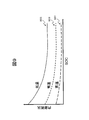
- FIG. 9 is a diagram illustrating an example of the resistance characteristic tables 901, 902, and 903 stored in the storage unit 180. These are data tables describing the correspondence between the internal resistance of the assembled battery 110 and the SOC of the assembled battery 110.
- the resistance characteristic table 901 shows the characteristics at high temperature
- the resistance characteristic table 902 shows the characteristics at normal temperature
- a resistance characteristic table 903 represents characteristics at low temperatures.
- the data format is arbitrary, but here it is shown in a graph format for convenience of explanation. In the present embodiment, three types of data tables corresponding to the temperature are used. However, the correspondence relationship between the internal resistance, the SOC, and the temperature can also be expressed by using mathematical expressions.
- the battery state prediction unit 702 estimates Rpred_chg and Rpred_dis from the SOC estimated by the charge state calculation unit 301 in FIG. 3 and the temperature received from the temperature detection unit 125 in FIG. 2 using the resistance characteristic table. Note that this internal resistance prediction method is an example, and the internal resistance can also be predicted by the following method. That is, the estimated voltage drop value (VDpred) on the charging side when the battery is charged and the discharging side when the battery is discharged is obtained by the equation (6).
- I is the current charge / discharge current
- ROpred is the resistance characteristic table value of the DC resistor 402 having a value according to the SOC, temperature, etc.
- VPpred is the polarization generated by connecting the polarization resistor 403 and the capacitance component 404 in parallel. It is the result of predicting the voltage by calculation. The prediction of the polarization voltage is based on the characteristics of the polarization resistance 403 and the capacitance component 404 (or the time constant obtained by multiplying the polarization resistance 403 and the capacitance component 404 by conducting a charge / discharge test on the assembled battery 110 or the single cell 111 in advance.
- the internal resistance detection unit 701 detects the internal resistance value of the assembled battery 110 based on the voltage of the assembled battery 110 detected by the voltage detection unit 140. In order to detect the internal resistance value, it is necessary to use the voltage detection result of the assembled battery 110. For this reason, the internal resistance detection unit 701 has a restriction that both the internal resistance value Rdet_chg during charging and the internal resistance value Rdet_dis during discharging cannot be calculated simultaneously. That is, as described above, Rdet_chg can be calculated only during charging when the charging current flowing through the assembled battery 110 exceeds the threshold value. Rdet_dis can be calculated only when the discharge current from the assembled battery 110 exceeds a threshold value.
- the battery state prediction unit 702 estimates the internal resistance value of the assembled battery 110 using the characteristic information of the assembled battery 110 stored in advance without using the voltage of the assembled battery 110 detected by the voltage detection unit 140. I do. Therefore, it is possible to always predict Rpred_chg representing the internal resistance value during charging and Rpred_dis representing the internal resistance value during discharging, regardless of the charge / discharge state of the assembled battery 110. However, when the characteristics of the assembled battery 110 extracted in advance do not match the characteristics of the current assembled battery 110, the output from the battery state prediction unit 702 includes an error corresponding to the difference.
- the first allowable current calculation unit 703 obtains an allowable current based on the voltage of the assembled battery 110 detected by the voltage detection unit 140. Specifically, the internal resistance value Rdet_chg on the charge side and the internal resistance value Rdet_dis on the discharge side detected by the internal resistance detection unit 701 based on the voltage measurement result by the voltage detection unit 140, and the charge state calculation unit 301 in FIG.
- the allowable charging is performed using OCV_SOC, which is the OCV value obtained from the SOC estimated by the above, and the upper limit voltage Vmax and the lower limit voltage Vmin determined from the characteristics of the assembled battery 110.
- Imax_chg1 (Vmax ⁇ OCV_SOC) / Rdet_chg (7)
- Imax_dis1 (Vmin ⁇ OCV_SOC) / Rdet_dis (8)
- FIG. 10 is a block diagram of calculation processing performed by the first allowable current calculation unit 703.
- the first allowable current calculation unit 703 includes a first charging current calculation unit 1001 corresponding to the calculation of Equation (7) and a first discharge current calculation unit 1002 corresponding to the calculation of Equation (8).
- the first charging current calculation unit 1001 uses the internal resistance value Rdet_chg on the charging side input from the internal resistance detection unit 701 and the SOC input from the charge state calculation unit 301, and allows the allowable charging according to Expression (7).
- the current Imax_chg1 is calculated and output.
- the first discharge current calculation unit 1002 uses the discharge-side internal resistance value Rdet_dis input from the internal resistance detection unit 701 and the SOC input from the charge state calculation unit 301 to calculate the allowable discharge according to equation (8).
- the current Imax_dis1 is calculated and output.
- the internal resistance detection unit 701 can calculate Rdet_chg only during charging and can calculate Rdet_dis only during discharging. Therefore, there is a restriction that the first allowable current calculation unit 703 can also calculate Imax_chg1 only during charging and can calculate Imax_dis1 only during discharging.
- the first allowable current calculation unit 703 calculates the allowable charging current Imax_chg1 and the allowable discharge current Imax_dis1 using the voltage detection result by the voltage detection unit 140.
- the second allowable current calculation unit 704 obtains the allowable current of the assembled battery 110 without using the voltage of the assembled battery 110 detected by the voltage detection unit 140.
- OCV_SOC OCV value obtained from the SOC estimated by the computing unit 301
- Vmax and the lower limit voltage Vmin determined from the characteristics of the assembled battery 110
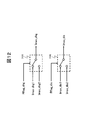
- FIG. 11 is a block diagram of calculation processing performed by the second allowable current calculation unit 704.
- the second allowable current calculation unit 704 includes a second charging current calculation unit 1101 corresponding to the calculation of Expression (9) and a second discharge current calculation unit 1102 corresponding to the calculation of Expression (10).
- the second charging current calculation unit 1101 uses the internal resistance value Rpred_chg on the charging side input from the battery state prediction unit 702 and the SOC input from the charging state calculation unit 301, and allows the allowable charging according to Expression (9).
- the current Imax_chg2 is calculated and output.
- the second discharge current calculation unit 1102 uses the discharge-side internal resistance value Rpred_dis input from the battery state prediction unit 702 and the SOC input from the charge state calculation unit 301, and allows the allowable discharge according to the equation (10).
- the current Imax_dis2 is calculated and output.
- the battery state prediction unit 702 can always calculate Rpred_chg and Rpred_dis regardless of the charge / discharge state of the assembled battery 110. Therefore, the second allowable current calculation unit 704 can always calculate the allowable charge current Imax_chg2 and the allowable discharge current Imax_dis2 regardless of the charge / discharge state of the assembled battery 110.
- the output from the battery state prediction unit 702 includes an error corresponding to the difference. There is a possibility. For this reason, the Imax_chg2 and Imax_dis2 output from the second allowable current calculation unit 704 may include an allowable current error corresponding to the above error.
- the first allowable current calculation unit 703 is limited in the calculation condition that the allowable current can be calculated only during charging / discharging of the assembled battery 110, while the second allowable current calculation unit 704 There are no restrictions on the calculation conditions. However, in the allowable current calculated by the second allowable current calculation unit 704, an error occurs when there is a difference between the battery characteristics extracted in advance and the current battery characteristics. Therefore, in the present embodiment, when the allowable current calculation unit 302 satisfies the condition that the first allowable current calculation unit 703 can calculate the allowable current, that is, when the charge / discharge current of the assembled battery 110 is equal to or greater than a predetermined threshold, The output from one allowable current calculation unit 703 is determined as the final allowable current of the assembled battery 110.
- the allowable current calculation unit 302 includes an allowable charging current determination unit 705 and an allowable discharge current determination unit 706.
- the allowable charge current determination unit 705 determines the final allowable charge based on the allowable charge current Imax_chg1 calculated by the first allowable current calculation unit 703 and the allowable charge current Imax_chg2 calculated by the second allowable current calculation unit 704.
- the current Imax_chg is determined and output. Specifically, based on the value of the charging flag Rflag_chg output from the internal resistance detection unit 701, either the allowable charging current Imax_chg1 or the allowable charging current Imax_chg2 is selected and output as the allowable charging current Imax_chg.
- the allowable discharge current determination unit 706 determines the final allowable discharge based on the allowable discharge current Imax_dis1 calculated by the first allowable current calculation unit 703 and the allowable discharge current Imax_dis2 calculated by the second allowable current calculation unit 704.
- the current Imax_dis is determined and output. Specifically, based on the value of the discharge flag Rflag_dis output from the internal resistance detector 701, either the allowable discharge current Imax_dis1 or the allowable discharge current Imax_dis2 is selected and output as the allowable discharge current Imax_dis.
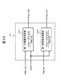
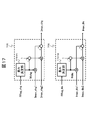
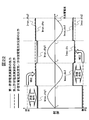
- FIG. 12 is a diagram illustrating an example of a block diagram of arithmetic processing performed by the allowable charging current determination unit 705 and the allowable discharge current determination unit 706 in the first embodiment of the present invention.
- the allowable charge current determination unit 705 realized using a switch selects the allowable charge current Imax_chg1 output from the first allowable current calculation unit 703, and the charge flag When Rflag_chg is “0”, the allowable charging current Imax_chg2 output from the second allowable current calculator 704 is selected.
- the allowable discharge current determination unit 706 realized using a switch selects the allowable discharge current Imax_dis1 output from the first allowable current calculation unit 703 when the discharge flag Rflag_dis is “1”, and discharge flag Rflag_dis. Is “0”, the allowable discharge current Imax_dis2 output from the second allowable current calculation unit 704 is selected.
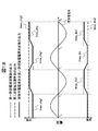
- FIG. 13 is a diagram illustrating a state of the allowable current finally output from the allowable current calculation unit 302 in the first embodiment of the present invention.
- the charging / discharging current is changed into a sine wave having a fixed period as shown in the figure, and the case where the current value is positive is defined as charging, and the case where the current value is negative is defined as discharging.
- Rflag_chg is immediately set to “1” when the current direction is the charging direction
- Rflag_dis is immediately set to “1” when the current direction is the discharging direction.
- the internal resistance detection unit 701 can obtain the internal resistance value Rdet_chg on the charging side, and using this, the first allowable current calculation unit 703 calculates the allowable charging current Imax_chg1. Can be sought.
- the internal resistance value Rpred_chg on the charging side predicted by the battery state prediction unit 702 is estimated from the battery characteristics stored in advance, it is calculated by the second allowable current calculation unit 704 using this.
- the allowable charging current Imax_chg2 has a larger error than Imax_chg1.
- the allowable charging current determination unit 705 determines Imax_chg1 from the first allowable current calculation unit 703 as the final allowable charging current, and sets the allowable charging current Imax_chg. Output.
- the first allowable current calculator 703 cannot determine the allowable discharge current Imax_dis1.
- the second allowable current calculation unit 704 can obtain the allowable discharge current Imax_dis2 using the internal resistance value Rpred_dis on the discharge side predicted by the battery state prediction unit 702. Therefore, the allowable discharge current determination unit 706 determines Imax_dis2 from the second allowable current calculation unit 704 as the final allowable discharge current when the direction of the charge / discharge current is the charging direction, and sets the allowable discharge current Imax_dis as the allowable discharge current Imax_dis. Output.
- the internal resistance detection unit 701 can obtain the internal resistance value Rdet_dis on the discharge side, and the first allowable current calculation unit 703 uses this to determine the allowable discharge current Imax_dis1. Can be sought.
- the internal resistance value Rpred_dis on the discharge side predicted by the battery state prediction unit 702 is estimated from the battery characteristics stored in advance, it is calculated by the second allowable current calculation unit 704 using this.
- the allowable discharge current Imax_dis2 has a larger error than Imax_dis1.
- the allowable discharge current determination unit 706 determines Imax_dis1 from the first allowable current calculation unit 703 as the final allowable discharge current when the direction of the charge / discharge current becomes the discharge direction, and sets the allowable discharge current Imax_dis as the allowable discharge current Imax_dis. Output.
- the first allowable current calculation unit 703 cannot obtain the allowable charging current Imax_chg1.
- the second allowable current calculation unit 704 can obtain the allowable charging current Imax_chg2 by using the charging-side internal resistance value Rpred_chg predicted by the battery state prediction unit 702. Therefore, when the charge / discharge current direction is the discharge direction, allowable charge current determination unit 705 determines Imax_chg2 from second allowable current calculation unit 704 as the final allowable charge current, and sets the allowable charge current Imax_chg. Output.
- the allowable charging current determination unit 705 determines the allowable charging current Imax_chg2 obtained by the second allowable current calculation unit 704 as a final combination during discharging before the charging of the assembled battery 110 is started.
- the allowable charging current Imax_chg of the battery 110 is determined and output.
- the allowable charging current Imax_chg is determined by the first allowable current calculating unit 703 from the allowable charging current Imax_chg2 determined by the second allowable current calculating unit 704. Switching to an allowable charging current Imax_chg1 with a small error.
- the allowable discharge current determination unit 706 calculates the allowable discharge current Imax_dis2 obtained by the second allowable current calculation unit 704 during the charging before the discharge of the assembled battery 110 is started.
- the allowable discharge current Imax_dis is determined and output.
- the allowable discharge current Imax_dis is obtained from the allowable discharge current Imax_dis2 obtained by the second allowable current calculation unit 704, and obtained from the first allowable current calculation unit 703. Switching to the allowable discharge current Imax_dis1 with a small error.
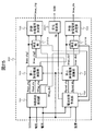
- FIG. 14 shows a block diagram of an allowable current calculation unit 302 different from FIG. 7 outputs the detected internal resistance values Rdet_chg and Rdet_dis, and Rflag_chg and Rflag_dis indicating whether the internal resistance value has been detected.
- the internal resistance detection unit 701 in FIG. 14 outputs the detected DC resistance values ROdet_chg and ROdet_dis, the detected polarization voltage VPdet, and Rflag_chg and Rflag_dis indicating whether the battery information has been detected.
- 7 output the predicted internal resistance values Rpred_chg and Rpred_dis, but in FIG. 14, the predicted DC resistance values ROpred_chg and ROpred_dis and the predicted polarization voltage VPpred are output.
- the internal resistance detection unit 701 detects the current DC resistance value of the assembled battery 110 using the voltage measured by the voltage detection unit 140 and the current measured by the current detection unit 130. Specifically, the direct current resistance value is obtained using the following equation (11). In equation (11), t is time, V (t) is the voltage measured by the voltage detector 140 at time t, and I (t) is the current value measured by the current detector 130 at time t. Represents.
- ROdet (V (t) -V (t-1)) / (I (t) -I (t-1)) (11)
- the value of the DC resistance obtained by Expression (11) may become unstable depending on the measurement performance of the voltage detection unit 140 and the current detection unit 130 and the condition in which Expression (11) is executed. Therefore, if necessary, the ROdet obtained by executing the expression (11) a plurality of times may be averaged and used in subsequent calculations.
- ROdet_chg a charge flag for indicating whether or not the DC resistance value during charging of the assembled battery 110 has been detected is set to ' Set to 1 '.
- a predetermined invalid value or a predetermined DC resistance value is substituted into ROdet_dis representing the DC resistance value at the time of discharging to indicate whether or not the DC resistance value at the time of discharging the assembled battery 110 has been detected.
- the discharge flag Rflag_dis is set to “0”.
- the direct current resistance of the assembled battery 110 does not change greatly in a short time, when the direct current resistance value ROdet_dis at the time of discharge cannot be calculated, the direct current resistance value ROdet_dis at the time of discharge can be used. .
- Rflag_dis is set to ‘0’.
- the internal resistance detection unit 701 substitutes the obtained ROdet value into ROdet_dis, and Rflag_dis Is set to '1'.
- a predetermined invalid value or a predetermined DC resistance value is substituted for ROdet_chg, and Rflag_chg is set to ‘0’.
- the DC resistance value ROdet_chg at the time of charging cannot be calculated, the DC resistance value ROdet_chg at the time of charging previously obtained Can also be used.
- Rflag_chg is set to “0”.
- the DC resistance is When it is difficult to detect, the internal resistance detection unit 701 cannot calculate both the DC resistance value ROdet_chg during charging and the DC resistance value ROdet_dis during discharging. In this case, the internal resistance detection unit 701 substitutes a predetermined invalid value or a predetermined DC resistance value into ROdet_chg and ROdet_dis, respectively, and sets both Rflag_chg and Rflag_dis to ‘0’.
- the DC resistance value ROdet_chg at the time of charging and the DC resistance value ROdet_dis at the time of discharging cannot be calculated
- the DC resistance value ROdet_chg at the time of charging and the DC resistance value ROdet_dis at the time of discharging are utilized and charged for a predetermined time or more.
- Rflag_chg and Rflag_dis are set to “0”.
- the internal resistance detection unit 701 detects the DC resistance value of the assembled battery 110.
- the internal resistance detector 701 here detects the polarization voltage of the battery pack 110 (VPdet). Equation (12) shows a method for detecting the polarization voltage.
- VPdet CCV-OCV_SOC- I ⁇ ROdet (12)
- CCV is the voltage value during charging / discharging measured by the voltage detection unit 140
- OCV_SOC is the OCV value obtained from the SOC estimation result by the SOC table 501 shown in FIG. 5, and I is measured by the current detection unit 130.
- the current value ROdet is a DC resistance detected on the charging side or discharging side of the assembled battery 110 detected by the internal resistance detection unit 701.
- the detection result of VPdet is output together with the DC resistance values ROdet_chg and ROdet_dis, and Rflag_chg and Rflag_dis indicating whether or not the battery state has been detected, and is used for calculation of allowable current described later.
- the battery state prediction unit 702 in FIG. 14 will be described.
- the internal resistance detection unit 701 can detect a battery state such as a DC resistance value only when a predetermined condition is satisfied.
- the battery state predicting section 702 described here is the battery state predicting section 702 corresponding to the difference.
- the output from the battery includes an error, the battery state can always be output to the outside.
- the battery state prediction unit 702 has a function of predicting the state of the assembled battery 110 without using the voltage (CCV) measured by the voltage detection unit 140.
- the battery state prediction unit 702 predicts the battery state by using ROpred_chg representing the predicted DC resistance value during charging of the current assembled battery 110, ROpred_dis representing the predicted DC resistance value during discharging, and VPpred representing the predicted polarization voltage value. Output as battery characteristic information representing the result.
- ROpred_chg and ROpred_dis can be estimated from the SOC estimated by the charge state calculation unit 301 in FIG. 3 and the temperature received from the temperature detection unit 125 in FIG. This is because a resistance characteristic is extracted by performing a charge / discharge test on the assembled battery 110 or the single battery 111 in advance, and the result is stored in the storage unit 180 as a resistance characteristic table according to the SOC, temperature, and the like. realizable. Further, VPpred can predict the polarization voltage generated by connecting the polarization resistance 403 and the capacitance component 404 in parallel as described in the description of the expression (6).
- FIG. 15 is a block diagram of calculation processing performed by the first allowable current calculation unit 703.
- the influence of the polarization voltage is included in Rdet_chg and Rdet_dis to calculate the allowable current.
- the allowable current is obtained without converting the polarization voltage into a resistance value.
- Imax_chg1 ⁇ Vmax ⁇ (OCV_SOC + VPdet) ⁇ / ROdet_chg (13)
- Imax_dis1 ⁇ Vmin ⁇ (OCV_SOC + VPdet) ⁇ / ROdet_dis (14)
- the second allowable current calculation unit 704 obtains the allowable current of the assembled battery 110 by receiving the output from the battery state prediction unit 702 and VPdet that is the output from the internal resistance detection unit 701. Specifically, the predicted DC resistance predicted value ROpred_chg on the charge side, the predicted DC resistance value ROpred_dis on the discharge side, and OCV_SOC that is the OCV value obtained from the SOC estimated by the charge state calculation unit 301 in FIG.
- FIG. 16 is a block diagram of calculation processing performed by the second allowable current calculation unit 704.
- the reason why VPdet is used as an input in addition to VPpred is that the polarization voltage is a common parameter that can be detected on the charge side and used on the discharge side, and can be detected on the discharge side and used on the charge side.
- the VPdet detected by the internal resistance detection unit 701 can be used also by the second allowable current calculation unit 704, and before the VPdet is detected by the internal resistance detection unit 701, VPpred is used, and when VPdet is detected, priority is given to accuracy.
- the process of adopting VPdet can be realized.
- the second allowable current calculation unit 704 handles only the output from the battery state prediction unit 702, that is, the processing content in which the polarization voltage is only the predicted value VPpred. It is also possible to adopt.
- the polarization voltage predicted value VPpred or the polarization voltage VPdet detected in equation (12) is substituted.
- the polarization voltage predicted value VPpred is substituted and used for VP, and when an effective polarization voltage VPdet is detected by the internal resistance detector 701, VPdet is substituted for VP and used, and Imax_chg2 And Imax_dis2 are obtained.
- the allowable charging current determination unit 705 and the allowable discharge current determination unit 706 in FIG. 14 have the same functions as those in FIG. That is, the allowable charging current determination unit 705 selects either the allowable charging current Imax_chg1 or the allowable charging current Imax_chg2 based on the value of the charging flag Rflag_chg output from the internal resistance detection unit 701, and outputs it as the allowable charging current Imax_chg. To do.
- the allowable discharge current determination unit 706 selects either the allowable discharge current Imax_dis1 or the allowable discharge current Imax_dis2 based on the value of the discharge flag Rflag_dis output from the internal resistance detection unit 701, and outputs it as the allowable discharge current Imax_dis.
- the allowable current can be calculated with high accuracy as described with reference to FIG.
- the allowable current calculation unit 302 includes a first allowable current calculation unit 703, a second allowable current calculation unit 704, an allowable charging current determination unit 705, and an allowable discharge current determination unit 706. Is provided.
- the first allowable current calculation unit 703 obtains the allowable charging current Imax_chg1 and the allowable discharging current Imax_dis1 as the allowable current of the assembled battery 110 based on the voltage of the assembled battery 110 detected by the voltage detecting unit 140.
- the second allowable current calculation unit 704 obtains the allowable charging current Imax_chg2 and the allowable discharging current Imax_dis2 as the allowable current of the assembled battery 110 without using the voltage of the assembled battery 110.
- the allowable charging current determining unit 705 determines the allowable charging current Imax_chg of the assembled battery 110 according to the state of the assembled battery 110 based on at least one of the allowable charging current Imax_chg1 and the allowable charging current Imax_chg2, and the allowable discharging current determining unit 706 determines the allowable discharge current Imax_dis of the assembled battery 110 according to the state of the assembled battery 110 based on at least one of the allowable discharge current Imax_dis1 and the allowable discharge current Imax_dis2. Since it did in this way, the allowable current of the assembled battery 110 can be detected with high accuracy.
- the allowable charging current determination unit 705 determines the allowable charging current Imax_chg1 as the allowable charging current Imax_chg of the assembled battery 110 when the assembled battery 110 is in a state where the allowable charging current Imax_chg1 is obtained, and the allowable charging current When the assembled battery 110 is in a state where Imax_chg1 cannot be obtained, the allowable charging current Imax_chg2 is determined as the allowable charging current Imax_chg of the assembled battery 110.
- the charging current of the assembled battery 110 is equal to or greater than a predetermined threshold, it is determined that the assembled battery 110 is in a state where the allowable charging current Imax_chg1 is obtained, and the allowable charging current Imax_chg1 is determined as the allowable charging of the assembled battery 110.
- the allowable charging current Imax_chg is determined as the allowable charging of the assembled battery 110.
- the allowable charging current Imax_chg2 is The current is determined as Imax_chg.
- the allowable discharge current determination unit 706 determines the allowable discharge current Imax_dis1 as the allowable discharge current Imax_dis of the assembled battery 110, and allows the allowable discharge current Imax_dis1. Is determined as the allowable discharge current Imax_dis of the assembled battery 110. Specifically, when the discharge current of the assembled battery 110 is equal to or greater than a predetermined threshold, it is determined that the assembled battery 110 is in a state where the allowable discharge current Imax_dis1 is obtained, and the allowable discharge current Imax_dis1 is set to the allowable discharge current of the assembled battery 110.
- the allowable discharge current Imax_dis is determined and the discharge current of the assembled battery 110 is less than the threshold, it is determined that the assembled battery 110 is in a state where the allowable discharge current Imax_dis1 cannot be obtained, and the allowable discharge current Imax_dis2 is determined as the allowable discharge of the assembled battery 110. Determined as current Imax_dis. Since it did in this way, according to the state of the assembled battery 110, an optimal allowable current can be determined.
- the allowable charging current determination unit 705 determines the allowable charging current Imax_chg2 as the allowable charging current Imax_chg of the assembled battery 110 before the charging of the assembled battery 110 is started, and charging of the assembled battery 110 is started. After that, the allowable charging current Imax_chg of the assembled battery 110 is switched from the allowable charging current Imax_chg2 to the allowable charging current Imax_chg1. Further, the allowable discharge current determining unit 706 determines the allowable discharge current Imax_dis2 as the allowable discharge current Imax_dis of the assembled battery 110 before the discharge of the assembled battery 110 is started, and after the discharge of the assembled battery 110 is started.
- the allowable charging current determining unit 705 and the allowable discharging current determining unit 706 determine the allowable charging current Imax_chg1 as the allowable charging current Imax_chg of the assembled battery 110 for the charging side.
- the allowable discharge current Imax_dis2 is determined as the allowable discharge current Imax_dis of the battery pack 110.
- the allowable charging current Imax_chg2 is determined as the allowable charging current Imax_chg of the assembled battery 110 for the charging side
- the allowable discharging current Imax_dis1 of the assembled battery 110 is determined for the discharging side. Determined as Imax_dis.
- the allowable charging current Imax_chg and the allowable discharging current Imax_dis of the assembled battery 110 are set to the allowable charging current Imax_chg1 or the allowable discharging current Imax_dis1 for each of the charging side and the discharging side. Switching between charging current Imax_chg2 or allowable discharge current Imax_dis2. Since it did in this way, according to switching of charging / discharging of the assembled battery 110, a suitable allowable current can be selected.
- FIG. 17 is a diagram illustrating an example of a block diagram of arithmetic processing performed by the allowable charging current determination unit 705 and the allowable discharge current determination unit 706 in the second embodiment of the present invention.
- the allowable charge current determination unit 705 and the allowable discharge current determination unit 706 are provided with weight determination units 1701A and 1701B, respectively.
- the weight determination units 1701A and 1701B have a function of outputting weight coefficients Wchg and Wdis that continuously change between 0 and 1 when the charge flag Rflag_chg or the discharge flag Rflag_dis changes.
- the weight determination unit 1701A changes the weight coefficient Wchg from 0 to 1 with a predetermined gradient, and conversely, the charge flag Rflag_chg changes to “1”.
- the weight determination unit 1701A changes the weight coefficient Wchg from 1 to 0 with a predetermined gradient.
- the discharge flag Rflag_dis changes from “0” to “1”
- the weight determination unit 1701B changes the weight coefficient Wdis from 0 to 1 with a predetermined gradient, and conversely, the discharge flag Rflag_dis changes from “1” to “1”.
- the weight determination unit 1701B changes the weight coefficient Wdis from 1 to 0 with a predetermined gradient.
- the allowable charging current determination unit 705 and the allowable discharge current determination unit 706 use the weighting factors Wchg and Wdis output as described above to calculate the first allowable current calculation unit according to the following equations (17) and (18).
- the allowable charge current Imax_chg1 and allowable discharge current Imax_dis1 from 703 and the allowable charge current Imax_chg2 and allowable discharge current Imax_dis2 from the second allowable current calculation unit 704 are respectively weighted, and the final allowable current of the assembled battery 110 is calculated. calculate.
- Imax_chg Wchg x Imax_chg1 + (1-Wchg) x Imax_chg2 (17)
- Imax_dis Wdis ⁇ Imax_dis1 + (1 ⁇ Wdis) ⁇ Imax_dis2 (18)
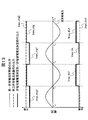
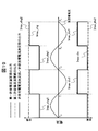
- FIG. 18 is a diagram illustrating a state of the allowable current finally output from the allowable current calculation unit 302 in the second embodiment of the present invention.
- the charge / discharge current was changed to a sine wave with a constant period as shown in the figure, and the case where the current value was positive was defined as charging, and the case where the current value was negative was defined as discharging.
- Rflag_chg is immediately set to “1” when the current direction is the charging direction
- Rflag_dis is immediately set to “1” when the current direction is the discharging direction.
- the allowable charging current determining unit 705 and the allowable discharging current determining unit 706 set the weighting coefficient Wchg to 1 and the weighting coefficient Wdis to 0, respectively. Thereby, on the charge side, the weight for the allowable charge current Imax_chg1 from the first allowable current calculation unit 703 is relatively increased, and for the discharge side, the weight for the allowable discharge current Imax_dis2 from the second allowable current calculation unit 704. Is relatively large.
- the allowable charge current determination unit 705 gradually changes the weighting coefficient Wchg from 1 to 0.
- the weighting for the allowable charging current Imax_chg1 is gradually decreased, and the weighting for the allowable charging current Imax_chg2 is gradually increased.
- the allowable charging current Imax_chg output from the allowable charging current determination unit 705 gradually changes from Imax_chg1 to Imax_chg2, as shown in the figure.
- the allowable discharge current determination unit 706 gradually changes the weighting coefficient Wdis from 0 to 1.
- the weighting for the allowable discharge current Imax_dis1 is gradually increased, and the weighting for the allowable discharge current Imax_dis2 is gradually decreased.
- the allowable discharge current Imax_dis output from the allowable discharge current determination unit 706 gradually changes from Imax_dis2 to Imax_dis1, as shown in the figure.
- the allowable charging current determining unit 705 and the allowable discharging current determining unit 706 set the weighting coefficient Wchg to 0 and the weighting coefficient Wdis to 1, respectively.
- the weighting for the allowable charging current Imax_chg2 from the second allowable current calculating unit 704 is relatively increased, and for the discharging side, the weighting for the allowable discharging current Imax_dis1 from the first allowable current calculating unit 703. Is relatively large.
- the allowable charge current determination unit 705 gradually changes the weighting coefficient Wchg from 0 to 1.
- the weighting for the allowable charging current Imax_chg1 is gradually increased, and the weighting for the allowable charging current Imax_chg2 is gradually decreased.
- the allowable charging current Imax_chg output from the allowable charging current determination unit 705 gradually changes from Imax_chg2 to Imax_chg1, as shown in the figure.
- the allowable discharge current determining unit 706 gradually changes the weighting coefficient Wdis from 1 to 0.
- the weighting for the allowable discharge current Imax_dis1 is gradually decreased, and the weighting for the allowable discharge current Imax_dis2 is gradually increased.
- the allowable discharge current Imax_dis output from the allowable discharge current determination unit 706 gradually changes from Imax_dis1 to Imax_dis2, as shown in the figure.
- the first allowable current calculation unit 703 uses these values.
- the allowable charging current Imax_chg1 and the allowable discharging current Imax_dis1 are calculated, there is a possibility that a large error is included in the calculation result.
- the maximum value, the minimum value, the average value, and the like of the internal resistance value assumed according to the characteristics of the assembled battery 110 can be considered. The larger the difference is, the larger the error included in the calculation result of the first allowable current calculation unit 703 is.
- the last calculated internal resistance value is held in the internal resistance detection unit 701, and when the internal resistance detection unit 701 cannot execute the calculation of the internal resistance value, the held internal resistance value is output. It is preferable to do. In this way, it is possible to prevent the allowable charging current Imax_chg and the allowable discharging current Imax_dis output from the allowable charging current determining unit 705 and the allowable discharging current determining unit 706 from changing abruptly when charging / discharging is switched. it can.
- the allowable charging current determining unit 705 determines a weighting coefficient Wchg for the allowable charging current Imax_chg1 and the allowable charging current Imax_chg2, and weights the allowable charging current Imax_chg1 and the allowable charging current Imax_chg2 based on the weighting coefficient Wchg, respectively. By doing so, the allowable charging current Imax_chg of the assembled battery 110 is determined.
- the allowable discharge current determination unit 706 determines a weighting factor Wdis for the allowable discharge current Imax_dis1 and the allowable discharge current Imax_dis2, and weights and sums the allowable discharge current Imax_dis1 and the allowable discharge current Imax_dis2 based on the weighting factor Wdis. Thus, the allowable discharge current Imax_dis of the assembled battery 110 is determined. Since it did in this way, an appropriate allowable current can be calculated
- the allowable charging current determination unit 705 and the allowable discharge current determination unit 706 change the weighting factors Wchg and Wdis, respectively, while the assembled battery 110 is being charged or discharged.
- the allowable charging current determination unit 705 relatively increases the weighting for the allowable charging current Imax_chg2 before the charging of the assembled battery 110 is started, and after the charging of the assembled battery 110 is started, The weighting for the charging current Imax_chg1 is gradually increased, and the weighting for the allowable charging current Imax_chg2 is gradually decreased.
- the allowable discharge current determination unit 706 relatively increases the weighting for the allowable discharge current Imax_dis2 before the discharge of the assembled battery 110 is started, and after the discharge of the assembled battery 110 is started, the allowable discharge is determined.
- the weight for the current Imax_dis1 is gradually increased, and the weight for the allowable discharge current Imax_dis2 is gradually decreased. Since it did in this way, an allowable electric current can be changed smoothly at the time of the charge / discharge switching of the assembled battery 110.
- the block diagram of the arithmetic processing performed by the allowable charging current determination unit 705 and the allowable discharge current determination unit 706 is the same as that in FIG. That is, the allowable charging current determination unit 705 and the allowable discharge current determination unit 706 are provided with weight determination units 1701A and 1701B, respectively.
- the weight determination units 1701A and 1701B receive the charge flag Rflag_chg and the discharge flag Rflag_dis, respectively, and the weight coefficient Wchg that continuously changes between 0 and 1 based on these values. , Wdis is described as output.
- the first allowable current calculation unit 703 and the second allowable current calculation unit 704 calculate the error of the respective allowable currents, and the weight determination units 1701A and 1701B use the weighting factor Wchg. , Wdis will be described as an example.
- the first allowable current calculation unit 703 adds an allowable charging current error ⁇ Imax_chg1 and an allowable discharging current error ⁇ Imax_dis1 that represent these errors in addition to the calculation of the allowable charging current Imax_chg1 and the allowable discharging current Imax_dis1 described above. Perform the operation.
- second allowable current calculation unit 704 further calculates allowable charge current error ⁇ Imax_chg2 and allowable discharge current error ⁇ Imax_dis2 representing these errors. .
- the allowable charging current error ⁇ Imax_chg1 obtained by the first allowable current calculating unit 703 and the allowable charging current error ⁇ Imax_chg2 obtained by the second allowable current calculating unit 704 are input to the weight determining unit 1701A by the allowable charging current determining unit 705. Is done.
- the allowable discharge current error ⁇ Imax_dis1 obtained by the first allowable current calculation unit 703 and the allowable discharge current error ⁇ Imax_dis2 obtained by the second allowable current calculation unit 704 are input to the weight determination unit 1701B by the allowable discharge current determination unit 706. Is done.
- the allowable charge current error ⁇ Imax_chg1 and the allowable discharge current error ⁇ Imax_dis1, the allowable charge current error ⁇ Imax_chg2 and the allowable discharge current error ⁇ Imax_dis2 are the measurement errors of the current detection unit 130, the voltage detection unit 140, and the temperature detection unit 125, and It is possible to calculate by grasping in advance the difference between the equivalent circuit and the actual battery voltage and using these as inputs.
- the weight determination units 1701A and 1701B determine the weighting factors Wchg and Wdis by the following equations (19) and (20), respectively, using the input allowable current errors.
- Wchg ⁇ Imax_chg2 2 / ( ⁇ Imax_chg1 2 + ⁇ Imax_chg2 2 ) (19)
- Wdis ⁇ Imax_dis2 2 / ( ⁇ Imax_dis1 2 + ⁇ Imax_dis2 2 ) (20)
- the allowable charging current determining unit 705 and the allowable discharging current determining unit 706 can calculate the allowable current of the final assembled battery 110 according to the above equations (17) and (18), respectively. Can be calculated.
- the processing may be simplified by determining the weight coefficients Wchg and Wdis according to only the error included in the calculation result of the first allowable current calculation unit 703, respectively.
- the allowable charge current determination unit 705 and the allowable discharge current determination unit 706 respectively calculate the weighting factors Wchg and Wdis based on the allowable charge current error ⁇ Imax_chg1 and the allowable discharge current error ⁇ Imax_dis1 obtained by the first allowable current calculation unit 703. decide.
- the first allowable current calculation unit 703 uses these values.
- the allowable charging current Imax_chg1 and the allowable discharging current Imax_dis1 are calculated, there is a possibility that a large error is included in the calculation result. Therefore, in such a case, it is preferable that the values of the allowable charging current error ⁇ Imax_chg1 and the allowable discharging current error ⁇ Imax_dis1 output from the first allowable current calculation unit 703 are the maximum values within an assumed range.
- the weighting for the allowable charging current Imax_chg1 and the allowable discharging current Imax_dis1 including a large error is minimized, while the weighting for the allowable charging current Imax_chg2 and the allowable discharging current Imax_dis2 is maximized to obtain an appropriate allowable current. be able to.
- the first allowable current calculation unit 703 performs the allowable charging current error ⁇ Imax_chg1 that represents the error of the allowable charging current Imax_chg1 and the allowable discharge current that represents the error of the allowable discharge current Imax_dis1.
- An error ⁇ Imax_dis1 is obtained.
- the second allowable current calculation unit 704 obtains an allowable charging current error ⁇ Imax_chg2 that represents an error in the allowable charging current Imax_chg2, and an allowable discharge current error ⁇ Imax_dis2 that represents an error in the allowable discharge current Imax_dis2.
- the allowable charging current determination unit 705 and the allowable discharge current determination unit 706 determine the weighting factors Wchg and Wdis based on at least one of these errors. Since it did in this way, a suitable allowable current can be calculated
- the battery state prediction unit 702 predicts the state of the assembled battery 110 according to the battery characteristics obtained by performing a charge / discharge test in advance, if the battery characteristic changes as described above, an error occurs in the battery state prediction result. . Therefore, this error is also included in the allowable charge current Imax_chg2 and the allowable discharge current Imax_dis2 calculated by the second allowable current calculation unit 704 using the prediction result of the battery state prediction unit 702.
- FIG. 19 shows the allowable current finally output from the allowable current calculation unit 302 when the calculation accuracy of the second allowable current calculation unit 704 is reduced without performing the correction in the fourth embodiment of the present invention. It is a figure which shows a mode.
- the allowable charge current Imax_chg1 output from the first allowable current calculation unit 703, as shown in FIG.
- the difference between the allowable discharge current Imax_dis1 and the allowable charge current Imax_chg2 and the allowable discharge current Imax_dis2 output from the second allowable current calculation unit 704 is increased. Therefore, when charging / discharging of the assembled battery 110 is switched, a large fluctuation occurs in the allowable current output from the allowable current calculation unit 302.
- FIG. 20 is an example of a block diagram of the allowable current calculation unit 302 in the fourth embodiment of the present invention.
- correction units 2001A and 2001B are further added in FIG.
- the correcting unit 2001A compares the allowable charging current Imax_chg1 from the first allowable current calculating unit 703 with the allowable charging current Imax_chg2 from the second allowable current calculating unit 704, and determines the allowable charging current Imax_chg2 based on the comparison result. to correct.
- the correction unit 2001B compares the allowable discharge current Imax_dis1 from the first allowable current calculation unit 703 with the allowable discharge current Imax_dis2 from the second allowable current calculation unit 704, and determines the allowable discharge current Imax_dis2 based on the comparison result. to correct.
- the correction unit 2001A obtains a difference between the allowable charging current Imax_chg1 and the allowable charging current Imax_chg2, and corrects the allowable charging current Imax_chg2 using a correction coefficient determined based on the difference.
- the ratio between the allowable charging current Imax_chg1 and the allowable charging current Imax_chg2 is obtained, and the allowable charging current Imax_chg2 is corrected using a correction coefficient determined based on this ratio. Then, the correction result is output as the corrected allowable charging current Imax_chg2 '.
- the correction unit 2001B calculates a difference between the allowable discharge current Imax_dis1 and the allowable discharge current Imax_dis2, and corrects the allowable discharge current Imax_dis2 using a correction coefficient determined based on the difference.
- a ratio between the allowable discharge current Imax_dis1 and the allowable discharge current Imax_dis2 is obtained, and the allowable discharge current Imax_dis2 is corrected using a correction coefficient determined based on this ratio.
- the correction result is output as a corrected allowable discharge current Imax_dis2 '.
- it is good also as a correction coefficient common by the charge side and the discharge side by determining a correction coefficient from the average value of these differences and ratios.
- the correction may be performed when the difference or ratio is out of the predetermined range without performing the correction.
- a correction coefficient according to the charging / discharging time of the assembled battery 110 and the polarization voltage such as VPpred that can be output from the battery state prediction unit 702.
- the correction units 2001A and 2001B hold in advance a plurality of correction coefficients according to the difference or ratio between the allowable charging current Imax_chg1 and the allowable charging current Imax_chg2, and the difference or ratio between the allowable discharging current Imax_dis1 and the allowable discharging current Imax_dis2.
- the allowable charging current Imax_chg2 and the allowable discharging current Imax_dis2 can be corrected using the correction coefficient selected from these.
- FIG. 21 is another example of a block diagram of the allowable current calculation unit 302 in the fourth embodiment of the present invention.
- correction units 2101A and 2101B are further added in FIG.
- the correction unit 2101A compares the allowable charging current Imax_chg1 from the first allowable current calculation unit 703 with the allowable charging current Imax_chg2 from the second allowable current calculation unit 704, and based on the comparison result, the battery state prediction unit 702 Among the battery characteristic information output as the prediction result of the battery state, the second allowable current calculation unit 704 corrects what is used for obtaining the allowable charging current Imax_chg2.
- the correction unit 2101B compares the allowable discharge current Imax_dis1 from the first allowable current calculation unit 703 with the allowable discharge current Imax_dis2 from the second allowable current calculation unit 704, and based on the comparison result, the battery state prediction unit 702 Among the battery characteristic information output as the prediction result of the battery state is corrected by the second allowable current calculation unit 704 used to obtain the allowable discharge current Imax_dis2.
- the correction unit 2101A obtains the difference or ratio between the allowable charging current Imax_chg1 and the allowable charging current Imax_chg2, and in the direction in which these are eliminated, the internal resistance prediction value Rpred_chg during charging output from the battery state prediction unit 702 Correct.
- the correction unit 2101B obtains the difference or ratio between the allowable discharge current Imax_dis1 and the allowable discharge current Imax_dis2, and corrects the predicted internal resistance value Rpred_dis at the time of discharge output from the battery state prediction unit 702 in a direction in which these are eliminated. To do. In addition, you may perform a correction
- the correction may be performed when the difference or ratio is out of the predetermined range without performing the correction.
- the correction coefficient may be determined according to the charging / discharging time of the battery pack 110 and the polarization voltage such as VPpred that can be output by the battery state prediction unit 702. You may make it correct
- the correction units 2101A and 2101B hold in advance a plurality of correction coefficients corresponding to the difference or ratio between the allowable charge current Imax_chg1 and the allowable charge current Imax_chg2, and the difference or ratio between the allowable discharge current Imax_dis1 and the allowable discharge current Imax_dis2. Then, the internal resistance prediction values Rpred_chg, Rpred_dis, etc. can be corrected using the correction coefficient selected according to the difference or ratio.
- the outputs of the first allowable current calculation unit 703 and the second allowable current calculation unit 704 are compared, and based on the comparison result, the first The allowable current error included in the output of the second allowable current calculation unit 704 can be improved.
- FIG. 22 is a diagram illustrating a state of the allowable current finally output from the allowable current calculation unit 302 in the fourth embodiment of the present invention.
- Imax_chg1 output from the first allowable current calculation unit 703 and Imax_chg2 output from the second allowable current calculation unit 704 within the period from time T0 to time T1. Yes.
- Imax_chg2 output from the second allowable current calculation unit 704 is corrected by the above correction processing.
- Imax_dis2 output from the second allowable current calculation unit 704 is corrected by the above correction processing.
- the allowable current calculation unit 302 includes a first allowable current calculation unit 703, a second allowable current calculation unit 704, an allowable charging current determination unit 705, and an allowable discharge current determination unit 706. , Correction units 2001A and 2001B, or correction units 2101A and 2101B.
- the first allowable current calculation unit 703 obtains the allowable charging current Imax_chg1 and the allowable discharging current Imax_dis1 as the allowable current of the assembled battery 110 based on the voltage of the assembled battery 110 detected by the voltage detecting unit 140.
- the second allowable current calculation unit 704 obtains the allowable charging current Imax_chg2 and the allowable discharging current Imax_dis2 as the allowable current of the assembled battery 110 without using the voltage of the assembled battery 110.
- Correction units 2001A and 2101A compare allowable charging current Imax_chg1 and allowable charging current Imax_chg2, and perform predetermined correction processing based on the comparison result.
- Correction units 2001B and 2101B compare allowable discharge current Imax_dis1 and allowable discharge current Imax_dis2, and perform predetermined correction processing based on the comparison result. Since it did in this way, the allowable current of the assembled battery 110 can be detected with high accuracy in consideration of the influence of the increase in internal resistance according to the deterioration state of the assembled battery 110.
- the correction units 2001A and 2001B perform correction processing by correcting the calculation results of the allowable charge current Imax_chg2 and the allowable discharge current Imax_dis2 by the second allowable current calculation unit 704, respectively. Further, the correction units 2101A and 2101B correct the internal resistance prediction values Rpred_chg and Rpred_dis, which are characteristic information of the assembled battery 110 used by the second allowable current calculation unit 704 to obtain the allowable charging current Imax_chg2 and the allowable discharging current Imax_dis2, respectively. Perform correction processing. Since it did in this way, according to the raise of the internal resistance of the assembled battery 110, an appropriate correction
- the correction units 2001A, 2001B, 2101A, and 2101B have a plurality of correction coefficients according to the difference or ratio between the allowable charge current Imax_chg1 and the allowable charge current Imax_chg2, or the difference or ratio between the allowable discharge current Imax_dis1 and the allowable discharge current Imax_dis2.
- Each correction process is performed using a correction coefficient selected from among the plurality of correction coefficients. Since it did in this way, a correction
- the correction units 2001A, 2001B, 2101A, and 2101B can determine the correction coefficient used for each correction process according to the charging / discharging time of the battery pack 110 or the polarization voltage such as VPpred. In this way, more appropriate correction processing can be performed in consideration of the deterioration state of the assembled battery 110.
- the correction units 2001A and 2101A compare the allowable charging current Imax_chg1 and the allowable charging current Imax_chg2 when the assembled battery 110 is charged, and perform respective correction processes based on the comparison result. Further, the correction units 2001B and 2101B compare the allowable discharge current Imax_dis1 and the allowable discharge current Imax_dis2 when the assembled battery 110 is discharged, and perform respective correction processes based on the comparison result. Since it did in this way, according to the charging / discharging state of the assembled battery 110, the allowable electric current made into the object of a correction process can be switched appropriately.
- FIG. 23 is a block diagram showing the processing contents performed by the assembled battery control unit 150 in the fifth embodiment of the present invention.
- the assembled battery control unit 150 of this embodiment monitors the output of the allowable current calculation unit 302 and compares the assembled battery 110 with the block diagram shown in FIG. 3 in the first embodiment. It further includes a deterioration estimation unit 2301 for estimating the deterioration state.
- the battery pack 110 undergoes characteristic changes such as an increase in internal resistance and a decrease in full charge capacity when deterioration progresses as charging and discharging are repeated.
- the deterioration estimation unit 2301 estimates the deterioration of the assembled battery 110 by monitoring the degree of decrease in the allowable current.
- SOH the SOH of the battery pack 110 when the calculation result of the degree of decrease in the allowable current using the following formula (21) is defined as SOH is obtained.
- Imax_new represents the allowable current of the assembled battery 110 when new
- Imax_det represents the current allowable current of the assembled battery 110 (during deterioration).
- SOH Imax_det / Imax_new (21)
- the allowable charging current determining unit 705 determines the allowable charging current Imax_chg. Further, based on the allowable discharge current Imax_dis1 obtained by the first allowable current calculation unit 703 and the allowable discharge current Imax_dis2 obtained by the second allowable current calculation unit 704, the allowable discharge current determination unit 706 allows the allowable discharge current Imax_dis. Is determined.
- the degradation estimation unit 2301 pays attention to one or both of the allowable charging current Imax_chg and the allowable discharging current Imax_dis, and stores the output from the allowable current calculating unit 302 at the time of starting use of the assembled battery 110 as Imax_new.
- the current SOH of the assembled battery 110 can be estimated by Expression (21) using the current output from the allowable current calculation unit 302 as Imax_det.
- the allowable charge current Imax_chg and the allowable discharge current Imax_dis may be averaged to obtain Imax_det and Imax_new.
- the degradation estimation unit 2301 may directly estimate the SOH of the assembled battery 110 using the output from the first allowable current calculation unit 703 or the output from the second allowable current calculation unit 704 directly. That is, when paying attention to the output of the first allowable current calculation unit 703, one or both of the allowable charging current Imax_chg1 and the allowable discharging current Imax_dis1 at the time when the use of the assembled battery 110 is started is defined as Imax_new, and the current allowable charging current. With one or both of Imax_chg1 and allowable discharge current Imax_dis1 as Imax_det, the current SOH of the assembled battery 110 can be estimated by Expression (21).
- the allowable charging current Imax_chg2 and the allowable discharging current Imax_dis2 at the start of use of the assembled battery 110 is set to Imax_new, and the current allowable charging current is set.
- Imax_chg2 and allowable discharge current Imax_dis2 as Imax_det
- the current SOH of the assembled battery 110 can be estimated from Equation (21).
- the SOH of the assembled battery 110 estimated by the deterioration estimation unit 2301 as described above is received by the vehicle control unit 200.
- the vehicle control unit 200 determines that the assembled battery 110 has a life when the received SOH value falls below a predetermined threshold value. Note that the life estimation of the assembled battery 110 may be performed by the deterioration estimation unit 2301. Moreover, it is also possible to determine that the lifetime is reached when the allowable current value obtained by the calculation is less than the threshold value without using the parameter SOH.
- the deterioration estimation unit 2301 includes at least the calculation result of the allowable current by the first allowable current calculation unit 703 and the calculation result of the allowable current by the second allowable current calculation unit 704.
- One is monitored and the deterioration state of the assembled battery 110 is estimated. Since it did in this way, in the battery system 100, the progress of deterioration of the assembled battery 110 can be determined accurately.
- the deterioration estimation unit 2301 may determine whether the assembled battery 110 is at the end of its life based on the estimation result of the deterioration state of the assembled battery 110. If it does in this way, in battery system 100, lifetime judgment of assembled battery 110 can be performed exactly.
- FIG. 24 is a block diagram of the allowable current calculation unit 302 in the sixth embodiment of the present invention.
- a deterioration estimation unit 2401 is further added in FIG.
- the deterioration estimation unit 2401 monitors the coefficient Kc indicating the correction amount or correction rate of the allowable current by the correction unit 2001A and the coefficient Kd indicating the correction amount or correction rate of the allowable current by the correction unit 2001B, thereby monitoring the assembled battery 110.
- Estimate the SOH Since the allowable current decreases when the assembled battery 110 deteriorates, the correction unit 2001A and the correction unit 2001B correct the calculation result of the allowable current to match this. This is because the coefficients Kc and Kd indicating the correction amount or correction rate of the allowable current for this purpose can be used as parameters for grasping the degree of deterioration of the assembled battery 110 instead of SOH.
- the deterioration estimation unit 2401 monitors the result of the correction processing by the correction units 2001A and 2001B, and estimates the deterioration state of the assembled battery 110. Since it did in this way, in the battery system 100, the progress of deterioration of the assembled battery 110 can be determined accurately.
- the deterioration estimation unit 2401 may determine whether the assembled battery 110 is at the end of its life based on the estimation result of the deterioration state of the assembled battery 110. If it does in this way, in battery system 100, lifetime judgment of assembled battery 110 can be performed exactly.
- FIG. 25 is a block diagram of the allowable current calculation unit 302 in the seventh embodiment of the present invention.
- a deterioration estimation unit 2501 is further added in FIG.
- the deterioration estimation unit 2501 estimates the SOH of the assembled battery 110 by monitoring the correction result Rt for the output from the battery state prediction unit 702 by the correction units 2101A and 2101B.
- the internal resistance prediction values Rpred_chg and Rpred_dis corrected by the correction units 2101A and 2101B are acquired as correction results Rt
- the SOH of the current assembled battery 110 is estimated by using the following equation (22). Can do.
- R_new represents the internal resistance of the assembled battery 110 when new
- R_det represents the current internal resistance of the assembled battery 110 (during deterioration).
- SOH R_det / R_new (22)
- the correcting unit 2101A includes the allowable charging current Imax_chg1 obtained by the first allowable current calculating unit 703 and the allowable charging current Imax_chg2 obtained by the second allowable current calculating unit 704. Based on the above, the internal resistance prediction value Rpred_chg during charging output from the battery state prediction unit 702 is corrected. Further, the correction unit 2101B is configured to output the battery state prediction unit 702 from the allowable discharge current Imax_dis1 obtained by the first allowable current calculation unit 703 and the allowable discharge current Imax_dis2 obtained by the second allowable current calculation unit 704. The predicted internal resistance value Rpred_dis during discharge is corrected.
- the deterioration estimation unit 2501 pays attention to one or both of the correction results of the predicted internal resistance values Rpred_chg and Rpred_dis, and stores the output from the battery state prediction unit 702 as R_new when the use of the assembled battery 110 is started.
- the SOH of the current assembled battery 110 can be estimated by the expression (22), where R_det is the output from the current battery state prediction unit 702.
- R_det and R_new may be obtained by averaging the predicted internal resistance value Rpred_chg during charging and the predicted internal resistance value Rpred_dis during discharging.
- the deterioration estimation unit 2501 monitors the result of correction processing by the correction units 2101A and 2101B, and estimates the deterioration state of the assembled battery 110. Since it did in this way, in the battery system 100, the progress of deterioration of the assembled battery 110 can be determined accurately.
- the deterioration estimation unit 2501 may determine whether the assembled battery 110 is at the end of its life based on the estimation result of the deterioration state of the assembled battery 110. If it does in this way, in battery system 100, lifetime judgment of assembled battery 110 can be performed exactly.
- each of the above-described configurations, functions, processing units, etc. can be realized as hardware by designing all or a part thereof, for example, with an integrated circuit, or the processor executes a program for realizing each function. By doing so, it can also be realized as software. Information such as programs and tables for realizing each function can be stored in a storage device such as a memory or a hard disk, or a storage medium such as an IC card or a DVD. In addition, a program for causing the assembled battery control unit 150 of the battery system 100 according to each of the above-described embodiments to execute processing as described in each of the embodiments through an electric communication line such as the storage medium or the Internet is provided. You can also
- FIG. 26 is a diagram illustrating a state in which a program is provided to the assembled battery control unit 150.
- the personal computer 10 is connected to the assembled battery control unit 150, and supplies the assembled battery control unit 150 with a program provided from the server device 11 via the communication line 12 or a program read from the CD-ROM 13.
- the program can also be supplied from the server device 11 to the assembled battery control unit 150 via the communication line 12 without using the personal computer 10.
- the communication line 12 is a communication line such as the Internet or personal computer communication, a dedicated communication line, a mobile phone line network, or the like.
- the server 11 transmits the program to the personal computer 10 and the assembled battery control unit 150 via the communication line 12. That is, the program is converted into a data signal on a carrier wave and transmitted via the communication line 12.
- a program executable in the assembled battery control unit 150 can be provided as a computer-readable program product in various forms such as a recording medium and a carrier wave.
- battery system 110 assembled battery 111: single battery 112: single battery group 120: single battery management unit 121: single battery control unit 122: voltage detection circuit 123: control circuit 124: signal input Output circuit, 125: temperature detection unit, 130: current detection unit, 140: voltage detection unit, 150: assembled battery control unit, 160: signal communication means, 170: insulating element, 180: storage unit, 200: vehicle control unit, 300a to 300d: relay, 301: charge state calculation unit, 302: allowable current calculation unit, 400: inverter, 410: motor generator, 420: charger, 701: internal resistance detection unit, 702: battery state prediction unit, 703: First allowable current calculation unit, 704: second allowable current calculation unit, 705: allowable charge current determination unit, 706: allowable discharge current determination unit, 2001A, 2001B, 2 01A, 2101B: correction unit, 2301,2401,2501: deterioration estimating unit
Landscapes
- Engineering & Computer Science (AREA)
- Physics & Mathematics (AREA)
- General Physics & Mathematics (AREA)
- Power Engineering (AREA)
- Transportation (AREA)
- Life Sciences & Earth Sciences (AREA)
- Sustainable Development (AREA)
- Sustainable Energy (AREA)
- Mechanical Engineering (AREA)
- General Chemical & Material Sciences (AREA)
- Electrochemistry (AREA)
- Chemical Kinetics & Catalysis (AREA)
- Chemical & Material Sciences (AREA)
- Manufacturing & Machinery (AREA)
- Secondary Cells (AREA)
- Charge And Discharge Circuits For Batteries Or The Like (AREA)
- Tests Of Electric Status Of Batteries (AREA)
Abstract
L'invention concerne un dispositif de détection d'état de batterie qui détecte l'état d'une batterie et comprend : une première unité de calcul de courant admissible qui identifie un premier courant admissible pour la batterie, en fonction de la tension de batterie détectée par une unité de détection de tension ; une deuxième unité de calcul de courant admissible qui identifie un deuxième courant admissible pour la batterie, sans utiliser la tension de la batterie ; et une unité de correction qui compare le premier courant admissible et le deuxième courant admissible et effectue un traitement de correction prédéterminé en fonction des résultats de comparaison.
Priority Applications (3)
| Application Number | Priority Date | Filing Date | Title |
|---|---|---|---|
| US15/317,025 US10725111B2 (en) | 2014-07-17 | 2015-06-12 | Battery state detection device, secondary battery system, program product, and battery state detection method |
| CN201580039065.XA CN106662621B (zh) | 2014-07-17 | 2015-06-12 | 电池状态检测装置、二次电池系统、程序产品和电池状态检测方法 |
| EP15822305.7A EP3171187B1 (fr) | 2014-07-17 | 2015-06-12 | Dispositif de détection d'état de batterie, système de batterie rechargeable, produit programme, et procédé de détection d'état de batterie |
Applications Claiming Priority (2)
| Application Number | Priority Date | Filing Date | Title |
|---|---|---|---|
| JP2014-146750 | 2014-07-17 | ||
| JP2014146750A JP6324248B2 (ja) | 2014-07-17 | 2014-07-17 | 電池状態検知装置、二次電池システム、電池状態検知プログラム、電池状態検知方法 |
Publications (1)
| Publication Number | Publication Date |
|---|---|
| WO2016009757A1 true WO2016009757A1 (fr) | 2016-01-21 |
Family
ID=55078258
Family Applications (1)
| Application Number | Title | Priority Date | Filing Date |
|---|---|---|---|
| PCT/JP2015/067007 WO2016009757A1 (fr) | 2014-07-17 | 2015-06-12 | Dispositif de détection d'état de batterie, système de batterie rechargeable, produit programme, et procédé de détection d'état de batterie |
Country Status (5)
| Country | Link |
|---|---|
| US (1) | US10725111B2 (fr) |
| EP (1) | EP3171187B1 (fr) |
| JP (1) | JP6324248B2 (fr) |
| CN (1) | CN106662621B (fr) |
| WO (1) | WO2016009757A1 (fr) |
Cited By (2)
| Publication number | Priority date | Publication date | Assignee | Title |
|---|---|---|---|---|
| WO2018047258A1 (fr) * | 2016-09-07 | 2018-03-15 | 日立化成株式会社 | Procédé et dispositif de simulation |
| CN110281812A (zh) * | 2019-06-27 | 2019-09-27 | 一汽解放汽车有限公司 | 一种基于工况识别的续航里程估算系统 |
Families Citing this family (13)
| Publication number | Priority date | Publication date | Assignee | Title |
|---|---|---|---|---|
| JP2015155859A (ja) * | 2014-02-21 | 2015-08-27 | ソニー株式会社 | 電池残量推定装置、電池パック、蓄電装置、電動車両および電池残量推定方法 |
| KR102554151B1 (ko) * | 2017-10-24 | 2023-07-12 | 삼성전자주식회사 | 배터리 충전 방법 및 장치 |
| CN108407626B (zh) * | 2018-01-12 | 2020-12-22 | 山东艾诺仪器有限公司 | 人工智能电动车电池电量检测修正及阶段充电电路 |
| JP2019132696A (ja) * | 2018-01-31 | 2019-08-08 | トヨタ自動車株式会社 | 全固体電池の制御装置 |
| KR102373449B1 (ko) * | 2018-02-01 | 2022-03-10 | 주식회사 엘지에너지솔루션 | 배터리의 전력 한계 결정 방법 및 배터리 관리 시스템 |
| CN112470020B (zh) | 2018-08-28 | 2024-05-07 | 本田技研工业株式会社 | 诊断装置、诊断方法、诊断系统及存储介质 |
| CN112277724A (zh) * | 2019-07-25 | 2021-01-29 | 北汽福田汽车股份有限公司 | 电池系统的管理方法、管理装置、存储介质和车辆 |
| US11522440B2 (en) * | 2020-07-29 | 2022-12-06 | Cirrus Logic, Inc. | Use of shared feedback among two or more reactive schemes |
| CN116250110A (zh) * | 2021-02-09 | 2023-06-09 | 宁德时代新能源科技股份有限公司 | 电池充电方法、控制器、电池管理系统、电池和用电装置 |
| FR3122536B1 (fr) * | 2021-04-29 | 2023-06-30 | Psa Automobiles Sa | Contrôle d'un ensemble électrique pour une batterie électrique d'un véhicule automobile |
| FR3123518A1 (fr) * | 2021-05-26 | 2022-12-02 | Psa Automobiles Sa | Procede de gestion energetique d’une batterie de servitude au lithium-ion |
| EP4152553B1 (fr) * | 2021-07-29 | 2024-04-24 | Contemporary Amperex Technology Co., Limited | Appareil de charge et de décharge, procédé de charge de batterie et système de charge et de décharge |
| KR102508333B1 (ko) * | 2022-11-04 | 2023-03-10 | 씨에스테크놀로지 주식회사 | 전기자동차의 충전 시간 단축을 위한 충전전류 제어 방법 |
Citations (3)
| Publication number | Priority date | Publication date | Assignee | Title |
|---|---|---|---|---|
| JP2006197727A (ja) * | 2005-01-13 | 2006-07-27 | Sanyo Electric Co Ltd | 電池の制限電流制御方法 |
| JP4722857B2 (ja) * | 2003-11-20 | 2011-07-13 | エルジー・ケム・リミテッド | 進歩セルモデル予測技術を用いたバッテリパックの電力容量の計算方法 |
| WO2013094057A1 (fr) * | 2011-12-22 | 2013-06-27 | 日立ビークルエナジー株式会社 | Dispositif de commande de batterie et système de batterie |
Family Cites Families (15)
| Publication number | Priority date | Publication date | Assignee | Title |
|---|---|---|---|---|
| JP4097183B2 (ja) * | 2001-12-27 | 2008-06-11 | パナソニックEvエナジー株式会社 | 二次電池の残存容量推定方法および装置、並びに電池パックシステム |
| JP2006129588A (ja) * | 2004-10-28 | 2006-05-18 | Sanyo Electric Co Ltd | 二次電池の電力制御方法及び電源装置 |
| JP4488426B2 (ja) * | 2005-06-08 | 2010-06-23 | 富士重工業株式会社 | 蓄電デバイスの制御装置 |
| JP5004557B2 (ja) * | 2006-11-09 | 2012-08-22 | 三洋電機株式会社 | 電池の劣化度の検出方法 |
| JP4987581B2 (ja) * | 2007-06-15 | 2012-07-25 | 日立ビークルエナジー株式会社 | 電池制御装置 |
| JP5040733B2 (ja) | 2008-03-05 | 2012-10-03 | 日産自動車株式会社 | 電池の充放電可能電力推定方法 |
| JP4856209B2 (ja) * | 2009-03-30 | 2012-01-18 | 株式会社東芝 | 電池性能測定装置、電池制御システム及び車両 |
| JP5646214B2 (ja) * | 2010-05-27 | 2014-12-24 | 三洋電機株式会社 | 電源装置 |
| DE102010062856A1 (de) | 2010-12-10 | 2012-06-21 | Sb Limotive Company Ltd. | Verfahren zur Ermittlung von Betriebsparametern einer Batterie, Batteriemanagementsystem und Batterie |
| CN102074757B (zh) | 2010-12-24 | 2013-02-13 | 惠州市亿能电子有限公司 | 一种锂离子电池荷电状态的估算方法 |
| WO2012091077A1 (fr) * | 2010-12-28 | 2012-07-05 | 三洋電機株式会社 | Procédé de détection de niveau de dégradation de batterie |
| US9641011B2 (en) * | 2011-06-10 | 2017-05-02 | Hitachi Automotive Systems, Ltd. | Battery control device adapting the battery current limit by decreasing the stored current limit by comparing it with the measured battery current |
| CN103635822B (zh) | 2011-08-30 | 2016-02-10 | 三洋电机株式会社 | 电池系统、电动车辆、移动体、电力储存装置以及电源装置 |
| US9557388B2 (en) | 2012-05-24 | 2017-01-31 | Hitachi Automotive Systems, Ltd. | Battery control device |
| JPWO2014083856A1 (ja) * | 2012-11-30 | 2017-01-05 | 三洋電機株式会社 | 電池管理装置、電源装置およびsoc推定方法 |
-
2014
- 2014-07-17 JP JP2014146750A patent/JP6324248B2/ja active Active
-
2015
- 2015-06-12 US US15/317,025 patent/US10725111B2/en active Active
- 2015-06-12 CN CN201580039065.XA patent/CN106662621B/zh active Active
- 2015-06-12 WO PCT/JP2015/067007 patent/WO2016009757A1/fr active Application Filing
- 2015-06-12 EP EP15822305.7A patent/EP3171187B1/fr active Active
Patent Citations (3)
| Publication number | Priority date | Publication date | Assignee | Title |
|---|---|---|---|---|
| JP4722857B2 (ja) * | 2003-11-20 | 2011-07-13 | エルジー・ケム・リミテッド | 進歩セルモデル予測技術を用いたバッテリパックの電力容量の計算方法 |
| JP2006197727A (ja) * | 2005-01-13 | 2006-07-27 | Sanyo Electric Co Ltd | 電池の制限電流制御方法 |
| WO2013094057A1 (fr) * | 2011-12-22 | 2013-06-27 | 日立ビークルエナジー株式会社 | Dispositif de commande de batterie et système de batterie |
Non-Patent Citations (1)
| Title |
|---|
| See also references of EP3171187A4 * |
Cited By (3)
| Publication number | Priority date | Publication date | Assignee | Title |
|---|---|---|---|---|
| WO2018047258A1 (fr) * | 2016-09-07 | 2018-03-15 | 日立化成株式会社 | Procédé et dispositif de simulation |
| JPWO2018047258A1 (ja) * | 2016-09-07 | 2019-06-24 | 日立化成株式会社 | シミュレーション方法およびシミュレーション装置 |
| CN110281812A (zh) * | 2019-06-27 | 2019-09-27 | 一汽解放汽车有限公司 | 一种基于工况识别的续航里程估算系统 |
Also Published As
| Publication number | Publication date |
|---|---|
| CN106662621B (zh) | 2020-09-15 |
| JP2016023968A (ja) | 2016-02-08 |
| US20170131360A1 (en) | 2017-05-11 |
| CN106662621A (zh) | 2017-05-10 |
| EP3171187A1 (fr) | 2017-05-24 |
| EP3171187A4 (fr) | 2018-04-04 |
| JP6324248B2 (ja) | 2018-05-16 |
| US10725111B2 (en) | 2020-07-28 |
| EP3171187B1 (fr) | 2019-08-28 |
Similar Documents
| Publication | Publication Date | Title |
|---|---|---|
| JP6324248B2 (ja) | 電池状態検知装置、二次電池システム、電池状態検知プログラム、電池状態検知方法 | |
| JP6316690B2 (ja) | 電池状態検知装置、二次電池システム、電池状態検知プログラム、電池状態検知方法 | |
| US11124072B2 (en) | Battery control device and electric motor vehicle system | |
| JP6033155B2 (ja) | 電池制御装置 | |
| US10209317B2 (en) | Battery control device for calculating battery deterioration based on internal resistance increase rate | |
| JP6101714B2 (ja) | 電池制御装置、電池システム | |
| CN103608994A (zh) | 电池控制装置、电池系统 | |
| JP7067549B2 (ja) | 蓄電素子管理装置及び蓄電素子管理方法 | |
| KR20090130406A (ko) | 충전상태를 이용한 전지 평활화 시스템 및 방법 | |
| WO2017056732A1 (fr) | Dispositif de commande de batterie et système de batterie | |
| WO2022049804A1 (fr) | Dispositif de détermination relatif à une pluralité de batteries, système de stockage d'électricité, procédé de détermination et programme de détermination | |
| JPWO2015019875A1 (ja) | 電池制御システム、車両制御システム | |
| JPWO2019230131A1 (ja) | 充電制御装置、輸送機器、及びプログラム | |
| JP5851514B2 (ja) | 電池制御装置、二次電池システム | |
| JP2016024170A (ja) | 電池制御装置 | |
| JP2014176196A (ja) | 電池制御装置及び電池制御方法 | |
| KR102375843B1 (ko) | 배터리 관리 장치 및 방법 |
Legal Events
| Date | Code | Title | Description |
|---|---|---|---|
| 121 | Ep: the epo has been informed by wipo that ep was designated in this application |
Ref document number: 15822305 Country of ref document: EP Kind code of ref document: A1 |
|
| WWE | Wipo information: entry into national phase |
Ref document number: 15317025 Country of ref document: US |
|
| REEP | Request for entry into the european phase |
Ref document number: 2015822305 Country of ref document: EP |
|
| WWE | Wipo information: entry into national phase |
Ref document number: 2015822305 Country of ref document: EP |
|
| NENP | Non-entry into the national phase |
Ref country code: DE |