WO2016009748A1 - Air conditioner - Google Patents
Air conditioner Download PDFInfo
- Publication number
- WO2016009748A1 WO2016009748A1 PCT/JP2015/066600 JP2015066600W WO2016009748A1 WO 2016009748 A1 WO2016009748 A1 WO 2016009748A1 JP 2015066600 W JP2015066600 W JP 2015066600W WO 2016009748 A1 WO2016009748 A1 WO 2016009748A1
- Authority
- WO
- WIPO (PCT)
- Prior art keywords
- heat medium
- heat
- refrigerant
- heat exchanger
- switching device
- Prior art date
Links
Images


Classifications
-
- F—MECHANICAL ENGINEERING; LIGHTING; HEATING; WEAPONS; BLASTING
- F25—REFRIGERATION OR COOLING; COMBINED HEATING AND REFRIGERATION SYSTEMS; HEAT PUMP SYSTEMS; MANUFACTURE OR STORAGE OF ICE; LIQUEFACTION SOLIDIFICATION OF GASES
- F25B—REFRIGERATION MACHINES, PLANTS OR SYSTEMS; COMBINED HEATING AND REFRIGERATION SYSTEMS; HEAT PUMP SYSTEMS
- F25B13/00—Compression machines, plants or systems, with reversible cycle
-
- F—MECHANICAL ENGINEERING; LIGHTING; HEATING; WEAPONS; BLASTING
- F16—ENGINEERING ELEMENTS AND UNITS; GENERAL MEASURES FOR PRODUCING AND MAINTAINING EFFECTIVE FUNCTIONING OF MACHINES OR INSTALLATIONS; THERMAL INSULATION IN GENERAL
- F16K—VALVES; TAPS; COCKS; ACTUATING-FLOATS; DEVICES FOR VENTING OR AERATING
- F16K11/00—Multiple-way valves, e.g. mixing valves; Pipe fittings incorporating such valves
- F16K11/02—Multiple-way valves, e.g. mixing valves; Pipe fittings incorporating such valves with all movable sealing faces moving as one unit
- F16K11/06—Multiple-way valves, e.g. mixing valves; Pipe fittings incorporating such valves with all movable sealing faces moving as one unit comprising only sliding valves, i.e. sliding closure elements
- F16K11/072—Multiple-way valves, e.g. mixing valves; Pipe fittings incorporating such valves with all movable sealing faces moving as one unit comprising only sliding valves, i.e. sliding closure elements with pivoted closure members
- F16K11/076—Multiple-way valves, e.g. mixing valves; Pipe fittings incorporating such valves with all movable sealing faces moving as one unit comprising only sliding valves, i.e. sliding closure elements with pivoted closure members with sealing faces shaped as surfaces of solids of revolution
-
- F—MECHANICAL ENGINEERING; LIGHTING; HEATING; WEAPONS; BLASTING
- F24—HEATING; RANGES; VENTILATING
- F24F—AIR-CONDITIONING; AIR-HUMIDIFICATION; VENTILATION; USE OF AIR CURRENTS FOR SCREENING
- F24F5/00—Air-conditioning systems or apparatus not covered by F24F1/00 or F24F3/00, e.g. using solar heat or combined with household units such as an oven or water heater
-
- F—MECHANICAL ENGINEERING; LIGHTING; HEATING; WEAPONS; BLASTING
- F25—REFRIGERATION OR COOLING; COMBINED HEATING AND REFRIGERATION SYSTEMS; HEAT PUMP SYSTEMS; MANUFACTURE OR STORAGE OF ICE; LIQUEFACTION SOLIDIFICATION OF GASES
- F25B—REFRIGERATION MACHINES, PLANTS OR SYSTEMS; COMBINED HEATING AND REFRIGERATION SYSTEMS; HEAT PUMP SYSTEMS
- F25B1/00—Compression machines, plants or systems with non-reversible cycle
-
- F—MECHANICAL ENGINEERING; LIGHTING; HEATING; WEAPONS; BLASTING
- F25—REFRIGERATION OR COOLING; COMBINED HEATING AND REFRIGERATION SYSTEMS; HEAT PUMP SYSTEMS; MANUFACTURE OR STORAGE OF ICE; LIQUEFACTION SOLIDIFICATION OF GASES
- F25B—REFRIGERATION MACHINES, PLANTS OR SYSTEMS; COMBINED HEATING AND REFRIGERATION SYSTEMS; HEAT PUMP SYSTEMS
- F25B29/00—Combined heating and refrigeration systems, e.g. operating alternately or simultaneously
- F25B29/003—Combined heating and refrigeration systems, e.g. operating alternately or simultaneously of the compression type system
-
- F—MECHANICAL ENGINEERING; LIGHTING; HEATING; WEAPONS; BLASTING
- F25—REFRIGERATION OR COOLING; COMBINED HEATING AND REFRIGERATION SYSTEMS; HEAT PUMP SYSTEMS; MANUFACTURE OR STORAGE OF ICE; LIQUEFACTION SOLIDIFICATION OF GASES
- F25B—REFRIGERATION MACHINES, PLANTS OR SYSTEMS; COMBINED HEATING AND REFRIGERATION SYSTEMS; HEAT PUMP SYSTEMS
- F25B41/00—Fluid-circulation arrangements
- F25B41/20—Disposition of valves, e.g. of on-off valves or flow control valves
-
- F—MECHANICAL ENGINEERING; LIGHTING; HEATING; WEAPONS; BLASTING
- F25—REFRIGERATION OR COOLING; COMBINED HEATING AND REFRIGERATION SYSTEMS; HEAT PUMP SYSTEMS; MANUFACTURE OR STORAGE OF ICE; LIQUEFACTION SOLIDIFICATION OF GASES
- F25B—REFRIGERATION MACHINES, PLANTS OR SYSTEMS; COMBINED HEATING AND REFRIGERATION SYSTEMS; HEAT PUMP SYSTEMS
- F25B47/00—Arrangements for preventing or removing deposits or corrosion, not provided for in another subclass
- F25B47/003—Arrangements for preventing or removing deposits or corrosion, not provided for in another subclass for preventing corrosion
-
- F—MECHANICAL ENGINEERING; LIGHTING; HEATING; WEAPONS; BLASTING
- F25—REFRIGERATION OR COOLING; COMBINED HEATING AND REFRIGERATION SYSTEMS; HEAT PUMP SYSTEMS; MANUFACTURE OR STORAGE OF ICE; LIQUEFACTION SOLIDIFICATION OF GASES
- F25B—REFRIGERATION MACHINES, PLANTS OR SYSTEMS; COMBINED HEATING AND REFRIGERATION SYSTEMS; HEAT PUMP SYSTEMS
- F25B49/00—Arrangement or mounting of control or safety devices
- F25B49/02—Arrangement or mounting of control or safety devices for compression type machines, plants or systems
-
- F—MECHANICAL ENGINEERING; LIGHTING; HEATING; WEAPONS; BLASTING
- F25—REFRIGERATION OR COOLING; COMBINED HEATING AND REFRIGERATION SYSTEMS; HEAT PUMP SYSTEMS; MANUFACTURE OR STORAGE OF ICE; LIQUEFACTION SOLIDIFICATION OF GASES
- F25B—REFRIGERATION MACHINES, PLANTS OR SYSTEMS; COMBINED HEATING AND REFRIGERATION SYSTEMS; HEAT PUMP SYSTEMS
- F25B2313/00—Compression machines, plants or systems with reversible cycle not otherwise provided for
- F25B2313/003—Indoor unit with water as a heat sink or heat source
-
- F—MECHANICAL ENGINEERING; LIGHTING; HEATING; WEAPONS; BLASTING
- F25—REFRIGERATION OR COOLING; COMBINED HEATING AND REFRIGERATION SYSTEMS; HEAT PUMP SYSTEMS; MANUFACTURE OR STORAGE OF ICE; LIQUEFACTION SOLIDIFICATION OF GASES
- F25B—REFRIGERATION MACHINES, PLANTS OR SYSTEMS; COMBINED HEATING AND REFRIGERATION SYSTEMS; HEAT PUMP SYSTEMS
- F25B2313/00—Compression machines, plants or systems with reversible cycle not otherwise provided for
- F25B2313/006—Compression machines, plants or systems with reversible cycle not otherwise provided for two pipes connecting the outdoor side to the indoor side with multiple indoor units
-
- F—MECHANICAL ENGINEERING; LIGHTING; HEATING; WEAPONS; BLASTING
- F25—REFRIGERATION OR COOLING; COMBINED HEATING AND REFRIGERATION SYSTEMS; HEAT PUMP SYSTEMS; MANUFACTURE OR STORAGE OF ICE; LIQUEFACTION SOLIDIFICATION OF GASES
- F25B—REFRIGERATION MACHINES, PLANTS OR SYSTEMS; COMBINED HEATING AND REFRIGERATION SYSTEMS; HEAT PUMP SYSTEMS
- F25B2313/00—Compression machines, plants or systems with reversible cycle not otherwise provided for
- F25B2313/023—Compression machines, plants or systems with reversible cycle not otherwise provided for using multiple indoor units
- F25B2313/0231—Compression machines, plants or systems with reversible cycle not otherwise provided for using multiple indoor units with simultaneous cooling and heating
-
- F—MECHANICAL ENGINEERING; LIGHTING; HEATING; WEAPONS; BLASTING
- F25—REFRIGERATION OR COOLING; COMBINED HEATING AND REFRIGERATION SYSTEMS; HEAT PUMP SYSTEMS; MANUFACTURE OR STORAGE OF ICE; LIQUEFACTION SOLIDIFICATION OF GASES
- F25B—REFRIGERATION MACHINES, PLANTS OR SYSTEMS; COMBINED HEATING AND REFRIGERATION SYSTEMS; HEAT PUMP SYSTEMS
- F25B2313/00—Compression machines, plants or systems with reversible cycle not otherwise provided for
- F25B2313/023—Compression machines, plants or systems with reversible cycle not otherwise provided for using multiple indoor units
- F25B2313/0233—Compression machines, plants or systems with reversible cycle not otherwise provided for using multiple indoor units in parallel arrangements
-
- F—MECHANICAL ENGINEERING; LIGHTING; HEATING; WEAPONS; BLASTING
- F25—REFRIGERATION OR COOLING; COMBINED HEATING AND REFRIGERATION SYSTEMS; HEAT PUMP SYSTEMS; MANUFACTURE OR STORAGE OF ICE; LIQUEFACTION SOLIDIFICATION OF GASES
- F25B—REFRIGERATION MACHINES, PLANTS OR SYSTEMS; COMBINED HEATING AND REFRIGERATION SYSTEMS; HEAT PUMP SYSTEMS
- F25B2313/00—Compression machines, plants or systems with reversible cycle not otherwise provided for
- F25B2313/027—Compression machines, plants or systems with reversible cycle not otherwise provided for characterised by the reversing means
- F25B2313/0272—Compression machines, plants or systems with reversible cycle not otherwise provided for characterised by the reversing means using bridge circuits of one-way valves
-
- F—MECHANICAL ENGINEERING; LIGHTING; HEATING; WEAPONS; BLASTING
- F25—REFRIGERATION OR COOLING; COMBINED HEATING AND REFRIGERATION SYSTEMS; HEAT PUMP SYSTEMS; MANUFACTURE OR STORAGE OF ICE; LIQUEFACTION SOLIDIFICATION OF GASES
- F25B—REFRIGERATION MACHINES, PLANTS OR SYSTEMS; COMBINED HEATING AND REFRIGERATION SYSTEMS; HEAT PUMP SYSTEMS
- F25B2313/00—Compression machines, plants or systems with reversible cycle not otherwise provided for
- F25B2313/027—Compression machines, plants or systems with reversible cycle not otherwise provided for characterised by the reversing means
- F25B2313/02743—Compression machines, plants or systems with reversible cycle not otherwise provided for characterised by the reversing means using three four-way valves
-
- F—MECHANICAL ENGINEERING; LIGHTING; HEATING; WEAPONS; BLASTING
- F25—REFRIGERATION OR COOLING; COMBINED HEATING AND REFRIGERATION SYSTEMS; HEAT PUMP SYSTEMS; MANUFACTURE OR STORAGE OF ICE; LIQUEFACTION SOLIDIFICATION OF GASES
- F25B—REFRIGERATION MACHINES, PLANTS OR SYSTEMS; COMBINED HEATING AND REFRIGERATION SYSTEMS; HEAT PUMP SYSTEMS
- F25B2313/00—Compression machines, plants or systems with reversible cycle not otherwise provided for
- F25B2313/031—Sensor arrangements
- F25B2313/0314—Temperature sensors near the indoor heat exchanger
Definitions
- the present invention relates to an air conditioner applied to, for example, a building multi-air conditioner and the like, and relates to miniaturization and reduction of manufacturing cost by integrating a plurality of components.
- An air conditioner such as a multi air conditioner for buildings is a device that adjusts the temperature of each air conditioning target space by connecting an outdoor unit, which is generally one heat source unit, and an indoor unit provided in each of the plurality of air conditioning target spaces.
- a refrigerant such as HFC (hydrofluorocarbon) is circulated between an outdoor unit arranged outside a building and an indoor unit arranged in an air-conditioning target space inside the building, and the refrigerant heated or cooled by the outdoor unit is used indoors.
- a relay unit is provided between the outdoor unit and the indoor unit, a refrigerant such as water is circulated from the outdoor unit to the relay unit, and a heat medium such as water is circulated from the relay unit to the indoor unit.
- the relay unit further includes a heat medium flow switching device, and the heat medium heated by the heat exchanger related to heat medium (hereinafter referred to as a heating heat medium) is cooled to an indoor unit that performs a heating operation.
- the heat medium hereinafter referred to as “cooling heat medium” is transported to the indoor units that perform the cooling operation, and heat exchange is performed between these media and the air in the air-conditioning target space in the indoor units.
- the heating operation can be realized for each air-conditioning target space (for example, Patent Document 1).
- the type of heat medium (heating heat) is provided in all the flow paths that convey the heat medium from the relay unit to each indoor unit.
- Heat medium flow path switching device for switching the type of heat medium to a flow path for returning the heat medium from each indoor unit to the relay unit one by one, One by one. That is, a total of two heat medium flow switching devices are required for each indoor unit.
- the room temperature of the air-conditioning target space is adjusted by controlling the flow rate of the heat medium transported from the relay unit to the indoor unit, and one heat medium flow rate adjusting device is required for each indoor unit.
- the present invention has been made in view of the problems as described above, and in an air conditioner having a plurality of indoor units, integrated heat having the functions of a heat medium flow switching device and a heat medium flow control device. It is an object of the present invention to provide an air conditioner that uses a medium flow switching device to reduce the size and manufacturing cost of the device.
- the air conditioner according to the present invention is Compressor, heat source side heat exchanger that evaporates or condenses the heat source side refrigerant, a throttling device that controls the flow rate of fluid, heat exchange between heat mediums that exchange heat between the heat source side refrigerant and the use side heat medium
- a refrigerant circulation channel network for connecting the refrigerant side piping of the storage unit and the refrigerant channel switching device for switching the circulation path of the refrigerant with the refrigerant piping to circulate the heat source side refrigerant
- a pump that pressurizes and conveys the heat medium, a use side heat exchanger that exchanges heat with the indoor space, and a heat medium that circulates the heat medium by connecting the heat medium side pipe of the heat exchanger between the heat medium with the heat medium pipe
- a circulation channel network The temperature of the air-conditioning target space is obtained by exchanging heat between the heat medium heated or cooled by the heat source-side refrigerant in the intermediate heat exchanger and the air in the air-
- An air conditioner for controlling An integrated heat medium flow switching device is disposed between the heat exchanger between heat media and the use side heat exchanger, and the internal heat medium flow switching device is partitioned in the internal longitudinal direction. And a heat medium flow path switching valve having a hole in the side wall, By rotating the heat medium flow switching valve, either a heated or cooled heat medium, which is a medium that flows between the heat exchanger between the heat medium and the use side heat exchanger, is selected, and air It is characterized by harmony.
- the air conditioner according to the present invention includes an integrated heat medium flow switching device having the functions of a plurality of heat medium flow switching devices and a heat medium flow control device, and the integrated heat medium flow switching device. Operates with a single drive. As a result, the number of heat medium control parts (heat medium flow switching device, heat medium flow rate adjustment device), various parts such as drive devices, heat medium piping and fastening parts can be reduced, and the size of the device can be reduced or the manufacturing cost can be reduced. It can be reduced.
- FIG. 1 is a schematic diagram illustrating an installation example of the air-conditioning apparatus 100 according to Embodiment 1 of the present invention, schematically showing the entire air-conditioning apparatus 100 connecting a plurality of indoor units 3. Yes.
- the air conditioner 100 uses the refrigeration cycle (refrigerant circulation channel network A, heat medium circulation channel network B) for circulating the refrigerant (heat source side refrigerant, heat medium) so that each indoor unit is set as the operation mode.
- a cooling mode or a heating mode can be freely selected.
- a heating only operation mode in which all of the indoor units 3 execute the heating operation As each operation mode executed by the air conditioner 100, a heating only operation mode in which all of the indoor units 3 execute the heating operation, a cooling only operation mode in which all of the indoor units 3 execute the cooling operation, and a combined cooling and heating operation mode are provided.
- a cooling main operation mode in which the cooling load is larger than the heating load there are a cooling main operation mode in which the cooling load is larger than the heating load, and a heating main operation mode in which the heating load is larger than the cooling load in the cooling and heating mixed operation mode, which will be described in detail later.
- the relationship of the size of each component may be different from the actual one.
- an air conditioner 100 includes an outdoor unit (heat source unit) 1, a plurality of indoor units 3, and one unit interposed between the outdoor unit 1 and the indoor unit 3.
- the outdoor unit 1 is generally arranged in an outdoor space 6 that is a space (for example, a rooftop) outside a building 9 such as a building.
- the indoor unit 3 is arrange
- the relay unit 2 is a separate unit from the outdoor unit 1 and the indoor unit 3, and is disposed in a space different from the outdoor space 6 and the indoor space 7, such as the ceiling 8.
- the outdoor unit 1 and the relay unit 2 are connected by a refrigerant pipe 4 that conducts the heat source side refrigerant.
- the relay unit 2 and the indoor unit 3 are connected by a heat medium pipe 5 that conducts the heat medium.
- the heat source side refrigerant is conveyed from the outdoor unit 1 to the relay unit 2 through the refrigerant pipe 4.
- the conveyed heat source side refrigerant exchanges heat with the heat medium in a heat exchanger between heat mediums (described later) in the relay unit 2 to heat or cool the heat medium. That is, hot water or cold water is produced by the heat exchanger between heat media.
- the hot water or cold water produced by the relay unit 2 is selected by the heat medium flow switching device in the heat medium transport device (described later), and is transported to the indoor unit 3 through the heat medium pipe 5.
- the unit 3 is used for heating operation or cooling operation for the indoor space 7.
- heat medium for example, water, antifreeze, a mixture of water and antifreeze, a mixture of water and an additive having a high anticorrosive effect, or the like can be used.
- the outdoor unit 1 is installed in the outdoor space 6
- it is not limited to this, and in an environment where waste heat can be exhausted by an exhaust duct or the like
- you may install in the inside of a machine room or the building 9.
- the relay unit 2 is installed in the ceiling back 8
- it is not limited to this, and it is also possible to install it in a common space with an elevator or the like.
- the indoor unit 3 is a ceiling cassette type is shown as an example, the present invention is not limited to this, and it is not limited to this, such as a ceiling-embedded type or a ceiling suspended type, or directly in the indoor space 7 or using a duct or the like. Any type of air can be used as long as it can indirectly blow out air for heating or air for cooling.
- the relay unit 2 can be installed in the vicinity of the outdoor unit 1. However, it should be noted that if the distance from the relay unit 2 to the indoor unit 3 is too long, the conveyance power of the heat medium increases, which hinders energy saving. Further, the number of connected outdoor units 1, indoor units 3, and relay units 2 is not limited to the number illustrated in FIG. 1, and the number may be determined according to the number or volume of air-conditioning target spaces.
- the relay units 2 When connecting a plurality of relay units 2 to one outdoor unit, it is preferable to install the relay units 2 in a shared space such as a building or in a space such as the ceiling 8. Thereby, the air-conditioning load can be covered by the heat exchanger related to heat medium in each relay unit 2. Further, the distance between the indoor unit 3 and the relay unit 2 can be shortened, and energy saving can be achieved.
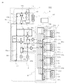
- FIG. 2 is a schematic configuration diagram illustrating an example of the configuration of the air-conditioning apparatus 100 according to Embodiment 1.
- the outdoor unit 1 and the relay unit 2 include a heat exchanger related to heat medium (refrigerant-water heat exchanger) 25 a and a heat exchanger related to heat medium (refrigerant—) provided in the relay unit 2.
- the refrigerant pipe 4 is connected via a water heat exchanger 25b.
- the relay unit 2 and the indoor unit 3 are connected to the heat exchanger related to heat medium 25a, the heat exchanger related to heat medium 25b, the heat medium flow switching device 32 (32a to 32d), and the heat medium flow switching device 33 (
- the heat medium pipes 5 are connected via 33a to 33d).
- the heat medium flow switching device 32 (32a to 32d) and the heat medium flow switching device 33 (33a to 33d) are shown as separate bodies. This is for the purpose of explaining the function of the constituent elements. Structurally, the heat medium flow switching device 32 (32a to 32d) and the heat medium flow switching device 33 (33a to 33d) are integrated.
- a heat medium flow switching device 40 (40a to 40d) is mounted.
- the number of integrated heat medium flow switching devices 40 is provided in accordance with the number of indoor units 3 installed. Here, one unit for each of the four indoor units 3, a total of four integrated heat medium flow switching devices.
- the device 40 is mounted. The present embodiment is characterized by this integrated heat medium flow switching device 40, and details will be described later.
- a compressor 10 In the outdoor unit 1, a compressor 10, a first refrigerant flow switching device 11 such as a four-way valve, a heat source side heat exchanger 12, and an accumulator 19 are mounted in series by a refrigerant pipe 4. ing. Regardless of whether the operation requested by the indoor unit 3 is heating or cooling, the refrigerant connection pipe 4a, the refrigerant connection pipe 4b, and the check are arranged in order to make the flow of the heat source side refrigerant flowing into the relay unit 2 in a certain direction. A valve 13a, a check valve 13b, a check valve 13c, and a check valve 13d are provided.
- the compressor 10 sucks the heat source side refrigerant and compresses it to bring the heat source side refrigerant into a high-pressure and high-temperature state into the refrigerant circulation channel network A (see the portion surrounded by the one-dot chain line in FIG. 2).
- an inverter compressor capable of capacity control may be used.
- the first refrigerant flow switching device 11 has a heat source side refrigerant flow during heating operation (during heating only operation mode and heating main operation mode) and a cooling operation (during cooling only operation mode and cooling main operation mode). The flow of the heat source side refrigerant is switched.
- the heat source side heat exchanger 12 functions as an evaporator during heating operation, functions as a condenser (or radiator) during cooling operation, and between air supplied from a blower such as a fan (not shown) and the heat source side refrigerant. Heat exchange is performed to evaporate or condense the heat-source-side refrigerant.
- the accumulator 19 is provided on the suction side of the compressor 10 and stores excess refrigerant due to a difference between the heating operation and the cooling operation, or excess refrigerant with respect to a transient change in operation.
- the check valve 13c is provided in a refrigerant pipe 4 (a pipe indicated by a dotted line corresponds to a relay medium 2) between the relay unit 2 and the first refrigerant flow switching device 11, and a heat medium pipe is indicated by a solid line.
- the flow of the heat source side refrigerant is allowed only in the direction (direction from the relay unit 2 to the outdoor unit 1).
- the check valve 13a is provided in the refrigerant pipe 4 between the heat source side heat exchanger 12 and the relay unit 2, and flows the heat source side refrigerant only in a predetermined direction (direction from the outdoor unit 1 to the relay unit 2). It is acceptable.
- the check valve 13d is provided in the refrigerant connection pipe 4a and causes the heat source side refrigerant discharged from the compressor 10 to flow through the relay unit 2 during the heating operation.
- the check valve 13b is provided in the refrigerant connection pipe 4b, and causes the heat source side refrigerant returned from the relay unit 2 during the heating operation to flow to the suction side of the compressor 10.
- the refrigerant connection pipe 4 a includes a refrigerant pipe 4 between the first refrigerant flow switching device 11 and the check valve 13 c, and a refrigerant pipe 4 between the check valve 13 a and the relay unit 2.
- the refrigerant connection pipe 4b includes a refrigerant pipe 4 between the check valve 13c and the relay unit 2, a refrigerant pipe 4 between the heat source side heat exchanger 12 and the check valve 13a, Are connected.
- FIG. 2 shows an example in which the refrigerant connection pipe 4a, the refrigerant connection pipe 4b, the check valve 13a, the check valve 13b, the check valve 13c, and the check valve 13d are provided.
- the present invention is not limited to this, and these are not necessarily provided.
- Each indoor unit 3 is equipped with a use side heat exchanger 35.
- the use side heat exchanger 35 is connected to the first heat medium flow switching device 32 and the second heat medium flow switching device 33 of the relay unit 2 by the heat medium pipe 5.
- the use side heat exchanger 35 exchanges heat between air supplied from a blower such as a fan (not shown) and a heat medium, and generates heating air or cooling air to be supplied to the indoor space 7. To do.
- FIG. 2 a case where four indoor units 3 are connected to the relay unit 2 is shown as an example, and are illustrated as an indoor unit 3a, an indoor unit 3b, an indoor unit 3c, and an indoor unit 3d in order from the top. ing. Further, in accordance with the indoor units 3a to 3d, the use side heat exchanger 35 is also used in order from the top, the use side heat exchanger 35a, the use side heat exchanger 35b, the use side heat exchanger 35c, and the use side heat exchanger. It is illustrated as 35d. As in FIG. 1, the number of indoor units 3 connected is not limited to the four shown in FIG.
- the relay unit 2 includes two or more heat exchangers for heat medium 25 (25a, 25b), two expansion devices 26 (26a, 26b), two switch devices (switch devices 27, 29).
- Two second refrigerant flow switching devices 28 (28a, 28b), two heat medium transfer devices 31 (31a, 31b; hereinafter referred to as pumps), and four integrated heat medium flow switching devices 40 (40a, 40b, 40c, 40d) are mounted.
- the two heat exchangers for heat medium 25 are provided with a condenser (when the heat is supplied to the indoor unit 3 performing the heating operation).
- a condenser When supplying cold heat to the indoor unit 3 that is in the cooling operation as a radiator, it functions as an evaporator, and is generated in the outdoor unit 1 by exchanging heat between the heat source side refrigerant and the heat medium.
- the cool or warm heat stored in the heat source side refrigerant is transmitted to the heat medium.
- the heat exchanger related to heat medium 25a is provided between the expansion device 26a and the second refrigerant flow switching device 28a in the refrigerant circulation channel network A, and serves to cool the heat medium in the cooling / heating mixed operation mode.
- the heat exchanger related to heat medium 25b is provided between the expansion device 26b and the second refrigerant flow switching device 28b in the refrigerant circulation channel network A, and heats the heat medium in the cooling / heating mixed operation mode. It is for use.
- the two expansion devices 26 (the expansion device 26a and the expansion device 26b) have a function as a pressure reducing valve or an expansion valve, and expand the heat source side refrigerant by reducing the pressure.
- the expansion device 26a is provided on the upstream side of the heat exchanger related to heat medium 25a in the flow of the heat source side refrigerant during the cooling operation.
- the expansion device 26b is provided on the upstream side of the heat exchanger related to heat medium 25b in the flow of the heat source side refrigerant during the cooling operation.
- the two expansion devices 26 may be constituted by devices whose opening degree can be variably controlled, for example, electronic expansion valves.
- the two opening / closing devices are configured by electromagnetic valves or the like that can be opened and closed by energization, and open / close the refrigerant pipe 4. That is, the opening and closing of the two opening / closing devices is controlled according to the operation mode, and the flow path of the heat source side refrigerant is switched.
- the opening / closing device 27 is provided in the refrigerant pipe 4 (the refrigerant pipe 4 located at the lowest stage among the refrigerant pipes 4 connecting the outdoor unit 1 and the relay unit 2) on the inlet side of the heat source side refrigerant.
- the opening / closing device 29 is provided in a pipe (bypass pipe 20) connecting the refrigerant pipe 4 on the inlet side of the heat source side refrigerant and the refrigerant pipe 4 on the outlet side.
- the opening / closing device 27 and the opening / closing device 29 may be any devices that can switch the refrigerant flow path.
- an electronic expansion valve or the like that can variably control the opening degree may be used.
- the two second refrigerant flow switching devices 28 are constituted by, for example, a four-way valve or the like, and the heat exchanger related to heat medium according to the operation mode.
- the flow of the heat source side refrigerant is switched so that 25 acts as a condenser or an evaporator.
- the second refrigerant flow switching device 28a is provided on the downstream side of the heat exchanger related to heat medium 25a in the flow of the heat source side refrigerant during the cooling operation.
- the second refrigerant flow switching device 28b is provided on the downstream side of the heat exchanger related to heat medium 25b in the flow of the heat source side refrigerant in the cooling only operation mode.
- the two pumps 31 (pump 31a, pump 31b) circulate the heat medium that conducts the heat medium pipe 5 to the heat medium circulation channel network B (see the portion surrounded by the two-dot chain line in FIG. 2). .
- the pump 31 a is provided in the heat medium pipe 5 between the heat exchanger related to heat medium 25 a and the integrated heat medium flow switching device 40.
- the pump 31 b is provided in the heat medium pipe 5 between the heat exchanger related to heat medium 25 b and the integrated heat medium flow switching device 40.
- the two pumps 31 may be configured by, for example, capacity-controllable pumps, and the flow rate thereof may be adjusted according to the load in the indoor unit 3.
- the same number of the integrated heat medium flow switching devices 40 as the indoor units 3 are provided.
- the integrated heat medium flow switching devices 40a and the integrated heat medium flow switching devices 40b are sequentially arranged from the top.
- the integrated heat medium flow switching device 40c and the integrated heat medium flow switching device 40d are illustrated.
- the integrated heat medium flow switching device 40 is configured to switch between the heat exchanger related to heat medium 25a and the heat exchanger related to heat medium 25b in accordance with the operation mode (heating operation or cooling operation) of the indoor unit 3 to which each is connected.
- the relay unit 2 is provided with a temperature sensor 55 (temperature sensor 55a, temperature sensor 55b) for detecting the temperature of the heat medium on the outlet side of the heat exchanger 25 between heat mediums.
- Information (temperature information) detected by the temperature sensor 55 is sent to a control device 50 that performs overall control of the operation of the air conditioner 100, and the drive frequency of the compressor 10, the rotational speed of the blower (not shown), and the first refrigerant flow. It is used for control such as switching of the path switching device 11, driving frequency of the pump 31, switching of the second refrigerant flow switching device 28, switching of the flow path of the heat medium, adjustment of the heat medium flow rate of the indoor unit 3, etc. Become.
- control apparatus 50 is comprised by the microcomputer etc., Based on the detection information in various detection means, and the instruction
- the heat medium pipe 5 that conducts the heat medium is composed of one connected to the heat exchanger related to heat medium 25a and one connected to the heat exchanger related to heat medium 25b.
- the heat medium pipe 5 is branched (here, four branches each) according to the number of indoor units 3 connected to the relay unit 2.
- the heat medium pipe 5 is connected to the integrated heat medium flow switching device 40. By controlling the integrated heat medium flow switching device, the heat medium from the heat exchanger related to heat medium 25a flows into the use side heat exchanger 35 or the heat medium from the heat exchanger related to heat medium 25b is used. Whether to flow into the side heat exchanger 35 is determined.
- the compressor 10 In the air conditioner 100, the compressor 10, the first refrigerant flow switching device 11, the heat source side heat exchanger 12, the switching device 27, the switching device 29, the second refrigerant flow switching device 28, and heat exchange between heat media.
- the refrigerant flow path of the container 25, the expansion device 26, and the accumulator 19 are connected by the refrigerant pipe 4 to constitute the refrigerant circulation flow path network A.
- the path switching device 33 is connected by the heat medium pipe 5 to constitute the heat medium circulation channel network B. That is, a plurality of usage-side heat exchangers 35 are connected in parallel to each of the heat exchangers 25 between heat mediums, and the heat medium circulation channel network B has a plurality of systems.
- the outdoor unit 1 and the relay unit 2 are connected via the heat exchanger related to heat medium 25a and the heat exchanger related to heat medium 25b provided in the relay unit 2, and the relay unit 2 is connected.
- the indoor unit 3 are connected via the heat exchanger related to heat medium 25a and the heat exchanger related to heat medium 25b. That is, in the air conditioner 100, the heat source side refrigerant circulating in the refrigerant circulation channel network A and the heat medium circulating in the heat medium circulation channel network B in the intermediate heat exchanger 25a and the intermediate heat exchanger 25b. And heat exchange.
- the air conditioner 100 can realize an optimal cooling operation or heating operation according to the indoor load.
- the air conditioner 100 can perform a cooling operation or a heating operation in the indoor unit 3 based on an instruction from each indoor unit 3. That is, the air conditioning apparatus 100 can perform the same operation for all the indoor units 3 and can perform different operations for each of the indoor units 3.
- the operation mode executed by the air conditioner 100 includes a heating only operation mode in which all the driven indoor units 3 execute the heating operation, and a cooling only operation in which all the driven indoor units 3 execute the cooling operation.
- each operation mode is demonstrated with the flow of a heat-source side refrigerant
- FIG. 3 is a diagram showing a configuration of a refrigerant channel network showing a refrigerant flow when the air-conditioning apparatus 100 is in the heating only operation mode.
- the heating only operation mode will be described by taking as an example a case where a thermal load is generated in all of the use side heat exchangers 35 (35a to 35d).
- the piping represented with the thick broken line has shown the piping through which the heat source side refrigerant
- the flow direction of the heat source side refrigerant is indicated by a broken line arrow, and the flow direction of the heat medium is indicated by a solid line arrow.
- the first refrigerant flow switching device 11 is configured so that the heat source side refrigerant discharged from the compressor 10 flows into the relay unit 2 without passing through the heat source side heat exchanger 12.
- the pump 31a and the pump 31b are driven to open the heat medium flow switching device 32 (32a to 32d).
- the integrated heat medium flow switching device 40 (40a to 40d)
- the heat medium circulates between the two.
- the second refrigerant flow switching device 28a and the second refrigerant flow switching device 28b are switched to the heating side, the opening / closing device 27 is closed, and the opening / closing device 29 is open.
- a low-pressure and low-temperature refrigerant is compressed by the compressor 10 and discharged as a high-pressure and high-temperature gas refrigerant.
- the high-pressure and high-temperature gas refrigerant discharged from the compressor 10 passes through the first refrigerant flow switching device 11, passes through the refrigerant connection pipe 4 a and the check valve 13 d, and flows out of the outdoor unit 1.
- the high-pressure and high-temperature gas refrigerant that has flowed out of the outdoor unit 1 flows into the relay unit 2 through the refrigerant pipe 4.
- the high-pressure and high-temperature gas refrigerant that has flowed into the relay unit 2 is branched and passes through the second refrigerant flow switching device 28a and the second refrigerant flow switching device 28b, and the heat exchanger related to heat medium 25a and heat between the heat media. It flows into each of the exchangers 25b.
- the high-pressure and high-temperature gas refrigerant that has flowed into the heat exchanger related to heat medium 25a and the heat exchanger related to heat medium 25b is condensed and liquefied while dissipating heat to the heat medium circulating in the heat medium circulation channel network B. It becomes.
- the liquid refrigerant flowing out of the heat exchanger related to heat medium 25a and the heat exchanger related to heat medium 25b is expanded by the expansion device 26a and the expansion device 26b to become a low-pressure and low-temperature two-phase refrigerant.
- These two-phase refrigerants merge, flow out of the relay unit 2 through the opening / closing device 29, and flow into the outdoor unit 1 again through the refrigerant pipe 4.
- the refrigerant that has flowed into the outdoor unit 1 passes through the refrigerant connection pipe 4b and the check valve 13b, and then flows into the heat source side heat exchanger 12 that functions as an evaporator.
- the heat-source-side refrigerant that has flowed into the heat-source-side heat exchanger 12 absorbs heat from the air in the outdoor space 6 (hereinafter referred to as “outside air”) by the heat-source-side heat exchanger 12, and becomes a low-pressure and low-temperature gas refrigerant.
- the low-pressure and low-temperature gas refrigerant flowing out from the heat source side heat exchanger 12 is again sucked into the compressor 10 via the first refrigerant flow switching device 11 and the accumulator 19.
- a technique for the purpose of energy saving during heating or cooling, a technique is used in which the temperature difference between the heat-source-side refrigerant and the load-side medium (in this case, the heat medium) is maintained constant.
- Subcool degree of supercooling obtained as a difference between the value obtained by converting the pressure of the heat source side refrigerant flowing between the exchanger 25 and the expansion device 26 into the saturation temperature and the temperature on the outlet side of the heat exchanger 25 between heat mediums
- the degree of opening of the expansion device 26 is controlled so that is constant.
- the temperature at the intermediate position of the heat exchanger related to heat medium 25 can be measured, the temperature at the intermediate position may be used instead of the converted saturation temperature. In this case, it is not necessary to install a pressure sensor, and the system can be configured at low cost.
- the heat of the heat source side refrigerant is transmitted to the heat medium in both the heat exchanger 25a and the heat exchanger 25b, and the heated heat medium is heated by the pump 31a and the pump 31b.
- the inside of the pipe 5 is allowed to flow.
- the heat medium pressurized and discharged by the pump 31a and the pump 31b flows into the use side heat exchanger 35 (35a to 35d) via the integrated heat medium flow switching device 40.
- the heat medium radiates heat to the indoor air by the use side heat exchanger 35 (35a to 35d), thereby heating the indoor space 7.
- the heat medium flows out from the use side heat exchanger 35 (35a to 35d) and flows into the integrated heat medium flow switching device 40 again.
- the flow rate adjusting action of the integrated heat medium flow switching device 40 controls the flow rate of the heat medium to a flow rate necessary to cover the air conditioning load required indoors, so that the use side heat exchanger 35 ( 35a to 35d).
- the heat medium flowing out from the integrated heat medium flow switching device 40 flows into the inter-heat medium heat exchanger 25a and the inter-heat medium heat exchanger 25b, and uses the amount of heat supplied to the indoor space 7 through the indoor unit 3 as a refrigerant. From the side and sucked into the pump 31a and the pump 31b again.
- the air conditioning load required in the indoor space 7 is the temperature detected by the temperature sensor 55a or the temperature detected by the temperature sensor 55b and the temperature of the heat medium flowing out from the use side heat exchanger 35. This can be covered by controlling the integrated heat medium flow switching device 40 so as to keep the difference at the target value.
- the outlet temperature of the heat exchanger related to heat medium 25 25a, 25b
- the temperature of either the temperature sensor 55a or the temperature sensor 55b may be used, or the average temperature thereof may be used.
- the integrated heat medium flow switching device 40 has the heat exchanger related to heat medium 25a and the heat exchangers 25a and 25b so as to secure a flow path that flows to both the heat exchanger 25a and the heat exchanger 25b.
- the opening degree is controlled according to the heat medium temperature at the outlet of the heat exchanger related to heat medium 25b.
- the usage-side heat exchanger 35 should be controlled by the temperature difference between the inlet and the outlet, but the temperature of the heat medium on the inlet side of the usage-side heat exchanger 35 is the temperature detected by the temperature sensor 55b.
- the number of temperature sensors can be reduced by using the temperature sensor 55b, and the system can be configured at low cost.
- the integrated heat medium flow switching device 40 closes the flow path.
- the heat medium is prevented from flowing to the use side heat exchanger 35.
- the heat medium flows because all of the use side heat exchangers 35 (35 a to 35 d) have a heat load, but when the heat load is lost, the corresponding integrated heat medium flow switching device What is necessary is just to fully close 40.
- the corresponding integrated heat medium flow switching device 40 may be opened and the heat medium may be circulated. The same applies to other operation modes described below.
- FIG. 4 is a diagram showing the configuration of the refrigerant flow path showing the refrigerant flow when the air-conditioning apparatus 100 is in the cooling only operation mode.
- the cooling only operation mode will be described by taking as an example a case where a cooling load is generated in all of the use side heat exchangers 35 (35a to 35d).
- the flow direction of the heat source side refrigerant is indicated by broken line arrows, and the flow direction of the heat medium is indicated by solid line arrows.
- the outdoor unit 1 switches the first refrigerant flow switching device 11 so that the heat source side refrigerant discharged from the compressor 10 flows into the heat source side heat exchanger 12.
- the pump 31a and the pump 31b are driven, the integrated heat medium switching device 40 is opened, and each of the heat exchanger related to heat medium 25a and the heat exchanger related to heat medium 25b and the use side heat exchanger 35 ( 35a-35d) is circulated between the heat medium. Further, the integrated heat medium flow switching device 40 at this time is switched to the cooling side, the opening / closing device 27 is opened, and the opening / closing device 29 is closed.
- a low-pressure and low-temperature refrigerant is compressed by the compressor 10 and discharged as a high-pressure and high-temperature gas refrigerant.
- the high-pressure and high-temperature gas refrigerant discharged from the compressor 10 passes through the first refrigerant flow switching device 11, passes through the heat source side heat exchanger 12, performs heat exchange with the outside air, and generates high-pressure and high-temperature liquid or After becoming a two-phase refrigerant and passing through the check valve 13 a, the refrigerant pipe 4 is conducted and flows out of the outdoor unit 1.
- the high-pressure and high-temperature liquid or two-phase refrigerant that has flowed into the relay unit 2 passes through the opening / closing device 27, and then is branched and expanded by the expansion device 26a and the expansion device 26b to become a low-temperature and low-pressure two-phase refrigerant. .
- These two-phase refrigerants evaporate while absorbing heat from the heat medium circulating in the heat medium circulation channel network B, and become low-temperature gas refrigerants.
- the expansion device 26 (26a, 26b) has a value obtained by converting the pressure of the heat source side refrigerant flowing between the heat exchanger 25 and the expansion device 26 into a saturation temperature, and an outlet of the heat exchanger 25.
- the opening degree is controlled so that the superheat (superheat degree) obtained as the difference from the temperature on the side becomes constant.
- the saturation temperature obtained by converting the temperature at the intermediate position may be used instead. In this case, it is not necessary to install a pressure sensor, and the system can be configured at low cost.
- the heat of the heat medium is transmitted to the heat source side refrigerant by both the heat exchangers between heat exchangers 25a and 25b, and the cooled heat medium is pressurized by the pumps 31a and 31b.
- the heat medium that has flowed out then flows into the use side heat exchanger 35 (35a to 35d) via the integrated heat medium flow switching device 40.
- the heat medium absorbs heat from the indoor air by the use side heat exchanger 35 (35a to 35d), thereby cooling the indoor space 7.
- the heat medium flows out from the use side heat exchanger 35 (35a to 35d) and flows into the integrated heat medium flow switching device 40 (40a to 40d).
- the flow rate of the heat medium and the flow rate necessary to cover the air conditioning load required in the room are controlled to the use side heat exchanger 35 (35a to 35a ⁇ ). 35d).
- the heat medium flowing out from the integrated heat medium flow switching device 40 (40a to 40d) flows into the heat exchanger related to heat medium 25a and the heat exchanger related to heat medium 25b, and absorbs heat from the indoor space 7 through the indoor unit 3. The amount of heat is transferred to the refrigerant side and again sucked into the pump 31a and the pump 31b.
- the heat medium flows in the direction from the integrated heat medium flow switching device 40 to the first heat medium flow switching device 32.
- the air conditioning load required in the indoor space 7 is the temperature detected by the temperature sensor 55a, or the temperature detected by the temperature sensor 55b and the temperature of the heat medium flowing out from the use side heat exchanger 35. This can be covered by controlling the difference to keep it at the target value.
- the outlet temperature of the heat exchanger related to heat medium 25 the temperature of either the temperature sensor 55a or the temperature sensor 55b may be used, or the average temperature thereof may be used.
- the integrated heat medium flow switching device 40 has the heat exchanger related to heat medium 25a and the heat exchangers 25a and 25b so as to secure a flow path that flows to both the heat exchanger 25a and the heat exchanger 25b.
- the opening degree is controlled according to the heat medium temperature at the outlet of the heat exchanger related to heat medium 25b.
- the usage-side heat exchanger 35 should be controlled by the temperature difference between the inlet and the outlet, but the temperature of the heat medium on the inlet side of the usage-side heat exchanger 35 is the temperature detected by the temperature sensor 55b.
- the number of temperature sensors can be reduced by using the temperature sensor 55b, and the system can be configured at low cost.
- FIG. 5 is a diagram illustrating the configuration of the refrigerant flow path that indicates the flow of the refrigerant when the air-conditioning apparatus 100 is in the mixed operation mode.
- the heating main operation mode will be described in the mixed operation in which the thermal load is generated in any one of the use side heat exchangers 35 and the remaining cooling load is generated.
- the piping represented with the thick broken line has shown the piping through which the heat source side refrigerant
- the first heat source side refrigerant discharged from the compressor 10 is allowed to flow into the relay unit 2 without passing through the heat source side heat exchanger 12.
- the refrigerant flow switching device 11 is switched.
- the pump 31 a and the pump 31 b are driven to open the integrated heat medium flow switching device 40 (40 a to 40 d), and the use side heat generated by the heat exchanger related to heat medium 25 a and the cooling load is generated.
- the heat medium is circulated between the heat exchanger 35 and the heat exchanger 35b between the heat medium and the use side heat exchanger 35 where the heat load is generated.
- the second refrigerant flow switching device 28a is switched to the cooling side, the second refrigerant flow switching device 28b is switched to the heating side, the expansion device 26a is fully opened, the opening / closing device 27 is closed, and the opening / closing device 29 is closed. ing.
- a low-temperature and low-pressure refrigerant is compressed by the compressor 10 and discharged as a high-pressure and high-temperature gas refrigerant.
- the high-pressure and high-temperature gas refrigerant discharged from the compressor 10 passes through the first refrigerant flow switching device 11, conducts the refrigerant connection pipe 4a, passes through the check valve 13d, and flows out of the outdoor unit 1.
- the high-pressure and high-temperature gas refrigerant that has flowed out of the outdoor unit 1 flows into the relay unit 2 through the refrigerant pipe 4.
- the high-pressure and high-temperature gas refrigerant that has flowed into the relay unit 2 flows into the heat exchanger related to heat medium 25b that acts as a condenser through the second refrigerant flow switching device 28b.
- the gas refrigerant flowing into the heat exchanger related to heat medium 25b condenses and liquefies while dissipating heat to the heat medium circulating in the heat medium circulation channel network B, and becomes liquid refrigerant.
- the liquid refrigerant flowing out of the heat exchanger related to heat medium 25b is expanded by the expansion device 26b and becomes a low-pressure two-phase refrigerant.
- This low-pressure two-phase refrigerant flows into the heat exchanger related to heat medium 25a acting as an evaporator via the expansion device 26a.
- the low-pressure two-phase refrigerant flowing into the heat exchanger related to heat medium 25a evaporates by absorbing heat from the heat medium circulating in the heat medium circulation channel network B, thereby cooling the heat medium.
- the low-pressure two-phase refrigerant flows out of the heat exchanger related to heat medium 25a, flows out of the relay unit 2 through the second refrigerant flow switching device 28a, and flows into the outdoor unit 1 again through the refrigerant pipe
- the low-pressure and low-temperature two-phase refrigerant that has flowed into the outdoor unit 1 flows into the heat source side heat exchanger 12 that acts as an evaporator through the check valve 13b.
- coolant which flowed into the heat source side heat exchanger 12 absorbs heat from external air in the heat source side heat exchanger 12, and turns into a low-pressure and low-temperature gas refrigerant.
- the low-pressure and low-temperature gas refrigerant flowing out from the heat source side heat exchanger 12 is again sucked into the compressor 10 via the first refrigerant flow switching device 11 and the accumulator 19.
- the opening degree of the expansion device 26b is controlled so that the subcooling (supercooling degree) of the outlet refrigerant of the heat exchanger related to heat medium 25b becomes a target value. Note that the expansion device 26b may be fully opened, and the subcool may be controlled by the expansion device 26a.
- the flow of the heat medium in the heat medium circulation channel network B will be described.
- the heat of the heat source side refrigerant is transmitted to the heat medium in the heat exchanger related to heat medium 25b, and the heated heat medium is caused to flow in the heat medium pipe 5 by the pump 31b.
- the cold heat of the heat source side refrigerant is transmitted to the heat medium in the heat exchanger related to heat medium 25a, and the cooled heat medium is caused to flow in the heat medium pipe 5 by the pump 31a.
- the cooled heat medium that has been pressurized and flowed out by the pump 31a flows into the use-side heat exchanger 35 where the cold load is generated via the integrated heat medium flow switching device 40, and is pressurized by the pump 31b.
- the heat medium that has flowed out then flows into the use side heat exchanger 35 where the heat load is generated via the integrated heat medium flow switching device 40.
- the integrated heat medium flow switching device 40 is switched to the direction in which the heat exchanger related to heat medium 25b and the pump 31b are connected when the connected indoor unit 3 is in the heating operation mode,
- the indoor unit 3 is switched to the direction in which the heat exchanger related to heat medium 25a and the pump 31a are connected. That is, the integrated heat medium flow switching device 40 can switch the heat medium supplied to the indoor unit 3 to heating or cooling.
- the cooling operation of the indoor space 7 by the heat medium absorbing heat from the room air or the heating operation of the indoor space 7 by the heat medium radiating heat to the room air is performed.
- the flow rate of the heat medium is controlled to a flow rate necessary to cover the air conditioning load required indoors by the action of the integrated heat medium flow switching device 40 and flows into the use side heat exchanger 35. It has become.
- the heat medium that has been used for the cooling operation and has passed through the use-side heat exchanger 35 and has slightly increased in temperature passes through the integrated heat medium flow switching device 40 and flows into the heat exchanger related to heat medium 25a, and is again pumped. It is sucked into 31a.
- the heat medium that has been used for the heating operation and has passed through the use side heat exchanger 35 and has slightly decreased in temperature passes through the integrated heat medium flow switching device 40 and flows into the heat exchanger related to heat medium 25b, and is again pumped. It is sucked into 31b.
- the warm heat medium and the cold heat medium are introduced into the use-side heat exchanger 35 having the heat load and the heat load, respectively, without being mixed by the action of the integrated heat medium flow switching device 40.
- the heat medium used in the heating operation mode receives heat from the refrigerant as a heating application
- the heat medium used in the cooling operation mode receives heat from the heat medium heat exchanger 25b.
- the heat exchanger 25a is fed into the heat exchanger 25a, and each heat exchanges with the refrigerant again, and then is transferred to the pump 31a and the pump 31b.
- the air conditioning load required in the indoor space 7 is the difference between the temperature detected by the temperature sensor 55b on the heating side and the temperature of the heat medium flowing out from the use side heat exchanger 35 on the cooling side. This can be covered by controlling the difference between the temperature of the heat medium flowing out from the use side heat exchanger 35 and the temperature detected by the temperature sensor 55a as a target value.
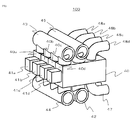
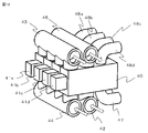
- FIG. 6 shows a conceptual diagram of the configuration of the integrated heat medium flow switching device 40 in the relay unit 2 in the air conditioner 100.
- the integrated heat medium flow switching device 40 in the relay unit 2 (not shown) in the air conditioner 100 in FIG. 6 is configured to be connected to each indoor unit connected to the relay unit 2. In this figure, it is composed of 40a to 40d. Although the number of connected devices is four here, the number of connected devices is not limited to this, and the number can be increased to a desired number.
- Each integrated heat medium flow switching device 40 is equipped with one drive device 41 (41a to 41d), and an indoor unit transfer pipe 47 and an indoor unit return pipe 48 are connected thereto. Then, the heat exchanger related to heat medium 25a (not shown), the heating heat medium transfer main pipe 44, and the heating heat medium return main pipe 45 are provided via the cooling heat medium transfer main pipe 42 and the cooling heat medium return main pipe 43. To the heat exchanger related to heat medium 25b (not shown).
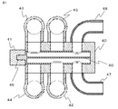
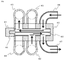
- FIG. 7 shows a cross-sectional view of the integrated heat medium flow switching device 40.
- a heat medium flow switching valve 46 is provided inside the integrated heat medium flow switching device, and the heat medium flow switching valve 46 includes a partition 60 in the internal longitudinal direction.
- the flow path for transporting the heat medium from the heat exchanger related to heat medium 25 (not shown) to the indoor unit 3 (not shown) and the indoor unit 3 are formed as flow paths for returning the heat medium from the heat exchanger 25 (not shown) to the heat exchanger related to heat medium 25 (not shown).
- the heat medium flow switching valve 46 rotates and the type of the heat medium that flows through the hole provided in the side wall of the heat medium flow switching valve, that is, the heat exchanger related to heat medium 25a ( Either one of the heat medium (not shown) or the heat exchanger related to heat medium 25b (not shown) can be selected and flowed.
- the drive device 41 uses a device capable of arbitrarily controlling the rotation angle such as a stepping motor, so that the hole in the side wall of the heat medium flow switching valve 46 and the cooling heat medium transfer main pipe 42 (cooling heat medium return).
- the opening area of the main pipe 43) or the heating medium transfer main pipe 44 (heating heat medium return main pipe 45) can be controlled, and the flow rate can be adjusted simultaneously.
- each indoor unit 3 is provided.
- the type and flow rate of the heat medium can be controlled independently.
- the operation of the integrated heat medium flow switching device 40 and the flow of the heat medium inside the operation mode of the indoor unit 3 will be described.
- the case of the mixed operation mode will be described.
- the heating only operation mode the heating heat medium is transferred to the cooling heat medium transport main pipe 42 and the cooling heat medium return main pipe 43, and in the cooling only operation mode, the heating heat medium is heated.
- a cooling heat medium is caused to flow through the transfer main pipe 44 and the heating heat medium return main pipe 45, and the operation of the integrated heat medium flow switching device 40 and the flow of the heat medium inside are the same. Is omitted.
- FIG. 8 shows the case where the indoor unit 3 (not shown) is in the cooling operation mode.
- the flow direction of the heat medium is indicated by white solid arrows.
- the flow direction of the heat medium in these main pipes is similarly set. This is indicated by a solid solid arrow.
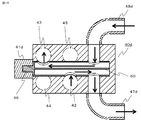
- FIG. 9 is a cross-sectional view of the integrated heat medium flow switching device 40 in which the indoor unit 3 is in the cooling operation mode, and the flow direction of the heat medium is indicated by solid arrows.
- the heat medium transmits heat to the heat source side refrigerant by a heat exchanger between heat mediums 25a (not shown), and after being cooled, is pressurized and discharged by the pump 31, and is transported by the heat medium for cooling. It flows into the integrated heat medium flow switching device 40 through the main pipe 42 for use.
- the switching valve 46 is rotated by the driving device 41 so that the cooling heat medium transfer main pipe 42 and the indoor unit transfer pipe 47, and the cooling heat medium return main pipe 43 and the indoor unit return pipe 48 communicate with each other. Thereby, the heat medium flowing through the cooling heat medium transport main pipe 42 passes through the heat medium flow switching valve 46 and is transported to the indoor unit 3 (not shown) through the indoor unit transport pipe 47. .
- the heat medium returned from the indoor unit 3 (not shown) separates the partition 60 from the heat medium that has flowed into the heat medium flow switching valve 46 in order to go to the indoor unit 3. Next to each other.
- the heat medium that has returned to the heat exchanger related to heat medium 25a (not shown) transmits the heat to the heat source side refrigerant, is cooled, and again passes through the cooling heat medium transport main pipe 42 to the integrated heat medium flow switching device 40. Will flow in.
- the above is the operation of the integrated heat medium flow switching device 40 and the flow of the heat medium inside when the indoor unit 3 (not shown) is performing the cooling operation.
- the temperature sensor 55 (not shown) provided in the relay unit 2 (not shown) and the temperature of the heat medium detected from the use side heat exchanger 35 (not shown).
- the opening area of the heat medium flow switching valve 46 and the cooling heat medium transfer main pipe 42 (cooling heat medium return main pipe 43) is controlled by the driving device 41, and the indoor unit 3 is controlled.
- the temperature of the indoor space is controlled by adjusting the flow rate of the flowing heat medium.
- FIG. 10 shows a case where the indoor unit 3 (not shown) is in the heating operation mode.
- the heating medium transfer main pipe 44, the heating heat medium return main pipe 45, the indoor unit transfer pipe 47, and the indoor unit return pipe 48 are shown.
- the flow direction of the heat medium is indicated by white solid arrows.
- the flow direction of the heat medium in these main pipes is the same. This is indicated by a solid solid arrow.
- FIG. 11 is a cross-sectional view of the integrated heat medium flow switching device 40 when the indoor unit 3 (not shown) is in the heating operation mode, and the flow direction of the heat medium is indicated by solid arrows.
- the heat medium receives heat from the heat source side refrigerant by the heat exchanger between heat mediums 25b (not shown), is heated, and then is pressurized and discharged by the pump 31 (not shown). It flows into the integrated heat medium flow switching device 40 through the heating medium conveying main pipe 44 for heating.
- the heat medium flow switching valve 46 provided in the integrated heat medium flow switching device 40 is driven. It is rotated by the apparatus 41, and the heating heat medium transfer main pipe 44 and the indoor unit transfer pipe 47, and the heating heat medium return main pipe 45 and the indoor unit return pipe 48 are communicated by the partition 60.
- the heat medium flowing through the heating heat medium transport main pipe 44 passes through the heat medium flow switching valve 46 and is transported to the indoor unit 3 through the indoor unit transport pipe 47.
- the heat medium returned from the indoor unit 3 flows into the heat medium flow switching valve 46 to be directed to the indoor unit 3 as shown in FIG. It is in a state.
- the heat medium that has returned to the heat exchanger related to heat medium 25b receives heat from the heat-source-side refrigerant, is overheated, and again passes through the heating heat medium transport main pipe 44 to be integrated with the heat medium flow switching device 40. Will flow into.
- the above is the operation of the integrated heat medium flow switching device 40 and the flow of the heat medium when the indoor unit 3 (not shown) is performing the heating operation.
- the temperature sensor 55 (not shown) provided in the relay unit 2 (not shown) and the temperature of the heat medium detected from the use side heat exchanger 35 (not shown).
- the opening area of the heat medium flow switching valve 46 and the heating medium transfer main pipe 44 (heating heat medium return main pipe 45) is controlled by the driving device 41, and the indoor unit 3 is controlled.
- the temperature of the indoor space is controlled by adjusting the flow rate of the flowing heat medium.
- FIG. 12 shows the case where the indoor unit 3 (not shown) is in the stop mode.
- the flow direction of the heat medium in the return main pipe 45 is indicated by a white solid arrow. Unlike the other operation modes described above, the flow of the heat medium in the indoor unit transfer pipe 47 and the indoor unit return pipe 48 is stopped.
- FIG. 13 is a cross-sectional view of the integrated heat medium flow switching device 40 when the indoor unit 3 is in the stop mode, and the flow direction of the heat medium is indicated by solid arrows as in FIG.
- the heat medium flow switching valve 46 includes the cooling heat medium transport main pipe 42, the cooling heat medium return main pipe 43, the heating heat medium transport main pipe 44, and the heating. The state in which there is no opening for all of the heat medium return main pipe 45, that is, the heat medium flow switching valve 46 is adjusted to an opening between the cooling operation mode and the heating operation mode.
- the heat medium is transported through the specific indoor unit 3 and the heat medium pipe 5 (not shown). It can be closed.
- the cooling operation mode, the heating operation mode, and the stop mode of the indoor unit 3 have been described.
- the integrated heat medium flow switching device 40 is provided for each indoor unit 3. Therefore, different operations for each indoor unit can be realized at the same time.
- the heat medium for example, brine (antifreeze) or water, a mixture of brine and water, a mixture of water and an additive having a high anticorrosive effect, or the like can be used. Therefore, in the air conditioner 100 (not shown), even if the heat medium leaks into the indoor space 7 (not shown) via the indoor unit 3 (not shown), the heat medium has high safety. Will contribute to improving safety.
- the heat source side heat exchanger 12 and the use side heat exchanger 35 are provided with a blower, and in many cases, condensation or evaporation is promoted by blowing air, but this is not restrictive.
- the use side heat exchanger 35 may be a panel heater using radiation, and the heat source side heat exchanger 12 is of a water-cooled type that moves heat by water or antifreeze. Can also be used. That is, the heat source side heat exchanger 12 and the use side heat exchanger 35 can be used regardless of the type as long as they have a structure capable of radiating heat or absorbing heat.
- the second refrigerant flow switching device 28 (not shown) is shown as a four-way valve, the present invention is not limited to this, and a plurality of two-way flow switching valves or three-way flow switching valves are provided. It may be configured that the refrigerant flows in the same manner.
- the drive device 41 uses a device that can arbitrarily control the rotation angle such as a stepping motor, it is not limited to this.
- a device that can be simply switched ON / OFF power source or the like may be used.
- any number of heat exchangers 25 may be installed. May be.
- the number of pumps 31a and 31b is not limited to one, and a plurality of small-capacity pumps may be connected in parallel.
- the use side heat exchanger 35 may be connected.
- the air-conditioning apparatus 100 includes the integrated heat medium flow switching device 40 that has both the heat medium switching function and the flow rate adjustment function that flow through the indoor unit 3.
- Various parts such as the number of control parts (heat medium flow switching device, heat medium flow control device), driving device, piping, and fastening parts can be reduced, and the apparatus can be downsized or the manufacturing cost can be reduced.
- the switching function and the flow rate adjustment function of the heat medium flowing through the indoor unit 3 can be simultaneously controlled by the single drive device 41, the driving power is reduced and the energy saving performance is improved.
- the integrated heat medium flow switching device 40 is closed so as not to transfer the heat medium to the indoor unit 3 in the stop mode connected to the relay unit 2.
- the conveyance power of a certain pump 31 can be reduced, and the amount of heat medium discharged at the time of parts replacement or maintenance is reduced, so that the efficiency of construction (work) is improved.
- Embodiment 2 the air conditioning apparatus 200 in Embodiment 2 of this invention is demonstrated.
- the difference between the air conditioner 200 according to the second embodiment and the air conditioner 100 according to the first embodiment is the structure of the integrated heat medium flow switching device 40, and the configuration or operation mode of the flow path and the integration. Since the operation mode of the heat medium flow switching device is the same, the same portions or corresponding portions are denoted by the same reference numerals and description thereof is omitted.
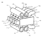
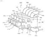
- FIG. 14 shows a conceptual diagram of a configuration of the integrated heat medium flow switching device 40 in the relay unit 2 in the air-conditioning apparatus 200 according to Embodiment 2 of the present invention.
- FIG. 15 is a cross-sectional view of an integrated heat medium flow switching device 40d provided with one drive device 41d.
- each of the integrated heat medium flow switching devices 40a to 40d includes one driving device 41a to 41d, a cooling heat medium transport main pipe 42, a cooling heat medium return main pipe 43, and a heating heat medium transport.
- the main pipe 44, the heating medium return main pipe 45, and the like are included.
- the cooling heat medium transfer main pipe 42, the cooling heat medium return main pipe 43, the heating heat medium transfer main pipe 44, and the heating heat medium return main pipe 45 are arranged adjacent to each other so as to communicate with each other. .
- the cooling heat medium transfer main pipe 42 separately from the integrated heat medium flow switching device 40, the cooling heat medium transfer main pipe 42, the cooling heat medium return main pipe 43, the heating heat medium transfer main pipe 44, and the heating heat.
- the medium return main pipe 45 There is no need to provide the medium return main pipe 45, and the number of parts can be reduced. Thereby, compared with Embodiment 1, the further size reduction of an apparatus and reduction of manufacturing cost are realizable.
- Embodiment 3 the air conditioning apparatus 300 in Embodiment 3 of this invention is demonstrated.
- the difference between the air conditioner 300 according to the third embodiment and the air conditioner 100 according to the first embodiment is that the cooling heat medium transfer main pipe 42, the cooling heat medium return main pipe 43, and the heating heat medium transfer main pipe 44.
- the structure of the heating medium return main pipe 45 for heating is the same, and the configuration or operation mode of the flow path and the operation mode of the integrated heat medium flow switching device are the same. Is omitted.
- FIG. 16 shows a conceptual diagram of the configuration of the integrated heat medium flow switching device 40 in the relay unit 2 in the air-conditioning apparatus 300 according to Embodiment 3 of the present invention.
- the cooling heat medium transfer main pipe 42, the cooling heat medium return main pipe 43, the heating heat medium transfer main pipe 44, and the heating heat medium return main pipe 45 of the integrated heat medium flow switching device 40 are divided in the longitudinal direction. It is characterized by.
- the integrated heat medium flow switching device 40 with respect to the single cooling heat medium transfer main pipe 42, the cooling heat medium return main pipe 43, the heating heat medium transfer main pipe 44, and the heating heat medium return main pipe 45 is provided.
- the number of layers 1 to 3 are preferable in consideration of degradability.
- the present invention can be freely combined with each other within the scope of the invention, and each embodiment can be appropriately modified or omitted.
- the case where a plurality of expansion devices, heat exchangers between heat media, and pumps are provided is shown.
- the present invention is not limited to this, and any one of these three types of components is singular. When two are singular, it is applicable to any case where all are singular.
- the drive device has been shown as an example in which one drive device is provided for each integrated heat medium flow switching device, but this is not a limitation, and the entire integrated heat medium flow switching device is one unit. Is also applicable.
Abstract
Description
さらに、空調対象空間の室温調整は中継ユニットから室内ユニットに搬送する熱媒体の流量制御によりなされており、室内ユニット1台につき熱媒体流量調整装置が1個必要となる。 In the air conditioner of
Further, the room temperature of the air-conditioning target space is adjusted by controlling the flow rate of the heat medium transported from the relay unit to the indoor unit, and one heat medium flow rate adjusting device is required for each indoor unit.
圧縮機、熱源側冷媒を蒸発ガス化または凝縮液化する熱源側熱交換器、流体の流量を制御する絞り装置、熱源側冷媒と利用側の熱媒体の間で熱交換を行う熱媒体間熱交換器の冷媒側配管、および冷媒の循環経路を切り替える冷媒流路切替え装置、を冷媒配管で接続して熱源側冷媒を循環させる冷媒循環流路網と、
熱媒体を加圧し搬送するポンプ、室内空間との熱交換を行う利用側熱交換器、前記熱媒体間熱交換器の熱媒体側配管を熱媒体配管で接続して熱媒体を循環させる熱媒体循環流路網と、を有し、
前記熱媒体間熱交換器において前記熱源側冷媒により加熱あるいは冷却された熱媒体と、空調対象空間の空気との間で、前記利用側熱交換器において熱交換することで前記空調対象空間の温度を制御する空気調和装置であって、
前記熱媒体間熱交換器と前記利用側熱交換器の間には一体化熱媒体流路切替え装置が配置され、当該一体化熱媒体流路切替え装置の内部には、内部長手方向に仕切りを有し、かつ側壁に穴を有した熱媒体流路切替え弁を備えており、
前記熱媒体流路切替え弁が回転動作することで、前記熱媒体間熱交換器と前記利用側熱交換器間で流す媒体である加熱あるいは冷却された熱媒体のいずれかを選択して、空気調和することを特徴とするものである。 The air conditioner according to the present invention is
Compressor, heat source side heat exchanger that evaporates or condenses the heat source side refrigerant, a throttling device that controls the flow rate of fluid, heat exchange between heat mediums that exchange heat between the heat source side refrigerant and the use side heat medium A refrigerant circulation channel network for connecting the refrigerant side piping of the storage unit and the refrigerant channel switching device for switching the circulation path of the refrigerant with the refrigerant piping to circulate the heat source side refrigerant,
A pump that pressurizes and conveys the heat medium, a use side heat exchanger that exchanges heat with the indoor space, and a heat medium that circulates the heat medium by connecting the heat medium side pipe of the heat exchanger between the heat medium with the heat medium pipe A circulation channel network,
The temperature of the air-conditioning target space is obtained by exchanging heat between the heat medium heated or cooled by the heat source-side refrigerant in the intermediate heat exchanger and the air in the air-conditioning target space in the use-side heat exchanger. An air conditioner for controlling
An integrated heat medium flow switching device is disposed between the heat exchanger between heat media and the use side heat exchanger, and the internal heat medium flow switching device is partitioned in the internal longitudinal direction. And a heat medium flow path switching valve having a hole in the side wall,
By rotating the heat medium flow switching valve, either a heated or cooled heat medium, which is a medium that flows between the heat exchanger between the heat medium and the use side heat exchanger, is selected, and air It is characterized by harmony.
以下、本願発明の実施の形態1における空気調和装置100について説明する。
図1は、本発明の実施の形態1に係る空気調和装置100の設置例を示す概略図であり、複数台の室内ユニット3を接続している空気調和装置100の全体を概略的に示している。本空気調和装置100は、冷媒(熱源側冷媒、熱媒体)を循環させる冷凍サイクル(冷媒循環流路網A、熱媒体循環流路網B)を利用することで、各室内ユニットが運転モードとして冷房モードあるいは暖房モードを自由に選択できるようになっている。空気調和装置100が実行する各運転モードとして、室内ユニット3の全てが暖房運転を実行する全暖房運転モード、室内ユニット3の全てが冷房運転を実行する全冷房運転モード、冷房暖房混在運転モードのうち暖房負荷よりも冷房負荷の方が大きい冷房主体運転モード、及び、冷房暖房混在運転モードのうち冷房負荷よりも暖房負荷の方が大きい暖房主体運転モードがあるが、詳細については後に記す。
なお、図1を含め、以下の図面では各構成部材の大きさの関係が実際のものとは異なる場合がある。
Hereinafter, the
FIG. 1 is a schematic diagram illustrating an installation example of the air-
In addition, in the following drawings including FIG. 1, the relationship of the size of each component may be different from the actual one.
室外ユニット1と中継ユニット2とは、熱源側冷媒を導通する冷媒配管4で接続されている。また、中継ユニット2と室内ユニット3とは、熱媒体を導通する熱媒体配管5で接続されている。 In FIG. 1, an
The
また、室外ユニット1、室内ユニット3及び中継ユニット2の接続台数は、図1に図示している台数に限定するものではなく、空調対象空間の数あるいは容積に応じて台数を決定すればよい。 Further, the
Further, the number of connected
図2では熱媒体流路切替え装置32(32a~32d)と熱媒体流路切替え装置33(33a~33d)を別体に示しているが、これは空気調和装置100の熱媒体流路の各構成要素の機能を説明するためであり、構造的には、熱媒体流路切替え装置32(32a~32d)と熱媒体流路切替え装置33(33a~33d)とを一体化した構成の一体化熱媒体流路切替え装置40(40a~40d)を搭載している。
一体化熱媒体流路切替え装置40は室内ユニット3の設置台数に応じた個数が設けられ、ここでは4台の室内ユニット3に対してそれぞれ1台、計4台の一体化熱媒体流路切替え装置40を搭載している。本実施の形態は、この一体化熱媒体流路切替え装置40に特徴があるが、詳細は後述する。 FIG. 2 is a schematic configuration diagram illustrating an example of the configuration of the air-
In FIG. 2, the heat medium flow switching device 32 (32a to 32d) and the heat medium flow switching device 33 (33a to 33d) are shown as separate bodies. This is for the purpose of explaining the function of the constituent elements. Structurally, the heat medium flow switching device 32 (32a to 32d) and the heat medium flow switching device 33 (33a to 33d) are integrated. A heat medium flow switching device 40 (40a to 40d) is mounted.
The number of integrated heat medium
室外ユニット1には、圧縮機10と、四方弁等の第1冷媒流路切替え装置11と、熱源側熱交換器12と、アキュムレーター19とが、冷媒配管4で直列に接続されて搭載されている。また、室内ユニット3の要求する運転が暖房または冷房に関わらず、中継ユニット2に流入させる熱源側冷媒の流れを一定方向にするために、冷媒用接続配管4a、冷媒用接続配管4b、逆止弁13a、逆止弁13b、逆止弁13c、及び、逆止弁13dを設けている。 [Outdoor unit]
In the
室内ユニット3には、それぞれ利用側熱交換器35が搭載されている。この利用側熱交換器35は、熱媒体配管5によって中継ユニット2の第1熱媒体流路切替え装置32と第2熱媒体流路切替え装置33に接続するようになっている。この利用側熱交換器35は、図示省略のファン等の送風機から供給される空気と熱媒体との間で熱交換を行ない、室内空間7に供給するための暖房用空気あるいは冷房用空気を生成するものである。 [Indoor unit]
Each
中継ユニット2には、2つ以上の熱媒体間熱交換器25(25a、25b)と、2つの絞り装置26(26a、26b)と、2つの開閉装置(開閉装置27、開閉装置29)と、2つの第2冷媒流路切替え装置28(28a、28b)と、2つの熱媒体搬送装置であるポンプ31(31a、31b。以下ポンプと呼ぶ)と、4つの一体化熱媒体流路切替え装置40(40a、40b、40c、40d)と、が搭載されている。 [Relay unit]
The
空気調和装置100が実行する各運転モードについて説明する。この空気調和装置100は、各室内ユニット3からの指示に基づいて、その室内ユニット3で冷房運転あるいは暖房運転が可能になっている。つまり、空気調和装置100は、室内ユニット3の全部で同一運転をすることができるとともに、室内ユニット3のそれぞれで異なる運転をすることができるようになっている。 [Operation mode]
Each operation mode which the
図3は、空気調和装置100の全暖房運転モード時における冷媒の流れを示す冷媒流路網の構成を示す図である。ここでは、利用側熱交換器35(35a~35d)の全部で温熱負荷が発生している場合を例に全暖房運転モードについて説明する。なお、図3では、太い破線で表された配管が熱源側冷媒の流れる配管を示している。また、熱源側冷媒の流れ方向を破線矢印で、熱媒体の流れ方向を実線矢印で示している。 [Heating operation mode]
FIG. 3 is a diagram showing a configuration of a refrigerant channel network showing a refrigerant flow when the air-
低圧かつ低温の冷媒が圧縮機10によって圧縮され、高圧かつ高温のガス冷媒となって吐出される。圧縮機10から吐出された高圧かつ高温のガス冷媒は、第1冷媒流路切替え装置11を通り、冷媒用接続配管4aおよび逆止弁13dを通過し、室外ユニット1から流出する。室外ユニット1から流出した高圧かつ高温のガス冷媒は、冷媒配管4を通って中継ユニット2に流入する。中継ユニット2に流入した高圧かつ高温のガス冷媒は、分岐されて第2冷媒流路切替え装置28a及び第2冷媒流路切替え装置28bを通って、熱媒体間熱交換器25a及び熱媒体間熱交換器25bのそれぞれに流入する。 First, the flow of the heat source side refrigerant in the refrigerant circulation channel network A will be described.
A low-pressure and low-temperature refrigerant is compressed by the
全暖房運転モードでは、熱媒体間熱交換器25a及び熱媒体間熱交換器25bの双方で熱源側冷媒の温熱が熱媒体に伝えられ、暖められた熱媒体がポンプ31a及びポンプ31bによって熱媒体配管5内を流動させられることになる。ポンプ31a及びポンプ31bで加圧されて流出した熱媒体は、一体化熱媒体流路切替え装置40を介して、利用側熱交換器35(35a~35d)に流入する。そして、熱媒体が利用側熱交換器35(35a~35d)で室内空気に放熱することで、室内空間7の暖房を行なう。 Next, the flow of the heat medium in the heat medium circulation channel network B will be described.
In the all-heating operation mode, the heat of the heat source side refrigerant is transmitted to the heat medium in both the
図4は、空気調和装置100の全冷房運転モード時における冷媒の流れを示す冷媒流路の構成を示す図である。ここでは、利用側熱交換器35(35a~35d)の全部で冷熱負荷が発生している場合を例に全冷房運転モードについて説明する。なお、図4では熱源側冷媒の流れ方向を破線矢印で、熱媒体の流れ方向を実線矢印で示している。 [Cooling operation mode]
FIG. 4 is a diagram showing the configuration of the refrigerant flow path showing the refrigerant flow when the air-
低圧かつ低温の冷媒が圧縮機10によって圧縮され、高圧かつ高温のガス冷媒となって吐出される。圧縮機10から吐出された高圧かつ高温のガス冷媒は、第1冷媒流路切替え装置11を通り、熱源側熱交換器12を通過し、外気との熱交換を行い、高圧かつ高温の液または二相冷媒となり、逆止弁13aを通過した後、冷媒配管4を導通し室外ユニット1から流出する。室外ユニット1から流出した高圧かつ高温の液または二相冷媒は、冷媒配管4を通って中継ユニット2に流入する。中継ユニット2に流入した高圧かつ高温の液または二相冷媒は、開閉装置27を通過した後、分岐されて絞り装置26aおよび絞り装置26bで膨張させられて、低温かつ低圧の二相冷媒となる。これらの二相冷媒は、熱媒体循環流路網Bを循環する熱媒体から吸熱しながら蒸発気化し、低温のガス冷媒となる。熱媒体間熱交換器25aおよび熱媒体間熱交換器25bから流出したガス冷媒は、第2冷媒流路切替え装置28aおよび第2冷媒流路切替え装置28bを通って中継ユニット2から流出し、冷媒用接続配管4b、逆止弁13bを通過して第1冷媒流路切替え装置11およびアキュムレーター19を介して圧縮機10へ再度、吸入される。
このとき絞り装置26(26a、26b)は、熱媒体間熱交換器25と絞り装置26との間を流れる熱源側冷媒の圧力を飽和温度換算した値と、熱媒体間熱交換器25の出口側の温度との差として得られるスーパーヒート(過熱度)が一定になるように開度が制御される。なお、熱媒体間熱交換器25の中間位置の温度が測定できる場合は、その中間位置での温度を換算した飽和温度を変わりに用いてもよい。この場合、圧力センサを設置しなくて済み、安価にシステムを構成できる。 First, the flow of the heat source side refrigerant in the refrigerant circulation channel network A will be described.
A low-pressure and low-temperature refrigerant is compressed by the
At this time, the expansion device 26 (26a, 26b) has a value obtained by converting the pressure of the heat source side refrigerant flowing between the heat exchanger 25 and the expansion device 26 into a saturation temperature, and an outlet of the heat exchanger 25. The opening degree is controlled so that the superheat (superheat degree) obtained as the difference from the temperature on the side becomes constant. In addition, when the temperature of the intermediate position of the intermediate heat exchanger 25 can be measured, the saturation temperature obtained by converting the temperature at the intermediate position may be used instead. In this case, it is not necessary to install a pressure sensor, and the system can be configured at low cost.
全冷房運転モードでは、熱媒体間熱交換器25aおよび熱媒体間熱交換器25bの双方で熱源側冷媒へ熱媒体の温熱が伝えられ、冷却された熱媒体がポンプ31aおよびポンプ31bで加圧されて流出した熱媒体は、一体化熱媒体流路切替え装置40を介して、利用側熱交換器35(35a~35d)に流入する。そして、熱媒体が利用側熱交換器35(35a~35d)で室内空気から吸熱することで、室内空間7の冷房を行う。 Next, the flow of the heat medium in the heat medium circulation channel network B will be described.
In the cooling only operation mode, the heat of the heat medium is transmitted to the heat source side refrigerant by both the heat exchangers between
図5は、空気調和装置100の混在運転モード時における冷媒の流れを示す冷媒流路の構成を示す図である。この図5では、利用側熱交換器35のうちのいずれかで温熱負荷が発生し、残りで冷熱負荷が発生している混在運転のうち、暖房主体運転モードについて説明する。なお、図5では、太い破線で表された配管が熱源側冷媒の循環する配管を示している。また、熱源側冷媒の流れ方向を破線矢印で、熱媒体の流れ方向を実線矢印で示している。 [Mixed operation mode]
FIG. 5 is a diagram illustrating the configuration of the refrigerant flow path that indicates the flow of the refrigerant when the air-
低温かつ低圧の冷媒が圧縮機10によって圧縮され、高圧かつ高温のガス冷媒となって吐出される。圧縮機10から吐出された高圧かつ高温のガス冷媒は、第1冷媒流路切替え装置11を通り、冷媒用接続配管4aを導通し、逆止弁13dを通過し、室外ユニット1から流出する。室外ユニット1から流出した高圧かつ高温のガス冷媒は、冷媒配管4を通って中継ユニット2に流入する。中継ユニット2に流入した高圧かつ高温のガス冷媒は、第2冷媒流路切替え装置28bを通って凝縮器として作用する熱媒体間熱交換器25bに流入する。 First, the flow of the heat source side refrigerant in the refrigerant circulation channel network A will be described.
A low-temperature and low-pressure refrigerant is compressed by the
第1暖房主体運転モードでは、熱媒体間熱交換器25bで熱源側冷媒の温熱が熱媒体に伝えられ、暖められた熱媒体がポンプ31bによって熱媒体配管5内を流動させられることになる。また、第1暖房主体運転モードでは、熱媒体間熱交換器25aで熱源側冷媒の冷熱が熱媒体に伝えられ、冷やされた熱媒体がポンプ31aによって熱媒体配管5内を流動させられることになる。ポンプ31aで加圧されて流出した冷やされた熱媒体は、冷熱負荷が発生している利用側熱交換器35に一体化熱媒体流路切替え装置40を介して流入し、ポンプ31bで加圧されて流出した熱媒体は、温熱負荷が発生している利用側熱交換器35に一体化熱媒体流路切替え装置40を介して流入する。 Next, the flow of the heat medium in the heat medium circulation channel network B will be described.
In the first heating main operation mode, the heat of the heat source side refrigerant is transmitted to the heat medium in the heat exchanger related to
図8は、室内ユニット3(図示せず)が冷房運転モードの場合であり、冷房用熱媒体搬送用主管42、冷房用熱媒体戻り主管43、室内ユニット搬送用配管47、室内ユニット戻り配管48の熱媒体の流れ方向を白抜き実線矢印で示している。なお、暖房用熱媒体搬送用主管44、暖房用熱媒体戻り主管45の内部にも、熱媒体が常時流れているのが通常であるため、これらの主管での熱媒体の流れ方向を同様に白抜き実線矢印で示している。 [Cooling operation mode]
FIG. 8 shows the case where the indoor unit 3 (not shown) is in the cooling operation mode. The cooling heat medium transfer
図10は、室内ユニット3(図示せず)が暖房運転モードの場合であり、暖房用熱媒体搬送用主管44、暖房用熱媒体戻り主管45、室内ユニット搬送用配管47、室内ユニット戻り配管48の熱媒体の流れ方向を白抜き実線矢印で示している。なお、冷房用熱媒体搬送用主管42、冷房用熱媒体戻り主管43の内部にも、熱媒体が常時流れているのが通常であるため、これらの主管での熱媒体の流れ方向を同様に白抜き実線矢印で示している。 [Heating operation mode]
FIG. 10 shows a case where the indoor unit 3 (not shown) is in the heating operation mode. The heating medium transfer
図12は、室内ユニット3(図示せず)が停止モードの場合であり、冷房用熱媒体搬送用主管42、冷房用熱媒体戻り主管43、暖房用熱媒体搬送用主管44、暖房用熱媒体戻り主管45の熱媒体の流れ方向を白抜き実線矢印で示している。上述の他の運転モードと異なり、室内ユニット搬送用配管47、室内ユニット戻り配管48の熱媒体の流動は停止している。 [Stop mode]
FIG. 12 shows the case where the indoor unit 3 (not shown) is in the stop mode. The cooling heat medium transfer
さらには、一体化熱媒体流路切替え装置40を、中継ユニット2に接続された停止モード中の室内ユニット3に対して熱媒体の搬送を行わないように閉止することで、熱媒体搬送装置であるポンプ31の搬送動力を削減することが出来ると共に、部品交換時あるいはメンテナンス時においての熱媒体排出量の削減にも繋がり、工事(作業)の効率が向上する。 As described above, the air-
Furthermore, the integrated heat medium
以下、本願発明の実施の形態2における空気調和装置200について説明する。本実施の形態2の空気調和装置200と上記実施の形態1の空気調和装置100の差異は、一体化熱媒体流路切替え装置40の構造であり、流路の構成あるいは運転モードおよび、一体化熱媒体流路切替え装置の運転モードは同様のため、同一部分もしくは相当部分は同一符号を付し説明を省略する。
Hereinafter, the
以下、本願発明の実施の形態3における空気調和装置300について説明する。本実施の形態3の空気調和装置300と上記実施の形態1の空気調和装置100の差異は、冷房用熱媒体搬送用主管42、冷房用熱媒体戻り主管43、暖房用熱媒体搬送用主管44、暖房用熱媒体戻り主管45の構造であり、流路の構成あるいは運転モードおよび、一体化熱媒体流路切替え装置の運転モードは同様のため、同一部分もしくは相当部分は同一符号を付し説明を省略する。
Hereinafter, the
1 outdoor unit, 2 relay unit, 3 indoor unit, 3a indoor unit, 3b indoor unit, 3c indoor unit, 3d indoor unit, 4 refrigerant pipe, 4a refrigerant connection pipe, 4b refrigerant connection pipe, 5 heat medium pipe, 6 Outdoor space, 7 indoor space, 8 ceiling, 9 building, 10 compressor, 11 first refrigerant flow switching device, 12 heat source side heat exchanger, 13a check valve, 13b check valve, 13c check valve, 13d Check valve, 19 Accumulator, 20 Bypass pipe, 25 Heat exchanger between heat media, 25a Heat exchanger between heat media, 25b Heat exchanger between heat media, 26 Throttle device, 26a Throttle device, 26b Throttle device, 27 Open / close 28, second refrigerant flow switching device, 28a second refrigerant flow switching device, 28b second refrigerant flow switching device, 29 opening / closing device, 31 pump, 31a pump, 3 1b pump, 32 first heat medium flow switching device, 32a first heat medium flow switching device, 32b first heat medium flow switching device, 32c first heat medium flow switching device, 32d first heat medium flow switching Switching device, 33 second heat medium flow switching device, 33a second heat medium flow switching device, 33b second heat medium flow switching device, 33c second heat medium flow switching device, 33d second heat medium flow switching Switching device, 35 utilization side heat exchanger, 35a utilization side heat exchanger, 35b utilization side heat exchanger, 35c utilization side heat exchanger, 35d utilization side heat exchanger, 40 integrated heat medium flow switching device, 41 drive Equipment, 42 Heating medium transfer main pipe for cooling, 43 Heating medium return main pipe for cooling, 44 Heating medium transfer main pipe for heating, 45 Heating medium return main pipe for heating, 46 Heat medium flow switching valve, 47 Indoor unit transfer piping 48 rooms Unit return piping, 50 control device, 55 temperature sensor, 55a temperature sensor, 55b temperature sensor, 60 partition, 100, 200, 300 air conditioner, A refrigerant circulation channel network, B heat medium circulation channel network.
Claims (9)
- 圧縮機、熱源側冷媒を蒸発ガス化または凝縮液化する熱源側熱交換器、流体の流量を制御する絞り装置、熱源側冷媒と利用側の熱媒体の間で熱交換を行う熱媒体間熱交換器の冷媒側配管、および冷媒の循環経路を切り替える冷媒流路切替え装置、を冷媒配管で接続して熱源側冷媒を循環させる冷媒循環流路網と、
熱媒体を加圧し搬送するポンプ、室内空間との熱交換を行う利用側熱交換器、前記熱媒体間熱交換器の熱媒体側配管を熱媒体配管で接続して熱媒体を循環させる熱媒体循環流路網と、を有し、
前記熱媒体間熱交換器において前記熱源側冷媒により加熱あるいは冷却された熱媒体と、空調対象空間の空気との間で、前記利用側熱交換器において熱交換することで前記空調対象空間の温度を制御する空気調和装置であって、
前記熱媒体間熱交換器と前記利用側熱交換器の間には一体化熱媒体流路切替え装置が配置され、当該一体化熱媒体流路切替え装置の内部には、内部長手方向に仕切りを有し、かつ側壁に穴を有した熱媒体流路切替え弁を備えており、
前記熱媒体流路切替え弁が回転動作することで、前記熱媒体間熱交換器と前記利用側熱交換器間で流す媒体である加熱あるいは冷却された熱媒体のいずれかを選択して、空気調和することを特徴とする空気調和装置。 Compressor, heat source side heat exchanger that evaporates or condenses the heat source side refrigerant, a throttling device that controls the flow rate of fluid, heat exchange between heat mediums that exchange heat between the heat source side refrigerant and the use side heat medium A refrigerant circulation channel network for connecting the refrigerant side piping of the storage unit and the refrigerant channel switching device for switching the circulation path of the refrigerant with the refrigerant piping to circulate the heat source side refrigerant,
A pump that pressurizes and conveys the heat medium, a use side heat exchanger that exchanges heat with the indoor space, and a heat medium that circulates the heat medium by connecting the heat medium side pipe of the heat exchanger between the heat medium with the heat medium pipe A circulation channel network,
The temperature of the air-conditioning target space is obtained by exchanging heat between the heat medium heated or cooled by the heat source-side refrigerant in the intermediate heat exchanger and the air in the air-conditioning target space in the use-side heat exchanger. An air conditioner for controlling
An integrated heat medium flow switching device is disposed between the heat exchanger between heat media and the use side heat exchanger, and the internal heat medium flow switching device is partitioned in the internal longitudinal direction. And a heat medium flow path switching valve having a hole in the side wall,
By rotating the heat medium flow switching valve, either a heated or cooled heat medium, which is a medium that flows between the heat exchanger between the heat medium and the use side heat exchanger, is selected, and air An air conditioner characterized by harmony. - 前記利用側熱交換器が複数設置されている場合において、前記利用側熱交換器の台数と同数以下の前記一体化熱媒体流路切替え装置を備え、前記熱媒体間熱交換器のすべてが凝縮器として作用する全暖房運転モードと、前記熱媒体間熱交換器のすべてが蒸発器として作用する全冷房運転モードと、前記熱媒体間熱交換器の一部が凝縮器として作用し、前記熱媒体間熱交換器の一部が蒸発器として作用する冷房暖房運転混在運転モードを実現する請求項1に記載の空気調和装置。 In the case where a plurality of the use side heat exchangers are installed, the number of the use side heat exchangers is equal to or less than the number of the integrated heat medium flow switching devices, and all the heat exchangers between the heat media are condensed. A heating only operation mode that acts as a heat exchanger, a cooling only operation mode in which all of the heat exchanger related to heat medium acts as an evaporator, a part of the heat exchanger related to heat medium acts as a condenser, and the heat The air conditioner according to claim 1, wherein a mixed operation mode of cooling and heating operation in which a part of the heat exchanger between mediums functions as an evaporator is realized.
- 前記各運転モードにおいて、各運転モードを実施中に、前記熱媒体間熱交換器と前記利用側熱交換器間で流れる熱媒体の流量を制御することを特徴とする請求項2に記載の空気調和装置。 3. The air according to claim 2, wherein the flow rate of the heat medium flowing between the heat exchanger related to heat medium and the heat exchanger on the use side is controlled during the operation of each operation mode. Harmony device.
- 前記一体化熱媒体流路切替え装置に備えた単一の駆動装置により、前記熱媒体間熱交換器に設置した温度センサと前記利用側熱交換器で検出した熱媒体の温度差を目標値に保つように、熱媒体の切替えと流量調整を同時に行うことを特徴とする請求項3に記載の空気調和装置。 By using a single drive device provided in the integrated heat medium flow switching device, the temperature difference between the temperature sensor installed in the heat exchanger between the heat medium and the heat medium detected by the use-side heat exchanger is set as a target value. The air conditioner according to claim 3, wherein the heat medium is switched and the flow rate is adjusted at the same time so as to maintain.
- 前記各運転モードにおいて、複数の一体化熱媒体流路切替え装置内の一部もしくは全ての駆動装置を制御して流路を閉塞することにより、前記熱媒体間熱交換器と前記利用側熱交換器間の熱媒体の流路を遮断することを特徴とする請求項3または4に記載の空気調和装置。 In each of the operation modes, the heat exchanger between the heat medium and the use side heat exchange is controlled by controlling a part or all of the drive devices in the plurality of integrated heat medium flow switching devices to close the flow passage. The air conditioner according to claim 3 or 4, wherein a flow path of a heat medium between the units is blocked.
- 前記冷媒循環流路網に供給される冷媒は、単一冷媒、擬似共沸混合冷媒、非共沸混合冷媒、自然冷媒を含む二相変化を伴う冷媒、あるいは超臨界となる冷媒であることを特徴とする請求項1から5のいずれか1項に記載の空気調和装置。 The refrigerant supplied to the refrigerant circulation channel network is a single refrigerant, a pseudo-azeotropic mixed refrigerant, a non-azeotropic mixed refrigerant, a refrigerant with a two-phase change including a natural refrigerant, or a supercritical refrigerant. The air conditioner according to any one of claims 1 to 5, characterized in that
- 前記熱媒体循環流路網に供給される熱媒体は、不凍液、あるいは水との防食効果が高い添加剤の混合液で構成することを特徴とする請求項1から6のいずれか1項に記載の空気調和装置。 The heat medium supplied to the heat medium circulation channel network is composed of an antifreeze liquid or a mixed liquid of an additive having a high anticorrosive effect with water. Air conditioner.
- 前記一体化熱媒体流路切替え装置に、加熱および冷却された熱媒体の流路の一部を形成し、これが連通するように一体化熱媒体流路切替え装置を構成することで熱媒体の流路を形成したことを特徴とする請求項1から7のいずれか1項に記載の空気調和装置。 A part of the heated and cooled heat medium flow path is formed in the integrated heat medium flow path switching device, and the integrated heat medium flow path switching device is configured so as to communicate therewith. The air conditioning apparatus according to any one of claims 1 to 7, wherein a path is formed.
- 前記一体化熱媒体流路切替え装置を接続する、加熱および冷却された熱媒体が流れる配管を、連通するように構成することで、熱媒体の流路を成形し、熱媒体流路切替え装置の数量を変更可能としたことを特徴とする請求項1から7のいずれか1項に記載の空気調和装置。
A pipe for connecting the integrated heat medium flow switching device, through which the heated and cooled heat medium flows, is configured to communicate with each other, thereby forming a heat medium flow path. The air conditioner according to any one of claims 1 to 7, wherein the quantity can be changed.
Priority Applications (4)
| Application Number | Priority Date | Filing Date | Title |
|---|---|---|---|
| CN201580033319.7A CN106537063B (en) | 2014-07-18 | 2015-06-09 | Air-conditioning device |
| JP2016534323A JP6385436B2 (en) | 2014-07-18 | 2015-06-09 | Air conditioner |
| EP15822339.6A EP3171097B1 (en) | 2014-07-18 | 2015-06-09 | Air conditioner |
| US15/314,022 US10215452B2 (en) | 2014-07-18 | 2015-06-09 | Air conditioner |
Applications Claiming Priority (2)
| Application Number | Priority Date | Filing Date | Title |
|---|---|---|---|
| JP2014-147434 | 2014-07-18 | ||
| JP2014147434 | 2014-07-18 |
Publications (1)
| Publication Number | Publication Date |
|---|---|
| WO2016009748A1 true WO2016009748A1 (en) | 2016-01-21 |
Family
ID=55078250
Family Applications (1)
| Application Number | Title | Priority Date | Filing Date |
|---|---|---|---|
| PCT/JP2015/066600 WO2016009748A1 (en) | 2014-07-18 | 2015-06-09 | Air conditioner |
Country Status (5)
| Country | Link |
|---|---|
| US (1) | US10215452B2 (en) |
| EP (1) | EP3171097B1 (en) |
| JP (1) | JP6385436B2 (en) |
| CN (1) | CN106537063B (en) |
| WO (1) | WO2016009748A1 (en) |
Cited By (4)
| Publication number | Priority date | Publication date | Assignee | Title |
|---|---|---|---|---|
| WO2019155548A1 (en) * | 2018-02-07 | 2019-08-15 | 三菱電機株式会社 | Air conditioning system and air conditioning control method |
| WO2019155506A1 (en) * | 2018-02-06 | 2019-08-15 | 三菱電機株式会社 | Air conditioning system |
| DE112017002894B4 (en) | 2016-06-08 | 2023-05-04 | Denso Corporation | switching valve |
| JP7377362B2 (en) | 2019-12-26 | 2023-11-09 | エルジー エレクトロニクス インコーポレイティド | air conditioner |
Families Citing this family (16)
| Publication number | Priority date | Publication date | Assignee | Title |
|---|---|---|---|---|
| CN106255849B (en) | 2014-07-18 | 2019-10-22 | 三菱电机株式会社 | Thermal medium flow passage selector device and the air-conditioning device for having the thermal medium flow passage selector device |
| EP3171097B1 (en) | 2014-07-18 | 2019-11-06 | Mitsubishi Electric Corporation | Air conditioner |
| WO2016027541A1 (en) * | 2014-08-22 | 2016-02-25 | 三菱電機株式会社 | Compound valve |
| JP6609417B2 (en) * | 2015-04-03 | 2019-11-20 | 日立ジョンソンコントロールズ空調株式会社 | Air conditioner |
| CN109210239B (en) * | 2017-07-03 | 2020-08-11 | 浙江三花制冷集团有限公司 | Rotary reversing valve and refrigerating system thereof |
| CN111433549A (en) | 2017-07-17 | 2020-07-17 | 分形散热器技术有限责任公司 | Multi-fractal heat sink system and method |
| CN108775728B (en) * | 2018-07-20 | 2023-08-04 | 珠海格力电器股份有限公司 | Multi-split water chiller-heater unit |
| KR20200114123A (en) * | 2019-03-27 | 2020-10-07 | 엘지전자 주식회사 | An air conditioning apparatus |
| KR20200134805A (en) | 2019-05-23 | 2020-12-02 | 엘지전자 주식회사 | An air conditioning apparatus |
| CN113587483A (en) * | 2020-04-30 | 2021-11-02 | 李建军 | Refrigerant reverse circulation cold-heat exchange energy-saving synergistic system |
| JP7306582B2 (en) * | 2020-05-28 | 2023-07-11 | 三菱電機株式会社 | refrigeration cycle equipment |
| KR20220043596A (en) * | 2020-09-29 | 2022-04-05 | 엘지전자 주식회사 | Flow path switching apparatus |
| KR20220043595A (en) * | 2020-09-29 | 2022-04-05 | 엘지전자 주식회사 | Flow path switching apparatus |
| CN112477549B (en) * | 2020-11-23 | 2022-03-18 | 艾泰斯热系统研发(上海)有限公司 | Cooling liquid cooling heat source switching device of multi-load heat pump system |
| CN113108428B (en) * | 2021-04-13 | 2023-03-17 | 广州市水电设备安装有限公司 | Multi-split central air conditioning system and control method thereof |
| CN113915788A (en) * | 2021-10-22 | 2022-01-11 | 上海爱斯达克汽车空调系统有限公司 | Heat pump system integrated structure |
Citations (7)
| Publication number | Priority date | Publication date | Assignee | Title |
|---|---|---|---|---|
| JP3049769U (en) * | 1997-12-15 | 1998-06-26 | ウエン ル チ | Water flow switching valve for filter |
| JP2007309333A (en) * | 2004-12-03 | 2007-11-29 | Koichi Kawakami | Five-way valve |
| WO2010119555A1 (en) * | 2009-04-17 | 2010-10-21 | 三菱電機株式会社 | Heating medium converter and air-conditioning device |
| JP2011043188A (en) * | 2009-08-20 | 2011-03-03 | Fuji Koki Corp | Composite valve |
| WO2012070192A1 (en) * | 2010-11-24 | 2012-05-31 | 三菱電機株式会社 | Air conditioner |
| WO2014128962A1 (en) * | 2013-02-25 | 2014-08-28 | 三菱電機株式会社 | Air conditioner |
| WO2014128961A1 (en) * | 2013-02-25 | 2014-08-28 | 三菱電機株式会社 | Air conditioner |
Family Cites Families (63)
| Publication number | Priority date | Publication date | Assignee | Title |
|---|---|---|---|---|
| US2533931A (en) | 1944-12-05 | 1950-12-12 | Parker Appliance Co | Valve assembly |
| US2678062A (en) | 1952-03-03 | 1954-05-11 | George L Macneill | Fluid reversing device |
| GB821898A (en) | 1957-06-25 | 1959-10-14 | Crosse & Blackwell Ltd | Improvements relating to rotary valves |
| US3098506A (en) | 1958-10-02 | 1963-07-23 | Martin Sweets Company | Valve packing assembly |
| US3021869A (en) | 1959-07-30 | 1962-02-20 | James F Ross | Rotary type hydraulic valve |
| US3190584A (en) | 1962-08-02 | 1965-06-22 | Snecma | Fluid distribution device especially applicable to control by jet of v.t.o.l. aircraft |
| US3199539A (en) | 1963-07-12 | 1965-08-10 | Mckinley B Leathem | Proportioning control valve for hydraulic cylinders |
| US3918493A (en) | 1972-03-01 | 1975-11-11 | John D Tobias | Valve construction |
| US4055151A (en) | 1973-08-21 | 1977-10-25 | Clarke Chapman, Ltd. | Waste heat boiler |
| JPS5183932U (en) * | 1974-12-27 | 1976-07-06 | ||
| JPS52106642U (en) * | 1977-02-10 | 1977-08-13 | ||
| SE437556B (en) | 1978-11-24 | 1985-03-04 | Henningsson Ab Ing T | VALVE FOR PRESETTING OF THE OPERATING MEDIUM FOR A RADIATOR AND FOR SETTING THE FLOW OF THE HEATING MEDIUM THROUGH THE RADIATOR |
| US4355659A (en) | 1981-01-08 | 1982-10-26 | The Hilliard Corp. | Rotary plug valve |
| US4445540A (en) | 1981-10-27 | 1984-05-01 | Water Services Of America, Inc. | Sleeve-type fluid flow diverter |
| US4506703A (en) | 1983-03-14 | 1985-03-26 | Water Services Of America, Inc. | Four-way fluid flow diverter valve |
| JPS6097598U (en) | 1983-12-12 | 1985-07-03 | 東信精機株式会社 | Clothes finishing machine ventilation switching device |
| US4658859A (en) | 1984-12-07 | 1987-04-21 | South Bend Lathe, Inc. | Valve spool with cross drill ports |
| US4716923A (en) | 1986-06-27 | 1988-01-05 | West Robert E | Apparatus for manipulating parallel fluid flow circuits |
| US4986307A (en) | 1989-08-02 | 1991-01-22 | The United States Of America As Represented By The United States Department Of Energy | Rotary pneumatic valve |
| FR2656668B1 (en) | 1989-12-28 | 1992-04-17 | Losego Martine | AUTOMATIC THERMOSTATIC MIXER WITH INCORPORATED REDUCER. |
| US5172725A (en) | 1992-01-17 | 1992-12-22 | Isao Kitagawa | Device for switching the flow direction of fluid |
| DE19507919A1 (en) | 1995-03-07 | 1996-09-12 | Buderus Heiztechnik Gmbh | Central changeover unit for fluid currents for periodically alternating series switching heat exchanger modules |
| US5820133A (en) | 1996-03-15 | 1998-10-13 | Fleck Controls, Inc. | Rotary control valve and seal mechanism |
| US5868165A (en) | 1997-01-08 | 1999-02-09 | Tranovich; Stephen J. | Rotary metering-pin servovalve and method of manufacturing the same |
| US6308739B1 (en) | 1998-02-13 | 2001-10-30 | Quality Controls, Inc. | Flexible rotor valve seal and ganged rotor valve incorporating same |
| US6470913B1 (en) | 1998-12-22 | 2002-10-29 | Raymond D. Woodworth | Balanced rotary servovalve |
| JP3584185B2 (en) | 1999-09-21 | 2004-11-04 | エア・ウォーター株式会社 | Refrigerator and rotary valve used therefor |
| WO2002077545A1 (en) | 2001-03-27 | 2002-10-03 | Sumitomo Heavy Industries, Ltd. | High and low pressure gas selector valve of refrigerator |
| US20040173510A1 (en) | 2001-07-20 | 2004-09-09 | Jung Bang Gyoon | Back washing valve and filtering apparatus with the same |
| US6647934B2 (en) | 2001-10-01 | 2003-11-18 | General Electric Company | Unified rotary flow control valve for internal combustion engine cooling system |
| US6681805B2 (en) | 2001-11-28 | 2004-01-27 | Ranco Incorporated Of Delaware | Automotive coolant control valve |
| US6904936B2 (en) | 2002-04-19 | 2005-06-14 | Archidex | Flow-diverting rotary valves of multiple paths |
| US6994316B2 (en) | 2003-01-16 | 2006-02-07 | General Electric Company | Rotor valve and seal |
| US20040182455A1 (en) | 2003-03-10 | 2004-09-23 | Wells Michael P | Dual body service valve |
| US7516942B2 (en) | 2003-11-19 | 2009-04-14 | Parker-Hannifin Corporation | Plug-style air-conditioning service valve |
| JPWO2006109639A1 (en) | 2005-04-08 | 2008-11-06 | イハラサイエンス株式会社 | Manifold valve and PSA apparatus having the same |
| DE102005031962B4 (en) | 2005-07-08 | 2015-07-30 | Wilo Ag | Multi-way valve |
| US7814964B2 (en) * | 2005-09-29 | 2010-10-19 | Greer J Rex | Isolation valve for main and auxiliary vehicle air conditioning system |
| US7690397B2 (en) | 2006-05-15 | 2010-04-06 | Hollis Thomas J | Digital rotary control valve |
| US20080302994A1 (en) | 2007-06-09 | 2008-12-11 | Rotary Systems, Inc. | Modular Rotary Union |
| CN102112815A (en) | 2008-10-29 | 2011-06-29 | 三菱电机株式会社 | Air conditioner and relaying device |
| CN102378880B (en) * | 2009-04-01 | 2014-03-19 | 三菱电机株式会社 | Air-conditioning device |
| EP2420711B1 (en) | 2009-04-17 | 2019-01-02 | Mitsubishi Electric Corporation | Valve block and valve block unit |
| JP5491387B2 (en) | 2009-05-27 | 2014-05-14 | 株式会社アドバンテスト | Valve device and temperature control device for electronic parts |
| EP2492611B1 (en) * | 2009-10-19 | 2020-07-15 | Mitsubishi Electric Corporation | Heating medium converting machine, and air conditioning system |
| CN102667276B (en) | 2009-10-22 | 2014-03-12 | 大金工业株式会社 | Air conditioner |
| WO2011064827A1 (en) | 2009-11-30 | 2011-06-03 | 三菱電機株式会社 | Air-conditioning device |
| US8905076B2 (en) | 2010-05-10 | 2014-12-09 | Paccar Inc | Coolant-return manifold shut-off valve |
| DE102010037148A1 (en) | 2010-08-24 | 2012-03-01 | Woco Industrietechnik Gmbh | Multi-way valve and fluid circuit with such |
| JP5484587B2 (en) * | 2010-10-12 | 2014-05-07 | 三菱電機株式会社 | Heat medium converter and air conditioner equipped with the same |
| US8813783B2 (en) | 2011-09-28 | 2014-08-26 | Norgren Gt Development Corporation | Valve with canted seals |
| JP5774121B2 (en) * | 2011-11-07 | 2015-09-02 | 三菱電機株式会社 | Air conditioner |
| US20130134341A1 (en) | 2011-11-30 | 2013-05-30 | Jui-Yuan Cheng | Hydraulic rotary valve |
| JP5944154B2 (en) | 2011-12-09 | 2016-07-05 | サンデンホールディングス株式会社 | Air conditioner for vehicles |
| JP6101703B2 (en) | 2011-12-14 | 2017-03-22 | コーニンクレッカ フィリップス エヌ ヴェKoninklijke Philips N.V. | Reversing valve and high frequency vibration airflow generator |
| JP5880863B2 (en) | 2012-02-02 | 2016-03-09 | 株式会社デンソー | Thermal management system for vehicles |
| JP5910517B2 (en) | 2012-02-02 | 2016-04-27 | 株式会社デンソー | Heat exchanger |
| FR2988460B1 (en) | 2012-03-23 | 2014-04-25 | Peugeot Citroen Automobiles Sa | SIX-WAY VALVE WITH ROTATING ELEMENT FOR SELECTIVE SHUTTERING, AND HEATING / AIR CONDITIONING INSTALLATION THEREFOR |
| JP6079397B2 (en) | 2012-05-14 | 2017-02-15 | 株式会社デンソー | Flow control valve for refrigeration cycle |
| FR2993791B1 (en) | 2012-07-27 | 2014-07-11 | Eveon | FLUID DISPENSER AND DEVICE FOR IN SITU RECONSTRUCTION AND ADMINISTRATION |
| EP3171097B1 (en) | 2014-07-18 | 2019-11-06 | Mitsubishi Electric Corporation | Air conditioner |
| CN106255849B (en) | 2014-07-18 | 2019-10-22 | 三菱电机株式会社 | Thermal medium flow passage selector device and the air-conditioning device for having the thermal medium flow passage selector device |
| WO2016027541A1 (en) | 2014-08-22 | 2016-02-25 | 三菱電機株式会社 | Compound valve |
-
2015
- 2015-06-09 EP EP15822339.6A patent/EP3171097B1/en active Active
- 2015-06-09 JP JP2016534323A patent/JP6385436B2/en active Active
- 2015-06-09 WO PCT/JP2015/066600 patent/WO2016009748A1/en active Application Filing
- 2015-06-09 US US15/314,022 patent/US10215452B2/en active Active
- 2015-06-09 CN CN201580033319.7A patent/CN106537063B/en active Active
Patent Citations (7)
| Publication number | Priority date | Publication date | Assignee | Title |
|---|---|---|---|---|
| JP3049769U (en) * | 1997-12-15 | 1998-06-26 | ウエン ル チ | Water flow switching valve for filter |
| JP2007309333A (en) * | 2004-12-03 | 2007-11-29 | Koichi Kawakami | Five-way valve |
| WO2010119555A1 (en) * | 2009-04-17 | 2010-10-21 | 三菱電機株式会社 | Heating medium converter and air-conditioning device |
| JP2011043188A (en) * | 2009-08-20 | 2011-03-03 | Fuji Koki Corp | Composite valve |
| WO2012070192A1 (en) * | 2010-11-24 | 2012-05-31 | 三菱電機株式会社 | Air conditioner |
| WO2014128962A1 (en) * | 2013-02-25 | 2014-08-28 | 三菱電機株式会社 | Air conditioner |
| WO2014128961A1 (en) * | 2013-02-25 | 2014-08-28 | 三菱電機株式会社 | Air conditioner |
Cited By (7)
| Publication number | Priority date | Publication date | Assignee | Title |
|---|---|---|---|---|
| DE112017002894B4 (en) | 2016-06-08 | 2023-05-04 | Denso Corporation | switching valve |
| WO2019155506A1 (en) * | 2018-02-06 | 2019-08-15 | 三菱電機株式会社 | Air conditioning system |
| JPWO2019155506A1 (en) * | 2018-02-06 | 2020-11-19 | 三菱電機株式会社 | Air conditioning system |
| US11326804B2 (en) | 2018-02-06 | 2022-05-10 | Mitsubishi Electric Corporation | Air-conditioning system |
| WO2019155548A1 (en) * | 2018-02-07 | 2019-08-15 | 三菱電機株式会社 | Air conditioning system and air conditioning control method |
| JPWO2019155548A1 (en) * | 2018-02-07 | 2020-11-19 | 三菱電機株式会社 | Air conditioning system and air conditioning control method |
| JP7377362B2 (en) | 2019-12-26 | 2023-11-09 | エルジー エレクトロニクス インコーポレイティド | air conditioner |
Also Published As
| Publication number | Publication date |
|---|---|
| US10215452B2 (en) | 2019-02-26 |
| US20170191706A1 (en) | 2017-07-06 |
| EP3171097A4 (en) | 2018-02-21 |
| EP3171097B1 (en) | 2019-11-06 |
| JP6385436B2 (en) | 2018-09-05 |
| CN106537063B (en) | 2019-04-23 |
| JPWO2016009748A1 (en) | 2017-04-27 |
| CN106537063A (en) | 2017-03-22 |
| EP3171097A1 (en) | 2017-05-24 |
Similar Documents
| Publication | Publication Date | Title |
|---|---|---|
| JP6385436B2 (en) | Air conditioner | |
| JP6192706B2 (en) | Air conditioner | |
| JP6141454B2 (en) | Air conditioner and control method of air conditioner | |
| JP6095764B2 (en) | Air conditioner | |
| JP5752148B2 (en) | Air conditioner | |
| JP5784117B2 (en) | Air conditioner | |
| JP5452628B2 (en) | Air conditioner | |
| JP5855279B2 (en) | Air conditioner | |
| WO2012172605A1 (en) | Air conditioner | |
| JP5972397B2 (en) | Air conditioner and design method thereof | |
| WO2011101889A1 (en) | Air conditioning device | |
| JP6490232B2 (en) | Air conditioner | |
| JP2017190946A (en) | Air conditioner | |
| WO2011117922A1 (en) | Air conditioning device | |
| JP5985037B2 (en) | Air conditioner | |
| WO2015087421A1 (en) | Air conditioner | |
| JP6429901B2 (en) | Air conditioner | |
| JP6062030B2 (en) | Air conditioner | |
| WO2016189599A1 (en) | Air conditioning device | |
| WO2022162864A1 (en) | Air-conditioning device | |
| WO2015079531A1 (en) | Air conditioning apparatus |
Legal Events
| Date | Code | Title | Description |
|---|---|---|---|
| 121 | Ep: the epo has been informed by wipo that ep was designated in this application |
Ref document number: 15822339 Country of ref document: EP Kind code of ref document: A1 |
|
| ENP | Entry into the national phase |
Ref document number: 2016534323 Country of ref document: JP Kind code of ref document: A |
|
| WWE | Wipo information: entry into national phase |
Ref document number: 15314022 Country of ref document: US |
|
| REEP | Request for entry into the european phase |
Ref document number: 2015822339 Country of ref document: EP |
|
| WWE | Wipo information: entry into national phase |
Ref document number: 2015822339 Country of ref document: EP |
|
| NENP | Non-entry into the national phase |
Ref country code: DE |