WO2016009706A1 - 撮像ユニット、カプセル型内視鏡、およびカプセル型内視鏡の製造方法 - Google Patents
撮像ユニット、カプセル型内視鏡、およびカプセル型内視鏡の製造方法 Download PDFInfo
- Publication number
- WO2016009706A1 WO2016009706A1 PCT/JP2015/063308 JP2015063308W WO2016009706A1 WO 2016009706 A1 WO2016009706 A1 WO 2016009706A1 JP 2015063308 W JP2015063308 W JP 2015063308W WO 2016009706 A1 WO2016009706 A1 WO 2016009706A1
- Authority
- WO
- WIPO (PCT)
- Prior art keywords
- substrate
- wiring board
- electrode pad
- relay wiring
- board
- Prior art date
- Legal status (The legal status is an assumption and is not a legal conclusion. Google has not performed a legal analysis and makes no representation as to the accuracy of the status listed.)
- Ceased
Links
Images







Classifications
-
- A—HUMAN NECESSITIES
- A61—MEDICAL OR VETERINARY SCIENCE; HYGIENE
- A61B—DIAGNOSIS; SURGERY; IDENTIFICATION
- A61B1/00—Instruments for performing medical examinations of the interior of cavities or tubes of the body by visual or photographical inspection, e.g. endoscopes; Illuminating arrangements therefor
- A61B1/00064—Constructional details of the endoscope body
- A61B1/0011—Manufacturing of endoscope parts
-
- G—PHYSICS
- G02—OPTICS
- G02B—OPTICAL ELEMENTS, SYSTEMS OR APPARATUS
- G02B23/00—Telescopes, e.g. binoculars; Periscopes; Instruments for viewing the inside of hollow bodies; Viewfinders; Optical aiming or sighting devices
- G02B23/24—Instruments or systems for viewing the inside of hollow bodies, e.g. fibrescopes
- G02B23/2476—Non-optical details, e.g. housings, mountings, supports
- G02B23/2484—Arrangements in relation to a camera or imaging device
-
- A—HUMAN NECESSITIES
- A61—MEDICAL OR VETERINARY SCIENCE; HYGIENE
- A61B—DIAGNOSIS; SURGERY; IDENTIFICATION
- A61B1/00—Instruments for performing medical examinations of the interior of cavities or tubes of the body by visual or photographical inspection, e.g. endoscopes; Illuminating arrangements therefor
- A61B1/00112—Connection or coupling means
- A61B1/00121—Connectors, fasteners and adapters, e.g. on the endoscope handle
- A61B1/00124—Connectors, fasteners and adapters, e.g. on the endoscope handle electrical, e.g. electrical plug-and-socket connection
-
- A—HUMAN NECESSITIES
- A61—MEDICAL OR VETERINARY SCIENCE; HYGIENE
- A61B—DIAGNOSIS; SURGERY; IDENTIFICATION
- A61B1/00—Instruments for performing medical examinations of the interior of cavities or tubes of the body by visual or photographical inspection, e.g. endoscopes; Illuminating arrangements therefor
- A61B1/04—Instruments for performing medical examinations of the interior of cavities or tubes of the body by visual or photographical inspection, e.g. endoscopes; Illuminating arrangements therefor combined with photographic or television appliances
- A61B1/041—Capsule endoscopes for imaging
-
- A—HUMAN NECESSITIES
- A61—MEDICAL OR VETERINARY SCIENCE; HYGIENE
- A61B—DIAGNOSIS; SURGERY; IDENTIFICATION
- A61B1/00—Instruments for performing medical examinations of the interior of cavities or tubes of the body by visual or photographical inspection, e.g. endoscopes; Illuminating arrangements therefor
- A61B1/04—Instruments for performing medical examinations of the interior of cavities or tubes of the body by visual or photographical inspection, e.g. endoscopes; Illuminating arrangements therefor combined with photographic or television appliances
- A61B1/05—Instruments for performing medical examinations of the interior of cavities or tubes of the body by visual or photographical inspection, e.g. endoscopes; Illuminating arrangements therefor combined with photographic or television appliances characterised by the image sensor, e.g. camera, being in the distal end portion
- A61B1/051—Details of CCD assembly
-
- H—ELECTRICITY
- H04—ELECTRIC COMMUNICATION TECHNIQUE
- H04N—PICTORIAL COMMUNICATION, e.g. TELEVISION
- H04N23/00—Cameras or camera modules comprising electronic image sensors; Control thereof
- H04N23/56—Cameras or camera modules comprising electronic image sensors; Control thereof provided with illuminating means
-
- H—ELECTRICITY
- H04—ELECTRIC COMMUNICATION TECHNIQUE
- H04N—PICTORIAL COMMUNICATION, e.g. TELEVISION
- H04N23/00—Cameras or camera modules comprising electronic image sensors; Control thereof
- H04N23/50—Constructional details
- H04N23/555—Constructional details for picking-up images in sites, inaccessible due to their dimensions or hazardous conditions, e.g. endoscopes or borescopes
Definitions
- the present invention relates to an imaging unit that electrically connects a first board on which an image sensor is mounted and a second board on which an electronic component is mounted via a first relay wiring board and a second relay wiring board,
- the present invention relates to a capsule endoscope including the imaging unit, and a method for manufacturing the capsule endoscope.
- a capsule endoscope having an imaging function and a wireless transmission function is in the spread stage.
- Capsule endoscopes move inside the digestive tract, such as the stomach and small intestine, with peristalsis until they are spontaneously discharged after being swallowed by the subject. Image.
- the image captured by the capsule endoscope while moving in the digestive tract is transmitted as an image signal to the external device provided outside the subject by the wireless transmission function and stored in the memory.
- the subject can freely act after swallowing the capsule endoscope by carrying an external device having a wireless reception function and a memory function. After observation by the capsule endoscope, an image stored in the memory of the external device is displayed on a display or the like for diagnosis.
- miniaturization (shortening and thinning) of the capsule endoscope is an important issue for minimizing the invasiveness.
- Japanese Unexamined Patent Application Publication No. 2013-48826 discloses a capsule endoscope in which an imaging unit including a wiring board in which a plurality of substantially circular substrate portions are connected via a flexible substrate portion is housed in a housing. ing.
- Japanese Patent Application Laid-Open No. 2004-14235 discloses a connection member that can be fixed after being temporarily fixed in a state where the conductors are in close contact and electrically connected.
- An imaging unit using this connecting member is excellent in productivity because it can be used by replacing only the substrate part where there is an abnormality by performing operation confirmation in a temporarily fixed state.
- the present invention relates to an imaging unit having a high production and a small diameter, a capsule endoscope including the imaging unit, and a method for manufacturing the capsule endoscope.
- An imaging unit includes a first substrate on which an imaging element is mounted, and a first wiring having one end electrically connected to the first substrate and having a first electrode pad at the other end.
- a second relay wiring board including a relay wiring board, a second board on which electronic components are mounted, and a second wiring having one end electrically connected to the second board and having the second electrode pad on the other end; The first electrode pad and the second electrode pad fixed in an electrically connected state by being in close contact with each other are curved and deformed.
- the capsule endoscope includes a first substrate on which an image sensor is mounted and an external electrode electrically connected to the image sensor, and one end electrically connected to the external electrode.
- a flexible first relay wiring board including a first wiring having a first electrode pad at the other end, and a second electrode having a connection electrode on which the electronic component is mounted and electrically connected to the electronic component.
- a substrate, and a second wiring having one end electrically connected to the connection electrode and having a second electrode pad fixed to the first electrode pad in close contact with the other end.
- a flexible second relay wiring board including the first board, the second board, the first relay wiring board, and the second relay wiring board are housed in a rotationally symmetrical manner with respect to the central axis in the longitudinal direction.
- a casing which is a rotationally symmetric capsule having an axis, and the first The main surface of the substrate and the main surface of the second substrate are arranged in parallel, and the first electrode pad and the second electrode pad are curved and deformed, and are inserted between the first substrate and the second substrate. Has been.
- an imaging unit including a first substrate, a second substrate, a first relay wiring board, and a second relay wiring board is housed in a housing.
- a method of manufacturing a capsule endoscope wherein the first substrate and the second substrate are electrically connected via the first relay wiring board and the second relay wiring board, and an external electrode Mounting the imaging device on the first substrate having the electrical connection between the imaging device and the external electrode, mounting the electronic component on the second substrate having a connection electrode, and the electronic component and the A first relay wiring board including a step of electrically connecting the connection electrode, a first wiring having one end electrically connected to the external electrode and having a first electrode pad at the other end, and one end being the connection electrode And a second wiring having a second electrode pad at the other end
- a second relay wiring board comprising the steps of: preparing a.
- an imaging unit with a small diameter a capsule endoscope including the imaging unit, and a method for manufacturing the capsule endoscope.
- FIG. 3B is a cross-sectional view of the imaging unit according to the first embodiment taken along line IIIB-IIIB in FIG. 3A.
- FIG. It is a perspective view of the relay wiring board of the imaging unit of the first embodiment. It is sectional drawing for demonstrating the connection method of the imaging unit of 1st Embodiment. It is sectional drawing for demonstrating the connection method of the imaging unit of 1st Embodiment. It is a flowchart of the manufacturing method of the capsule endoscope of 1st Embodiment.
- a capsule endoscope (hereinafter referred to as “endoscope”) 1 of the present embodiment includes an imaging unit 2 housed in a capsule-type housing 5.
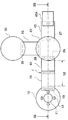
- 3A and 3B are a plan view and a cross-sectional view of a part of the imaging unit 2 before being housed in the housing 5.
- the housing 5 includes a cylindrical main body portion 5A and substantially hemispherical end cover portions 5B and 5C at both ends of the main body portion 5A.
- the end cover portion 5B is made of a transparent material, and the main body portion 5A and the end cover portion 5C are made of an integral opaque material.
- the elongated casing 5 has a rotationally symmetric shape with the central axis O in the longitudinal direction as a rotationally symmetric axis.
- the length L of the casing 5, that is, the length in the direction of the central axis O is 25 mm to 35 mm
- the diameter D5 in the orthogonal direction of the central axis O is 5 mm to 15 mm.
- the imaging unit 2 housed inside the housing 5 has a first substrate 10, a second substrate 20, a third substrate 30, a battery 40, and a substantially circular shape in plan view. 50 and the fourth substrate 60.
- the imaging device 11 and the light emitting device 12 are mounted on the first substrate 10.
- a front in-vivo image illuminated by the light emitting element 12 is acquired by the imaging element 11.
- the first substrate 10 has a plurality of external electrodes 19 that are electrically connected to the imaging element 11 or the light emitting element 12.
- the second substrate 20 is a circuit board on which an electronic component 21 such as a CPU that controls the imaging unit 2 is mounted.
- the second substrate 20 has a plurality of connection electrodes 27, 28, and 29 that are electrically connected to the electronic component 21.
- the batteries 40 and 50 are button type batteries that supply driving power.
- the third substrate 30 has a connection electrode 39 and is a transmission substrate on which electronic components for wirelessly transmitting image data are mounted.
- the fourth substrate 60 is a power supply substrate on which electronic components that convert electric power from the batteries 40 and 50 into drive signals are mounted, and includes connection electrodes 69.
- the external electrode 19 of the first substrate 10, the connection electrodes 27, 28, 29 of the second substrate 20, and the connection electrode 39 of the third substrate have substantially the same configuration.
- various electronic components such as a chip capacitor, a diode, a chip resistor, and a chip inductor may be mounted on each substrate.
- the substrate of the imaging unit 2 is not limited to the substrate described above.
- an illumination board on which a light emitting element is mounted and an imaging board on which an imaging element is mounted may be used.
- the imaging substrate is regarded as the first substrate.
- the number of batteries may be one, or a spacer for adjusting the arrangement position may be provided.
- the first substrate 10, the second substrate 20, the third substrate 30, the batteries 40, 50, and the fourth substrate 60 are arranged such that their main surfaces are parallel and their centers are along the central axis O. In this state, it is housed inside the housing 5.
- the first substrate 10 is electrically connected to the flexible first relay wiring board 70.
- “electrically connected” is simply referred to as “connected”.
- the second substrate 20 is connected to the flexible second relay wiring board 80, the third relay wiring board 35, and the fourth relay wiring board 45.
- the fourth substrate 60 is connected to the flexible fifth relay wiring board 55.
- the outer diameter D40 of the batteries 40, 50 is larger than the outer diameters of the first substrate 10, the second substrate 20, the third substrate 30, and the fourth substrate 60. Further, as will be described later, the first relay wiring board 70, the second relay wiring board 80, and the like are also arranged in a space that extends the outer periphery of the battery 40 in the central axis direction. That is, the outer diameter D40 of the batteries 40 and 50 is the maximum outer diameter of the imaging unit 2.
- the first board 10, the first relay wiring board 70, the second relay wiring board 80, the second board 20, and the fourth relay wiring board 45 are arranged in a straight line. It is connected with.
- a conductor plate 45A serving as a contact point with the battery 40 is connected to the fourth relay wiring board 45.
- the third substrate 30 is connected to the second substrate 20 via a third relay wiring board 35 connected in a state of being arranged in a direction orthogonal to the second relay wiring board 80.
- a conductor plate 55 ⁇ / b> A serving as a contact point with the battery 50 is also connected to the fifth relay wiring board 55 connected to the fourth substrate 60.
- the first relay wiring board 70 includes a flexible substrate 71, an adhesive layer 72 disposed on the entire surface of one surface of the substrate 71, and a plurality of layers disposed on the adhesive layer 72.
- the wiring 73 includes a first electrode pad 73A, a wiring part 73B, and a third electrode pad 73C.
- the second relay wiring board 80 has substantially the same configuration as the first relay wiring board 70, and includes a substrate 81, an adhesive layer 82, a second electrode pad 83A, a wiring portion 83B, and a fourth electrode pad 83C. Wiring 83.
- the relay wiring boards 70 and 80 are further provided with adhesive layer patterns 74 and 84 for temporary fixing.
- adheresion refers to a state of “fixing” through an adhesive layer that has been cured and solidified.
- blunting refers to a state of “temporary fixing” through an adhesive layer containing a gel component and rich in flexibility. In “temporary fixing”, it can be peeled off or reattached. Further, “closely contact” means a state of surface contact.
- the first relay wiring board 70 and the second relay wiring board 80 are arranged such that the first electrode pad 73A and the second electrode pad 83A face each other.
- the first electrode pad 73A and the second electrode pad 83A are connected by being pressed and in close contact with each other.
- the first relay wiring board 70 and the second relay wiring board 80 are fixed by being bonded by the adhesive layers 72 and 82.
- the capsule endoscope 1 is strongly required to be miniaturized because of its minimal invasiveness.
- the distance D1 (see FIG. 2) between the first substrate 10 and the second substrate 20 is as narrow as 0.5 mm or more and 3 mm or less.
- the substantial length D2 (see FIG. 3A) of the first relay wiring board 70 and the second relay wiring board 80 that connect the first substrate 10 and the second substrate 20 takes into account variations during manufacturing. Thus, it is set longer than D1.
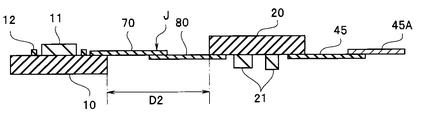
- the first electrode pad 73A and the second electrode pad 83A are flexible and are not joined using a non-flexible member such as solder. Therefore, as shown in FIG. 2, the connecting portion J between the first electrode pad 73A and the second electrode pad 83A can be bent and deformed in a concave state.
- D2 is preferably 110% or more and 200% or less of D1. If it is above the range, the first substrate 10 and the second substrate 20 can be arranged in parallel at a predetermined distance D1, and if it is below the range, the first substrate 10 and the second substrate 20 are deformed by bending. Can be inserted.
- the third relay wiring board 35, the fourth relay wiring board 45, and the fifth relay wiring board 55 are also partially bent and deformed into a concave state. Then, the batteries 40 and 50 are sandwiched between the conductor plate 45A connected to the fourth relay wiring board 45 and the conductor plate 55A connected to the fifth relay wiring board 55.
- the first relay wiring board 70 and the second relay wiring board 80 are curved and deformed so that the outer circumferences of the batteries 40 and 50 are disposed in a space extending in the central axis direction.
- the third relay wiring board 35, the fourth relay wiring board 45, and the fifth relay wiring board 55 are also arranged in a space that extends the outer periphery of the batteries 40, 50 in the central axis direction. For this reason, the imaging unit 2 has a small diameter.
- the first relay wiring board 70 and the second relay wiring board 80 are temporarily fixed via the adhesive layer patterns 74 and 84, and the operation is confirmed, and then the adhesive layers 72 and 82 are used. Is fixed. For this reason, when there is an abnormality in either the first substrate 10 or the second substrate 20, only the substrate having the abnormality can be replaced.
- the imaging unit 2 and the endoscope 1 have a small diameter and high productivity.
- the third relay wiring board 35, the fourth relay wiring board 45, and the fifth relay wiring board 55 are composed of two relay wiring boards having a similar configuration to the first relay wiring board 70 and the second relay wiring board 80. May be.
- Step S11> Fabrication of first substrate, fabrication of second substrate Imaging of CCD or CMOS image sensor or the like on stud bump of first substrate 10 made of a substantially circular inflexible base material such as glass epoxy resin.
- An element 11 and a light emitting element 12 such as an LED are mounted. By mounting, the image sensor 11 and the light emitting element 12 are connected to the respective external electrodes 19.
- the electronic component 21 is mounted on the substantially circular inflexible second substrate 20.
- the electronic component 21 is connected to each connection electrode 29 by being mounted.
- Step S12 Production of First Relay Wiring Board and Production of Second Relay Wiring Board
- First relay wiring board 70 is produced and connected to first substrate 10
- second relay wiring board 80 is produced and connected to second substrate 20.
- each substrate may be a flexible substrate bonded to a non-flexible substrate.
- etc., Was mounted may be adhere
- the external electrode 19 and the third electrode pad 73C may be fixed immediately without being temporarily fixed. As will be described later, ultraviolet irradiation is used for fixing.
- the third relay wiring board 35 is connected and fixed to the connection electrode 27 of the second substrate 20, and the fourth relay wiring board 45 is connected and fixed to the connection electrode 28.
- the fourth relay wiring board 55 is connected and fixed to the connection electrode 69 of the fourth substrate 60.
- connection in step S12 may be solder bonding, it is preferable to connect at a temperature of 250 ° C. or lower.
- the first wiring 73 of the first relay wiring board 70 has a third electrode pad 73C at one end, and the external electrode 19 of the first substrate 10 is electrically connected by being in close contact with the third electrode pad 73C.
- the second wiring 83 of the second relay wiring board 80 has a fourth electrode pad 83C at one end, and the connection electrode 27 of the second substrate 20 is in close contact with the fourth electrode pad 83C.
- it is preferably fixed by the adhesive layer 72 in an electrically connected state.
- the first relay wiring board 70 and the second relay wiring board 80 are arranged so that the first electrode pad 73A and the second electrode pad 83A face each other. Then, the first electrode pad 73A and the second electrode pad 83A are temporarily fixed via the adhesive layer patterns 74 and 84 in a state where they are connected by being pressed and in close contact. Note that, when temporarily fixed, the adhesive layers 72 and 82 are also in close contact, but since they are uncured, the influence of the adhesive layers 72 and 82 on the peel strength is very small and can be ignored.
- the thickness of the adhesive layer pattern 74 of the first relay wiring board 70 is preferably 10 ⁇ m or more and 500 ⁇ m or less.
- the pressure-sensitive adhesive layer pattern 74 is made of a gel-like pressure-sensitive adhesive having a gel fraction of 30% by weight to 70% by weight. The gel fraction is expressed as a percentage of the original mass by measuring the mass after drying the insoluble matter remaining after leaving the adhesive in toluene for 24 hours.
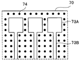
- the adhesive layer pattern 74 is disposed on the adhesive layer 72 around the wiring 73 as a dod pattern.
- the first relay wiring board 70 can be temporarily fixed by the adhesive layer pattern 74. That is, the peel strength (180 degree peel test ISO 29862 2007) of the second relay wiring board 80 attached through the adhesive layer patterns 74 and 84 is, for example, 0.05 N / 10 mm or less, and can be easily peeled off. It can also be reapplied. In contrast, the peel strength of the adhesive layer 72 after the curing treatment is, for example, 0.5 N / 10 mm or more.
- the adhesive layer pattern 74 of the relay wiring board 70 of Modification 1 shown in FIG. 7B is arranged in a frame shape only around the first electrode pad 73A.
- the patterned adhesive layer 72, adhesive layer pattern 74, and wiring 73 are each disposed on the substrate 71. That is, the adhesive layer 72 is not provided on the entire surface of the relay wiring board 70.
- the relay wiring board 70 is disposed on the relay wiring board 70 without the adhesive layer 72 interposed therebetween.
- the adhesive layer may have a function of an adhesive layer pattern having a small peel strength before the curing process. That is, the pressure-sensitive adhesive layer pattern may function as an adhesive layer having a high peel strength by the curing process. Further, the substrate 71 of the relay wiring board may have the function of the adhesive layer 72.
- the third relay wiring board 35 connected to the second substrate 20 is connected to the third substrate 30 and temporarily fixed.
- the conductor plate 45 ⁇ / b> A is connected to the fourth relay wiring board 45.
- the conductor plate 55 ⁇ / b> A is connected to the fifth relay wiring board 55 connected to the fourth substrate 60.
- any connection may be temporarily fixed through an adhesive layer pattern.
- the imaging unit 2 enters a driving state and performs a predetermined operation.
- the image sensor 11 captures an image in accordance with the light emission timing of the light emitting element 12, and the image data is wirelessly transmitted.
- step 15 When the image data is normally received by the receiving device arranged in the vicinity (S14: YES), the process of step 15 is performed. If reception is not possible (S14: NO), there is a problem with any component or connection, so the process returns to any one of steps S11 to S13 and the operation check inspection is performed again.
- the manufacturing method of the capsule endoscope 1 and the manufacturing method of the imaging unit 2 are less wasteful even if some of the members are defective, and the manufacturing cost can be greatly reduced. high.
- the adhesive layers 72 and 82 are cured, and the first relay wiring board 70 and the second relay wiring board 80 are fixed.
- the curing process is selected according to the material of the adhesive layer. For example, active energy rays such as ultraviolet rays that pass through the substrate 71 are irradiated, or a heat treatment at 250 ° C. or lower is performed.
- Step S16> Deformation to a Predetermined Form
- the first substrate 10, the second substrate 20, the third substrate 30, and the conductor plate 45A have their main surfaces parallel to each other and their centers along the central axis O. Placed in. That is, the connecting portion J of the connected first relay wiring board 70 and second relay wiring board 80, the third relay wiring board 35, and the fourth relay wiring board 45 are bent.
- the main surface of the conductor plate 55A connected to the fourth substrate 60 and the main surface of the fourth substrate 60 are arranged in parallel. That is, the fifth relay wiring board 55 is bent.
- the batteries 40 and 50 are sandwiched between the conductor plate 45A connected to the fourth relay wiring board 45 and the conductor plate 55A connected to the fifth relay wiring board 55.
- connection portion J of the first relay wiring board 70 and the second relay wiring board 80 that is, the first electrode pad 73A fixed in close contact with the first electrode pad 73A.
- the two-electrode pad 83 ⁇ / b> A is bent and deformed in a concave state and is inserted between the first substrate 10 and the second substrate 20.
- the 1st relay wiring board 70 and the 2nd relay wiring board 80 are also arrange
- the capsule endoscope manufacturing method and the imaging unit manufacturing method of the embodiment have high productivity.
- the capsule endoscope 1 is described as an example.
- the capsule endoscope 1 may be a capsule medical device for collecting digestive juice, a swallowing pH sensor, or various capsule medical devices such as a drug delivery system. Has the same effect.
- the imaging unit 2A of the second embodiment will be described. Since the imaging unit 2A is similar to the imaging unit 2, components having the same function are denoted by the same reference numerals and description thereof is omitted.
- connection portion JA is similar to the configuration of the connection portion J of the imaging unit 2. Note that no adhesive layer or the like is shown in FIG.
- the imaging unit 2A includes a glass lid 18, an imaging element 10A corresponding to a first substrate, a flexible substrate 70A that is a first relay wiring board, and a flexible substrate 80A that is a second relay wiring board.
- a glass lid 18 is bonded to the light receiving portion 11A formed on the imaging element 10A via an adhesive resin.
- a glass lid 18 made of transparent glass protects the light receiving portion 11A.
- the external electrode 19 connected to the image sensor 10A is a bonding pad provided with stud bumps.
- One end of the first wiring 73 of the flexible substrate 70A constitutes an inner lead 75, and the other end has a first electrode pad 73C.
- the second wiring 83 of the flexible substrate 80A has a second electrode pad 83C at one end.
- the flexible board 70A and the flexible board 80A have the same configuration as the first relay wiring board 70 and the like. For this reason, the flexible substrate 70A can be fixed after being connected to the flexible substrate 80A and temporarily fixed.
- the electrode pads of the flexible substrate can be connected and temporarily fixed. For this reason, even if a failure occurs in any of the members, it is only necessary to replace the defective member, so that the cost can be greatly reduced.
- the portion exposed on the surface of the first wiring 73 of the flexible substrate 70B is connected to the external electrode 19.
- the imaging unit 2B has the same effect as the imaging unit 2A. That is, since the first electrode pad 73A and the second electrode pad 83A that are fixed in close contact and electrically connected are curved and deformed, they have a small diameter.
Landscapes
- Life Sciences & Earth Sciences (AREA)
- Health & Medical Sciences (AREA)
- Surgery (AREA)
- Engineering & Computer Science (AREA)
- Physics & Mathematics (AREA)
- Optics & Photonics (AREA)
- Radiology & Medical Imaging (AREA)
- Heart & Thoracic Surgery (AREA)
- Veterinary Medicine (AREA)
- Biophysics (AREA)
- Nuclear Medicine, Radiotherapy & Molecular Imaging (AREA)
- Pathology (AREA)
- Public Health (AREA)
- General Health & Medical Sciences (AREA)
- Biomedical Technology (AREA)
- Animal Behavior & Ethology (AREA)
- Medical Informatics (AREA)
- Molecular Biology (AREA)
- Multimedia (AREA)
- Manufacturing & Machinery (AREA)
- General Physics & Mathematics (AREA)
- Astronomy & Astrophysics (AREA)
- Signal Processing (AREA)
- Endoscopes (AREA)
- Instruments For Viewing The Inside Of Hollow Bodies (AREA)
Abstract
撮像ユニット2は、撮像素子11が実装された第1基板10と、一端が第1基板10と電気的に接続され他端に第1電極パッド73Aを有する第1配線73を含む第1中継配線板70と、電子部品21が実装された第2基板20と、一端が第2基板20と電気的に接続され他端に第2電極パッド83Aを有する第2配線83を含む第2中継配線板80と、を具備し、密着することで電気的に接続した状態で固定されている第1電極パッド73Aと第2電極パッド83Aとが湾曲変形している。
Description
本発明は、撮像素子が実装された第1基板と電子部品が実装された第2基板とを、第1中継配線板および第2中継配線板を介して電気的に接続している撮像ユニット、前記撮像ユニットを具備するカプセル型内視鏡、および前記カプセル型内視鏡の製造方法に関する。
撮像機能と無線送信機能とを具備するカプセル型内視鏡が普及段階にある。カプセル型内視鏡は、被検者に飲み込まれた後、自然排出されるまでの間、胃、小腸などの消化管の内部を蠕動運動に伴って移動し、撮像機能を用いて臓器の内部を撮像する。
消化管内を移動する間にカプセル型内視鏡によって撮像された画像は無線送信機能により画像信号として、被検体の外部に設けられた外部装置に送信され、そのメモリに記憶される。被検者は、無線受信機能とメモリ機能とを具備する外部装置を携帯することにより、カプセル型内視鏡を飲み込んだ後、自由に行動できる。カプセル型内視鏡による観察後は、外部装置のメモリに記憶された画像をディスプレイなどに表示させて診断等が行われる。ここで、低侵襲化のために、カプセル型内視鏡の小型化(短小化および細径化)は重要な課題である。
日本国特開2013-48826号公報には、複数の略円形の基板部がフレキシブル基板部を介して連接された配線板を含む撮像ユニットを、筐体内に収容したカプセル型内視鏡が開示されている。
しかし、この配線板では複数の基板部は連接され一体であるため、いずれか1つの基板部だけに異常があった場合であっても、その配線板を用いることができなかった。
日本国特開2004-14235号公報には、導体と導体とを密着し電気的に接続した状態で仮固定した後に、固定できる接続部材が開示されている。この接続部材を用いた撮像ユニットは、仮固定状態で動作確認を行うことで、異常があった基板部だけを交換して配線板を用いることができるため、生産性に優れている。
しかし、この接続部材を用いた場合には撮像ユニットの外径が大きくなってしまうという問題があった。
本発明は、生産が高く細径の撮像ユニット、前記撮像ユニットを具備するカプセル型内視鏡、および前記カプセル型内視鏡の製造方法に関する。
本発明の実施形態の撮像ユニットは、撮像素子が実装された第1基板と、一端が前記第1基板と電気的に接続され他端に第1電極パッドを有する第1配線、を含む第1中継配線板と、電子部品が実装された第2基板と、一端が前記第2基板と電気的に接続され他端に第2電極パッドを有する第2配線、を含む第2中継配線板と、を具備し、密着することで電気的に接続した状態で固定されている前記第1電極パッドと前記第2電極パッドとが湾曲変形している。
また、別の実施形態のカプセル型内視鏡は、撮像素子が実装され、前記撮像素子と電気的に接続されている外部電極を有する第1基板と、一端が前記外部電極と電気的に接続され他端に第1電極パッドを有する第1配線、を含む可撓性の第1中継配線板と、電子部品が実装され、前記電子部品と電気的に接続されている接続電極を有する第2基板と、一端が前記接続電極と電気的に接続され、前記第1電極パッドと密着することで電気的に接続した状態で固定されている第2電極パッドを他端に有する第2配線、を含む可撓性の第2中継配線板と、前記第1基板と前記第2基板と前記第1中継配線板と前記第2中継配線板とが収容されている、長手方向の中心軸を回転対称軸とする回転対称形状のカプセルである筐体と、を具備し、前記第1基板の主面と前記第2基板の主面とが平行に配置されており、前記第1電極パッドおよび第2電極パッドが湾曲変形し、前記第1基板と前記第2基板との間に挿入されている。
さらに、別の実施形態のカプセル型内視鏡の製造方法は、第1基板と第2基板と第1中継配線板と第2中継配線板とを有する撮像ユニットが筐体に収容されており、前記第1基板と前記第2基板とが、前記第1中継配線板および前記第2中継配線板を介して電気的に接続されている、カプセル型内視鏡の製造方法であって、外部電極を有する前記第1基板に撮像素子を実装し、前記撮像素子と前記外部電極とを電気的に接続する工程と、接続電極を有する前記第2基板に電子部品を実装し、前記電子部品と前記接続電極とを電気的に接続する工程と、一端が前記外部電極と電気的に接続され他端に第1電極パッドを有する第1配線、を含む第1中継配線板と、一端が前記接続電極と電気的に接続され他端に第2電極パッドを有する第2配線、を含む第2中継配線板と、を作製する工程と。前記第1電極パッドと前記第2電極パッドとを密着することで電気的に接続した状態で、前記第1電極パッドの周囲の粘着層パターンにより仮固定する工程と、前記第2基板を介して前記撮像素子に駆動電力を供給し動作を確認する工程と、前記第1電極パッドの周囲の接着層を硬化し前記第1電極パッドと前記第2電極パッドとを固定する工程と、前記第1基板の主面と前記第2基板の主面とを平行に配置する工程と、固定されている前記第1電極パッドと前記第1電極パッドとを湾曲変形し前記第1基板と前記第2基板との間に挿入する工程と、前記第1基板と前記第2基板と前記第1中継配線板と前記第2中継配線板とを含む撮像ユニットを前記筐体に収容する工程と、を具備する。
本発明によれば、生産が高い細径の撮像ユニット、前記撮像ユニットを具備するカプセル型内視鏡、および前記カプセル型内視鏡の製造方法を提供できる。
<第1実施形態>
図1および図2に示すように本実施形態のカプセル型内視鏡(以下「内視鏡」という)1は、カプセル型の筐体5に撮像ユニット2が収容されている。なお、図3Aおよび図3Bは筐体5に収容する前の撮像ユニット2の一部分の平面図および断面図である。
図1および図2に示すように本実施形態のカプセル型内視鏡(以下「内視鏡」という)1は、カプセル型の筐体5に撮像ユニット2が収容されている。なお、図3Aおよび図3Bは筐体5に収容する前の撮像ユニット2の一部分の平面図および断面図である。
以下の説明において、実施形態に基づく図面は、模式的なものであり、各部分の厚みと幅との関係、夫々の部分の厚みの比率などは現実のものとは異なることに留意すべきであり、図面の相互間においても互いの寸法の関係や比率が異なる部分が含まれている場合がある。また、一部の構成要素の図示を省略する場合がある。
筐体5は、円筒形の本体部5Aと、本体部5Aの両端の略半球状の端部カバー部5B、5Cとからなる。端部カバー部5Bは透明材料からなり、本体部5Aおよび端部カバー部5Cは一体の不透明材料からなる。
細長い筐体5は長手方向の中心軸Oを回転対称軸とする回転対称形状である。そして、例えば、筐体5の長さL、すなわち、中心軸Oの方向の長さは25mm~35mmであり、中心軸Oの直交方向の直径D5は、5mm~15mmである。
図2および図3Aに示すように、筐体5の内部に収容されている撮像ユニット2は、いずれも平面視略円形の第1基板10、第2基板20、第3基板30、電池40、50、および第4基板60を含む。
第1基板10には撮像素子11と発光素子12とが実装されている。発光素子12により照明された前方の体内画像は撮像素子11により取得される。第1基板10は撮像素子11または発光素子12と電気的に接続されている複数の外部電極19を有する。第2基板20は撮像ユニット2の制御等を行うCPU等の電子部品21が実装されている回路基板である。第2基板20は電子部品21と電気的に接続されている複数の接続電極27、28、29を有する。電池40、50は駆動電力を供給するボタン型電池である。
第3基板30は接続電極39を有する、画像データを無線送信する電子部品が実装された送信基板である。そして、第4基板60は、電池40、50からの電力を駆動信号に変換する電子部品が実装された電源基板であり、接続電極69を有する。なお、第1基板10の外部電極19と、第2基板20の接続電極27、28、29と第3基板の接続電極39とは略同じ構成である。なお、各基板には、既に説明した部品以外にも、各種の電子部品、例えば、チップコンデンサ、ダイオード、チップ抵抗、およびチップインダクタ等が実装されていてもよい。
また、撮像ユニット2の基板は、上記説明の基板に限られるものではない。例えば、第1基板10に替えて、発光素子が実装された照明基板と、撮像素子が実装された撮像基板とを用いてもよい。この場合には撮像基板を第1基板と見なす。また、電池は1個でも良いし、配置位置の調整のためのスペーサーを有していてもよい。
そして、第1基板10、第2基板20、第3基板30、電池40、50、および第4基板60は、それぞれの主面が平行に、かつ、それぞれの中心が中心軸Oに沿って配置された状態で、筐体5の内部に収容されている。
第1基板10は、可撓性の第1中継配線板70と電気的に接続されている。なお、以下、「電気的に接続されている」を、単に「接続されている」という。
第2基板20は、いずれも可撓性の第2中継配線板80、第3中継配線板35、および第4中継配線板45と接続されている。第4基板60は、可撓性の第5中継配線板55と接続されている。
電池40、50の外径D40は、第1基板10、第2基板20、第3基板30、および第4基板60の外径よりも大きい。さらに後述するように、第1中継配線板70および第2中継配線板80等も電池40の外周を中心軸方向に延長した空間内に、配置されている。すなわち、電池40、50の外径D40が、撮像ユニット2の最大外径となっている。
図3Aおよび図3Bに示すように、第1基板10、第1中継配線板70、第2中継配線板80、第2基板20、および第4中継配線板45は、直線上に配置された状態で連接されている。さらに、第4中継配線板45には電池40との接点となる導体板45Aが接続されている。第3基板30は、第2中継配線板80と直交する方向に配置された状態で連接された第3中継配線板35を介して第2基板20と接続されている。また、第4基板60と接続されている第5中継配線板55にも電池50との接点となる導体板55Aが接続されている。
以下、第1中継配線板70と第2中継配線板80との接続について詳細に説明する。
以下、第1中継配線板70と第2中継配線板80との接続について詳細に説明する。
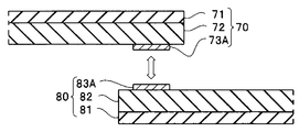
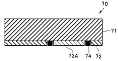
図4に示すように、第1中継配線板70は、可撓性の基板71と、基板71の片面の全面に配設された接着層72と、接着層72の上に配設された複数の配線73と、を含む。配線73は、第1電極パッド73Aと配線部73Bと第3電極パッド73Cを有する。なお、第2中継配線板80は第1中継配線板70と、略同じ構成であり、基板81、接着層82、第2電極パッド83Aと配線部83Bと第4電極パッド83Cとを有する第2配線83と、を含む。中継配線板70、80には、さらに仮固定のための粘着層パターン74、84が配設されている。
なお、本明細書において、「接着(adhere)」とは、硬化し固体となった接着層を介して「固定(fixing)」されている状態をいう。これに対して「粘着(stick)」とは、ゲル成分を含み柔軟性に富んだ粘着層を介して「仮固定(temporary fixing)」されている状態をいう。「仮固定」では、剥離したり再貼付したりできる。また「密着(closely contact)」とは、面接触している状態をいう。
図5Aに示すように、第1中継配線板70と第2中継配線板80とは、第1電極パッド73Aと第2電極パッド83Aとが対向するように配置される。そして、図5Bに示すように、第1電極パッド73Aと第2電極パッド83Aとは押圧し密着することで接続されている。そして、第1中継配線板70と第2中継配線板80とは、接着層72、82により接着されることで固定されている。
次に、筐体5の内部に収容するために、連接された第1基板10、第2基板20および第3基板30の主面が平行になるように配置される。カプセル型内視鏡1は低侵襲化のため小型化が強く求められている。長さを短くするために、例えば、第1基板10と第2基板20との間隔D1(図2参照)は0.5mm以上3mm以下と狭い。これに対して第1基板10と第2基板20とを接続している第1中継配線板70および第2中継配線板80の実質長D2(図3A参照)は、製造時のバラツキを考慮して、D1より長く設定されている。
しかし、第1電極パッド73Aと第2電極パッド83Aとは可撓性であり、かつ、半田等の非可撓性部材を用いて接合されていない。このため、図2に示したように、第1電極パッド73Aと第2電極パッド83Aとの接続部Jは、凹状態に湾曲変形することができる。
D2はD1の110%以上200%以下であることが好ましい。前記範囲以上であれば第1基板10と第2基板20とを所定間隔D1で平行に配置可能で、前記範囲以下であれば湾曲変形することで第1基板10と第2基板20との間に挿入可能である。
なお、第3中継配線板35、第4中継配線板45および第5中継配線板55も、一部が折り曲げられ凹状態に湾曲変形している。そして、第4中継配線板45と接続した導体板45Aと第5中継配線板55と接続した導体板55Aとによりに電池40、50が挟持される。
第1中継配線板70と第2中継配線板80とは湾曲変形することで、電池40、50の外周を中心軸方向に延長した空間内に配置されている。また第3中継配線板35、第4中継配線板45および第5中継配線板55も電池40、50の外周を中心軸方向に延長した空間内に配置されている。このため、撮像ユニット2は、細径である。
なお、後述するように、第1中継配線板70と第2中継配線板80とは粘着層パターン74、84を介して仮固定され、動作確認が行われた後に、接着層72、82を介して固定されている。このため、第1基板10または第2基板20のいずれかに異常があった場合には、異常のあった基板だけを交換することができる。
このため、撮像ユニット2および内視鏡1は、細径で、かつ生産性が高い。
なお、第3中継配線板35、第4中継配線板45および第5中継配線板55が、第1中継配線板70および第2中継配線板80と類似構成の2つの中継配線板から構成されていてもよい。
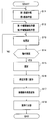
次に、図6のフローチャートに沿って、実施形態のカプセル型内視鏡および撮像ユニットの製造方法について説明する。
<ステップS11>第1基板作製、第2基板作製
略円形の非可撓性の、例えばガラスエポキシ樹脂を基材とする第1基板10のスタッドバンプ等に、CCD、またはCMOSイメージセンサ等の撮像素子11と、LED等の発光素子12とが実装される。実装されることで、撮像素子11と発光素子12とは、それぞれの外部電極19と接続される。
略円形の非可撓性の、例えばガラスエポキシ樹脂を基材とする第1基板10のスタッドバンプ等に、CCD、またはCMOSイメージセンサ等の撮像素子11と、LED等の発光素子12とが実装される。実装されることで、撮像素子11と発光素子12とは、それぞれの外部電極19と接続される。
また、略円形の非可撓性の第2基板20に、電子部品21が実装される。そして、実装されることで、電子部品21は、それぞれの接続電極29と接続される。
<ステップS12>第1中継配線板作製、第2中継配線板作製
第1中継配線板70が作製され第1基板10と接続され、第2中継配線板80が作製され第2基板20と接続される。
第1中継配線板70が作製され第1基板10と接続され、第2中継配線板80が作製され第2基板20と接続される。
そして、第1基板10の外部電極19に第1中継配線板70の第3電極パッド73Cが接続される。なお、各基板は可撓性基板が、非可撓性基板に接着されていてもよい。例えば、第1基板10は撮像素子11等が実装されたポリイミド基板が、非可撓性基板に接着されていてもよい。また、外部電極19と第3電極パッド73Cとは仮固定しないで直ちに固定されてもよい。後述するように、固定には紫外線照射が用いられる。
さらに、第2基板20の接続電極27には第3中継配線板35が接続され固定され、接続電極28には第4中継配線板45が接続され固定される。
なお、別途、第3基板30および第4基板60も作製される。第4基板60の接続電極69には、第4中継配線板55が接続され固定される。
なお、ステップS12における接続は半田接合でもよいが、250℃以下の温度で接続することが好ましい。
例えば、第1中継配線板70の第1配線73が一端に第3電極パッド73Cを有し、第1基板10の前記外部電極19が第3電極パッド73Cと密着することで電気的に接続した状態で接着層72により固定されており、第2中継配線板80の第2配線83が一端に第4電極パッド83Cを有し第2基板20の前記接続電極27が第4電極パッド83Cと密着することで電気的に接続した状態で接着層72により固定されていることが好ましい。
<ステップS13>仮固定
図5Aに示したように、第1中継配線板70と第2中継配線板80とが第1電極パッド73Aと第2電極パッド83Aとが対向するように配置される。そして、第1電極パッド73Aと第2電極パッド83Aとは押圧され密着することで接続した状態で、粘着層パターン74、84を介して仮固定される。なお、仮固定されると接着層72、82も密着するが、未硬化であるため、接着層72、82による剥離強度への影響は非常に小さく無視できる。
図5Aに示したように、第1中継配線板70と第2中継配線板80とが第1電極パッド73Aと第2電極パッド83Aとが対向するように配置される。そして、第1電極パッド73Aと第2電極パッド83Aとは押圧され密着することで接続した状態で、粘着層パターン74、84を介して仮固定される。なお、仮固定されると接着層72、82も密着するが、未硬化であるため、接着層72、82による剥離強度への影響は非常に小さく無視できる。
なお、第1中継配線板70の粘着層パターン74の厚さは10μm以上500μm以下が好ましい。例えば、粘着層パターン74は、ゲル分率が30重量%以上70重量%以下のゲル状の粘着剤からなる。ゲル分率は、粘着剤をトルエン中に浸漬し、24時間放置後に残った不溶分の乾燥後の質量を測定し、元の質量に対する百分率で表す。
図7Aに示すように粘着層パターン74は、配線73の周囲の接着層72の上にドッドパターンとして配設されている。第1中継配線板70は粘着層パターン74により仮固定することができる。すなわち、粘着層パターン74、84を介して貼付された第2中継配線板80の剥離強度(180度剥離試験 ISO29862 2007)は、例えば、0.05N/10mm以下であり、容易に剥離可能で、また再貼付も可能である。なお、これに対して硬化処理後の接着層72の剥離強度は、例えば、0.5N/10mm以上である。
一方、図7Bに示す変形例1の中継配線板70の粘着層パターン74は、第1電極パッド73Aの周囲にだけ額縁状に配置されている。また、図7Cに示す変形例2の中継配線板70では、パターニングされている接着層72、粘着層パターン74および配線73は、それぞれが基板71の上に配設されている。すなわち、接着層72は中継配線板70の全面に配設されていない。また、中継配線板70は接着層72を介さないで中継配線板70に配設されている。
また、図示しないが、中継配線板では、接着層が硬化処理前に剥離強度の小さい粘着層パターンの機能を有していてもよい。すなわち、粘着層パターンが硬化処理により剥離強度が大きい接着層として機能してもよい。さらに、中継配線板の基板71が接着層72の機能を有していてもよい。
さらに、第2基板20と接続されている第3中継配線板35が、第3基板30と接続され仮固定される。また、第4中継配線板45に導体板45Aが接続される。また、第4基板60と接続されている第5中継配線板55に導体板55Aが接続される。もちろん、いずれの接続も粘着層パターンを介しての仮固定であってもよい。
<ステップS14>動作確認
仮固定された状態で、第4中継配線板45と接続された導体板45Aと第5中継配線板55と接続された導体板55Aとの間に、電池40、50と同じ電圧の直流電圧が印加される。すると、撮像ユニット2は駆動状態となり所定の動作を行う。例えば、発光素子12の発光タイミングに合わせて撮像素子11が画像を撮像し、画像データが無線送信される。
仮固定された状態で、第4中継配線板45と接続された導体板45Aと第5中継配線板55と接続された導体板55Aとの間に、電池40、50と同じ電圧の直流電圧が印加される。すると、撮像ユニット2は駆動状態となり所定の動作を行う。例えば、発光素子12の発光タイミングに合わせて撮像素子11が画像を撮像し、画像データが無線送信される。
近傍に配置した受信装置に画像データが正常に受信された場合には(S14:YES)には、ステップ15の処理が行われる。受信できなかった場合には(S14:NO)には、いずれかの構成要素または接続に問題があるため、S11~S13のいずれかの工程に戻り、再度、動作確認検査が行われる。
本製造方法では、第1中継配線板70と第2中継配線板80とは仮固定されているので、容易に剥離できる。また、例えば、第1中継配線板70が接続された第1基板10を、別の第1中継配線板が接続された第1基板と交換することができる。このため、カプセル型内視鏡1の製造方法、および撮像ユニット2の製造方法は一部の部材が不良であっても無駄が少なく、製造コストを大幅に低減することができるため、生産性が高い。
<ステップS15>固定(硬化)
接着層72、82の硬化処理が行われ、第1中継配線板70と第2中継配線板80とが固定される。硬化処理は接着層の材料に応じて選択されるが、例えば、基板71を透過する紫外線等の活性エネルギー線が照射されたり、250℃以下の熱処理が行われたりする。
接着層72、82の硬化処理が行われ、第1中継配線板70と第2中継配線板80とが固定される。硬化処理は接着層の材料に応じて選択されるが、例えば、基板71を透過する紫外線等の活性エネルギー線が照射されたり、250℃以下の熱処理が行われたりする。
<ステップS16>所定の形態に変形
第1基板10、第2基板20、第3基板30、および導体板45Aは、それぞれの主面が平行に、かつ、それぞれの中心が中心軸Oに沿うように配置される。すなわち、接続された第1中継配線板70および第2中継配線板80の接続部Jと、第3中継配線板35と、第4中継配線板45とが折り曲げられる。
第1基板10、第2基板20、第3基板30、および導体板45Aは、それぞれの主面が平行に、かつ、それぞれの中心が中心軸Oに沿うように配置される。すなわち、接続された第1中継配線板70および第2中継配線板80の接続部Jと、第3中継配線板35と、第4中継配線板45とが折り曲げられる。
別途、第4基板60と接続された導体板55Aの主面と第4基板60の主面とが平行になるように配置される。すなわち、第5中継配線板55が折り曲げられる。
そして、第4中継配線板45と接続された導体板45Aと第5中継配線板55と接続された導体板55Aとによりに電池40、50が挟持される。
<ステップS17>接続部の湾曲変形
図8に示すように、第1中継配線板70と第2中継配線板80の接続部J、すなわち、密着状態で固定されている第1電極パッド73Aと第2電極パッド83Aとが、凹状態に湾曲変形されて、第1基板10と第2基板20との間に挿入される。このため、第1中継配線板70および第2中継配線板80も電池40、50の外周を中心軸方向に延長した空間内に、配置される。
図8に示すように、第1中継配線板70と第2中継配線板80の接続部J、すなわち、密着状態で固定されている第1電極パッド73Aと第2電極パッド83Aとが、凹状態に湾曲変形されて、第1基板10と第2基板20との間に挿入される。このため、第1中継配線板70および第2中継配線板80も電池40、50の外周を中心軸方向に延長した空間内に、配置される。
<ステップS18>筐体に収容
撮像ユニット2が筐体5の内部に収容される。すなわち、筐体5の内径D5は、撮像ユニット2の最大外径D40より僅かに大きい程度である。このためカプセル型内視鏡1は細径である。
撮像ユニット2が筐体5の内部に収容される。すなわち、筐体5の内径D5は、撮像ユニット2の最大外径D40より僅かに大きい程度である。このためカプセル型内視鏡1は細径である。
以上の説明のように、実施形態のカプセル型内視鏡の製造方法および撮像ユニットの製造方法は生産性が高い。
なお、上記説明は、カプセル型内視鏡1を例に説明したが、消化液採取用カプセル型医療機器、嚥下型のpHセンサ、またはドラッグデリバリーシステムのような各種カプセル型医療機器であっても同様の効果を有する。
<第2実施形態>
次に第2実施形態の撮像ユニット2Aについて説明する。撮像ユニット2Aは撮像ユニット2と類似しているので、同じ機能の構成要素には同じ符号を付し説明は省略する。
次に第2実施形態の撮像ユニット2Aについて説明する。撮像ユニット2Aは撮像ユニット2と類似しているので、同じ機能の構成要素には同じ符号を付し説明は省略する。
すなわち図9に示すように、接続部JAの構成は、撮像ユニット2の接続部Jの構成と類似している、なお、図9では接着層等は表示していない。
図9に示すように撮像ユニット2Aは、ガラスリッド18と、第1基板に相当する撮像素子10Aと、第1中継配線板であるフレキシブル基板70Aと、第2中継配線板であるフレキシブル基板80Aと、を具備する。撮像素子10Aに形成された受光部11Aには、接着樹脂を介してガラスリッド18が接着されている。透明ガラスからなるガラスリッド18は受光部11Aを保護する。撮像素子10Aと接続された外部電極19は、スタッドバンプが配設されたボンディングパッドである。
フレキシブル基板70Aの第1配線73は、一端がインナーリード75を構成しており、他端に第1電極パッド73Cを有する。フレキシブル基板80Aの第2配線83は、一端に第2電極パッド83Cを有する。
フレキシブル基板70Aおよびフレキシブル基板80Aは、第1中継配線板70等と同じ構成を有する。このため、フレキシブル基板70Aはフレキシブル基板80Aと接続し仮固定した後に固定することができる。
撮像ユニット2Aの製造方法では、フレキシブル基板70A、80Aに図示しない電子部品を実装した後に、フレキシブル基板の電極パッドを接続し仮固定できる。このため、いずれかの部材に不具合が生じたとしても不良部材のみを交換しれば良いため、コストを大幅に低減することができる。
さらに、フレキシブル基板を接続するときに、高温処理したり大荷重を加えたりすることがないため、各基板に搭載された部品や撮像素子へのダメージを抑えることができる。
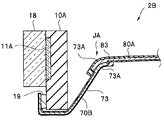
なお、図10にした第2実施形態の変形例の撮像ユニット2Bでは、フレキシブル基板70Bの第1配線73の表面に露出した部分が外部電極19と接続されている。
撮像ユニット2Bは、撮像ユニット2Aと同じ効果を有する。すなわち、密着することで電気的に接続した状態で固定されている第1電極パッド73Aと第2電極パッド83Aとが湾曲変形しているため、細径である。
本発明は、上述した実施形態等に限定されるものではなく、本発明の要旨を変えない範囲において、種々の変更、改変等ができる。
本出願は、2014年7月16日に日本国に出願された特願2014-146197号を優先権主張の基礎として出願するものであり、上記の開示内容は、本願明細書、請求の範囲、図面に引用されたものとする。
Claims (8)
- 撮像素子が実装された第1基板と、
一端が前記第1基板と電気的に接続され他端に第1電極パッドを有する第1配線、を含む第1中継配線板と、
電子部品が実装された第2基板と、
一端が前記第2基板と電気的に接続され他端に第2電極パッドを有する第2配線、を含む第2中継配線板と、を具備し、
密着することで電気的に接続した状態で固定されている前記第1電極パッドと前記第2電極パッドとが湾曲変形していることを特徴とする撮像ユニット。 - 前記第1中継配線板および前記第2中継配線板のそれぞれが、仮固定のための粘着層パターンと、固定のための接着層と、を有することを特徴とする請求項1に記載の撮像ユニット。
- カプセル型内視鏡の筐体に収容されていることを特徴とする請求項1または請求項2に記載の撮像ユニット。
- 撮像素子が実装され、前記撮像素子と電気的に接続されている外部電極を有する第1基板と、
一端が前記外部電極と電気的に接続され他端に第1電極パッドを有する第1配線、を含む可撓性の第1中継配線板と、
電子部品が実装され、前記電子部品と電気的に接続されている接続電極を有する第2基板と、
一端が前記接続電極と電気的に接続され、前記第1電極パッドと密着することで電気的に接続した状態で固定されている第2電極パッドを他端に有する第2配線、を含む可撓性の第2中継配線板と、
前記第1基板と前記第2基板と前記第1中継配線板と前記第2中継配線板とが収容されている、長手方向の中心軸を回転対称軸とする回転対称形状のカプセルである筐体と、を具備し、
前記第1基板の主面と前記第2基板の主面とが平行に配置されており、
前記第1電極パッドおよび第2電極パッドが湾曲変形し、前記第1基板と前記第2基板との間に挿入されていることを特徴とするカプセル型内視鏡。 - 前記第1中継配線板および前記第2中継配線板のそれぞれが、仮固定のための粘着層パターンと、固定のための接着層と、を有することを特徴とする請求項4に記載のカプセル型内視鏡。
- 主面が前記第1基板の前記主面と平行に配置されている電池を具備し、
前記電池の外周を前記中心軸方向に延長した空間内に、前記第1基板と前記第2基板と前記第1中継配線板と前記第2中継配線板とが配置されていることを特徴とする請求項5に記載のカプセル型内視鏡。 - 前記第1中継配線板の前記第1配線が、前記一端に第3電極パッドを有し、
前記第1基板の前記外部電極が、前記第3電極パッドと密着することで電気的に接続した状態で前記接着層により固定されており、
前記第2中継配線板の第2配線が、前記一端に第4電極パッドを有し
前記第2基板の前記接続電極が、前記第4電極パッドと密着することで電気的に接続した状態で前記接着層により固定されていることを特徴とする請求項6に記載のカプセル型内視鏡。 - 第1基板と第2基板と第1中継配線板と第2中継配線板とを有する撮像ユニットが筐体に収容されており、前記第1基板と前記第2基板とが、前記第1中継配線板および前記第2中継配線板を介して電気的に接続されている、カプセル型内視鏡の製造方法であって、
外部電極を有する前記第1基板に撮像素子を実装し、前記撮像素子と前記外部電極とを電気的に接続する工程と、
接続電極を有する前記第2基板に電子部品を実装し、前記電子部品と前記接続電極とを電気的に接続する工程と、
一端が前記外部電極と電気的に接続され他端に第1電極パッドを有する第1配線、を含む第1中継配線板と、一端が前記接続電極と電気的に接続され他端に第2電極パッドを有する第2配線、を含む第2中継配線板と、を作製する工程と、
前記第1電極パッドと前記第2電極パッドとを密着することで電気的に接続した状態で、前記第1電極パッドの周囲の粘着層パターンにより仮固定する工程と、
前記第2基板を介して前記撮像素子に駆動電力を供給し動作を確認する工程と、
前記第1電極パッドの周囲の接着層を硬化し前記第1電極パッドと前記第2電極パッドとを固定する工程と、
前記第1基板の主面と前記第2基板の主面とを平行に配置する工程と、
固定されている前記第1電極パッドと前記第1電極パッドとを湾曲変形し前記第1基板と前記第2基板との間に挿入する工程と、
前記第1基板と前記第2基板と前記第1中継配線板と前記第2中継配線板とを含む撮像ユニットを前記筐体に収容する工程と、を具備することを特徴とするカプセル型内視鏡の製造方法。
Priority Applications (3)
| Application Number | Priority Date | Filing Date | Title |
|---|---|---|---|
| DE112015003278.9T DE112015003278T5 (de) | 2014-07-16 | 2015-05-08 | Bildaufnahmeeinheit, kapselendoskop und herstellungsverfahren für ein kapselendoskop |
| CN201580038304.XA CN106488734A (zh) | 2014-07-16 | 2015-05-08 | 摄像单元、胶囊型内窥镜和胶囊型内窥镜的制造方法 |
| US15/402,583 US10514535B2 (en) | 2014-07-16 | 2017-01-10 | Image pickup unit, capsule endoscope, and manufacturing method of capsule endoscope |
Applications Claiming Priority (2)
| Application Number | Priority Date | Filing Date | Title |
|---|---|---|---|
| JP2014146197A JP6374249B2 (ja) | 2014-07-16 | 2014-07-16 | 撮像ユニット、および、カプセル型内視鏡 |
| JP2014-146197 | 2014-07-16 |
Related Child Applications (1)
| Application Number | Title | Priority Date | Filing Date |
|---|---|---|---|
| US15/402,583 Continuation US10514535B2 (en) | 2014-07-16 | 2017-01-10 | Image pickup unit, capsule endoscope, and manufacturing method of capsule endoscope |
Publications (1)
| Publication Number | Publication Date |
|---|---|
| WO2016009706A1 true WO2016009706A1 (ja) | 2016-01-21 |
Family
ID=55078210
Family Applications (1)
| Application Number | Title | Priority Date | Filing Date |
|---|---|---|---|
| PCT/JP2015/063308 Ceased WO2016009706A1 (ja) | 2014-07-16 | 2015-05-08 | 撮像ユニット、カプセル型内視鏡、およびカプセル型内視鏡の製造方法 |
Country Status (5)
| Country | Link |
|---|---|
| US (1) | US10514535B2 (ja) |
| JP (1) | JP6374249B2 (ja) |
| CN (1) | CN106488734A (ja) |
| DE (1) | DE112015003278T5 (ja) |
| WO (1) | WO2016009706A1 (ja) |
Families Citing this family (8)
| Publication number | Priority date | Publication date | Assignee | Title |
|---|---|---|---|---|
| JP6984168B2 (ja) * | 2017-05-17 | 2021-12-17 | セイコーエプソン株式会社 | 撮像装置および内視鏡 |
| JP6596551B1 (ja) | 2018-09-06 | 2019-10-23 | 株式会社フジクラ | 電子部品ユニット |
| US11945144B2 (en) * | 2019-09-06 | 2024-04-02 | Ambu A/S | Tip part assembly for an endoscope |
| JP7619023B2 (ja) * | 2020-11-27 | 2025-01-22 | セイコーエプソン株式会社 | 画像処理装置 |
| JP7571502B2 (ja) * | 2020-11-27 | 2024-10-23 | セイコーエプソン株式会社 | 画像処理装置 |
| JP7694019B2 (ja) * | 2020-11-27 | 2025-06-18 | セイコーエプソン株式会社 | 画像処理装置 |
| JP7622408B2 (ja) * | 2020-11-27 | 2025-01-28 | セイコーエプソン株式会社 | 画像処理装置 |
| JP7694020B2 (ja) * | 2020-11-27 | 2025-06-18 | セイコーエプソン株式会社 | 画像処理装置 |
Citations (3)
| Publication number | Priority date | Publication date | Assignee | Title |
|---|---|---|---|---|
| JP2004014235A (ja) * | 2002-06-05 | 2004-01-15 | Japan Aviation Electronics Industry Ltd | 電気接続部材、及びフィルム部材 |
| WO2008123464A1 (ja) * | 2007-03-30 | 2008-10-16 | Olympus Medical Systems Corp. | カプセル型医療装置およびカプセル型医療装置の製造方法 |
| JP2008307187A (ja) * | 2007-06-13 | 2008-12-25 | Olympus Medical Systems Corp | 体内画像取得装置、受信装置、および体内画像取得システム |
Family Cites Families (13)
| Publication number | Priority date | Publication date | Assignee | Title |
|---|---|---|---|---|
| JP2985640B2 (ja) * | 1994-02-10 | 1999-12-06 | 松下電器産業株式会社 | 電極接続体及びその製造方法 |
| JP4338280B2 (ja) * | 2000-02-15 | 2009-10-07 | Hoya株式会社 | カプセル内視鏡 |
| ATE546086T1 (de) * | 2001-06-18 | 2012-03-15 | Given Imaging Ltd | In-vivo-sensorvorrichtung mit einer leiterplatte aus starren und flexiblen abschnitten |
| DE10138278C1 (de) * | 2001-08-10 | 2003-04-03 | Infineon Technologies Ag | Elektronisches Bauteil mit aufeinander gestapelten elektronischen Bauelementen und Verfahren zur Herstellung derselben |
| JP4143304B2 (ja) * | 2002-01-24 | 2008-09-03 | 富士通株式会社 | カメラモジュールの製造方法 |
| JP2004179830A (ja) * | 2002-11-26 | 2004-06-24 | Miyota Kk | 小型カメラモジュール |
| US7014472B2 (en) * | 2003-01-13 | 2006-03-21 | Siliconpipe, Inc. | System for making high-speed connections to board-mounted modules |
| EP1707102B1 (en) * | 2004-01-19 | 2010-05-05 | Olympus Corporation | Capsule type medical treatment device |
| KR100885976B1 (ko) * | 2007-06-25 | 2009-03-03 | 삼성전자주식회사 | 인쇄회로기판, 이를 구비한 메모리 모듈 및 이의 제조방법 |
| JP2010187304A (ja) * | 2009-02-13 | 2010-08-26 | Panasonic Corp | 電子デバイス、その製造方法、これを用いた固体撮像装置およびその製造方法 |
| CN102238806A (zh) * | 2010-04-28 | 2011-11-09 | 富葵精密组件(深圳)有限公司 | 电路板模组 |
| JP5913870B2 (ja) * | 2011-08-31 | 2016-04-27 | オリンパス株式会社 | カプセル型医療装置 |
| US9704772B2 (en) * | 2014-04-02 | 2017-07-11 | Xintec Inc. | Chip package and method for forming the same |
-
2014
- 2014-07-16 JP JP2014146197A patent/JP6374249B2/ja active Active
-
2015
- 2015-05-08 WO PCT/JP2015/063308 patent/WO2016009706A1/ja not_active Ceased
- 2015-05-08 DE DE112015003278.9T patent/DE112015003278T5/de not_active Withdrawn
- 2015-05-08 CN CN201580038304.XA patent/CN106488734A/zh active Pending
-
2017
- 2017-01-10 US US15/402,583 patent/US10514535B2/en active Active
Patent Citations (3)
| Publication number | Priority date | Publication date | Assignee | Title |
|---|---|---|---|---|
| JP2004014235A (ja) * | 2002-06-05 | 2004-01-15 | Japan Aviation Electronics Industry Ltd | 電気接続部材、及びフィルム部材 |
| WO2008123464A1 (ja) * | 2007-03-30 | 2008-10-16 | Olympus Medical Systems Corp. | カプセル型医療装置およびカプセル型医療装置の製造方法 |
| JP2008307187A (ja) * | 2007-06-13 | 2008-12-25 | Olympus Medical Systems Corp | 体内画像取得装置、受信装置、および体内画像取得システム |
Also Published As
| Publication number | Publication date |
|---|---|
| US20170123200A1 (en) | 2017-05-04 |
| US10514535B2 (en) | 2019-12-24 |
| CN106488734A (zh) | 2017-03-08 |
| JP6374249B2 (ja) | 2018-08-15 |
| JP2016022005A (ja) | 2016-02-08 |
| DE112015003278T5 (de) | 2017-04-06 |
Similar Documents
| Publication | Publication Date | Title |
|---|---|---|
| JP6374249B2 (ja) | 撮像ユニット、および、カプセル型内視鏡 | |
| US8063933B2 (en) | Battery contacts for an in-vivo imaging device | |
| US7473218B2 (en) | Assembling method of capsule medical apparatus | |
| JP5000357B2 (ja) | カプセル型医療装置の製造方法およびカプセル型医療装置 | |
| JP4751772B2 (ja) | 硬質の区域および軟質の区域を有する回路基板を備えた生体内センシング装置 | |
| US20060224040A1 (en) | In vivo imaging device and method of manufacture thereof | |
| US20150228678A1 (en) | Image pickup apparatus, endoscope, semiconductor apparatus, and manufacturing method of semiconductor apparatus | |
| CN103702603B (zh) | 胶囊型医疗装置 | |
| JP2005205071A (ja) | カプセル型医療装置 | |
| WO2018092318A1 (ja) | 内視鏡用撮像モジュール、および内視鏡 | |
| US10582839B2 (en) | Image pickup unit, wiring board with cable, and manufacturing method of wiring board with cable | |
| CN101646381A (zh) | 胶囊型医疗装置和胶囊型医疗装置的制造方法 | |
| WO2015045616A1 (ja) | 撮像ユニットおよび内視鏡装置 | |
| JP5913870B2 (ja) | カプセル型医療装置 | |
| CN109068967A (zh) | 电子电路单元、摄像单元、摄像模块以及内窥镜 | |
| EP2116177B1 (en) | Capsule type medical device | |
| JPWO2015141802A1 (ja) | 実装構造体の製造方法、実装用治具、実装構造体の製造装置、撮像装置および内視鏡装置 | |
| JP2004065575A (ja) | カプセル型内視鏡及びその組立方法 | |
| CN104902802B (zh) | 内窥镜用摄像单元 | |
| JP2004248753A (ja) | カプセル型医療装置 | |
| CN106725259A (zh) | 一种医用电子胶囊 | |
| US20210250473A1 (en) | Image pickup apparatus, endoscope and method for manufacturing image pickup apparatus | |
| JP2005143670A (ja) | カプセル型医療装置 | |
| JP2005204802A (ja) | カプセル型医療装置の製造方法 | |
| BR112020021559A2 (pt) | Unidade de captura de imagem e método para a fabricação da mesma |
Legal Events
| Date | Code | Title | Description |
|---|---|---|---|
| 121 | Ep: the epo has been informed by wipo that ep was designated in this application |
Ref document number: 15822235 Country of ref document: EP Kind code of ref document: A1 |
|
| WWE | Wipo information: entry into national phase |
Ref document number: 112015003278 Country of ref document: DE |
|
| 122 | Ep: pct application non-entry in european phase |
Ref document number: 15822235 Country of ref document: EP Kind code of ref document: A1 |