WO2016006403A1 - ラミネートフィルムの成形装置及びラミネートフィルムの成形方法 - Google Patents
ラミネートフィルムの成形装置及びラミネートフィルムの成形方法 Download PDFInfo
- Publication number
- WO2016006403A1 WO2016006403A1 PCT/JP2015/067481 JP2015067481W WO2016006403A1 WO 2016006403 A1 WO2016006403 A1 WO 2016006403A1 JP 2015067481 W JP2015067481 W JP 2015067481W WO 2016006403 A1 WO2016006403 A1 WO 2016006403A1
- Authority
- WO
- WIPO (PCT)
- Prior art keywords
- laminate film
- recess
- punches
- mold
- molding
- Prior art date
- Legal status (The legal status is an assumption and is not a legal conclusion. Google has not performed a legal analysis and makes no representation as to the accuracy of the status listed.)
- Ceased
Links
Images








Classifications
-
- B—PERFORMING OPERATIONS; TRANSPORTING
- B29—WORKING OF PLASTICS; WORKING OF SUBSTANCES IN A PLASTIC STATE IN GENERAL
- B29C—SHAPING OR JOINING OF PLASTICS; SHAPING OF MATERIAL IN A PLASTIC STATE, NOT OTHERWISE PROVIDED FOR; AFTER-TREATMENT OF THE SHAPED PRODUCTS, e.g. REPAIRING
- B29C53/00—Shaping by bending, folding, twisting, straightening or flattening; Apparatus therefor
- B29C53/02—Bending or folding
- B29C53/04—Bending or folding of plates or sheets
-
- H—ELECTRICITY
- H01—ELECTRIC ELEMENTS
- H01M—PROCESSES OR MEANS, e.g. BATTERIES, FOR THE DIRECT CONVERSION OF CHEMICAL ENERGY INTO ELECTRICAL ENERGY
- H01M50/00—Constructional details or processes of manufacture of the non-active parts of electrochemical cells other than fuel cells, e.g. hybrid cells
- H01M50/10—Primary casings; Jackets or wrappings
-
- Y—GENERAL TAGGING OF NEW TECHNOLOGICAL DEVELOPMENTS; GENERAL TAGGING OF CROSS-SECTIONAL TECHNOLOGIES SPANNING OVER SEVERAL SECTIONS OF THE IPC; TECHNICAL SUBJECTS COVERED BY FORMER USPC CROSS-REFERENCE ART COLLECTIONS [XRACs] AND DIGESTS
- Y02—TECHNOLOGIES OR APPLICATIONS FOR MITIGATION OR ADAPTATION AGAINST CLIMATE CHANGE
- Y02E—REDUCTION OF GREENHOUSE GAS [GHG] EMISSIONS, RELATED TO ENERGY GENERATION, TRANSMISSION OR DISTRIBUTION
- Y02E60/00—Enabling technologies; Technologies with a potential or indirect contribution to GHG emissions mitigation
- Y02E60/10—Energy storage using batteries
Definitions
- the present invention relates to a laminate film forming apparatus and a laminate film forming method.
- Patent Document 1 describes a secondary battery having a thick part and a thin part.
- the secondary battery described in Patent Document 1 has a laminate film having a relatively deep recess and a relatively shallow recess.
- a press molding method As a method of forming a laminate film having a concave portion, a press molding method can be considered.
- a dedicated mold is required.
- the main object of the present invention is to provide a laminate film molding apparatus and a laminate film molding method capable of suitably molding laminate films of various shapes.
- the apparatus for forming a laminate film according to the present invention includes a first mold and a second mold.
- the first mold has a concave portion and a convex portion.
- the convex part is provided on both sides of the concave part.
- the second mold is provided to face the first mold.
- the second mold has a plurality of punches and an advance / retreat mechanism.
- the plurality of punches are located in the recesses in plan view.
- the advance / retreat mechanism is provided for each of the plurality of punches.
- the advance / retreat mechanism advances and retracts the punch toward the recess.
- the second mold may be provided so as to face the convex portion, and may further include a stripper that sandwiches the laminate film together with the convex portion when pressing with a punch. Good.
- the recess may include a relatively shallow first recess and a relatively deep second recess.
- a plurality of punches are arranged in a matrix.
- the laminate film is formed using the laminate film forming apparatus according to the present invention.
- FIG. 1 is a schematic cross-sectional view of a laminate film manufactured in the first embodiment.
- FIG. 2 is a schematic cross-sectional view taken along line II-II in FIG.
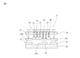
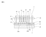
- FIG. 3 is a schematic cross-sectional view of a laminate film forming apparatus used in the first embodiment.
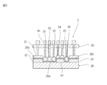
- FIG. 4 is a schematic cross-sectional view for explaining a forming process of the laminate film in the first embodiment.
- FIG. 5 is a schematic cross-sectional view for explaining a laminate film forming step according to the first embodiment.
- FIG. 6 is a schematic cross-sectional view of a laminate film manufactured in the second embodiment.
- FIG. 7 is a schematic cross-sectional view taken along line VII-VII in FIG. FIG.
- FIG. 8 is a schematic cross-sectional view for explaining a laminate film forming step in the second embodiment.
- FIG. 9 is a schematic cross-sectional view for explaining a laminate film forming step in the second embodiment.
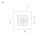
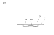
- FIG. 10 is a schematic cross-sectional view of a laminate film manufactured in the third embodiment.
- FIG. 11 is a schematic cross-sectional view taken along line XI-XI in FIG.
- FIG. 12 is a schematic cross-sectional view for explaining a laminate film forming step in the third embodiment.
- FIG. 13: is typical sectional drawing for demonstrating the formation process of the laminate film in 3rd Embodiment.
- FIG. 14 is a schematic cross-sectional view of a laminate film manufactured in the fourth embodiment.
- FIG. 14 is a schematic cross-sectional view of a laminate film manufactured in the fourth embodiment.
- FIG. 15 is a schematic sectional view taken along line XV-XV in FIG.
- FIG. 16 is typical sectional drawing for demonstrating the formation process of the laminate film in 4th Embodiment.
- FIG. 17 is typical sectional drawing for demonstrating the formation process of the laminate film in 4th Embodiment.
- FIG.1 FIG.6, FIG.10 and FIG. 14, the part in which the recessed part was provided is shown by hatching.
- FIG. 1 is a schematic cross-sectional view of a laminate film manufactured in the first embodiment.
- FIG. 2 is a schematic cross-sectional view taken along line II-II in FIG. 1st Embodiment demonstrates the manufacturing method of the laminate film 1 shown in FIG.1 and FIG.2.
- the laminate film 1 has a recess 10.
- a convex portion 10 a is provided in the concave portion 10.
- the surface of the convex portion 10 a is substantially flush with the surface of the outer portion 11 of the concave portion 10.
- FIG. 3 is a schematic cross-sectional view of the laminate film forming apparatus 2 used in the first embodiment.
- the laminate film forming apparatus 2 includes a first forming die 20 and a second forming die 30.
- the first mold 20 has a base 21 and dies 22 to 24 arranged on the base 21.
- a recess 20a is formed by the base 21 and the dies 22-24.
- the dies 22 and 23 are arranged at positions corresponding to the outer portion 11.
- the dies 22 and 23 constitute convex portions 20b and 20c located on both sides of the concave portion 20a.
- the die 24 is provided at a position corresponding to the convex portion 10a.
- the surface of the die 24 is substantially flush with the surfaces of the dies 22 and 23.
- the second mold 30 is provided to face the first mold 20.
- the second mold 30 has a plurality of punches including punches 31 to 36 and a stripper 37.
- the plurality of punches are located in the recess 20a.
- the plurality of punches are arranged in a matrix.
- Each of the plurality of punches and strippers 37 is connected to the advance / retreat mechanism 41.
- Each of the plurality of punches and strippers 37 can be advanced and retracted toward the first mold 20 by the advance / retreat mechanism 41.
- the advance / retreat mechanism 41 can be constituted by, for example, an air cylinder, an oil cylinder, a spring, a servo motor, or the like.
- FIGS. 4 and 5 are schematic cross-sectional views for explaining the forming process of the laminate film in the first embodiment.
- a method for forming a laminate film using the forming apparatus 2 will be described with reference to FIGS. 4 and 5.
- a flat film 3 (see FIG. 4) that serves as a base material of the laminate film 1 is prepared.
- the advance / retreat mechanism 41 is driven to move the stripper 37 and the punch facing the die 24 to the first mold 20 side.
- the film 3 is nipped by the stripper 37, the punch, and the dies 22-24.
- the advance / retreat mechanism 41 is driven to move the other punches to the first mold 20 side.
- the film 3 can be shape
- the molding apparatus 2 is connected to the advance / retreat mechanism 41, and is provided with a plurality of punches that can be advanced and retracted individually. For this reason, by using the molding apparatus 2, laminate films having various shapes can be suitably molded without changing the second mold 30.
- the recess 10 having a shape in which the corner is cut out as shown in FIGS. 6 and 7 is provided.
- the laminate film 1a can be manufactured.
- FIGS. 12 and 13 by arranging a die 24 lower than the dies 22 and 23, a relatively deep recess 10A and a relatively shallow recess as shown in FIGS. A laminate film 1b having 10B can be manufactured.
- a laminate film 1c having a recess 10B shallower than 10A and a recess 10C shallower than the recess 10B can be manufactured.
Landscapes
- Engineering & Computer Science (AREA)
- Mechanical Engineering (AREA)
- Blow-Moulding Or Thermoforming Of Plastics Or The Like (AREA)
- Moulds For Moulding Plastics Or The Like (AREA)
Abstract
種々の形状のラミネートフィルムを好適に成形し得るラミネートフィルムの成形装置及びラミネートフィルムの成形方法を提供する。 ラミネートフィルムの成形装置2は、第1の成形型20と、第2の成形型30とを備える。第1の成形型20は、凹部20aと、凸部20b、20cとを有する。凸部20b、20cは、凹部20aの両側に設けられている。第2の成形型30は、第1の成形型20に対向して設けられている。第2の成形型30は、複数のパンチと、進退機構41とを有する。複数のパンチは、平面視において凹部20a内に位置している。進退機構41は、複数のパンチのそれぞれに対して設けられている。進退機構41は、パンチを凹部20aに向けて進退させる。
Description
本発明は、ラミネートフィルムの成形装置及びラミネートフィルムの成形方法に関する。
近年、モバイル機器等の小型化、薄型化に伴い、二次電池等の蓄電デバイスに対して、機器のデッドスペースに合致した形状寸法を有することが求められる場合がある。例えば特許文献1には、厚肉部と薄肉部とを有する二次電池が記載されている。特許文献1に記載の二次電池は、相対的に深い凹部と、相対的に浅い凹部とを有するラミネートフィルムを有する。
凹部を有するラミネートフィルムを成形する方法としては、プレス成形法が考えられる。しかしながら、相対的に深い凹部と、相対的に浅い凹部とを有するラミネートフィルムを成形するには、専用の成形型が必要となるという問題がある。例えば、凹部の形状が異なるラミネートフィルムを成形するためには、形状の異なる複数種類の成形型を準備する必要がある。
本発明の主な目的は、種々の形状のラミネートフィルムを好適に成形し得るラミネートフィルムの成形装置及びラミネートフィルムの成形方法を提供することにある。
本発明に係るラミネートフィルムの成形装置は、第1の成形型と、第2の成形型とを備える。第1の成形型は、凹部と、凸部とを有する。凸部は、凹部の両側に設けられている。第2の成形型は、第1の成形型に対向して設けられている。第2の成形型は、複数のパンチと、進退機構とを有する。複数のパンチは、平面視において凹部内に位置している。進退機構は、複数のパンチのそれぞれに対して設けられている。進退機構は、パンチを凹部に向けて進退させる。
本発明に係るラミネートフィルムの成形装置では、第2の成形型が、凸部に対向して設けられており、パンチによるプレス時にラミネートフィルムを凸部と共に狭持するストリッパーをさらに有していてもよい。
本発明に係るラミネートフィルムの成形装置では、凹部は、相対的に浅い第1の凹部と、相対的に深い第2の凹部とを含んでいてもよい。
本発明に係るラミネートフィルムの成形装置では、複数のパンチがマトリクス状に配置されていることが好ましい。
本発明に係るラミネートフィルムの成形方法では、上記本発明に係るラミネートフィルムの成形装置を用いてラミネートフィルムを成形する。
本発明によれば、種々の形状のラミネートフィルムを好適に成形し得るラミネートフィルムの成形装置及びラミネートフィルムの成形方法を提供することができる。
以下、本発明を実施した好ましい形態の一例について説明する。但し、下記の実施形態は、単なる例示である。本発明は、下記の実施形態に何ら限定されない。
また、実施形態等において参照する各図面において、実質的に同一の機能を有する部材は同一の符号で参照することとする。また、実施形態等において参照する図面は、模式的に記載されたものである。図面に描画された物体の寸法の比率などは、現実の物体の寸法の比率などとは異なる場合がある。図面相互間においても、物体の寸法比率等が異なる場合がある。具体的な物体の寸法比率等は、以下の説明を参酌して判断されるべきである。
なお、図1,図6,図10及び図14において、凹部が設けられた部分を、ハッチングにより示している。
図1は、第1の実施形態において製造されるラミネートフィルムの模式的断面図である。図2は、図1の線II-IIにおける模式的断面図である。第1の実施形態では、図1及び図2に示すラミネートフィルム1の製造方法について説明する。ラミネートフィルム1は、凹部10を有している。凹部10内には、凸部10aが設けられている。凸部10aの表面は、凹部10の外側部分11の表面と略面一である。
図3は、第1の実施形態において使用するラミネートフィルムの成形装置2の模式的断面図である。図3に示すように、ラミネートフィルムの成形装置2は、第1の成形型20と、第2の成形型30とを有する。
第1の成形型20は、基盤21と、基盤21の上に配されたダイ22~24とを有する。これら基盤21及びダイ22~24により凹部20aが形成されている。ダイ22,23は、外側部分11に対応した位置に配されている。ダイ22,23により凹部20aの両側に位置する凸部20b、20cが構成されている。ダイ24は、凸部10aに対応した位置に設けられている。ダイ24の表面は、ダイ22,23の表面と略面一である。
第2の成形型30は、第1の成形型20に対向して設けられている。第2の成形型30は、パンチ31~36を含む複数のパンチと、ストリッパー37とを有する。平面視において、複数のパンチは、凹部20a内に位置している。複数のパンチは、マトリクス状に配されている。複数のパンチ及びストリッパー37のそれぞれは、進退機構41に接続されている。進退機構41により複数のパンチ及びストリッパー37のそれぞれが第1の成形型20に向けて進退可能である。なお、進退機構41は、例えば、エアシリンダ、オイルシリンダ、バネ、サーボモータ等により構成することができる。
図4及び図5は、第1の実施形態におけるラミネートフィルムの成形工程を説明するための模式的断面図である。次に、図4及び図5を参照しながら、成形装置2を用いてラミネートフィルムを成形する方法について説明する。
まず、ラミネートフィルム1の母材となる平板状のフィルム3(図4を参照)を用意する。次に、進退機構41を駆動し、ストリッパー37と、ダイ24と対向するパンチとを第1の成形型20側に移動させる。そして、ストリッパー37及びパンチとダイ22~24とによってフィルム3狭持する。次に、図5に示すように、進退機構41を駆動し、その他のパンチを第1の成形型20側に移動させる。これによりフィルム3を成形し、ラミネートフィルム1を完成させることができる。
以上説明したように、成形装置2では、それぞれ進退機構41に接続されており、個別に進退可能な複数のパンチが設けられている。このため、成形装置2を用いることにより、第2の成形型30を変更することなく、種々の形状のラミネートフィルムを好適に成形し得る。
例えば、図8及び図9に示すように、ダイ24の位置を凹部20aの角部に配することにより、図6及び図7に示すような、角部が切欠かれた形状の凹部10を有するラミネートフィルム1aを製造することができる。
また、図12及び図13に示すように、ダイ22,23よりも低いダイ24を配することにより、図10及び図11に示すように、相対的に深い凹部10Aと、相対的に浅い凹部10Bとを有するラミネートフィルム1bを製造することができる。
図16及び図17に示すように、ダイ22,23よりも低いダイ24aと、ダイ24aよりもさらに低いダイ24bを配することにより、図14及び図15に示すように、凹部10Aと、凹部10Aよりも浅い凹部10Bと、凹部10Bよりも浅い凹部10Cとを有するラミネートフィルム1cを製造することができる。
1,1a,1b,1c ラミネートフィルム
2 成形装置
3 フィルム
11 外側部分
20 第1の成形型
21 基盤
22~24,24a,24b ダイ
30 第2の成形型
31~36 パンチ
37 ストリッパー
41 進退機構
2 成形装置
3 フィルム
11 外側部分
20 第1の成形型
21 基盤
22~24,24a,24b ダイ
30 第2の成形型
31~36 パンチ
37 ストリッパー
41 進退機構
Claims (5)
- 凹部と、前記凹部の両側に設けられた凸部とを有する第1の成形型と、
前記第1の成形型に対向して設けられた第2の成形型と、
を備え、
前記第2の成形型は、
平面視において前記凹部内に位置している複数のパンチと、
前記複数のパンチのそれぞれに対して設けられており、当該パンチを前記凹部に向けて進退させる進退機構と、
を有する、ラミネートフィルムの成形装置。 - 前記第2の成形型は、前記凸部に対向して設けられており、前記パンチによるプレス時にラミネートフィルムを前記凸部と共に狭持するストリッパーをさらに有する、請求項1に記載のラミネートフィルムの成形装置。
- 前記凹部は、相対的に浅い第1の凹部と、相対的に深い第2の凹部とを含む、請求項1又は2に記載のラミネートフィルムの成形装置。
- 前記複数のパンチがマトリクス状に配置されている、請求項1~3のいずれか一項に記載のラミネートフィルムの成形装置。
- 請求項1~4のいずれか一項に記載のラミネートフィルムの成形装置を用いてラミネートフィルムを成形する、ラミネートフィルムの成形方法。
Applications Claiming Priority (2)
| Application Number | Priority Date | Filing Date | Title |
|---|---|---|---|
| JP2014-141933 | 2014-07-10 | ||
| JP2014141933 | 2014-07-10 |
Publications (1)
| Publication Number | Publication Date |
|---|---|
| WO2016006403A1 true WO2016006403A1 (ja) | 2016-01-14 |
Family
ID=55064043
Family Applications (1)
| Application Number | Title | Priority Date | Filing Date |
|---|---|---|---|
| PCT/JP2015/067481 Ceased WO2016006403A1 (ja) | 2014-07-10 | 2015-06-17 | ラミネートフィルムの成形装置及びラミネートフィルムの成形方法 |
Country Status (1)
| Country | Link |
|---|---|
| WO (1) | WO2016006403A1 (ja) |
Cited By (4)
| Publication number | Priority date | Publication date | Assignee | Title |
|---|---|---|---|---|
| CN108215135A (zh) * | 2017-12-29 | 2018-06-29 | 大连塑研塑料科技开发有限公司 | 塑料结构板成型方法及装置 |
| EP3657585A1 (en) * | 2018-11-23 | 2020-05-27 | Lg Chem, Ltd. | Pouch forming device and method and facility for producing secondary battery comprising the pouch forming device |
| WO2022103146A1 (ko) * | 2020-11-10 | 2022-05-19 | 주식회사 엘지에너지솔루션 | 파우치 성형장치 및 성형방법 |
| JP2023513775A (ja) * | 2020-06-04 | 2023-04-03 | エルジー エナジー ソリューション リミテッド | パウチ成形装置及び成形方法 |
Citations (2)
| Publication number | Priority date | Publication date | Assignee | Title |
|---|---|---|---|---|
| JP2009173341A (ja) * | 2007-12-25 | 2009-08-06 | Kawakami Sangyo Co Ltd | 高さが異なる中空突起を有するシート成形体およびその製造装置 |
| JP2014083573A (ja) * | 2012-10-25 | 2014-05-12 | Futaba Corp | プレス用金型、プレス装置、プレス方法 |
-
2015
- 2015-06-17 WO PCT/JP2015/067481 patent/WO2016006403A1/ja not_active Ceased
Patent Citations (2)
| Publication number | Priority date | Publication date | Assignee | Title |
|---|---|---|---|---|
| JP2009173341A (ja) * | 2007-12-25 | 2009-08-06 | Kawakami Sangyo Co Ltd | 高さが異なる中空突起を有するシート成形体およびその製造装置 |
| JP2014083573A (ja) * | 2012-10-25 | 2014-05-12 | Futaba Corp | プレス用金型、プレス装置、プレス方法 |
Cited By (10)
| Publication number | Priority date | Publication date | Assignee | Title |
|---|---|---|---|---|
| CN108215135A (zh) * | 2017-12-29 | 2018-06-29 | 大连塑研塑料科技开发有限公司 | 塑料结构板成型方法及装置 |
| EP3657585A1 (en) * | 2018-11-23 | 2020-05-27 | Lg Chem, Ltd. | Pouch forming device and method and facility for producing secondary battery comprising the pouch forming device |
| US10749147B2 (en) | 2018-11-23 | 2020-08-18 | Lg Chem, Ltd. | Pouch forming device and method and facility for producing secondary battery comprising the pouch forming device |
| JP2023513775A (ja) * | 2020-06-04 | 2023-04-03 | エルジー エナジー ソリューション リミテッド | パウチ成形装置及び成形方法 |
| JP7483904B2 (ja) | 2020-06-04 | 2024-05-15 | エルジー エナジー ソリューション リミテッド | パウチ成形装置及び成形方法 |
| US12343907B2 (en) | 2020-06-04 | 2025-07-01 | Lg Energy Solution, Ltd. | Pouch forming apparatus and method |
| WO2022103146A1 (ko) * | 2020-11-10 | 2022-05-19 | 주식회사 엘지에너지솔루션 | 파우치 성형장치 및 성형방법 |
| CN115551688A (zh) * | 2020-11-10 | 2022-12-30 | 株式会社Lg新能源 | 袋成型装置和方法 |
| US20240149498A1 (en) * | 2020-11-10 | 2024-05-09 | Lg Energy Solution, Ltd. | Apparatus and Method for Molding Pouch |
| US12365116B2 (en) * | 2020-11-10 | 2025-07-22 | Lg Energy Solution, Ltd. | Apparatus and method for molding pouch |
Similar Documents
| Publication | Publication Date | Title |
|---|---|---|
| CN102728720B (zh) | 一种冲压复合模具 | |
| JP2014528838A5 (ja) | ||
| WO2016006403A1 (ja) | ラミネートフィルムの成形装置及びラミネートフィルムの成形方法 | |
| US20140182437A1 (en) | Trimming die and punch thereof | |
| CN102728719B (zh) | 一种复合冷冲模 | |
| EP2952336A1 (en) | Method for manufacturing automotive resin part and manufacturing device of automotive resin part | |
| EP1902826A3 (en) | Molding method and molding apparatus of mold product having thin film at inner surface | |
| CN106660099B (zh) | 成形材料制造方法以及该成形材料 | |
| CN104103908A (zh) | 一种小型天线反射面的冲压胶粘复合成型方法 | |
| JP4219400B2 (ja) | 異形積層コアの製造方法 | |
| US9021846B2 (en) | Method for making metal body and metal box by using hydroforming | |
| CN204710978U (zh) | 用于成型加工一行动装置机壳之模具 | |
| JP6355128B2 (ja) | プレス成形方法 | |
| CN106736305B (zh) | 一种离合器花键毂总成的薄板冲焊成型制造方法 | |
| CN203804036U (zh) | 一种汽车车身覆盖件冲裁修边模具 | |
| CN103025448A (zh) | 倒勾部的成形方法以及具有倒勾部的成形品的制造方法 | |
| CN114951429B (zh) | 级进模精密冷锻加工装置 | |
| CN108297941A (zh) | 一种汽车后盖及其加工方法 | |
| JP6331522B2 (ja) | 絞り成形装置及び絞り成形方法 | |
| CN105382107A (zh) | 板材曲面成形冲压模具 | |
| CN213671447U (zh) | 一种超精密渐进式模具 | |
| CN204471774U (zh) | 滑块内二次抽芯机构 | |
| CN205009332U (zh) | 一种聚合物电芯的铝塑膜冲坑模具 | |
| CN211917473U (zh) | 一种连续多坑位冲膜模具 | |
| CN110252886B (zh) | 一种五金件的冲压工艺 |
Legal Events
| Date | Code | Title | Description |
|---|---|---|---|
| 121 | Ep: the epo has been informed by wipo that ep was designated in this application |
Ref document number: 15819456 Country of ref document: EP Kind code of ref document: A1 |
|
| NENP | Non-entry into the national phase |
Ref country code: DE |
|
| NENP | Non-entry into the national phase |
Ref country code: JP |
|
| 122 | Ep: pct application non-entry in european phase |
Ref document number: 15819456 Country of ref document: EP Kind code of ref document: A1 |