WO2016006391A1 - Electronic component-embedded module - Google Patents
Electronic component-embedded module Download PDFInfo
- Publication number
- WO2016006391A1 WO2016006391A1 PCT/JP2015/067122 JP2015067122W WO2016006391A1 WO 2016006391 A1 WO2016006391 A1 WO 2016006391A1 JP 2015067122 W JP2015067122 W JP 2015067122W WO 2016006391 A1 WO2016006391 A1 WO 2016006391A1
- Authority
- WO
- WIPO (PCT)
- Prior art keywords
- electronic component
- substrate
- module
- gap
- component built
- Prior art date
Links
Images


Classifications
-
- H—ELECTRICITY
- H05—ELECTRIC TECHNIQUES NOT OTHERWISE PROVIDED FOR
- H05K—PRINTED CIRCUITS; CASINGS OR CONSTRUCTIONAL DETAILS OF ELECTRIC APPARATUS; MANUFACTURE OF ASSEMBLAGES OF ELECTRICAL COMPONENTS
- H05K3/00—Apparatus or processes for manufacturing printed circuits
- H05K3/22—Secondary treatment of printed circuits
- H05K3/28—Applying non-metallic protective coatings
- H05K3/284—Applying non-metallic protective coatings for encapsulating mounted components
-
- H—ELECTRICITY
- H01—ELECTRIC ELEMENTS
- H01L—SEMICONDUCTOR DEVICES NOT COVERED BY CLASS H10
- H01L23/00—Details of semiconductor or other solid state devices
- H01L23/28—Encapsulations, e.g. encapsulating layers, coatings, e.g. for protection
- H01L23/31—Encapsulations, e.g. encapsulating layers, coatings, e.g. for protection characterised by the arrangement or shape
- H01L23/3107—Encapsulations, e.g. encapsulating layers, coatings, e.g. for protection characterised by the arrangement or shape the device being completely enclosed
- H01L23/3135—Double encapsulation or coating and encapsulation
-
- H—ELECTRICITY
- H05—ELECTRIC TECHNIQUES NOT OTHERWISE PROVIDED FOR
- H05K—PRINTED CIRCUITS; CASINGS OR CONSTRUCTIONAL DETAILS OF ELECTRIC APPARATUS; MANUFACTURE OF ASSEMBLAGES OF ELECTRICAL COMPONENTS
- H05K3/00—Apparatus or processes for manufacturing printed circuits
- H05K3/22—Secondary treatment of printed circuits
- H05K3/28—Applying non-metallic protective coatings
- H05K3/281—Applying non-metallic protective coatings by means of a preformed insulating foil
-
- H—ELECTRICITY
- H05—ELECTRIC TECHNIQUES NOT OTHERWISE PROVIDED FOR
- H05K—PRINTED CIRCUITS; CASINGS OR CONSTRUCTIONAL DETAILS OF ELECTRIC APPARATUS; MANUFACTURE OF ASSEMBLAGES OF ELECTRICAL COMPONENTS
- H05K3/00—Apparatus or processes for manufacturing printed circuits
- H05K3/30—Assembling printed circuits with electric components, e.g. with resistor
- H05K3/32—Assembling printed circuits with electric components, e.g. with resistor electrically connecting electric components or wires to printed circuits
- H05K3/34—Assembling printed circuits with electric components, e.g. with resistor electrically connecting electric components or wires to printed circuits by soldering
- H05K3/341—Surface mounted components
- H05K3/3431—Leadless components
- H05K3/3436—Leadless components having an array of bottom contacts, e.g. pad grid array or ball grid array components
-
- H—ELECTRICITY
- H01—ELECTRIC ELEMENTS
- H01L—SEMICONDUCTOR DEVICES NOT COVERED BY CLASS H10
- H01L2224/00—Indexing scheme for arrangements for connecting or disconnecting semiconductor or solid-state bodies and methods related thereto as covered by H01L24/00
- H01L2224/01—Means for bonding being attached to, or being formed on, the surface to be connected, e.g. chip-to-package, die-attach, "first-level" interconnects; Manufacturing methods related thereto
- H01L2224/10—Bump connectors; Manufacturing methods related thereto
- H01L2224/12—Structure, shape, material or disposition of the bump connectors prior to the connecting process
- H01L2224/13—Structure, shape, material or disposition of the bump connectors prior to the connecting process of an individual bump connector
- H01L2224/13001—Core members of the bump connector
- H01L2224/13099—Material
- H01L2224/131—Material with a principal constituent of the material being a metal or a metalloid, e.g. boron [B], silicon [Si], germanium [Ge], arsenic [As], antimony [Sb], tellurium [Te] and polonium [Po], and alloys thereof
-
- H—ELECTRICITY
- H01—ELECTRIC ELEMENTS
- H01L—SEMICONDUCTOR DEVICES NOT COVERED BY CLASS H10
- H01L2224/00—Indexing scheme for arrangements for connecting or disconnecting semiconductor or solid-state bodies and methods related thereto as covered by H01L24/00
- H01L2224/01—Means for bonding being attached to, or being formed on, the surface to be connected, e.g. chip-to-package, die-attach, "first-level" interconnects; Manufacturing methods related thereto
- H01L2224/10—Bump connectors; Manufacturing methods related thereto
- H01L2224/15—Structure, shape, material or disposition of the bump connectors after the connecting process
- H01L2224/16—Structure, shape, material or disposition of the bump connectors after the connecting process of an individual bump connector
- H01L2224/161—Disposition
- H01L2224/16151—Disposition the bump connector connecting between a semiconductor or solid-state body and an item not being a semiconductor or solid-state body, e.g. chip-to-substrate, chip-to-passive
- H01L2224/16221—Disposition the bump connector connecting between a semiconductor or solid-state body and an item not being a semiconductor or solid-state body, e.g. chip-to-substrate, chip-to-passive the body and the item being stacked
- H01L2224/16225—Disposition the bump connector connecting between a semiconductor or solid-state body and an item not being a semiconductor or solid-state body, e.g. chip-to-substrate, chip-to-passive the body and the item being stacked the item being non-metallic, e.g. insulating substrate with or without metallisation
- H01L2224/16227—Disposition the bump connector connecting between a semiconductor or solid-state body and an item not being a semiconductor or solid-state body, e.g. chip-to-substrate, chip-to-passive the body and the item being stacked the item being non-metallic, e.g. insulating substrate with or without metallisation the bump connector connecting to a bond pad of the item
-
- H—ELECTRICITY
- H01—ELECTRIC ELEMENTS
- H01L—SEMICONDUCTOR DEVICES NOT COVERED BY CLASS H10
- H01L24/00—Arrangements for connecting or disconnecting semiconductor or solid-state bodies; Methods or apparatus related thereto
- H01L24/01—Means for bonding being attached to, or being formed on, the surface to be connected, e.g. chip-to-package, die-attach, "first-level" interconnects; Manufacturing methods related thereto
- H01L24/10—Bump connectors ; Manufacturing methods related thereto
- H01L24/12—Structure, shape, material or disposition of the bump connectors prior to the connecting process
- H01L24/13—Structure, shape, material or disposition of the bump connectors prior to the connecting process of an individual bump connector
-
- H—ELECTRICITY
- H01—ELECTRIC ELEMENTS
- H01L—SEMICONDUCTOR DEVICES NOT COVERED BY CLASS H10
- H01L24/00—Arrangements for connecting or disconnecting semiconductor or solid-state bodies; Methods or apparatus related thereto
- H01L24/01—Means for bonding being attached to, or being formed on, the surface to be connected, e.g. chip-to-package, die-attach, "first-level" interconnects; Manufacturing methods related thereto
- H01L24/10—Bump connectors ; Manufacturing methods related thereto
- H01L24/15—Structure, shape, material or disposition of the bump connectors after the connecting process
- H01L24/16—Structure, shape, material or disposition of the bump connectors after the connecting process of an individual bump connector
-
- H—ELECTRICITY
- H01—ELECTRIC ELEMENTS
- H01L—SEMICONDUCTOR DEVICES NOT COVERED BY CLASS H10
- H01L25/00—Assemblies consisting of a plurality of individual semiconductor or other solid state devices ; Multistep manufacturing processes thereof
- H01L25/16—Assemblies consisting of a plurality of individual semiconductor or other solid state devices ; Multistep manufacturing processes thereof the devices being of types provided for in two or more different main groups of groups H01L27/00 - H01L33/00, or in a single subclass of H10K, H10N, e.g. forming hybrid circuits
-
- H—ELECTRICITY
- H01—ELECTRIC ELEMENTS
- H01L—SEMICONDUCTOR DEVICES NOT COVERED BY CLASS H10
- H01L2924/00—Indexing scheme for arrangements or methods for connecting or disconnecting semiconductor or solid-state bodies as covered by H01L24/00
- H01L2924/10—Details of semiconductor or other solid state devices to be connected
- H01L2924/11—Device type
- H01L2924/14—Integrated circuits
-
- H—ELECTRICITY
- H01—ELECTRIC ELEMENTS
- H01L—SEMICONDUCTOR DEVICES NOT COVERED BY CLASS H10
- H01L2924/00—Indexing scheme for arrangements or methods for connecting or disconnecting semiconductor or solid-state bodies as covered by H01L24/00
- H01L2924/19—Details of hybrid assemblies other than the semiconductor or other solid state devices to be connected
- H01L2924/1901—Structure
- H01L2924/1904—Component type
- H01L2924/19041—Component type being a capacitor
-
- H—ELECTRICITY
- H01—ELECTRIC ELEMENTS
- H01L—SEMICONDUCTOR DEVICES NOT COVERED BY CLASS H10
- H01L2924/00—Indexing scheme for arrangements or methods for connecting or disconnecting semiconductor or solid-state bodies as covered by H01L24/00
- H01L2924/19—Details of hybrid assemblies other than the semiconductor or other solid state devices to be connected
- H01L2924/1901—Structure
- H01L2924/1904—Component type
- H01L2924/19042—Component type being an inductor
-
- H—ELECTRICITY
- H01—ELECTRIC ELEMENTS
- H01L—SEMICONDUCTOR DEVICES NOT COVERED BY CLASS H10
- H01L2924/00—Indexing scheme for arrangements or methods for connecting or disconnecting semiconductor or solid-state bodies as covered by H01L24/00
- H01L2924/19—Details of hybrid assemblies other than the semiconductor or other solid state devices to be connected
- H01L2924/1901—Structure
- H01L2924/1904—Component type
- H01L2924/19043—Component type being a resistor
-
- H—ELECTRICITY
- H01—ELECTRIC ELEMENTS
- H01L—SEMICONDUCTOR DEVICES NOT COVERED BY CLASS H10
- H01L2924/00—Indexing scheme for arrangements or methods for connecting or disconnecting semiconductor or solid-state bodies as covered by H01L24/00
- H01L2924/19—Details of hybrid assemblies other than the semiconductor or other solid state devices to be connected
- H01L2924/191—Disposition
- H01L2924/19101—Disposition of discrete passive components
- H01L2924/19105—Disposition of discrete passive components in a side-by-side arrangement on a common die mounting substrate
-
- H—ELECTRICITY
- H05—ELECTRIC TECHNIQUES NOT OTHERWISE PROVIDED FOR
- H05K—PRINTED CIRCUITS; CASINGS OR CONSTRUCTIONAL DETAILS OF ELECTRIC APPARATUS; MANUFACTURE OF ASSEMBLAGES OF ELECTRICAL COMPONENTS
- H05K1/00—Printed circuits
- H05K1/02—Details
- H05K1/11—Printed elements for providing electric connections to or between printed circuits
- H05K1/111—Pads for surface mounting, e.g. lay-out
-
- H—ELECTRICITY
- H05—ELECTRIC TECHNIQUES NOT OTHERWISE PROVIDED FOR
- H05K—PRINTED CIRCUITS; CASINGS OR CONSTRUCTIONAL DETAILS OF ELECTRIC APPARATUS; MANUFACTURE OF ASSEMBLAGES OF ELECTRICAL COMPONENTS
- H05K2201/00—Indexing scheme relating to printed circuits covered by H05K1/00
- H05K2201/09—Shape and layout
- H05K2201/09009—Substrate related
- H05K2201/09036—Recesses or grooves in insulating substrate
-
- H—ELECTRICITY
- H05—ELECTRIC TECHNIQUES NOT OTHERWISE PROVIDED FOR
- H05K—PRINTED CIRCUITS; CASINGS OR CONSTRUCTIONAL DETAILS OF ELECTRIC APPARATUS; MANUFACTURE OF ASSEMBLAGES OF ELECTRICAL COMPONENTS
- H05K2201/00—Indexing scheme relating to printed circuits covered by H05K1/00
- H05K2201/09—Shape and layout
- H05K2201/09209—Shape and layout details of conductors
- H05K2201/09372—Pads and lands
- H05K2201/09427—Special relation between the location or dimension of a pad or land and the location or dimension of a terminal
-
- H—ELECTRICITY
- H05—ELECTRIC TECHNIQUES NOT OTHERWISE PROVIDED FOR
- H05K—PRINTED CIRCUITS; CASINGS OR CONSTRUCTIONAL DETAILS OF ELECTRIC APPARATUS; MANUFACTURE OF ASSEMBLAGES OF ELECTRICAL COMPONENTS
- H05K2201/00—Indexing scheme relating to printed circuits covered by H05K1/00
- H05K2201/10—Details of components or other objects attached to or integrated in a printed circuit board
- H05K2201/10613—Details of electrical connections of non-printed components, e.g. special leads
- H05K2201/10621—Components characterised by their electrical contacts
- H05K2201/10674—Flip chip
-
- H—ELECTRICITY
- H05—ELECTRIC TECHNIQUES NOT OTHERWISE PROVIDED FOR
- H05K—PRINTED CIRCUITS; CASINGS OR CONSTRUCTIONAL DETAILS OF ELECTRIC APPARATUS; MANUFACTURE OF ASSEMBLAGES OF ELECTRICAL COMPONENTS
- H05K2203/00—Indexing scheme relating to apparatus or processes for manufacturing printed circuits covered by H05K3/00
- H05K2203/11—Treatments characterised by their effect, e.g. heating, cooling, roughening
- H05K2203/1178—Means for venting or for letting gases escape
-
- H—ELECTRICITY
- H05—ELECTRIC TECHNIQUES NOT OTHERWISE PROVIDED FOR
- H05K—PRINTED CIRCUITS; CASINGS OR CONSTRUCTIONAL DETAILS OF ELECTRIC APPARATUS; MANUFACTURE OF ASSEMBLAGES OF ELECTRICAL COMPONENTS
- H05K2203/00—Indexing scheme relating to apparatus or processes for manufacturing printed circuits covered by H05K3/00
- H05K2203/13—Moulding and encapsulation; Deposition techniques; Protective layers
- H05K2203/1305—Moulding and encapsulation
- H05K2203/1311—Foil encapsulation, e.g. of mounted components
-
- H—ELECTRICITY
- H05—ELECTRIC TECHNIQUES NOT OTHERWISE PROVIDED FOR
- H05K—PRINTED CIRCUITS; CASINGS OR CONSTRUCTIONAL DETAILS OF ELECTRIC APPARATUS; MANUFACTURE OF ASSEMBLAGES OF ELECTRICAL COMPONENTS
- H05K2203/00—Indexing scheme relating to apparatus or processes for manufacturing printed circuits covered by H05K3/00
- H05K2203/13—Moulding and encapsulation; Deposition techniques; Protective layers
- H05K2203/1305—Moulding and encapsulation
- H05K2203/1322—Encapsulation comprising more than one layer
-
- H—ELECTRICITY
- H05—ELECTRIC TECHNIQUES NOT OTHERWISE PROVIDED FOR
- H05K—PRINTED CIRCUITS; CASINGS OR CONSTRUCTIONAL DETAILS OF ELECTRIC APPARATUS; MANUFACTURE OF ASSEMBLAGES OF ELECTRICAL COMPONENTS
- H05K3/00—Apparatus or processes for manufacturing printed circuits
- H05K3/30—Assembling printed circuits with electric components, e.g. with resistor
- H05K3/32—Assembling printed circuits with electric components, e.g. with resistor electrically connecting electric components or wires to printed circuits
- H05K3/34—Assembling printed circuits with electric components, e.g. with resistor electrically connecting electric components or wires to printed circuits by soldering
- H05K3/341—Surface mounted components
- H05K3/3431—Leadless components
-
- H—ELECTRICITY
- H05—ELECTRIC TECHNIQUES NOT OTHERWISE PROVIDED FOR
- H05K—PRINTED CIRCUITS; CASINGS OR CONSTRUCTIONAL DETAILS OF ELECTRIC APPARATUS; MANUFACTURE OF ASSEMBLAGES OF ELECTRICAL COMPONENTS
- H05K3/00—Apparatus or processes for manufacturing printed circuits
- H05K3/30—Assembling printed circuits with electric components, e.g. with resistor
- H05K3/32—Assembling printed circuits with electric components, e.g. with resistor electrically connecting electric components or wires to printed circuits
- H05K3/34—Assembling printed circuits with electric components, e.g. with resistor electrically connecting electric components or wires to printed circuits by soldering
- H05K3/3494—Heating methods for reflowing of solder
-
- Y—GENERAL TAGGING OF NEW TECHNOLOGICAL DEVELOPMENTS; GENERAL TAGGING OF CROSS-SECTIONAL TECHNOLOGIES SPANNING OVER SEVERAL SECTIONS OF THE IPC; TECHNICAL SUBJECTS COVERED BY FORMER USPC CROSS-REFERENCE ART COLLECTIONS [XRACs] AND DIGESTS
- Y02—TECHNOLOGIES OR APPLICATIONS FOR MITIGATION OR ADAPTATION AGAINST CLIMATE CHANGE
- Y02P—CLIMATE CHANGE MITIGATION TECHNOLOGIES IN THE PRODUCTION OR PROCESSING OF GOODS
- Y02P70/00—Climate change mitigation technologies in the production process for final industrial or consumer products
- Y02P70/50—Manufacturing or production processes characterised by the final manufactured product
Definitions
- the present invention relates to an electronic component built-in module, and more specifically, a gas (such as water vapor) generated from a liquid component (water or the like) contained in a sealing resin inside even when heated when soldering to a substrate or the like of an electronic device.
- a gas such as water vapor
- This is related to a module with a built-in electronic component that is less likely to cause an electrical short circuit or poor conduction due to ().
- An electronic component built-in module having a structure in which a plurality of electronic components are mounted on a substrate and these electronic components are covered with a sealing resin is used in an electronic device or the like as a high-function module.
- Solder flash is the solder used to join the land electrode on the board and the terminal electrode of the electronic component in the electronic component built-in module by heating when the electronic component built-in module is soldered to the board of the electronic device. It refers to the phenomenon of remelting and leaching into fine gaps, or further leaching of the solder to electrically short-circuit the terminal electrodes of the electronic component.
- Patent Document 1 For example, in an electronic component built-in module (circuit board) disclosed in Japanese Patent Application Laid-Open No. 2011-165695 (Patent Document 1), by devising the shape of land electrodes (electrode pads) formed on the board, for example, By dividing the land electrode or the like, it is easy to fill the sealing resin between the substrate and the mounted electronic component, thereby preventing the occurrence of solder flash. That is, in the electronic component built-in module disclosed in Patent Document 1, the electronic component built-in module is mounted on a substrate of an electronic device or the like by densely filling a sealing resin around the mounted electronic component and generating no gap. Even if the solder is remelted by heating at the time of soldering, the terminal electrodes of the electronic component are not electrically short-circuited.
- Patent Document 2 As another method, in the electronic component built-in module (semiconductor device) disclosed in Japanese Patent Laid-Open No. 2005-302835 (Patent Document 2), conversely, a sealing resin is provided between the substrate and the mounted electronic component. The solder flash is prevented by making the space without filling.
- FIG. 8 shows an electronic component built-in module 500 disclosed in Patent Document 2.
- the electronic component built-in module 500 includes a substrate 101.
- a land electrode 102 is formed on the main surface of the substrate 101.
- 104 is implemented. Specifically, the terminal electrode 103 a of the electronic component 103 and the flip chip electrode of the electronic component 104 are fixed to the land electrode 102 by a brazing material, for example, solder 105.
- examples of the electronic component 103 in which the terminal electrodes 103a are formed at both ends of the component main body include a capacitor element, a coil element, and a resistance element.
- examples of the electronic component 104 having a plurality of flip chip electrodes formed on the bottom surface of the component body include a surface acoustic wave device, a semiconductor device, and an integrated circuit device.
- a resin film 106 is formed so as to cover the electronic components 103 and 104 mounted on the substrate 101.
- a sealing resin 107 is formed on the resin film 106.
- the sealing resin 107 is solidified or cured after being disposed on the film 106 in a semi-molten state. Since the sealing resin 107 has the film 106, the sealing resin 107 does not flow into the gap between the substrate 101 and the electronic components 103 and 104, and a space S1 is formed in the gap between the substrate 101 and the electronic components 103 and 104, respectively. Yes.
- the sealing resin 107 is not filled between the substrate 101 and the mounted electronic components 103 and 104, and the space S1 is formed. Even when the solder 105 is remelted and expanded due to heating when soldering (not shown) or the like, the expansion of the volume can be absorbed in the space S1, so a solder flash occurs. It is difficult to do.
- the electronic component built-in module 500 disclosed in Patent Document 2 is less likely to cause solder flash when the electronic component built-in module 500 is soldered to a substrate of an electronic device or the like.
- FIG. 9A and 9B are cross-sectional views of the electronic component built-in module 500 in which the land electrode 102, the electronic components 103 and 104, the solder 105, and the film 106 are omitted. Therefore, only the substrate 101 and the sealing resin 107 are shown in FIG. 9A, and only the sealing resin 107 is shown in FIG. 9B. Note that FIG. 9B illustrates a cross section of a portion XX in FIG.
- the sealing resin 107 is solidified or cured after being disposed on the film 106 in a semi-molten state.
- the liquid component contained in the sealing resin 107 is sequentially dried from the outer surface side of the sealing resin 107, the liquid resin contained in the sealing resin 107 near the center portion or on the substrate 101 of the sealing resin 107. The liquid component tends to remain on the side in contact.
- M1, M2, and M3 indicate portions where the liquid component remains in the sealing resin 107, and the residual concentration of the liquid component is higher in the order of M1, M2, and M3.
- the electronic component built-in module 500 in which the liquid component remains in this way is heated to be soldered to a substrate (not shown) of an electronic device, it is included in the M1, M2, and M3 portions of the sealing resin 107.
- the liquid component thus formed becomes gas (water vapor or the like) and expands in the direction indicated by the black arrow in FIGS. 9 (A) and 9 (B). That is, the gas expands in a direction perpendicular to the main surface of the substrate 101, but also expands in the direction parallel to the main surface of the substrate 101 from the vicinity of the central portion of the substrate 101 toward the outer edge of the substrate 101. .
- the expansion of the gas may cause an electrical short circuit between the terminal electrodes 103a of the electronic component 103 or may cause a conduction failure between the terminal electrode 103a of the electronic component 103 and the land electrode 102. This will be described in more detail with reference to FIGS.
- FIGS. 10A and 10B are cross-sectional views of the main part of the electronic component built-in module 500.
- FIG. 10A shows a state before the electronic component built-in module 500 is soldered to a substrate (not shown) of an electronic device.
- FIG. 10B shows a state where the electronic component built-in module 500 is heated for soldering.
- an electronic component 103 in which terminal electrodes 103a are formed on both ends of a component main body is mounted on a substrate 101 using land electrodes 102.
- the terminal electrode 103 a of the electronic component 103 is fixed to the land electrode 102 with the solder 105.
- a resin film 106 is formed so as to cover the electronic component 103 mounted on the substrate 101.
- a sealing resin 107 is formed on the resin film 106. Since the sealing resin 107 has the film 106, the sealing resin 107 does not flow into the gap between the substrate 101 and the electronic component 103, and a space S 1 is formed in the gap between the substrate 101 and the electronic component 103.
- the solder 105 When the electronic component built-in module 500 is heated to be soldered to a substrate or the like of an electronic device, the solder 105 is remelted, and as shown in FIG. 10B, the liquid component contained in the sealing resin 107 is It becomes gas and expands in a direction parallel to the main surface of the substrate 101 indicated by the black arrow. Since the film 106 allows gas to pass therethrough, the gas may enter between the terminal electrode 103a of the electronic component 103 and the film 106 to push out the molten solder 105 (the right-side solder 105 in the figure) to form a space S2. It was.
- the extruded solder 105 flows into the space S1 between the substrate 101 and the electronic component 103, and the opposite land electrode 102 (left land electrode 102 in the figure) and solder 105 (left solder 105 in the figure). There was a case where it reached. That is, there is a case where the terminal electrodes 103a of the electronic component 103 are electrically short-circuited.
- the space S2 is formed, the melted solder 105 is pushed out, and the terminal electrode 103a of the electronic component 103 and the land electrode 102 may be poorly connected.
- the electronic component built-in module 500 disclosed in Patent Document 2 is provided with a space S1 between the substrate 101 and the electronic component 103, so that a solder flash for soldering to a substrate or the like of an electronic device can be obtained.
- the generation is suppressed, when the sealing resin 107 contains a liquid component, there is a possibility that an electrical short circuit or a conduction failure may occur inside.
- the electronic component built-in module of the present invention includes a substrate, a land electrode formed on at least one main surface of the substrate, An electronic component having at least one pair of terminal electrodes, the terminal electrode being fixed to the land electrode by a brazing material, and an electronic component mounted on the main surface of the substrate and covering the electronic component on the main surface of the substrate A sealing resin, and a space is provided between the substrate and the electronic component, and at least one fixing portion between the land electrode made of the brazing material and the terminal electrode of the electronic component other than the fixing portion facing the space In the place, a gap is formed along the fixed portion.
- the expanded gas can pass through the gap, so that the molten brazing material (solder or the like) is pushed out into the space between the substrate and the electronic component. There is no occurrence of electrical short circuit or conduction failure.
- the terminal electrode of the electronic component is composed of, for example, cap-shaped terminal electrodes formed at both ends of the electronic component main body.
- a cap-shaped terminal electrode there is no gap to allow gas to pass in the vicinity of the fixed portion between the land electrode and the terminal electrode by the brazing material, and when soldering the electronic component built-in module to the substrate of the electronic device, Since the brazing material is easily affected by the expanded gas and the brazing material is pushed out and an electrical short circuit or conduction failure is likely to occur inside, the effect of applying the present invention is great.
- the electronic component and the substrate may be covered with a film, and the film may be covered with a sealing resin.
- a space can be easily provided between the substrate and the electronic component.
- the gap includes, for example, a gap formed between the substrate, the fixed portion, and the film.
- gap consists of the clearance gap formed between the board
- the gap is formed by making the width of the land electrode smaller than the width of the terminal electrode in the land electrode and the terminal electrode facing each other in the fixed portion.
- the width of the land electrode and the width of the terminal electrode refer to the width of the land electrode and the width of the terminal electrode that appear when the fixed portion is cut in the width direction of the electronic component (for example, the cross section of FIG. 2). The width of the land electrode and the width of the terminal electrode appearing in the figure).
- gap is formed of the groove
- a plurality of methods may be used in combination as the above-described void formation method.
- the gap along the fixed portion can be formed, for example, in a direction connecting the central portion of the substrate and the electronic component.
- the direction in which the gas in the sealing resin expands can coincide with the direction in which the voids are formed, the gas can easily pass through the voids.
- another electronic component having a plurality of flip chip electrodes formed on the bottom surface may be further flip-chip mounted on the main surface of the substrate.
- Examples of such electronic components include a surface acoustic wave device, a semiconductor device, an integrated circuit device, and the like. In this case, the electronic component built-in module can be made more sophisticated.
- the electronic component built-in module of the present invention can pass gas (water vapor or the like) through a gap along the fixed portion, when the electronic component built-in module is soldered to a substrate of an electronic device or the like, it is used as a sealing resin. Due to the gas generated from the contained liquid component (water or the like), the occurrence of electrical short circuit or poor conduction inside is suppressed.
- FIG. 1 is an exploded plan view of the electronic component built-in module 100 according to the first embodiment.
- FIG. 1 shows an internal state of the electronic component built-in module 100 from which the film 6 and the sealing resin 7 are removed. However, in FIG. 1, the positions of the gaps S formed by the film 6 are indicated by broken lines.
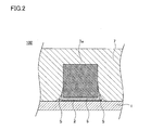
- FIG. 2 is a cross-sectional view of a main part of the electronic component built-in module 100, and shows a YY portion of FIG.
- FIGS. 3A and 3B are perspective views illustrating steps performed in an example of a method for manufacturing the electronic component built-in module 100.
- FIG. 4 is a continuation of FIG. 3B, and is a perspective view showing a process performed in an example of a method for manufacturing the electronic component built-in module 100.
- FIG. 1 is an exploded plan view of the electronic component built-in module 100 according to the first embodiment.
- FIG. 1 shows an internal state of the electronic component built-in module 100 from which the film 6 and the sealing resin 7 are removed. However
- FIG. 5 is a cross-sectional view of an essential part showing an electronic component built-in module 200 according to the second embodiment.
- FIG. 6 is a cross-sectional view of an essential part showing an electronic component built-in module 300 according to the third embodiment.
- FIG. 7 is a cross-sectional view of an essential part showing an electronic component built-in module 400 according to the fourth embodiment.
- FIG. 8 is a cross-sectional view showing a conventional electronic component built-in module 500 disclosed in Patent Document 2.
- FIGS. 9A and 9B are cross-sectional views showing a conventional electronic component built-in module 500, and FIG. 9B shows an XX portion of FIG. 9A.
- FIGS. 9A and 9B are cross-sectional views showing a conventional electronic component built-in module 500, and FIG. 9B shows an XX portion of FIG. 9A.
- FIGS. 9A and 9B are cross-sectional views showing a conventional electronic component built-in module 500, and FIG. 9B shows an XX portion of FIG
- FIGS. 10A and 10B are cross-sectional views of main parts of a conventional electronic component built-in module 500, and FIG. 10A shows the electronic component built-in module 500 as an electronic device substrate (not shown). FIG. 10B shows a state in which the electronic component built-in module 500 is heated for soldering.
- FIG. 1 and 2 each show an electronic component built-in module 100 according to the first embodiment.
- 1 is an exploded plan view
- FIG. 2 is a cross-sectional view.
- FIG. 2 corresponds to the YY portion of FIG. 1 shows an internal state of the electronic component built-in module 100 from which the sealing resin 7 shown in FIG. 2 has been removed.
- the position of the space S formed by the sealing resin 7 is indicated by a broken line.
- the electronic component built-in module 100 includes a substrate 1.
- the substrate 1 is made of, for example, resin or ceramic.
- the substrate 1 may be formed in a multilayer structure.
- substrate 1 may incorporate the electronic component inside.
- the land electrode 2 is formed on the main surface of the substrate 1.
- the material of the land electrode 2 is arbitrary, but, for example, copper, aluminum or the like is used.
- wiring electrodes for connecting the land electrodes 2 and the like may be formed on the main surface of the substrate 1.
- An electronic component 3 in which terminal electrodes 3a are formed on both ends of a component body using a land electrode 2, and an electronic component in which a plurality of flip chip electrodes (not shown) are formed on the bottom surface of the component body. 4 is implemented. Specifically, the terminal electrode 3 a of the electronic component 3 and the flip chip electrode of the electronic component 4 are fixed to the land electrode 2 by a brazing material, for example, solder 5.
- a sealing resin 7 is formed so as to cover the electronic components 3 and 4 mounted on the substrate 1.
- the material of the sealing resin 7 is arbitrary, for example, a curable resin such as an epoxy resin or a polyimide resin can be used.
- a gap S which is an important component for the present invention, is formed by the gap formed between the substrate 1, the fixed portion of the land electrode 2 and the terminal electrode 3a by the solder 5, and the sealing resin 7. .
- the gap S is formed along the fixed portion by the solder 5, so that the space around the fixed portion is in contact with the surrounding resin material together with the space provided between the substrate 1 and the electronic component 3. There are voids that do not.
- the sealing resin 7 is a curable resin, it is cured after being placed on the electronic components 3 and 4 in a semi-molten state. A space (not shown) is formed in each gap between the substrate 1 and the electronic components 3 and 4.
- the liquid component remains in the sealing resin or the sealing resin absorbs the liquid component. is there.
- the electronic component built-in module 100 even if a liquid component remains in the sealing resin at the time of manufacture, or even if the sealing resin absorbs the liquid component during storage, the electronic device When soldering to a substrate or the like, no electrical short circuit or poor conduction occurs inside.
- the completed electronic component built-in module is placed under high humidity for a certain period of time to absorb liquid components and then heated and soldered to the board.
- the electronic component built-in module 100 according to the present embodiment does not cause an electrical short circuit or poor conduction inside even in such an inspection.
- the electronic component built-in module 100 according to the first embodiment having the above-described structure can be manufactured through, for example, the steps shown in FIGS. 3 (A), 3 (B), and FIG.
- a land electrode 2 is formed on a substrate 1.
- the land electrode 2 can be formed, for example, by attaching a copper foil to the entire main surface of the substrate 1 and etching it into a desired shape.
- an electronic component 3 having terminal electrodes 3a formed on both ends of the component body on the land electrode 2 is formed. Temporarily fix.
- the electronic component 4 having a plurality of flip chip electrodes formed on the bottom surface of the component body is temporarily fixed on the land electrode 2 coated with cream solder 5 '.
- the cream solder 5 ′ is heated to melt, and then cooled to solidify, whereby the terminal electrode 3 a of the electronic component 3 is fixed to the land electrode 2 by the solder 5.
- the flip chip electrode of the electronic component 4 is fixed to the land electrode 2 with the solder 5.
- the electronic component built-in module 100 is completed by covering the substrate 1 and the electronic components 3 and 4 mounted on the substrate 1 with the sealing resin 7.
- the step of covering the electronic components 3 and 4 with the sealing resin 7 is performed by, for example, placing the semi-molten sealing resin 7 on the electronic components 3 and 4 when the sealing resin 7 is a curable resin.
- the lower surface is deformed according to the shape of the electronic components 3 and 4 and the upper surface is flattened, and then the sealing resin 7 is cured by a method such as thermosetting or photocuring.
- the gap S is formed in this step, but the temperature, melted state, etc. of the sealing resin 7 are adjusted, and the magnitude of the pressure for pressing the sealing resin 7 toward the substrate, the pressing speed, etc. are adjusted.
- the gap S can be easily formed.
- the gap S is formed by a gap formed between the substrate 1, a fixed portion between the land electrode 2 and the terminal electrode 3 a by the solder 5, and the sealing resin 7. .
- the method for forming the void S is not limited to this method.
- the gap S may be formed by making the width of the land electrode 2 and the terminal electrode 3a opposite to each other in the fixed portion smaller than the width of the terminal electrode 3a.
- a groove may be formed on the main surface of the substrate 1 and the gap S may be formed by the groove.
- FIG. 5 shows an electronic component built-in module 200 according to the second embodiment. However, FIG. 5 is a cross-sectional view of the main part of the electronic component built-in module 200.
- the width of the land electrode 2 and the terminal electrode 3a facing each other in the fixed portion is slightly larger than the width of the terminal electrode 3a. (See FIG. 2).
- the width W1 of the land electrode 2 is made smaller than the width W2 of the terminal electrode 3a.
- the gap S can be easily formed between the substrate 1, the fixed portion of the land electrode 2 and the terminal electrode 3a by the solder 5, and the sealing resin 7. It has become.
- FIG. 6 shows an electronic component built-in module 300 according to the third embodiment. However, FIG. 6 is a cross-sectional view of the main part of the electronic component built-in module 300.
- a groove 1a is formed in advance on the main surface of the substrate 1, and the groove 1a is defined as a gap S.
- FIG. 7 shows an electronic component built-in module 400 according to the fourth embodiment. However, FIG. 7 is a cross-sectional view of the main part of the electronic component built-in module 400.
- the film 6 is formed so as to cover the electronic components 3 and 4 mounted on the substrate 1 according to the first embodiment.
- gap S which is an important component for this invention is formed by the clearance gap formed between the board
- FIG. . The gap S is formed along the fixed portion by the solder 5, so that the space around the fixed portion is in contact with the surrounding resin material together with the space provided between the substrate 1 and the electronic component 3. There are voids that do not.
- a sealing resin 7 is formed on the film 6.
- the film 6 of this embodiment allows gas to permeate.
- the material of the film 6 is not ask
- the film 6 may be a single layer or may have a laminated structure including a plurality of layers.
- the film 6 is attached to the substrate 1 and the mounted electronic components 3 and 4 by a method capable of following a complicated surface shape, such as vacuum lamination, rubber press, or isostatic pressing, and is cured by heat or light. It is hardened by such a method.
- the electronic component built-in module 400 includes the film 6, it is easy to form a space between the electronic components 3 and 4 and the substrate 1. Further, by adjusting the processing conditions when covering the film 6, the rigidity of the film 6 itself, and the pressure when the film 6 is applied, the substrate 1, the fixed portion between the land electrode 2 and the terminal electrode 3 a by the solder 5, The gap S can be easily formed between the film 6 and the film 6. Furthermore, also in the fourth embodiment, since the gap S is formed, it is not affected by the gas due to the liquid component contained in the sealing resin 7, and an electrical short circuit or conduction failure of the electronic component occurs. do not do.
- the film 6 applied to the electronic component built-in module 400 according to the fourth embodiment can also be applied to the electronic component built-in modules 200 and 300 according to the second and third embodiments described above.
- the gap S formed around the fixed portion of the solder 5 does not need to be provided at the connection portion between the terminal electrode 3a and the land electrode 2 at both ends of the electronic component 3, and is provided only on one terminal electrode side. It may be.
- gap S does not need to be provided in the circumference
- the gap S formed around the fixed portion of the solder 5 is provided for all the electronic components 3 mounted on the substrate 1. However, the gap S is not applied to a pattern having a large gap between the land electrodes.
- 1 substrate, 2: land electrode, 3: electronic component (electronic component on which at least one pair of terminal electrodes 3a is formed), 3a: terminal electrode, 4: electronic component (a plurality of flip chip electrodes are formed on the bottom surface) Electronic component), 5: solder, 5 ′: cream solder, 6: film, 7: sealing resin, S: gap, 100, 200, 300, 400: module with built-in electronic component.
Abstract
In the present invention, the following are provided: a substrate (1); a land electrode (2); an electronic component (3) which includes at least one pair of terminal electrodes (3a); and a sealing resin (7). A void is provided between the substrate (1) and the electronic component (3). In a fixing section formed by solder (brazing material) (5) between the land electrode (2) and the terminal electrodes (3a) of the electronic component (3), at a site which faces the void and is other than the fixing section, at least one space (S) is formed following the fixing section.
Description
本願発明は電子部品内蔵モジュールに関し、更に詳しくは、電子機器の基板等にはんだ付けする際に加熱しても、内部において封止樹脂に含まれる液体成分(水等)から発生したガス(水蒸気等)に起因した電気的短絡や導通不良が発生しにくい電子部品内蔵モジュールに関する。
The present invention relates to an electronic component built-in module, and more specifically, a gas (such as water vapor) generated from a liquid component (water or the like) contained in a sealing resin inside even when heated when soldering to a substrate or the like of an electronic device. This is related to a module with a built-in electronic component that is less likely to cause an electrical short circuit or poor conduction due to ().
基板上に複数の電子部品が実装され、それらの電子部品が封止樹脂で覆われた構造からなる電子部品内蔵モジュールが、高機能モジュールとして電子機器等に使用されている。
An electronic component built-in module having a structure in which a plurality of electronic components are mounted on a substrate and these electronic components are covered with a sealing resin is used in an electronic device or the like as a high-function module.
このような電子部品内蔵モジュールにおいては、その電子部品内蔵モジュールを電子機器の基板等に実装する際に、内部において、ろう材のフラッシュ(例えばはんだフラッシュ)が発生しないようにすることが重要な課題になっている。
In such an electronic component built-in module, when mounting the electronic component built-in module on a substrate of an electronic device or the like, it is important to prevent flashing of the brazing material (for example, solder flash) from occurring inside. It has become.
はんだフラッシュとは、電子部品内蔵モジュール内で基板上のランド電極と電子部品の端子電極との接合に使用したはんだが、その電子部品内蔵モジュールを電子機器の基板等にはんだ付けする際の加熱により再溶融し、微細な隙間に浸み出したり、更に浸み出したはんだが電子部品の端子電極間等を電気的に短絡させたりする現象をいう。
Solder flash is the solder used to join the land electrode on the board and the terminal electrode of the electronic component in the electronic component built-in module by heating when the electronic component built-in module is soldered to the board of the electronic device. It refers to the phenomenon of remelting and leaching into fine gaps, or further leaching of the solder to electrically short-circuit the terminal electrodes of the electronic component.
はんだフラッシュにより内蔵された電子部品の端子電極間等が電気的に短絡してしまうと、その電子部品内蔵モジュールが故障し、更には実装された電子機器までもが故障してしまうため、重大な損失となる。
If the terminal electrodes of electronic parts built in by solder flash are electrically short-circuited, the module with built-in electronic parts will break down, and even the mounted electronic equipment will break down. Loss.
このはんだフラッシュの発生を防止するために、従来から、電子部品内蔵モジュールにおいて種々の工夫が施されている。
In order to prevent the occurrence of this solder flash, various devices have been conventionally made in electronic component built-in modules.
例えば、特開2011-165695号公報(特許文献1)に開示された電子部品内蔵モジュール(回路基板)では、基板上に形成されたランド電極(電極パッド)の形状等を工夫することにより、例えばランド電極を分割する等により、基板と実装された電子部品との間に封止樹脂を充填しやすくして、はんだフラッシュの発生を防止している。すなわち、特許文献1に開示された電子部品内蔵モジュールでは、実装された電子部品の周囲に封止樹脂を緻密に充填し、隙間を発生させないことにより、電子部品内蔵モジュールを電子機器の基板等にはんだ付けする際の加熱によりはんだが再溶融したとしても、電子部品の端子電極間等を電気的に短絡させることがないようにしている。
For example, in an electronic component built-in module (circuit board) disclosed in Japanese Patent Application Laid-Open No. 2011-165695 (Patent Document 1), by devising the shape of land electrodes (electrode pads) formed on the board, for example, By dividing the land electrode or the like, it is easy to fill the sealing resin between the substrate and the mounted electronic component, thereby preventing the occurrence of solder flash. That is, in the electronic component built-in module disclosed in Patent Document 1, the electronic component built-in module is mounted on a substrate of an electronic device or the like by densely filling a sealing resin around the mounted electronic component and generating no gap. Even if the solder is remelted by heating at the time of soldering, the terminal electrodes of the electronic component are not electrically short-circuited.
また、別の方法として、特開2005-302835号公報(特許文献2)に開示された電子部品内蔵モジュール(半導体装置)では、逆に、基板と実装された電子部品との間に封止樹脂を充填せず、空間とすることにより、はんだフラッシュの発生を防止している。
As another method, in the electronic component built-in module (semiconductor device) disclosed in Japanese Patent Laid-Open No. 2005-302835 (Patent Document 2), conversely, a sealing resin is provided between the substrate and the mounted electronic component. The solder flash is prevented by making the space without filling.
図8に、特許文献2に開示された電子部品内蔵モジュール500を示す。
電子部品内蔵モジュール500は、基板101を備える。 FIG. 8 shows an electronic component built-inmodule 500 disclosed in Patent Document 2.
The electronic component built-inmodule 500 includes a substrate 101.
電子部品内蔵モジュール500は、基板101を備える。 FIG. 8 shows an electronic component built-in
The electronic component built-in
基板101の主面には、ランド電極102が形成されている。
基板101には、ランド電極102を使って、部品本体の両端に端子電極103aが形成された電子部品103や、部品本体の底面に複数のフリップチップ電極(図示せず)が形成された電子部品104が実装されている。具体的には、電子部品103の端子電極103aや、電子部品104のフリップチップ電極が、ろう材、例えばはんだ105により、ランド電極102に固定されている。 Aland electrode 102 is formed on the main surface of the substrate 101.
Anelectronic component 103 in which terminal electrodes 103a are formed on both ends of a component main body using a land electrode 102, and an electronic component in which a plurality of flip chip electrodes (not shown) are formed on the bottom surface of the component main body. 104 is implemented. Specifically, the terminal electrode 103 a of the electronic component 103 and the flip chip electrode of the electronic component 104 are fixed to the land electrode 102 by a brazing material, for example, solder 105.
基板101には、ランド電極102を使って、部品本体の両端に端子電極103aが形成された電子部品103や、部品本体の底面に複数のフリップチップ電極(図示せず)が形成された電子部品104が実装されている。具体的には、電子部品103の端子電極103aや、電子部品104のフリップチップ電極が、ろう材、例えばはんだ105により、ランド電極102に固定されている。 A
An
なお、部品本体の両端に端子電極103aが形成された電子部品103としては、例えば、コンデンサ素子、コイル素子、抵抗素子等がある。また、部品本体の底面に複数のフリップチップ電極が形成された電子部品104としては、例えば、弾性表面波素子、半導体素子、集積回路素子等がある。
Note that examples of the electronic component 103 in which the terminal electrodes 103a are formed at both ends of the component main body include a capacitor element, a coil element, and a resistance element. Examples of the electronic component 104 having a plurality of flip chip electrodes formed on the bottom surface of the component body include a surface acoustic wave device, a semiconductor device, and an integrated circuit device.
基板101に実装された電子部品103、104を覆うように、樹脂製のフィルム106が形成されている。
A resin film 106 is formed so as to cover the electronic components 103 and 104 mounted on the substrate 101.
更に、樹脂製のフィルム106上には、封止樹脂107が形成されている。
封止樹脂107は、半溶融状態でフィルム106上に配置された後、固化ないし硬化されている。封止樹脂107は、フィルム106が存在するため、基板101と電子部品103、104との隙間には流れ込まず、基板101と電子部品103、104との隙間には、それぞれ空間S1が形成されている。 Further, asealing resin 107 is formed on the resin film 106.
The sealingresin 107 is solidified or cured after being disposed on the film 106 in a semi-molten state. Since the sealing resin 107 has the film 106, the sealing resin 107 does not flow into the gap between the substrate 101 and the electronic components 103 and 104, and a space S1 is formed in the gap between the substrate 101 and the electronic components 103 and 104, respectively. Yes.
封止樹脂107は、半溶融状態でフィルム106上に配置された後、固化ないし硬化されている。封止樹脂107は、フィルム106が存在するため、基板101と電子部品103、104との隙間には流れ込まず、基板101と電子部品103、104との隙間には、それぞれ空間S1が形成されている。 Further, a
The sealing
電子部品内蔵モジュール500では、基板101と実装された電子部品103、104との間に封止樹脂107を充填せず、空間S1を形成しているため、電子部品内蔵モジュール500を電子機器の基板(図示せず)等にはんだ付けする際の加熱により、はんだ105が再溶融し、体積が膨張しても、その体積の膨張を空間S1で吸収してしまうことができるため、はんだフラッシュが発生しにくくなっている。
In the electronic component built-in module 500, the sealing resin 107 is not filled between the substrate 101 and the mounted electronic components 103 and 104, and the space S1 is formed. Even when the solder 105 is remelted and expanded due to heating when soldering (not shown) or the like, the expansion of the volume can be absorbed in the space S1, so a solder flash occurs. It is difficult to do.
特許文献2に開示された電子部品内蔵モジュール500は、上述のように、電子部品内蔵モジュール500を電子機器の基板等にはんだ付けする際に、はんだフラッシュが発生しにくくなっている。
As described above, the electronic component built-in module 500 disclosed in Patent Document 2 is less likely to cause solder flash when the electronic component built-in module 500 is soldered to a substrate of an electronic device or the like.
しかしながら、電子部品内蔵モジュール500においても、封止樹脂107が液体成分(水等)を含んでいる場合には、電子部品103の両端子電極103aの間において電気的短絡が起こってしまったり、電子部品103の端子電極103aとランド電極102との間で導通不良が起こってしまったりする場合があった。以下、その理由を説明する。
However, even in the electronic component built-in module 500, when the sealing resin 107 contains a liquid component (water or the like), an electrical short circuit may occur between the two terminal electrodes 103a of the electronic component 103, or an electronic In some cases, poor conduction may occur between the terminal electrode 103a of the component 103 and the land electrode 102. The reason will be described below.
図9(A)、(B)は、それぞれ、ランド電極102、電子部品103、104、はんだ105、フィルム106を省略して示した電子部品内蔵モジュール500の断面図である。したがって、図9(A)には基板101、封止樹脂107のみが、図9(B)には封止樹脂107のみが示されている。なお、図9(B)は、図9(A)のX‐X部分の断面を示している。
9A and 9B are cross-sectional views of the electronic component built-in module 500 in which the land electrode 102, the electronic components 103 and 104, the solder 105, and the film 106 are omitted. Therefore, only the substrate 101 and the sealing resin 107 are shown in FIG. 9A, and only the sealing resin 107 is shown in FIG. 9B. Note that FIG. 9B illustrates a cross section of a portion XX in FIG.
上述のとおり、電子部品内蔵モジュール500の製造工程において、封止樹脂107は、半溶融状態でフィルム106上に配置された後、固化ないし硬化されている。この工程において、封止樹脂107に含まれる液体成分は、封止樹脂107の外表面側から順次乾燥していくため、封止樹脂107の中央部分付近ほど、また封止樹脂107の基板101に接している側ほど、液体成分が残留してしまいやすい。
As described above, in the manufacturing process of the electronic component built-in module 500, the sealing resin 107 is solidified or cured after being disposed on the film 106 in a semi-molten state. In this step, since the liquid component contained in the sealing resin 107 is sequentially dried from the outer surface side of the sealing resin 107, the liquid resin contained in the sealing resin 107 near the center portion or on the substrate 101 of the sealing resin 107. The liquid component tends to remain on the side in contact.
図9(A)、(B)において、M1、M2、M3は、封止樹脂107における液体成分が残留している部分を示し、M1、M2、M3の順番に液体成分の残留濃度が高い。
9A and 9B, M1, M2, and M3 indicate portions where the liquid component remains in the sealing resin 107, and the residual concentration of the liquid component is higher in the order of M1, M2, and M3.
このように液体成分が残留してしまった電子部品内蔵モジュール500を、電子機器の基板(図示せず)等にはんだ付けするために加熱すると、封止樹脂107のM1、M2、M3部分に含まれた液体成分が、ガス(水蒸気等)となり、図9(A)、(B)において黒色矢印に示す方向に膨張する。すなわち、ガスは、基板101の主面と垂直な方向にも膨張するが、基板101の中央部分付近から、基板101の外縁方向に向かって、基板101の主面と平行な方向にも膨張する。このガスの膨張が、電子部品103の端子電極103a間の電気的短絡の原因となったり、電子部品103の端子電極103aとランド電極102との導通不良の原因となったりする場合があった。図10(A)、(B)を参照して、更に詳しく説明する。
When the electronic component built-in module 500 in which the liquid component remains in this way is heated to be soldered to a substrate (not shown) of an electronic device, it is included in the M1, M2, and M3 portions of the sealing resin 107. The liquid component thus formed becomes gas (water vapor or the like) and expands in the direction indicated by the black arrow in FIGS. 9 (A) and 9 (B). That is, the gas expands in a direction perpendicular to the main surface of the substrate 101, but also expands in the direction parallel to the main surface of the substrate 101 from the vicinity of the central portion of the substrate 101 toward the outer edge of the substrate 101. . The expansion of the gas may cause an electrical short circuit between the terminal electrodes 103a of the electronic component 103 or may cause a conduction failure between the terminal electrode 103a of the electronic component 103 and the land electrode 102. This will be described in more detail with reference to FIGS.
図10(A)、(B)は、いずれも、電子部品内蔵モジュール500の要部断面図である。ただし、図10(A)は、電子部品内蔵モジュール500を電子機器の基板(図示せず)等にはんだ付けする前の状態を示している。図10(B)は、はんだ付けするために、電子部品内蔵モジュール500を加熱した状態を示している。
10A and 10B are cross-sectional views of the main part of the electronic component built-in module 500. FIG. However, FIG. 10A shows a state before the electronic component built-in module 500 is soldered to a substrate (not shown) of an electronic device. FIG. 10B shows a state where the electronic component built-in module 500 is heated for soldering.
図10(A)に示すように、基板101には、ランド電極102を使って、部品本体の両端に端子電極103aが形成された電子部品103が実装されている。具体的には、電子部品103の端子電極103aが、はんだ105により、ランド電極102に固定されている。そして、基板101に実装された電子部品103を覆うように、樹脂製のフィルム106が形成されている。更に、樹脂製のフィルム106上には、封止樹脂107が形成されている。封止樹脂107は、フィルム106が存在するため、基板101と電子部品103との隙間には流れ込まず、基板101と電子部品103との隙間に空間S1が形成されている。
As shown in FIG. 10A, an electronic component 103 in which terminal electrodes 103a are formed on both ends of a component main body is mounted on a substrate 101 using land electrodes 102. Specifically, the terminal electrode 103 a of the electronic component 103 is fixed to the land electrode 102 with the solder 105. A resin film 106 is formed so as to cover the electronic component 103 mounted on the substrate 101. Further, a sealing resin 107 is formed on the resin film 106. Since the sealing resin 107 has the film 106, the sealing resin 107 does not flow into the gap between the substrate 101 and the electronic component 103, and a space S 1 is formed in the gap between the substrate 101 and the electronic component 103.
電子部品内蔵モジュール500を電子機器の基板等にはんだ付けするために加熱すると、はんだ105が再溶融するとともに、図10(B)に示すように、封止樹脂107に含まれた液体成分が、ガスとなり、黒色矢印に示す基板101の主面と平行な方向にも膨張する。フィルム106はガスを透過させるため、ガスは電子部品103の端子電極103aとフィルム106との間に入り込み、溶融したはんだ105(図における右側のはんだ105)を押し出して空間S2を形成することがあった。
When the electronic component built-in module 500 is heated to be soldered to a substrate or the like of an electronic device, the solder 105 is remelted, and as shown in FIG. 10B, the liquid component contained in the sealing resin 107 is It becomes gas and expands in a direction parallel to the main surface of the substrate 101 indicated by the black arrow. Since the film 106 allows gas to pass therethrough, the gas may enter between the terminal electrode 103a of the electronic component 103 and the film 106 to push out the molten solder 105 (the right-side solder 105 in the figure) to form a space S2. It was.
そして、押し出されたはんだ105が、基板101と電子部品103との間の空間S1に流れ込み、反対側のランド電極102(図における左側のランド電極102)やはんだ105(図における左側のはんだ105)に到達してしまう場合があった。すなわち、電子部品103の両端子電極103a間が電気的に短絡してしまう場合があった。
The extruded solder 105 flows into the space S1 between the substrate 101 and the electronic component 103, and the opposite land electrode 102 (left land electrode 102 in the figure) and solder 105 (left solder 105 in the figure). There was a case where it reached. That is, there is a case where the terminal electrodes 103a of the electronic component 103 are electrically short-circuited.
また、空間S2が形成されたことにより、溶融したはんだ105が押し出され、電子部品103の端子電極103aとランド電極102との間が導通不良になってしまう場合があった。
Further, since the space S2 is formed, the melted solder 105 is pushed out, and the terminal electrode 103a of the electronic component 103 and the land electrode 102 may be poorly connected.
以上のように、特許文献2に開示された電子部品内蔵モジュール500は、基板101と電子部品103との間に空間S1を設けることにより、電子機器の基板等にはんだ付けする際のはんだフラッシュの発生を抑制したものであるが、封止樹脂107が液体成分を含んでいる場合には、内部で電気的短絡や導通不良が発生してしまう虞があった。
As described above, the electronic component built-in module 500 disclosed in Patent Document 2 is provided with a space S1 between the substrate 101 and the electronic component 103, so that a solder flash for soldering to a substrate or the like of an electronic device can be obtained. Although the generation is suppressed, when the sealing resin 107 contains a liquid component, there is a possibility that an electrical short circuit or a conduction failure may occur inside.
本願発明は、上述した従来の課題を解決するためになされたものであり、その手段として本願発明の電子部品内蔵モジュールは、基板と、基板の少なくとも一方の主面に形成されたランド電極と、少なくとも1対の端子電極を備えていて端子電極がランド電極にろう材により固定されることにより基板の主面に実装された電子部品と、基板の主面上に電子部品を覆って形成された封止樹脂と、を備え、基板と電子部品との間に空間が設けられるとともに、少なくとも1つの、ろう材によるランド電極と電子部品の端子電極との固定部分において、空間に臨む固定部分以外の箇所に、その固定部分に沿った空隙が形成されたものからなる。このような構造からなる本願発明の電子部品内蔵モジュールは、膨張したガスを空隙により通過させることができるため、溶融したろう材(はんだ等)が、基板と電子部品の間の空間等に押し出されることがなく、内部で電気的短絡や導通不良が発生してしまうことがない。
The present invention has been made to solve the above-described conventional problems, and as its means, the electronic component built-in module of the present invention includes a substrate, a land electrode formed on at least one main surface of the substrate, An electronic component having at least one pair of terminal electrodes, the terminal electrode being fixed to the land electrode by a brazing material, and an electronic component mounted on the main surface of the substrate and covering the electronic component on the main surface of the substrate A sealing resin, and a space is provided between the substrate and the electronic component, and at least one fixing portion between the land electrode made of the brazing material and the terminal electrode of the electronic component other than the fixing portion facing the space In the place, a gap is formed along the fixed portion. In the electronic component built-in module of the present invention having such a structure, the expanded gas can pass through the gap, so that the molten brazing material (solder or the like) is pushed out into the space between the substrate and the electronic component. There is no occurrence of electrical short circuit or conduction failure.
電子部品の端子電極は、例えば、電子部品本体の両端部に形成されたキャップ状の端子電極からなる。キャップ状の端子電極の場合には、ろう材によるランド電極と端子電極との固定部分の近傍にガスを通過させる隙間がなく、電子部品内蔵モジュールを電子機器の基板等にはんだ付けする際に、ろう材が膨張したガスの影響を受けやすく、ろう材が押し出されて内部で電気的短絡や導通不良が発生しやすいため、本願発明を適用することによる効果は大きい。
The terminal electrode of the electronic component is composed of, for example, cap-shaped terminal electrodes formed at both ends of the electronic component main body. In the case of a cap-shaped terminal electrode, there is no gap to allow gas to pass in the vicinity of the fixed portion between the land electrode and the terminal electrode by the brazing material, and when soldering the electronic component built-in module to the substrate of the electronic device, Since the brazing material is easily affected by the expanded gas and the brazing material is pushed out and an electrical short circuit or conduction failure is likely to occur inside, the effect of applying the present invention is great.
電子部品および基板がフィルムに覆われ、そのフィルムが封止樹脂により覆われた構造とすることができる。電子部品および基板をフィルムで覆うことにより、基板と電子部品との間に容易に空間を設けることができる。
The electronic component and the substrate may be covered with a film, and the film may be covered with a sealing resin. By covering the electronic component and the substrate with a film, a space can be easily provided between the substrate and the electronic component.
空隙は、例えば、基板と固定部分とフィルムとの間に形成された隙間からなる。
あるいは、空隙は、基板と固定部分と封止樹脂との間に形成された隙間からなる。 The gap includes, for example, a gap formed between the substrate, the fixed portion, and the film.
Or a space | gap consists of the clearance gap formed between the board | substrate, the fixing | fixed part, and sealing resin.
あるいは、空隙は、基板と固定部分と封止樹脂との間に形成された隙間からなる。 The gap includes, for example, a gap formed between the substrate, the fixed portion, and the film.
Or a space | gap consists of the clearance gap formed between the board | substrate, the fixing | fixed part, and sealing resin.
あるいは、空隙は、固定部分の相対向するランド電極と端子電極とにおいて、そのランド電極の幅をその端子電極の幅よりも小さくしたことにより形成される。なお、ここでのランド電極の幅、端子電極の幅とは、電子部品の幅方向に固定部分を切断した場合に現れる、ランド電極の幅、端子電極の幅をいう(例えば、図2の断面図に現れるランド電極の幅、端子電極の幅をいう)。
Alternatively, the gap is formed by making the width of the land electrode smaller than the width of the terminal electrode in the land electrode and the terminal electrode facing each other in the fixed portion. Here, the width of the land electrode and the width of the terminal electrode refer to the width of the land electrode and the width of the terminal electrode that appear when the fixed portion is cut in the width direction of the electronic component (for example, the cross section of FIG. 2). The width of the land electrode and the width of the terminal electrode appearing in the figure).
あるいは、空隙は、基板の主面に形成された溝により形成される。
上記した空隙の形成方法は、複数の方法が併用されても良い。 Or a space | gap is formed of the groove | channel formed in the main surface of a board | substrate.
A plurality of methods may be used in combination as the above-described void formation method.
上記した空隙の形成方法は、複数の方法が併用されても良い。 Or a space | gap is formed of the groove | channel formed in the main surface of a board | substrate.
A plurality of methods may be used in combination as the above-described void formation method.
固定部分に沿った空隙は、例えば、基板の中央部分と電子部品とを結ぶ方向に形成することができる。この場合には、封止樹脂中のガスが膨張する方向と空隙の形成方向とを一致させることができるため、空隙によりガスを通過させやすい。
The gap along the fixed portion can be formed, for example, in a direction connecting the central portion of the substrate and the electronic component. In this case, since the direction in which the gas in the sealing resin expands can coincide with the direction in which the voids are formed, the gas can easily pass through the voids.
なお、本願発明の電子部品内蔵モジュールは、底面に複数のフリップチップ電極が形成された別の電子部品が、基板の主面に更にフリップチップ実装されていても良い。このような電子部品としては、例えば、弾性表面波素子、半導体素子、集積回路素子等があるが、この場合には、電子部品内蔵モジュールをより高機能化することができる。
In the electronic component built-in module of the present invention, another electronic component having a plurality of flip chip electrodes formed on the bottom surface may be further flip-chip mounted on the main surface of the substrate. Examples of such electronic components include a surface acoustic wave device, a semiconductor device, an integrated circuit device, and the like. In this case, the electronic component built-in module can be made more sophisticated.
本願発明の電子部品内蔵モジュールは、固定部分に沿った空隙によりガス(水蒸気等)を通過させることができるため、電子部品内蔵モジュールを電子機器の基板等にはんだ付けする際に、封止樹脂に含まれる液体成分(水等)から発生したガスに起因して、内部で電気的短絡や導通不良が発生することが抑制されている。
Since the electronic component built-in module of the present invention can pass gas (water vapor or the like) through a gap along the fixed portion, when the electronic component built-in module is soldered to a substrate of an electronic device or the like, it is used as a sealing resin. Due to the gas generated from the contained liquid component (water or the like), the occurrence of electrical short circuit or poor conduction inside is suppressed.
以下、図面とともに、本願発明を実施するための形態について説明する。
(第1実施形態)
図1、図2は、それぞれ、第1実施形態に係る電子部品内蔵モジュール100を示している。ただし、図1は分解平面図であり、図2は断面図である。図2は図1のY‐Y部分に対応している。なお、図1は、図2に示した封止樹脂7を取り去った電子部品内蔵モジュール100の内部の状態を示している。ただし、図1では、封止樹脂7によって形成される空隙Sの位置を破線で示している。 Hereinafter, embodiments for carrying out the present invention will be described with reference to the drawings.
(First embodiment)
1 and 2 each show an electronic component built-inmodule 100 according to the first embodiment. 1 is an exploded plan view, and FIG. 2 is a cross-sectional view. FIG. 2 corresponds to the YY portion of FIG. 1 shows an internal state of the electronic component built-in module 100 from which the sealing resin 7 shown in FIG. 2 has been removed. However, in FIG. 1, the position of the space S formed by the sealing resin 7 is indicated by a broken line.
(第1実施形態)
図1、図2は、それぞれ、第1実施形態に係る電子部品内蔵モジュール100を示している。ただし、図1は分解平面図であり、図2は断面図である。図2は図1のY‐Y部分に対応している。なお、図1は、図2に示した封止樹脂7を取り去った電子部品内蔵モジュール100の内部の状態を示している。ただし、図1では、封止樹脂7によって形成される空隙Sの位置を破線で示している。 Hereinafter, embodiments for carrying out the present invention will be described with reference to the drawings.
(First embodiment)
1 and 2 each show an electronic component built-in
電子部品内蔵モジュール100は、基板1を備える。基板1は、例えば、樹脂やセラミック等からなる。基板1は、多層構造に形成されていても良い。また基板1は、内部に電子部品が内蔵されていても良い。
The electronic component built-in module 100 includes a substrate 1. The substrate 1 is made of, for example, resin or ceramic. The substrate 1 may be formed in a multilayer structure. Moreover, the board | substrate 1 may incorporate the electronic component inside.
基板1の主面には、ランド電極2が形成されている。ランド電極2の材質は任意であるが、例えば、銅、アルミニウム等が用いられる。なお、図示していないが、基板1の主面には、ランド電極2間等を接続する配線電極が形成される場合がある。
The land electrode 2 is formed on the main surface of the substrate 1. The material of the land electrode 2 is arbitrary, but, for example, copper, aluminum or the like is used. Although not shown, wiring electrodes for connecting the land electrodes 2 and the like may be formed on the main surface of the substrate 1.
基板1には、ランド電極2を使って、部品本体の両端に端子電極3aが形成された電子部品3や、部品本体の底面に複数のフリップチップ電極(図示せず)が形成された電子部品4が実装されている。具体的には、電子部品3の端子電極3aや、電子部品4のフリップチップ電極が、ろう材、例えばはんだ5により、ランド電極2に固定されている。
An electronic component 3 in which terminal electrodes 3a are formed on both ends of a component body using a land electrode 2, and an electronic component in which a plurality of flip chip electrodes (not shown) are formed on the bottom surface of the component body. 4 is implemented. Specifically, the terminal electrode 3 a of the electronic component 3 and the flip chip electrode of the electronic component 4 are fixed to the land electrode 2 by a brazing material, for example, solder 5.
基板1に実装された電子部品3、4を覆うように、封止樹脂7が形成されている。封止樹脂7の材質は任意であるが、例えば、エポキシ樹脂やポリイミド樹脂などの硬化性樹脂を使用することができる。
A sealing resin 7 is formed so as to cover the electronic components 3 and 4 mounted on the substrate 1. Although the material of the sealing resin 7 is arbitrary, for example, a curable resin such as an epoxy resin or a polyimide resin can be used.
基板1と、はんだ5によるランド電極2と端子電極3aとの固定部分と、封止樹脂7との間に形成された隙間により、本願発明にとって重要な構成要素である空隙Sが形成されている。空隙Sは、はんだ5による当該固定部分に沿うように形成されており、これにより、前記固定部分の周囲には、基板1と電子部品3の間に設けられる空間とともに、周囲の樹脂材と接触しない空隙部が存在する。
A gap S, which is an important component for the present invention, is formed by the gap formed between the substrate 1, the fixed portion of the land electrode 2 and the terminal electrode 3a by the solder 5, and the sealing resin 7. . The gap S is formed along the fixed portion by the solder 5, so that the space around the fixed portion is in contact with the surrounding resin material together with the space provided between the substrate 1 and the electronic component 3. There are voids that do not.
封止樹脂7が硬化性樹脂である場合には、半溶融状態で電子部品3、4上に配置された後、硬化されている。なお、基板1と電子部品3、4との隙間には、それぞれ空間(図示せず)が形成されている。
When the sealing resin 7 is a curable resin, it is cured after being placed on the electronic components 3 and 4 in a semi-molten state. A space (not shown) is formed in each gap between the substrate 1 and the electronic components 3 and 4.
電子部品内蔵モジュール100は、電子機器の基板(図示せず)等にはんだ付けする際等に加熱することにより、封止樹脂7に含まれた液体成分がガスになり、膨張しても、そのガスを空隙Sによって通過させることができる。このため、ガスにより、再溶融したはんだ5が基板1と電子部品3との間の空間に押し出されることはなく、電子部品3の両端子電極3a間等を電気的に短絡させてしまうことがない。また、溶融したはんだ5が押し出されることがないため、電子部品3の端子電極3aとランド電極2との間等が導通不良になってしまうことがない。
Even when the electronic component built-in module 100 is heated when soldered to a substrate (not shown) of an electronic device or the like, even if the liquid component contained in the sealing resin 7 becomes gas and expands, Gas can be passed through the gap S. For this reason, the remelted solder 5 is not pushed out into the space between the substrate 1 and the electronic component 3 by the gas, and the two terminal electrodes 3a of the electronic component 3 and the like may be electrically short-circuited. Absent. Further, since the melted solder 5 is not pushed out, there is no conduction failure between the terminal electrode 3a and the land electrode 2 of the electronic component 3.
なお、電子部品内蔵モジュールが、使用される前に、封止樹脂に液体成分が残留してしまったり、封止樹脂が液体成分を吸収してしまったりする機会としては、製造時や保管時がある。本実施形態に係る電子部品内蔵モジュール100は、万一、製造時に封止樹脂に液体成分が残留してしまっても、あるいは保管時に封止樹脂が液体成分を吸収してしまっても、電子機器の基板等にはんだ付けする際に、内部において電気的短絡や導通不良が発生することがない。
In addition, before an electronic component built-in module is used, the liquid component remains in the sealing resin or the sealing resin absorbs the liquid component. is there. In the electronic component built-in module 100 according to this embodiment, even if a liquid component remains in the sealing resin at the time of manufacture, or even if the sealing resin absorbs the liquid component during storage, the electronic device When soldering to a substrate or the like, no electrical short circuit or poor conduction occurs inside.
また、電子部品内蔵モジュールの耐はんだフラッシュ性を検査する方法として、完成した電子部品内蔵モジュールを、一定時間、高湿度下に置き、液体成分を吸収させたうえで、加熱して基板にはんだ付けし、電子部品内蔵モジュールの内部において電気的短絡や導通不良が発生していないかどうか検査する方法がある。本実施形態に係る電子部品内蔵モジュール100は、このような検査においても、内部において電気的短絡や導通不良が発生することがない。
Also, as a method of inspecting the solder flash resistance of the electronic component built-in module, the completed electronic component built-in module is placed under high humidity for a certain period of time to absorb liquid components and then heated and soldered to the board. In addition, there is a method for inspecting whether an electrical short circuit or conduction failure has occurred inside the electronic component built-in module. The electronic component built-in module 100 according to the present embodiment does not cause an electrical short circuit or poor conduction inside even in such an inspection.
上述した構造からなる、第1実施形態に係る電子部品内蔵モジュール100は、例えば、図3(A),(B)、および図4に示す工程を経て製造することができる。
The electronic component built-in module 100 according to the first embodiment having the above-described structure can be manufactured through, for example, the steps shown in FIGS. 3 (A), 3 (B), and FIG.
まず、図3(A)に示すように、基板1に、ランド電極2を形成する。ランド電極2は、例えば、基板1の主面全面に銅箔を貼り、所望の形状にエッチングすることにより形成することができる。
First, as shown in FIG. 3A, a land electrode 2 is formed on a substrate 1. The land electrode 2 can be formed, for example, by attaching a copper foil to the entire main surface of the substrate 1 and etching it into a desired shape.
次に、図3(B)に示すように、ランド電極2上にクリームはんだ5’を塗布したうえで、ランド電極2上に、部品本体の両端に端子電極3aが形成された電子部品3を仮固定する。図示しないが、同様に、部品本体の底面に複数のフリップチップ電極が形成された電子部品4を、クリームはんだ5’が塗布されたランド電極2上に仮固定する。
Next, as shown in FIG. 3 (B), after applying cream solder 5 'on the land electrode 2, an electronic component 3 having terminal electrodes 3a formed on both ends of the component body on the land electrode 2 is formed. Temporarily fix. Although not shown, similarly, the electronic component 4 having a plurality of flip chip electrodes formed on the bottom surface of the component body is temporarily fixed on the land electrode 2 coated with cream solder 5 '.
次に、図4に示すように、加熱してクリームはんだ5’を溶融させ、続いて冷却して固化させることにより、電子部品3の端子電極3aを、はんだ5によりランド電極2に固定する。図示しないが、同様に、電子部品4のフリップチップ電極を、はんだ5によりランド電極2に固定する。
Next, as shown in FIG. 4, the cream solder 5 ′ is heated to melt, and then cooled to solidify, whereby the terminal electrode 3 a of the electronic component 3 is fixed to the land electrode 2 by the solder 5. Although not shown, similarly, the flip chip electrode of the electronic component 4 is fixed to the land electrode 2 with the solder 5.
続いて、図示しないが、基板1、および基板1に実装された電子部品3、4上を封止樹脂7で覆って、本実施形態に係る電子部品内蔵モジュール100を完成させる。なお、電子部品3、4を封止樹脂7で覆う工程は、例えば封止樹脂7が硬化性樹脂である場合には、半溶融状の封止樹脂7を電子部品3、4上に配置し、下面を電子部品3、4の形状に合わせて変形させるとともに、上面を平坦にしたうえで、熱硬化や光硬化等の方法により、封止樹脂7を硬化させることによりおこなう。なお、空隙Sは、この工程において形成されるが、封止樹脂7の温度、溶融状態等を調整したり、封止樹脂7を基板方向に押圧する圧力の大きさ、押圧速度等を調整したりすることにより、空隙Sは容易に形成することができる。
Subsequently, although not shown, the electronic component built-in module 100 according to this embodiment is completed by covering the substrate 1 and the electronic components 3 and 4 mounted on the substrate 1 with the sealing resin 7. The step of covering the electronic components 3 and 4 with the sealing resin 7 is performed by, for example, placing the semi-molten sealing resin 7 on the electronic components 3 and 4 when the sealing resin 7 is a curable resin. The lower surface is deformed according to the shape of the electronic components 3 and 4 and the upper surface is flattened, and then the sealing resin 7 is cured by a method such as thermosetting or photocuring. The gap S is formed in this step, but the temperature, melted state, etc. of the sealing resin 7 are adjusted, and the magnitude of the pressure for pressing the sealing resin 7 toward the substrate, the pressing speed, etc. are adjusted. The gap S can be easily formed.
以上、本実施形態に係る電子部品内蔵モジュール100の構造、およびその製造方法の一例について説明した。しかしながら、本願発明の内容がこれらに限定されることはなく、本願発明の趣旨に沿って種々の変更を加えることができる。
The structure of the electronic component built-in module 100 according to the present embodiment and an example of the manufacturing method thereof have been described above. However, the content of the present invention is not limited to these, and various modifications can be made along the spirit of the present invention.
例えば、電子部品内蔵モジュール100では、空隙Sを、基板1と、はんだ5によるランド電極2と端子電極3aとの固定部分と、封止樹脂7との間に形成された隙間により形成している。しかしながら、空隙Sの形成方法は、この方法には限られない。例えば、固定部分の相対向するランド電極2と端子電極3aとにおいて、そのランド電極2の幅をその端子電極3aの幅よりも小さくすることにより空隙Sを形成しても良い。あるいは、基板1の主面に溝を形成し、その溝により空隙Sを形成しても良い。
For example, in the electronic component built-in module 100, the gap S is formed by a gap formed between the substrate 1, a fixed portion between the land electrode 2 and the terminal electrode 3 a by the solder 5, and the sealing resin 7. . However, the method for forming the void S is not limited to this method. For example, the gap S may be formed by making the width of the land electrode 2 and the terminal electrode 3a opposite to each other in the fixed portion smaller than the width of the terminal electrode 3a. Alternatively, a groove may be formed on the main surface of the substrate 1 and the gap S may be formed by the groove.
(第2実施形態)
図5に、第2実施形態に係る電子部品内蔵モジュール200を示す。ただし、図5は、電子部品内蔵モジュール200の要部断面図である。 (Second Embodiment)
FIG. 5 shows an electronic component built-inmodule 200 according to the second embodiment. However, FIG. 5 is a cross-sectional view of the main part of the electronic component built-in module 200.
図5に、第2実施形態に係る電子部品内蔵モジュール200を示す。ただし、図5は、電子部品内蔵モジュール200の要部断面図である。 (Second Embodiment)
FIG. 5 shows an electronic component built-in
第1実施形態に係る電子部品内蔵モジュール100では、固定部分において相対向するランド電極2と端子電極3aは、ランド電極2の幅が端子電極3aの幅よりも、若干、大きな値になっている(図2参照)。
In the electronic component built-in module 100 according to the first embodiment, the width of the land electrode 2 and the terminal electrode 3a facing each other in the fixed portion is slightly larger than the width of the terminal electrode 3a. (See FIG. 2).
図5に示すように、第2実施形態に係る電子部品内蔵モジュール200では、逆に、ランド電極2の幅W1を端子電極3aの幅W2よりも小さくした。この結果、電子部品内蔵モジュール200では、基板1と、はんだ5によるランド電極2と端子電極3aとの固定部分と、封止樹脂7との間に、空隙Sを容易に形成することが可能になっている。
As shown in FIG. 5, in the electronic component built-in module 200 according to the second embodiment, conversely, the width W1 of the land electrode 2 is made smaller than the width W2 of the terminal electrode 3a. As a result, in the electronic component built-in module 200, the gap S can be easily formed between the substrate 1, the fixed portion of the land electrode 2 and the terminal electrode 3a by the solder 5, and the sealing resin 7. It has become.
第2実施形態に係る電子部品内蔵モジュール200の他の構成は、第1実施形態に係る電子部品内蔵モジュール100と同じにした。
Other configurations of the electronic component built-in module 200 according to the second embodiment are the same as those of the electronic component built-in module 100 according to the first embodiment.
(第3実施形態)
図6に、第3実施形態に係る電子部品内蔵モジュール300を示す。ただし、図6は、電子部品内蔵モジュール300の要部断面図である。 (Third embodiment)
FIG. 6 shows an electronic component built-inmodule 300 according to the third embodiment. However, FIG. 6 is a cross-sectional view of the main part of the electronic component built-in module 300.
図6に、第3実施形態に係る電子部品内蔵モジュール300を示す。ただし、図6は、電子部品内蔵モジュール300の要部断面図である。 (Third embodiment)
FIG. 6 shows an electronic component built-in
第3実施形態に係る電子部品内蔵モジュール300では、基板1の主面に予め溝1aを形成しておき、その溝1aを空隙Sとした。
In the electronic component built-in module 300 according to the third embodiment, a groove 1a is formed in advance on the main surface of the substrate 1, and the groove 1a is defined as a gap S.
第3実施形態に係る電子部品内蔵モジュール300の他の構成は、第1実施形態に係る電子部品内蔵モジュール100と同じにした。
Other configurations of the electronic component built-in module 300 according to the third embodiment are the same as those of the electronic component built-in module 100 according to the first embodiment.
(第4実施形態)
図7に、第4実施形態に係る電子部品内蔵モジュール400を示す。ただし、図7は、電子部品内蔵モジュール400の要部断面図である。 (Fourth embodiment)
FIG. 7 shows an electronic component built-inmodule 400 according to the fourth embodiment. However, FIG. 7 is a cross-sectional view of the main part of the electronic component built-in module 400.
図7に、第4実施形態に係る電子部品内蔵モジュール400を示す。ただし、図7は、電子部品内蔵モジュール400の要部断面図である。 (Fourth embodiment)
FIG. 7 shows an electronic component built-in
第4実施形態に係る電子部品内蔵モジュール400では、第1実施形態に係る、基板1に実装された電子部品3、4を覆うように、フィルム6が形成されている。そして、基板1と、はんだ5によるランド電極2と端子電極3aとの固定部分と、フィルム6との間に形成された隙間により、本願発明にとって重要な構成要素である空隙Sが形成されている。空隙Sは、はんだ5による当該固定部分に沿うように形成されており、これにより、前記固定部分の周囲には、基板1と電子部品3の間に設けられる空間とともに、周囲の樹脂材と接触しない空隙部が存在する。
In the electronic component built-in module 400 according to the fourth embodiment, the film 6 is formed so as to cover the electronic components 3 and 4 mounted on the substrate 1 according to the first embodiment. And the space | gap S which is an important component for this invention is formed by the clearance gap formed between the board | substrate 1, the fixed part of the land electrode 2 and the terminal electrode 3a by the solder 5, and the film 6. FIG. . The gap S is formed along the fixed portion by the solder 5, so that the space around the fixed portion is in contact with the surrounding resin material together with the space provided between the substrate 1 and the electronic component 3. There are voids that do not.
そして、フィルム6上に、封止樹脂7が形成されている。
本実施形態のフィルム6は、ガスを透過させる。フィルム6の材質は問わないが、例えば、エポキシ樹脂やポリイミド樹脂等の硬化性樹脂やポリフェニレンサルファイドなどの熱可塑性樹脂を使用することができる。フィルム6は、単層のものであっても良いし、複数の層を備えた積層構造のものであっても良い。 A sealingresin 7 is formed on the film 6.
Thefilm 6 of this embodiment allows gas to permeate. Although the material of the film 6 is not ask | required, For example, thermoplastic resins, such as curable resins, such as an epoxy resin and a polyimide resin, and polyphenylene sulfide, can be used. The film 6 may be a single layer or may have a laminated structure including a plurality of layers.
本実施形態のフィルム6は、ガスを透過させる。フィルム6の材質は問わないが、例えば、エポキシ樹脂やポリイミド樹脂等の硬化性樹脂やポリフェニレンサルファイドなどの熱可塑性樹脂を使用することができる。フィルム6は、単層のものであっても良いし、複数の層を備えた積層構造のものであっても良い。 A sealing
The
フィルム6は、例えば、真空ラミネート、ラバープレス、静水圧プレス等、複雑な表面形状に追従可能な方法により、基板1および実装された電子部品3、4上に貼りつけられ、熱硬化や光硬化等の方法により、硬化されている。
The film 6 is attached to the substrate 1 and the mounted electronic components 3 and 4 by a method capable of following a complicated surface shape, such as vacuum lamination, rubber press, or isostatic pressing, and is cured by heat or light. It is hardened by such a method.
第4実施形態に係る電子部品内蔵モジュール400は、フィルム6を備えているため、電子部品3、4と、基板1との間に空間を形成するのが容易である。また、フィルム6を覆う際の加工条件や、フィルム6自体の剛性、フィルム6を貼る際の圧力を調整することで、基板1と、はんだ5によるランド電極2と端子電極3aとの固定部分と、フィルム6との間に、空隙Sを容易に形成することができる。さらに、第4実施形態においても、空隙Sが形成されていることにより、封止樹脂7に含まれた液体成分によるガスの影響を受けることがなく、電子部品の電気的短絡や導通不良が発生しない。
Since the electronic component built-in module 400 according to the fourth embodiment includes the film 6, it is easy to form a space between the electronic components 3 and 4 and the substrate 1. Further, by adjusting the processing conditions when covering the film 6, the rigidity of the film 6 itself, and the pressure when the film 6 is applied, the substrate 1, the fixed portion between the land electrode 2 and the terminal electrode 3 a by the solder 5, The gap S can be easily formed between the film 6 and the film 6. Furthermore, also in the fourth embodiment, since the gap S is formed, it is not affected by the gas due to the liquid component contained in the sealing resin 7, and an electrical short circuit or conduction failure of the electronic component occurs. do not do.
第4実施形態に係る電子部品内蔵モジュール400の他の構成は、第1実施形態に係る電子部品内蔵モジュール100と同じにした。
Other configurations of the electronic component built-in module 400 according to the fourth embodiment are the same as those of the electronic component built-in module 100 according to the first embodiment.
なお、第4実施形態に係る電子部品内蔵モジュール400に適用したフィルム6は、上述した第2、3実施形態に係る電子部品内蔵モジュール200、300においても、適用することが可能である。
The film 6 applied to the electronic component built-in module 400 according to the fourth embodiment can also be applied to the electronic component built-in modules 200 and 300 according to the second and third embodiments described above.
以上、第1~4実施形態に係る電子部品内蔵モジュール100~400について説明した。なお、各実施形態においては、種々の構成の変更が可能である。たとえば、はんだ5の固定部分の周囲に形成される空隙Sは、電子部品3の両端の端子電極3aとランド電極2との接続箇所に設けられる必要はなく、一方の端子電極側だけに設けられていてもよい。また、空隙Sは、当該固定部分の周囲すべてに設けられていなくてもよく、少なくとも一部に設けられていればよい。
The electronic component built-in modules 100 to 400 according to the first to fourth embodiments have been described above. In each embodiment, various configurations can be changed. For example, the gap S formed around the fixed portion of the solder 5 does not need to be provided at the connection portion between the terminal electrode 3a and the land electrode 2 at both ends of the electronic component 3, and is provided only on one terminal electrode side. It may be. Moreover, the space | gap S does not need to be provided in the circumference | surroundings of the said fixed part, and should just be provided in at least one part.
また、各実施形態では、基板1に実装されたすべての電子部品3に対して、はんだ5の固定部分の周囲に形成される空隙Sを設けるように構成されているが、必ずしもすべての電子部品3に適用される必要はなく、ランド電極間が小さなパターンには空隙Sを適用するが、ランド電極間が大きなパターンには空隙Sは適用されなくともよい。
In each embodiment, the gap S formed around the fixed portion of the solder 5 is provided for all the electronic components 3 mounted on the substrate 1. However, the gap S is not applied to a pattern having a large gap between the land electrodes.
以上、本発明の実施の形態および変形例について説明したが、今回開示された実施の形態および変形例はすべての点で例示であって制限的なものではない。本発明の範囲は請求の範囲によって示され、請求の範囲と均等の意味および範囲内でのすべての変更が含まれる。
As mentioned above, although embodiment and modification of this invention were described, embodiment and modification which were disclosed this time are illustrations in all points, and are not restrictive. The scope of the present invention is defined by the terms of the claims, and includes meanings equivalent to the terms of the claims and all changes within the scope.
1:基板、2:ランド電極、3:電子部品(少なくとも1対の端子電極3aが形成された電子部品)、3a:端子電極、4:電子部品(底面に複数のフリップチップ電極が形成された電子部品)、5:はんだ、5’:クリームはんだ、6:フィルム、7:封止樹脂、S:空隙、100、200、300、400:電子部品内蔵モジュール。
1: substrate, 2: land electrode, 3: electronic component (electronic component on which at least one pair of terminal electrodes 3a is formed), 3a: terminal electrode, 4: electronic component (a plurality of flip chip electrodes are formed on the bottom surface) Electronic component), 5: solder, 5 ′: cream solder, 6: film, 7: sealing resin, S: gap, 100, 200, 300, 400: module with built-in electronic component.
Claims (9)
- 基板と、
前記基板の少なくとも一方の主面に形成されたランド電極と、
少なくとも1対の端子電極を備え、当該端子電極が前記ランド電極にろう材により固定されることにより、前記基板の主面に実装された電子部品と、
前記基板の主面上に前記電子部品を覆って形成された封止樹脂と、を備えた電子部品内蔵モジュールであって、
前記基板と前記電子部品との間に空間が設けられるとともに、
少なくとも1つの、前記ろう材による前記ランド電極と前記電子部品の前記端子電極との固定部分において、前記空間に臨む前記固定部分以外の箇所に、当該固定部分に沿った空隙が形成されている電子部品内蔵モジュール。 A substrate,
A land electrode formed on at least one main surface of the substrate;
An electronic component mounted on the main surface of the substrate, comprising at least one pair of terminal electrodes, and the terminal electrodes are fixed to the land electrodes by a brazing material;
An electronic component built-in module comprising: a sealing resin formed on the main surface of the substrate so as to cover the electronic component;
A space is provided between the substrate and the electronic component,
In at least one fixed portion between the land electrode and the terminal electrode of the electronic component by the brazing filler metal, a gap is formed along the fixed portion at a location other than the fixed portion facing the space. Built-in module. - 前記電子部品の前記端子電極が、電子部品本体の両端部に形成されたキャップ状の端子電極である、請求項1に記載された電子部品内蔵モジュール。 The electronic component built-in module according to claim 1, wherein the terminal electrode of the electronic component is a cap-shaped terminal electrode formed at both ends of the electronic component main body.
- 前記電子部品および前記基板がフィルムに覆われ、当該フィルムが前記封止樹脂により覆われている、請求項1または2に記載された電子部品内蔵モジュール。 The electronic component built-in module according to claim 1 or 2, wherein the electronic component and the substrate are covered with a film, and the film is covered with the sealing resin.
- 前記空隙が、前記基板と前記固定部分と前記フィルムとの間に形成された隙間からなる、請求項3に記載された電子部品内蔵モジュール。 The electronic component built-in module according to claim 3, wherein the gap is formed by a gap formed between the substrate, the fixed portion, and the film.
- 前記空隙が、前記基板と前記固定部分と前記封止樹脂との間に形成された隙間からなる、請求項1または2に記載された電子部品内蔵モジュール。 3. The electronic component built-in module according to claim 1, wherein the gap is a gap formed between the substrate, the fixed portion, and the sealing resin.
- 前記空隙が、前記固定部分の相対向する前記ランド電極と前記端子電極とにおいて、当該ランド電極の幅を当該端子電極の幅よりも小さくしたことにより形成された、請求項1ないし5のいずれか1項に記載された電子部品内蔵モジュール。 The gap is formed by making the width of the land electrode smaller than the width of the terminal electrode in the land electrode and the terminal electrode facing each other of the fixed portion. The electronic component built-in module according to item 1.
- 前記空隙が、前記基板の主面に形成された溝により形成された、請求項1ないし6のいずれか1項に記載された電子部品内蔵モジュール。 The electronic component built-in module according to any one of claims 1 to 6, wherein the gap is formed by a groove formed in a main surface of the substrate.
- 前記空隙が、前記基板の中央部分と前記電子部品とを結ぶ方向に形成されている、請求項1ないし7のいずれか1項に記載された電子部品内蔵モジュール。 The electronic component built-in module according to any one of claims 1 to 7, wherein the gap is formed in a direction connecting a central portion of the substrate and the electronic component.
- 底面に複数のフリップチップ電極が形成された別の電子部品が、前記基板の主面に更にフリップチップ実装されている、請求項1ないし8のいずれか1項に記載された電子部品内蔵モジュール。 9. The electronic component built-in module according to claim 1, wherein another electronic component having a plurality of flip chip electrodes formed on the bottom surface is further flip-chip mounted on the main surface of the substrate.
Applications Claiming Priority (2)
| Application Number | Priority Date | Filing Date | Title |
|---|---|---|---|
| JP2014141560 | 2014-07-09 | ||
| JP2014-141560 | 2014-07-09 |
Publications (1)
| Publication Number | Publication Date |
|---|---|
| WO2016006391A1 true WO2016006391A1 (en) | 2016-01-14 |
Family
ID=55064033
Family Applications (1)
| Application Number | Title | Priority Date | Filing Date |
|---|---|---|---|
| PCT/JP2015/067122 WO2016006391A1 (en) | 2014-07-09 | 2015-06-15 | Electronic component-embedded module |
Country Status (1)
| Country | Link |
|---|---|
| WO (1) | WO2016006391A1 (en) |
Citations (5)
| Publication number | Priority date | Publication date | Assignee | Title |
|---|---|---|---|---|
| JP2006012943A (en) * | 2004-06-23 | 2006-01-12 | Murata Mfg Co Ltd | Electronic device and method of manufacturing the same |
| JP2006147747A (en) * | 2004-11-18 | 2006-06-08 | Matsushita Electric Ind Co Ltd | Module with built-in electronic component |
| JP2013026234A (en) * | 2011-07-14 | 2013-02-04 | Mitsubishi Electric Corp | Semiconductor device |
| JP2013251323A (en) * | 2012-05-30 | 2013-12-12 | Kyocera Corp | Electronic component |
| JP2014049816A (en) * | 2012-08-29 | 2014-03-17 | Kyocera Corp | Electronic component and method of manufacturing the same |
-
2015
- 2015-06-15 WO PCT/JP2015/067122 patent/WO2016006391A1/en active Application Filing
Patent Citations (5)
| Publication number | Priority date | Publication date | Assignee | Title |
|---|---|---|---|---|
| JP2006012943A (en) * | 2004-06-23 | 2006-01-12 | Murata Mfg Co Ltd | Electronic device and method of manufacturing the same |
| JP2006147747A (en) * | 2004-11-18 | 2006-06-08 | Matsushita Electric Ind Co Ltd | Module with built-in electronic component |
| JP2013026234A (en) * | 2011-07-14 | 2013-02-04 | Mitsubishi Electric Corp | Semiconductor device |
| JP2013251323A (en) * | 2012-05-30 | 2013-12-12 | Kyocera Corp | Electronic component |
| JP2014049816A (en) * | 2012-08-29 | 2014-03-17 | Kyocera Corp | Electronic component and method of manufacturing the same |
Similar Documents
| Publication | Publication Date | Title |
|---|---|---|
| JP4766049B2 (en) | Manufacturing method of component built-in module and component built-in module | |
| JP4784586B2 (en) | Component built-in printed wiring board and method for manufacturing component built-in printed wiring board | |
| US9713267B2 (en) | Method for manufacturing printed wiring board with conductive post and printed wiring board with conductive post | |
| JP2008226945A (en) | Semiconductor device and its manufacturing method | |
| JP2007324550A (en) | Multilayer substrate | |
| KR20040100949A (en) | Method of manufacturing semiconductor package and method of manufacturing semiconductor device | |
| JP2014107552A (en) | Multilayer printed circuit board and method of manufacturing the same | |
| JP5110163B2 (en) | Manufacturing method of module with built-in components | |
| JP5278608B2 (en) | Component built-in board | |
| JP5172275B2 (en) | Component built-in printed wiring board and method for manufacturing component built-in printed wiring board | |
| JP5229401B2 (en) | Resin substrate with built-in electronic components and electronic circuit module | |
| JP5397012B2 (en) | Component built-in wiring board, method of manufacturing component built-in wiring board | |
| WO2016006392A1 (en) | Electronic component-embedded module | |
| WO2010150522A1 (en) | Method for producing module having built-in component and module having built-in component | |
| JP2007088058A (en) | Multilayer substrate and method of manufacturing same | |
| JP6394129B2 (en) | Electronic component built-in module | |
| JP4788754B2 (en) | Component built-in wiring board and method for manufacturing component built-in wiring board | |
| WO2016006391A1 (en) | Electronic component-embedded module | |
| JP2007305636A (en) | Component packaging module | |
| JP2004327743A (en) | Wiring board with solder bump and its producing process | |
| JP2010258335A (en) | Component built-in wiring board and method of manufacturing the same | |
| JP2008186987A (en) | Component built-in substrate, electronic equipment using the same, and manufacturing methods of component built-in substrate and electronic equipment | |
| KR20150059086A (en) | Chip Embedded Board And Method Of Manufacturing The Same | |
| JP5601413B2 (en) | Component built-in wiring board, method of manufacturing component built-in wiring board | |
| WO2017061369A1 (en) | Resin substrate and resin substrate manufacturing method |
Legal Events
| Date | Code | Title | Description |
|---|---|---|---|
| 121 | Ep: the epo has been informed by wipo that ep was designated in this application |
Ref document number: 15818222 Country of ref document: EP Kind code of ref document: A1 |
|
| NENP | Non-entry into the national phase |
Ref country code: DE |
|
| NENP | Non-entry into the national phase |
Ref country code: JP |
|
| 122 | Ep: pct application non-entry in european phase |
Ref document number: 15818222 Country of ref document: EP Kind code of ref document: A1 |