WO2016006323A1 - 洗濯機 - Google Patents
洗濯機 Download PDFInfo
- Publication number
- WO2016006323A1 WO2016006323A1 PCT/JP2015/064236 JP2015064236W WO2016006323A1 WO 2016006323 A1 WO2016006323 A1 WO 2016006323A1 JP 2015064236 W JP2015064236 W JP 2015064236W WO 2016006323 A1 WO2016006323 A1 WO 2016006323A1
- Authority
- WO
- WIPO (PCT)
- Prior art keywords
- water
- nozzle
- washing machine
- water supply
- outer box
- Prior art date
Links
Images


Classifications
-
- D—TEXTILES; PAPER
- D06—TREATMENT OF TEXTILES OR THE LIKE; LAUNDERING; FLEXIBLE MATERIALS NOT OTHERWISE PROVIDED FOR
- D06F—LAUNDERING, DRYING, IRONING, PRESSING OR FOLDING TEXTILE ARTICLES
- D06F39/00—Details of washing machines not specific to a single type of machines covered by groups D06F9/00 - D06F27/00
- D06F39/08—Liquid supply or discharge arrangements
Definitions
- This invention relates to a washing machine.
- washing machine there is a washing machine provided with a water supply nozzle for supplying washing water into a drum as disclosed in JP 2013-509281 A (Patent Document 1). More specifically, the water supply nozzle injects wash water and generates a swirl with the wash water. As a result, the washing water is subdivided and the washing water is quickly absorbed into the laundry.
- the conventional washing machine has a problem that the washing water sprayed by the water supply nozzle is strongly applied to the laundry and the washing water cannot be spread.
- an object of the present invention is to provide a washing machine that can strongly apply water sprayed by a water supply nozzle to the laundry and can spread the water.
- the washing machine of the present invention is: An outer box having an outer box opening; A water tank disposed in the outer box and having a water tank opening facing the outer box opening; A rotating tank that is rotatably arranged in the water tank and has a rotating tank opening facing the water tank opening, A water supply nozzle for supplying water into the rotating tub, The water supply nozzle A nozzle body provided with a flow path through which water flows; A swirler disposed in the flow path and generating a swirling flow;
- the channel is A throttle portion provided on the upstream side of the swirler, It has a spreading part which is provided downstream from the restricting part and upstream from the swivel and has a channel cross-sectional area larger than the channel cross-sectional area of the restricting part.
- the water supply nozzle is attached to the downstream end of the nozzle body, and has a cap provided with an injection port through which water from the nozzle body passes.
- the cap is made of an elastic material.
- the water tank is provided with an abutting portion that abuts on the front end surface of the cap.
- the nozzle body is A first nozzle tube; A second nozzle tube assembled to the first nozzle tube; One end of the second nozzle tube is loosely fitted in one end of the first nozzle tube.
- An upstream end portion of the nozzle body has a cylindrical portion provided with a notch for defining a water inlet to the flow path.
- the washing machine of one embodiment is A door attached to the outer box for opening and closing the outer box opening; When the door closes the outer box opening, a part of the door enters the rotating tank and overlaps the water injection region of the water supply nozzle.
- the water supply nozzle has a nozzle body provided with a flow path through which water flows, and a swirler that is disposed in the flow path and generates a swirling flow.
- the flow path is provided on the upstream side of the swirler, and on the downstream side of the throttle section and on the upstream side of the swirler, and is larger than the flow path cross-sectional area of the throttle section. And a widened portion having a large channel cross-sectional area.
- FIG. 1 is an external perspective view of a drum type washing machine according to a first embodiment of the present invention.
- FIG. 2 is a schematic cross-sectional view for explaining the configuration of the washing machine.
- FIG. 3 is a perspective view of the water tank and its peripheral part.
- FIG. 4 is a schematic sectional view of the water tank and its periphery.
- FIG. 5 is an external perspective view of the water supply nozzle.
- FIG. 6 is an exploded perspective view of the water supply nozzle.
- FIG. 7 is another external perspective view of the water supply nozzle.
- FIG. 8 is a side view of the water supply nozzle.
- FIG. 9 is a sectional view of the water supply nozzle.
- FIG. 10 is a perspective view for explaining the attachment of the water supply nozzle.
- FIG. 10 is a perspective view for explaining the attachment of the water supply nozzle.
- FIG. 11 is a rear view of the main part of the front part of the water tank. 12 is a cross-sectional view taken along line XII-XII in FIG.
- FIG. 13 is a schematic diagram for explaining a tap water injection region of the water supply nozzle.
- FIG. 1 is a schematic perspective view showing an appearance of a drum type washing machine as an example of the washing machine according to the first embodiment of the present invention.
- the drum type washing machine includes an outer box 1 having an outer box opening 11 on the front side.
- a door 2 that opens and closes the outer box opening 11 is attached to the front surface of the outer box 1 so as to be turnable in the left-right direction by a hinge.
- an operation display unit 12 is provided at the upper part of the front surface of the outer box 1. The user operates the operation display unit 12 to select a desired laundry course.
- the operation display unit 12 displays, for example, the remaining time of the laundry course.
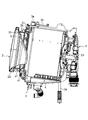
- FIG. 2 is a schematic cross-sectional view for explaining the configuration of the drum type washing machine.
- the drum type washing machine is attached to a bottomed cylindrical water tank 3 disposed in the outer box 1, a bottomed cylindrical drum 4 rotatably disposed in the water tank 3, and a rear part of the water tank 3.
- the motor 5 is provided.
- the drum 4 is an example of a rotating tank.
- a water supply pipe 13 is provided in the outer box 1.
- One end of the water supply pipe 13 has a water supply port 14 and is connected to a water tap (water faucet) through a hose (not shown).
- the other end of the water supply pipe 13 is divided into two forks.
- One of the two forks is connected to the water supply nozzle 6 via the first water supply valve 15 and the first water supply hose 17.
- the other of the two forks is connected to a detergent case (not shown) via the second water supply valve 16 and the second water supply hose 18.
- the tap water flowing into the detergent case is supplied between the water tank 3 and the drum 4 through a hose (not shown) after containing the detergent or softening agent in the detergent case.
- a hose made of relatively soft rubber or vinyl chloride is used as the first and second water supply hoses 17 and 18, for example.
- illustration of the water supply port 14 is abbreviate
- the door 2 has a glass window 21 and a resin frame 22 attached to the peripheral edge of the glass window 21.
- the frame body 22 is provided with a handle that is gripped by the user.
- the water tank 3 is inclined so that the rear part is lower than the front part.
- the water tank 3 has a water tank opening 31 that faces the outer box opening 11.
- a water supply nozzle 6 and an annular rubber packing 32 (shown in FIG. 3) are attached to the water tank opening 31.
- the front portion of the glass window 21 of the door 2 is in close contact with the inner peripheral edge of the packing 32.
- the washing water in the water tank 3 is prevented from leaking out of the water tank 3.
- the rear part of the glass window 21 of the door 2 enters the drum 4 and overlaps the tap water injection area of the water supply nozzle 6.
- the washing water is water containing a detergent or softening agent or water not containing a detergent or softening agent.
- the drum 4 is inclined so that the rear part is lower than the front part, like the water tank 3. Further, a drum opening 41 facing the water tank opening 31 is provided on the front surface of the drum 4. In addition, a plurality of through holes 42 (only three are shown in FIG. 2) are provided on the peripheral wall of the drum 4 throughout.
- the drum 4 accommodates the laundry 43.
- the drum opening 41 is an example of a rotating tank opening.
- the through hole 42 circulates washing water and air between the space between the water tank 3 and the drum 4 and the space inside the drum 4. For example, when the drum 4 is rotated in order to dehydrate the laundry 43 in the drum 4, the washing water in the drum 4 goes out of the drum 4 through the through hole 42.
- the motor 5 is an inverter motor, for example, and has a rotating shaft 51.
- the rotating shaft 51 is inclined with respect to the horizontal plane, and the tip is fixed to the center of the rear surface of the drum 4.
- FIG. 3 is a perspective view of the water tank 3 and its peripheral part.
- FIG. 4 is a schematic sectional view of the water tank 3 and its peripheral part.
- the water tank 3 is composed of a cylindrical water tank front part 3a provided with a water tank opening 31 and a bottomed cylindrical water tank rear part 3b.
- the front end portion of the water tank rear portion 3b is fixed to the rear end portion of the water tank front portion 3a.
- the water tank rear portion 3b is elastically supported by suspensions 7A and 7B.
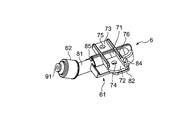
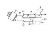
- FIG. 5 is a perspective view showing the external appearance of the water supply nozzle 6.
- FIG. 6 is a perspective view showing a state in which the water supply nozzle 6 is disassembled.
- the water supply nozzle 6 includes a nozzle body 61, a cap 62 attached to the downstream end of the nozzle body 61, and a swirler 63 that generates a swirling flow. ing.
- the nozzle body 61 has a first nozzle pipe 71 and a second nozzle pipe 81 assembled to the first nozzle pipe 71.
- the first nozzle pipe 71 is provided with plate-like first and second attachment portions 72 and 73 attached to the water tank opening 31 with screws.
- the first and second attachment portions 72 and 73 have through holes 74 and 75 through which screws are inserted.
- a plate-like stepped rib 76 is erected on the upper surface of the first mounting portion 72 in the drawing.
- the second nozzle pipe 81 is provided with a plate-like attachment portion 82 attached to the water tank opening 31.
- the attachment portion 82 has a through hole 83 through which a screw is inserted.
- a hook portion 84 is erected on the upper surface of the mounting portion 82 in the drawing.
- the hook portion 84 is releasably locked to a relatively low portion of the stepped rib 76.
- a triangular prism-shaped protrusion 85 protruding outward in the radial direction is provided upright at the upstream end of the outer peripheral surface of the second nozzle tube 81.
- the protrusion 85 abuts on the downstream end surface of the first nozzle tube 71.
- An annular first rib 86 and an annular second rib 87 positioned downstream of the first rib 86 are provided at the downstream end of the outer peripheral surface of the second nozzle pipe 81. ing.
- the first rib 86 contacts the upstream end surface of the cap 62 to position the cap 62.
- the second rib 87 bites into the inner peripheral surface of the cap 62 and makes it difficult to remove the cap 62 from the second nozzle tube 81.
- the cap 62 is made of an elastic material (for example, rubber).
- an injection port 91 is provided at the distal end surface of the cap 62, and tap water from the nozzle body 61 side passes through the injection port.
- the swirler 63 is rotatably accommodated in the downstream end portion of the second nozzle pipe 81. Moreover, the swirler 63 has two substantially semicircular disk-shaped portions 101 and 102 that change the flow of tap water, and has a substantially X-shaped cross section.
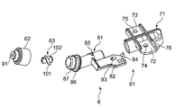
- FIG. 7 is a perspective view showing an appearance viewed from the side opposite to FIG. Moreover, FIG. 8 is the figure which looked at the water supply nozzle 6 from the side.
- the upstream end of the nozzle body 61 (the upstream end of the first nozzle pipe 71) surrounds the inner cylinder 111 and the inner cylinder 111 as shown in FIGS. And an outer cylinder portion 112.
- the axial length of the inner cylindrical portion 111 is longer than the axial length of the outer cylindrical portion 112.
- the inner cylinder portion 111 is provided with a notch 113 for demarcating an inlet of tap water.
- the outer cylinder part 112 is provided with a notch 114 for determining the position of the notch 113 with respect to the water tank opening 31.
- the outer cylinder portion 112 has a predetermined annular gap with the inner cylinder portion 111, and an annular packing 115 (shown in FIG. 9) is disposed in the gap.
- the inner cylinder part 111 is an example of a cylinder part.
- the inner cylinder portion 111 has a longer axial length than the outer cylinder portion 112, the center of the packing 115 is not greatly deviated from the central axis of the inner cylinder portion 111. That is, the sealing performance of the packing 115 can be maintained satisfactorily.
- a triangular prism-shaped protrusion 88 is erected on the upstream end of the outer peripheral surface of the second nozzle tube 81 so as to face the protrusion 85 in the radial direction.
- the protruding portion 85 protrudes in the opposite direction to the protruding portion 85. Further, the protrusion 85 does not contact the end face on the downstream side of the first nozzle tube 71 but contacts the plate-like rib 121 (shown in FIG. 12) provided in the water tank opening 31.
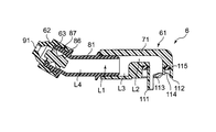
- FIG. 9 is a cross-sectional view of the water supply nozzle 6 as viewed from the side.
- the nozzle body 61 is provided with a flow path L1 through which tap water flows.
- a swirler 63 is disposed at the downstream end of the flow path L1.
- the flow path L1 has a throttle portion L2 and first and second widened portions L3 and L4.
- the throttle portion L2 is provided on the upstream side of the swirler 63.
- the first and second spreading portions L3 and L4 are provided on the downstream side of the throttle portion L2 and on the upstream side of the swirler 63. Further, the first and second spreading portions L3 and L4 each have a channel cross-sectional area larger than the channel cross-sectional area of the throttle portion L2.
- flow path cross-sectional area of the second expanded portion L4 Is set to 38.5 mm 2 .
- the tap water is an example of water.
- a part of the flow path L1 is provided in the first nozzle tube 71.
- the remainder of the flow path L1 is provided in the second nozzle pipe 81. That is, the flow path L ⁇ b> 1 includes a flow path in the first nozzle pipe 71 and a flow path in the second nozzle pipe 81.
- the upstream end portion of the second nozzle tube 81 is loosely fitted in the downstream end portion of the first nozzle tube 71.
- the upstream end of the second nozzle tube 81 is in the downstream end of the first nozzle tube 71, and the inner peripheral surface of the downstream end of the first nozzle tube 71 A gap is formed between the outer peripheral surface of the upstream end portion of the second nozzle pipe 81.
- the difference between the diameter of the inner peripheral surface of the downstream end of the first nozzle tube 71 and the diameter of the outer peripheral surface of the upstream end of the second nozzle tube 81 is set to, for example, 0.5 mm or less. Is done.
- the cross-sectional area of the flow path gradually decreases from the inlet defined by the notch 113 to the throttle portion L2.
- the flow path cross-sectional area of the throttle portion L2 is set to 16.6 mm 2
- the flow path cross-sectional area of the inlet is set to 78.5 mm 2 and the flow in the region between the inlet and the throttle portion L2 is set.
- the road cross-sectional area is set to 33.2 mm 2 .
- the channel cross-sectional area in the region between the inlet and the throttle portion L2 is a value obtained by reducing the channel cross-sectional area of the inlet by 1/3 or more of the channel cross-sectional area of the inlet. .
- the flow path cross-sectional area of the throttle portion L2 is also 1/3 or more of the flow path cross-sectional area of the region between the inlet and the throttle portion L2 from the flow channel cross-sectional area of the region between the inlet and the throttle portion L2. The value has decreased. That is, the amount of change in the cross-sectional area of the channel is 1/3 or more.
- the cross-sectional area of the flow path gradually decreases from the first spreading portion L3 to the injection port 91.
- the flow path cross-sectional area of 78.5 mm 2 of the second expanded portion L3, L4 when setting the 38.5 mm 2, 11.1 mm the flow path cross-sectional area of the flow passage swirl member 63 is disposed 2 and the flow passage cross-sectional area of the injection port 91 is set to 7.1 mm 2 .
- the flow path cross-sectional area of the region where the swirler 63 is disposed is a value obtained by reducing the flow path cross-sectional area of the second widened portion L4 by 1 ⁇ 4 or more of the flow path cross-sectional area of the second widened portion L4. ing.
- the flow passage cross-sectional area of the injection port 91 is also a value obtained by reducing the flow passage cross-sectional area of the region where the swirler 63 is disposed by 1/3 or more of the flow passage cross-sectional area of the region where the swirler 63 is disposed. ing. That is, the amount of change in the cross-sectional area of the channel is 1/3 or more.
- the direction of the tap water is changed several times. More specifically, when the tap water flows into the flow path L1 from the inflow port defined by the notch 113, the direction of flowing twice is changed and reaches the throttle portion L2. And the said tap water flows into the injection port 91, changing the direction of a flow, after flowing from the throttle part L2 to the 2nd spreading part L4 in the substantially linear form.
- the distance of the section in which this tap water flows substantially linearly is determined by, for example, a ratio to the diameter of the throttle portion L2.
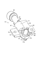
- FIG. 10 is a perspective view for explaining the attachment of the water supply nozzle 6.
- An annular resin packing cover 33 is attached to the water tank opening 31 so as to be positioned behind the packing 32.
- the water supply nozzle 6 is attached to the water tank opening 31 so that a part of the water supply nozzle 6 overlaps the packing cover 33.
- a cylindrical connection portion 131 is provided in the water tank opening 31.
- the inner tube portion 111 of the water supply nozzle 6 is inserted into the connection portion 131 and the outer tube portion 112 of the water supply nozzle 6 is fitted onto the connection portion 131.
- the inner cylinder part 111 since the inner cylinder part 111 has a longer axial length than the outer cylinder part 112, the inner cylinder part 111 functions as a guide for guiding the outer cylinder part 112 of the water supply nozzle 6 to the connection part 131.
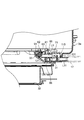
- FIG. 11 is a view of the main part of the water tank front 3a as seen from the rear.
- FIG. 12 is a sectional view taken along line XII-XII in FIG.
- the packing cover 33 comes into contact with the front end surface of the cap 62 as shown in FIGS. At this time, the packing cover 33 contacts a part of the outer peripheral surface of the cap 62.
- the packing cover 33 is an example of a contact portion.
- the water tank front part 3 a is provided with a water supply path L ⁇ b> 11 communicating with the first water supply hose 17.
- the flow path L1 communicates with the water supply path L11 through the connection portion 131.
- the water supply path L11 extends in a direction intersecting the axial direction of the inner cylinder portion 111.
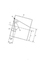
- FIG. 13 is a schematic diagram for explaining a tap water injection region of the water supply nozzle 6.
- the water supply nozzle 6 injects tap water
- tap water hits a portion above the point where the rear end portion of the drum 4 and the rotation axis J of the drum 4 intersect. More specifically, the length X of the longest portion of the rear end portion of the drum 4 where the tap water hits is longer than the inner radius r of the drum 4.
- the length Y1 from the front end portion of the drum 4 to the rearmost end of the glass window 21 is the length between the longest portion of the inner peripheral surface of the drum 4 where tap water hits and the front end portion of the drum 4. It is longer than Y2.
- ⁇ in FIG. 13 is an angle formed by the central axis of the tap water injection region of the water supply nozzle 6 and the front end of the drum 4.
- ⁇ 1 and ⁇ 2 are angles corresponding to 1 ⁇ 2 of the tap water injection angle of the water supply nozzle 6, respectively.
- the tap water flows through the flow path L1 of the nozzle body 61.
- the tap water passes through the throttle portion L2 in the nozzle main body 61, high water pressure water can flow downstream from the throttle portion L2.
- the first and second widened portions L3 and L4 having a channel cross-sectional area larger than the channel cross-sectional area of the throttle portion L2 are provided. Is provided.
- the tap water spray output of the water supply nozzle 6 can be increased, and the tap water injection angle can be increased. . Therefore, the tap water sprayed by the water supply nozzle 6 can be strongly applied to the laundry 43 and the tap water can be expanded.
- the tap water flows in a substantially straight line from the throttle portion L2 to the second spreading portion L4, it is possible to arrange the disturbance of the tap water flow. Therefore, the pressure loss due to the disturbance of the tap water flow can be reduced.
- the tap water sprayed by the water supply nozzle 6 can be strongly applied to the laundry 43 and the tap water can be expanded, the effect of removing the washing water and dirt remaining on the laundry 43 is enhanced. be able to.
- the cap 62 is made of an elastic material and thus elastically deforms. As a result, a gap is generated between the downstream end of the nozzle body 61 and the cap 62. Therefore, the state where the tap water is appropriately discharged from the gap and the water pressure in the water supply nozzle 6 is an abnormal value can be solved.
- the tap water supply nozzle 6 is attached to the water tank opening 31, even if the tap water leaks from the gap between the downstream end of the nozzle body 61 and the cap 62, the tap water is supplied to the water tank 3. Can be stored inside. Therefore, the tap water can be prevented from leaking out of the water tank 3.
- the packing cover 33 comes into contact with the front end surface of the cap 62, so that the cap 62 can be prevented from falling off.
- the cap 62 may rotate with the laundry 43 and damage the laundry 43. Therefore, by preventing the cap 62 from falling off, the risk of the laundry 43 being damaged can be reduced.
- the upstream end of the second nozzle tube 81 is loosely fitted in the downstream end of the first nozzle tube 71, the inner peripheral surface of the downstream end of the first nozzle tube 71 and A gap is formed between the outer peripheral surface of the upstream end portion of the second nozzle pipe 81. Therefore, since water can be discharged appropriately from the gap, it is possible to prevent the water pressure in the water supply nozzle 6 from becoming excessively high.
- the water supply nozzle 6 is attached to the water tank opening 31, the gap between the inner peripheral surface of the downstream end portion of the first nozzle pipe 71 and the outer peripheral surface of the upstream end portion of the second nozzle pipe 81. Even if the tap water leaks from the gap, the tap water can be stored in the water tank 3. Therefore, the tap water can be prevented from leaking out of the water tank 3.
- the upstream end portion of the nozzle body 61 has an inner cylinder portion 111 provided with a notch 113 for defining an inlet of tap water to the flow path L1. Accordingly, an appropriate amount of tap water can be flowed from the water supply path L11 extending in the direction intersecting the axial direction of the inner cylinder portion 111 to the flow path L1 of the nozzle body 61 through the notch 113.
- the rear part of the glass window 21 of the door 2 enters the drum 4 and overlaps the tap water injection area of the water supply nozzle 6.
- lint can be washed away with tap water.
- the glass window 21 can be washed by the tap water sprayed by the water supply nozzle 6, it is not necessary to provide a nozzle for blowing water for washing the glass window 21 in addition to the water supply nozzle 6. Therefore, the number of parts can be reduced, and a cost reduction effect can be obtained.
- the length X of the longest portion of the rear end portion of the drum 4 where the tap water hits is longer than the inner radius r of the drum 4, so that the tap water is poured over a wide area of the laundry 43. Can do.
- the drum type washing machine of the first embodiment may have a drying function or may not have a drying function.
- the drying method may be, for example, a heater drying method that generates warm air using a sheathed heater, or a heat pump drying method that generates hot air using a heat pump. It may be.
- the water supply nozzle 6 is used in the drum type washing machine, but it may be used in a so-called vertical washing machine such as a fully automatic washing machine.
- tap water is supplied to the water supply nozzle 6, but bath water may be supplied to the water supply nozzle 6 by connecting a bath water pump to the water supply port 14 via a hose.
- the water supply nozzle 6 sprays water that does not contain detergent and softener, but tap water or bath water is supplied to the water supply nozzle 6 via the detergent case, You may make it spray the water containing a detergent or a softening agent.
- the water supply nozzle 6 may be attached to a place other than the water tank opening 31 (for example, the outer box opening 11).
- the flow of the throttle portion L2 is changed between the throttle portion L2 and the swirler 63 instead of the first and second widened portions L3 and L4.
- One spreading portion having a channel cross-sectional area smaller than the channel cross-sectional area is provided.
- the washing machine of this invention An outer box 1 having an outer box opening 11; A water tank 3 disposed in the outer box 1 and having a water tank opening 31 facing the outer box opening 11; A rotating tank 4 that is rotatably arranged in the water tank 3 and has a rotating tank opening 41 facing the water tank opening 31; A water supply nozzle 6 for supplying water into the rotating tank 4;
- the water supply nozzle 6 is A nozzle body 61 provided with a flow path L1 through which water flows;
- a swirler 63 disposed in the flow path L1 and generating a swirling flow;
- the flow path L1 is A throttle portion L2 provided on the upstream side of the swirler 63; There are widened portions L3 and L4 that are provided downstream of the throttle portion L2 and upstream of the swirler 63 and have a channel cross-sectional area larger than that of the throttle portion L2. It is characterized by that.
- the water supply nozzle 6 is attached to an end portion on the downstream side of the nozzle body 61 and has a cap 62 provided with an injection port 91 through which water from the nozzle body 61 passes.
- the cap 62 is made of an elastic material.
- the cap 62 when the injection port 91 is blocked with, for example, lint, and the water pressure in the water supply nozzle 6 becomes an abnormal value, the cap 62 is made of an elastic material and thus elastically deforms. As a result, a gap is generated between the downstream end of the nozzle body 61 and the cap 62. Therefore, the state in which water is appropriately discharged from the gap and the water pressure in the water supply nozzle 6 is an abnormal value can be solved.
- the water tank 3 is provided with an abutting portion 33 that abuts against the tip surface of the cap 62.
- the contact portion 33 contacts the front end surface of the cap 62, so that the cap 62 falls off. Can be prevented.
- the nozzle body 61 is A first nozzle tube 71; A second nozzle pipe 81 assembled to the first nozzle pipe 71, One end of the second nozzle tube 81 is loosely fitted in one end of the first nozzle tube 71.
- the one end portion of the second nozzle tube 81 is loosely fitted in the one end portion of the first nozzle tube 71, the inner peripheral surface of the one end portion of the first nozzle tube 71 and the second nozzle tube.
- a gap is formed between the outer peripheral surface of one end portion of 81.
- the upstream end of the nozzle body 61 has a cylindrical portion 111 provided with a notch 113 for defining a water inlet to the flow path L1.
- the upstream end portion of the nozzle body 61 has the cylindrical portion 111 provided with the notch 113 for defining the water inlet to the flow path L1. Accordingly, an appropriate amount of water can be flowed from the flow path L1 flowing in the direction intersecting the axial direction of the cylindrical portion 111 to the flow path L1 of the nozzle body 61 through the notch 113. That is, a large amount of water can be supplied to the flow path L1 of the nozzle body 61.
- the washing machine of one embodiment is A door 2 attached to the outer box 1 for opening and closing the outer box opening 11; When the door 2 closes the outer box opening 11, a part of the door 2 enters the rotating tub 4 and overlaps the water injection region of the water supply nozzle 6.
Abstract
洗濯機は、回転槽内に水を供給する給水ノズル(6)を備える。給水ノズル(6)は、水が流れる流路(L1)が設けられたノズル本体(61)と、流路L1に配置され、旋回流を発生させる旋回子(63)とを有する。流路(L1)は、旋回子(63)よりも上流側に設けられた絞り部(L2)と、絞り部(L2)よりも下流側、かつ、旋回子(63)よりも上流側に設けられて、絞り部(L2)の流路断面積よりも大きな流路断面積を有する広がり部(L3,L4)とを持つ。
Description
この発明は洗濯機に関する。
従来、洗濯機としては、特表2013-509281号公報(特許文献1)に開示されているように、ドラム内に洗濯水を供給する給水ノズルを備えた洗濯機がある。より詳しくは、上記給水ノズルは、洗濯水を噴射し、この洗濯水で渦流を生成する。これにより、上記洗濯水が細分化されて、洗濯水が洗濯物に早く吸収される。
ところが、上記従来の洗濯機では、給水ノズルから噴射される洗濯水を洗濯物に強く当てようとすると、その洗濯水が広がらなくなってしまう。一方、上記給水ノズルから噴射される洗濯水を広げようとすると、洗濯物に上記洗濯水を強く当てることができなくなってしまう。
したがって、上記従来の洗濯機には、給水ノズルが噴射した洗濯水を洗濯物に強く当てると共に、その洗濯水を広げることができないという問題がある。
そこで、この発明の課題は、給水ノズルが噴射した水を洗濯物に強く当てることができ、かつ、その水を広げることができる洗濯機を提供することにある。
上記課題を解決するため、この発明の洗濯機は、
外箱開口部を有する外箱と、
上記外箱内に配置されて、上記外箱開口部に対向する水槽開口部を有する水槽と、
上記水槽内に回転可能に配置されて、上記水槽開口部に対向する回転槽開口部を有する回転槽と、
上記回転槽内に水を供給する給水ノズルと
を備え、
上記給水ノズルは、
水が流れる流路が設けられたノズル本体と、
上記流路に配置され、旋回流を発生させる旋回子と
を有し、
上記流路は、
上記旋回子よりも上流側に設けられた絞り部と、
上記絞り部よりも下流側、かつ、上記旋回子よりも上流側に設けられて、上記絞り部の流路断面積よりも大きな流路断面積を有する広がり部と
を持つことを特徴としている。
外箱開口部を有する外箱と、
上記外箱内に配置されて、上記外箱開口部に対向する水槽開口部を有する水槽と、
上記水槽内に回転可能に配置されて、上記水槽開口部に対向する回転槽開口部を有する回転槽と、
上記回転槽内に水を供給する給水ノズルと
を備え、
上記給水ノズルは、
水が流れる流路が設けられたノズル本体と、
上記流路に配置され、旋回流を発生させる旋回子と
を有し、
上記流路は、
上記旋回子よりも上流側に設けられた絞り部と、
上記絞り部よりも下流側、かつ、上記旋回子よりも上流側に設けられて、上記絞り部の流路断面積よりも大きな流路断面積を有する広がり部と
を持つことを特徴としている。
一実施形態の洗濯機では、
上記給水ノズルは、上記ノズル本体の下流側の端部に取り付けられると共に、上記ノズル本体側からの水が通過する噴射口が設けられたキャップを有し、
上記キャップは弾性材から成る。
上記給水ノズルは、上記ノズル本体の下流側の端部に取り付けられると共に、上記ノズル本体側からの水が通過する噴射口が設けられたキャップを有し、
上記キャップは弾性材から成る。
一実施形態の洗濯機では、
上記水槽には、上記キャップの先端面に当接する当接部が設けられている。
上記水槽には、上記キャップの先端面に当接する当接部が設けられている。
一実施形態の洗濯機では、
上記ノズル本体は、
第1ノズル管と、
上記第1ノズル管に組み付けられた第2ノズル管と
を有し、
上記第1ノズル管の一端部内に上記第2ノズル管の一端部を遊嵌させている。
上記ノズル本体は、
第1ノズル管と、
上記第1ノズル管に組み付けられた第2ノズル管と
を有し、
上記第1ノズル管の一端部内に上記第2ノズル管の一端部を遊嵌させている。
一実施形態の洗濯機では、
上記ノズル本体の上流側の端部は、上記流路への水の流入口を画定するための切り欠きが設けられた筒部を有している。
上記ノズル本体の上流側の端部は、上記流路への水の流入口を画定するための切り欠きが設けられた筒部を有している。
一実施形態の洗濯機は、
上記外箱に取り付けられて上記外箱開口部を開閉するドアを備え、
上記ドアは、上記外箱開口部を閉鎖すると、一部が上記回転槽内に入って上記給水ノズルの水の噴射領域と重なる。
上記外箱に取り付けられて上記外箱開口部を開閉するドアを備え、
上記ドアは、上記外箱開口部を閉鎖すると、一部が上記回転槽内に入って上記給水ノズルの水の噴射領域と重なる。
この発明の洗濯機によれば、給水ノズルは、水が流れる流路が設けられたノズル本体と、この流路に配置され、旋回流を発生させる旋回子とを有する。そして、上記流路は、旋回子よりも上流側に設けられた絞り部と、絞り部よりも下流側、かつ、旋回子よりも上流側に設けられて、絞り部の流路断面積よりも大きな流路断面積を有する広がり部とを持つ。これにより、上記旋回子に高水圧の水を多量に流すことができるので、給水ノズルの水の噴出力を高かめることができ、かつ、その水の噴射角を大きくすることができる。したがって、上記給水ノズルが噴射した水を洗濯物に強く当てることができ、かつ、その水を広げることができる。
以下、この発明の洗濯機を図示の実施の形態により詳細に説明する。
〔第1実施形態〕
図1は、この発明の第1実施形態の洗濯機の一例としてのドラム式洗濯機の外観を示す概略斜視図である。
図1は、この発明の第1実施形態の洗濯機の一例としてのドラム式洗濯機の外観を示す概略斜視図である。
上記ドラム式洗濯機は、外箱開口部11を前面部に有する外箱1を備えている。この外箱1の前面部には、外箱開口部11を開閉するドア2をヒンジで左右方向に回動可能に取り付けられている。また、外箱1の前面部の上部には操作表示部12が設けられている。ユーザは、操作表示部12を操作することにより、所望の洗濯コースを選択する。また、操作表示部12は例えば洗濯コースの残り時間などを表示する。
図2は上記ドラム式洗濯機の構成を説明するための模式断面図である。
上記ドラム式洗濯機は、外箱1内に配置された有底筒形状の水槽3と、この水槽3内に回転可能に配置された有底円筒形状のドラム4と、水槽3の後部に取り付けられたモータ5とを備えている。なお、ドラム4は回転槽の一例である。
上記外箱1内には給水管13が設けられている。この給水管13の一端部は、給水口14を有し、図示しないホースを介して水道蛇口(水栓)に接続される。一方、給水管13の他端部は2股に分かれている。この2股の一方は、第1給水弁15および第1給水ホース17を介して給水ノズル6に接続されている。また、上記2股の他方は、第2給水弁16および第2給水ホース18を介して、図示しない洗剤ケースに接続されている。この洗剤ケースに流入した水道水は、洗剤ケース内の洗剤または柔軟剤を含んだ後、図示しないホースを介して、水槽3とドラム4の間に供給されるようになっている。なお、第1,第2給水ホース17,18としては、例えば、比較的柔らかいゴムまたは塩化ビニールからなるホースが用いられる。また、図1では給水口14の図示を省略している。
上記ドア2は、ガラス窓21と、このガラス窓21の周縁部に取り付けられた樹脂製の枠体22とを有している。この枠体22には、ユーザが掴む把手が設けられている。
上記水槽3は、後部が前部より下がるように傾いている。また、水槽3は、外箱開口部11に対向する水槽開口部31を有している。この水槽開口部31には、給水ノズル6と、環状のゴム製のパッキン32(図3に示す)とが取り付けられている。ドア2が外箱開口部11を閉鎖したとき、ドア2のガラス窓21の前部がパッキン32の内周縁部に密着する。これにより、水槽3内の洗濯水が水槽3外に漏れ出ないようになっている。また、ドア2が外箱開口部11を閉鎖すると、ドア2のガラス窓21の後部がドラム4内に入って給水ノズル6の水道水の噴射領域と重なる。なお、上記洗濯水とは、洗剤もしくは柔軟剤等を含む水、または、洗剤もしくは柔軟剤などを含まない水である。
上記ドラム4は、水槽3と同様に、後部が前部より下がるように傾いている。また、ドラム4の前面部には、水槽開口部31に対向するドラム開口部41が設けられている。また、ドラム4の周壁には複数の貫通穴42(図2では3個のみ図示する)が全体に渡って設けられている。また、ドラム4は洗濯物43を収容する。なお、ドラム開口部41は回転槽開口部の一例である。
上記貫通穴42は、水槽3とドラム4との間の空間と、ドラム4内の空間との間で洗濯水や空気を流通させる。例えば、ドラム4内の洗濯物43を脱水するためにドラム4を回転させると、ドラム4内の洗濯水が貫通穴42を通ってドラム4外に出る。
上記モータ5は、例えばインバータモータからなり、回転軸51を有する。この回転軸51は、水平面に対して傾斜し、先端部がドラム4の後面部の中央に固定されている。
図3は水槽3およびその周辺部の斜視図である。また、図4は水槽3およびその周辺部の概略断面図である。
上記水槽3は、図3,図4に示すように、水槽開口部31が設けられた筒形状の水槽前部3aと、有底筒形状の水槽後部3bとから成っている。この水槽後部3bの前端部は水槽前部3aの後端部に固定される。また、水槽後部3bはサスペンション7A,7Bによって弾性支持されている。
図5は、給水ノズル6の外観を示す斜視図である。また、図6は、給水ノズル6の分解した状態を示す斜視図である。
上記給水ノズル6は、図5,図6に示すように、ノズル本体61と、このノズル本体61の下流側の端部に取り付けられたキャップ62と、旋回流を発生させる旋回子63とを備えている。
上記ノズル本体61は、第1ノズル管71と、この第1ノズル管71に組み付けられた第2ノズル管81とを有している。
上記第1ノズル管71には、水槽開口部31にネジで取り付けられる板状の第1,第2取付部72,73が設けられている。この第1,第2取付部72,73は、ネジが挿通される貫通穴74,75を有している。また、第1取付部72の図中上側の表面には板状の段付きリブ76が立設されている。
上記第2ノズル管81には、水槽開口部31に取り付けられる板状の取付部82が設けられている。この取付部82は、ネジが挿通される貫通穴83を有する。第1ノズル管71に第2ノズル管81を組み付けたとき、取付部82の貫通穴83が第1取付部72の貫通穴74と重なる。これにより、第1取付部72の貫通穴74にネジを挿通すると、このネジが取付部82の貫通穴83にも挿通される。
また、上記取付部82の図中上側の表面にはフック部84が立設されている。第1ノズル管71に第2ノズル管81を組み付けたとき、フック部84が段付きリブ76の比較的低い部分に解除可能に係止する。
また、上記第2ノズル管81の外周面の上流側の端部には、径方向外側に突出する三角柱形状の突起部85が立設されている。第1ノズル管71に第2ノズル管81を組み付けたとき、突起部85が第1ノズル管71の下流側の端面に当接する。
また、上記第2ノズル管81の外周面の下流側の端部には、環状の第1リブ86と、この第1リブ86よりも下流側に位置する環状の第2リブ87とが設けられている。この第1リブ86は、キャップ62の上流側の端面に当接して、キャップ62を位置決めする。一方、第2リブ87は、キャップ62の内周面に食い込んで、第2ノズル管81からキャップ62を外れ難くする。
上記キャップ62は弾性材(例えばゴム)から成っている。また、キャップ62の先端面には噴射口91が設けられ、ノズル本体61側からの水道水が噴射口を通過する。
上記旋回子63は、第2ノズル管81の下流側の端部内に回転可能に収容されている。また、旋回子63は、水道水の流れを変更する略半円板形状の2つの部分101,102を有して、断面形状が略X字形状を呈する。
図7は、図5とは反対側から見た外観を示す斜視図である。また、図8は、給水ノズル6を側方から見た図である。
また、上記ノズル本体61の上流側の端部(第1ノズル管71の上流側の端部)は、図7,図8に示すように、内筒部111と、この内筒部111を取り囲む外筒部112とを有している。この内筒部111の軸方向の長さは外筒部112の軸方向の長さよりも長くなっている。また、内筒部111には、水道水の流入口を画定するための切り欠き113が設けられている。一方、外筒部112には、水槽開口部31に対する切り欠き113の位置を決めるための切り欠き114が設けられている。また、外筒部112は内筒部111との間に所定の環状の隙間を有し、環状のパッキン115(図9に示す)が上記隙間に配置される。なお、内筒部111は筒部の一例である。
また、上記内筒部111は外筒部112に比べて軸方向の長さが長いので、パッキン115の中心が内筒部111の中心軸から大きく外れないようになっている。すなわち、パッキン115のシール性能を良好に維持できるようになっている。
また、上記第2ノズル管81の外周面の上流側の端部には、径方向において突起部85と対向するように三角柱形状の突起部88が立設されている。この突起部85は、突起部85とは逆方向に突出する。また、突起部85は、第1ノズル管71の下流側の端面に当接しないが、水槽開口部31に設けられた板状のリブ121(図12に示す)に当接する。
図9は、給水ノズル6を側方から見た断面を示す図である。
上記ノズル本体61には、水道水が流れる流路L1が設けられている。その流路L1の下流側の端部には旋回子63が配置されている。この流路L1は絞り部L2および第1,第2広がり部L3,L4を持つ。この絞り部L2は旋回子63よりも上流側に設けられている。一方、第1,第2広がり部L3,L4は、絞り部L2よりも下流側、かつ、旋回子63よりも上流側に設けられている。また、第1,第2広がり部L3,L4は、それぞれ、絞り部L2の流路断面積よりも大きな流路断面積を有している。例えば、絞り部L2の流路断面積を16.6mm2に設定する場合、第1広がり部L3の流路断面積を78.5mm2に設定すると共に、第2広がり部L4の流路断面積を38.5mm2に設定する。なお、上記水道水は水の一例である。
また、上記流路L1の一部は第1ノズル管71に設けられている。そして、流路L1の残りが第2ノズル管81に設けられている。すなわち、流路L1は、第1ノズル管71内の流路と、第2ノズル管81内の流路とから成っている。
また、上記第2ノズル管81の上流側の端部が第1ノズル管71の下流側の端部内に遊嵌している。別の言い方をすると、第2ノズル管81の上流側の端部が第1ノズル管71の下流側の端部内に入っており、第1ノズル管71の下流側の端部の内周面と、第2ノズル管81の上流側の端部の外周面との間に隙間が生じている。このとき、第1ノズル管71の下流側の端部の内周面の径と、第2ノズル管81の上流側の端部の外周面の径との差が、例えば0.5mm以下に設定される。
また、上記給水ノズル6の流路L1では、切り欠き113で画定された流入口から絞り部L2まで、流路断面積が段階的に減少する。例えば、絞り部L2の流路断面積を16.6mm2に設定する場合、上記流入口の流路断面積78.5mm2に設定する共に、上記流入口と絞り部L2の間の領域の流路断面積33.2mm2に設定する。この場合、上記流入口と絞り部L2の間の領域の流路断面積は、上記流入口の流路断面積から、流入口の流路断面積の1/3以上減った値になっている。また、絞り部L2の流路断面積も、流入口と絞り部L2の間の領域の流路断面積から、上記流入口と絞り部L2の間の領域の流路断面積の1/3以上減った値になっている。すなわち、流路断面積の変化量は1/3以上になっている。
また、上記給水ノズル6の流路L1では、第1広がり部L3から噴射口91まで、流路断面積が段階的に減少する。例えば、第1,第2広がり部L3,L4の流路断面積を78.5mm2, 38.5mm2に設定する場合、旋回子63が配置された流路の流路断面積を11.1mm2に設定すると共に、噴射口91の流路断面積を7.1mm2に設定する。この場合、旋回子63が配置された領域の流路断面積は、第2広がり部L4の流路断面積から、第2広がり部L4の流路断面積の1/4以上減った値になっている。また、噴射口91の流路断面積も、旋回子63が配置された領域の流路断面積から、旋回子63が配置された領域の流路断面積の1/3以上減った値になっている。すなわち、流路断面積の変化量は1/3以上になっている。なお、旋回子63が配置された領域の流路断面積とは、旋回子63の回転軸に垂直な面が旋回子63の回転軸方向の中央を通るとき、その面において水道水が通過する部分の面積に相当する。
また、上記給水ノズル6内では、水道水は複数回流れの向きを変える。より詳しくは、上記水道水は、切り欠き113で画定された流入口から流路L1内に流入すると、2回流れる向きを変えて、絞り部L2に到達する。そして、上記水道水は、絞り部L2から第2広がり部L4まで略直線状に流れた後、流れの向きを変えて、噴射口91へ流れる。この水道水が略直線状に流れる区間の距離は、例えば、絞り部L2の径に対する比で決定される。
図10は給水ノズル6の取り付けを説明するための斜視図である。
上記水槽開口部31には、パッキン32の後方に位置するように環状の樹脂製のパッキンカバー33が取り付けられている。このパッキンカバー33に給水ノズル6の一部が重なるように、水槽開口部31に給水ノズル6が取り付けられる。
また、上記水槽開口部31には筒形状の接続部131が設けられている。水槽開口部31に給水ノズル6が取り付けるとき、給水ノズル6の内筒部111を接続部131内に挿入すると共に、給水ノズル6の外筒部112を接続部131に外嵌させる。このとき、内筒部111は外筒部112に比べて軸方向の長さが長いので、給水ノズル6の外筒部112を接続部131に案内するガイドとして内筒部111が機能する。
図11は水槽前部3aの要部を後方から見た図である。また、図12は図11のXII-XII線から見た断面図である。
上記水槽開口部31に給水ノズル6を取り付けると、図11,図12に示すように、パッキンカバー33がキャップ62の先端面に当接する。このとき、パッキンカバー33は、キャップ62の外周面の一部に接触する。なお、パッキンカバー33は当接部の一例である。
また、上記水槽前部3aには、第1給水ホース17内に連通する給水路L11が設けられている。給水ノズル6の内筒部111を接続部131内に挿入すると、流路L1が接続部131内を介して給水路L11に連通する。この給水路L11は、内筒部111の軸方向に交差する方向に延びている。
図13は上記給水ノズル6の水道水の噴射領域を説明するための模式図である。
上記給水ノズル6が水道水を噴射するとき、ドラム4の後端部とドラム4の回転軸Jとが交わる点よりも上側の部分に水道水が当たる。より詳しくは、ドラム4の後端部において水道水が当たる部分で最も長い部分の長さXは、ドラム4の内半径rよりも長くなっている。
また、上記ドラム4の前端部からガラス窓21の最後端までの長さY1は、ドラム4の内周面において水道水が当たる部分で最も長い部分とドラム4の前端部との間の長さY2よりも長くなっている。
なお、図13のαは、給水ノズル6の水道水の噴射領域の中心軸が、ドラム4の前端部と成す角度である。また、β1,β2は、それぞれ、給水ノズル6の水道水の噴射角の1/2に相当する角度である。
上記構成のドラム式洗濯機によれば、給水ノズル6がドラム4内に向かって水道水を噴射するとき、水道水がノズル本体61の流路L1を流れる。このとき、ノズル本体61では、水道水が絞り部L2を通過するので、絞り部L2よりも下流側に高水圧の水を流すことができる。また、絞り部L2よりも下流側、かつ、旋回子63よりも上流側には、絞り部L2の流路断面積よりも大きな流路断面積を有する第1,第2広がり部L3,L4が設けられている。これにより、旋回子63に高水圧の水を多量に流すことができるので、給水ノズル6の水道水の噴出力を高かめることができ、かつ、その水道水の噴射角を大きくすることができる。したがって、給水ノズル6が噴射した水道水を洗濯物43に強く当てることができ、かつ、その水道水を広げることができる。
また、上記水道水は絞り部L2から第2広がり部L4まで略直線状に流れるので、水道水の流れの乱れを整えることができる。したがって、上記水道水の流れの乱れによる圧力損失を低減できる。
また、上記洗濯物43をすすぐ場合、ドラム4が回転している状態で、給水ノズル6に水道水を噴射させたとき、ドラム4の回転による遠心力と、水道水の水圧との作用で、洗濯物43に残った洗濯水や汚れを効果的に除去できる。
また、上記給水ノズル6が噴射した水道水を洗濯物43に強く当てることができ、かつ、その水道水を広げることができるので、洗濯物43に残った洗濯水や汚れを除去する効果を高めることができる。
また、上記噴射口91が例えば糸屑で閉塞されて、給水ノズル6内の水圧が異常値になった場合、キャップ62は、弾性材から成るので、弾性変形する。その結果、ノズル本体61の下流側の端部とキャップ62との間に隙間が生じる。したがって、上記隙間から水道水を適度に排出して、給水ノズル6内の水圧が異常値になっている状態を解消できる。
また、上記水槽開口部31に給水ノズル6を取り付けているので、ノズル本体61の下流側の端部とキャップ62との間の隙間から水道水が漏れ出たとしても、この水道水を水槽3内に溜めることができる。したがって、上記水道水が水槽3外に漏れ出るのを防ぐことができる。
また、上記給水ノズル6内の水圧が異常値になっている状態を解消できるので、異常に高くなった水圧の影響で第1給水ホース17が破損するのを防ぐことができる。
また、上記噴射口91が例えば糸屑で閉塞されて、給水ノズル6内の水圧が上がった場合、パッキンカバー33がキャップ62の先端面に当接するので、キャップ62の脱落を防ぐことができる。
上記キャップ62がノズル本体61の下流側の端部から脱落した場合、キャップ62が洗濯物43と一緒に回転して、洗濯物43を傷付ける恐れがある。したがって、上記キャップ62の脱落を防ぐことにより、洗濯物43に傷が付く恐れを低減できる。
また、上記第1ノズル管71の下流側の端部内に第2ノズル管81の上流側の端部を遊嵌させているので、第1ノズル管71の下流側の端部の内周面と第2ノズル管81の上流側の端部の外周面との間に隙間が生じる。したがって、上記隙間から水を適度に排出できるので、給水ノズル6内の水圧が過度に高くなるのを防ぐことができる。
また、上記水槽開口部31に給水ノズル6を取り付けているので、第1ノズル管71の下流側の端部の内周面と第2ノズル管81の上流側の端部の外周面との間の隙間から水道水が漏れ出たとしても、この水道水を水槽3内に溜めることができる。したがって、上記水道水が水槽3外に漏れ出るのを防ぐことができる。
また、上記ノズル本体61の上流側の端部は、流路L1への水道水の流入口を画定するための切り欠き113が設けられた内筒部111を有している。これにより、上記内筒部111の軸方向に交差する方向に延びる給水路L11から、切り欠き113を介してノズル本体61の流路L1に、適切な量の水道水を流すことができる。
また、上記ドア2が外箱開口部11を閉鎖すると、ドア2のガラス窓21の後部がドラム4内に入って給水ノズル6の水道水の噴射領域と重なるので、ガラス窓21の後部に付着した例えば糸屑を水道水で洗い流せる。
また、上記給水ノズル6が水道水を噴射することにより、ガラス窓21を洗浄できるので、給水ノズル6の他に、ガラス窓21を洗浄するための水を吹き出すノズルを設けなくてよい。したがって、部品点数を削減できるので、コストダウン効果が得られる。
また、上記ドラム4の後端部において水道水が当たる部分で最も長い部分の長さXは、ドラム4の内半径rよりも長くなっているので、洗濯物43の広範囲に水道水をかけることができる。
上記第1実施形態のドラム式洗濯機は、乾燥機能を有してもよいし、乾燥機能を有さなくてもよい。
上記第1実施形態のドラム式洗濯機が乾燥機能を有する場合、乾燥方式は、例えばシーズヒータで温風を生成するヒータ乾燥方式であってもよいし、ヒートポンプで温風を生成するヒートポンプ乾燥方式であってもよい。
上記第1実施形態では、ドラム式洗濯機に給水ノズル6を用いていたが、全自動洗濯機などのいわゆる縦型洗濯機に用いてもよい。
上記第1実施形態では、給水ノズル6に水道水を供給していたが、給水口14にホースを介して風呂水ポンプを接続することにより、給水ノズル6に風呂水を供給してもよい。
上記第1実施形態では、給水ノズル6は、洗剤および柔軟剤を含まない水を噴射していたが、水道水または風呂水が洗剤ケースを経由して給水ノズル6に供給されるようにして、洗剤または柔軟剤を含む水を噴射するようにしてもよい。
上記第1実施形態において、水槽開口部31以外の場所(例えば外箱開口部11)に給水ノズル6を取り付けてもよい。
〔第2実施形態〕
この発明の第2実施形態の洗濯機の一例としてのドラム式洗濯機では、第2ノズル管81の上流側の端部が、第1ノズル管71の下流側の端部内に密に嵌合するようにしている。
この発明の第2実施形態の洗濯機の一例としてのドラム式洗濯機では、第2ノズル管81の上流側の端部が、第1ノズル管71の下流側の端部内に密に嵌合するようにしている。
〔第3実施形態〕
この発明の第3実施形態の洗濯機の一例としてのドラム式洗濯機では、第1,第2ノズル管71,81に換えて、1本のノズル管を用いている。
この発明の第3実施形態の洗濯機の一例としてのドラム式洗濯機では、第1,第2ノズル管71,81に換えて、1本のノズル管を用いている。
〔第4実施形態〕
この発明の第4実施形態の洗濯機の一例としてのドラム式洗濯機では、第1,第2広がり部L3,L4に換えて、絞り部L2と旋回子63の間に、絞り部L2の流路断面積より小さい流路断面積を有する1つの広がり部を設けている。
この発明の第4実施形態の洗濯機の一例としてのドラム式洗濯機では、第1,第2広がり部L3,L4に換えて、絞り部L2と旋回子63の間に、絞り部L2の流路断面積より小さい流路断面積を有する1つの広がり部を設けている。
すなわち、この発明および実施形態を纏めると、次のようになる。
この発明の洗濯機は、
外箱開口部11を有する外箱1と、
上記外箱1内に配置されて、上記外箱開口部11に対向する水槽開口部31を有する水槽3と、
上記水槽3内に回転可能に配置されて、上記水槽開口部31に対向する回転槽開口部41を有する回転槽4と、
上記回転槽4内に水を供給する給水ノズル6と
を備え、
上記給水ノズル6は、
水が流れる流路L1が設けられたノズル本体61と、
上記流路L1に配置され、旋回流を発生させる旋回子63と
を有し、
上記流路L1は、
上記旋回子63よりも上流側に設けられた絞り部L2と、
上記絞り部L2よりも下流側、かつ、上記旋回子63よりも上流側に設けられて、上記絞り部L2の流路断面積よりも大きな流路断面積を有する広がり部L3,L4と
を持つことを特徴としている。
上記構成によれば、上記給水ノズル6が回転槽4内に水を供給するとき、水がノズル本体61の流路L1を流れる。このとき、上記ノズル本体61では、水が絞り部L2を通過するので、絞り部L2よりも下流側に高水圧の水を流すことができる。また、上記絞り部L2よりも下流側、かつ、旋回子63よりも上流側には、絞り部L2の流路断面積よりも大きな流路断面積を有する広がり部L3,L4が設けられている。これにより、上記旋回子63に高水圧の水を多量に流すことができるので、給水ノズル6の水の噴出力を高かめることができ、かつ、その水の噴射角を大きくすることができる。したがって、上記給水ノズル6が噴射した水を洗濯物43に強く当てることができ、かつ、その水を広げることができる。
一実施形態の洗濯機では、
上記給水ノズル6は、上記ノズル本体61の下流側の端部に取り付けられると共に、上記ノズル本体61側からの水が通過する噴射口91が設けられたキャップ62を有し、
上記キャップ62は弾性材から成る。
上記給水ノズル6は、上記ノズル本体61の下流側の端部に取り付けられると共に、上記ノズル本体61側からの水が通過する噴射口91が設けられたキャップ62を有し、
上記キャップ62は弾性材から成る。
上記実施形態によれば、上記噴射口91が例えば糸屑で閉塞されて、給水ノズル6内の水圧が異常値になった場合、キャップ62は、弾性材から成るので、弾性変形する。その結果、上記ノズル本体61の下流側の端部とキャップ62との間に隙間が生じる。したがって、上記隙間から水を適度に排出して、給水ノズル6内の水圧が異常値になっている状態を解消できる。
一実施形態の洗濯機では、
上記水槽3には、上記キャップ62の先端面に当接する当接部33が設けられている。
上記水槽3には、上記キャップ62の先端面に当接する当接部33が設けられている。
上記実施形態によれば、上記噴射口91が例えば糸屑で閉塞されて、給水ノズル6内の水圧が上がった場合、当接部33がキャップ62の先端面に当接するので、キャップ62の脱落を防ぐことができる。
一実施形態の洗濯機では、
上記ノズル本体61は、
第1ノズル管71と、
上記第1ノズル管71に組み付けられた第2ノズル管81と
を有し、
上記第1ノズル管71の一端部内に上記第2ノズル管81の一端部を遊嵌させている。
上記ノズル本体61は、
第1ノズル管71と、
上記第1ノズル管71に組み付けられた第2ノズル管81と
を有し、
上記第1ノズル管71の一端部内に上記第2ノズル管81の一端部を遊嵌させている。
上記実施形態によれば、上記第1ノズル管71の一端部内に第2ノズル管81の一端部を遊嵌させているので、第1ノズル管71の一端部の内周面と第2ノズル管81の一端部の外周面との間に隙間が生じる。その結果、上記隙間から水を適度に排出できるので、給水ノズル6内の水圧が過度に高くなるのを防ぐことができる。
一実施形態の洗濯機では、
上記ノズル本体61の上流側の端部は、上記流路L1への水の流入口を画定するための切り欠き113が設けられた筒部111を有している。
上記ノズル本体61の上流側の端部は、上記流路L1への水の流入口を画定するための切り欠き113が設けられた筒部111を有している。
上記実施形態によれば、上記ノズル本体61の上流側の端部は、上記流路L1への水の流入口を画定するための切り欠き113が設けられた筒部111を有している。これにより、上記筒部111の軸方向に交差する方向に流れる流路L1から、切り欠き113を介してノズル本体61の流路L1に、適切な量の水を流すことができる。すなわち、上記ノズル本体61の流路L1に大量の水を供給することができる。
一実施形態の洗濯機は、
上記外箱1に取り付けられて上記外箱開口部11を開閉するドア2を備え、
上記ドア2は、上記外箱開口部11を閉鎖すると、一部が上記回転槽4内に入って上記給水ノズル6の水の噴射領域と重なる。
上記外箱1に取り付けられて上記外箱開口部11を開閉するドア2を備え、
上記ドア2は、上記外箱開口部11を閉鎖すると、一部が上記回転槽4内に入って上記給水ノズル6の水の噴射領域と重なる。
上記実施形態によれば、上記ドア2が外箱開口部11を閉鎖すると、ドア2の一部が回転槽4内に入る。このとき、上記ドア2の一部が給水ノズル6の水の噴射領域と重なるので、ドア2の一部に付着した例えば糸屑を水で洗い流せる。
この発明の具体的な実施形態について説明したが、この発明は上記実施形態に限定されるものではなく、この発明の範囲内で種々変更して実施することができる。例えば、上記第1~第4実施形態で記載した内容を適宜組み合わせたものを、この発明の一実施形態としてもよい。
1 外箱
2 ドア
3 水槽
4 回転槽
5 モータ
6 給水ノズル
11 外箱開口部
31 水槽開口部
33 当接部
41 回転槽開口部
61 ノズル本体
62 キャップ
63 旋回子
71 第1ノズル管
81 第2ノズル管
91 噴射口
111 内筒部
112 外筒部
113,114 切り欠き
L1 流路
L2 絞り部
L3,L4 広がり部
2 ドア
3 水槽
4 回転槽
5 モータ
6 給水ノズル
11 外箱開口部
31 水槽開口部
33 当接部
41 回転槽開口部
61 ノズル本体
62 キャップ
63 旋回子
71 第1ノズル管
81 第2ノズル管
91 噴射口
111 内筒部
112 外筒部
113,114 切り欠き
L1 流路
L2 絞り部
L3,L4 広がり部
Claims (5)
- 外箱開口部(11)を有する外箱(1)と、
上記外箱(1)内に配置されて、上記外箱開口部(11)に対向する水槽開口部(31)を有する水槽(3)と、
上記水槽(3)内に回転可能に配置されて、上記水槽開口部(31)に対向する回転槽開口部(41)を有する回転槽(4)と、
上記回転槽(4)内に水を供給する給水ノズル(6)と
を備え、
上記給水ノズル(6)は、
水が流れる流路(L1)が設けられたノズル本体(61)と、
上記流路(L1)に配置され、旋回流を発生させる旋回子(63)と
を有し、
上記流路(L1)は、
上記旋回子(63)よりも上流側に設けられた絞り部(L2)と、
上記絞り部(L2)よりも下流側、かつ、上記旋回子(63)よりも上流側に設けられて、上記絞り部(L2)の流路断面積よりも大きな流路断面積を有する広がり部(L3,L4)と
を持つことを特徴とする洗濯機。 - 請求項1に記載の洗濯機において、
上記給水ノズル(6)は、上記ノズル本体(61)の下流側の端部に取り付けられると共に、上記ノズル本体(61)側からの水が通過する噴射口(91)が設けられたキャップ(62)を有し、
上記キャップ(62)は弾性材から成ることを特徴とする洗濯機。 - 請求項1または2に記載の洗濯機において、
上記ノズル本体(61)は、
第1ノズル管(71)と、
上記第1ノズル管(71)に組み付けられた第2ノズル管(81)と
を有し、
上記第1ノズル管(71)の一端部内に上記第2ノズル管(81)の一端部を遊嵌させていることを特徴とする洗濯機。 - 請求項1から3までのいずれか一項に記載の洗濯機において、
上記ノズル本体(61)の上流側の端部は、上記流路(L1)への水の流入口を画定するための切り欠き(113)が設けられた筒部(111)を有していることを特徴とする洗濯機。 - 請求項1から4までのいずれか一項に記載の洗濯機において、
上記外箱(1)に取り付けられて上記外箱開口部(11)を開閉するドア(2)を備え、
上記ドア(2)は、上記外箱開口部(11)を閉鎖すると、一部が上記回転槽(4)内に入って上記給水ノズル(6)の水の噴射領域と重なることを特徴とする洗濯機。
Priority Applications (1)
| Application Number | Priority Date | Filing Date | Title |
|---|---|---|---|
| CN201580036851.4A CN106489001B (zh) | 2014-07-09 | 2015-05-18 | 洗衣机 |
Applications Claiming Priority (2)
| Application Number | Priority Date | Filing Date | Title |
|---|---|---|---|
| JP2014-141519 | 2014-07-09 | ||
| JP2014141519A JP6378953B2 (ja) | 2014-07-09 | 2014-07-09 | 洗濯機 |
Publications (1)
| Publication Number | Publication Date |
|---|---|
| WO2016006323A1 true WO2016006323A1 (ja) | 2016-01-14 |
Family
ID=55063967
Family Applications (1)
| Application Number | Title | Priority Date | Filing Date |
|---|---|---|---|
| PCT/JP2015/064236 WO2016006323A1 (ja) | 2014-07-09 | 2015-05-18 | 洗濯機 |
Country Status (3)
| Country | Link |
|---|---|
| JP (1) | JP6378953B2 (ja) |
| CN (1) | CN106489001B (ja) |
| WO (1) | WO2016006323A1 (ja) |
Cited By (1)
| Publication number | Priority date | Publication date | Assignee | Title |
|---|---|---|---|---|
| CN114606721A (zh) * | 2018-06-27 | 2022-06-10 | Lg电子株式会社 | 洗衣机 |
Families Citing this family (3)
| Publication number | Priority date | Publication date | Assignee | Title |
|---|---|---|---|---|
| CN108691154A (zh) * | 2017-04-12 | 2018-10-23 | 无锡小天鹅股份有限公司 | 滚筒洗衣机 |
| CN110607644B (zh) * | 2018-06-15 | 2022-05-06 | 青岛海尔洗涤电器有限公司 | 滚筒洗衣机及其内筒组件 |
| CN110857498A (zh) * | 2018-08-10 | 2020-03-03 | 青岛海尔滚筒洗衣机有限公司 | 滚筒洗衣机及其密封窗垫和喷淋系统 |
Citations (5)
| Publication number | Priority date | Publication date | Assignee | Title |
|---|---|---|---|---|
| JPS52128656A (en) * | 1976-04-21 | 1977-10-28 | Hitachi Ltd | Apparatus of sucking water for electric washing machines |
| US20060101868A1 (en) * | 2004-11-12 | 2006-05-18 | Harald Schrott | Washing machine for washing textiles with a liquid circuit |
| JP2011056193A (ja) * | 2009-09-14 | 2011-03-24 | Hitachi Appliances Inc | ドラム式洗濯機 |
| JP2013011088A (ja) * | 2011-06-29 | 2013-01-17 | Toei Kanki Kk | 合流管継手 |
| JP2013515557A (ja) * | 2009-12-23 | 2013-05-09 | エルジー エレクトロニクス インコーポレイティド | エコすすぎ工程及び中間工程を有する洗濯方法 |
Family Cites Families (4)
| Publication number | Priority date | Publication date | Assignee | Title |
|---|---|---|---|---|
| JPH0722714B2 (ja) * | 1986-10-27 | 1995-03-15 | 三井東圧化学株式会社 | イオン交換樹脂の再生方法 |
| JPS63107755U (ja) * | 1986-12-29 | 1988-07-12 | ||
| JP3659836B2 (ja) * | 1999-05-19 | 2005-06-15 | シャープ株式会社 | ドラム式洗濯機 |
| KR101257702B1 (ko) * | 2005-10-06 | 2013-04-24 | 삼성전자주식회사 | 세탁기 및 그 제어방법 |
-
2014
- 2014-07-09 JP JP2014141519A patent/JP6378953B2/ja active Active
-
2015
- 2015-05-18 CN CN201580036851.4A patent/CN106489001B/zh active Active
- 2015-05-18 WO PCT/JP2015/064236 patent/WO2016006323A1/ja active Application Filing
Patent Citations (5)
| Publication number | Priority date | Publication date | Assignee | Title |
|---|---|---|---|---|
| JPS52128656A (en) * | 1976-04-21 | 1977-10-28 | Hitachi Ltd | Apparatus of sucking water for electric washing machines |
| US20060101868A1 (en) * | 2004-11-12 | 2006-05-18 | Harald Schrott | Washing machine for washing textiles with a liquid circuit |
| JP2011056193A (ja) * | 2009-09-14 | 2011-03-24 | Hitachi Appliances Inc | ドラム式洗濯機 |
| JP2013515557A (ja) * | 2009-12-23 | 2013-05-09 | エルジー エレクトロニクス インコーポレイティド | エコすすぎ工程及び中間工程を有する洗濯方法 |
| JP2013011088A (ja) * | 2011-06-29 | 2013-01-17 | Toei Kanki Kk | 合流管継手 |
Cited By (3)
| Publication number | Priority date | Publication date | Assignee | Title |
|---|---|---|---|---|
| CN114606721A (zh) * | 2018-06-27 | 2022-06-10 | Lg电子株式会社 | 洗衣机 |
| CN114606721B (zh) * | 2018-06-27 | 2024-01-05 | Lg电子株式会社 | 洗衣机 |
| US11879200B2 (en) | 2018-06-27 | 2024-01-23 | Lg Electronics Inc. | Washing machine having circulation nozzles |
Also Published As
| Publication number | Publication date |
|---|---|
| JP2016016169A (ja) | 2016-02-01 |
| CN106489001B (zh) | 2018-12-11 |
| JP6378953B2 (ja) | 2018-08-22 |
| CN106489001A (zh) | 2017-03-08 |
Similar Documents
| Publication | Publication Date | Title |
|---|---|---|
| WO2016006323A1 (ja) | 洗濯機 | |
| CN110359229B (zh) | 一种双向洗涤的洗涤筒、洗衣机及控制方法 | |
| KR101466337B1 (ko) | 세탁기 | |
| JP5497903B2 (ja) | 洗濯物処理装置 | |
| US20090249840A1 (en) | Washing machine | |
| BR102016022915B1 (pt) | Máquina de lavar | |
| CN106120253B (zh) | 滚筒洗衣机用自清洗结构及滚筒洗衣机 | |
| JP4470206B2 (ja) | 洗剤溶解装置における固形洗剤溶解用回転ノズル及びこの回転ノズルを使用した洗剤溶解装置 | |
| KR20060085784A (ko) | 드럼 세탁기의 거품 역류 방지 구조 | |
| US9957660B2 (en) | Washing machine | |
| WO2017006576A1 (ja) | 洗濯機 | |
| KR100701934B1 (ko) | 드럼 세탁기 | |
| WO2011030540A1 (ja) | ドラム式洗濯機 | |
| BRPI0902021A2 (pt) | método e aparelho para o desvio de um borrifador de lìquido de lavagem para um local desejado em um aparelho de limpeza | |
| JP6515005B2 (ja) | 洗濯機 | |
| TWI444518B (zh) | Drum Washing Machine (1) | |
| JP6703375B2 (ja) | 洗濯機 | |
| KR20060100616A (ko) | 세탁기의 세제 공급장치 | |
| JP2022138163A (ja) | ドラム洗濯機及びそのスプレーシステム | |
| KR101767015B1 (ko) | 수압 실린더 회전 모터, 이를 적용한 세척장치 및 세탁기 | |
| JP7123175B2 (ja) | ドラム洗濯機及びそのスプレーシステムと窓パッキン | |
| WO2019201118A1 (zh) | 滚筒洗衣机及其喷淋系统 | |
| WO2019201119A1 (zh) | 滚筒洗衣机及其喷淋系统 | |
| WO2019237948A1 (zh) | 滚筒洗衣机及其喷淋系统和密封窗垫 | |
| KR100576845B1 (ko) | 회전 분사노즐 |
Legal Events
| Date | Code | Title | Description |
|---|---|---|---|
| 121 | Ep: the epo has been informed by wipo that ep was designated in this application |
Ref document number: 15819003 Country of ref document: EP Kind code of ref document: A1 |
|
| NENP | Non-entry into the national phase |
Ref country code: DE |
|
| 122 | Ep: pct application non-entry in european phase |
Ref document number: 15819003 Country of ref document: EP Kind code of ref document: A1 |